US5573532A - Cryogenic surgical instrument and method of manufacturing the same - Google Patents
Cryogenic surgical instrument and method of manufacturing the same Download PDFInfo
- Publication number
- US5573532A US5573532A US08/372,121 US37212195A US5573532A US 5573532 A US5573532 A US 5573532A US 37212195 A US37212195 A US 37212195A US 5573532 A US5573532 A US 5573532A
- Authority
- US
- United States
- Prior art keywords
- probe
- brazing
- assembly
- sub
- vacuum
- Prior art date
- Legal status (The legal status is an assumption and is not a legal conclusion. Google has not performed a legal analysis and makes no representation as to the accuracy of the status listed.)
- Expired - Lifetime
Links
Images


Classifications
-
- B—PERFORMING OPERATIONS; TRANSPORTING
- B23—MACHINE TOOLS; METAL-WORKING NOT OTHERWISE PROVIDED FOR
- B23K—SOLDERING OR UNSOLDERING; WELDING; CLADDING OR PLATING BY SOLDERING OR WELDING; CUTTING BY APPLYING HEAT LOCALLY, e.g. FLAME CUTTING; WORKING BY LASER BEAM
- B23K1/00—Soldering, e.g. brazing, or unsoldering
- B23K1/008—Soldering within a furnace
-
- A—HUMAN NECESSITIES
- A61—MEDICAL OR VETERINARY SCIENCE; HYGIENE
- A61B—DIAGNOSIS; SURGERY; IDENTIFICATION
- A61B18/00—Surgical instruments, devices or methods for transferring non-mechanical forms of energy to or from the body
- A61B18/02—Surgical instruments, devices or methods for transferring non-mechanical forms of energy to or from the body by cooling, e.g. cryogenic techniques
Definitions
- the present invention relates to the field of cryoprobes for use in cryosurgical applications and to the methods by which such probes are made. More particularly, it relates to a cryoprobe having improved properties of thermal insulation, shelf life, and the like, and to a method of manufacture which contributes to these improved properties and which facilitates economical mass production of precision cryoprobes.
- cryosurgery is a well established surgical method which is useful in the treatment of many conditions and which involves the application of extreme cold to tissues to effect freezing of the tissues. Cooling and defrosting in such a method is achieved by a variety of methods. Considering only probe-type instruments, as opposed to direct topical application of a cryogen, cryosurgery may include the introduction of a low boiling point refrigerant into a closed probe tip, gas expansion utilizing the Joule-Thompson effect, employing the latent heat of vaporization such as with freon, precooled gases and liquids, or thermoelectric cooling.
- a preferred form of cryosurgery employs a closed end probe through which a low boiling point refrigerant or a Joule-Thompson expansion fluid is circulated.
- a closed end probe confines the cryogenic fluid within the instrument rather than applying it directly to the tissues being treated.
- the cold generated by a cryogenic fluid is confined to the area of the probe tip where heat transfer occurs across the probe tip to the surrounding tissues and forms an ice ball therein.
- Prior art probes have generally been manufactured by methods which introduce potential points of weakness or reduce the effectiveness of the devices.
- common prior methods of construction include press-fitting of parts, soldering and welding, e.g., Tig welding. Press-fitting as in, for example, U.S. Pat. No. 3,439,680 to Thomas, Jr., is inaccurate and prone to leakage which results in wastage of cryogen and potential damage to surrounding healthy tissues. Soldering and welding are labor intensive and require a degree of precision which renders mass production of probes significantly expensive.
- soldering and welding introduce compounds, such as fluxes and oxides, which are difficult to remove from the final probe assembly, particularly the tight, confined areas within the probe, and, if left, can cause degradation of the joints and leakage of cryogen.
- compounds such as fluxes and oxides
- a separate and complicated evacuation procedure is necessary. Maintenance of such vacuums is also subject to the same deficiencies in the joints produced by prior methods.
- the inventors herein have devised a probe construction and a method of manufacture therefor which overcomes the deficiencies of the prior art.
- a vacuum brazing technique By employing a vacuum brazing technique, they have produced a cryosurgical probe with improved construction and properties which have heretofore been, at best, difficult to obtain.
- the construction and method herein also render mass production of probes more economical while permitting the probes thus made to have a high quality and consistent uniformity of construction.
- the evacuation of the probe handles and the improved maintenance of that vacuum is more easily and readily obtained and is an integral part of the final assembly steps rather than a separate procedure following manufacture.
- brazing is an adhesion process in which the base metals being joined are heated to a temperature at which a nonferrous filler, or brazing material, melts and is distributed between the closely fitted surfaces of a joint by capillary attraction. Instead of melting the base materials, as in a welding process, brazing joins the base materials by melting only the brazing material and doing so at temperatures at which a degree of alloying may occur between the base metal and brazing material. The resulting joint is smoother and more uniform and is generally less subject to the effects of stress than welded or soldered joints.
- vacuum brazing In vacuum brazing, the components, with brazing material pre-positioned at the joint locations, are placed in a furnace and subjected to brazing heat under a vacuum.
- the use of vacuum eliminates the need for mineral fluxes that are used in welding and soldering and which can leave residual contaminants on the surfaces of the probes.
- the brazements are then cooled or quenched by appropriate protocols to minimize distortion and produce the required properties in the base and brazing materials.
- Commercial vacuum brazing is generally accomplished at pressures varying from 0.5 Torr to 10 -6 Torr, depending on the applications.
- Vacuum brazing has typically been used to fabricate vacuum tubes for electronic devices, as well as bodies of similar and dissimilar metals including stainless steel, super alloys, aluminum alloys, refractory materials and ceramics.
- vacuum brazing provides advantages over other joining means, including soldering, welding, epoxy, or other brazing methods.
- brazing is a known method and has been disclosed in the patent art as a possible alternative for partial construction of cryogenic probes, (for example, Thomas, Jr., U.S. Pat. No. 3,439,680, discloses brazing a stainless steel tip onto the end of a probe and Ritson, et al., U.S. Pat. No. 3,913,581 discloses brazing a thin walled stainless steel tube into a cylindrical body), the present inventors have found no evidence suggesting the use of vacuum brazing in the manner herein described for the complete construction and evacuation of cryoprobes.
- the present invention has the following advantages over probes manufactured according to prior methods.
- the vacuum brazed cryoprobe of the present invention eliminates the need for separate pumping to evacuate the handle as well as the probe shaft beyond the freezing zone for thermal insulation.
- a vacuum is drawn on the probe by the vacuum level of the brazing furnace and the handle is then sealed by the continued vacuum brazing.
- a sufficiently high vacuum level in the probe's vacuum chamber can be obtained by evacuation through loosely pre-positioned brazing joints or through an evacuation valve, e.g. a valve which is activated and itself sealed simultaneously with the brazing.
- An evacuation valve is preferred and may be necessary when sufficient evacuation paths are not available, such as when each probe component is tightly fitted during the pre-assembly process as described below.
- the vacuum is produced by the furnace which has a high vacuum applied (at most 10 -3 Torr and preferably at most 10 -5 Torr or lower in pressure, i.e. higher vacuum) as well as the high brazing temperature, and since sealing occurs substantially simultaneously, the evacuation is more complete and can provide better thermal insulation than that obtained by other methods. Even higher vacuums may be achieved by incorporation of a getter in the probe body.
- Vacuum brazing is a fluxless process and creates more uniform and cleaner joints than either soldering or welding. Because it is fluxless, there are no residual contaminants of flux or oxides to be cleaned out. Such contaminants may present problems in fine probe production since they can affect the quality of the joints as well as potentially degrade the joints thus affecting the vacuum insulation.
- the elimination of fluxes and their oxides reduces the oxidation of the probe material and significantly reduces the level of outgassing by the probe material. This reduction of outgassing improves the vacuum level which is attained in the probes, it reduces the level of joint contamination and it increases the shelf life of the probes.
- Vacuum brazing removes essentially all occluded gases evolved at close fitting brazing interfaces and, because the probe components have been "pre-outgassed" at the high furnace temperatures and vacuum, any outgassing subsequent to probe construction is minimal thus substantially extending the shelf life of the probes of this invention.
- the method of this invention permits high volumes of production with consistent and uniform quality since a plurality of probes may be produced with each run of the furnace.
- the number of probes produced is primarily limited by the capacity of the furnace used.
- vacuum brazing is more efficient and human error is minimized. Every heating and cooling stage is controllable by automatic means ensuring continuity throughout the process.
- the high volume and economy of production obtained by vacuum brazing justifies the disposability of the probes produced thus reducing the problems of defects which may arise in re-use of probes manufactured by other methods.
- U.S. Pat. No. 4,072,152 to Linehan discloses an orthopedic cryosurgical apparatus employing probes formed of lead which are placed within the body. Lead is chosen for its flexibility.
- the annealing effect of the vacuum brazing process of the present invention has the advantage of providing a method whereby the flexibility or stiffness of more common construction materials, such as stainless steel, can be tailored to the point where they can be easily bent or shaped while retaining the desired flow characteristics of the cryogenic fluid.
- the process allows probes to be pre-shaped then set to retain that shape.
- vacuum brazing produces probes which are safer to use in a clinical environment since there are fewer joints, fewer contaminants and fewer materials.
- alloying and annealing which can take place in vacuum brazing produces hermetic joints which are stress free and can better withstand the drastic thermal shocks encountered in cryosurgery.
- the joints also have a higher ductility and, since they may be substantially all internal rather than external as with welded joints, there is less exposure of joint areas to patient contact.
- the structure of the preferred embodiments of the probe of this invention also presents advantages over the prior art. Both the structure and the method of manufacture make it easier to effect changes in the freezing chamber during manufacture to produce probes which can generate different sizes and shapes of ice balls. Furthermore, the construction of the preferred probe presents a new design which is slimmer and which permits easier positioning of multiple probes in a limited surgical area. Also, the vacuum brazing process produces probes which are extremely clean internally and externally and which do not suffer from discoloration produced by welding or soldering.
- the vacuum brazed cryoprobes of this invention may be advantageously used in the assignee's cryosurgical system employing sub-cooled liquid nitrogen as disclosed in copending application Ser. No. 07/953,279 and U.S. Pat. No. 5,334,181, the disclosures of which are incorporated herein in their entirety by reference thereto.
- the invention vacuum brazed cryoprobes also most advantageously and preferably include a vented cryogen supply tube as described in assignee's recently issued U.S. Pat. No. 5,254,116 and in assignee's copending application Ser. No. 08/137,353, the disclosures of which are incorporated herein in their entireties by reference thereto.
- vacuum brazed cryoprobes was inferior to that of the assignee's current commercially available 3 millimeter (mm) Tig-welded cryoprobes, which are sold as part of the assignee's AccuProbe® cryosurgical system.
- the external temperature near the probe tip often ranged from about 20° C. to about 50° C. higher for the vacuum brazed cryoprobe as compared to the Tig-welded cryoprobe.
- One probable cause for this lowered performance was determined to be the location of the opening of the vacuum valve 41 as shown in FIG.
- design changes are incorporated in the preferred cryoprobe instrument which have resulted in the desired external temperatures at and near the probe tip as well as minimizing cool down time, liquid nitrogen consumption and other operating parameters.
- design changes include, in particular, providing a nozzle at the outlet of the cryogen supply tube, and/or optimizing the vent hole pattern in the cryogen supply tube.
- the improved vacuum insulation may be extended to the proximal (rear) end of the handle portion corresponding to the enlarged return chamber.
- Still yet another object of this invention is to provide a cryosurgical probe providing improved cool down time, reduced cryogen consumption, and very low external probe tip temperatures.
- Another object of the invention is to provide a cryosurgical probe with a flexible but hardenable probe shaft.
- the present invention provides a cryogenic surgical probe comprising a probe shaft portion and a handle portion, the probe shaft portion comprising, in a concentric arrangement, an inner elongated cryogen supply tube, an intermediate elongated cryogen return tube and an outer elongated probe shaft tube wherein the probe shaft tube has a closed distal end and an open proximal end, the return tube terminates proximally of the closed distal end of the probe shaft and the supply tube outlet terminates intermediate the distal ends of the return tube and the probe shaft.
- the handle portion has a diameter greater than that of the probe shaft portion and comprises, in a concentric arrangement, an inner supply tube extension, an intermediate return tube extension and an outer handle body.
- the handle portion is generally in longitudinal alignment with the probe shaft portion, the supply tube extension connects to the proximal end of the supply tube, the return tube extension connects to the proximal end of the return tube and the handle body connects to the proximal end of the probe shaft. All the connections are fused by vacuum brazing and the proximal end of the handle portion is closed by an end plate which is vacuum brazed in place.
- the present invention also provides a method of manufacturing a cryogenic surgical instrument having an elongated probe shaft portion, an evacuated handle portion and means for connecting the instrument to a supply of cryogenic fluid.
- the method includes the steps of forming individual parts of the instrument from brazable material, assembling the parts into the cryogenic surgical instrument, and vacuum brazing the assembled parts at a temperature sufficient to melt a brazing filler and under a vacuum sufficient to evacuate the assembled probe and to promote fluxless brazing whereby the parts are fused together to complete the instrument and the probe is simultaneously evacuated and sealed.
- the brazing temperature which is dependent primarily on the fluxless brazing material, is usually at least about 1000° F. and the vacuum is usually at least about 1 ⁇ 10 -3 Torr.
- the invention further provides a method of manufacturing a cryogenic probe having a distal closed tip and proximal connection means to a supply of cryogenic fluid.
- the method includes the steps of providing a first sub-assembly including a cryogenic fluid return tube and a connector tube in linear arrangement and vacuum brazing this first sub-assembly whereby the proximal end of the connector tube is joined to the distal end of the return tube; telescopically positioning an elongated tubular tip member having a closed distal end and an open proximal end, (with vent apertures in the wall of the tubular tip member adjacent the proximal end) over the first sub-assembly whereby the connector tube is fully contained within the tubular tip member and the proximal end of the return tube extends from the proximal end of the tubular tip member and vacuum brazing the tubular tip member to the first sub-assembly whereby a second sub-assembly corresponding to the probe shaft portion is formed
- the handle body and the probe portion are evacuated via the vent apertures and the loosely fitted brazing joints between the third and forth sub-assemblies.
- a thermally activated valve may be provided in a wall of the tubular handle body and evacuation occurs via the valve which is sealed to maintain a vacuum in the handle body and the probe shaft upon and following completion of brazing.
- the present invention further provides an improvement in a cryogenic probe of the type including an elongated handle portion, a probe shaft portion extending from one end of the handle portion and having a closed tip at the distal end thereof, cryogenic fluid connection means at the other end of the handle portion, cryogenic fluid supply and return tubes within the handle portion and the probe shaft and extending to the probe tip and the cryogenic fluid connection means forming a fluid circuit extending through the handle portion and the probe shaft.
- the improvement is achieved by vacuum brazing the parts forming the probe whereby the parts are fluid tightly and smoothly joined, such vacuum brazing also simultaneously evacuating the portion of the probe surrounding the cryogenic fluid return tube in the probe shaft portion and in the handle portion, thereby forming vacuum thermal insulation.
- the vacuum brazing is preferably conducted in an evacuated furnace at a temperature of at least 1000° F. and a vacuum of at least 1 ⁇ 10 -3 Torr in the presence of a brazing alloy, such as silver based alloys, copper based alloys, gold/nickel brazing alloys, etc.
- a brazing alloy such as silver based alloys, copper based alloys, gold/nickel brazing alloys, etc.
- the vacuum brazed cryogenic probe may be provided with a converging or diverging nozzle at the outlet of the supply tube.
- the preferred supply tube has at least one vent hole, more preferably at least two vent holes, in communication with the vacuum insulated portion of the return tube.
- the present invention provides a method of manufacturing a cryogenic probe having a distal elongated probe shaft portion, a proximal handle portion and concentric cryogen supply and return conduits passing through the handle portion and into and through the probe shaft portion whereby the supply conduit is within and terminates distally of the return conduit.
- the probe shaft portion includes a first sub-assembly of an elongated tubular probe shaft member having a closed distal end (forming the tip) and an open proximal end and an elongated cryogenic fluid return tube extending telescopically within the tubular probe shaft member; the components of the first sub-assembly are vacuum brazed.
- a second sub-assembly includes the first (vacuum brazed) sub-assembly and a return tube extension connected to the proximal end of the return tube in axial alignment with the first sub-assembly wherein the return tube extension is vacuum brazed to the return tube.
- a third sub-assembly includes a cryogen supply tube, a supply tube extension connected to the proximal end of the supply tube in axial alignment therewith and an end cap connected to the proximal end of the supply tube extension; the components of the third sub-assembly are vacuum brazed.
- An elongated tubular handle body is provided.
- the handle body and the sub-assemblies are assembled into a final assembly by inserting the second sub-assembly into the handle body whereby the probe portion extends from the distal end of the handle body and the return tube extension is confined within the handle body, inserting the third sub-assembly into the second sub-assembly whereby the supply tube extends telescopically into the return tube, the supply tube extension is confined within the return tube extension and the end cap closes the proximal end of the return tube extension and the proximal end of the handle body, and vacuum brazing the final assembly whereby the distal end of the housing body is fused to the probe portion and the end cap is fused to the proximal ends of the return tube extension and the housing body.
- the present invention in still another aspect thereof provides a method for producing a cryogenic probe comprising an elongated handle portion, a tubular probe shaft portion extending from one end of the handle portion and having a closed tip at its distal end, cryogenic fluid connection means at the other end of the handle portion, cryogenic supply and return tubes longitudinally coaxial within the handle portion and the shaft and extending to the probe tip, the handle portion and the shaft defining a space about the cryogenic supply and return tubes with the distal end of the shaft being sealed from this space, and the cryogenic fluid connection means and the cryogenic supply and return tubes forming a fluid circuit extending through the handle portion and the probe shaft.
- the tubular probe shaft member is formable to a desired shape using a tool comprising an elongated body having a channel formed therethrough which is capable of receiving the tubular probe shaft member.
- the method of forming the tubular shaft to a particular shape comprises the steps of a) placing the tool on the probe shaft, such that the probe shaft is positioned in the channel of the elongated body, b) flowing a cryogenic fluid through the supply and return tubes within the probe shaft to cool the shaft to a cryogenic state, c) holding the probe shaft at the cryogenic state for a period of time of from about 3 to about 5 minutes, d) stopping the flow of cryogenic fluid through the shaft and allowing the shaft to warm, and e) removing the tool from the probe shaft.
- the probe shaft thereby takes on the shape of the channel and is set to that shape which may be straight or curved.
- the strength and rigidity of the probe shaft may be increased by various expedients including, for example, selecting brazing alloys melting below the softening temperature of the brazable material of the probe shaft, increasing probe shaft outside diameter and wall thickness and cold-working surface conditioning including swaging, shot-peening.
- the strength and rigidity of the probe shaft is increased by a combination of swaging followed by shot-peening.
- a plurality of probes according to this invention may be produced by simultaneously assembling and vacuum brazing large numbers of sub-assemblies and final assemblies in batches wherein the number of assemblies processed in each batch is primarily limited only by the size of the furnace.
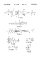
- FIG. 1 is a plan view of a first embodiment of a cryosurgical probe of the present invention.
- FIG. 2 is a longitudinal cross section of a first sub-assembly taken along line 1--1 of FIG. 1.
- FIG. 3 is a partial longitudinal cross section of a second sub-assembly of the probe of the present invention taken along line 1--1 of FIG. 1.
- FIG. 4 is a partial longitudinal cross section of a third sub-assembly taken along line 1--1 of FIG. 1.
- FIG. 5 is a longitudinal cross section of a fourth sub-assembly taken along line 1--1 of FIG. 1.
- FIG. 5a is a detail view of the discharge end of a cryogenic fluid supply tube having a converging nozzle.
- FIG. 5b is a detail view of the discharge end of a cryogenic fluid supply tube having a diverging nozzle.
- FIG. 6 is an alternative embodiment of the fourth sub-assembly of FIG. 5.
- FIG. 7 is a plan view of an embodiment of a handle body of a cryosurgical probe of the present invention.
- FIG. 8 is a partial longitudinal cross section of the assembled probe of FIG. 1 taken along line 1--1 of FIG. 1 illustrating the internal handle assembly.
- FIG. 8a is a cross sectional detail view of area A of FIG. 8.
- FIG. 9 is a longitudinal cross section of an embodiment of a thermal valve taken along line 9--9 of FIG. 1.
- FIG. 9a is a plan view of an alternative embodiment of a thermal valve body which may be used in the manufacture of a cryosurgical probe of the present invention.
- FIG. 10 is a longitudinal cross section of the thermal valve of FIG. 9 after activation thereof.
- FIG. 11 is a longitudinal cross section of the thermal valve of FIG. 10 with excess valve body removed.
- FIG. 12 is a longitudinal cross section of an alternative embodiment of a cryosurgical probe of this invention.
- FIG. 13 is a detail view of area A of FIG. 12.
- FIG. 14 is a detail view of area B of FIG. 12.
- FIG. 15 is a plan view of the end cap of FIG. 12.
- FIG. 16 is a cross section of the end cap of FIG. 15 taken along line 2--2 of FIG. 15.
- FIG. 17 is a detail view of area C of FIG. 12.
- FIG. 18 is a plan view of the probe of FIG. 12 with the handle body removed.
- FIG. 19 is an oblique view of an individual cryosurgical probe assembly of the present invention supported for final vacuum brazing.
- FIG. 20 is an oblique view of first and second subassemblies of the present invention supported for vacuum brazing.
- FIG. 21 is a cross sectional view of an apparatus for use in an alternative embodiment for introducing a valve ball into a valve body prior to activation.
- FIG. 22 is a cross sectional view of the apparatus of FIG. 21 following activation.
- FIG. 23 is a longitudinal cross section of a tubular probe shaft straightening tool for use in the manufacture of a cryosurgical probe of the present invention.
- FIG. 24 is a longitudinal cross section of the probe shaft straightening tool of FIG. 23 in place on a probe of the present invention.
- Cryosurgical probe assembly 1 shown in FIG. 1 and in an alternative embodiment 100 in FIG. 12, includes an elongated probe shaft portion 2, and a handle portion 3.
- Probe shaft portion 2 will typically have a length of from about 4 inches (about 10 cm) to about 12 inches (about 30 cm) depending on the intended end use, a preferred length being from about 6 inches (about 15 cm) to about 8 inches (about 20 cm).
- the probe shaft 10 of probe shaft portion 2 may typically have an outside diameter of at least about 1.5 mm, preferably at least about 2 mm and especially preferably at least about 3 mm. The upper limit will usually be about 10 mm.
- probe shaft portion 2 will usually have a straight configuration with its longitudinal axis coinciding with the longitudinal axis of the handle portion, the probe shaft portion, or at least the distal end thereof, which includes the freezing zone, may also be curved as will be described in further detail below. Still further, for particular applications, the probe shaft portion or at least the freezing tip portion that will come into contact with tissue to be destroyed may be of different configuration than the narrow tubular configuration shown in the drawings, such as well known in the art, for example, an enlarged flattened freezing surface for application to the liver, etc.
- Probe assembly 1 is constructed from sub-assemblies 4, 9, 15 and 25 illustrated in FIGS. 2-5, respectively, which are assembled in a substantially longitudinal and concentric arrangement as shown in FIG. 8 and alternatively in FIG. 12.
- Any suitable material for use in surgical situations and which is brazable may be used for the manufacture of probe 1, for example, stainless steel, ceramic, stainless steel alloys, aluminum alloys, nickel alloys, copper or copper alloys and the like; however, medical grade stainless steel is preferred.
- Austenitic stainless steel is especially preferred, particularly for the external parts of the instrument which will come into contact with the tissue of a patient to be treated.
- 304 stainless steel is an austenitic stainless steel and has a microstructure consisting predominantly of polycrystalline austenite.
- First sub-assembly 4 shown in FIG. 2, includes cryogenic fluid return tube 5 and connector tube 6.
- Cryogenic fluid return tube 5 preferably has an outside diameter which allows it to be inserted into the proximal end 7 of connector tube 6, as shown.
- a ring of brazing alloy filler (not shown in FIG. 2) is placed over cryogenic fluid return tube 5 and against proximal end 7 of connector tube 6.
- Proximal end 7 of connector tube 6 may be bored out to a slightly larger inside diameter so as to accommodate distal end 8 of cryogenic fluid return tube 5 and to permit cryogenic fluid return tube 5 and connector tube 6, when assembled, to present a substantially continuous inside diameter.
- Such a structure presents a substantially smooth conduit for return flow of cryogenic fluid.
- the length of connector tube 6 may be in the range of, for example, from 0.5 to 0.7 inches or more, while, cryogenic fluid return tube 5 preferably has a length of from 6 to 7 inches for the illustrated embodiment wherein the probe shaft portion is about 7 to 8 inches long. However, other dimensions may be selected depending on the desired final size of probe assembly 1. In the specific embodiments illustrated, the length of first sub-assembly 4 is between 6.5 and 7.5 inches. In an alternative embodiment, first sub-assembly 4 may be fabricated as a single element comprising connector tube 6 as a portion of enlarged outer diameter on the distal end 8 of cryogenic fluid return tube 5. Such an alternative would eliminate one brazing step.
- Second sub-assembly 9, shown in FIG. 3, is formed from first sub-assembly 4 and probe shaft 10 joined by brazing with a fill alloy brazing ring (not shown).
- First sub-assembly 4 may be provided with annular notch 11 in the outer surface of connector tube 6 to accommodate a fill alloy brazing ring (not shown) when first sub-assembly 4 is inserted into probe shaft 10.
- a fill alloy brazing ring (not shown) may be placed against proximal end 7 of connector tube 6 prior to insertion of first sub-assembly 4 into probe shaft 10.
- Probe shaft 10 preferably comprises a tubular body of about 8 inches in length having an open proximal end 12 and a closed distal end (probe tip) 13. Vent holes 14 are provided in probe shaft 10 at a location just distal of open proximal end 12 and their purpose will become evident later in this description.
- first sub-assembly 4 In assembly of second sub-assembly 9, a fill alloy brazing ring (not shown) is positioned on first sub-assembly 4 as described above. First sub-assembly 4 is then inserted into probe shaft 10, connector tube 6 first, so that a portion, e.g. about 0.6-0.7 inch, of the proximal end of cryogenic fluid return tube 5 extends from open proximal end 12 of probe shaft 10. The space between the outer surface of cryogenic fluid return tube 5 and the inner surface of probe shaft 10 forms coaxial lumen 51'. This distal end of first sub-assembly 4 is positioned from about 1 inch to about 2 inches from the closed probe tip 13 of probe shaft 10. This space forms the freezing chamber 10' (see FIG. 8).
- Second sub-assembly 9 is then brazed in a manner to be described to join probe shaft 10 and first sub-assembly 4.
- the size of freezing chamber 10' is easily changed during manufacture by altering the position to which first sub-assembly 4 is inserted into probe shaft 10 during assembly of second sub-assembly 9. Such alteration may also involve providing a shorter or longer first sub-assembly 4 or a shorter or longer probe shaft 10.
- freezing chamber 10' may be lengthened or shortened which will, in turn, change the shape and size of the iceball produced when the probe is in use.
- second sub-assembly 9 is combined with return tube extension 16, cup-shaped chamber body 17 and spacer 18 to form third sub-assembly 15 shown in FIG. 4.
- Spacer 18 may, for example, be formed of alumina or other ceramic material and is slidable over the proximal end of cryogenic fluid return tube 5 to be positioned within open proximal end 12 of probe shaft 10 between proximal end 12 and vent holes 14. Proximal end 12 may then be crimped over spacer 18 to hold it in place.
- spacer 18 has a snug fit within proximal end 12 of probe shaft 10 and a locking wire 18' is threaded through adjacent vent holes 14 to serve as means to ensure that spacer 18 remains at the proximal end 12 of probe shaft 10.
- FIG. 8a provides an enlarged cross section of the area of proximal end 12 of probe shaft 10 showing the relationship of spacer 18, probe shaft 10, return tube 5 and locking wire 18'.
- coaxial lumen 51' is closed off except for communication through vent holes 14.
- Coaxial lumen 51' thus forms a jacket around cryogenic fluid return tube 5 within probe shaft 10 and is evacuated during the final vacuum brazing and sealing of the fully assembled probe 1 to provide vacuum insulation along at least a substantial length of probe shaft 10.
- Return tube extension 16 may be about 6 inches long and has a diameter larger than that of cryogenic fluid return tube 5.
- the distal end 19 of return tube extension 16 is necked down to fit onto the proximal end of cryogenic fluid return tube 5 with a fill alloy brazing ring (not shown) positioned at the juncture thereof.
- Chamber body 17 is substantially cup shaped and connects to proximal end 20 of return tube extension 16 to provide an expansion space for cryogenic fluid passing out of probe portion 2 via cryogenic fluid return tube 5 and return tube extension 16.
- Distal end of chamber body 17 is substantially closed by wall 21 through which central bore 22 is drilled.
- Central bore 22 is of a diameter to accept proximal end 20 of return tube extension 16.
- Central bore 22 is preferably provided with a chamfer 23 at its distal end to facilitate insertion of return tube extension 16 and to accept a fill alloy brazing ring (not shown).
- annular shoulder 24 Surrounding central bore 22 and formed as part of chamber wall 21 is annular shoulder 24 which serves, in the final probe assembly 1, as a plug and support for proximal end 46 of handle body 38 (as shown in FIG. 8).
- Annular notch 24' in annular shoulder 24 may accept a fill alloy brazing ring (not shown) to join handle body 38 to chamber body 17.
- joining of handle body 38 to chamber body 17 may be effected by a fill alloy brazing ring (not shown) placed over handle body 38 at the juncture of proximal end 46 of handle body 38 and wall 21 of chamber body 17.
- Third sub-assembly 15 is constructed as described with fill alloy brazing rings (not shown) at the junction of cryogenic fluid return tube 5 and return tube extension 16 and at the junction of return tube extension 16 and chamber body 17, preferably in bore chamfer 23. Third sub-assembly 15 is then subjected to appropriate brazing conditions for the particular fill alloy and structural materials. Handle body 38 may also be assembled as part of third sub-assembly 15 at this time.
- Fourth sub-assembly 25 is shown in FIG. 5 and includes cryogenic fluid supply tube 26, supply tube extension 27 and end cap 28. All parts are preferably fabricated from the same material as the rest of probe assembly 1.
- Cryogenic fluid supply tube 26 may be, for example, from about 8 to about 9 inches long and with a diameter to fit concentrically within cryogenic fluid return tube 5 so as to provide a cryogenic fluid return lumen 50 (see FIG. 8) between the inner surface of cryogenic fluid return tube 5 and the outer surface of cryogenic fluid supply tube 26.
- Supply tube extension 27 may be about 6 inches long and is slightly larger in diameter than cryogenic fluid supply tube 26 and has its distal end 29 necked down to fit securely over the proximal end of cryogenic fluid supply tube 26.
- the diameter of supply tube extension 27 is such as to fit concentrically within return tube extension 16 so as to continue cryogenic fluid return lumen 50 therebetween.
- one or more vent holes are provided along the length of the supply tube, upstream of the connector tube and supply tube outlet (i.e. in the vacuum insulated region), to allow fluid communication between the inflowing liquid cryogen refrigerant and the outflowing or exhaust refrigerant in the cryogenic fluid return lumen.
- one relatively large diameter vent hole 70 in supply tube extension 27 and several, e.g. 3, relatively smaller diameter vent holes 72 in supply tube parts 26 and 27 are shown in FIG. 5.
- the larger supply tube vent hole 70 is preferably positioned along supply tube extension 27 so as to be located within the enlarged cryogenic fluid return chamber 48 upon insertion of fourth sub-assembly 25 into third sub-assembly 15.
- End cap 28 is a circular plate having a central bore 30 and a first radially offset bore 31.
- End cap central bore 30 is surrounded on the inner surface of end cap 28 by extension wall 32 which provides a place for end cap 28 to connect to the proximal end of supply tube extension 27.
- the inner end of end cap central bore 30 is preferably provided with a chamfer 33 to facilitate insertion of supply tube extension 27 and to accept a fill alloy brazing ring (not shown).
- End cap 28 has a diameter to fit over and close the open cup of chamber body 17.
- the periphery of end cap 28 is provided with a circumferential shoulder 34 which accepts circumferential chamfered edge 35 of chamber body 17.
- end cap 28 may have a second radially offset bore 36 to which is connected by brazing a short, closed end thermocouple well 37 extending inward.
- Thermocouple well 37 provides a space in which a thermocouple, or other temperature measuring device, may be placed to monitor the temperature of returning cryogenic fluid.
- Final probe assembly 1 is illustrated in FIG. 8 and is formed by assembling third sub-assembly 15, fourth sub-assembly 25, handle body 38, cryogenic fluid supply connector 39, and cryogenic fluid return connector 40.
- the embodiment illustrated in FIG. 1 includes optional thermally activated valve 41.
- An example of one embodiment of valve 41 is illustrated in different stages in FIGS. 9-11 and comprises valve body 42, ball 43 and activation wire 44.
- An alternative valve body form 242 is illustrated in FIG. 9a for use with the valve ball dispenser 156 of FIGS. 21 and 22 in a manner to be described later.
- the final evacuation may be affected directly through the narrow spaces left at the junctions between the assembled sub-components and the valve 41 may be omitted.
- Handle body 38 is illustrated in FIG. 7 and comprises a tubular body having a length of, for example, from about 6.5 to about 7.0 inches.
- the diameter of handle body 38 may be from about 0.5 to about 1.0 inch, preferably about 0.6 to 0.75 inch, and has an inside diameter corresponding substantially to the diameter of annular shoulder 24 on chamber wall 21 to fit thereon as shown in FIG. 8.
- Distal end 45 of handle body 38 is tapered to a size to fit over and engage probe shaft 10 at a location on the distal side of vents 14.
- valve hole 47 located in the wall of handle body 38, preferably slightly distally of proximal end 46, is valve hole 47 in which valve body 42 fits and is joined to handle body 38 preferably by vacuum brazing.
- handle body 38 is provided at this stage with valve body 42 already joined thereto. However, the joining of valve body 42 to handle body 38 at valve hole 47 may take place as part of the final assembly process.
- Probe 1 is assembled by inserting fourth sub-assembly 25 into third sub-assembly 15 through chamber body 17.
- Cryogenic fluid supply tube 26 extends through cryogenic fluid return tube 5 into probe shaft 10 and end cap 28 fits against circumferential chamfered edge 35 of chamber body 17 thereby closing chamber body 17 and forming a cryogenic fluid return chamber 48.
- This chamber 48 provides a final enlarged area for cryogenic fluid entering chamber 48 from cryogenic fluid return lumen 50 prior to exiting probe assembly 1.
- the space between cryogenic fluid supply tube 26 and cryogenic fluid return tube 5 and between supply and return tube extensions 27 and 16 forms a cryogenic fluid return lumen 50 which connects freezing chamber 10' and return chamber 48.
- cryogenic fluid supply and return connectors 39 and 40 are positioned in their respective bores 30 and 31 of end cap.
- Cryogenic fluid supply connector 39 fits into central bore 30 to be coextensive with supply tube extension 27 and cryogenic fluid supply tube 26.
- Cryogenic fluid return connector 40 fits into first radially offset end cap bore 31 and may extend part way into return chamber 48.
- screen 155 is placed over return tube extension 16 at a position so as to be distal of valve body 42 when handle body 38 is in place.
- Handle body 38 is applied over third sub-assembly 15 so that proximal end 46 of handle body 38 fits over annular shoulder 24 and engages chamber wall 21 while probe shaft 10 passes through distal end 45 of handle body 38.
- the assembly is such that proximal end 12 of probe shaft 10 is located within handle body 38.
- Handle space 51 is formed within handle body 38 as a lumen between the inner surface of handle body 38 and the outer surface of return tube extension 16 and communicates with coaxial lumen 51' of probe shaft 10 through vents 14.
- Screen 155 conforms to the shape of handle space 51 and may be a split disc of woven metallic screen material. Alternatively, screen 155 may be placed over return tube extension 16 during the assembly of third sub-assembly 15 prior to installation of chamber body 17. Screen 155 may be omitted but is preferably included as a means to confine getter tablets 54 within the proximal end of handle space 51 to prevent blockage of the connection between handle space 51 and coaxial lumen 51'.
- valve body 42 Prior to brazing the final assembly of FIG. 8, in the case where the thermally activated valve 41 is used, the assembly is oriented with valve body 42 uppermost. Since valve body 42 is a tubular structure and is mounted in valve hole 47, it provides access into and out of handle space 51 and, via vents 14, into and out of coaxial lumen 51'. Preferably, valve body 42 has an inner circumferential valve seat 52 at its lower end adjacent handle body 38 and below vent holes 53 in the wall of valve body 42 between the upper and lower ends thereof. Above vent holes 53 is a means to hold activation wire 44.
- Such a means may be two small holes in the wall of valve body 42 at positions opposite each other and above valve vent holes 53 through which activation wire 44 is threaded, or it may be an opposing pair of slits in the wall of valve body 42 terminating above valve vent holes 53 in which activation wire 44 is laid.
- Activation wire 44 spans the diameter of valve body 42 and provides a temporary support for ball 43 during the evacuation stage of brazing. Upon substantial completion of evacuation and reaching of brazing temperatures, activation wire 44 melts allowing ball 43 to drop down onto seat 52 below valve vent holes 53.
- a fill alloy brazing ring (not shown) is in place on seat 52 and seals ball 43 in place as shown in FIG. 10.
- activation wire 44 is a material which melts at or just below brazing temperatures. Any material having this characteristic may be used but a standard brazing wire having a thickness of about 0.005 inch and melting at a temperature of at least about 1000° F., preferably at least about 1300° F. such at least about 1500° F., is particularly preferred.
- Valve body 42 also provides a conduit by which a getter 54 is introduced into handle space 51.
- getter 54 is compressed in the form of a pill having a size to fit through valve body 41.
- Getter material appropriate to the materials being brazed is used, for example, ST 707 in pill form, available from SAES Pure Gas, Inc.
- getter 54 is introduced into handle space through valve hole 47 and valve body 242, shown in FIG. 9a, is placed in valve hole 47 with a fill alloy brazing ring (not shown) positioned on valve body 242 so as to be between the outer surface of handle body 38 and valve body perimeter flange 243 under valve body lip 244. In this manner, upon reaching brazing temperature in the furnace, valve body 242 will be brazed to handle body 38 so that only perimeter flange 243 is outside of handle body 38.
- valve ball dispenser 156 When alternative valve body 242 is used in the assembly of probes according to this invention, valve ball dispenser 156, shown in FIGS. 21 and 22, is used to introduce valve ball 43 at the correct moment into valve body 242 to seal to valve seat 252 within valve body 242.
- Valve ball dispenser 156 comprises a body having a curved valve ball channel 157 within the body wherein channel 157 connects with valve body 242 when dispenser 156 is positioned on handle body 38 as shown in FIGS. 21 and 22.
- Channel 157 also serves as a vent through which the probe interior is evacuated.
- Attachment band 158 retains dispenser 156 in place on handle body 38.
- Valve balls 43 are loaded into channel 157 and are held back away from valve body 242 by valve ball release 159.
- valve ball release 159 allows a valve ball 43 to roll forward into valve body 242 where ball 43 is brazed onto valve seat 252 by a fill alloy brazing ring (not shown) which is placed within valve body 242 prior to attachment of valve ball dispenser 156.
- probe handle body 38 and probe shaft 10 are evacuated and then sealed to retain the vacuum therein, thereby providing effective thermal insulation of handle portion 3 and probe portion 2.
- Valve ball release 159 may be in the nature of activation wire 44 which melts at the brazing temperature to allow passage of valve ball 43.
- valve ball release 159 may be a material which softens at brazing temperatures and bends to allow passage of valve ball 43 and then hardens upon reduction of the temperature to again prevent passage of valve balls 43.
- Such materials may include bi-metals selected to correspond to brazing temperatures or memory materials which can be set to have one shape or position at one temperature and another shape or position at another temperature.
- valve ball release 159 will take a position to block passage of valve balls 43 at temperatures below the brazing temperature and will take a position to allow passage of balls immediately before the brazing temperature is reached so that a valve ball 43 is released and is positioned in valve body 242 when the brazing temperature is reached.
- getter material may still be placed within the handle body portion, such as before assembling handle body 38 to chamber body 17, preferably in conjunction with screen 155.
- brazing alloys suitable for the conditions of the invention and the materials being brazed may be readily determined by the skilled in the art and any such brazing alloys may be used.
- Brazing alloy GB 8218 which has a composition of 82% gold and 18% nickel, and is available from Prines and Izant Co., has been successfully used.
- a further brazing alloy suitable for use herein is NICROBRAZ®, a nickel and chromium alloy, which is available from Wall Colmonoy Corporation.
- the brazing alloy may conveniently be provided as preformed rings of wire having diameters appropriate to their location of use, generally from 0.040 inch to 0.9 inch. The diameter of the wire from which the rings are made is from 0.010 to 0.025 inch, preferably 0.015-0.020 inch.
- the method of the invention will be described herein with reference to the particularly preferred material which is medical grade stainless steel.
- Other base materials or brazing alloys may require different temperatures, pressures, heating and cooling times, etc., which may be readily determined by the product or material specifications or by routine experimentation.
- the maximum brazing temperature will be no more than the softening or degradation temperature of the particular base material and will be at least the temperature at which the particular brazing material melts.
- the vacuum pressure must be sufficient to effectively, e.g., substantially fully, evacuate the probe assembly and to provide the required atmosphere for fluxless brazing.
- heating and cooling rates they may vary with the materials but should be such as to provide even and thorough heating or cooling of the assemblies being brazed. Cooling rates may also be affected by any annealing or tempering effect which is desired to be produced on the probes being manufactured according to the method.
- one of the unique advantages of vacuum brazing in connection with cryosurgical probes is the ability to control the flexibility of the probe shaft portion to achieve design configurations of the probe shaft in the final product which will be particularly well adapted for specific surgical procedures.
- the rigidity of the probe varies depending upon the materials, the structural design, the physical dimensions of the probe and the manufacturing process. The requirement for rigidity also varies depending upon the specific clinical applications and personal preference.
- the rigidity of the probe shaft is, therefore, a very subjective matter. Nevertheless, it would be beneficial to enhance the rigidity of the probe as close as possible to that of conventional probes, such as the TIG-welded probe, without altering the basic design and to maintain functional aspects of the probe design. Therefore, it is generally necessary to harden the probe shaft portion to fix the configuration into its desired shape and avoid undesired deformation during use. Moreover, in some cases, bending the probe shaft can adversely effect the vacuum insulation, for example, inducing cold spots under specific test conditions.
- 304 stainless steel material Due to its desirable mechanical properties at cryogenic temperatures, its availability in hypodermic tubing form, and its traditional use in the general medical field, 304 stainless steel material has been used to construct the cryoprobe body according to this invention.
- the material 304 stainless steel falls into the category of austenitic stainless steel and has a microstructure consisting predominantly of polycrystalline austenite. However, it cannot be strengthened by heat treatment such as quenching to form martensite or by precipitation hardening.
- strengthening of austenitic stainless steel is accomplished by cold working or solid solution treating. Cold working typically refers to work done on the steel below the thermal critical range and usually at ambient temperature. Common operations include cold rolling, cold pressing, cold drawing, cold extrusion, twisting and swaging, etc.
- 304 stainless steel By plastic deformation of the material taking it beyond its yield point, 304 stainless steel typically becomes harder and stronger. Cold working generally improves the yield and tensile strengths. Some of the less stable structural domains may actually undergo a phase transformation and create a martensite phase during cold working. Frequently, 304 stainless-steel material can also be hardened by the application of certain surface-hardening and modification techniques such as gas (or plasma) carburizing, gas carbonitriding, ion implantation and coating (vapor deposition) etc. These solution-treating techniques, however, will simultaneously alter the surface composition of the material. Ideally, the same 304 stainless-steel material should be used for the construction of the entire cryoprobe body or at least the external surface of the probe body which will be in contact with the patient. In order to reduce or eliminate surface composition alteration, the following optional treatments may be performed.
- the LN 2 return tube can be substituted with a heat-treatable steel such as martensitic stainless steel (e.g. 416) or martensitic-grade, precipitation-hardening stainless steel (e.g. 17.4 PH and 15-5 PH).
- a fully hardened return tube should substantially improve the rigidity of the probe shaft portion. To gain a fully hardened state, however, an additional heat-treatment process may last several hours or longer.
- the elongation of the tube, as a result of the martensite phase transformation, coupled with the uneven contraction caused by the cooling process may severely deform the probe shaft in a partially hardened or fully hardened condition which might make it more difficult to straighten than when in a relatively soft, annealed state (for the same reason, the use of martensitic stainless steel for the outer shell of the probe shaft will not generally be the best choice).
- the selection of brazing materials with relatively low melting temperatures, such as silver- or copper-based alloys, in combination with selection of base materials with relatively high recrystallization and annealing temperatures as well as high strength at a partially annealed or fully annealed state, such as Inconel 600 or 625 or Nitronic 50, may alleviate the problem to a certain extent.
- the application of materials of such kind together with a low brazing temperature in the neighborhood of 1300° F. and a shortened brazing cycle is one specific solution.
- the strength of the probe shaft can also be increased by increasing the outer diameter of the return tube (O.D. only).
- the outer diameter of the return tube can only be increased within its structural limitations. This approach, therefore, has limited potential for a 3.4 mm cryoprobe and is preferably used in combination with other strengthening techniques.
- the annealing effect can be further reduced.
- Studies conducted at multiple locations by or for the present inventors indicate that the use of low-temperature brazing alloys and thermal shielding are feasible from a technical point of view.
- the surface of the probe shaft can also be "cold-worked” by bombarding the outer surface with a stream of blasting media such as metal or glass beads, a process often referred to as shot peening.
- the degree of "cold-working” depends upon the peening intensity which, in turn, is a function of the diameter of the media, its density, as well as the velocity at which it strikes the surface. In practice, the striking velocity can be changed by varying the air pressure.
- the shot peening process only hardens a single (or few) layers of atoms on the external surface of the probe shaft.
- the swaging process i.e. cylindrical swaging has the advantage of hardening from the outer shell through the wall thickness and, therefore, potentially affords a much stronger probe shaft than the shot-peening process.
- the swaging process also has the advantage in that a more uniform diameter of the probe shaft can be more easily attained and avoid shaft diameter variations resulting from the tolerance of raw materials.
- the probe shaft should not be over swaged or under swaged. An under-swaged probe will not create the desired rigidity, while an over-swaged probe will compromise the structural integrity, heat-transfer efficiency and vacuum insulation.
- probe-shaft diameters possible after swaging e.g.
- inert glass shot-peening should be used in preference to steel shot-peening.
- size range of the glass beads should be monitored and controlled.
- the recommended sieve ranges of glass beads for peening are 20-30, 30-40, and 40-60.
- the glass shot-peening process serves primarily to refine the crystalline structure on the surface (rather than hardening).
- An additional desirable effect of glass shot peening is the clean appearance and decorative finish of the surface.
- Swaging is a chipless machining operation. Neither the swaging technique nor the shot peening will etch or remove basic materials or impart any undesirable residues.
- the chemical composition of the basic material remains unchanged after the proposed manufacturing process. According to the AISI (the American Iron and Steel Institute) standard, the basic materials of the final product can still be classified as 304 stainless steel.
- the swaging-peening process is simple to follow, and the dimensions can be precisely duplicated on an unlimited number of parts even when using operators with low levels of skill and experience.
- the sub-assemblies and the final assembly are brazed in a vacuum brazing oven at a temperature of at least about 1000° F., preferably at least 1300° F., such as about 1500° F. or higher and at low pressure, i.e. at least as low as 1 ⁇ 10 -3 Torr.
- a vacuum brazing oven at a temperature of at least about 1000° F., preferably at least 1300° F., such as about 1500° F. or higher and at low pressure, i.e. at least as low as 1 ⁇ 10 -3 Torr.
- brazing may be conducted at a temperature of about 1825 +/-0 ° F. and at a pressure of about 1 ⁇ 10 -5 Torr.
- the sub-assemblies are assembled and brazed in batches, the number of sub-assemblies in each batch being limited primarily by the size of the oven.
- the sub-assemblies are loaded into the oven and a vacuum is drawn on the oven.
- the temperature in the oven is increased to the brazing temperature, for example, at a rate of about 30°-50° F. per minute.
- the furnace is held at that temperature for about 10-30 minutes depending on the mass of material in the furnace.
- the furnace temperature is reduced, usually at about the same rate as the temperature raising rate, such as about 30°-50° F. down to a temperature below the melting or softening temperature to a temperature below about 1300° F.
- the vacuum is released and the furnace is force cooled with dry nitrogen to a temperature of, for example, about 100° F.
- the same procedure is followed with the exception that the temperature increase preferably occurs at a more gradual rate of, for example, about 10° F. per minute to ensure even heating of multiple layers.
- the sub-assemblies and final assembly are supported by fixtures preferably designed to hold a plurality of such assemblies and constructed of materials which can withstand the high temperatures and low pressures without adverse effect on the materials of the probes.
- a preferred material for these fixtures is graphite with a coating of boron nitrate.
- the fixtures hold the sub-assemblies and final assemblies in a horizontal position.
- the fixtures may be simple V-blocks 55, as shown in FIG. 19, of different heights to ensure that the probe assembly 1 is maintained in a level horizontal attitude or they may be specifically designed and fabricated with a configuration corresponding to the particular assemblies being vacuum brazed.
- the fixtures may be designed to be stackable, thereby providing multiple layers of assemblies in a stable arrangement.
- the various assemblies may be supported vertically for vacuum brazing in blocks 56 having multiple apertures 57 in one surface into which the sub-assemblies are inserted as shown in FIG. 20.
- valve body 242 and valve ball dispenser 156 are employed.
- the design of the fixtures will permit a maximum number of sub-assemblies and/or final assemblies to be loaded into the furnace for each vacuum brazing operation.
- a typical assembly of a probe according to the structure and method of the invention begins with first sub-assembly 4.
- Cryogenic fluid return tube 5 and connector tube 6 are assembled with a fill alloy brazing ring surrounding cryogenic fluid return tube 5 and pressed against proximal end 7 of connector tube 6.
- the fill alloy brazing ring may be about 0.083 inch in diameter which corresponds to the outside diameter of cryogenic fluid return tube 5.
- a plurality of first subassemblies 4 are loaded into a vacuum furnace which, between cycles, is maintained at a temperature of about 100° F. and a pressure of about 1 ⁇ 10 -3 Torr to remove condensation. Following loading, the furnace is closed, the pressure of about 1 ⁇ 10 -3 Torr is again established and the temperature is then increased to at least about 1500° F.
- the temperature of the furnace is reduced at a rate of 30°-50° F. per minute until about 1350° F. to about 1300° F. is reached at which time the vacuum is released and the furnace is force cooled with dry nitrogen to a temperature of about 100° F. and the first subassemblies 4 are removed and inspected.
- the furnace pressure may be reduced to about 1 ⁇ 10 -5 Torr for optimum brazing.
- Second sub-assemblies 9 are assembled by placing a fill alloy brazing ring either in annular notch 11 of first sub-assembly 4, or over return tube 5 against connector tube 6, and then placing first sub-assembly 4 inside probe shaft 10.
- the fill alloy brazing ring may be about 0.083 inch in diameter to provide a snug fit of first sub-assembly 4 in probe shaft 10.
- the method permits easy adjustment of the size of freezing chamber 10' by varying the lengths and/or the extent to which first sub-assembly 4 is inserted into probe shaft 10.
- the assembled second sub-assemblies 9 are vacuum brazed in one brazing cycle as described for first sub-assemblies and are then vacuum tested to ensure a good seal between connector tube 6 and probe shaft 10.
- Third sub-assemblies 15 are assembled from second subassemblies 9, return tube extension 16, chamber body 17 and spacer 18 with spacer 18 being placed within proximal end 12 of probe shaft 10 and proximal end 12 of probe shaft 10 being crimped to hold spacer 18 in place.
- locking wire 18' is threaded through adjacent vent holes 14 before spacer 18 is applied to thereby prevent passage of spacer 18 into probe shaft 10 beyond vent holes 14. In this manner, proximal end 12 of probe shaft 10 need not be crimped. It is particularly preferred that spacer 18 have a reasonably snug fit within probe shaft 10.
- spacer 18 may be installed when second sub-assemblies 9 are assembled and may also be vacuum brazed in place at that step.
- a fill alloy brazing ring which may be about 0.083 inch diameter is placed over cryogenic fluid return tube 5 and against distal end 19 of return tube extension 16 and a fill alloy brazing ring of about 0.156 inch diameter, which corresponds to the outside diameter of return tube extension 16, is placed around return tube extension 16 and within bore chamfer 23 on chamber body 17.
- Third sub-assemblies 15 are brazed as described and visually inspected then set aside for use in assembling final probe assemblies 1.
- Fourth sub-assemblies 25 are assembled from cryogenic fluid supply tube 26, supply tube extension 27 and end cap 28. If desired, thermocouple well 37 is also assembled to end cap 28. At this time, cryogenic fluid supply connector 39 and cryogenic fluid return connector 40 may be assembled to end cap 28 or they may be reserved until final assembly.
- Fill alloy brazing rings are positioned at appropriate locations, notably a ring of about 0.042 inch diameter, corresponding to the outside diameter of cryogenic fluid supply tube 26, is placed over cryogenic fluid supply tube 26 and against distal end 29 of supply tube extension 27 and a ring of about 0.083 inch diameter, corresponding to the outside diameter of supply tube extension 27, is placed over supply tube extension 27 to fit in chamfer 33 of end cap central bore 30. Fourth sub-assemblies are processed in one brazing cycle as described and the joints are visually inspected.
- fourth sub-assembly 25 is assembled to third sub-assembly 15 by insertion of cryogenic fluid supply tube 26 and supply tube extension 27 into cryogenic fluid return tube 5 and return tube extension 16.
- End cap 28 is placed against circumferential chamfered edge 35 of chamber body 17 so that edge 35 engages circumferential shoulder 34 of end cap 28.
- the mating edge 35 and shoulder 34 preferably cooperate to form an annular notch which accommodates a fill alloy brazing ring of about 0.875 inch diameter.
- a further fill alloy brazing ring of about 0.625 inch diameter is positioned in annular notch 24' of annular shoulder 24 and handle body 38 is placed over third sub-assembly 15.
- Annular shoulder 24 and the fill alloy brazing ring in notch 24' are received within proximal end 46 of handle body 38, as shown in FIG. 8, and a fill alloy brazing ring of about 0.134 inch diameter, corresponding to the diameter of probe shaft 10, is placed over probe shaft 10 against necked distal end 49 of handle body 38.
- proximal end 46 of handle body 38 is brazed to chamber wall 21 by means of a fill alloy brazing ring placed over handle body 38 and against chamber wall 21 rather than in notch 24'. If they were not included in the assembly of fourth sub-assembly 25, cryogenic fluid supply and return connectors 39 and 40 are installed at this time with fill alloy brazing rings of about 0.097 inch diameter positioned thereon against end cap 28.
- valve body 42 The final assemblies are positioned with valve body 42 uppermost and getter 54 is introduced into handle space 51 through valve body 42.
- Activation wire 44 and ball 43 if not preassembled, are installed on valve body 42 and the final assemblies are loaded into the furnace for brazing. If valve body 242 is employed, it is placed in valve hole 47 with an appropriate fill alloy brazing ring.
- Valve ball dispenser 156 is attached to probe 1 and the entire assembly is supported vertically, as shown in FIGS. 21 and 22, within the furnace.
- the furnace is loaded and evacuated to at least 1 ⁇ 10 -3 Torr, preferably about 1 ⁇ 10 -5 Torr. Evacuation at this stage serves a two-fold purpose. In addition to preparing the furnace for brazing, evacuation also draws a vacuum on handle space 51 through valve 41 and on coaxial lumen 51' which communicates with handle space 51 through vents 14. Vents 53 in valve body 42 communicate with handle space 51 through valve body 42. Following evacuation, the thermal schedule as previously described is applied. Preferably, however, the furnace temperature is increased to at least 1500° F., and preferably to about 1825 +30 / -0 ° F. at a rate of about 10° F. per minute.
- activation wire 44 melts allowing ball 43 to fall into valve body 42 onto seat 52 where the fill alloy brazing ring applied to seat 52 during assembly fuses ball 43 to seat 52 thereby closing valve 41.
- handle space 51 and coaxial lumen 51' are sealed and the vacuum therein is maintained following brazing thereby providing an evacuated insulating layer which extends for substantially the entire length of probe assembly 1 except for freezing chamber 10' at probe tip 13.
- the brazing temperature is held for about 10-30 minutes then decreased at a rate of about 30°-50° F. per minute to about 1300°-1350° F. at which point the furnace vacuum is released and the furnace is force cooled to 100° F. with dry nitrogen.
- Solvents appropriate to the materials used may be employed; however, a preferred pre-cleaning procedure is to clean the parts by vapor degreasing using a solvent such as Genusolv 54/33 in a Branson three-phase system where phase 1 is a boiling phase, phase 2 is a vapor phase, and phase 3 is an ultrasonic cleaning phase.
- FIGS. 12-17 An alternative construction embodiment of the probe of this invention is illustrated in FIGS. 12-17. Principally, this embodiment is a probe according to the present invention wherein chamber body 17 and cryogenic fluid return chamber 48 have been incorporated as part of return tube extension 16. The result is a sleeker, more streamlined probe 100 as shown in FIG. 12.
- first sub-assembly 104 is substantially identical to that of the first embodiment with connector tube 106, having notch 111 for receiving a brazing ring, being joined to cryogenic fluid return tube 105.
- second sub-assembly 109 probe shaft 110, including closed end 113 forming the probe tip, is placed over first sub-assembly 104 and vacuum brazing is carried out as previously described.
- a short portion of the proximal end of the return tube 105 will protrude from the open proximal end of the probe shaft 110.
- third sub-assembly 115 locking wire 118' is threaded through adjacent vent holes 114 and spacer 118 is placed over return tube 105 within proximal end of probe shaft 110.
- Return tube extension 116 is joined to cryogenic fluid return tube 105 as in the first embodiment.
- the structure of return tube extension 116 is different.
- Return tube extension 116 is formed with a larger diameter along its entire length, distal end 119 being tapered down to join cryogenic fluid return tube 105. The effect is to increase the volume of that portion of cryogenic fluid return lumen 150 between return tube extension 116 and supply tube extension 127 as seen in FIGS. 12 and 14. This portion of lumen 150 then also serves as the cryogenic fluid return chamber 48 of the first embodiment.
- Fourth sub-assembly 125 is also substantially identical to fourth sub-assembly 25 of the first embodiment and comprises cryogenic fluid supply tube 126, supply tube extension 127 and end cap 128 which are joined by vacuum brazing.
- Supply tube vent holes 170 and 172 are located along the length of the supply tube 126 and supply tube extension 127.
- Supply tube 126 may also be formed with a converging nozzle 60 or a diverging nozzle 61 as shown in FIGS. 5a and 5b.
- the design of end cap 128 is modified to accommodate the alternative construction of this embodiment as shown in FIGS. 15 and 16 and incorporates features of chamber body 17.
- end cap 128 includes end cap central bore 130 and first radial offset bore 131, supply tube extension 127 being joined to end cap central bore 130 while first offset bore 131 provides access to lumen 150 for cryogenic fluid return connector 140.
- Cryogenic fluid supply connector 139 joins to end cap central bore 130.
- Circumferential shoulder 134 provides a mating surface for proximal end 146 of handle body 138.
- Annular shoulder 124 corresponds to annular shoulder 24 of the first embodiment and fits in proximal end 146 of handle body 138 in a similar plug like manner.
- Within annular shoulder 124 is a central end cap recess 122 which corresponds to bore 22 of chamber body 17 and in which proximal end 120 of return tube extension 116 fits upon final assembly.
- End cap recess 122 is bounded by wall 122' and encompasses end cap central bore 130 and first radial offset end cap bore 131.
- FIG. 18 shows a partial final assembly with end cap 128 in place on proximal end 120 of return tube extension 116.
- Vents 114 in probe shaft 110 correspond to vents 14 in the first embodiment and serve to provide communication between handle space 151 and coaxial lumen 151' (see FIG. 13) for evacuation during the final vacuum brazing step of this embodiment.
- vents 114 will be proximal to necked end 149 of handle body 138 and will, therefor, be within handle space 151.
- FIG. 17 shows a detail cross section of the assembly with handle body 138 in place and valve ball 143 sealed to valve seat 152 in valve body 142.
- getter pills 154 are inserted through valve 141prior to final brazing.
- mesh screen 155 is positioned distally of valve 141 between return tube extension 116 and handle body 138. The subassemblies and the final assembly may be brazed in the same manner as described for the first embodiment.
- return tube extension 116 may be assembled to cryogenic fluid return tube 105 as part of first sub-assembly 104 thus eliminating the third sub-assembly step.
- spacer 118 and a fill alloy brazing ring are pre-positioned on return tube 105 before return tube extension 116 is added and this assembly is inserted into probe shaft 110 a sufficient distance for connector tube 106 to pass vent holes 114 at which point locking wire 118' is installed and the sub-assembly is completed.
- the probe constructions and method of this invention eliminate the need for separate and complicated evacuation procedures which have been previously necessary to achieve thermal insulation of probe handles.
- the overall construction produces a probe with reduced flow resistance over prior welded or press-fit constructions.
- vacuum brazing is a fluxless process and substitutes the vacuum for mineral fluxes used in other methods, more uniform joints are obtained and the vacuum insulation is less susceptible to degradation. Because fluxes are not used, the cryoprobes of the invention experience a minimum of base-metal outgassing which, in prior constructions, degrades the joints. Accordingly, the present invention results in longer shelf life periods for the probes produced.
- the method of this invention is suitable for high volume production operations and results in high quality probes with high uniformity and consistency. Accordingly, the method of this invention is more economical in terms of labor and materials and produces greater numbers of probes at lower cost thereby justifying disposability of the probes after use and eliminating defects that appear as the result of reuse.
- the vacuum brazing method presented herein contributes to a particularly desirable feature of the probes of the invention.
- the probes may be produced with the probe portion perfectly straight, occasions arise where it is convenient to provide a curved probe shaft.
- the slow cooling of the furnace from brazing temperature to about 1300° F. or below provides an annealing process which results in increased flexibility of the probe shaft portion allowing the shaft to be bent to a particular shape yet retain sufficient rigidity to hold that shape until re-bent.
- the probe portion may be bent to a particular shape during assembly then heat treated to fix the bend angle.
- Such treatment is a function of the vacuum brazing process and is accomplished by adjusting the cool down step to provide annealing or tempering of the probe material.
- any of the methods described previously may be applied to the probe shaft or other elements of the probe.
- the combined swaging and shot-peening process described above may be advantageously applied to the probe shaft, particularly those probe shafts having diameters below about 5 millimeters, such as about 3 or 4 millimeters.
- Probe shaft tool 160 comprises an elongated block of rigid material, preferably stainless steel, which has a centrally disposed bore 162 extending longitudinally through block 161. Longitudinal bore 162 is divided into probe cavity 163, which has a diameter sufficient to receive handle portions 3 and 103 of probes 1 and 100, and a shaft channel 164, which has a diameter sufficient to receive probe portions 2 and 102 of probes 1 and 100.
- the diameter of shaft channel 164 is just large enough to permit a straight probe portion to pass through and will thereby exert a straightening effect on a curved or bent probe which is inserted therein.
- probe shaft tool 160 is preferably of a length to permit substantially the full length of probe portions 2 and 102 to be received in shaft channel 164. Where it is desired to provide a particular curvature to probe portions 2 and 102, tool 160 may be provided with a curved shaft channel 164 so that probe portions 2 and 102 will bend to that curvature when they are inserted.
- tool 160 is placed over probes 1 or 100 so that handle portion 3 or 103 is received within probe cavity 163 and probe portions 2 or 102 extend through shaft channel 164 as shown in FIG. 24.
- Liquid nitrogen, or other cryogenic fluid is provided to probe 1 or 100 through cryogenic fluid hose 165 and is circulated through probe 1 or 100 for about 3-5 minutes. Flow of cryogenic fluid is then stopped and the probe is allowed to warm until frost melts at which time tool 160 is removed. The cooling and warming of the probe while tool 160 is in place facilitates retention of the set given to the probe shaft by tool 160.
- the design of the probes and their method of manufacture also contribute to safety and versatility. Since there are fewer joints and the annealing or tempering effect of brazing renders them stress free, the probes withstand thermal shock with higher reliability and consistency. In addition, no welded joints are exposed for possible contact with the patient. Versatility is improved due to the method of construction which permits ready variation in the length of the freezing chamber which allows the actual freezing area of the tip to be easily changed during construction to provide probes which will produce different size ice balls. In addition, the compact design permits multiple probes to be positioned in a limited surgical area.
- vacuum brazed cryoprobes have many advantages over conventional cryoprobes of the same or similar design but wherein the various parts are connected by other welding or brazing techniques.
- supply tube vented cryoprobes and most notably those with small diameter probe shafts, e.g. 3 millimeter cryoprobes, of the type described in the aforementioned U.S. Pat. No. 5,254,116 and copending application Ser. No. 08/137,353
- the external probe tip temperature could be lowered to that achieved with the Tig-welded cryoprobes (about -140° C. or lower) and in substantially the same time periods, e.g. within about 20 minutes, preferably within about 15 minutes, by providing a nozzle at the supply tube outlet (discharge end). Further optimization is achieved by the configuration of the supply tube vent hole design (number of holes, location of holes, diameter of holes, etc.).
- the nozzle may be either converging, i.e. (D-Do)/Do ⁇ 0, where D is the nominal inner diameter of the nozzle and Do is the nominal inner diameter of the regular supply tube (e.g. 0.035 inch in a 3 millimeter cryoprobe), or diverging, i.e. (D-Do)/Do>0.
- a supply tube with a converging nozzle 60 at its discharge end is shown in FIG. 5a and a supply tube with a diverging nozzle 61 at its discharge end is shown in FIG. 5b.
- the nozzles may be formed by any conventional technique, such as with a tapered tool of appropriate dimensions.
- a nominal 3 mm e.g. 3.4 mm
- vent hole design which includes one large diameter (about 0.027") vent hole (70) in enlarged chamber 48 and four smaller (about 0.007" diameter) vent holes (72).
- the four smaller vent holes 72 may be equi-spaced along supply tube 26 and extension 27, starting, for example, at about 0.5 inch to 1.0 inch from the discharge end of the supply tube and extending to about 8 to 10 inches from the discharge end, such that one small hole 72 is located in extension 27 and three are located in supply tube 26.
- the three vent holes 72 located in supply tube 26 may be located within about 0.5 inch to 0.6 inch, 0.75 to 0.9 inch, and 1.0 to 1.2 inch, respectively, from the discharge end, such that the forwardmost hole is located within the freeze zone (i.e. distally of the vacuum insulation), the intermediate hole is located at or near the inlet to the cryogenic fluid return lumen 50, and the rearmost hole is located within the cryogenic fluid return lumen 50.
- the fourth vent hole 72 is located in supply tube connector 27 forwardly of (i.e. downstream) chamber body 17 and enlarged return chamber 48.
Abstract
Description
                                  TABLE 1
__________________________________________________________________________
              Ice ball Size (after 15 min.
        Cool-Down
              Freezing in Water at 17° C.)
                                 Minimum
        Time (Sec.)
              (n = 3)            Temperature
        (n = 3)
              Dia. (mm)
                    Length (mm)
                           Weight (g)
                                 in Gel (°C.)
__________________________________________________________________________
Standard Probe
        62.2 ± 4.7
              30.7 ± 1.5
                    48.8 ± 1.3
                           20.8 ± 2.0
                                 -152 ± 29
(0.132"-0.134")                  (n = 4)
Swaged-Shot-
        61.7 ± 9.7
              29.4 ± 2.0
                    48.9 ± 1.8
                           19.4 ± 3.1
                                 -145 ± 28
Peened Probe                     (n = 5)
(0.130")
__________________________________________________________________________
                                  TABLE 2
__________________________________________________________________________
                                    Bending
                                           Buckling
                                                Tensile
                                                      Bursting
        Bending Moment (in. lbs.) (n = 3)
                                    Load   Load Yield Pressure
        10°
             20°
                  30°
                        40°
                              Ulti. (Lbs) (n = 1)
                                           (Lbs.)
                                                Load (Lbs.)
                                                      (psi) (n
__________________________________________________________________________
                                                      = 3)
TIG-Welded
        3.5 ± 0.2
             6.8 ± 0.1
                  10.5 ± 0.1
                        15.1 ± 0.1
                              26.6 ± 0.4
                                    28.1   83 ± 3.6
                                                763 ± 78.9
                                                      9700 ± 1400 (C)
(0.134")
Swaged-Shot-
        4.2 ± 0.0
             7.0 ± 0.1
                   9.1 ± 0.1
                        10.0 ± 0.1
                              10.9 ± 0.1
                                    14.2   80 ± 9.8
                                                287 ± 14.8
                                                      8100 ± 0 (H)
Peened Probe
(0.130")
Standard Probe
        3.5 ± 0.1
             4.9 ± 0.1
                  5.4 ± 0.0
                        6.3 ± 0.1
                              6.8 ± 0.1
                                    7.9    64 ± 6.5
                                                200 ± 8.2
                                                      7233 ± 850 (C)
(0.132"-0.134")
__________________________________________________________________________
 Notes:
 "C" and "H" denote respectively bursting at teflon connectors and handle
 of the probe
Claims (26)
Priority Applications (1)
| Application Number | Priority Date | Filing Date | Title |
|---|---|---|---|
| US08/372,121 US5573532A (en) | 1995-01-13 | 1995-01-13 | Cryogenic surgical instrument and method of manufacturing the same |
Applications Claiming Priority (1)
| Application Number | Priority Date | Filing Date | Title |
|---|---|---|---|
| US08/372,121 US5573532A (en) | 1995-01-13 | 1995-01-13 | Cryogenic surgical instrument and method of manufacturing the same |
Publications (1)
| Publication Number | Publication Date |
|---|---|
| US5573532A true US5573532A (en) | 1996-11-12 |
Family
ID=23466793
Family Applications (1)
| Application Number | Title | Priority Date | Filing Date |
|---|---|---|---|
| US08/372,121 Expired - Lifetime US5573532A (en) | 1995-01-13 | 1995-01-13 | Cryogenic surgical instrument and method of manufacturing the same |
Country Status (1)
| Country | Link |
|---|---|
| US (1) | US5573532A (en) |
Cited By (151)
| Publication number | Priority date | Publication date | Assignee | Title |
|---|---|---|---|---|
| US5716353A (en) * | 1996-05-03 | 1998-02-10 | Urds, Corp. | Cryosurgical instrument |
| US5846235A (en) * | 1997-04-14 | 1998-12-08 | Johns Hopkins University | Endoscopic cryospray device |
| WO1999037226A1 (en) * | 1998-01-23 | 1999-07-29 | Del Mar Medical Technologies, Inc. | Selective organ hypothermia method and apparatus |
| US6042559A (en) * | 1998-02-24 | 2000-03-28 | Innercool Therapies, Inc. | Insulated catheter for selective organ perfusion |
| US6096068A (en) * | 1998-01-23 | 2000-08-01 | Innercool Therapies, Inc. | Selective organ cooling catheter and method of using the same |
| US6149677A (en) * | 1998-03-31 | 2000-11-21 | Innercool Therapies, Inc. | Circulating fluid hypothermia method |
| US6161543A (en) * | 1993-02-22 | 2000-12-19 | Epicor, Inc. | Methods of epicardial ablation for creating a lesion around the pulmonary veins |
| US6182666B1 (en) | 1996-12-26 | 2001-02-06 | Cryogen, Inc. | Cryosurgical probe and method for uterine ablation |
| US6224624B1 (en) | 1998-03-24 | 2001-05-01 | Innercool Therapies, Inc. | Selective organ cooling apparatus and method |
| US6238428B1 (en) | 1998-01-23 | 2001-05-29 | Innercool Therapies, Inc. | Selective organ cooling apparatus and method employing turbulence-inducing element with curved terminations |
| US6241722B1 (en) | 1998-06-17 | 2001-06-05 | Cryogen, Inc. | Cryogenic device, system and method of using same |
| US6245095B1 (en) | 1998-03-24 | 2001-06-12 | Innercool Therapies, Inc. | Method and apparatus for location and temperature specific drug action such as thrombolysis |
| US6251129B1 (en) | 1998-03-24 | 2001-06-26 | Innercool Therapies, Inc. | Method for low temperature thrombolysis and low temperature thrombolytic agent with selective organ temperature control |
| US6251130B1 (en) | 1998-03-24 | 2001-06-26 | Innercool Therapies, Inc. | Device for applications of selective organ cooling |
| US6254626B1 (en) | 1998-03-24 | 2001-07-03 | Innercool Therapies, Inc. | Articulation device for selective organ cooling apparatus |
| US6261312B1 (en) | 1998-06-23 | 2001-07-17 | Innercool Therapies, Inc. | Inflatable catheter for selective organ heating and cooling and method of using the same |
| US6270494B1 (en) | 1996-12-26 | 2001-08-07 | Cryogen, Inc. | Stretchable cryoprobe sheath |
| US6270493B1 (en) | 1999-07-19 | 2001-08-07 | Cryocath Technologies, Inc. | Cryoablation structure |
| US6312452B1 (en) | 1998-01-23 | 2001-11-06 | Innercool Therapies, Inc. | Selective organ cooling catheter with guidewire apparatus and temperature-monitoring device |
| US6325818B1 (en) | 1999-10-07 | 2001-12-04 | Innercool Therapies, Inc. | Inflatable cooling apparatus for selective organ hypothermia |
| US6379378B1 (en) | 2000-03-03 | 2002-04-30 | Innercool Therapies, Inc. | Lumen design for catheter |
| US6464716B1 (en) | 1998-01-23 | 2002-10-15 | Innercool Therapies, Inc. | Selective organ cooling apparatus and method |
| US6471717B1 (en) | 1998-03-24 | 2002-10-29 | Innercool Therapies, Inc. | Selective organ cooling apparatus and method |
| US6491716B2 (en) | 1998-03-24 | 2002-12-10 | Innercool Therapies, Inc. | Method and device for applications of selective organ cooling |
| US6491039B1 (en) | 1998-01-23 | 2002-12-10 | Innercool Therapies, Inc. | Medical procedure |
| US6530234B1 (en) | 1995-10-12 | 2003-03-11 | Cryogen, Inc. | Precooling system for Joule-Thomson probe |
| US6551349B2 (en) | 1998-03-24 | 2003-04-22 | Innercool Therapies, Inc. | Selective organ cooling apparatus |
| US6558412B2 (en) | 1998-01-23 | 2003-05-06 | Innercool Therapies, Inc. | Selective organ hypothermia method and apparatus |
| US6576002B2 (en) | 1998-03-24 | 2003-06-10 | Innercool Therapies, Inc. | Isolated selective organ cooling method and apparatus |
| US6585752B2 (en) | 1998-06-23 | 2003-07-01 | Innercool Therapies, Inc. | Fever regulation method and apparatus |
| US6589234B2 (en) | 2001-09-27 | 2003-07-08 | Cryocath Technologies Inc. | Cryogenic medical device with high pressure resistance tip |
| US6595967B2 (en) | 2001-02-01 | 2003-07-22 | Innercool Therapies, Inc. | Collapsible guidewire lumen |
| US6599312B2 (en) | 1998-03-24 | 2003-07-29 | Innercool Therapies, Inc. | Isolated selective organ cooling apparatus |
| US6602276B2 (en) | 1998-03-31 | 2003-08-05 | Innercool Therapies, Inc. | Method and device for performing cooling- or cryo-therapies for, e.g., angioplasty with reduced restenosis or pulmonary vein cell necrosis to inhibit atrial fibrillation |
| US6648906B2 (en) | 2000-04-06 | 2003-11-18 | Innercool Therapies, Inc. | Method and apparatus for regulating patient temperature by irrigating the bladder with a fluid |
| US6660028B2 (en) | 2000-06-02 | 2003-12-09 | Innercool Therapies, Inc. | Method for determining the effective thermal mass of a body or organ using a cooling catheter |
| US6685732B2 (en) | 1998-03-31 | 2004-02-03 | Innercool Therapies, Inc. | Method and device for performing cooling- or cryo-therapies for, e.g., angioplasty with reduced restenosis or pulmonary vein cell necrosis to inhibit atrial fibrillation employing microporous balloon |
| US6719779B2 (en) | 2000-11-07 | 2004-04-13 | Innercool Therapies, Inc. | Circulation set for temperature-controlled catheter and method of using the same |
| US6719723B2 (en) | 2000-12-06 | 2004-04-13 | Innercool Therapies, Inc. | Multipurpose catheter assembly |
| US20040078033A1 (en) * | 2002-08-26 | 2004-04-22 | Alexander Levin | Cryosurgical instrument and its accessory system |
| US6726708B2 (en) | 2000-06-14 | 2004-04-27 | Innercool Therapies, Inc. | Therapeutic heating and cooling via temperature management of a colon-inserted balloon |
| US6830581B2 (en) | 1999-02-09 | 2004-12-14 | Innercool Therspies, Inc. | Method and device for patient temperature control employing optimized rewarming |
| US6843800B1 (en) | 1998-01-23 | 2005-01-18 | Innercool Therapies, Inc. | Patient temperature regulation method and apparatus |
| US20050198972A1 (en) * | 2004-03-10 | 2005-09-15 | Lentz David J. | Pressure-temperature control for a cryoablation catheter system |
| US20050261671A1 (en) * | 2001-05-31 | 2005-11-24 | Baust John G | Cryogenic system |
| US20050288658A1 (en) * | 2002-10-04 | 2005-12-29 | Sanarus Medical, Inc. | Method and system for cryoablating tumors |
| US20060167398A1 (en) * | 2005-01-25 | 2006-07-27 | Thermopeutix Inc. | System and methods for selective thermal treatment |
| US20080110182A1 (en) * | 2006-11-10 | 2008-05-15 | Vancelette David W | Coaxial Cryogenic Refrigeration Coupler |
| US20080119838A1 (en) * | 2006-11-17 | 2008-05-22 | Vancelette David W | Disposable Sheath with Replaceable Console Probes for Cryosurgery |
| US20080147055A1 (en) * | 2006-12-19 | 2008-06-19 | Endocare, Inc. | Cryosurgical Probe With Vacuum Insulation Tube Assembly |
| US20090126910A1 (en) * | 2007-11-19 | 2009-05-21 | International Businiess Machines Corporation | Apparatus and method for facilitating servicing of a liquid-cooled electronics rack |
| WO2009067497A1 (en) * | 2007-11-21 | 2009-05-28 | Endocare, Inc. | Flexible multi-tubular cryoprobe |
| US7678108B2 (en) | 2004-06-02 | 2010-03-16 | Medtronic, Inc. | Loop ablation apparatus and method |
| US7678111B2 (en) | 1997-07-18 | 2010-03-16 | Medtronic, Inc. | Device and method for ablating tissue |
| US7699805B2 (en) | 1998-07-07 | 2010-04-20 | Medtronic, Inc. | Helical coil apparatus for ablation of tissue |
| US20100100088A1 (en) * | 2003-06-25 | 2010-04-22 | Endocare, Inc. | Cryosurgical probe with adjustable sliding apparatus |
| US7706882B2 (en) | 2000-01-19 | 2010-04-27 | Medtronic, Inc. | Methods of using high intensity focused ultrasound to form an ablated tissue area |
| US7706894B2 (en) | 2000-10-10 | 2010-04-27 | Medtronic, Inc. | Heart wall ablation/mapping catheter and method |
| US20100137853A1 (en) * | 2007-05-31 | 2010-06-03 | Aumaitre Olivier | Cryogenic device for surgical use |
| US7740623B2 (en) | 2001-01-13 | 2010-06-22 | Medtronic, Inc. | Devices and methods for interstitial injection of biologic agents into tissue |
| US7744562B2 (en) | 2003-01-14 | 2010-06-29 | Medtronics, Inc. | Devices and methods for interstitial injection of biologic agents into tissue |
| US7758580B2 (en) | 2004-06-02 | 2010-07-20 | Medtronic, Inc. | Compound bipolar ablation device and method |
| US7758576B2 (en) | 2004-06-02 | 2010-07-20 | Medtronic, Inc. | Clamping ablation tool and method |
| US20100180607A1 (en) * | 2009-01-21 | 2010-07-22 | Endocare, Inc. | High pressure cryogenic fluid generator |
| US7794460B2 (en) | 1995-02-22 | 2010-09-14 | Medtronic, Inc. | Method of ablating tissue |
| US20100241114A1 (en) * | 2009-03-20 | 2010-09-23 | Salvatore Privitera | Cryogenic probe |
| US20100256621A1 (en) * | 2009-04-06 | 2010-10-07 | Cryomedix Llc | Single phase liquid refrigerant cryoablation system with multitubular distal section and related method |
| US7818039B2 (en) | 2000-04-27 | 2010-10-19 | Medtronic, Inc. | Suction stabilized epicardial ablation devices |
| US7824399B2 (en) | 2001-04-26 | 2010-11-02 | Medtronic, Inc. | Ablation system and method of use |
| US20100280507A1 (en) * | 2009-04-30 | 2010-11-04 | Cryomedix Llc | Cryoablation system having docking station for charging cryogen containers and related method |
| US7857781B2 (en) | 1998-04-21 | 2010-12-28 | Zoll Circulation, Inc. | Indwelling heat exchange catheter and method of using same |
| US20110009854A1 (en) * | 2007-11-21 | 2011-01-13 | Endocare, Inc. | Expandable multi-tubular cryoprobe |
| US7871409B2 (en) | 2003-04-29 | 2011-01-18 | Medtronic, Inc. | Endocardial dispersive electrode for use with a monopolar RF ablation pen |
| US7875028B2 (en) | 2004-06-02 | 2011-01-25 | Medtronic, Inc. | Ablation device with jaws |
| US7938822B1 (en) | 2010-05-12 | 2011-05-10 | Icecure Medical Ltd. | Heating and cooling of cryosurgical instrument using a single cryogen |
| US7951183B2 (en) | 1998-01-23 | 2011-05-31 | Innercool Therapies, Inc. | Medical procedure |
| US7959626B2 (en) | 2001-04-26 | 2011-06-14 | Medtronic, Inc. | Transmural ablation systems and methods |
| US7963963B2 (en) | 2002-10-30 | 2011-06-21 | Medtronic, Inc. | Electrosurgical hemostat |
| US7967814B2 (en) | 2009-02-05 | 2011-06-28 | Icecure Medical Ltd. | Cryoprobe with vibrating mechanism |
| US7967816B2 (en) | 2002-01-25 | 2011-06-28 | Medtronic, Inc. | Fluid-assisted electrosurgical instrument with shapeable electrode |
| US7967815B1 (en) | 2010-03-25 | 2011-06-28 | Icecure Medical Ltd. | Cryosurgical instrument with enhanced heat transfer |
| US7975703B2 (en) | 2002-05-16 | 2011-07-12 | Medtronic, Inc. | Device and method for needle-less interstitial injection of fluid for ablation of cardiac tissue |
| US8043283B2 (en) | 1998-03-31 | 2011-10-25 | Innercool Therapies, Inc. | Method and device for performing cooling- or cryo-therapies for, e.g., angioplasty with reduced restenosis or pulmonary vein cell necrosis to inhibit atrial fibrillation |
| US8043351B2 (en) | 1998-03-31 | 2011-10-25 | Innercool Therapies, Inc. | Method and device for performing cooling- or cryo-therapies for, e.g., angioplasty with reduced restenosis or pulmonary vein cell necrosis to inhibit atrial fibrillation employing tissue protection |
| US20110282341A1 (en) * | 2010-05-11 | 2011-11-17 | Electromedical Associates, Llc | Brazed electrosurgical device |
| US8080005B1 (en) | 2010-06-10 | 2011-12-20 | Icecure Medical Ltd. | Closed loop cryosurgical pressure and flow regulated system |
| US8083733B2 (en) | 2008-04-16 | 2011-12-27 | Icecure Medical Ltd. | Cryosurgical instrument with enhanced heat exchange |
| EP2420195A1 (en) * | 2010-08-18 | 2012-02-22 | Erbe Elektromedizin GmbH | Device for the fluid-conveying connection of at least one application probe with a supply tubing set, and handle for a surgical instrument |
| US8162933B2 (en) | 2000-04-27 | 2012-04-24 | Medtronic, Inc. | Vibration sensitive ablation device and method |
| US8162812B2 (en) | 2009-03-12 | 2012-04-24 | Icecure Medical Ltd. | Combined cryotherapy and brachytherapy device and method |
| US8221402B2 (en) | 2000-01-19 | 2012-07-17 | Medtronic, Inc. | Method for guiding a medical device |
| US8221415B2 (en) | 2001-04-26 | 2012-07-17 | Medtronic, Inc. | Method and apparatus for tissue ablation |
| US8333764B2 (en) | 2004-05-12 | 2012-12-18 | Medtronic, Inc. | Device and method for determining tissue thickness and creating cardiac ablation lesions |
| US8409219B2 (en) | 2004-06-18 | 2013-04-02 | Medtronic, Inc. | Method and system for placement of electrical lead inside heart |
| US8414573B2 (en) | 2002-05-16 | 2013-04-09 | Medtronic, Inc. | Device and method for ablation of cardiac tissue |
| US20130152651A1 (en) * | 2006-10-30 | 2013-06-20 | Codman & Shurtleff, Inc. | Stylet having a roughened outer surface |
| US8475441B2 (en) | 2008-12-23 | 2013-07-02 | Cryomedix, Llc | Isotherm-based tissue ablation control system |
| US8512337B2 (en) | 2001-04-26 | 2013-08-20 | Medtronic, Inc. | Method and system for treatment of atrial tachyarrhythmias |
| EP2630982A1 (en) * | 2012-02-22 | 2013-08-28 | ERBE Elektromedizin GmbH | Surgical cryoprobe instrument and vented connector for same |
| US8568409B2 (en) | 2000-03-06 | 2013-10-29 | Medtronic Advanced Energy Llc | Fluid-assisted medical devices, systems and methods |
| US8632533B2 (en) | 2009-02-23 | 2014-01-21 | Medtronic Advanced Energy Llc | Fluid-assisted electrosurgical device |
| US8663245B2 (en) | 2004-06-18 | 2014-03-04 | Medtronic, Inc. | Device for occlusion of a left atrial appendage |
| US8801707B2 (en) | 2004-05-14 | 2014-08-12 | Medtronic, Inc. | Method and devices for treating atrial fibrillation by mass ablation |
| US8821488B2 (en) | 2008-05-13 | 2014-09-02 | Medtronic, Inc. | Tissue lesion evaluation |
| US8870864B2 (en) | 2011-10-28 | 2014-10-28 | Medtronic Advanced Energy Llc | Single instrument electrosurgery apparatus and its method of use |
| US8882756B2 (en) | 2007-12-28 | 2014-11-11 | Medtronic Advanced Energy Llc | Fluid-assisted electrosurgical devices, methods and systems |
| US8920417B2 (en) | 2010-06-30 | 2014-12-30 | Medtronic Advanced Energy Llc | Electrosurgical devices and methods of use thereof |
| US8926635B2 (en) | 2004-06-18 | 2015-01-06 | Medtronic, Inc. | Methods and devices for occlusion of an atrial appendage |
| US9023040B2 (en) | 2010-10-26 | 2015-05-05 | Medtronic Advanced Energy Llc | Electrosurgical cutting devices |
| US9113896B2 (en) | 1998-07-07 | 2015-08-25 | Medtronic, Inc. | Method and apparatus for creating a bi-polar virtual electrode used for the ablation of tissue |
| US9138289B2 (en) | 2010-06-28 | 2015-09-22 | Medtronic Advanced Energy Llc | Electrode sheath for electrosurgical device |
| US9227088B2 (en) | 2006-05-25 | 2016-01-05 | Medtronic, Inc. | Methods of using high intensity focused ultrasound to form an ablated tissue area containing a plurality of lesions |
| US9254168B2 (en) | 2009-02-02 | 2016-02-09 | Medtronic Advanced Energy Llc | Electro-thermotherapy of tissue using penetrating microelectrode array |
| US9333027B2 (en) | 2010-05-28 | 2016-05-10 | Medtronic Advanced Energy Llc | Method of producing an electrosurgical device |
| US20160136750A1 (en) * | 2014-11-17 | 2016-05-19 | Illinois Tool Works Inc. | Vacuum insulated welding torch |
| US9345541B2 (en) | 2009-09-08 | 2016-05-24 | Medtronic Advanced Energy Llc | Cartridge assembly for electrosurgical devices, electrosurgical unit and methods of use thereof |
| US9381061B2 (en) | 2000-03-06 | 2016-07-05 | Medtronic Advanced Energy Llc | Fluid-assisted medical devices, systems and methods |
| US9402676B2 (en) | 2010-08-26 | 2016-08-02 | Cryomedix, Llc | Cryoablation balloon catheter and related method |
| US9408655B2 (en) | 2010-10-27 | 2016-08-09 | Cryomedix, Llc | Cryoablation apparatus with enhanced heat exchange area and related method |
| US9427281B2 (en) | 2011-03-11 | 2016-08-30 | Medtronic Advanced Energy Llc | Bronchoscope-compatible catheter provided with electrosurgical device |
| US9592090B2 (en) | 2010-03-11 | 2017-03-14 | Medtronic Advanced Energy Llc | Bipolar electrosurgical cutter with position insensitive return electrode contact |
| US9750565B2 (en) | 2011-09-30 | 2017-09-05 | Medtronic Advanced Energy Llc | Electrosurgical balloons |
| US9770282B2 (en) | 1995-02-22 | 2017-09-26 | Medtronic, Inc. | Apparatus and method for creating, maintaining, and controlling a virtual electrode used for the ablation of tissue |
| US9888954B2 (en) | 2012-08-10 | 2018-02-13 | Cook Medical Technologies Llc | Plasma resection electrode |
| JP2018507745A (en) * | 2015-03-10 | 2018-03-22 | エシコン エルエルシーEthicon LLC | Surgical blade with fatigue resistance |
| US9956029B2 (en) | 2014-10-31 | 2018-05-01 | Medtronic Advanced Energy Llc | Telescoping device with saline irrigation line |
| US9974599B2 (en) | 2014-08-15 | 2018-05-22 | Medtronic Ps Medical, Inc. | Multipurpose electrosurgical device |
| US20180140342A1 (en) * | 2016-11-18 | 2018-05-24 | Erbe Elektromedizin Gmbh | Cryoprobe and Method of Manufacturing the Same |
| DE102012208451B4 (en) | 2011-05-19 | 2019-05-02 | Ngk Spark Plug Co., Ltd. | sensor |
| US10335280B2 (en) | 2000-01-19 | 2019-07-02 | Medtronic, Inc. | Method for ablating target tissue of a patient |
| US10543032B2 (en) | 2014-11-13 | 2020-01-28 | Adagio Medical, Inc. | Pressure modulated cryoablation system and related methods |
| US10617459B2 (en) | 2014-04-17 | 2020-04-14 | Adagio Medical, Inc. | Endovascular near critical fluid based cryoablation catheter having plurality of preformed treatment shapes |
| US10631914B2 (en) | 2013-09-30 | 2020-04-28 | Covidien Lp | Bipolar electrosurgical instrument with movable electrode and related systems and methods |
| US10667854B2 (en) | 2013-09-24 | 2020-06-02 | Adagio Medical, Inc. | Endovascular near critical fluid based cryoablation catheter and related methods |
| US10716612B2 (en) | 2015-12-18 | 2020-07-21 | Medtronic Advanced Energy Llc | Electrosurgical device with multiple monopolar electrode assembly |
| WO2020176774A1 (en) * | 2019-02-27 | 2020-09-03 | Concept Group Llc | Vacuum-insulated medical devices |
| US10823326B2 (en) | 2016-11-15 | 2020-11-03 | Concept Group Llc | Enhanced vacuum-insulated articles with controlled microporous insulation |
| US10864031B2 (en) | 2015-11-30 | 2020-12-15 | Adagio Medical, Inc. | Ablation method for creating elongate continuous lesions enclosing multiple vessel entries |
| US20210022788A1 (en) * | 2019-07-23 | 2021-01-28 | Erbe Elektromedizin Gmbh | Cryoprobe |
| US10923691B2 (en) | 2015-08-24 | 2021-02-16 | Concept Group, Llc | Sealed packages for electronic and energy storage devices |
| US11008153B2 (en) | 2016-11-15 | 2021-05-18 | Concept Group Llp | Multiply-insulated assemblies |
| US11051867B2 (en) | 2015-09-18 | 2021-07-06 | Adagio Medical, Inc. | Tissue contact verification system |
| CN113397690A (en) * | 2021-06-18 | 2021-09-17 | 上海导向医疗系统有限公司 | Method and system for machining vacuum wall of ablation needle and vacuum wall of ablation needle |
| US11123220B1 (en) * | 2017-11-21 | 2021-09-21 | CryoXcel, LLC | Gas delivery system for cryochamber |
| US11204127B2 (en) | 2012-10-03 | 2021-12-21 | Concept Group, Llc | Vacuum insulated structure with end fitting and method of making same |
| US11320086B2 (en) | 2017-08-25 | 2022-05-03 | Concept Group Llc | Multiple geometry and multiple material insulated components |
| US11389227B2 (en) | 2015-08-20 | 2022-07-19 | Medtronic Advanced Energy Llc | Electrosurgical device with multivariate control |
| US11564725B2 (en) | 2017-09-05 | 2023-01-31 | Adagio Medical, Inc. | Ablation catheter having a shape memory stylet |
| US11633224B2 (en) | 2020-02-10 | 2023-04-25 | Icecure Medical Ltd. | Cryogen pump |
| WO2023083048A1 (en) * | 2021-11-11 | 2023-05-19 | 上海导向医疗系统有限公司 | Cryoablation needle having j-t double-channel |
| US11751930B2 (en) | 2018-01-10 | 2023-09-12 | Adagio Medical, Inc. | Cryoablation element with conductive liner |
Citations (18)
| Publication number | Priority date | Publication date | Assignee | Title |
|---|---|---|---|---|
| US27733A (en) * | 1860-04-03 | Wheel for plyiwg artillery-carriages | ||
| US2800711A (en) * | 1954-08-18 | 1957-07-30 | Wall Colmonoy Corp | Brazing method |
| US2822609A (en) * | 1955-11-10 | 1958-02-11 | Niphos Corp | Brazing process |
| US2943181A (en) * | 1957-09-30 | 1960-06-28 | Vac Hyd Proc Corp | Brazing process and apparatus |
| US3512245A (en) * | 1964-12-28 | 1970-05-19 | Ernest T Hermann | Method of bonding metals and products produced thereby |
| USRE27733E (en) | 1969-09-30 | 1973-08-14 | Method of sealing and evacuating vacuum envelopes | |
| US4072152A (en) * | 1976-02-23 | 1978-02-07 | Linehan John H | Orthopedic cryosurgical apparatus |
| US4081121A (en) * | 1974-12-13 | 1978-03-28 | C.E.R.C.A., Compagnie pour 1'Etude et la Realisation de Combustibles Atomiques | Method of high temperature assembly |
| US4118542A (en) * | 1977-01-17 | 1978-10-03 | Wall Colmonoy Corporation | Controlled atmosphere and vacuum processes |
| US4146030A (en) * | 1976-12-27 | 1979-03-27 | Dynatech Corporation | Cryosurgical instrument |
| US4401254A (en) * | 1980-09-29 | 1983-08-30 | Stewart-Warner Corporation | Vacuum brazing process with improved gettering |
| US4804128A (en) * | 1986-12-04 | 1989-02-14 | General Motors Corporation | Vacuum brazing of aluminum alloy workpieces |
| US4997124A (en) * | 1988-04-20 | 1991-03-05 | Zojirushi Corporation | Vacuum-insulated, double-walled metal structure and method for its production |
| US5078713A (en) * | 1988-12-01 | 1992-01-07 | Spembly Medical Limited | Cryosurgical probe |
| US5108390A (en) * | 1988-11-14 | 1992-04-28 | Frigitronics, Inc. | Flexible cryoprobe |
| US5139496A (en) * | 1990-12-20 | 1992-08-18 | Hed Aharon Z | Ultrasonic freeze ablation catheters and probes |
| US5224943A (en) * | 1988-12-17 | 1993-07-06 | Spembly Medical Ltd. | Cryosurgical apparatus |
| US5445312A (en) * | 1994-04-26 | 1995-08-29 | Francis; Steven D. | Heat activated closure |
-
1995
- 1995-01-13 US US08/372,121 patent/US5573532A/en not_active Expired - Lifetime
Patent Citations (18)
| Publication number | Priority date | Publication date | Assignee | Title |
|---|---|---|---|---|
| US27733A (en) * | 1860-04-03 | Wheel for plyiwg artillery-carriages | ||
| US2800711A (en) * | 1954-08-18 | 1957-07-30 | Wall Colmonoy Corp | Brazing method |
| US2822609A (en) * | 1955-11-10 | 1958-02-11 | Niphos Corp | Brazing process |
| US2943181A (en) * | 1957-09-30 | 1960-06-28 | Vac Hyd Proc Corp | Brazing process and apparatus |
| US3512245A (en) * | 1964-12-28 | 1970-05-19 | Ernest T Hermann | Method of bonding metals and products produced thereby |
| USRE27733E (en) | 1969-09-30 | 1973-08-14 | Method of sealing and evacuating vacuum envelopes | |
| US4081121A (en) * | 1974-12-13 | 1978-03-28 | C.E.R.C.A., Compagnie pour 1'Etude et la Realisation de Combustibles Atomiques | Method of high temperature assembly |
| US4072152A (en) * | 1976-02-23 | 1978-02-07 | Linehan John H | Orthopedic cryosurgical apparatus |
| US4146030A (en) * | 1976-12-27 | 1979-03-27 | Dynatech Corporation | Cryosurgical instrument |
| US4118542A (en) * | 1977-01-17 | 1978-10-03 | Wall Colmonoy Corporation | Controlled atmosphere and vacuum processes |
| US4401254A (en) * | 1980-09-29 | 1983-08-30 | Stewart-Warner Corporation | Vacuum brazing process with improved gettering |
| US4804128A (en) * | 1986-12-04 | 1989-02-14 | General Motors Corporation | Vacuum brazing of aluminum alloy workpieces |
| US4997124A (en) * | 1988-04-20 | 1991-03-05 | Zojirushi Corporation | Vacuum-insulated, double-walled metal structure and method for its production |
| US5108390A (en) * | 1988-11-14 | 1992-04-28 | Frigitronics, Inc. | Flexible cryoprobe |
| US5078713A (en) * | 1988-12-01 | 1992-01-07 | Spembly Medical Limited | Cryosurgical probe |
| US5224943A (en) * | 1988-12-17 | 1993-07-06 | Spembly Medical Ltd. | Cryosurgical apparatus |
| US5139496A (en) * | 1990-12-20 | 1992-08-18 | Hed Aharon Z | Ultrasonic freeze ablation catheters and probes |
| US5445312A (en) * | 1994-04-26 | 1995-08-29 | Francis; Steven D. | Heat activated closure |
Cited By (258)
| Publication number | Priority date | Publication date | Assignee | Title |
|---|---|---|---|---|
| US6161543A (en) * | 1993-02-22 | 2000-12-19 | Epicor, Inc. | Methods of epicardial ablation for creating a lesion around the pulmonary veins |
| US9770282B2 (en) | 1995-02-22 | 2017-09-26 | Medtronic, Inc. | Apparatus and method for creating, maintaining, and controlling a virtual electrode used for the ablation of tissue |
| US7794460B2 (en) | 1995-02-22 | 2010-09-14 | Medtronic, Inc. | Method of ablating tissue |
| US6530234B1 (en) | 1995-10-12 | 2003-03-11 | Cryogen, Inc. | Precooling system for Joule-Thomson probe |
| US5716353A (en) * | 1996-05-03 | 1998-02-10 | Urds, Corp. | Cryosurgical instrument |
| US6270494B1 (en) | 1996-12-26 | 2001-08-07 | Cryogen, Inc. | Stretchable cryoprobe sheath |
| US6475212B2 (en) | 1996-12-26 | 2002-11-05 | Cryogen, Inc. | Cryosurgical probe with sheath |
| US6182666B1 (en) | 1996-12-26 | 2001-02-06 | Cryogen, Inc. | Cryosurgical probe and method for uterine ablation |
| US6193644B1 (en) | 1996-12-26 | 2001-02-27 | Cryogen, Inc. | Cryosurgical probe with sheath |
| US6451012B2 (en) | 1996-12-26 | 2002-09-17 | Cryogen, Inc. | Cryosurgical method for endometrial ablation |
| US5846235A (en) * | 1997-04-14 | 1998-12-08 | Johns Hopkins University | Endoscopic cryospray device |
| US7678111B2 (en) | 1997-07-18 | 2010-03-16 | Medtronic, Inc. | Device and method for ablating tissue |
| US6702842B2 (en) | 1998-01-23 | 2004-03-09 | Innercool Therapies, Inc. | Selective organ cooling apparatus and method |
| US7951183B2 (en) | 1998-01-23 | 2011-05-31 | Innercool Therapies, Inc. | Medical procedure |
| US6238428B1 (en) | 1998-01-23 | 2001-05-29 | Innercool Therapies, Inc. | Selective organ cooling apparatus and method employing turbulence-inducing element with curved terminations |
| WO1999037226A1 (en) * | 1998-01-23 | 1999-07-29 | Del Mar Medical Technologies, Inc. | Selective organ hypothermia method and apparatus |
| US7651518B2 (en) | 1998-01-23 | 2010-01-26 | Innercool Therapies, Inc. | Inflatable catheter for selective organ heating and cooling and method of using the same |
| US5957963A (en) * | 1998-01-23 | 1999-09-28 | Del Mar Medical Technologies, Inc. | Selective organ hypothermia method and apparatus |
| US7766949B2 (en) | 1998-01-23 | 2010-08-03 | Innercool Therapies, Inc. | Fever regulation method and apparatus |
| US6648908B2 (en) | 1998-01-23 | 2003-11-18 | Innercool Therapies, Inc. | Inflatable catheter for selective organ heating and cooling and method of using the same |
| US6887262B2 (en) | 1998-01-23 | 2005-05-03 | Innercool Therapies, Inc. | Selective organ cooling apparatus and method |
| US6843800B1 (en) | 1998-01-23 | 2005-01-18 | Innercool Therapies, Inc. | Patient temperature regulation method and apparatus |
| US6786218B2 (en) | 1998-01-23 | 2004-09-07 | Innercool Therapies, Inc. | Medical procedure |
| AU739996B2 (en) * | 1998-01-23 | 2001-10-25 | Innercool Therapies, Inc. | Selective organ hypothermia method and apparatus |
| US6312452B1 (en) | 1998-01-23 | 2001-11-06 | Innercool Therapies, Inc. | Selective organ cooling catheter with guidewire apparatus and temperature-monitoring device |
| US6755850B2 (en) | 1998-01-23 | 2004-06-29 | Innercool Therapies, Inc. | Selective organ hypothermia method and apparatus |
| US6051019A (en) * | 1998-01-23 | 2000-04-18 | Del Mar Medical Technologies, Inc. | Selective organ hypothermia method and apparatus |
| US8163000B2 (en) | 1998-01-23 | 2012-04-24 | Innercool Therapies, Inc. | Selective organ cooling catheter with guidewire apparatus and temperature-monitoring device |
| US6464716B1 (en) | 1998-01-23 | 2002-10-15 | Innercool Therapies, Inc. | Selective organ cooling apparatus and method |
| US6468296B1 (en) | 1998-01-23 | 2002-10-22 | Innercool Therapies, Inc. | Method for low temperature thrombolysis and low temperature thrombolytic agent with selective organ temperature control |
| US6235048B1 (en) | 1998-01-23 | 2001-05-22 | Innercool Therapies, Inc. | Selective organ hypothermia method and apparatus |
| US7998182B2 (en) | 1998-01-23 | 2011-08-16 | Innercool Therapies, Inc. | Selective organ cooling apparatus |
| US6695873B2 (en) | 1998-01-23 | 2004-02-24 | Innercool Therapies, Inc. | Inflatable catheter for selective organ heating and cooling and method of using the same |
| US6692488B2 (en) | 1998-01-23 | 2004-02-17 | Innercool Therapies, Inc. | Apparatus for cell necrosis |
| US6478811B1 (en) | 1998-01-23 | 2002-11-12 | Innercool Therapies, Inc | Method for low temperature thrombolysis and low temperature thrombolytic agent with selective organ temperature control |
| US6482226B1 (en) | 1998-01-23 | 2002-11-19 | Innercool Therapies, Inc. | Selective organ hypothermia method and apparatus |
| US6676689B2 (en) | 1998-01-23 | 2004-01-13 | Innercool Therapies, Inc. | Inflatable catheter for selective organ heating and cooling and method of using the same |
| US6491039B1 (en) | 1998-01-23 | 2002-12-10 | Innercool Therapies, Inc. | Medical procedure |
| US6096068A (en) * | 1998-01-23 | 2000-08-01 | Innercool Therapies, Inc. | Selective organ cooling catheter and method of using the same |
| US6533804B2 (en) | 1998-01-23 | 2003-03-18 | Innercool Therapies, Inc. | Inflatable catheter for selective organ heating and cooling and method of using the same |
| US6540771B2 (en) | 1998-01-23 | 2003-04-01 | Innercool Therapies, Inc. | Inflatable catheter for selective organ heating and cooling and method of using the same |
| US6676688B2 (en) | 1998-01-23 | 2004-01-13 | Innercool Therapies, Inc. | Method of making selective organ cooling catheter |
| US6558412B2 (en) | 1998-01-23 | 2003-05-06 | Innercool Therapies, Inc. | Selective organ hypothermia method and apparatus |
| US6042559A (en) * | 1998-02-24 | 2000-03-28 | Innercool Therapies, Inc. | Insulated catheter for selective organ perfusion |
| US6471717B1 (en) | 1998-03-24 | 2002-10-29 | Innercool Therapies, Inc. | Selective organ cooling apparatus and method |
| US6224624B1 (en) | 1998-03-24 | 2001-05-01 | Innercool Therapies, Inc. | Selective organ cooling apparatus and method |
| US6245095B1 (en) | 1998-03-24 | 2001-06-12 | Innercool Therapies, Inc. | Method and apparatus for location and temperature specific drug action such as thrombolysis |
| US6251129B1 (en) | 1998-03-24 | 2001-06-26 | Innercool Therapies, Inc. | Method for low temperature thrombolysis and low temperature thrombolytic agent with selective organ temperature control |
| US6576002B2 (en) | 1998-03-24 | 2003-06-10 | Innercool Therapies, Inc. | Isolated selective organ cooling method and apparatus |
| US6599312B2 (en) | 1998-03-24 | 2003-07-29 | Innercool Therapies, Inc. | Isolated selective organ cooling apparatus |
| US6251130B1 (en) | 1998-03-24 | 2001-06-26 | Innercool Therapies, Inc. | Device for applications of selective organ cooling |
| US6254626B1 (en) | 1998-03-24 | 2001-07-03 | Innercool Therapies, Inc. | Articulation device for selective organ cooling apparatus |
| US6740109B2 (en) | 1998-03-24 | 2004-05-25 | Innercool Therapies, Inc. | Isolated selective organ cooling method |
| US6582455B1 (en) | 1998-03-24 | 2003-06-24 | Innercool Therapies, Inc. | Method and device for applications of selective organ cooling |
| US6551349B2 (en) | 1998-03-24 | 2003-04-22 | Innercool Therapies, Inc. | Selective organ cooling apparatus |
| US6475231B2 (en) | 1998-03-24 | 2002-11-05 | Innercool Therapies, Inc. | Method and device for applications of selective organ cooling |
| US6491716B2 (en) | 1998-03-24 | 2002-12-10 | Innercool Therapies, Inc. | Method and device for applications of selective organ cooling |
| US6478812B2 (en) | 1998-03-24 | 2002-11-12 | Innercool Therapies, Inc. | Method and device for applications of selective organ cooling |
| US6818011B2 (en) | 1998-03-31 | 2004-11-16 | Innercool Therapies, Inc. | Circulating fluid hypothermia method and apparatus |
| US6231595B1 (en) | 1998-03-31 | 2001-05-15 | Innercool Therapies, Inc. | Circulating fluid hypothermia method and apparatus |
| US6685732B2 (en) | 1998-03-31 | 2004-02-03 | Innercool Therapies, Inc. | Method and device for performing cooling- or cryo-therapies for, e.g., angioplasty with reduced restenosis or pulmonary vein cell necrosis to inhibit atrial fibrillation employing microporous balloon |
| US8043283B2 (en) | 1998-03-31 | 2011-10-25 | Innercool Therapies, Inc. | Method and device for performing cooling- or cryo-therapies for, e.g., angioplasty with reduced restenosis or pulmonary vein cell necrosis to inhibit atrial fibrillation |
| US6149677A (en) * | 1998-03-31 | 2000-11-21 | Innercool Therapies, Inc. | Circulating fluid hypothermia method |
| US8043351B2 (en) | 1998-03-31 | 2011-10-25 | Innercool Therapies, Inc. | Method and device for performing cooling- or cryo-therapies for, e.g., angioplasty with reduced restenosis or pulmonary vein cell necrosis to inhibit atrial fibrillation employing tissue protection |
| US6602276B2 (en) | 1998-03-31 | 2003-08-05 | Innercool Therapies, Inc. | Method and device for performing cooling- or cryo-therapies for, e.g., angioplasty with reduced restenosis or pulmonary vein cell necrosis to inhibit atrial fibrillation |
| US8157794B2 (en) | 1998-03-31 | 2012-04-17 | Innercool Therapies, Inc. | Method and device for performing cooling-or cryo-therapies for, e.g., angioplasty with reduced restenosis or pulmonary vein cell necrosis to inhibit atrial fibrillation |
| US7857781B2 (en) | 1998-04-21 | 2010-12-28 | Zoll Circulation, Inc. | Indwelling heat exchange catheter and method of using same |
| US6241722B1 (en) | 1998-06-17 | 2001-06-05 | Cryogen, Inc. | Cryogenic device, system and method of using same |
| US6261312B1 (en) | 1998-06-23 | 2001-07-17 | Innercool Therapies, Inc. | Inflatable catheter for selective organ heating and cooling and method of using the same |
| US6585752B2 (en) | 1998-06-23 | 2003-07-01 | Innercool Therapies, Inc. | Fever regulation method and apparatus |
| US7699805B2 (en) | 1998-07-07 | 2010-04-20 | Medtronic, Inc. | Helical coil apparatus for ablation of tissue |
| US9113896B2 (en) | 1998-07-07 | 2015-08-25 | Medtronic, Inc. | Method and apparatus for creating a bi-polar virtual electrode used for the ablation of tissue |
| US6830581B2 (en) | 1999-02-09 | 2004-12-14 | Innercool Therspies, Inc. | Method and device for patient temperature control employing optimized rewarming |
| US6270493B1 (en) | 1999-07-19 | 2001-08-07 | Cryocath Technologies, Inc. | Cryoablation structure |
| US6325818B1 (en) | 1999-10-07 | 2001-12-04 | Innercool Therapies, Inc. | Inflatable cooling apparatus for selective organ hypothermia |
| US6676690B2 (en) | 1999-10-07 | 2004-01-13 | Innercool Therapies, Inc. | Inflatable heat transfer apparatus |
| US7706882B2 (en) | 2000-01-19 | 2010-04-27 | Medtronic, Inc. | Methods of using high intensity focused ultrasound to form an ablated tissue area |
| US10335280B2 (en) | 2000-01-19 | 2019-07-02 | Medtronic, Inc. | Method for ablating target tissue of a patient |
| US8221402B2 (en) | 2000-01-19 | 2012-07-17 | Medtronic, Inc. | Method for guiding a medical device |
| US6576001B2 (en) | 2000-03-03 | 2003-06-10 | Innercool Therapies, Inc. | Lumen design for catheter |
| US6379378B1 (en) | 2000-03-03 | 2002-04-30 | Innercool Therapies, Inc. | Lumen design for catheter |
| US9381061B2 (en) | 2000-03-06 | 2016-07-05 | Medtronic Advanced Energy Llc | Fluid-assisted medical devices, systems and methods |
| US8568409B2 (en) | 2000-03-06 | 2013-10-29 | Medtronic Advanced Energy Llc | Fluid-assisted medical devices, systems and methods |
| US6918924B2 (en) | 2000-04-06 | 2005-07-19 | Innercool Therapies, Inc. | Method and apparatus for regulating patient temperature by irrigating the bladder with a fluid |
| US6648906B2 (en) | 2000-04-06 | 2003-11-18 | Innercool Therapies, Inc. | Method and apparatus for regulating patient temperature by irrigating the bladder with a fluid |
| US7818039B2 (en) | 2000-04-27 | 2010-10-19 | Medtronic, Inc. | Suction stabilized epicardial ablation devices |
| US9693819B2 (en) | 2000-04-27 | 2017-07-04 | Medtronic, Inc. | Vibration sensitive ablation device and method |
| US8162933B2 (en) | 2000-04-27 | 2012-04-24 | Medtronic, Inc. | Vibration sensitive ablation device and method |
| US6660028B2 (en) | 2000-06-02 | 2003-12-09 | Innercool Therapies, Inc. | Method for determining the effective thermal mass of a body or organ using a cooling catheter |
| US6726708B2 (en) | 2000-06-14 | 2004-04-27 | Innercool Therapies, Inc. | Therapeutic heating and cooling via temperature management of a colon-inserted balloon |
| US8706260B2 (en) | 2000-10-10 | 2014-04-22 | Medtronic, Inc. | Heart wall ablation/mapping catheter and method |
| US7706894B2 (en) | 2000-10-10 | 2010-04-27 | Medtronic, Inc. | Heart wall ablation/mapping catheter and method |
| US6719779B2 (en) | 2000-11-07 | 2004-04-13 | Innercool Therapies, Inc. | Circulation set for temperature-controlled catheter and method of using the same |
| US6719723B2 (en) | 2000-12-06 | 2004-04-13 | Innercool Therapies, Inc. | Multipurpose catheter assembly |
| US6979345B2 (en) | 2000-12-06 | 2005-12-27 | Innercool Therapies, Inc. | Multipurpose catheter assembly |
| US7740623B2 (en) | 2001-01-13 | 2010-06-22 | Medtronic, Inc. | Devices and methods for interstitial injection of biologic agents into tissue |
| US6595967B2 (en) | 2001-02-01 | 2003-07-22 | Innercool Therapies, Inc. | Collapsible guidewire lumen |
| US7824399B2 (en) | 2001-04-26 | 2010-11-02 | Medtronic, Inc. | Ablation system and method of use |
| US8262649B2 (en) | 2001-04-26 | 2012-09-11 | Medtronic, Inc. | Method and apparatus for tissue ablation |
| US8512337B2 (en) | 2001-04-26 | 2013-08-20 | Medtronic, Inc. | Method and system for treatment of atrial tachyarrhythmias |
| US7959626B2 (en) | 2001-04-26 | 2011-06-14 | Medtronic, Inc. | Transmural ablation systems and methods |
| US8221415B2 (en) | 2001-04-26 | 2012-07-17 | Medtronic, Inc. | Method and apparatus for tissue ablation |
| US20070213699A1 (en) * | 2001-05-31 | 2007-09-13 | Endocare, Inc. | Cryogenic system |
| US8551081B2 (en) | 2001-05-31 | 2013-10-08 | Endocare, Inc. | Cryogenic system |
| US7192426B2 (en) | 2001-05-31 | 2007-03-20 | Endocare, Inc. | Cryogenic system |
| US7416548B2 (en) | 2001-05-31 | 2008-08-26 | Endocare, Inc. | Cryogenic system |
| US20090043297A1 (en) * | 2001-05-31 | 2009-02-12 | Endocare, Inc. | Cryogenic system |
| US20050261671A1 (en) * | 2001-05-31 | 2005-11-24 | Baust John G | Cryogenic system |
| US6589234B2 (en) | 2001-09-27 | 2003-07-08 | Cryocath Technologies Inc. | Cryogenic medical device with high pressure resistance tip |
| US8623010B2 (en) | 2002-01-25 | 2014-01-07 | Medtronic, Inc. | Cardiac mapping instrument with shapeable electrode |
| US7967816B2 (en) | 2002-01-25 | 2011-06-28 | Medtronic, Inc. | Fluid-assisted electrosurgical instrument with shapeable electrode |
| US8414573B2 (en) | 2002-05-16 | 2013-04-09 | Medtronic, Inc. | Device and method for ablation of cardiac tissue |
| US7975703B2 (en) | 2002-05-16 | 2011-07-12 | Medtronic, Inc. | Device and method for needle-less interstitial injection of fluid for ablation of cardiac tissue |
| US7137978B2 (en) * | 2002-08-26 | 2006-11-21 | Arbel Medical Ltd | Cryosurgical instrument and its accessory system |
| US7481806B2 (en) | 2002-08-26 | 2009-01-27 | Arbel Medical Ltd. | Cryosurgical instrument and its accessory system |
| US20090125008A1 (en) * | 2002-08-26 | 2009-05-14 | Arbel Medical, Ltd. | Cryosurgical Instrument and Its Accessory System |
| US20040078033A1 (en) * | 2002-08-26 | 2004-04-22 | Alexander Levin | Cryosurgical instrument and its accessory system |
| US20070027444A1 (en) * | 2002-08-26 | 2007-02-01 | Arbel Medical Ltd. | Cryosurgical Instrument and Its Accessory System |
| US7731711B2 (en) | 2002-08-26 | 2010-06-08 | Arbel Medical Ltd. | Cryosurgical instrument and its accessory system |
| US20090157065A1 (en) * | 2002-08-26 | 2009-06-18 | Arbel Medical, Ltd. | Cryosurgical instrument and its accessory system |
| US7458379B2 (en) | 2002-10-04 | 2008-12-02 | Sanarus Medical, Inc. | Method and system for cryoablating tumors |
| US20050288658A1 (en) * | 2002-10-04 | 2005-12-29 | Sanarus Medical, Inc. | Method and system for cryoablating tumors |
| US7963963B2 (en) | 2002-10-30 | 2011-06-21 | Medtronic, Inc. | Electrosurgical hemostat |
| US7744562B2 (en) | 2003-01-14 | 2010-06-29 | Medtronics, Inc. | Devices and methods for interstitial injection of biologic agents into tissue |
| US8273072B2 (en) | 2003-01-14 | 2012-09-25 | Medtronic, Inc. | Devices and methods for interstitial injection of biologic agents into tissue |
| US7871409B2 (en) | 2003-04-29 | 2011-01-18 | Medtronic, Inc. | Endocardial dispersive electrode for use with a monopolar RF ablation pen |
| US20100100088A1 (en) * | 2003-06-25 | 2010-04-22 | Endocare, Inc. | Cryosurgical probe with adjustable sliding apparatus |
| US8747396B2 (en) | 2003-06-25 | 2014-06-10 | Endocare, Inc. | Cryosurgical probe with adjustable sliding apparatus |
| US10085787B2 (en) | 2003-06-25 | 2018-10-02 | Endocare, Inc. | Cryosurgical probe with adjustable sliding apparatus |
| US20050198972A1 (en) * | 2004-03-10 | 2005-09-15 | Lentz David J. | Pressure-temperature control for a cryoablation catheter system |
| WO2005095843A1 (en) * | 2004-03-10 | 2005-10-13 | Cryocor, Inc. | Pressure-temperature control for a cryoablation catheter system |
| US8333764B2 (en) | 2004-05-12 | 2012-12-18 | Medtronic, Inc. | Device and method for determining tissue thickness and creating cardiac ablation lesions |
| US8801707B2 (en) | 2004-05-14 | 2014-08-12 | Medtronic, Inc. | Method and devices for treating atrial fibrillation by mass ablation |
| US8162941B2 (en) | 2004-06-02 | 2012-04-24 | Medtronic, Inc. | Ablation device with jaws |
| US7758576B2 (en) | 2004-06-02 | 2010-07-20 | Medtronic, Inc. | Clamping ablation tool and method |
| US7678108B2 (en) | 2004-06-02 | 2010-03-16 | Medtronic, Inc. | Loop ablation apparatus and method |
| US7875028B2 (en) | 2004-06-02 | 2011-01-25 | Medtronic, Inc. | Ablation device with jaws |
| US7758580B2 (en) | 2004-06-02 | 2010-07-20 | Medtronic, Inc. | Compound bipolar ablation device and method |
| US8926635B2 (en) | 2004-06-18 | 2015-01-06 | Medtronic, Inc. | Methods and devices for occlusion of an atrial appendage |
| US8663245B2 (en) | 2004-06-18 | 2014-03-04 | Medtronic, Inc. | Device for occlusion of a left atrial appendage |
| US9656063B2 (en) | 2004-06-18 | 2017-05-23 | Medtronic, Inc. | Method and system for placement of electrical lead inside heart |
| US8409219B2 (en) | 2004-06-18 | 2013-04-02 | Medtronic, Inc. | Method and system for placement of electrical lead inside heart |
| US7704220B2 (en) | 2005-01-25 | 2010-04-27 | Thermopeutix, Inc. | Systems and methods for selective thermal treatment |
| US20060167398A1 (en) * | 2005-01-25 | 2006-07-27 | Thermopeutix Inc. | System and methods for selective thermal treatment |
| US7789846B2 (en) | 2005-01-25 | 2010-09-07 | Thermopeutix, Inc. | System and methods for selective thermal treatment |
| US9931134B2 (en) | 2006-05-25 | 2018-04-03 | Medtronic, Inc. | Methods of using high intensity focused ultrasound to form an ablated tissue area containing a plurality of lesions |
| US9724119B2 (en) | 2006-05-25 | 2017-08-08 | Medtronic, Inc. | Methods of using high intensity focused ultrasound to form an ablated tissue area containing a plurality of lesions |
| US10589130B2 (en) | 2006-05-25 | 2020-03-17 | Medtronic, Inc. | Methods of using high intensity focused ultrasound to form an ablated tissue area containing a plurality of lesions |
| US9227088B2 (en) | 2006-05-25 | 2016-01-05 | Medtronic, Inc. | Methods of using high intensity focused ultrasound to form an ablated tissue area containing a plurality of lesions |
| US20130152651A1 (en) * | 2006-10-30 | 2013-06-20 | Codman & Shurtleff, Inc. | Stylet having a roughened outer surface |
| US20080110182A1 (en) * | 2006-11-10 | 2008-05-15 | Vancelette David W | Coaxial Cryogenic Refrigeration Coupler |
| US8298221B2 (en) | 2006-11-17 | 2012-10-30 | Coopersurgical, Inc. | Disposable sheath with replaceable console probes for cryosurgery |
| US20080119838A1 (en) * | 2006-11-17 | 2008-05-22 | Vancelette David W | Disposable Sheath with Replaceable Console Probes for Cryosurgery |
| US20110125142A1 (en) * | 2006-12-19 | 2011-05-26 | Endocare, Inc. | Cryosurgical probe with vacuum insulation tube assembly |
| US20080147055A1 (en) * | 2006-12-19 | 2008-06-19 | Endocare, Inc. | Cryosurgical Probe With Vacuum Insulation Tube Assembly |
| WO2008079696A2 (en) * | 2006-12-19 | 2008-07-03 | Endocare, Inc. | Cryosurgical probe with vacuum insulation tube assembly |
| WO2008079696A3 (en) * | 2006-12-19 | 2008-10-30 | Endocare Inc | Cryosurgical probe with vacuum insulation tube assembly |
| US7909227B2 (en) * | 2006-12-19 | 2011-03-22 | Endocare, Inc. | Cryosurgical probe with vacuum insulation tube assembly |
| US9539045B2 (en) * | 2007-05-31 | 2017-01-10 | Phakos | Cryogenic device for surgical use |
| US20100137853A1 (en) * | 2007-05-31 | 2010-06-03 | Aumaitre Olivier | Cryogenic device for surgical use |
| US20090126910A1 (en) * | 2007-11-19 | 2009-05-21 | International Businiess Machines Corporation | Apparatus and method for facilitating servicing of a liquid-cooled electronics rack |
| US20110040297A1 (en) * | 2007-11-21 | 2011-02-17 | Endocare, Inc. | Flexible multi-tubular cryoprobe |
| WO2009067497A1 (en) * | 2007-11-21 | 2009-05-28 | Endocare, Inc. | Flexible multi-tubular cryoprobe |
| CN101868188B (en) * | 2007-11-21 | 2013-10-16 | 恩多凯尔有限公司 | Flexible multi-tubular cryoprobe |
| EP2211743A4 (en) * | 2007-11-21 | 2011-01-05 | Endocare Inc | Flexible multi-tubular cryoprobe |
| EP3289992A1 (en) * | 2007-11-21 | 2018-03-07 | Adagio Medical, Inc. | Flexible multi-tubular cryoprobe |
| US20110009854A1 (en) * | 2007-11-21 | 2011-01-13 | Endocare, Inc. | Expandable multi-tubular cryoprobe |
| EP2211743A1 (en) * | 2007-11-21 | 2010-08-04 | Endocare, Inc. | Flexible multi-tubular cryoprobe |
| US8740892B2 (en) | 2007-11-21 | 2014-06-03 | Endocare, Inc. | Expandable multi-tubular cryoprobe |
| US8740891B2 (en) | 2007-11-21 | 2014-06-03 | Endocare, Inc. | Flexible multi-tubular cryoprobe |
| US8882756B2 (en) | 2007-12-28 | 2014-11-11 | Medtronic Advanced Energy Llc | Fluid-assisted electrosurgical devices, methods and systems |
| US8083733B2 (en) | 2008-04-16 | 2011-12-27 | Icecure Medical Ltd. | Cryosurgical instrument with enhanced heat exchange |
| US8821488B2 (en) | 2008-05-13 | 2014-09-02 | Medtronic, Inc. | Tissue lesion evaluation |
| US8685014B2 (en) | 2008-12-23 | 2014-04-01 | Cryomedix, Llc | Isotherm-based tissue ablation control method |
| US8475441B2 (en) | 2008-12-23 | 2013-07-02 | Cryomedix, Llc | Isotherm-based tissue ablation control system |
| US8671700B2 (en) | 2009-01-21 | 2014-03-18 | Endocare, Inc. | High pressure cryogenic fluid generator |
| US20100180607A1 (en) * | 2009-01-21 | 2010-07-22 | Endocare, Inc. | High pressure cryogenic fluid generator |
| US9254168B2 (en) | 2009-02-02 | 2016-02-09 | Medtronic Advanced Energy Llc | Electro-thermotherapy of tissue using penetrating microelectrode array |
| US7967814B2 (en) | 2009-02-05 | 2011-06-28 | Icecure Medical Ltd. | Cryoprobe with vibrating mechanism |
| US8632533B2 (en) | 2009-02-23 | 2014-01-21 | Medtronic Advanced Energy Llc | Fluid-assisted electrosurgical device |
| US9486283B2 (en) | 2009-02-23 | 2016-11-08 | Medtronic Advanced Energy Llc | Fluid-assisted electrosurgical device |
| US8162812B2 (en) | 2009-03-12 | 2012-04-24 | Icecure Medical Ltd. | Combined cryotherapy and brachytherapy device and method |
| US20100241114A1 (en) * | 2009-03-20 | 2010-09-23 | Salvatore Privitera | Cryogenic probe |
| US8915908B2 (en) * | 2009-03-20 | 2014-12-23 | Atricure, Inc. | Cryogenic probe |
| US20100256621A1 (en) * | 2009-04-06 | 2010-10-07 | Cryomedix Llc | Single phase liquid refrigerant cryoablation system with multitubular distal section and related method |
| US8888768B2 (en) | 2009-04-30 | 2014-11-18 | Cryomedix, Llc | Cryoablation system having docking station for charging cryogen containers and related method |
| US8845628B2 (en) | 2009-04-30 | 2014-09-30 | Cryomedix, Llc | Cryoablation system having docking station for charging cryogen containers and related method |
| US20100280507A1 (en) * | 2009-04-30 | 2010-11-04 | Cryomedix Llc | Cryoablation system having docking station for charging cryogen containers and related method |
| US11751942B2 (en) | 2009-09-08 | 2023-09-12 | Medtronic Advanced Energy Llc | Surgical device |
| US9345541B2 (en) | 2009-09-08 | 2016-05-24 | Medtronic Advanced Energy Llc | Cartridge assembly for electrosurgical devices, electrosurgical unit and methods of use thereof |
| US10085796B2 (en) | 2010-03-11 | 2018-10-02 | Medtronic Advanced Energy Llc | Bipolar electrosurgical cutter with position insensitive return electrode contact |
| US9592090B2 (en) | 2010-03-11 | 2017-03-14 | Medtronic Advanced Energy Llc | Bipolar electrosurgical cutter with position insensitive return electrode contact |
| US7967815B1 (en) | 2010-03-25 | 2011-06-28 | Icecure Medical Ltd. | Cryosurgical instrument with enhanced heat transfer |
| US20110282341A1 (en) * | 2010-05-11 | 2011-11-17 | Electromedical Associates, Llc | Brazed electrosurgical device |
| US9168084B2 (en) * | 2010-05-11 | 2015-10-27 | Electromedical Associates, Llc | Brazed electrosurgical device |
| US7938822B1 (en) | 2010-05-12 | 2011-05-10 | Icecure Medical Ltd. | Heating and cooling of cryosurgical instrument using a single cryogen |
| US9333027B2 (en) | 2010-05-28 | 2016-05-10 | Medtronic Advanced Energy Llc | Method of producing an electrosurgical device |
| US8080005B1 (en) | 2010-06-10 | 2011-12-20 | Icecure Medical Ltd. | Closed loop cryosurgical pressure and flow regulated system |
| US9895191B2 (en) | 2010-06-28 | 2018-02-20 | Medtronic Advanced Energy Llc | Electrode sheath for electrosurgical device |
| US9138289B2 (en) | 2010-06-28 | 2015-09-22 | Medtronic Advanced Energy Llc | Electrode sheath for electrosurgical device |
| US8920417B2 (en) | 2010-06-30 | 2014-12-30 | Medtronic Advanced Energy Llc | Electrosurgical devices and methods of use thereof |
| US9445858B2 (en) | 2010-06-30 | 2016-09-20 | Medtronic Advanced Energy Llc | Bipolar electrosurgical device |
| US10238445B2 (en) * | 2010-08-18 | 2019-03-26 | Erbe Elektromedizin Gmbh | Device for the fluid-conveying connection of at least one application probe with a supply tubing set, and handle for a surgical instrument |
| CN102512239B (en) * | 2010-08-18 | 2016-11-09 | 厄比电子医学有限责任公司 | There is the device that at least one fluid conveying using probe of service group connects, and the handle of surgical operating instrument |
| JP2012101034A (en) * | 2010-08-18 | 2012-05-31 | Erbe Elektromedizin Gmbh | Device for fluid transport connection of at least one operation probe having supply piping set and handle of surgical instrument |
| US20120046655A1 (en) * | 2010-08-18 | 2012-02-23 | Besch Hansjoerg | Device for the fluid-conveying connection of at least one application probe with a supply tubing set, and handle for a surgical instrument |
| EP2420195A1 (en) * | 2010-08-18 | 2012-02-22 | Erbe Elektromedizin GmbH | Device for the fluid-conveying connection of at least one application probe with a supply tubing set, and handle for a surgical instrument |
| CN102512239A (en) * | 2010-08-18 | 2012-06-27 | 厄比电子医学有限责任公司 | Device for the fluid-conveying connection of at least one application probe with a supply tubing set, and handle for a surgical instrument |
| US9402676B2 (en) | 2010-08-26 | 2016-08-02 | Cryomedix, Llc | Cryoablation balloon catheter and related method |
| US9023040B2 (en) | 2010-10-26 | 2015-05-05 | Medtronic Advanced Energy Llc | Electrosurgical cutting devices |
| US9408655B2 (en) | 2010-10-27 | 2016-08-09 | Cryomedix, Llc | Cryoablation apparatus with enhanced heat exchange area and related method |
| US9427281B2 (en) | 2011-03-11 | 2016-08-30 | Medtronic Advanced Energy Llc | Bronchoscope-compatible catheter provided with electrosurgical device |
| US10517671B2 (en) | 2011-03-11 | 2019-12-31 | Medtronic Advanced Engery LLC | Broncoscope-compatible catheter provided with electrosurgical device |
| DE102012208451B4 (en) | 2011-05-19 | 2019-05-02 | Ngk Spark Plug Co., Ltd. | sensor |
| US9750565B2 (en) | 2011-09-30 | 2017-09-05 | Medtronic Advanced Energy Llc | Electrosurgical balloons |
| US10154878B2 (en) | 2011-09-30 | 2018-12-18 | Medtronic Advanced Energy Llc | Electrosurgical balloons |
| US8870864B2 (en) | 2011-10-28 | 2014-10-28 | Medtronic Advanced Energy Llc | Single instrument electrosurgery apparatus and its method of use |
| EP2630982A1 (en) * | 2012-02-22 | 2013-08-28 | ERBE Elektromedizin GmbH | Surgical cryoprobe instrument and vented connector for same |
| US9144448B2 (en) | 2012-02-22 | 2015-09-29 | Erbe Electromedizin Gmbh | Medical instrument and male connector for said instrument |
| CN103462652B (en) * | 2012-02-22 | 2016-05-18 | 厄比电子医学有限责任公司 | Medicine equipment and for the plug-in connector of described apparatus |
| RU2626130C2 (en) * | 2012-02-22 | 2017-07-21 | Эрбе Электромедицин Гмбх | Medical instrument and pin connector for this instrument |
| CN103462652A (en) * | 2012-02-22 | 2013-12-25 | 厄比电子医学有限责任公司 | Medical instrument and male connector for said instrument |
| US9888954B2 (en) | 2012-08-10 | 2018-02-13 | Cook Medical Technologies Llc | Plasma resection electrode |
| US11204127B2 (en) | 2012-10-03 | 2021-12-21 | Concept Group, Llc | Vacuum insulated structure with end fitting and method of making same |
| US10667854B2 (en) | 2013-09-24 | 2020-06-02 | Adagio Medical, Inc. | Endovascular near critical fluid based cryoablation catheter and related methods |
| US11179186B2 (en) | 2013-09-24 | 2021-11-23 | Adagio Medical, Inc. | Endovascular near critical fluid based cryoablation catheter and related methods |
| US11883085B2 (en) | 2013-09-24 | 2024-01-30 | Adagio Medical, Inc. | Endovascular near critical fluid based cryoablation catheter and related methods |
| US11241272B2 (en) | 2013-09-30 | 2022-02-08 | Covidien Lp | Bipolar electrosurgical instrument with movable electrode and related systems and methods |
| US10631914B2 (en) | 2013-09-30 | 2020-04-28 | Covidien Lp | Bipolar electrosurgical instrument with movable electrode and related systems and methods |
| US10617459B2 (en) | 2014-04-17 | 2020-04-14 | Adagio Medical, Inc. | Endovascular near critical fluid based cryoablation catheter having plurality of preformed treatment shapes |
| US9974599B2 (en) | 2014-08-15 | 2018-05-22 | Medtronic Ps Medical, Inc. | Multipurpose electrosurgical device |
| US9956029B2 (en) | 2014-10-31 | 2018-05-01 | Medtronic Advanced Energy Llc | Telescoping device with saline irrigation line |
| US10543032B2 (en) | 2014-11-13 | 2020-01-28 | Adagio Medical, Inc. | Pressure modulated cryoablation system and related methods |
| US20160136750A1 (en) * | 2014-11-17 | 2016-05-19 | Illinois Tool Works Inc. | Vacuum insulated welding torch |
| CN107000129A (en) * | 2014-11-17 | 2017-08-01 | 伊利诺斯工具制品有限公司 | Vacuum insulation welding torch |
| US11389890B2 (en) * | 2014-11-17 | 2022-07-19 | Illinois Tool Works Inc. | Vacuum insulated welding torch |
| JP2018507745A (en) * | 2015-03-10 | 2018-03-22 | エシコン エルエルシーEthicon LLC | Surgical blade with fatigue resistance |
| US11389227B2 (en) | 2015-08-20 | 2022-07-19 | Medtronic Advanced Energy Llc | Electrosurgical device with multivariate control |
| US10923691B2 (en) | 2015-08-24 | 2021-02-16 | Concept Group, Llc | Sealed packages for electronic and energy storage devices |
| US11051867B2 (en) | 2015-09-18 | 2021-07-06 | Adagio Medical, Inc. | Tissue contact verification system |
| US10864031B2 (en) | 2015-11-30 | 2020-12-15 | Adagio Medical, Inc. | Ablation method for creating elongate continuous lesions enclosing multiple vessel entries |
| US10716612B2 (en) | 2015-12-18 | 2020-07-21 | Medtronic Advanced Energy Llc | Electrosurgical device with multiple monopolar electrode assembly |
| US11008153B2 (en) | 2016-11-15 | 2021-05-18 | Concept Group Llp | Multiply-insulated assemblies |
| US11548717B2 (en) | 2016-11-15 | 2023-01-10 | Concept Group Llc | Multiply-insulated assemblies |
| US10823326B2 (en) | 2016-11-15 | 2020-11-03 | Concept Group Llc | Enhanced vacuum-insulated articles with controlled microporous insulation |
| US20180140342A1 (en) * | 2016-11-18 | 2018-05-24 | Erbe Elektromedizin Gmbh | Cryoprobe and Method of Manufacturing the Same |
| US11076905B2 (en) * | 2016-11-18 | 2021-08-03 | Erbe Elektromedizin Gmbh | Cryoprobe and method of manufacturing the same |
| RU2749868C2 (en) * | 2016-11-18 | 2021-06-17 | Эрбе Электромедицин Гмбх | Cryoprobe and method of its manufacture |
| US11320086B2 (en) | 2017-08-25 | 2022-05-03 | Concept Group Llc | Multiple geometry and multiple material insulated components |
| US11564725B2 (en) | 2017-09-05 | 2023-01-31 | Adagio Medical, Inc. | Ablation catheter having a shape memory stylet |
| US11123220B1 (en) * | 2017-11-21 | 2021-09-21 | CryoXcel, LLC | Gas delivery system for cryochamber |
| US11751930B2 (en) | 2018-01-10 | 2023-09-12 | Adagio Medical, Inc. | Cryoablation element with conductive liner |
| WO2020176774A1 (en) * | 2019-02-27 | 2020-09-03 | Concept Group Llc | Vacuum-insulated medical devices |
| US20210022788A1 (en) * | 2019-07-23 | 2021-01-28 | Erbe Elektromedizin Gmbh | Cryoprobe |
| US11633224B2 (en) | 2020-02-10 | 2023-04-25 | Icecure Medical Ltd. | Cryogen pump |
| CN113397690A (en) * | 2021-06-18 | 2021-09-17 | 上海导向医疗系统有限公司 | Method and system for machining vacuum wall of ablation needle and vacuum wall of ablation needle |
| CN113397690B (en) * | 2021-06-18 | 2022-08-19 | 上海导向医疗系统有限公司 | Method and system for machining vacuum wall of ablation needle and vacuum wall of ablation needle |
| WO2023083048A1 (en) * | 2021-11-11 | 2023-05-19 | 上海导向医疗系统有限公司 | Cryoablation needle having j-t double-channel |
Similar Documents
| Publication | Publication Date | Title |
|---|---|---|
| US5573532A (en) | Cryogenic surgical instrument and method of manufacturing the same | |
| EP1584398B1 (en) | Two tier brazing process for joining copper tubes to a fitting | |
| EP1791589B1 (en) | Intravascular guide wire | |
| US4790471A (en) | Method of cladding tubing and plate products | |
| US9566655B2 (en) | Impeller brazing method | |
| CN107717156B (en) | A kind of unimach and tungsten alloy inner hole method for welding | |
| US5988484A (en) | Clad tubular product and method of manufacturing same | |
| CN109248938A (en) | A kind of of the same race or heterogeneous material metal composite pipe composite-making process | |
| JP5410726B2 (en) | High frequency induction heating coil, manufacturing method thereof, and power transmission component for automobile | |
| JP2506326B2 (en) | Container manufacturing method | |
| JP3087006B2 (en) | Method of assembling welded metal duct assembly | |
| JP2000288747A (en) | Friction welded member | |
| US4869422A (en) | Subassembly for use in manufacturing a clad steel plate | |
| CN114833410B (en) | Method for reducing residual stress of heterogeneous brazed joint | |
| JPH10193087A (en) | Manufacture of titanium-aluminum-made turbine rotor | |
| CN113397690A (en) | Method and system for machining vacuum wall of ablation needle and vacuum wall of ablation needle | |
| JPH02299769A (en) | Manufacture of valve body of four-way directional control valve | |
| US5783001A (en) | Process for the heat treatment of surgical needles by aging | |
| RU2184021C2 (en) | Method for making soldered and welded construction | |
| JP2001300743A (en) | Joined body of metallic pipes for expanded pipe and method of manufacturing the same | |
| CN110200696A (en) | Vacuum heat-insulation device, its manufacturing method and cryoablation needle | |
| RU2184022C2 (en) | Method for making soldered and welded construction | |
| CN217138238U (en) | System for processing vacuum wall of ablation needle | |
| US7217330B2 (en) | Turbine rotor heat treatment process | |
| JP2002280152A (en) | Method of manufacturing metal structure body for heating and/or cooling |
Legal Events
| Date | Code | Title | Description |
|---|---|---|---|
| AS | Assignment |
Owner name: CRYOMEDICAL SCIENCES, INC., MARYLAND Free format text: ASSIGNMENT OF ASSIGNORS INTEREST;ASSIGNORS:CHANG, ZHAOHUA;BAUST, JOHN G.;FINKELSTEIN, J.J.;REEL/FRAME:007309/0238 Effective date: 19950109 |
|
| STCF | Information on status: patent grant |
Free format text: PATENTED CASE |
|
| REMI | Maintenance fee reminder mailed | ||
| FPAY | Fee payment |
Year of fee payment: 4 |
|
| SULP | Surcharge for late payment | ||
| AS | Assignment |
Owner name: ENDOCARE, INC., CALIFORNIA Free format text: ASSIGNMENT OF ASSIGNORS INTEREST;ASSIGNOR:CRYOMEDICAL SCIENCES, INC.;REEL/FRAME:013269/0656 Effective date: 20020618 |
|
| AS | Assignment |
Owner name: ENDOCARE, INC., CALIFORNIA Free format text: ASSIGNMENT OF ASSIGNORS INTEREST;ASSIGNOR:CRYOMEDICAL SCIENCES, INC.;REEL/FRAME:013957/0522 Effective date: 20020624 |
|
| FEPP | Fee payment procedure |
Free format text: PAYOR NUMBER ASSIGNED (ORIGINAL EVENT CODE: ASPN); ENTITY STATUS OF PATENT OWNER: SMALL ENTITY |
|
| REMI | Maintenance fee reminder mailed | ||
| FPAY | Fee payment |
Year of fee payment: 8 |
|
| SULP | Surcharge for late payment |
Year of fee payment: 7 |
|
| FPAY | Fee payment |
Year of fee payment: 12 |
|
| AS | Assignment |
Owner name: REGIONS BANK, TENNESSEE Free format text: SECURITY AGREEMENT;ASSIGNOR:ENDOCARE, INC.;REEL/FRAME:032372/0077 Effective date: 20140203 |