US5578238A - Magnetorheological materials utilizing surface-modified particles - Google Patents
Magnetorheological materials utilizing surface-modified particles Download PDFInfo
- Publication number
- US5578238A US5578238A US08/227,297 US22729794A US5578238A US 5578238 A US5578238 A US 5578238A US 22729794 A US22729794 A US 22729794A US 5578238 A US5578238 A US 5578238A
- Authority
- US
- United States
- Prior art keywords
- magnetorheological
- particles
- magnetorheological material
- protective coating
- particle
- Prior art date
- Legal status (The legal status is an assumption and is not a legal conclusion. Google has not performed a legal analysis and makes no representation as to the accuracy of the status listed.)
- Expired - Fee Related
Links
- 239000000463 material Substances 0.000 title claims abstract description 223
- 239000002245 particle Substances 0.000 title claims abstract description 197
- 239000012530 fluid Substances 0.000 claims abstract description 44
- 239000000126 substance Substances 0.000 claims abstract description 36
- 238000000034 method Methods 0.000 claims description 74
- XEEYBQQBJWHFJM-UHFFFAOYSA-N Iron Chemical compound [Fe] XEEYBQQBJWHFJM-UHFFFAOYSA-N 0.000 claims description 71
- 239000000654 additive Substances 0.000 claims description 45
- 239000011253 protective coating Substances 0.000 claims description 42
- -1 cellulosics Polymers 0.000 claims description 32
- 230000000996 additive effect Effects 0.000 claims description 28
- 229910052751 metal Inorganic materials 0.000 claims description 28
- 239000002184 metal Substances 0.000 claims description 28
- 230000007797 corrosion Effects 0.000 claims description 22
- 238000005260 corrosion Methods 0.000 claims description 22
- 229910052742 iron Inorganic materials 0.000 claims description 21
- 239000002253 acid Substances 0.000 claims description 20
- 238000002156 mixing Methods 0.000 claims description 17
- 238000000576 coating method Methods 0.000 claims description 16
- 239000000203 mixture Substances 0.000 claims description 16
- 229920002545 silicone oil Polymers 0.000 claims description 14
- NBIIXXVUZAFLBC-UHFFFAOYSA-N Phosphoric acid Chemical compound OP(O)(O)=O NBIIXXVUZAFLBC-UHFFFAOYSA-N 0.000 claims description 12
- 239000000356 contaminant Substances 0.000 claims description 12
- 239000007788 liquid Substances 0.000 claims description 11
- 239000002480 mineral oil Substances 0.000 claims description 11
- PXHVJJICTQNCMI-UHFFFAOYSA-N Nickel Chemical compound [Ni] PXHVJJICTQNCMI-UHFFFAOYSA-N 0.000 claims description 10
- QAOWNCQODCNURD-UHFFFAOYSA-N Sulfuric acid Chemical compound OS(O)(=O)=O QAOWNCQODCNURD-UHFFFAOYSA-N 0.000 claims description 10
- 239000004094 surface-active agent Substances 0.000 claims description 10
- 239000011248 coating agent Substances 0.000 claims description 9
- 150000002739 metals Chemical class 0.000 claims description 7
- 229920001296 polysiloxane Polymers 0.000 claims description 7
- 238000006722 reduction reaction Methods 0.000 claims description 7
- 230000009974 thixotropic effect Effects 0.000 claims description 7
- VEXZGXHMUGYJMC-UHFFFAOYSA-N Hydrochloric acid Chemical compound Cl VEXZGXHMUGYJMC-UHFFFAOYSA-N 0.000 claims description 6
- MUBZPKHOEPUJKR-UHFFFAOYSA-N Oxalic acid Chemical compound OC(=O)C(O)=O MUBZPKHOEPUJKR-UHFFFAOYSA-N 0.000 claims description 6
- 229910000147 aluminium phosphate Inorganic materials 0.000 claims description 6
- 239000000919 ceramic Substances 0.000 claims description 6
- 238000005229 chemical vapour deposition Methods 0.000 claims description 6
- 229910017052 cobalt Inorganic materials 0.000 claims description 6
- 239000010941 cobalt Substances 0.000 claims description 6
- GUTLYIVDDKVIGB-UHFFFAOYSA-N cobalt atom Chemical compound [Co] GUTLYIVDDKVIGB-UHFFFAOYSA-N 0.000 claims description 6
- 235000010446 mineral oil Nutrition 0.000 claims description 6
- 239000013008 thixotropic agent Substances 0.000 claims description 6
- 150000002500 ions Chemical class 0.000 claims description 5
- 229910052759 nickel Inorganic materials 0.000 claims description 5
- 150000003839 salts Chemical class 0.000 claims description 5
- 229920001169 thermoplastic Polymers 0.000 claims description 5
- 239000004416 thermosoftening plastic Substances 0.000 claims description 5
- VYZAMTAEIAYCRO-UHFFFAOYSA-N Chromium Chemical compound [Cr] VYZAMTAEIAYCRO-UHFFFAOYSA-N 0.000 claims description 4
- RGHNJXZEOKUKBD-SQOUGZDYSA-N D-gluconic acid Chemical compound OC[C@@H](O)[C@@H](O)[C@H](O)[C@@H](O)C(O)=O RGHNJXZEOKUKBD-SQOUGZDYSA-N 0.000 claims description 4
- RTAQQCXQSZGOHL-UHFFFAOYSA-N Titanium Chemical compound [Ti] RTAQQCXQSZGOHL-UHFFFAOYSA-N 0.000 claims description 4
- ROOXNKNUYICQNP-UHFFFAOYSA-N ammonium persulfate Chemical compound [NH4+].[NH4+].[O-]S(=O)(=O)OOS([O-])(=O)=O ROOXNKNUYICQNP-UHFFFAOYSA-N 0.000 claims description 4
- 229910052804 chromium Inorganic materials 0.000 claims description 4
- 239000011651 chromium Substances 0.000 claims description 4
- 239000001995 intermetallic alloy Substances 0.000 claims description 4
- 238000010884 ion-beam technique Methods 0.000 claims description 4
- 238000004519 manufacturing process Methods 0.000 claims description 4
- 238000005240 physical vapour deposition Methods 0.000 claims description 4
- 239000007921 spray Substances 0.000 claims description 4
- 238000009736 wetting Methods 0.000 claims description 4
- 239000011701 zinc Substances 0.000 claims description 4
- RYGMFSIKBFXOCR-UHFFFAOYSA-N Copper Chemical compound [Cu] RYGMFSIKBFXOCR-UHFFFAOYSA-N 0.000 claims description 3
- ZOKXTWBITQBERF-UHFFFAOYSA-N Molybdenum Chemical compound [Mo] ZOKXTWBITQBERF-UHFFFAOYSA-N 0.000 claims description 3
- 229910019142 PO4 Inorganic materials 0.000 claims description 3
- HCHKCACWOHOZIP-UHFFFAOYSA-N Zinc Chemical compound [Zn] HCHKCACWOHOZIP-UHFFFAOYSA-N 0.000 claims description 3
- QCWXUUIWCKQGHC-UHFFFAOYSA-N Zirconium Chemical compound [Zr] QCWXUUIWCKQGHC-UHFFFAOYSA-N 0.000 claims description 3
- 229910052802 copper Inorganic materials 0.000 claims description 3
- 239000010949 copper Substances 0.000 claims description 3
- 238000000151 deposition Methods 0.000 claims description 3
- 230000008021 deposition Effects 0.000 claims description 3
- 229910052735 hafnium Inorganic materials 0.000 claims description 3
- VBJZVLUMGGDVMO-UHFFFAOYSA-N hafnium atom Chemical compound [Hf] VBJZVLUMGGDVMO-UHFFFAOYSA-N 0.000 claims description 3
- 229910052750 molybdenum Inorganic materials 0.000 claims description 3
- 239000011733 molybdenum Substances 0.000 claims description 3
- 235000021317 phosphate Nutrition 0.000 claims description 3
- 229910052719 titanium Inorganic materials 0.000 claims description 3
- 239000010936 titanium Substances 0.000 claims description 3
- WFKWXMTUELFFGS-UHFFFAOYSA-N tungsten Chemical compound [W] WFKWXMTUELFFGS-UHFFFAOYSA-N 0.000 claims description 3
- 229910052721 tungsten Inorganic materials 0.000 claims description 3
- 239000010937 tungsten Substances 0.000 claims description 3
- 229910052720 vanadium Inorganic materials 0.000 claims description 3
- 229910052725 zinc Inorganic materials 0.000 claims description 3
- 229910052726 zirconium Inorganic materials 0.000 claims description 3
- RGHNJXZEOKUKBD-UHFFFAOYSA-N D-gluconic acid Natural products OCC(O)C(O)C(O)C(O)C(O)=O RGHNJXZEOKUKBD-UHFFFAOYSA-N 0.000 claims description 2
- 229910000976 Electrical steel Inorganic materials 0.000 claims description 2
- 229910000640 Fe alloy Inorganic materials 0.000 claims description 2
- 229910001209 Low-carbon steel Inorganic materials 0.000 claims description 2
- 239000004734 Polyphenylene sulfide Substances 0.000 claims description 2
- BQCADISMDOOEFD-UHFFFAOYSA-N Silver Chemical compound [Ag] BQCADISMDOOEFD-UHFFFAOYSA-N 0.000 claims description 2
- ATJFFYVFTNAWJD-UHFFFAOYSA-N Tin Chemical compound [Sn] ATJFFYVFTNAWJD-UHFFFAOYSA-N 0.000 claims description 2
- 229920006397 acrylic thermoplastic Polymers 0.000 claims description 2
- 229910052783 alkali metal Inorganic materials 0.000 claims description 2
- 150000001340 alkali metals Chemical class 0.000 claims description 2
- 229910001870 ammonium persulfate Inorganic materials 0.000 claims description 2
- 229910052793 cadmium Inorganic materials 0.000 claims description 2
- BDOSMKKIYDKNTQ-UHFFFAOYSA-N cadmium atom Chemical compound [Cd] BDOSMKKIYDKNTQ-UHFFFAOYSA-N 0.000 claims description 2
- 229910001567 cementite Inorganic materials 0.000 claims description 2
- 238000005234 chemical deposition Methods 0.000 claims description 2
- 239000003638 chemical reducing agent Substances 0.000 claims description 2
- 150000008280 chlorinated hydrocarbons Chemical class 0.000 claims description 2
- 229940090961 chromium dioxide Drugs 0.000 claims description 2
- IAQWMWUKBQPOIY-UHFFFAOYSA-N chromium(4+);oxygen(2-) Chemical compound [O-2].[O-2].[Cr+4] IAQWMWUKBQPOIY-UHFFFAOYSA-N 0.000 claims description 2
- AYTAKQFHWFYBMA-UHFFFAOYSA-N chromium(IV) oxide Inorganic materials O=[Cr]=O AYTAKQFHWFYBMA-UHFFFAOYSA-N 0.000 claims description 2
- 238000001246 colloidal dispersion Methods 0.000 claims description 2
- 238000013329 compounding Methods 0.000 claims description 2
- 150000005690 diesters Chemical class 0.000 claims description 2
- 230000009977 dual effect Effects 0.000 claims description 2
- 238000004070 electrodeposition Methods 0.000 claims description 2
- 230000008020 evaporation Effects 0.000 claims description 2
- 238000001704 evaporation Methods 0.000 claims description 2
- 230000004927 fusion Effects 0.000 claims description 2
- 239000000174 gluconic acid Substances 0.000 claims description 2
- 235000012208 gluconic acid Nutrition 0.000 claims description 2
- PCHJSUWPFVWCPO-UHFFFAOYSA-N gold Chemical compound [Au] PCHJSUWPFVWCPO-UHFFFAOYSA-N 0.000 claims description 2
- 229910052737 gold Inorganic materials 0.000 claims description 2
- 239000010931 gold Substances 0.000 claims description 2
- 239000001257 hydrogen Substances 0.000 claims description 2
- 229910052739 hydrogen Inorganic materials 0.000 claims description 2
- 238000007733 ion plating Methods 0.000 claims description 2
- 238000001659 ion-beam spectroscopy Methods 0.000 claims description 2
- 229910001337 iron nitride Inorganic materials 0.000 claims description 2
- 239000011133 lead Substances 0.000 claims description 2
- 229910052758 niobium Inorganic materials 0.000 claims description 2
- 239000010955 niobium Substances 0.000 claims description 2
- GUCVJGMIXFAOAE-UHFFFAOYSA-N niobium atom Chemical compound [Nb] GUCVJGMIXFAOAE-UHFFFAOYSA-N 0.000 claims description 2
- 235000006408 oxalic acid Nutrition 0.000 claims description 2
- 150000003013 phosphoric acid derivatives Chemical class 0.000 claims description 2
- 238000007747 plating Methods 0.000 claims description 2
- 229920003229 poly(methyl methacrylate) Polymers 0.000 claims description 2
- 229920002480 polybenzimidazole Polymers 0.000 claims description 2
- 229920000570 polyether Polymers 0.000 claims description 2
- 238000006116 polymerization reaction Methods 0.000 claims description 2
- 229920000069 polyphenylene sulfide Polymers 0.000 claims description 2
- 229910052709 silver Inorganic materials 0.000 claims description 2
- 239000004332 silver Substances 0.000 claims description 2
- WBHQBSYUUJJSRZ-UHFFFAOYSA-M sodium bisulfate Chemical compound [Na+].OS([O-])(=O)=O WBHQBSYUUJJSRZ-UHFFFAOYSA-M 0.000 claims description 2
- 229910000342 sodium bisulfate Inorganic materials 0.000 claims description 2
- 238000005118 spray pyrolysis Methods 0.000 claims description 2
- 238000004544 sputter deposition Methods 0.000 claims description 2
- ISXSCDLOGDJUNJ-UHFFFAOYSA-N tert-butyl prop-2-enoate Chemical compound CC(C)(C)OC(=O)C=C ISXSCDLOGDJUNJ-UHFFFAOYSA-N 0.000 claims description 2
- 239000011135 tin Substances 0.000 claims description 2
- 229910052718 tin Inorganic materials 0.000 claims description 2
- 238000005507 spraying Methods 0.000 claims 2
- 238000007598 dipping method Methods 0.000 claims 1
- 238000007590 electrostatic spraying Methods 0.000 claims 1
- 229910052708 sodium Inorganic materials 0.000 claims 1
- 239000011734 sodium Substances 0.000 claims 1
- 229910052715 tantalum Inorganic materials 0.000 claims 1
- GUVRBAGPIYLISA-UHFFFAOYSA-N tantalum atom Chemical compound [Ta] GUVRBAGPIYLISA-UHFFFAOYSA-N 0.000 claims 1
- LEONUFNNVUYDNQ-UHFFFAOYSA-N vanadium atom Chemical compound [V] LEONUFNNVUYDNQ-UHFFFAOYSA-N 0.000 claims 1
- 238000011109 contamination Methods 0.000 abstract description 59
- 230000000694 effects Effects 0.000 abstract description 31
- 238000012545 processing Methods 0.000 abstract description 18
- VYPSYNLAJGMNEJ-UHFFFAOYSA-N Silicium dioxide Chemical compound O=[Si]=O VYPSYNLAJGMNEJ-UHFFFAOYSA-N 0.000 description 55
- 230000005291 magnetic effect Effects 0.000 description 38
- 239000000843 powder Substances 0.000 description 29
- 238000002360 preparation method Methods 0.000 description 26
- 238000000227 grinding Methods 0.000 description 21
- UQSXHKLRYXJYBZ-UHFFFAOYSA-N iron oxide Inorganic materials [Fe]=O UQSXHKLRYXJYBZ-UHFFFAOYSA-N 0.000 description 18
- 239000000377 silicon dioxide Substances 0.000 description 18
- 230000008569 process Effects 0.000 description 17
- 238000004140 cleaning Methods 0.000 description 16
- 230000002209 hydrophobic effect Effects 0.000 description 13
- 235000013980 iron oxide Nutrition 0.000 description 13
- 239000004698 Polyethylene Substances 0.000 description 12
- 239000004615 ingredient Substances 0.000 description 12
- 239000003921 oil Substances 0.000 description 12
- 229920000573 polyethylene Polymers 0.000 description 12
- 230000000052 comparative effect Effects 0.000 description 10
- 239000007789 gas Substances 0.000 description 9
- 239000011553 magnetic fluid Substances 0.000 description 9
- 238000003801 milling Methods 0.000 description 9
- 229910002027 silica gel Inorganic materials 0.000 description 9
- 239000000741 silica gel Substances 0.000 description 9
- 238000011065 in-situ storage Methods 0.000 description 8
- 230000015572 biosynthetic process Effects 0.000 description 7
- 238000009413 insulation Methods 0.000 description 7
- VBMVTYDPPZVILR-UHFFFAOYSA-N iron(2+);oxygen(2-) Chemical class [O-2].[Fe+2] VBMVTYDPPZVILR-UHFFFAOYSA-N 0.000 description 7
- 238000000518 rheometry Methods 0.000 description 7
- XLYOFNOQVPJJNP-UHFFFAOYSA-N water Substances O XLYOFNOQVPJJNP-UHFFFAOYSA-N 0.000 description 7
- 239000002270 dispersing agent Substances 0.000 description 6
- 229910044991 metal oxide Inorganic materials 0.000 description 6
- 229920003023 plastic Polymers 0.000 description 6
- 239000004033 plastic Substances 0.000 description 6
- 239000008240 homogeneous mixture Substances 0.000 description 5
- 125000002887 hydroxy group Chemical group [H]O* 0.000 description 5
- 239000003973 paint Substances 0.000 description 5
- 230000009467 reduction Effects 0.000 description 5
- 239000000725 suspension Substances 0.000 description 5
- 229910000859 α-Fe Inorganic materials 0.000 description 5
- OKTJSMMVPCPJKN-UHFFFAOYSA-N Carbon Chemical compound [C] OKTJSMMVPCPJKN-UHFFFAOYSA-N 0.000 description 4
- CPLXHLVBOLITMK-UHFFFAOYSA-N Magnesium oxide Chemical compound [Mg]=O CPLXHLVBOLITMK-UHFFFAOYSA-N 0.000 description 4
- 239000006057 Non-nutritive feed additive Substances 0.000 description 4
- XUIMIQQOPSSXEZ-UHFFFAOYSA-N Silicon Chemical compound [Si] XUIMIQQOPSSXEZ-UHFFFAOYSA-N 0.000 description 4
- GWEVSGVZZGPLCZ-UHFFFAOYSA-N Titan oxide Chemical compound O=[Ti]=O GWEVSGVZZGPLCZ-UHFFFAOYSA-N 0.000 description 4
- 238000004833 X-ray photoelectron spectroscopy Methods 0.000 description 4
- 229910052782 aluminium Inorganic materials 0.000 description 4
- 229910052799 carbon Inorganic materials 0.000 description 4
- 238000006243 chemical reaction Methods 0.000 description 4
- 238000006731 degradation reaction Methods 0.000 description 4
- 239000006185 dispersion Substances 0.000 description 4
- 239000000428 dust Substances 0.000 description 4
- 230000005294 ferromagnetic effect Effects 0.000 description 4
- 150000004706 metal oxides Chemical class 0.000 description 4
- 230000005298 paramagnetic effect Effects 0.000 description 4
- 239000004576 sand Substances 0.000 description 4
- 229910052710 silicon Inorganic materials 0.000 description 4
- 239000010703 silicon Substances 0.000 description 4
- 239000007787 solid Substances 0.000 description 4
- 239000010935 stainless steel Substances 0.000 description 4
- 229910001220 stainless steel Inorganic materials 0.000 description 4
- QTBSBXVTEAMEQO-UHFFFAOYSA-N Acetic acid Natural products CC(O)=O QTBSBXVTEAMEQO-UHFFFAOYSA-N 0.000 description 3
- XAGFODPZIPBFFR-UHFFFAOYSA-N aluminium Chemical compound [Al] XAGFODPZIPBFFR-UHFFFAOYSA-N 0.000 description 3
- PNEYBMLMFCGWSK-UHFFFAOYSA-N aluminium oxide Inorganic materials [O-2].[O-2].[O-2].[Al+3].[Al+3] PNEYBMLMFCGWSK-UHFFFAOYSA-N 0.000 description 3
- 230000015556 catabolic process Effects 0.000 description 3
- 239000007822 coupling agent Substances 0.000 description 3
- 230000005684 electric field Effects 0.000 description 3
- 150000002148 esters Chemical class 0.000 description 3
- 229910021485 fumed silica Inorganic materials 0.000 description 3
- 230000003116 impacting effect Effects 0.000 description 3
- SZVJSHCCFOBDDC-UHFFFAOYSA-N iron(II,III) oxide Inorganic materials O=[Fe]O[Fe]O[Fe]=O SZVJSHCCFOBDDC-UHFFFAOYSA-N 0.000 description 3
- JEIPFZHSYJVQDO-UHFFFAOYSA-N iron(III) oxide Inorganic materials O=[Fe]O[Fe]=O JEIPFZHSYJVQDO-UHFFFAOYSA-N 0.000 description 3
- 239000011572 manganese Substances 0.000 description 3
- HBMJWWWQQXIZIP-UHFFFAOYSA-N silicon carbide Chemical compound [Si+]#[C-] HBMJWWWQQXIZIP-UHFFFAOYSA-N 0.000 description 3
- 229910010271 silicon carbide Inorganic materials 0.000 description 3
- 239000000243 solution Substances 0.000 description 3
- 239000004071 soot Substances 0.000 description 3
- 229920001187 thermosetting polymer Polymers 0.000 description 3
- 239000004634 thermosetting polymer Substances 0.000 description 3
- 238000004506 ultrasonic cleaning Methods 0.000 description 3
- 229910018404 Al2 O3 Inorganic materials 0.000 description 2
- 229910017083 AlN Inorganic materials 0.000 description 2
- 229910052580 B4C Inorganic materials 0.000 description 2
- LTPBRCUWZOMYOC-UHFFFAOYSA-N Beryllium oxide Chemical compound O=[Be] LTPBRCUWZOMYOC-UHFFFAOYSA-N 0.000 description 2
- 229910019830 Cr2 O3 Inorganic materials 0.000 description 2
- RTZKZFJDLAIYFH-UHFFFAOYSA-N Diethyl ether Chemical compound CCOCC RTZKZFJDLAIYFH-UHFFFAOYSA-N 0.000 description 2
- 229910001030 Iron–nickel alloy Inorganic materials 0.000 description 2
- PWHULOQIROXLJO-UHFFFAOYSA-N Manganese Chemical compound [Mn] PWHULOQIROXLJO-UHFFFAOYSA-N 0.000 description 2
- 229910017263 Mo—C Inorganic materials 0.000 description 2
- 229920003171 Poly (ethylene oxide) Polymers 0.000 description 2
- 229910007277 Si3 N4 Inorganic materials 0.000 description 2
- 239000006087 Silane Coupling Agent Substances 0.000 description 2
- FAPWRFPIFSIZLT-UHFFFAOYSA-M Sodium chloride Chemical compound [Na+].[Cl-] FAPWRFPIFSIZLT-UHFFFAOYSA-M 0.000 description 2
- 235000021355 Stearic acid Nutrition 0.000 description 2
- FEWJPZIEWOKRBE-UHFFFAOYSA-N Tartaric acid Natural products [H+].[H+].[O-]C(=O)C(O)C(O)C([O-])=O FEWJPZIEWOKRBE-UHFFFAOYSA-N 0.000 description 2
- QVYYOKWPCQYKEY-UHFFFAOYSA-N [Fe].[Co] Chemical compound [Fe].[Co] QVYYOKWPCQYKEY-UHFFFAOYSA-N 0.000 description 2
- 239000003082 abrasive agent Substances 0.000 description 2
- 150000007513 acids Chemical class 0.000 description 2
- 230000001464 adherent effect Effects 0.000 description 2
- 230000004888 barrier function Effects 0.000 description 2
- 230000008901 benefit Effects 0.000 description 2
- INAHAJYZKVIDIZ-UHFFFAOYSA-N boron carbide Chemical compound B12B3B4C32B41 INAHAJYZKVIDIZ-UHFFFAOYSA-N 0.000 description 2
- KRKNYBCHXYNGOX-UHFFFAOYSA-N citric acid Natural products OC(=O)CC(O)(C(O)=O)CC(O)=O KRKNYBCHXYNGOX-UHFFFAOYSA-N 0.000 description 2
- 239000000084 colloidal system Substances 0.000 description 2
- 150000001875 compounds Chemical class 0.000 description 2
- 238000013016 damping Methods 0.000 description 2
- 230000001419 dependent effect Effects 0.000 description 2
- 238000011161 development Methods 0.000 description 2
- 239000010432 diamond Substances 0.000 description 2
- 229910003460 diamond Inorganic materials 0.000 description 2
- 239000012153 distilled water Substances 0.000 description 2
- 238000003487 electrochemical reaction Methods 0.000 description 2
- 239000003792 electrolyte Substances 0.000 description 2
- 238000004453 electron probe microanalysis Methods 0.000 description 2
- 239000011521 glass Substances 0.000 description 2
- 239000004519 grease Substances 0.000 description 2
- CJNBYAVZURUTKZ-UHFFFAOYSA-N hafnium(IV) oxide Inorganic materials O=[Hf]=O CJNBYAVZURUTKZ-UHFFFAOYSA-N 0.000 description 2
- 229930195733 hydrocarbon Natural products 0.000 description 2
- 150000002430 hydrocarbons Chemical class 0.000 description 2
- 239000003112 inhibitor Substances 0.000 description 2
- 239000003350 kerosene Substances 0.000 description 2
- 238000012417 linear regression Methods 0.000 description 2
- 239000000314 lubricant Substances 0.000 description 2
- 239000000395 magnesium oxide Substances 0.000 description 2
- 229910052748 manganese Inorganic materials 0.000 description 2
- 150000001247 metal acetylides Chemical class 0.000 description 2
- 239000002923 metal particle Substances 0.000 description 2
- 239000013528 metallic particle Substances 0.000 description 2
- 238000000386 microscopy Methods 0.000 description 2
- 150000004767 nitrides Chemical class 0.000 description 2
- QIQXTHQIDYTFRH-UHFFFAOYSA-N octadecanoic acid Chemical compound CCCCCCCCCCCCCCCCCC(O)=O QIQXTHQIDYTFRH-UHFFFAOYSA-N 0.000 description 2
- OQCDKBAXFALNLD-UHFFFAOYSA-N octadecanoic acid Natural products CCCCCCCC(C)CCCCCCCCC(O)=O OQCDKBAXFALNLD-UHFFFAOYSA-N 0.000 description 2
- 239000012188 paraffin wax Substances 0.000 description 2
- 238000005289 physical deposition Methods 0.000 description 2
- 238000010008 shearing Methods 0.000 description 2
- 239000000344 soap Substances 0.000 description 2
- RYYKJJJTJZKILX-UHFFFAOYSA-M sodium octadecanoate Chemical class [Na+].CCCCCCCCCCCCCCCCCC([O-])=O RYYKJJJTJZKILX-UHFFFAOYSA-M 0.000 description 2
- 238000000992 sputter etching Methods 0.000 description 2
- 239000008117 stearic acid Substances 0.000 description 2
- 229910052723 transition metal Inorganic materials 0.000 description 2
- 150000003624 transition metals Chemical class 0.000 description 2
- GPPXJZIENCGNKB-UHFFFAOYSA-N vanadium Chemical compound [V]#[V] GPPXJZIENCGNKB-UHFFFAOYSA-N 0.000 description 2
- 238000004846 x-ray emission Methods 0.000 description 2
- CUNWUEBNSZSNRX-RKGWDQTMSA-N (2r,3r,4r,5s)-hexane-1,2,3,4,5,6-hexol;(z)-octadec-9-enoic acid Chemical compound OC[C@H](O)[C@@H](O)[C@H](O)[C@H](O)CO.OC[C@H](O)[C@@H](O)[C@H](O)[C@H](O)CO.CCCCCCCC\C=C/CCCCCCCC(O)=O.CCCCCCCC\C=C/CCCCCCCC(O)=O.CCCCCCCC\C=C/CCCCCCCC(O)=O CUNWUEBNSZSNRX-RKGWDQTMSA-N 0.000 description 1
- RZRNAYUHWVFMIP-KTKRTIGZSA-N 1-oleoylglycerol Chemical compound CCCCCCCC\C=C/CCCCCCCC(=O)OCC(O)CO RZRNAYUHWVFMIP-KTKRTIGZSA-N 0.000 description 1
- PXRKCOCTEMYUEG-UHFFFAOYSA-N 5-aminoisoindole-1,3-dione Chemical compound NC1=CC=C2C(=O)NC(=O)C2=C1 PXRKCOCTEMYUEG-UHFFFAOYSA-N 0.000 description 1
- 229910002012 Aerosil® Inorganic materials 0.000 description 1
- BVKZGUZCCUSVTD-UHFFFAOYSA-M Bicarbonate Chemical class OC([O-])=O BVKZGUZCCUSVTD-UHFFFAOYSA-M 0.000 description 1
- ZOXJGFHDIHLPTG-UHFFFAOYSA-N Boron Chemical compound [B] ZOXJGFHDIHLPTG-UHFFFAOYSA-N 0.000 description 1
- 239000004215 Carbon black (E152) Substances 0.000 description 1
- 241001012508 Carpiodes cyprinus Species 0.000 description 1
- 239000005046 Chlorosilane Substances 0.000 description 1
- 229910000531 Co alloy Inorganic materials 0.000 description 1
- 229910019819 Cr—Si Inorganic materials 0.000 description 1
- PYGXAGIECVVIOZ-UHFFFAOYSA-N Dibutyl decanedioate Chemical class CCCCOC(=O)CCCCCCCCC(=O)OCCCC PYGXAGIECVVIOZ-UHFFFAOYSA-N 0.000 description 1
- 239000004593 Epoxy Substances 0.000 description 1
- 229910017344 Fe2 O3 Inorganic materials 0.000 description 1
- 229910017368 Fe3 O4 Inorganic materials 0.000 description 1
- 229910000677 High-carbon steel Inorganic materials 0.000 description 1
- FYYHWMGAXLPEAU-UHFFFAOYSA-N Magnesium Chemical compound [Mg] FYYHWMGAXLPEAU-UHFFFAOYSA-N 0.000 description 1
- 229910000617 Mangalloy Inorganic materials 0.000 description 1
- 229910017305 Mo—Si Inorganic materials 0.000 description 1
- 229910000990 Ni alloy Inorganic materials 0.000 description 1
- 229910003310 Ni-Al Inorganic materials 0.000 description 1
- 229910018054 Ni-Cu Inorganic materials 0.000 description 1
- GRYLNZFGIOXLOG-UHFFFAOYSA-N Nitric acid Chemical compound O[N+]([O-])=O GRYLNZFGIOXLOG-UHFFFAOYSA-N 0.000 description 1
- 229910018487 Ni—Cr Inorganic materials 0.000 description 1
- 229910018481 Ni—Cu Inorganic materials 0.000 description 1
- 239000005662 Paraffin oil Substances 0.000 description 1
- 239000004642 Polyimide Substances 0.000 description 1
- 229910018540 Si C Inorganic materials 0.000 description 1
- 229910000831 Steel Inorganic materials 0.000 description 1
- 241001062472 Stokellia anisodon Species 0.000 description 1
- NINIDFKCEFEMDL-UHFFFAOYSA-N Sulfur Chemical compound [S] NINIDFKCEFEMDL-UHFFFAOYSA-N 0.000 description 1
- 229910004369 ThO2 Inorganic materials 0.000 description 1
- 229910009043 WC-Co Inorganic materials 0.000 description 1
- 239000006096 absorbing agent Substances 0.000 description 1
- 238000013019 agitation Methods 0.000 description 1
- 150000001298 alcohols Chemical class 0.000 description 1
- 150000003973 alkyl amines Chemical class 0.000 description 1
- 229910045601 alloy Inorganic materials 0.000 description 1
- 239000000956 alloy Substances 0.000 description 1
- 150000004645 aluminates Chemical class 0.000 description 1
- CEGOLXSVJUTHNZ-UHFFFAOYSA-K aluminium tristearate Chemical compound [Al+3].CCCCCCCCCCCCCCCCCC([O-])=O.CCCCCCCCCCCCCCCCCC([O-])=O.CCCCCCCCCCCCCCCCCC([O-])=O CEGOLXSVJUTHNZ-UHFFFAOYSA-K 0.000 description 1
- 229940083916 aluminum distearate Drugs 0.000 description 1
- RDIVANOKKPKCTO-UHFFFAOYSA-K aluminum;octadecanoate;hydroxide Chemical compound [OH-].[Al+3].CCCCCCCCCCCCCCCCCC([O-])=O.CCCCCCCCCCCCCCCCCC([O-])=O RDIVANOKKPKCTO-UHFFFAOYSA-K 0.000 description 1
- 150000001412 amines Chemical group 0.000 description 1
- 150000001414 amino alcohols Chemical class 0.000 description 1
- 239000003963 antioxidant agent Substances 0.000 description 1
- 230000003078 antioxidant effect Effects 0.000 description 1
- 125000003118 aryl group Chemical group 0.000 description 1
- QVGXLLKOCUKJST-UHFFFAOYSA-N atomic oxygen Chemical compound [O] QVGXLLKOCUKJST-UHFFFAOYSA-N 0.000 description 1
- 239000011805 ball Substances 0.000 description 1
- 229910052788 barium Inorganic materials 0.000 description 1
- DSAJWYNOEDNPEQ-UHFFFAOYSA-N barium atom Chemical compound [Ba] DSAJWYNOEDNPEQ-UHFFFAOYSA-N 0.000 description 1
- 239000002199 base oil Substances 0.000 description 1
- 239000011324 bead Substances 0.000 description 1
- 230000009286 beneficial effect Effects 0.000 description 1
- 235000010290 biphenyl Nutrition 0.000 description 1
- 150000004074 biphenyls Chemical class 0.000 description 1
- 229910052796 boron Inorganic materials 0.000 description 1
- 150000001642 boronic acid derivatives Chemical class 0.000 description 1
- 150000001722 carbon compounds Chemical class 0.000 description 1
- 150000004649 carbonic acid derivatives Chemical class 0.000 description 1
- 125000002915 carbonyl group Chemical group [*:2]C([*:1])=O 0.000 description 1
- 125000003178 carboxy group Chemical group [H]OC(*)=O 0.000 description 1
- 150000001732 carboxylic acid derivatives Chemical class 0.000 description 1
- 229910010293 ceramic material Inorganic materials 0.000 description 1
- 229910000420 cerium oxide Inorganic materials 0.000 description 1
- 230000008859 change Effects 0.000 description 1
- 238000012512 characterization method Methods 0.000 description 1
- 229910052729 chemical element Inorganic materials 0.000 description 1
- 239000003795 chemical substances by application Substances 0.000 description 1
- KOPOQZFJUQMUML-UHFFFAOYSA-N chlorosilane Chemical class Cl[SiH3] KOPOQZFJUQMUML-UHFFFAOYSA-N 0.000 description 1
- 238000004532 chromating Methods 0.000 description 1
- KRVSOGSZCMJSLX-UHFFFAOYSA-L chromic acid Substances O[Cr](O)(=O)=O KRVSOGSZCMJSLX-UHFFFAOYSA-L 0.000 description 1
- 229910052681 coesite Inorganic materials 0.000 description 1
- 238000012790 confirmation Methods 0.000 description 1
- 238000010276 construction Methods 0.000 description 1
- 239000002826 coolant Substances 0.000 description 1
- 238000005536 corrosion prevention Methods 0.000 description 1
- 229910052593 corundum Inorganic materials 0.000 description 1
- 239000010431 corundum Substances 0.000 description 1
- 230000008878 coupling Effects 0.000 description 1
- 238000010168 coupling process Methods 0.000 description 1
- 238000005859 coupling reaction Methods 0.000 description 1
- 229910052906 cristobalite Inorganic materials 0.000 description 1
- 125000004093 cyano group Chemical group *C#N 0.000 description 1
- 238000000354 decomposition reaction Methods 0.000 description 1
- 238000001514 detection method Methods 0.000 description 1
- 239000002889 diamagnetic material Substances 0.000 description 1
- 235000014113 dietary fatty acids Nutrition 0.000 description 1
- 239000004205 dimethyl polysiloxane Substances 0.000 description 1
- 238000009826 distribution Methods 0.000 description 1
- POULHZVOKOAJMA-UHFFFAOYSA-N dodecanoic acid Chemical class CCCCCCCCCCCC(O)=O POULHZVOKOAJMA-UHFFFAOYSA-N 0.000 description 1
- 238000001035 drying Methods 0.000 description 1
- 238000010410 dusting Methods 0.000 description 1
- 229920001971 elastomer Polymers 0.000 description 1
- 238000009713 electroplating Methods 0.000 description 1
- 229910001651 emery Inorganic materials 0.000 description 1
- 238000005516 engineering process Methods 0.000 description 1
- 125000003700 epoxy group Chemical group 0.000 description 1
- 238000005530 etching Methods 0.000 description 1
- 238000011156 evaluation Methods 0.000 description 1
- 230000001747 exhibiting effect Effects 0.000 description 1
- 239000000194 fatty acid Substances 0.000 description 1
- 229930195729 fatty acid Natural products 0.000 description 1
- 150000004665 fatty acids Chemical class 0.000 description 1
- 150000002191 fatty alcohols Chemical class 0.000 description 1
- 239000010433 feldspar Substances 0.000 description 1
- 239000011554 ferrofluid Substances 0.000 description 1
- 239000003302 ferromagnetic material Substances 0.000 description 1
- 230000004907 flux Effects 0.000 description 1
- 239000006260 foam Substances 0.000 description 1
- AWJWCTOOIBYHON-UHFFFAOYSA-N furo[3,4-b]pyrazine-5,7-dione Chemical compound C1=CN=C2C(=O)OC(=O)C2=N1 AWJWCTOOIBYHON-UHFFFAOYSA-N 0.000 description 1
- 239000002223 garnet Substances 0.000 description 1
- 239000000499 gel Substances 0.000 description 1
- RZRNAYUHWVFMIP-HXUWFJFHSA-N glycerol monolinoleate Natural products CCCCCCCCC=CCCCCCCCC(=O)OC[C@H](O)CO RZRNAYUHWVFMIP-HXUWFJFHSA-N 0.000 description 1
- 150000002334 glycols Chemical class 0.000 description 1
- 229920000578 graft copolymer Polymers 0.000 description 1
- 230000005484 gravity Effects 0.000 description 1
- 229920006258 high performance thermoplastic Polymers 0.000 description 1
- 239000010720 hydraulic oil Substances 0.000 description 1
- BHEPBYXIRTUNPN-UHFFFAOYSA-N hydridophosphorus(.) (triplet) Chemical compound [PH] BHEPBYXIRTUNPN-UHFFFAOYSA-N 0.000 description 1
- 125000004435 hydrogen atom Chemical class [H]* 0.000 description 1
- 150000004679 hydroxides Chemical class 0.000 description 1
- 238000001746 injection moulding Methods 0.000 description 1
- 229910052500 inorganic mineral Inorganic materials 0.000 description 1
- DTVKDCLRVWKMKA-CVBJKYQLSA-L iron(2+);(z)-octadec-9-enoate Chemical compound [Fe+2].CCCCCCCC\C=C/CCCCCCCC([O-])=O.CCCCCCCC\C=C/CCCCCCCC([O-])=O DTVKDCLRVWKMKA-CVBJKYQLSA-L 0.000 description 1
- 125000000468 ketone group Chemical group 0.000 description 1
- HGPXWXLYXNVULB-UHFFFAOYSA-M lithium stearate Chemical compound [Li+].CCCCCCCCCCCCCCCCCC([O-])=O HGPXWXLYXNVULB-UHFFFAOYSA-M 0.000 description 1
- 239000010687 lubricating oil Substances 0.000 description 1
- 239000010721 machine oil Substances 0.000 description 1
- 229910052749 magnesium Inorganic materials 0.000 description 1
- 239000011777 magnesium Substances 0.000 description 1
- 239000006247 magnetic powder Substances 0.000 description 1
- WPBNNNQJVZRUHP-UHFFFAOYSA-L manganese(2+);methyl n-[[2-(methoxycarbonylcarbamothioylamino)phenyl]carbamothioyl]carbamate;n-[2-(sulfidocarbothioylamino)ethyl]carbamodithioate Chemical compound [Mn+2].[S-]C(=S)NCCNC([S-])=S.COC(=O)NC(=S)NC1=CC=CC=C1NC(=S)NC(=O)OC WPBNNNQJVZRUHP-UHFFFAOYSA-L 0.000 description 1
- 238000004949 mass spectrometry Methods 0.000 description 1
- 238000004452 microanalysis Methods 0.000 description 1
- 239000011707 mineral Substances 0.000 description 1
- 150000007522 mineralic acids Chemical class 0.000 description 1
- 230000004048 modification Effects 0.000 description 1
- 238000012986 modification Methods 0.000 description 1
- 125000005609 naphthenate group Chemical group 0.000 description 1
- 238000003947 neutron activation analysis Methods 0.000 description 1
- 229910017604 nitric acid Inorganic materials 0.000 description 1
- 150000007524 organic acids Chemical class 0.000 description 1
- 235000005985 organic acids Nutrition 0.000 description 1
- TWNQGVIAIRXVLR-UHFFFAOYSA-N oxo(oxoalumanyloxy)alumane Chemical compound O=[Al]O[Al]=O TWNQGVIAIRXVLR-UHFFFAOYSA-N 0.000 description 1
- BMMGVYCKOGBVEV-UHFFFAOYSA-N oxo(oxoceriooxy)cerium Chemical compound [Ce]=O.O=[Ce]=O BMMGVYCKOGBVEV-UHFFFAOYSA-N 0.000 description 1
- 229910052760 oxygen Inorganic materials 0.000 description 1
- 239000001301 oxygen Substances 0.000 description 1
- RVTZCBVAJQQJTK-UHFFFAOYSA-N oxygen(2-);zirconium(4+) Chemical compound [O-2].[O-2].[Zr+4] RVTZCBVAJQQJTK-UHFFFAOYSA-N 0.000 description 1
- 239000002907 paramagnetic material Substances 0.000 description 1
- 239000008188 pellet Substances 0.000 description 1
- 239000003348 petrochemical agent Substances 0.000 description 1
- 239000010452 phosphate Substances 0.000 description 1
- 150000003014 phosphoric acid esters Chemical class 0.000 description 1
- 238000005554 pickling Methods 0.000 description 1
- 239000000049 pigment Substances 0.000 description 1
- 229920000435 poly(dimethylsiloxane) Polymers 0.000 description 1
- 229920000647 polyepoxide Polymers 0.000 description 1
- 229920000728 polyester Polymers 0.000 description 1
- 229920001601 polyetherimide Polymers 0.000 description 1
- 229920001223 polyethylene glycol Polymers 0.000 description 1
- 229920001721 polyimide Polymers 0.000 description 1
- 229920000642 polymer Polymers 0.000 description 1
- 235000013824 polyphenols Nutrition 0.000 description 1
- 229910052573 porcelain Inorganic materials 0.000 description 1
- 238000000634 powder X-ray diffraction Methods 0.000 description 1
- 238000004663 powder metallurgy Methods 0.000 description 1
- 238000009700 powder processing Methods 0.000 description 1
- 125000002924 primary amino group Chemical group [H]N([H])* 0.000 description 1
- 239000008262 pumice Substances 0.000 description 1
- 238000007712 rapid solidification Methods 0.000 description 1
- 239000000376 reactant Substances 0.000 description 1
- 239000005060 rubber Substances 0.000 description 1
- 238000001878 scanning electron micrograph Methods 0.000 description 1
- 238000004626 scanning electron microscopy Methods 0.000 description 1
- 238000004574 scanning tunneling microscopy Methods 0.000 description 1
- 230000035939 shock Effects 0.000 description 1
- FZHAPNGMFPVSLP-UHFFFAOYSA-N silanamine Chemical class [SiH3]N FZHAPNGMFPVSLP-UHFFFAOYSA-N 0.000 description 1
- 150000004756 silanes Chemical class 0.000 description 1
- 125000005372 silanol group Chemical class 0.000 description 1
- 150000004760 silicates Chemical class 0.000 description 1
- 229910021332 silicide Inorganic materials 0.000 description 1
- 239000002893 slag Substances 0.000 description 1
- 239000011780 sodium chloride Substances 0.000 description 1
- 239000001488 sodium phosphate Substances 0.000 description 1
- 229910000162 sodium phosphate Inorganic materials 0.000 description 1
- 229960005078 sorbitan sesquioleate Drugs 0.000 description 1
- 241000894007 species Species 0.000 description 1
- 230000000087 stabilizing effect Effects 0.000 description 1
- 239000010959 steel Substances 0.000 description 1
- 229910052682 stishovite Inorganic materials 0.000 description 1
- 150000003871 sulfonates Chemical class 0.000 description 1
- 229910052717 sulfur Inorganic materials 0.000 description 1
- 239000011593 sulfur Substances 0.000 description 1
- 238000005211 surface analysis Methods 0.000 description 1
- 239000011975 tartaric acid Substances 0.000 description 1
- ZCUFMDLYAMJYST-UHFFFAOYSA-N thorium dioxide Chemical compound O=[Th]=O ZCUFMDLYAMJYST-UHFFFAOYSA-N 0.000 description 1
- 229910052905 tridymite Inorganic materials 0.000 description 1
- RYFMWSXOAZQYPI-UHFFFAOYSA-K trisodium phosphate Chemical compound [Na+].[Na+].[Na+].[O-]P([O-])([O-])=O RYFMWSXOAZQYPI-UHFFFAOYSA-K 0.000 description 1
- UONOETXJSWQNOL-UHFFFAOYSA-N tungsten carbide Chemical compound [W+]#[C-] UONOETXJSWQNOL-UHFFFAOYSA-N 0.000 description 1
- 150000003673 urethanes Chemical class 0.000 description 1
- 229910001928 zirconium oxide Inorganic materials 0.000 description 1
- GFQYVLUOOAAOGM-UHFFFAOYSA-N zirconium(iv) silicate Chemical compound [Zr+4].[O-][Si]([O-])([O-])[O-] GFQYVLUOOAAOGM-UHFFFAOYSA-N 0.000 description 1
Images
Classifications
-
- H—ELECTRICITY
- H01—ELECTRIC ELEMENTS
- H01F—MAGNETS; INDUCTANCES; TRANSFORMERS; SELECTION OF MATERIALS FOR THEIR MAGNETIC PROPERTIES
- H01F1/00—Magnets or magnetic bodies characterised by the magnetic materials therefor; Selection of materials for their magnetic properties
- H01F1/44—Magnets or magnetic bodies characterised by the magnetic materials therefor; Selection of materials for their magnetic properties of magnetic liquids, e.g. ferrofluids
- H01F1/447—Magnets or magnetic bodies characterised by the magnetic materials therefor; Selection of materials for their magnetic properties of magnetic liquids, e.g. ferrofluids characterised by magnetoviscosity, e.g. magnetorheological, magnetothixotropic, magnetodilatant liquids
Definitions
- the present invention relates to certain fluid materials which exhibit substantial increases in flow resistance when exposed to magnetic fields. More specifically, the present invention relates to magnetorheological materials that utilize a surface-modified particle component in order to enhance yield strength.
- Bingham magnetic fluids or magnetorheological materials Fluid compositions which undergo a change in apparent viscosity in the presence of a magnetic field are commonly referred to as Bingham magnetic fluids or magnetorheological materials.
- Magnetorheological materials normally are comprised of ferromagnetic or paramagnetic particles, typically greater than 0.1 micrometers in diameter, dispersed within a carrier fluid and in the presence of a magnetic field, the particles become polarized and are thereby organized into chains of particles within the fluid.
- the chains of particles act to increase the apparent viscosity or flow resistance of the overall material and in the absence of a magnetic field, the particles return to an unorganized or free state and the apparent viscosity or flow resistance of the overall material is correspondingly reduced.
- These Bingham magnetic fluid compositions exhibit controllable behavior similar to that commonly observed for electrorheological materials, which are responsive to an electric field instead of a magnetic field.
- Both electrorheological and magnetorheological materials are useful in providing varying damping forces within devices, such as dampers, shock absorbers and elastomeric mounts, as well as in controlling torque and or pressure levels in various clutch, brake and valve devices.
- Magnetorheological materials inherently offer several advantages over electrorheological materials in these applications. Magnetorheological fluids exhibit higher yield strengths than electrorheological materials and are, therefore, capable of generating greater damping forces.
- magnetorheological materials are activated by magnetic fields which are easily produced by simple, low voltage electromagnetic coils as compared to the expensive high voltage power supplies required to effectively operate electrorheological materials.
- a more specific description of the type of devices in which magnetorheological materials can be effectively utilized is provided in copending U.S. application Ser. Nos. 07/900,571 and 07/900,567 entitled “Magnetorheological Fluid Dampers” and “Magnetorheological Fluid Devices,” respectively, both filed on Jun. 18, 1992, the entire contents of which are incorporated herein by reference.
- Magnetorheological or Bingham magnetic fluids are distinguishable from colloidal magnetic fluids or ferrofiuids.
- colloidal magnetic fluids the particles are typically 5 to 10 nanometers in diameter.
- a colloidal ferrofluid does not exhibit particle structuring or the development of a resistance to flow. Instead, colloidal magnetic fluids experience a body force on the entire material that is proportional to the magnetic field gradient. This force causes the entire colloidal ferrofiuid to be attracted to regions of high magnetic field strength.
- Magnetorheological fluids and corresponding devices have been discussed in various patents and publications.
- U.S. Pat. No. 2,575,360 provides a description of an electromechanically controllable torque-applying device that uses a magnetorheological material to provide a drive connection between two independently rotating components, such as those found in clutches and brakes.
- a fluid composition satisfactory for this application is stated to consist of 50% by volume of a soft iron dust, commonly referred to as "carbonyl iron powder", dispersed in a suitable liquid medium such as a light lubricating oil.
- U.S. Pat. No. 2,886,151 describes force transmitting devices, such as clutches and brakes, that utilize a fluid film coupling responsive to either electric or magnetic fields.
- An example of a magnetic field responsive fluid is disclosed to contain reduced iron oxide powder and a lubricant grade oil having a viscosity of from 2 to 20 centipoises at 25° C.
- valves useful for controlling the flow of magnetorheological fluids is described in U.S. Pat. Nos. 2,670,749 and 3,010,471.
- the magnetic fluids applicable for utilization in the disclosed valve designs include ferromagnetic, paramagnetic and diamagnetic materials.
- a specific magnetic fluid composition specified in U.S. Pat. No. 3,010,471 consists of a suspension of carbonyl iron in a light weight hydrocarbon oil.
- Magnetic fluid mixtures useful in U.S. Pat. No. 2,670,749 are described to consist of a carbonyl iron powder dispersed in either a silicone oil or a chlorinated or fluorinated suspension fluid.
- magnetorheological material mixtures are disclosed in U.S. Pat. No. 2,667,237.
- the mixture is defined as a dispersion of small paramagnetic or ferromagnetic particles in either a liquid, coolant, antioxidant gas or a semi-solid grease.
- a preferred composition for a magnetorheological material consists of iron powder and light machine oil.
- a specifically preferred magnetic powder is stated to be carbonyl iron powder with an average particle size of 8 micrometers.
- Other possible carrier components include kerosene, grease, and silicone oil.
- U.S. Pat. No. 4,992,190 discloses a rheological material that is responsive to a magnetic field.
- the composition of this material is disclosed to be magnetizable particles and silica gel dispersed in a liquid carrier vehicle.
- the magnetizable particles can be powdered magnetite or carbonyl iron powders with insulated reduced carbonyl iron powder, such as that manufactured by GAF Corporation, being specifically preferred.
- the liquid carrier vehicle is described as having a viscosity in the range of 1 to 1000 centipoises at 100° F. Specific examples of suitable vehicles include Conoco LVT oil, kerosene, light paraffin oil, mineral oil, and silicone oil.
- a preferred carrier vehicle is silicone oil having a viscosity in the range of about 10 to 1000 centipoise at 100° F.
- magnetorheological material In many demanding applications for magnetorheological materials, such as dampers or brakes for automobiles or trucks, it is desirable for the magnetorheological material to exhibit a high yield stress so as to be capable of tolerating the large forces experienced in these types of applications. It has been found that only a nominal increase in yield stress of a given magnetorheological material can be obtained by selecting among the different iron particles traditionally utilized in magnetorheological materials. In order to increase the yield stress of a given magnetorheological material, it is typically necessary to increase the volume fraction of magnetorheological particles or to increase the strength of the applied magnetic field.
- a high volume fraction of the particle component can add significant weight to a magnetorheological device, as well as increase the overall off-state viscosity of the material, thereby restricting the size and geometry of a magnetorheological device capable of utilizing that material, and high magnetic fields significantly increase the power requirements of a magnetorheological device.
- the present invention is a magnetorheological material comprising a carrier fluid and a magnetically active particle wherein the particle has been modified so that the surface of the particle is substantially free of contamination products such as corrosion products.
- contamination products such as corrosion products.
- the formation of corrosion products on the surface of a magnetically active particle results from both chemical and electrochemical reactions of the particle's surface with water and atmospheric gases, as well as with electrolytes and particulates or contaminants that are either present in the atmosphere or left as a residue during particle preparation or processing.
- Corrosion products can either be compact and strongly adherent to the surface of the metal or loosely bound to the surface of the metal and can be in the form of a powder, film, flake or scale.
- the most common types of corrosion products include various forms of a metallic oxide layer, which are sometimes referred to as rust, scale or mill scale.
- Abrader processing involves the physical or mechanical removal of the contamination products by impacting the surface of the magnetically active particles at a high velocity with an abrasive media.
- This abrasive media can either be an abrasive additive to the magnetorheological material or a form of grinding media used as a processing aid.
- Chemical treatment methods or techniques applicable to the removal of contamination products during the preparation of the magnetorheological material include acid etching, cleaning or pickling; alkaline cleaning; electrolytic cleaning; ultrasonic cleaning and combinations thereof.
- Additional chemical treatment methods applicable to the removal of the contamination products prior to preparing the magnetorheological material include metal reduction or reactive gas processes, plasma cleaning, ion etching, sputter cleaning and combinations thereof.
- barrier coatings that are effective in protecting the surface of the particles can be comprised of nonmagnetic metals, ceramics, high performance thermoplastics, thermosetting polymers and combinations thereof. In order to effectively protect the surface of the particle from recontamination by a contamination product, it is necessary that this coating or layer substantially encase or encapsulate the particle.
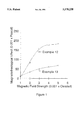
- FIG. 1 is a plot of magnetorheological effect at 25° C. as a function of magnetic field strength for magnetorheological materials prepared in accordance with Example 12 and comparative Example 13.
- the present invention relates to a magnetorheological material comprising a carrier fluid and a particle component wherein the particle component has been modified so that the surface of the particle component is substantially free of contamination products.
- the contamination products can essentially be any foreign material present on the surface of the particle and the contamination products are typically corrosion products.
- the formation of corrosion products on the surface of a magnetically active particle results from both chemical and electrochemical reactions of the particle's surface with water and atmospheric gases, as well as with electrolytes and particulates or contaminants that are either present in the atmosphere or left as a residue during particle preparation or processing.
- Examples of atmospheric gases involved in this surface degradation process include O 2 , SO 2 , H 2 S, NH 3 , NO 2 , NO, CS 2 , CH 3 SCH 3 , and COS.
- a metal may resist attack by one or more of these atmospheric gases, the surface of a metal is typically reactive towards several of these gases.
- Examples of chemical elements contaminating the surface of metal particles resulting from known powder processing techniques and methods include carbon, sulfur, oxygen, phosphorous, silicon and manganese.
- Examples of atmospheric particulates or contaminants involved in the formation of corrosion products on various metals include dust, water or moisture, dirt, carbon and carbon compounds or soot, metal oxides, (NH 4 )SO 4 , various salts (i.e., NaCl, etc.) and corrosive acids, such as hydrochloric acid, sulfuric acid, nitric acid and chromic acid. It is normal that metallic corrosion takes place in the presence of a combination of several of these atmospheric gases and contaminants.
- Corrosion products can either be compact and strongly adherent to the surface of the metal or loosely bound to the surface of the metal as a powder, film, flake or scale.
- the most common types of corrosion products include various forms of a metallic oxide layer, which are sometimes referred to as rust, scale or mill scale.
- the present invention is based on the discovery that the removal of contamination products from the surface of a magnetically polarizable particle causes the particle to be particularly effective in creating a magnetorheological material which is capable of exhibiting high yield stresses. Contamination products can be efficiently removed from the surface of metallic particles through abrader processing, chemical treatment or a combination thereof. In order to be effective, these techniques must be employed during the preparation of the magnetorheological material (in situ) or immediately prior to either the preparation of the magnetorheological material or the application of a particle barrier layer or coating.
- Abrader processing involves the physical or mechanical removal of the contamination products resulting from impacting the surface of the magnetically active particles at a high velocity with an abrasive media.
- This abrasive media can either be an abrasive additive to the magnetorheological material or a form of grinding media used only as a processing aid.
- the abrasive additive of the invention must be a material capable of sufficiently abrading a magnetorheological particle so as to substantially remove the contamination products from the surface of the particle.
- the abrasive additive must, therefore, possess a substantial degree of hardness or roughness so as to effectively abrade the surface of the magnetorheological particle.
- Various types of abrasive materials capable of removing contamination products from the surface of a metal are well known to those skilled in the art of tribology or superabrasives and can be utilized as abrasive additives in the invention.
- the abrasive additives of the invention are typically in the form of a powder and can be comprised of various materials such as the oxides of aluminum, chromium, zirconium, hafnium, titanium, silicon, and magnesium; the carbides, nitrides and borides of aluminum, silicon and boron; and cermets, such as WC-Co and Ni-Cr-Al 2 O 3 , as well as combinations thereof.
- abrasive additives include diamond dust, garnet, corundum, alumina, black mineral slag, Cr 2 O 3 , HfO 2 , TiO 2 , MgO, glass, sand, silica, aluminum silicates, pumice, rouge, emery, feldspar, SiC, B 4 C, BN, Si 3 N 4 , AlN, cerium oxide, and fused alumina, as well as other refractory or ceramic abrasives.
- Iron oxides have also been found to be effective as abrasive additives for purposes of the present invention. Specifically, it has been found that the relatively hard iron oxides can be utilized in combination with relatively soft iron powders such that the contamination products are removed from the surface of the iron by the iron oxides. It should be noted that although used in relatively minor amounts in the overall magnetorheological material, the iron oxides are magnetically active and also function as an additional magnetorheological particle in combination with the iron.
- the iron oxide includes all known pure iron oxides, such as Fe 2 O 3 and Fe 3 O 4 , well as those containing small amounts of other elements, such as manganese, zinc or barium. Specific examples of iron oxide include ferrites and magnetites with ferrites being preferred.
- the silica useful as an abrasive additive in the invention must be hydrophobic.
- the surface of the silica must be treated so as to contain a minimal amount of hydroxyl funtionality and the silica must be relatively free of adsorbed moisture. It is important that the surface of the silica be chemically treated to be hydrophobic since it has been found that conventional drying of otherwise hydrophilic silica (e.g., silica gel such as that supplied by PPG Industries under the trade name HI-SIL 233) is not sufficient to render the silica hydrophobic for purposes of the invention. Although not completely understood, it is believed that an excess of adsorbed moisture and/or hydroxyl functionality prevents the hydrophilic silica from sufficiently abrading the surface of the particle component.
- the hydrophobic silica of the invention can be prepared by reacting the hydroxyl groups on the surface of the silica with various organofunctional monomeric silanes or silane coupling agents, such as hydroxysilanes, acyloxysilanes, epoxysilanes, oximesilanes, alkoxysilanes, chlorosilanes and aminosilanes as is known in the art.
- the hydroxyl groups on the surface of the silica may also be reacted with polymeric compounds such as silicone oils, mineral oils and paraffin oils.
- the modification of the surface of silica with various materials to render the silica hydrophobic is described by W.
- hydrophobic silicas include those commercially obtainable under the trade names AEROSIL and CABOSIL from Degussa Corporation and Cabot Corporation, respectively.
- the preferred abrasive additives of the present invention include hydrophobic silica, iron oxides, and alumina because of their potential to contribute to the formation of a thixotropic network as described hereinafter. Iron oxides are specifically preferred due to their magnetorheological activity and relatively high specific gravity.
- the diameter of the abrasive additives utilized herein can range from about 0.001 to 50.0 ⁇ m, preferably from about 0.001 to 20.0 ⁇ m with about 0.001 to 5.0 ⁇ m being specifically preferred.
- These abrasive additives are typically utilized in an amount ranging from about 0.05 to about 10.0, preferably from about 0.1 to about 5.0, with about 0.2 to about 3.0 percent by volume of the total magnetorheological material being especially preferred.
- the abrasive additive In order to be effective, the abrasive additive must be caused to impact the surface of a magnetorheological particle with a kinetic energy high enough to efficiently remove contamination products from the surface of the particle. This can be carried out during the preparation of the magnetorheological material (in situ), immediately prior to the preparation of the magnetorheological material or immediately prior to the application of a protective coating to the particle.
- the abrasive additive is combined with the magnetotheological particle component, carrier fluid and any optional ingredients, and the resulting combination of ingredients is initially mixed by hand with a spatula or the like and then more thoroughly mixed with a homogenizer, mechanical mixer, mechanical shaker, or an appropriate milling device such as a ball mill, sand mill, attritor mill, colloid mill, paint mill, pebble mill, shot mill, vibration mill, roll mill, horizontal small media mill, or the like (all hereinafter collectively referred to as "mixing devices").
- the mass of the abrasive additive, as well as the velocity achieved by this additive during the mixing or dispersing process determines the magnitude of kinetic energy available for the removal of contamination products from the magnetorheological particles.
- the velocity of the abrasive additive is dependent upon the viscosity of the magnetorheological material and the speed at which the mixing device is operated. For a typical magnetorheological material with a viscosity less than about 1000 centipoise at 25° C., sufficient velocity is achieved by the abrasive additive to effectively remove contamination products from the magnetorheological particles when the mixing device is operated with a minimum tip speed of about 50 ft/min.
- the ingredients must be mixed together or dispersed for a sufficient length of time to substantially remove contamination products from the surface of the magentorheological particle.
- An increase in the velocity of the abrasive additive will usually result in a decrease in the required mixing or dispersion time.
- the ingredients should be mixed for a period of time typically ranging from about 1 minute to 24 hours, preferably ranging from about 5 minutes to 18 hours.
- a certain amount of experimentation may be required to determine the optimum parameters that will allow for efficient removal of contamination products from a particular magnetorheological particle. Even if the above guidelines with respect to mixing speed and mixing time are not precisely followed, the mere presence of an abrasive additive during the preparation and utilization of a magnetorheological material has been found to be beneficial in that contamination products are substantially reduced.
- the present invention therefore also relates to an electrorheological material comprising a carrier fluid, a magnetically active particle, and an abrasive additive wherein the particle has a diameter ranging from about 0.1 to 500 ⁇ m.
- the abrasive additive to be included in the electrorheological material can be any of the abrasive additives described above and is typically utilized in an amount ranging from about 0.05 to 10.0, preferably from about 0.1 to 5.0, with about 0.2 to 3.0 percent by volume of the total magnetorheological material being especially preferred.
- Confirmation of the substantial removal of contamination products from the surface of a magnetorheological particle may be obtained by utilizing various material characterization techniques known to those skilled in the art of analytical chemistry and surface analysis.
- Examples of several known techniques for the quantitative/qualitative detection of atomic and/or molecular species include neutron activation analysis; scanning ion mass spectrometry (SIMS); x-ray methods, such as x-ray powder diffraction, x-ray fluorescence spectroscopy (XRF), x-ray photoelectron spectroscopy (XPS) and electron spectroscopy for chemical analysis (ESCA); and microscopy methods, such as scanning tunneling microscopy (STM), scanning electron microscopy (SEM), scanning auger microanalysis (SAM), and electron probe microanalysis (EPMA).
- Microscopy of powder samples are typically performed using an ultramicrotomy procedure well known to those skilled in the art.
- the above mixing procedure is followed except that only the magnetorheological particle and abrasive additive are utilized.
- the abraded particle may be immediately combined with the other ingredients to prepare a magnetorheological material or immediately coated with a protective coating to prevent the reformation of corrosion products.
- the abraded particle is combined with the other ingredients of the magnetorheological material or coated with a protective coating within no more than about 60 minutes, preferably within no more than about 30 minutes, after completion of the mixing procedure, unless the particles are stored for a longer time period under a contaminant-free atmosphere.
- Contamination products can also be removed from the particle component through abrader processing using various grinding media as a processing aid.
- This form of abrader processing can also be performed during the preparation of the magnetorheological material or immediately prior to either preparing the magnetorheological material or applying a protective coating to the particles.
- the type of grinding media and the nature of the corresponding equipment needed to perform this abrading process are described as those capable of reducing or changing the diameter or size of the particle component. Specific types of appropriate media and equipment are well known to those skilled in the art of manufacturing paints and coatings.
- Devices such as homogenizers, mechanical mixers and shakers that do not utilize a milling-type process, and are therefore not capable of reducing particle size, provide inadequate removal of contamination products from the surface of magnetorheological particles for purposes of the present invention, unless an abrasive additive as previously described is utilized in combination with the device.
- Examples of common grinding media appropriate for use as a processing aid include balls, beads, pellets, pebbles, grit or shot comprised of various materials including stainless steel, ceramic, porcelain, flint, high carbon steel, high manganese steel, cast nickel alloy, low carbon forged steel, tungsten carbide, glass, zirconium silicate, zirconium oxide, and aluminum oxide.
- Examples of common media milling devices or mills that utilize these types of grinding media include sand mills, ball mills, attritor mills, pebble mills, shot mills, vibration mills and horizontal small media mills.
- the grinding media may be in the form of a wheel, disc or blade, such as that typically used in roll mills. A more complete description of media mills is provided by G.
- the grinding media must be caused to impact the surface of a magnetorheological particle with a kinetic energy high enough to sufficiently remove contamination products from the surface of the particle. It is the mass of the grinding media, as well as the velocity achieved by this media during the milling process that determines the magnitude of kinetic energy available for the removal of contamination products from the magnetorheological particles.
- the velocity of the grinding media is dependent upon the viscosity of the magnetorheological material and the speed at which the milling device is operated.
- the grinding media For a typical magnetorheological material with a viscosity less than about 1000 centipoise at 25° C., sufficient velocity is achieved by the grinding media to effectively remove contamination products from the magnetorheological particles when the milling device is operated with a minimum tip speed of about 300 ft/min.
- the ingredients must be mixed together or dispersed for a sufficient length of time to substantially remove contamination products from the surface of the magentorheological particle. An increase in the velocity of the grinding media will usually result in a decrease in the required milling time.
- the ingredients should be mixed for a period of time typically ranging from about 1 hour to 48 hours, preferably ranging from about 2 hours to 24 hours. A certain amount of experimentation may be required to determine the optimum parameters that will allow for efficient removal of contamination products from a particular magnetorheological particle.
- abrasive additives can be utilized in combination with grinding media and, in this case, the efficiency of the corresponding milling device may be increased resulting in a lesser amount of both time and speed of the milling device needed to remove the contamination products from the surface of the magnetorheological particle.
- Removal of contamination products from the surface of the magnetorheological particle can also be accomplished through chemical treatment techniques.
- the chemical treatment can be carried out during the preparation of the magnetorheological material (in situ), immediately prior to the preparation of the magnetorheological material or immediately prior to the application of a protective coating to the particle.
- Chemical treatment methods or techniques applicable to the removal of contamination products during the preparation of the magnetorheological material include acid cleaning, alkaline cleaning, electrolytic cleaning, ultrasonic cleaning and combinations thereof, such as the combination of electrolytic cleaning and alkaline cleaning commonly utilized in the electroplating industry.
- alkaline cleaners useful in the invention include alkali metal orthophosphates, condensed phosphates, hydroxides, carbonates, bicarbonates, silicates and borates. Alkaline cleaners are typically utilized in combination with a surfactant as is known in the art.
- Examples of common acid cleaners useful in the invention include organic acids, such as citric, tartaric, acetic, oxalic and gluconic acid, acid salts, such as sodium phosphate, ammonium persulfate, sodium acid sulfate and bifluroride salts, and inorganic acids, such as sulfuric acid, phosphoric acid and hydrochloric acid.
- organic acids such as citric, tartaric, acetic, oxalic and gluconic acid
- acid salts such as sodium phosphate, ammonium persulfate, sodium acid sulfate and bifluroride salts
- inorganic acids such as sulfuric acid, phosphoric acid and hydrochloric acid.
- Acid and alkaline cleaning during the preparation of the magnetorheological material can be carried out by adding an acid or alkaline cleaner to the ingredients utilized to prepare the magnetorheological material and then thoroughly mixing the ingredients first by hand with a spatula or the like and then with a mechanical mixing device.
- the acid or alkaline cleaner is typically utilized in an amount ranging from about 0.1 to 5.0, preferably from about 0.5 to 3.0, percent by weight of the particle component.
- Electrolytic cleaning or electrocleaning during the preparation of the magnetorheological material is typically carried out by applying an electric current to the material in order to produce vigorous gassing on the surface of the particles and promote the release of contaminants.
- Electrocleaning can be either cathodic or anodic in nature. This technique is generally used in conjunction with acid or alkaline cleaning as previously described.
- Ultrasonic cleaning during the preparation of the magnetorheological material is typically carried out by passing sound waves at high frequencies through the material. These ultrasonic waves create tiny gas bubbles throughout the carrier component, which vigorously cleans the surface of the particles. This technique is often used in conjunction with acid or alkaline cleaning as previously described.
- the chemical treatment methods that are applicable to the removal of contamination products immediately prior to either preparing the magnetorheological material or applying a protective coating include the techniques described above for in situ treatment, as well as metal reduction; plasma cleaning; ion etching; sputter cleaning and combinations thereof.
- Metal reduction typically involves the reduction of the metal particle's surface through a reaction with a gaseous molecule, such as hydrogen, at elevated temperatures.
- the preferred chemical treatment method of the invention is the utilization of acid cleaners or alkaline cleaners during the preparation of the magnetorheological material (in situ).
- the present invention therefore also relates to a magnetorheological material comprising a carrier fluid, a magnetically active particle, and an acid cleaner or an alkaline cleaner wherein the particle has a diameter ranging from about 0.1 to 500 ⁇ m.
- the acid or alkaline cleaner useful in the magnetorheological material can be any of the acid or alkaline cleaners described above and is typically utilized in an amount ranging from about 0.1 to 5.0, preferably from about 0.5 to 3.0 percent by weight of the particle component.
- abrasive additives for purposes of the present invention, abrasive additives, acid cleaners and alkaline cleaners are herein collectively referred to as contaminant-removing additives.
- a protective coating can be applied to the surface of the particle.
- the protective coating substantially, preferably entirely, encase or encapsulate the particle.
- Protective coatings that substantially encapsulate the particle are to be distinguished from insulation coatings, such as those presently found on carbonyl iron powder such as the insulated reduced carbonyl iron powder supplied by GAF Corporation under the designations "GQ-4" and "GS-6.”
- the insulation coatings found on insulated reduced carbonyl iron are intended to prevent particle-to-particle contact and are simply formed by dusting the particles with silica gel particulates. Insulation coatings therefore do not substantially encapsulate the particle so as to prevent the formation of contamination products.
- the sporadic coverage of a particle's surface by an insulation coating can be seen in the scanning electron micrographs presented in the article by J. Japka entitled "Iron Powder for Metal Injection Molding" (International Journal of Powder Metallurgy, 27(2), 107-114), the entire contents of which are incorporated herein by reference. Incomplete coverage of the particle's surface by a coating typically will result in the accelerated formation of contamination products through the process described above for solid atmospheric particles, such as dust and soot.
- Iron oxide previously described in the literature as being useful as an insulation coating, cannot be used as a protective coating for purposes of the present invention because iron oxide itself is a corrosion product.
- the protective coatings of the invention that are effective in preventing the formation of contamination products on the surface of magnetorheological particles can be composed of a variety of materials including nonmagnetic metals, ceramics, thermoplastic polymeric materials, thermosetting polymers and combinations thereof.
- thermosetting polymers useful for forming a protective coating include polyesters, polyimides, phenolics, epoxies, urethanes, rubbers and silicones, while thermoplastic polymeric materials include acrylics, cellulosics, polyphenylene sulfides, polyquinoxilines, polyetherimides and polybenzimidazoles.
- Typical nonmagnetic metals useful for forming a protective coating include refractory transition metals, such as titanium, zirconium, hafnium, vanadium, niobium, tantulum, chromium, molybdenum, tungsten, copper, silver, gold, and lead, tin, zinc, cadmium, cobalt-based intermetallic alloys, such as Co-Cr-W-C and Co-Cr-Mo-Si, and nickel-based intermetallic alloys, such as Ni-Cu, Ni-Al, Ni-Cr, Ni-Mo-C, Ni-Cr-Mo-C, Ni-Cr-B-Si-C, and Ni-Mo-Cr-Si.
- transition metals such as titanium, zirconium, hafnium, vanadium, niobium, tantulum, chromium, molybdenum, tungsten, copper, silver, gold, and lead, tin, zinc, cadmi
- Ceramic materials useful for forming a protective coating include the carbides, nitrides, borides, and silicides of the refractory transition metals described above; nonmetallic oxides, such as Al 2 O 3 , Cr 2 O 3 , ZrO 3 , HfO 2 , TiO 2 , SiO 2 , BeO, MgO, and ThO 2 ; nonmetallic nonoxides, such as B 4 C, SiC, BN, Si 3 N 4 , AlN, and diamond; and various cermets.
- nonmetallic oxides such as Al 2 O 3 , Cr 2 O 3 , ZrO 3 , HfO 2 , TiO 2 , SiO 2 , BeO, MgO, and ThO 2
- nonmetallic nonoxides such as B 4 C, SiC, BN, Si 3 N 4 , AlN, and diamond
- various cermets such as B 4 C, SiC, BN, Si 3 N 4 , AlN, and diamond.
- the protective coatings of the invention can be applied by techniques or methods well known to those skilled in the art of tribology. Examples of common coating techniques include both physical deposition and chemical vapor deposition methods. Physical deposition techniques include both physical vapor deposition and liquid or wetting methods. Physical vapor deposition methodology includes direct, reactive, activated reactive and ion-beam assisted evaporation; DC/RF diode, alternating, triode, hollow cathode discharge, sputter ion, and cathodic arc glow discharge ion plating; direct, cluster ion and ion beam plating; DC/RF diode, triode and magnetron glow discharge sputtering; and single and dual ion beam sputtering.
- Common physical liquid or wetting methodology includes air/airless spray, dip, spin-on, electrostatic spray, spray pyrolysis, spray fusion, fluidized bed, electrochemical deposition, chemical deposition such as chemical conversion (e.g., phosphating, chromating, metalliding, etc.), electroless deposition and chemical reduction; intermetallic compounding, and colloidal dispersion or sol-gel coating application techniques.
- Chemical vapor deposition methodology includes conventional, low pressure, laser-induced, electron-assisted, plasma-enhanced and reactive-pulsed chemical vapor deposition, as well as chemical vapor polymerization. A thorough discussion of these various coating processes is provided in Bhushan.
- the preferred abrader processing and chemical treatment methods of the invention include those performed during the preparation of the magnetorheological material.
- abrader processing is generally preferable over chemical treatment.
- the protective coating applied to a particle in an "as received" condition prevents the further degradation of the properties associated with the particle.
- This protective coating may also provide additional advantages to the formulated magnetorheological material by reducing wear associated with seals and other device components that are in contact with the magnetorheological material, as well as increasing the mechanical durability of the particle component.
- the present invention relates to a magnetorheological material comprising a carrier fluid and a magnetically active particle wherein the particle is substantially encapsulated or coated with a protective coating and has a diameter ranging from about 0.1 to 500 ⁇ m.
- the protective coating applied to the surface of the particle of the magnetorheological material may be any of the protective coatings described above and may be applied by any of the methods described above.
- the protective coating cover or encapsulate at least about 90 percent, preferably from about 95 to 100 percent, and most preferably from about 98 to 100 percent of the surface of the particle in order to provide adequate protection from corrosion and wear.
- protective coatings that substantially encapsulate a particle are distinguishable from traditional insulation coatings such as those presently found on carbonyl iron powder.
- the magnetically active particle component to be modified according to the present invention can be comprised of essentially any solid which is known to exhibit magnetorheological activity and which can inherently form a contamination product on its surface.
- Typical particle components useful in the present invention are comprised of, for example, paramagnetic, superparamagnetic, or ferromagnetic compounds.
- Specific examples of particle components useful in the present invention include particles comprised of materials such as iron, iron nitride, iron carbide, carbonyl iron, chromium dioxide, low carbon steel, silicon steel, nickel, cobalt, and mixtures thereof.
- the particle component can be comprised of any of the known alloys of iron, such as those containing aluminum, silicon, cobalt, nickel, vanadium, molybdenum, chromium, tungsten, manganese and/or copper.
- the particle component can also be comprised of the specific iron-cobalt and iron-nickel alloys described in the U.S. patent application entitled “Magnetorheological Materials Based on Alloy Particles" filed concurrently herewith by Applicants J. D. Carlson and K. D. Weiss and also assigned to the present assignee, the entire disclosure of which is incorporated herein by reference.
- the particle component is typically in the form of a metal powder which can be prepared by processes well known to those skilled in the art. Typical methods for the preparation of metal powders include the reduction of metal oxides, grinding or attrition, electrolytic deposition, metal carbonyl decomposition, rapid solidification, or smelt processing. Various metal powders that are commercially available include straight iron powders, reduced iron powders, insulated reduced iron powders, and cobalt powders.
- the diameter of the particles utilized herein can range from about 0.1 to 500 ⁇ m and preferably range from about 1.0 to 50 ⁇ m.
- the preferred particles of the present invention are straight iron powders, reduced iron powders, iron-cobalt alloy powders and iron-nickel alloy powders.
- the particle component typically comprises from about 5 to 50, preferably about 15 to 40, percent by volume of the total composition depending on the desired magnetic activity and viscosity of the overall material.
- the carrier fluid of the magnetorheological material of the present invention can be any carrier fluid or vehicle previously disclosed for use in magnetorheological materials, such as the mineral oils, silicone oils and paraffin oils described in the patents set forth above.
- Additional carrier fluids appropriate to the invention include silicone copolymers white oils, hydraulic oils, chlorinated hydrocarbons, transformer oils, halogenated aromatic liquids, halogenated paraffins, diesters, polyoxyalkylenes, perflurorinated polyethers, flurorinated hydrocarbons, flurorinated silicones, and mixtures thereof.
- transformer oils refer to those liquids having characteristic properties of both electrical and thermal insulation.
- Naturally occurring transformer oils include refined mineral oils that have low viscosity and high chemical stability.
- Synthetic transformer oils generally comprise chlorinated aromatics (chlorinated biphenyls and tfichlorobenzene), which are known collectively as “askarels", silicone oils, and esteric liquids such as dibutyl sebacates.
- the preferred carrier fluids of the present invention are silicone oils and mineral oils.
- the carrier fluid of the magnetorheological material of the present invention should have a viscosity at 25° C. that is between about 2 and 1000 centipoise, preferably between about 3 and 200 centipoise, with a viscosity between about 5 and 100 centipoise being especially preferred.
- the carrier fluid of the present invention is typically utilized in an amount ranging from about 50 to 95, preferably from about 60 to 85, percent by volume of the total magnetorheological material.
- a thixotropic network is defined as a suspension of particles that, at low shear rates, form a loose network or structure sometimes referred to as clusters or flocculates.
- the presence of this three-dimensional structure imparts a small degree of rigidity to the magnetorheological material, thereby reducing particle settling.
- this structure is easily disrupted or dispersed. When the shearing force is removed, this loose network is reformed over a period of time.
- a thixotropic network may be formed in the magnetorheological fluid of the present invention through the utilization of any known hydrogen-bonding thixotropic agents and/or colloidal additives.
- the thixotropic agents and colloidal additives, if utilized, are typically employed in an amount ranging from about 0.1 to 5.0, preferably from about 0.5 to 3.0, percent by volume relative to the overall volume of the magnetorheological fluid.
- Examples of hydrogen-bonding thixotropic agents useful for forming a thixotropic network in the present invention include low molecular weight hydrogen-bonding molecules, such as water and other molecules containing hydroxyl, carboxyl or amine functionality, as well as medium molecular weight hydrogen-bonding molecules, such as silicone oligomers, organosilicone oligomers, and organic oligomers.
- Typical low molecular weight hydrogen-bonding molecules other than water include alcohols; glycols; alkyl amines, amino alcohols, amino esters, and mixtures thereof.
- Typical medium molecular weight hydrogen-bonding molecules include oligomers containing sulphonated, amino, hydroxyl, cyano, halogenated, ester, carboxylic acid, ether, and ketone moieties, as well as mixtures thereof.
- colloidal additives useful for forming a thixotropic network in the present invention include hydrophobic and hydrophilic metal oxide and high molecular weight powders.
- hydrophobic powders include surface-treated hydrophobic fumed silica and organoclays.
- hydrophilic metal oxide or polymeric materials include silica gel, fumed silica, clays, and high molecular weight derivatives of caster oil, poly(ethylene oxide), and poly(ethylene glycol).
- An additional surfactant to more adequately disperse the particle component may be optionally utilized in the present invention.
- Such surfactants include known surfactants or dispersing agents such as ferrous oleate and naphthenate, sulfonates, phosphate esters, glycerol monooleate, sorbitan sesquioleate, stearates, laurates, fatty acids, fatty alcohols, and the other surface active agents discussed in U.S. Pat. No. 3,047,507 (incorporated herein by reference).
- Alkaline soaps, such as lithium stearate and sodium stearate, and metallic soaps, such as aluminum tristearate and aluminum distearate can also be presently utilized as a surfactant.
- the optional surfactants may be comprised of steric stabilizing molecules, including fluoroaliphatic polymeric esters, such as FC-430 (3M Corporation), and titanate, aluminate or zirconate coupling agents, such as KEN-REACT® (Kenrich Petrochemicals, Inc.) coupling agents.
- a precipitated silica gel such as that disclosed in U.S. Pat. No. 4,992,190 (incorporated herein by reference), can be used to disperse the particle component. In order to reduce the presence of moisture in the magnetorheological material, it is preferred that the precipitated silica gel, if utilized, be dried in a convection oven at a temperature of from about 110° C. to 150° C. for a period of time from about 3 to 24 hours.
- the surfactant if utilized, is preferably a "dried" precipitated silica gel, a fluoroaliphatic polymeric ester, a phosphate ester, or a coupling agent.
- the optional surfactant may be employed in an amount ranging from about 0.1 to 20 percent by weight relative to the weight of the particle component.
- the magnetorheological materials of the present invention may also contain other optional additives such as lubricants or anti-wear agents, pour point depressants, viscosity index improvers, foam inhibitors, and corrosion inhibitors. These optional additives may be in the form of dispersions, suspensions or materials that are soluble in the carrier fluid of the magnetorheological material.
- the preparation of magnetorheological materials according to the invention where contamination products are removed from the surface of the magnetorheological particle in situ has previously been described. If contamination products are removed from the particle immediately prior to either the preparation of the magnetorheological material or the application of a protective coating, the magnetorheological materials of the present invention can be prepared by simply mixing together the carrier fluid, the pre-treated particle component, and any optional ingredients.
- the ingredients of the magnetorheological materials may be initially mixed together by hand with a spatula or the like and then subsequently more thoroughly mixed with a homogenizer, mechanical mixer, mechanical shaker, or an appropriate milling device such as a ball mill, sand mill, attritor mill, colloid mill, paint mill, pebble mill, shot mill, vibration mill, roll mill, horizontal small media mill or the like, in order to create a more stable suspension.
- a homogenizer such as a ball mill, sand mill, attritor mill, colloid mill, paint mill, pebble mill, shot mill, vibration mill, roll mill, horizontal small media mill or the like.
- the mixing conditions for the preparation of a magnetorheological material utilizing a magnetorheological particle that has had contamination products previously removed can be somewhat less rigorous than the conditions required for the preparation and in situ removal of contamination products.
- the dynamic yield stress for the magnetorheological material corresponds to the zero-rate intercept of a linear regression curve fit to the measured data.
- the magnetorheological effect at a particular magnetic field can be further defined as the difference between the dynamic yield stress measured at that magnetic field and the dynamic yield stress measured when no magnetic field is present.
- the viscosity for the magnetorheological material corresponds to the slope of a linear regression curve fit to the measured data.
- the magnetorheological material is placed in the annular gap formed between an inner cylinder of radius R 1 and an outer cylinder of radius R 2 , while in a simple parallel plate configuration the material is placed in the planar gap formed between upper and lower plates both with a radius, R 3 .
- either one of the plates or cylinders is then rotated with an angular velocity ⁇ while the other plate or cylinder is held motionless.
- a magnetic field can be applied to these cell configurations across the fluid-filled gap, either radially for the concentric cylinder configuration, or axially for the parallel plate configuration.
- the relationship between the shear stress and the shear strain rate is then derived from this angular velocity and the torque, T, applied to maintain or resist it.
- Example 1 a magnetorheological material is prepared by slowly adding a total of 117.9 g of carbonyl iron powder (Sigma Chemical Company) to a mixture of 3.54 g of an 11N phosphoric acid solution, which is prepared using phosphoric acid (99%, Aldrich Chemical Company) and distilled water, and 28.29 g of 20 cstk mineral oil (DRAKEOL 10, Pennzoil Products Company). The temperature of the magnetorheological material is maintained during this initial mixing procedure within the temperature range of about 30° to 45° C.
- the fluid is initially mixed by hand with a spatula (low shear) and then more thoroughly dispersed into a homogeneous mixture through the use of a high speed disperserator (high shear) equipped with a 16-tooth rotary head.
- the weight amount of the chemically treated iron particles in the magnetorheological material is equivalent to a volume fraction of about 0.30.
- the magnetorheological material is stored in a polyethylene container.
- Example 2 a magnetorheological material is prepared according to the procedure described in Example 1. However, in this example the phosphoric acid solution is replaced with 3.54 g of an 11N sulfuric acid solution, which is prepared using sulfuric acid (95-98%, Aldrich Chemical Company) and distilled water. The amount of mineral oil is adjusted to maintain the particle volume fraction in the magnetorheological material at 0.30. The magnetorheological material is stored in a polyethylene container.
- Example 3 a magnetorheological material is prepared according to the procedure described in Example 1. However, in this example a total of 117.9 g of carbonyl iron powder (Sigma Chemical Company), 2.35 g of stearic acid (Aldrich Chemical Company) as a dispersant and 28.67 g of 20 cstk mineral oil (DRAKEOL 10, Pennzoil Products Company) are mixed together. The weight amount of untreated iron particles in the magnetorheological material is equivalent to a volume fraction of about 0.30. The conventional magnetorheological material is stored in a polyethylene container.
- the magnetorheological materials prepared in Examples 1, 2 and 3 are evaluated through the use of parallel plate rheometry. A summary of the magnetorheological effect observed for these magnetorheological materials at various magnetic field strengths and 25° C. is provided in Table 1. A significantly higher magnetorheological effect is observed for the magnetorheological materials utilizing particles wherein contamination products have been removed by chemical treatment (Examples 1 and 2) as compared to a magnetorheological material containing conventional untreated particles (Example 3). At a magnetic field strength of 5000 Oersted the magnetorheological effect exhibited by the magnetorheological materials containing the chemically treated particles is about 71% greater than that exhibited by a conventional magnetorheological material.
- a magnetorheological material is prepared by mixing together a total of 123.2 g of carbonyl iron powder (Sigma Chemical Company), 2.46 g of stearic acid (Aldrich Chemical Company) as a dispersant and 34.20 g of 200 cstk silicone oil (Dow Corning Corporation). This weight amount of iron particles is equivalent to a volume fraction in the magnetorheological material of about 0.30.
- the fluid is made into a homogeneous mixture using an Union Process 01HD attritor mill equipped with a 110 cm 3 tank.
- the grinding media used in this attritor mill is in the form of stainless steel balls. This mill has the capability to reduce the mean size and distribution of the particle component when the impacting grinding media has high kinetic energy.
- This grinding media imparts sufficient kinetic energy to remove the contamination products from the particle component when the agitator shaft and arms of this mill are rotated at tip speed of about 300 ft./min.
- the maximum tip speed of this mill is measured to be about 600 ft./min.
- the magnetorheological material is aggressively milled in this abrader process over a 48-hour period with a tip speed of about 445 ft./min.
- the magnetorheological material is separated from the grinding media and stored in a polyethylene container.
- a magnetorheological material is prepared according to the procedure described in Example 4. However, in this example the mill is operated with a tip speed of about 250 ft./min. over a 96-hour period. The rotation of the agitator shaft and arms at this angular speed does not impart sufficient kinetic energy to the stainless steel grinding media to remove the contamination products from the surface of particle component.
- the conventional magnetorheological material is separated from the grinding media and stored in a polyethylene container.
- the magnetorheological materials prepared in Examples 4 and 5 are evaluated through the use of parallel plate rheometry. A summary of the magnetorheological effect for these magnetorheological materials at various magnetic field strengths and 25° C. is provided in Table 2. A significantly higher magnetorheological effect is observed for the magnetorheological material utilizing particles wherein contamination products have been removed by stainless steel grinding media in an abrader process (Example 4) as compared to a magnetorheological material containing conventional particles (Example 5). At a magnetic field strength of 3000 Oersted the magnetorheological effect exhibited by the magnetorheological material containing the abrader process modified particles is about 69% greater than that exhibited by a conventional magnetorheological material.
- a magnetorheological material is prepared by adding together a total of 117.9 g of reduced iron powder (ATOMET 95G, Quebec Metal Powders Limited), 8.75 g of Mn/Zn ferrite powder (#73302-0, D. M. Steward Manufacturing Company) as an abrasive additive, 2.53 g polyoxyethylene/silicone graft copolymer (SILWET L7500, Union Carbide Chemicals and Plastics Company, Inc.) as a thixotropic agent and 29.13 g of 10 cstk silicone oil (L-45, Union Carbide Chemicals and Plastics Company, Inc.).
- the fluid is initially mixed by hand with a spatula (low shear) and then more thoroughly dispersed into a homogeneous mixture through the use of a high speed disperserator (high shear) equipped with a 16-tooth rotary head and operated at a tip speed of about 400 ft./min. for about 5 minutes.
- the weight amount of the iron particles in the magnetorheological material is equivalent to a volume fraction of about 0.30.
- the presence of the abrasive ferrite powder in this magnetorheological material efficiently removes the contamination products from the surface of the iron particles.
- the magnetorheological material whose particle component has been modified by abrader processing is stored in a polyethylene container.
- a magnetorheological material is prepared according to the procedure described in Example 6 with the exception that the abrasive ferrite powder is excluded.
- the weight amount of the oil component is modified to maintain an iron particle volume fraction in the magnetorheological material of 0.30.
- This conventional magnetorheological material is stored in a polyethylene container.
- the magnetorheological materials prepared in Examples 6 and 7 are evaluated through the use of parallel plate rheometry. A summary of the magnetorheological effect observed for these magnetorheological materials at various magnetic field strengths and 25° C. is provided in Table 3. A significantly higher magnetorheological effect is observed for the magnetorheological material utilizing particles wherein contamination products have been removed by the presence of an abrasive additive in an abrader process (Example 6) as compared to a magnetorheological material containing conventional particles (Example 7). At a magnetic field strength of 5000 Oersted the magnetorheological effect exhibited by the magnetorheological material containing the abrader process modified particles is about 147% greater than that exhibited by a conventional magnetorheological material.
- Example 8 a magnetorheological material is prepared by adding together a total of 117.9 g of straight carbonyl iron powder (MICROPOWDER S-1640, GAF Chemicals Corporation), 1.18 g of Boron Carbide (99%, Johnson Matthey Company) as an abrasive additive, 2.36 g organomodifed polydimethylsiloxane copolymer (SILWET L7500, Union Carbide Chemicals and Plastics, Company, Inc.) as a hydrogen-bonding thixotropic agent and 27.55 g of 10 cstk silicone oil (L-45, Union Carbide Chemicals and Plastics Company, Inc.).
- MICROPOWDER S-1640 straight carbonyl iron powder
- Boron Carbide 99%, Johnson Matthey Company
- SILWET L7500 organomodifed polydimethylsiloxane copolymer
- SILWET L7500 organomodifed polydimethylsiloxane copolymer
- the fluid is initially mixed by hand with a spatula (low shear) and then more thoroughly dispersed into a homogeneous mixture through the use of a high speed disperserator (high shear) equipped with a 16-tooth rotary head and operated at a tip speed of about 400 ft./min. for about 5 minutes.
- the weight amount of the iron particles in the magnetorheological material is equivalent to a volume fraction of about 0.32.
- the presence of the abrasive additive in this magnetorheological material efficiently removes the contamination products from the surface of the iron particles.
- the magnetorheological material whose particle component has been modified by abrader processing is stored in a polyethylene container.
- Magnetorheological materials are prepared in Examples 9 and 10 according to the procedure described for Example 8. However, in Example 9 the boron carbide powder is replaced with 1.51 g silicon carbide powder (alpha, 99.8%, Johnson Matthey Company) as an abrasive additive. In Example 10, the abrasive additive is replaced with 2.43 g iron (II, III) oxide powder (97%, Johnson Matthey Company). The weight amount of the iron particles in each of the magnetorheological materials is equivalent to a volume fraction of about 0.32. The magnetorheological materials whose particle component has been modified by abrader processing is stored in a polyethylene container.
- a magnetorheological material is prepared according to the procedure described in Example 8. However, in this case no abrasive additive is incorporated into the magnetorheological material. The amount of the carrier oil component is appropriately increased to insure that the volume fraction of iron particles in the magnetorheological material is about 0.32.
- the conventional magnetorheological material is stored in a polyethylene container.
- the magnetorheological materials prepared in Examples 8, 9, 10 and 11 are evaluated through the use of parallel plate rheometry.
- a summary of the magnetorheological effect observed for these magnetorheological materials at various magnetic field strengths and 25° C. is provided in Table 4.
- a significantly higher magnetorheological effect is observed for the magnetorheological materials utilizing particles wherein contamination products have been removed by the presence of an abrasive additive or iron oxide particles in an abrader process (Examples 8-10) as compared to a magnetorheological material containing conventional particles (Example 11).
- At a magnetic field strength of 3000 Oersted the magnetorheological effect exhibited by the magnetorheological material containing the abrader process modified particles is about 74% greater than that exhibited by a conventional magnetorheological material.
- a magnetorheological material is prepared by adding together a total of 117.9 g of reduced carbonyl iron powder (MICROPOWDER R-1430, GAF Chemicals Corporation), 1.90 g of hydrophobic fumed silica (CABOSIL TS-720, Cabot Corporation) and 29.95 g of 10 cstk silicone oil (L-45, Union Carbide Chemicals and Plastics Company, Inc.).
- the fluid is initially mixed by hand with a spatula (low shear) and then more thoroughly dispersed into a homogeneous mixture through the use of a high speed disperserator (high shear) equipped with a 16-tooth rotary head and operated at a tip speed of about 400 ft./min. for about 5 minutes.
- the weight amount of the iron particles in the magnetorheological material is equivalent to a volume fraction of about 0.32.
- the presence of the abrasive hydrophobic silica powder in this magnetorheological material efficiently removes the contamination products from the surface of the iron particles.
- the magnetorheological material whose particle component has been modified by abrader processing is stored in a polyethylene container.
- a magnetorheological material is prepared according to the procedure described in Example 12 with the exception that the hydrophobic silica powder is replaced with an identical amount of a hydrophilic silica gel dispersant (HI-SIL 233, PPG Industries).
- This silica gel dispersant which has previously been disclosed as a dispersant in U.S. Pat. No. 4,992,190, is dried in a convection oven at 130° C. for 24 hours prior to use.
- This magnetorheological material contains a particle volume fraction of 0.32.
- This conventional magnetorheological material is stored in a polyethylene container.
- the magnetorheological materials prepared in Examples 12 and 13 are evaluated through the use of parallel plate rheometry. A summary of the magnetorheological effect observed for these magnetorheological materials at various magnetic field strengths and 25° C. is provided in FIG. 1. A significantly higher magnetorheological effect is obtained for the magnetorheological material utilizing particles wherein contamination products have been removed by the presence of an abrasive hyrophobic silica additive in an abrader process (Example 12) as compared to a magnetorheological material containing conventional particles (Example 13). At a magnetic field strength of 5000 Oersted the magnetorheological effect exhibited by the magnetorheological material containing the abrader process modified particles is about 167% greater than that exhibited by a conventional magnetorheological material.
- magnetorheological materials that contain a particle component that has been modifed by the removal of inherent contamination products through chemical treatment or abrader processing exhibit a significantly higher magnetorheological effect than conventional magnetorheological materials.
Abstract
d
A magnetorheological material containing a carrier fluid and a magnetically active particle. The particle has been modified so that the surface of the particle is substantially free of contamination products. The contamination products are removed from the surface of the particle by abrader processing, chemical treatment or a combination thereof. Magnetorheological materials prepared using the particles from which contamination products have been removed exhibit significantly enhanced magnetorheological effects.
Description
This is a continuation-in-part of application(s) Ser. No. 07/959,687 filed Oct. 30, 1992 now abandoned.
The present invention relates to certain fluid materials which exhibit substantial increases in flow resistance when exposed to magnetic fields. More specifically, the present invention relates to magnetorheological materials that utilize a surface-modified particle component in order to enhance yield strength.
Fluid compositions which undergo a change in apparent viscosity in the presence of a magnetic field are commonly referred to as Bingham magnetic fluids or magnetorheological materials. Magnetorheological materials normally are comprised of ferromagnetic or paramagnetic particles, typically greater than 0.1 micrometers in diameter, dispersed within a carrier fluid and in the presence of a magnetic field, the particles become polarized and are thereby organized into chains of particles within the fluid. The chains of particles act to increase the apparent viscosity or flow resistance of the overall material and in the absence of a magnetic field, the particles return to an unorganized or free state and the apparent viscosity or flow resistance of the overall material is correspondingly reduced. These Bingham magnetic fluid compositions exhibit controllable behavior similar to that commonly observed for electrorheological materials, which are responsive to an electric field instead of a magnetic field.
Both electrorheological and magnetorheological materials are useful in providing varying damping forces within devices, such as dampers, shock absorbers and elastomeric mounts, as well as in controlling torque and or pressure levels in various clutch, brake and valve devices. Magnetorheological materials inherently offer several advantages over electrorheological materials in these applications. Magnetorheological fluids exhibit higher yield strengths than electrorheological materials and are, therefore, capable of generating greater damping forces. Furthermore, magnetorheological materials are activated by magnetic fields which are easily produced by simple, low voltage electromagnetic coils as compared to the expensive high voltage power supplies required to effectively operate electrorheological materials. A more specific description of the type of devices in which magnetorheological materials can be effectively utilized is provided in copending U.S. application Ser. Nos. 07/900,571 and 07/900,567 entitled "Magnetorheological Fluid Dampers" and "Magnetorheological Fluid Devices," respectively, both filed on Jun. 18, 1992, the entire contents of which are incorporated herein by reference.
Magnetorheological or Bingham magnetic fluids are distinguishable from colloidal magnetic fluids or ferrofiuids. In colloidal magnetic fluids the particles are typically 5 to 10 nanometers in diameter. Upon the application of a magnetic field, a colloidal ferrofluid does not exhibit particle structuring or the development of a resistance to flow. Instead, colloidal magnetic fluids experience a body force on the entire material that is proportional to the magnetic field gradient. This force causes the entire colloidal ferrofiuid to be attracted to regions of high magnetic field strength.
Magnetorheological fluids and corresponding devices have been discussed in various patents and publications. For example, U.S. Pat. No. 2,575,360 provides a description of an electromechanically controllable torque-applying device that uses a magnetorheological material to provide a drive connection between two independently rotating components, such as those found in clutches and brakes. A fluid composition satisfactory for this application is stated to consist of 50% by volume of a soft iron dust, commonly referred to as "carbonyl iron powder", dispersed in a suitable liquid medium such as a light lubricating oil.
Another apparatus capable of controlling the slippage between moving parts through the use of magnetic or electric fields is disclosed in U.S. Pat. No. 2,661,825. The space between the moveable parts is filled with a field responsive medium. The development of a magnetic or electric field flux through this medium results in control of resulting slippage. A fluid responsive to the application of a magnetic field is described to contain carbonyl iron powder and light weight mineral oil.
U.S. Pat. No. 2,886,151 describes force transmitting devices, such as clutches and brakes, that utilize a fluid film coupling responsive to either electric or magnetic fields. An example of a magnetic field responsive fluid is disclosed to contain reduced iron oxide powder and a lubricant grade oil having a viscosity of from 2 to 20 centipoises at 25° C.
The construction of valves useful for controlling the flow of magnetorheological fluids is described in U.S. Pat. Nos. 2,670,749 and 3,010,471. The magnetic fluids applicable for utilization in the disclosed valve designs include ferromagnetic, paramagnetic and diamagnetic materials. A specific magnetic fluid composition specified in U.S. Pat. No. 3,010,471 consists of a suspension of carbonyl iron in a light weight hydrocarbon oil. Magnetic fluid mixtures useful in U.S. Pat. No. 2,670,749 are described to consist of a carbonyl iron powder dispersed in either a silicone oil or a chlorinated or fluorinated suspension fluid.
Various magnetorheological material mixtures are disclosed in U.S. Pat. No. 2,667,237. The mixture is defined as a dispersion of small paramagnetic or ferromagnetic particles in either a liquid, coolant, antioxidant gas or a semi-solid grease. A preferred composition for a magnetorheological material consists of iron powder and light machine oil. A specifically preferred magnetic powder is stated to be carbonyl iron powder with an average particle size of 8 micrometers. Other possible carrier components include kerosene, grease, and silicone oil.
U.S. Pat. No. 4,992,190 discloses a rheological material that is responsive to a magnetic field. The composition of this material is disclosed to be magnetizable particles and silica gel dispersed in a liquid carrier vehicle. The magnetizable particles can be powdered magnetite or carbonyl iron powders with insulated reduced carbonyl iron powder, such as that manufactured by GAF Corporation, being specifically preferred. The liquid carrier vehicle is described as having a viscosity in the range of 1 to 1000 centipoises at 100° F. Specific examples of suitable vehicles include Conoco LVT oil, kerosene, light paraffin oil, mineral oil, and silicone oil. A preferred carrier vehicle is silicone oil having a viscosity in the range of about 10 to 1000 centipoise at 100° F.
In many demanding applications for magnetorheological materials, such as dampers or brakes for automobiles or trucks, it is desirable for the magnetorheological material to exhibit a high yield stress so as to be capable of tolerating the large forces experienced in these types of applications. It has been found that only a nominal increase in yield stress of a given magnetorheological material can be obtained by selecting among the different iron particles traditionally utilized in magnetorheological materials. In order to increase the yield stress of a given magnetorheological material, it is typically necessary to increase the volume fraction of magnetorheological particles or to increase the strength of the applied magnetic field. Neither of these techniques is desirable since a high volume fraction of the particle component can add significant weight to a magnetorheological device, as well as increase the overall off-state viscosity of the material, thereby restricting the size and geometry of a magnetorheological device capable of utilizing that material, and high magnetic fields significantly increase the power requirements of a magnetorheological device.
A need therefore exists for a magnetorheological particle component that will independently increase the yield stress of a magnetorheological material without the need for an increased particle volume fraction or increased magnetic field.
The present invention is a magnetorheological material comprising a carrier fluid and a magnetically active particle wherein the particle has been modified so that the surface of the particle is substantially free of contamination products such as corrosion products. The formation of corrosion products on the surface of a magnetically active particle results from both chemical and electrochemical reactions of the particle's surface with water and atmospheric gases, as well as with electrolytes and particulates or contaminants that are either present in the atmosphere or left as a residue during particle preparation or processing. Corrosion products can either be compact and strongly adherent to the surface of the metal or loosely bound to the surface of the metal and can be in the form of a powder, film, flake or scale. The most common types of corrosion products include various forms of a metallic oxide layer, which are sometimes referred to as rust, scale or mill scale.
It has presently been discovered that the yield stress exhibited by a magnetorheological material can be significantly enhanced by the removal of contamination products from the surface of the magnetically active particles. Contamination products can be efficiently removed from the surface of metallic particles through abrader processing, chemical treatment or a combination thereof. In order to be effective, these techniques must be employed during the preparation of the magnetorheological material (in situ) or immediately prior to either the preparation of the magnetorheological material or the application of a protective coating. Abrader processing involves the physical or mechanical removal of the contamination products by impacting the surface of the magnetically active particles at a high velocity with an abrasive media. This abrasive media can either be an abrasive additive to the magnetorheological material or a form of grinding media used as a processing aid.
Chemical treatment methods or techniques applicable to the removal of contamination products during the preparation of the magnetorheological material include acid etching, cleaning or pickling; alkaline cleaning; electrolytic cleaning; ultrasonic cleaning and combinations thereof. Additional chemical treatment methods applicable to the removal of the contamination products prior to preparing the magnetorheological material include metal reduction or reactive gas processes, plasma cleaning, ion etching, sputter cleaning and combinations thereof.
The types of barrier coatings that are effective in protecting the surface of the particles can be comprised of nonmagnetic metals, ceramics, high performance thermoplastics, thermosetting polymers and combinations thereof. In order to effectively protect the surface of the particle from recontamination by a contamination product, it is necessary that this coating or layer substantially encase or encapsulate the particle.
FIG. 1 is a plot of magnetorheological effect at 25° C. as a function of magnetic field strength for magnetorheological materials prepared in accordance with Example 12 and comparative Example 13.
The present invention relates to a magnetorheological material comprising a carrier fluid and a particle component wherein the particle component has been modified so that the surface of the particle component is substantially free of contamination products.
The contamination products can essentially be any foreign material present on the surface of the particle and the contamination products are typically corrosion products. As stated above, the formation of corrosion products on the surface of a magnetically active particle results from both chemical and electrochemical reactions of the particle's surface with water and atmospheric gases, as well as with electrolytes and particulates or contaminants that are either present in the atmosphere or left as a residue during particle preparation or processing. Examples of atmospheric gases involved in this surface degradation process include O2, SO2, H2 S, NH3, NO2, NO, CS2, CH3 SCH3, and COS. Although a metal may resist attack by one or more of these atmospheric gases, the surface of a metal is typically reactive towards several of these gases. Examples of chemical elements contaminating the surface of metal particles resulting from known powder processing techniques and methods include carbon, sulfur, oxygen, phosphorous, silicon and manganese. Examples of atmospheric particulates or contaminants involved in the formation of corrosion products on various metals include dust, water or moisture, dirt, carbon and carbon compounds or soot, metal oxides, (NH4)SO4, various salts (i.e., NaCl, etc.) and corrosive acids, such as hydrochloric acid, sulfuric acid, nitric acid and chromic acid. It is normal that metallic corrosion takes place in the presence of a combination of several of these atmospheric gases and contaminants. The presence of solid particulates, such as dust, dirt or soot on the surface of a metal increases the rate of degradation because of their ability to retain corrosive reactants, such as moisture, salts and acids. A more detailed discussion of the atmospheric corrosion of iron and other metals is provided by H. Uhlig and R. Revie in "Corrosion and Corrosion Control," (John Wiley & Sons, New York, 1985), the entire content of which is incorporated herein by reference.
The inherent degradation of the surface of a metal exposed to the atmosphere typically continues until either the corrosion product completely encompasses or encapsulates the particle or the entire bulk of the particle has reacted with the contaminants. Corrosion products can either be compact and strongly adherent to the surface of the metal or loosely bound to the surface of the metal as a powder, film, flake or scale. The most common types of corrosion products include various forms of a metallic oxide layer, which are sometimes referred to as rust, scale or mill scale.
The present invention is based on the discovery that the removal of contamination products from the surface of a magnetically polarizable particle causes the particle to be particularly effective in creating a magnetorheological material which is capable of exhibiting high yield stresses. Contamination products can be efficiently removed from the surface of metallic particles through abrader processing, chemical treatment or a combination thereof. In order to be effective, these techniques must be employed during the preparation of the magnetorheological material (in situ) or immediately prior to either the preparation of the magnetorheological material or the application of a particle barrier layer or coating.
Abrader processing involves the physical or mechanical removal of the contamination products resulting from impacting the surface of the magnetically active particles at a high velocity with an abrasive media. This abrasive media can either be an abrasive additive to the magnetorheological material or a form of grinding media used only as a processing aid.
The abrasive additive of the invention must be a material capable of sufficiently abrading a magnetorheological particle so as to substantially remove the contamination products from the surface of the particle. The abrasive additive must, therefore, possess a substantial degree of hardness or roughness so as to effectively abrade the surface of the magnetorheological particle. Various types of abrasive materials capable of removing contamination products from the surface of a metal are well known to those skilled in the art of tribology or superabrasives and can be utilized as abrasive additives in the invention. The abrasive additives of the invention are typically in the form of a powder and can be comprised of various materials such as the oxides of aluminum, chromium, zirconium, hafnium, titanium, silicon, and magnesium; the carbides, nitrides and borides of aluminum, silicon and boron; and cermets, such as WC-Co and Ni-Cr-Al2 O3, as well as combinations thereof. Specific examples of abrasive additives include diamond dust, garnet, corundum, alumina, black mineral slag, Cr2 O3, HfO2, TiO2, MgO, glass, sand, silica, aluminum silicates, pumice, rouge, emery, feldspar, SiC, B4 C, BN, Si3 N4, AlN, cerium oxide, and fused alumina, as well as other refractory or ceramic abrasives.
Iron oxides have also been found to be effective as abrasive additives for purposes of the present invention. Specifically, it has been found that the relatively hard iron oxides can be utilized in combination with relatively soft iron powders such that the contamination products are removed from the surface of the iron by the iron oxides. It should be noted that although used in relatively minor amounts in the overall magnetorheological material, the iron oxides are magnetically active and also function as an additional magnetorheological particle in combination with the iron. The iron oxide includes all known pure iron oxides, such as Fe2 O3 and Fe3 O4, well as those containing small amounts of other elements, such as manganese, zinc or barium. Specific examples of iron oxide include ferrites and magnetites with ferrites being preferred.
The silica useful as an abrasive additive in the invention must be hydrophobic. In other words, the surface of the silica must be treated so as to contain a minimal amount of hydroxyl funtionality and the silica must be relatively free of adsorbed moisture. It is important that the surface of the silica be chemically treated to be hydrophobic since it has been found that conventional drying of otherwise hydrophilic silica (e.g., silica gel such as that supplied by PPG Industries under the trade name HI-SIL 233) is not sufficient to render the silica hydrophobic for purposes of the invention. Although not completely understood, it is believed that an excess of adsorbed moisture and/or hydroxyl functionality prevents the hydrophilic silica from sufficiently abrading the surface of the particle component.
The hydrophobic silica of the invention can be prepared by reacting the hydroxyl groups on the surface of the silica with various organofunctional monomeric silanes or silane coupling agents, such as hydroxysilanes, acyloxysilanes, epoxysilanes, oximesilanes, alkoxysilanes, chlorosilanes and aminosilanes as is known in the art. The hydroxyl groups on the surface of the silica may also be reacted with polymeric compounds such as silicone oils, mineral oils and paraffin oils. The modification of the surface of silica with various materials to render the silica hydrophobic is described by W. Noll in "Chemistry and Technology of Silicones," Academic Press, Inc., New York, 1968 and by E. P. Plueddemann in "Silane Coupling Agents," Plenum Press, New York, 1982, both the entire disclosures of which are incorporated herein by reference. Specific examples of hydrophobic silicas include those commercially obtainable under the trade names AEROSIL and CABOSIL from Degussa Corporation and Cabot Corporation, respectively.
The preferred abrasive additives of the present invention include hydrophobic silica, iron oxides, and alumina because of their potential to contribute to the formation of a thixotropic network as described hereinafter. Iron oxides are specifically preferred due to their magnetorheological activity and relatively high specific gravity.
The diameter of the abrasive additives utilized herein can range from about 0.001 to 50.0 μm, preferably from about 0.001 to 20.0 μm with about 0.001 to 5.0 μm being specifically preferred. These abrasive additives are typically utilized in an amount ranging from about 0.05 to about 10.0, preferably from about 0.1 to about 5.0, with about 0.2 to about 3.0 percent by volume of the total magnetorheological material being especially preferred.
In order to be effective, the abrasive additive must be caused to impact the surface of a magnetorheological particle with a kinetic energy high enough to efficiently remove contamination products from the surface of the particle. This can be carried out during the preparation of the magnetorheological material (in situ), immediately prior to the preparation of the magnetorheological material or immediately prior to the application of a protective coating to the particle. If carried out during the preparation of the magnetorheological material, the abrasive additive is combined with the magnetotheological particle component, carrier fluid and any optional ingredients, and the resulting combination of ingredients is initially mixed by hand with a spatula or the like and then more thoroughly mixed with a homogenizer, mechanical mixer, mechanical shaker, or an appropriate milling device such as a ball mill, sand mill, attritor mill, colloid mill, paint mill, pebble mill, shot mill, vibration mill, roll mill, horizontal small media mill, or the like (all hereinafter collectively referred to as "mixing devices").
It is the mass of the abrasive additive, as well as the velocity achieved by this additive during the mixing or dispersing process that determines the magnitude of kinetic energy available for the removal of contamination products from the magnetorheological particles. The velocity of the abrasive additive is dependent upon the viscosity of the magnetorheological material and the speed at which the mixing device is operated. For a typical magnetorheological material with a viscosity less than about 1000 centipoise at 25° C., sufficient velocity is achieved by the abrasive additive to effectively remove contamination products from the magnetorheological particles when the mixing device is operated with a minimum tip speed of about 50 ft/min. The ingredients must be mixed together or dispersed for a sufficient length of time to substantially remove contamination products from the surface of the magentorheological particle. An increase in the velocity of the abrasive additive will usually result in a decrease in the required mixing or dispersion time. In general, the ingredients should be mixed for a period of time typically ranging from about 1 minute to 24 hours, preferably ranging from about 5 minutes to 18 hours. A certain amount of experimentation may be required to determine the optimum parameters that will allow for efficient removal of contamination products from a particular magnetorheological particle. Even if the above guidelines with respect to mixing speed and mixing time are not precisely followed, the mere presence of an abrasive additive during the preparation and utilization of a magnetorheological material has been found to be beneficial in that contamination products are substantially reduced. The present invention therefore also relates to an electrorheological material comprising a carrier fluid, a magnetically active particle, and an abrasive additive wherein the particle has a diameter ranging from about 0.1 to 500 μm. The abrasive additive to be included in the electrorheological material can be any of the abrasive additives described above and is typically utilized in an amount ranging from about 0.05 to 10.0, preferably from about 0.1 to 5.0, with about 0.2 to 3.0 percent by volume of the total magnetorheological material being especially preferred.
Confirmation of the substantial removal of contamination products from the surface of a magnetorheological particle may be obtained by utilizing various material characterization techniques known to those skilled in the art of analytical chemistry and surface analysis. Examples of several known techniques for the quantitative/qualitative detection of atomic and/or molecular species include neutron activation analysis; scanning ion mass spectrometry (SIMS); x-ray methods, such as x-ray powder diffraction, x-ray fluorescence spectroscopy (XRF), x-ray photoelectron spectroscopy (XPS) and electron spectroscopy for chemical analysis (ESCA); and microscopy methods, such as scanning tunneling microscopy (STM), scanning electron microscopy (SEM), scanning auger microanalysis (SAM), and electron probe microanalysis (EPMA). Microscopy of powder samples are typically performed using an ultramicrotomy procedure well known to those skilled in the art.
If the contamination products are to be removed from the surface of the magnetorheological particle immediately prior to either the preparation of the magnetorheological material or the application of a protective coating, the above mixing procedure is followed except that only the magnetorheological particle and abrasive additive are utilized. After the mixing procedure, the abraded particle may be immediately combined with the other ingredients to prepare a magnetorheological material or immediately coated with a protective coating to prevent the reformation of corrosion products. By "immediately," it is typically meant that the abraded particle is combined with the other ingredients of the magnetorheological material or coated with a protective coating within no more than about 60 minutes, preferably within no more than about 30 minutes, after completion of the mixing procedure, unless the particles are stored for a longer time period under a contaminant-free atmosphere.
Contamination products can also be removed from the particle component through abrader processing using various grinding media as a processing aid. This form of abrader processing can also be performed during the preparation of the magnetorheological material or immediately prior to either preparing the magnetorheological material or applying a protective coating to the particles. The type of grinding media and the nature of the corresponding equipment needed to perform this abrading process are described as those capable of reducing or changing the diameter or size of the particle component. Specific types of appropriate media and equipment are well known to those skilled in the art of manufacturing paints and coatings. Devices such as homogenizers, mechanical mixers and shakers that do not utilize a milling-type process, and are therefore not capable of reducing particle size, provide inadequate removal of contamination products from the surface of magnetorheological particles for purposes of the present invention, unless an abrasive additive as previously described is utilized in combination with the device.
Examples of common grinding media appropriate for use as a processing aid include balls, beads, pellets, pebbles, grit or shot comprised of various materials including stainless steel, ceramic, porcelain, flint, high carbon steel, high manganese steel, cast nickel alloy, low carbon forged steel, tungsten carbide, glass, zirconium silicate, zirconium oxide, and aluminum oxide. Examples of common media milling devices or mills that utilize these types of grinding media include sand mills, ball mills, attritor mills, pebble mills, shot mills, vibration mills and horizontal small media mills. In addition, the grinding media may be in the form of a wheel, disc or blade, such as that typically used in roll mills. A more complete description of media mills is provided by G. Tank and T. Patten in "Industrial Paint Finishing Techniques and Processes" (Ellis Horwood Limited, West Sussex, England, 1991) and "Paint Flow and Pigment Dispersion" (2nd edition, John Wiley & Sons, New York, 1979), respectively, the entire contents of which are incorporated herein by reference.
As is the case with the abrasive additive described above, the grinding media must be caused to impact the surface of a magnetorheological particle with a kinetic energy high enough to sufficiently remove contamination products from the surface of the particle. It is the mass of the grinding media, as well as the velocity achieved by this media during the milling process that determines the magnitude of kinetic energy available for the removal of contamination products from the magnetorheological particles. The velocity of the grinding media is dependent upon the viscosity of the magnetorheological material and the speed at which the milling device is operated. For a typical magnetorheological material with a viscosity less than about 1000 centipoise at 25° C., sufficient velocity is achieved by the grinding media to effectively remove contamination products from the magnetorheological particles when the milling device is operated with a minimum tip speed of about 300 ft/min. The ingredients must be mixed together or dispersed for a sufficient length of time to substantially remove contamination products from the surface of the magentorheological particle. An increase in the velocity of the grinding media will usually result in a decrease in the required milling time. In general, the ingredients should be mixed for a period of time typically ranging from about 1 hour to 48 hours, preferably ranging from about 2 hours to 24 hours. A certain amount of experimentation may be required to determine the optimum parameters that will allow for efficient removal of contamination products from a particular magnetorheological particle.
It should be noted that abrasive additives can be utilized in combination with grinding media and, in this case, the efficiency of the corresponding milling device may be increased resulting in a lesser amount of both time and speed of the milling device needed to remove the contamination products from the surface of the magnetorheological particle.
Removal of contamination products from the surface of the magnetorheological particle can also be accomplished through chemical treatment techniques. The chemical treatment can be carried out during the preparation of the magnetorheological material (in situ), immediately prior to the preparation of the magnetorheological material or immediately prior to the application of a protective coating to the particle. Chemical treatment methods or techniques applicable to the removal of contamination products during the preparation of the magnetorheological material include acid cleaning, alkaline cleaning, electrolytic cleaning, ultrasonic cleaning and combinations thereof, such as the combination of electrolytic cleaning and alkaline cleaning commonly utilized in the electroplating industry. Examples of alkaline cleaners useful in the invention include alkali metal orthophosphates, condensed phosphates, hydroxides, carbonates, bicarbonates, silicates and borates. Alkaline cleaners are typically utilized in combination with a surfactant as is known in the art.
Examples of common acid cleaners useful in the invention include organic acids, such as citric, tartaric, acetic, oxalic and gluconic acid, acid salts, such as sodium phosphate, ammonium persulfate, sodium acid sulfate and bifluroride salts, and inorganic acids, such as sulfuric acid, phosphoric acid and hydrochloric acid.
Acid and alkaline cleaning during the preparation of the magnetorheological material can be carried out by adding an acid or alkaline cleaner to the ingredients utilized to prepare the magnetorheological material and then thoroughly mixing the ingredients first by hand with a spatula or the like and then with a mechanical mixing device. The acid or alkaline cleaner is typically utilized in an amount ranging from about 0.1 to 5.0, preferably from about 0.5 to 3.0, percent by weight of the particle component.
Electrolytic cleaning or electrocleaning during the preparation of the magnetorheological material is typically carried out by applying an electric current to the material in order to produce vigorous gassing on the surface of the particles and promote the release of contaminants. Electrocleaning can be either cathodic or anodic in nature. This technique is generally used in conjunction with acid or alkaline cleaning as previously described.
Ultrasonic cleaning during the preparation of the magnetorheological material is typically carried out by passing sound waves at high frequencies through the material. These ultrasonic waves create tiny gas bubbles throughout the carrier component, which vigorously cleans the surface of the particles. This technique is often used in conjunction with acid or alkaline cleaning as previously described.
The chemical treatment methods that are applicable to the removal of contamination products immediately prior to either preparing the magnetorheological material or applying a protective coating include the techniques described above for in situ treatment, as well as metal reduction; plasma cleaning; ion etching; sputter cleaning and combinations thereof. Metal reduction typically involves the reduction of the metal particle's surface through a reaction with a gaseous molecule, such as hydrogen, at elevated temperatures.
A thorough description of the chemical treatment techniques described above is provided by B. Bhushan and B. Gupta in "Handbook of Tribology," McGraw-Hill, Inc., New York, 1991 (hereinafter referred to as Bhushan), the entire contents of which are incorporated herein by reference.
The preferred chemical treatment method of the invention is the utilization of acid cleaners or alkaline cleaners during the preparation of the magnetorheological material (in situ). The present invention therefore also relates to a magnetorheological material comprising a carrier fluid, a magnetically active particle, and an acid cleaner or an alkaline cleaner wherein the particle has a diameter ranging from about 0.1 to 500 μm. The acid or alkaline cleaner useful in the magnetorheological material can be any of the acid or alkaline cleaners described above and is typically utilized in an amount ranging from about 0.1 to 5.0, preferably from about 0.5 to 3.0 percent by weight of the particle component.
For purposes of the present invention, abrasive additives, acid cleaners and alkaline cleaners are herein collectively referred to as contaminant-removing additives.
As stated above, immediately after removing the contamination products from the particle's surface through either abrader processing, chemical treatment or a combination thereof, a protective coating can be applied to the surface of the particle. In order to effectively protect the surface of the particle from recontamination by a contamination product, it is necessary that the protective coating substantially, preferably entirely, encase or encapsulate the particle. Protective coatings that substantially encapsulate the particle are to be distinguished from insulation coatings, such as those presently found on carbonyl iron powder such as the insulated reduced carbonyl iron powder supplied by GAF Corporation under the designations "GQ-4" and "GS-6."
The insulation coatings found on insulated reduced carbonyl iron are intended to prevent particle-to-particle contact and are simply formed by dusting the particles with silica gel particulates. Insulation coatings therefore do not substantially encapsulate the particle so as to prevent the formation of contamination products. The sporadic coverage of a particle's surface by an insulation coating can be seen in the scanning electron micrographs presented in the article by J. Japka entitled "Iron Powder for Metal Injection Molding" (International Journal of Powder Metallurgy, 27(2), 107-114), the entire contents of which are incorporated herein by reference. Incomplete coverage of the particle's surface by a coating typically will result in the accelerated formation of contamination products through the process described above for solid atmospheric particles, such as dust and soot. Iron oxide, previously described in the literature as being useful as an insulation coating, cannot be used as a protective coating for purposes of the present invention because iron oxide itself is a corrosion product.
The protective coatings of the invention that are effective in preventing the formation of contamination products on the surface of magnetorheological particles can be composed of a variety of materials including nonmagnetic metals, ceramics, thermoplastic polymeric materials, thermosetting polymers and combinations thereof. Examples of thermosetting polymers useful for forming a protective coating include polyesters, polyimides, phenolics, epoxies, urethanes, rubbers and silicones, while thermoplastic polymeric materials include acrylics, cellulosics, polyphenylene sulfides, polyquinoxilines, polyetherimides and polybenzimidazoles. Typical nonmagnetic metals useful for forming a protective coating include refractory transition metals, such as titanium, zirconium, hafnium, vanadium, niobium, tantulum, chromium, molybdenum, tungsten, copper, silver, gold, and lead, tin, zinc, cadmium, cobalt-based intermetallic alloys, such as Co-Cr-W-C and Co-Cr-Mo-Si, and nickel-based intermetallic alloys, such as Ni-Cu, Ni-Al, Ni-Cr, Ni-Mo-C, Ni-Cr-Mo-C, Ni-Cr-B-Si-C, and Ni-Mo-Cr-Si. Examples of ceramic materials useful for forming a protective coating include the carbides, nitrides, borides, and silicides of the refractory transition metals described above; nonmetallic oxides, such as Al2 O3, Cr2 O3, ZrO3, HfO2, TiO2, SiO2, BeO, MgO, and ThO2 ; nonmetallic nonoxides, such as B4 C, SiC, BN, Si3 N4, AlN, and diamond; and various cermets.
A thorough description of the various materials typically utilized to protect metal surfaces from the growth of corrosion products is provided by C. Munger in "Corrosion Prevention by Protective Coatings" (National Association of Corrosion Engineers, Houston, Texas, 1984), the entire content of which is incorporated herein by reference. A commercially available iron powder that is encapsulated with a polyethefimide coating is manufactured under the trade name ANCOR by Hoeganaes.
The protective coatings of the invention can be applied by techniques or methods well known to those skilled in the art of tribology. Examples of common coating techniques include both physical deposition and chemical vapor deposition methods. Physical deposition techniques include both physical vapor deposition and liquid or wetting methods. Physical vapor deposition methodology includes direct, reactive, activated reactive and ion-beam assisted evaporation; DC/RF diode, alternating, triode, hollow cathode discharge, sputter ion, and cathodic arc glow discharge ion plating; direct, cluster ion and ion beam plating; DC/RF diode, triode and magnetron glow discharge sputtering; and single and dual ion beam sputtering. Common physical liquid or wetting methodology includes air/airless spray, dip, spin-on, electrostatic spray, spray pyrolysis, spray fusion, fluidized bed, electrochemical deposition, chemical deposition such as chemical conversion (e.g., phosphating, chromating, metalliding, etc.), electroless deposition and chemical reduction; intermetallic compounding, and colloidal dispersion or sol-gel coating application techniques. Chemical vapor deposition methodology includes conventional, low pressure, laser-induced, electron-assisted, plasma-enhanced and reactive-pulsed chemical vapor deposition, as well as chemical vapor polymerization. A thorough discussion of these various coating processes is provided in Bhushan.
Due to the additional production costs associated with removing the corrosion products from the surface of the particles prior to preparing a magnetorheological material, the preferred abrader processing and chemical treatment methods of the invention include those performed during the preparation of the magnetorheological material. In this regard, abrader processing is generally preferable over chemical treatment.
In instances where the contaminant layer of a particle is either not sufficiently removed from the surface of the particle by the above methods or the removal of the contaminant layer is deemed nonviable due to economic considerations, application specifications or other reasons, the subsequent growth of any existing contaminant layer can be eliminated or minimized through the application of the protective coatings described above. In this case, the protective coating applied to a particle in an "as received" condition prevents the further degradation of the properties associated with the particle. This protective coating may also provide additional advantages to the formulated magnetorheological material by reducing wear associated with seals and other device components that are in contact with the magnetorheological material, as well as increasing the mechanical durability of the particle component.
Since the protective coatings of the present invention can be applied to a particle whose contaminant layer has been substantially removed or to a particle that has an existing contaminant layer, the present invention relates to a magnetorheological material comprising a carrier fluid and a magnetically active particle wherein the particle is substantially encapsulated or coated with a protective coating and has a diameter ranging from about 0.1 to 500 μm. The protective coating applied to the surface of the particle of the magnetorheological material may be any of the protective coatings described above and may be applied by any of the methods described above. It is preferred that the protective coating cover or encapsulate at least about 90 percent, preferably from about 95 to 100 percent, and most preferably from about 98 to 100 percent of the surface of the particle in order to provide adequate protection from corrosion and wear. As described above, protective coatings that substantially encapsulate a particle are distinguishable from traditional insulation coatings such as those presently found on carbonyl iron powder.
The magnetically active particle component to be modified according to the present invention can be comprised of essentially any solid which is known to exhibit magnetorheological activity and which can inherently form a contamination product on its surface. Typical particle components useful in the present invention are comprised of, for example, paramagnetic, superparamagnetic, or ferromagnetic compounds. Specific examples of particle components useful in the present invention include particles comprised of materials such as iron, iron nitride, iron carbide, carbonyl iron, chromium dioxide, low carbon steel, silicon steel, nickel, cobalt, and mixtures thereof. In addition, the particle component can be comprised of any of the known alloys of iron, such as those containing aluminum, silicon, cobalt, nickel, vanadium, molybdenum, chromium, tungsten, manganese and/or copper. The particle component can also be comprised of the specific iron-cobalt and iron-nickel alloys described in the U.S. patent application entitled "Magnetorheological Materials Based on Alloy Particles" filed concurrently herewith by Applicants J. D. Carlson and K. D. Weiss and also assigned to the present assignee, the entire disclosure of which is incorporated herein by reference.
The particle component is typically in the form of a metal powder which can be prepared by processes well known to those skilled in the art. Typical methods for the preparation of metal powders include the reduction of metal oxides, grinding or attrition, electrolytic deposition, metal carbonyl decomposition, rapid solidification, or smelt processing. Various metal powders that are commercially available include straight iron powders, reduced iron powders, insulated reduced iron powders, and cobalt powders. The diameter of the particles utilized herein can range from about 0.1 to 500 μm and preferably range from about 1.0 to 50 μm.
The preferred particles of the present invention are straight iron powders, reduced iron powders, iron-cobalt alloy powders and iron-nickel alloy powders.
The particle component typically comprises from about 5 to 50, preferably about 15 to 40, percent by volume of the total composition depending on the desired magnetic activity and viscosity of the overall material.
The carrier fluid of the magnetorheological material of the present invention can be any carrier fluid or vehicle previously disclosed for use in magnetorheological materials, such as the mineral oils, silicone oils and paraffin oils described in the patents set forth above. Additional carrier fluids appropriate to the invention include silicone copolymers white oils, hydraulic oils, chlorinated hydrocarbons, transformer oils, halogenated aromatic liquids, halogenated paraffins, diesters, polyoxyalkylenes, perflurorinated polyethers, flurorinated hydrocarbons, flurorinated silicones, and mixtures thereof. As known to those familiar with such compounds, transformer oils refer to those liquids having characteristic properties of both electrical and thermal insulation. Naturally occurring transformer oils include refined mineral oils that have low viscosity and high chemical stability. Synthetic transformer oils generally comprise chlorinated aromatics (chlorinated biphenyls and tfichlorobenzene), which are known collectively as "askarels", silicone oils, and esteric liquids such as dibutyl sebacates. The preferred carrier fluids of the present invention are silicone oils and mineral oils.
The carrier fluid of the magnetorheological material of the present invention should have a viscosity at 25° C. that is between about 2 and 1000 centipoise, preferably between about 3 and 200 centipoise, with a viscosity between about 5 and 100 centipoise being especially preferred. The carrier fluid of the present invention is typically utilized in an amount ranging from about 50 to 95, preferably from about 60 to 85, percent by volume of the total magnetorheological material.
Particle settling may be minimized in the magnetorheological materials of the present invention by forming a thixotropic network. A thixotropic network is defined as a suspension of particles that, at low shear rates, form a loose network or structure sometimes referred to as clusters or flocculates. The presence of this three-dimensional structure imparts a small degree of rigidity to the magnetorheological material, thereby reducing particle settling. However, when a shearing force is applied through mild agitation, this structure is easily disrupted or dispersed. When the shearing force is removed, this loose network is reformed over a period of time. A thixotropic network may be formed in the magnetorheological fluid of the present invention through the utilization of any known hydrogen-bonding thixotropic agents and/or colloidal additives. The thixotropic agents and colloidal additives, if utilized, are typically employed in an amount ranging from about 0.1 to 5.0, preferably from about 0.5 to 3.0, percent by volume relative to the overall volume of the magnetorheological fluid.
Examples of hydrogen-bonding thixotropic agents useful for forming a thixotropic network in the present invention include low molecular weight hydrogen-bonding molecules, such as water and other molecules containing hydroxyl, carboxyl or amine functionality, as well as medium molecular weight hydrogen-bonding molecules, such as silicone oligomers, organosilicone oligomers, and organic oligomers. Typical low molecular weight hydrogen-bonding molecules other than water include alcohols; glycols; alkyl amines, amino alcohols, amino esters, and mixtures thereof. Typical medium molecular weight hydrogen-bonding molecules include oligomers containing sulphonated, amino, hydroxyl, cyano, halogenated, ester, carboxylic acid, ether, and ketone moieties, as well as mixtures thereof.
Examples of colloidal additives useful for forming a thixotropic network in the present invention include hydrophobic and hydrophilic metal oxide and high molecular weight powders. Examples of hydrophobic powders include surface-treated hydrophobic fumed silica and organoclays. Examples of hydrophilic metal oxide or polymeric materials include silica gel, fumed silica, clays, and high molecular weight derivatives of caster oil, poly(ethylene oxide), and poly(ethylene glycol).
An additional surfactant to more adequately disperse the particle component may be optionally utilized in the present invention. Such surfactants include known surfactants or dispersing agents such as ferrous oleate and naphthenate, sulfonates, phosphate esters, glycerol monooleate, sorbitan sesquioleate, stearates, laurates, fatty acids, fatty alcohols, and the other surface active agents discussed in U.S. Pat. No. 3,047,507 (incorporated herein by reference). Alkaline soaps, such as lithium stearate and sodium stearate, and metallic soaps, such as aluminum tristearate and aluminum distearate can also be presently utilized as a surfactant. In addition, the optional surfactants may be comprised of steric stabilizing molecules, including fluoroaliphatic polymeric esters, such as FC-430 (3M Corporation), and titanate, aluminate or zirconate coupling agents, such as KEN-REACT® (Kenrich Petrochemicals, Inc.) coupling agents. Finally, a precipitated silica gel, such as that disclosed in U.S. Pat. No. 4,992,190 (incorporated herein by reference), can be used to disperse the particle component. In order to reduce the presence of moisture in the magnetorheological material, it is preferred that the precipitated silica gel, if utilized, be dried in a convection oven at a temperature of from about 110° C. to 150° C. for a period of time from about 3 to 24 hours.
The surfactant, if utilized, is preferably a "dried" precipitated silica gel, a fluoroaliphatic polymeric ester, a phosphate ester, or a coupling agent. The optional surfactant may be employed in an amount ranging from about 0.1 to 20 percent by weight relative to the weight of the particle component.
The magnetorheological materials of the present invention may also contain other optional additives such as lubricants or anti-wear agents, pour point depressants, viscosity index improvers, foam inhibitors, and corrosion inhibitors. These optional additives may be in the form of dispersions, suspensions or materials that are soluble in the carrier fluid of the magnetorheological material.
The preparation of magnetorheological materials according to the invention where contamination products are removed from the surface of the magnetorheological particle in Situ has previously been described. If contamination products are removed from the particle immediately prior to either the preparation of the magnetorheological material or the application of a protective coating, the magnetorheological materials of the present invention can be prepared by simply mixing together the carrier fluid, the pre-treated particle component, and any optional ingredients.
The ingredients of the magnetorheological materials may be initially mixed together by hand with a spatula or the like and then subsequently more thoroughly mixed with a homogenizer, mechanical mixer, mechanical shaker, or an appropriate milling device such as a ball mill, sand mill, attritor mill, colloid mill, paint mill, pebble mill, shot mill, vibration mill, roll mill, horizontal small media mill or the like, in order to create a more stable suspension. The mixing conditions for the preparation of a magnetorheological material utilizing a magnetorheological particle that has had contamination products previously removed can be somewhat less rigorous than the conditions required for the preparation and in situ removal of contamination products.
Evaluation of the mechanical properties and characteristics of the magnetorheological materials of the present invention, as well as other magnetorheological materials, can be obtained through the use of parallel plate and/or concentric cylinder couette rheometry. The theories which provide the basis for these techniques are adequately described by S. Oka in Rheology, Theory and Applications (volume 3, F. R. Eirich, ed., Academic Press: New York, 1960) the entire contents of which are incorporated herein by reference. The information that can be obtained from a rheometer includes data relating mechanical shear stress as a function of shear strain rate. For magnetorheological materials, the shear stress versus shear strain rate data can be modeled after a Bingham plastic in order to determine the dynamic yield stress and viscosity. Within the confines of this model the dynamic yield stress for the magnetorheological material corresponds to the zero-rate intercept of a linear regression curve fit to the measured data. The magnetorheological effect at a particular magnetic field can be further defined as the difference between the dynamic yield stress measured at that magnetic field and the dynamic yield stress measured when no magnetic field is present. The viscosity for the magnetorheological material corresponds to the slope of a linear regression curve fit to the measured data.
In a concentric cylinder cell configuration, the magnetorheological material is placed in the annular gap formed between an inner cylinder of radius R1 and an outer cylinder of radius R2, while in a simple parallel plate configuration the material is placed in the planar gap formed between upper and lower plates both with a radius, R3. In these techniques either one of the plates or cylinders is then rotated with an angular velocity ω while the other plate or cylinder is held motionless. A magnetic field can be applied to these cell configurations across the fluid-filled gap, either radially for the concentric cylinder configuration, or axially for the parallel plate configuration. The relationship between the shear stress and the shear strain rate is then derived from this angular velocity and the torque, T, applied to maintain or resist it.
The following examples are given to illustrate the invention and should not be construed to limit the scope of the invention.
In Example 1, a magnetorheological material is prepared by slowly adding a total of 117.9 g of carbonyl iron powder (Sigma Chemical Company) to a mixture of 3.54 g of an 11N phosphoric acid solution, which is prepared using phosphoric acid (99%, Aldrich Chemical Company) and distilled water, and 28.29 g of 20 cstk mineral oil (DRAKEOL 10, Pennzoil Products Company). The temperature of the magnetorheological material is maintained during this initial mixing procedure within the temperature range of about 30° to 45° C. The fluid is initially mixed by hand with a spatula (low shear) and then more thoroughly dispersed into a homogeneous mixture through the use of a high speed disperserator (high shear) equipped with a 16-tooth rotary head. The weight amount of the chemically treated iron particles in the magnetorheological material is equivalent to a volume fraction of about 0.30. The magnetorheological material is stored in a polyethylene container.
In Example 2, a magnetorheological material is prepared according to the procedure described in Example 1. However, in this example the phosphoric acid solution is replaced with 3.54 g of an 11N sulfuric acid solution, which is prepared using sulfuric acid (95-98%, Aldrich Chemical Company) and distilled water. The amount of mineral oil is adjusted to maintain the particle volume fraction in the magnetorheological material at 0.30. The magnetorheological material is stored in a polyethylene container.
In Example 3, a magnetorheological material is prepared according to the procedure described in Example 1. However, in this example a total of 117.9 g of carbonyl iron powder (Sigma Chemical Company), 2.35 g of stearic acid (Aldrich Chemical Company) as a dispersant and 28.67 g of 20 cstk mineral oil (DRAKEOL 10, Pennzoil Products Company) are mixed together. The weight amount of untreated iron particles in the magnetorheological material is equivalent to a volume fraction of about 0.30. The conventional magnetorheological material is stored in a polyethylene container.
The magnetorheological materials prepared in Examples 1, 2 and 3 are evaluated through the use of parallel plate rheometry. A summary of the magnetorheological effect observed for these magnetorheological materials at various magnetic field strengths and 25° C. is provided in Table 1. A significantly higher magnetorheological effect is observed for the magnetorheological materials utilizing particles wherein contamination products have been removed by chemical treatment (Examples 1 and 2) as compared to a magnetorheological material containing conventional untreated particles (Example 3). At a magnetic field strength of 5000 Oersted the magnetorheological effect exhibited by the magnetorheological materials containing the chemically treated particles is about 71% greater than that exhibited by a conventional magnetorheological material.
              TABLE 1
______________________________________
              Magnetic Field Strength
              (Oersted)
              1000 2000   3000    4000 5000
______________________________________
Magneto- Example 1  32.4   46.2 72.5  91.7 100.7
rheological
         Example 2  10.0   38.0 65.4  80.3 94.5
Effect (kPa)
         Comparative
                    8.9    25.1 43.3  53.5 55.3
         Example 3
______________________________________
A magnetorheological material is prepared by mixing together a total of 123.2 g of carbonyl iron powder (Sigma Chemical Company), 2.46 g of stearic acid (Aldrich Chemical Company) as a dispersant and 34.20 g of 200 cstk silicone oil (Dow Corning Corporation). This weight amount of iron particles is equivalent to a volume fraction in the magnetorheological material of about 0.30. The fluid is made into a homogeneous mixture using an Union Process 01HD attritor mill equipped with a 110 cm3 tank. The grinding media used in this attritor mill is in the form of stainless steel balls. This mill has the capability to reduce the mean size and distribution of the particle component when the impacting grinding media has high kinetic energy. This grinding media imparts sufficient kinetic energy to remove the contamination products from the particle component when the agitator shaft and arms of this mill are rotated at tip speed of about 300 ft./min. The maximum tip speed of this mill is measured to be about 600 ft./min. The magnetorheological material is aggressively milled in this abrader process over a 48-hour period with a tip speed of about 445 ft./min. The magnetorheological material is separated from the grinding media and stored in a polyethylene container.
A magnetorheological material is prepared according to the procedure described in Example 4. However, in this example the mill is operated with a tip speed of about 250 ft./min. over a 96-hour period. The rotation of the agitator shaft and arms at this angular speed does not impart sufficient kinetic energy to the stainless steel grinding media to remove the contamination products from the surface of particle component. The conventional magnetorheological material is separated from the grinding media and stored in a polyethylene container.
The magnetorheological materials prepared in Examples 4 and 5 are evaluated through the use of parallel plate rheometry. A summary of the magnetorheological effect for these magnetorheological materials at various magnetic field strengths and 25° C. is provided in Table 2. A significantly higher magnetorheological effect is observed for the magnetorheological material utilizing particles wherein contamination products have been removed by stainless steel grinding media in an abrader process (Example 4) as compared to a magnetorheological material containing conventional particles (Example 5). At a magnetic field strength of 3000 Oersted the magnetorheological effect exhibited by the magnetorheological material containing the abrader process modified particles is about 69% greater than that exhibited by a conventional magnetorheological material.
              TABLE 2
______________________________________
               Magnetic Field Strength
               (Oersted)
               1000    2000    3000
______________________________________
Magneto-  Example 4  19.1      43.0  84.3
rheological
          Comparative
                     8.0       31.9  50.0
Effect (kPa)
          Example 5
______________________________________
A magnetorheological material is prepared by adding together a total of 117.9 g of reduced iron powder (ATOMET 95G, Quebec Metal Powders Limited), 8.75 g of Mn/Zn ferrite powder (#73302-0, D. M. Steward Manufacturing Company) as an abrasive additive, 2.53 g polyoxyethylene/silicone graft copolymer (SILWET L7500, Union Carbide Chemicals and Plastics Company, Inc.) as a thixotropic agent and 29.13 g of 10 cstk silicone oil (L-45, Union Carbide Chemicals and Plastics Company, Inc.). The fluid is initially mixed by hand with a spatula (low shear) and then more thoroughly dispersed into a homogeneous mixture through the use of a high speed disperserator (high shear) equipped with a 16-tooth rotary head and operated at a tip speed of about 400 ft./min. for about 5 minutes. The weight amount of the iron particles in the magnetorheological material is equivalent to a volume fraction of about 0.30. The presence of the abrasive ferrite powder in this magnetorheological material efficiently removes the contamination products from the surface of the iron particles. The magnetorheological material whose particle component has been modified by abrader processing is stored in a polyethylene container.
A magnetorheological material is prepared according to the procedure described in Example 6 with the exception that the abrasive ferrite powder is excluded. The weight amount of the oil component is modified to maintain an iron particle volume fraction in the magnetorheological material of 0.30. This conventional magnetorheological material is stored in a polyethylene container.
The magnetorheological materials prepared in Examples 6 and 7 are evaluated through the use of parallel plate rheometry. A summary of the magnetorheological effect observed for these magnetorheological materials at various magnetic field strengths and 25° C. is provided in Table 3. A significantly higher magnetorheological effect is observed for the magnetorheological material utilizing particles wherein contamination products have been removed by the presence of an abrasive additive in an abrader process (Example 6) as compared to a magnetorheological material containing conventional particles (Example 7). At a magnetic field strength of 5000 Oersted the magnetorheological effect exhibited by the magnetorheological material containing the abrader process modified particles is about 147% greater than that exhibited by a conventional magnetorheological material.
              TABLE 3
______________________________________
              Magnetic Field Strength
              (Oersted)
              1000 2000   3000    4000 5000
______________________________________
Magneto- Example 6  11.2   31.4 62.5  93.1 122.4
rheological
         Comparative
                    7.74   31.8 43.5  46.6 49.5
Effect (kPa)
         Example 7
______________________________________
In Example 8, a magnetorheological material is prepared by adding together a total of 117.9 g of straight carbonyl iron powder (MICROPOWDER S-1640, GAF Chemicals Corporation), 1.18 g of Boron Carbide (99%, Johnson Matthey Company) as an abrasive additive, 2.36 g organomodifed polydimethylsiloxane copolymer (SILWET L7500, Union Carbide Chemicals and Plastics, Company, Inc.) as a hydrogen-bonding thixotropic agent and 27.55 g of 10 cstk silicone oil (L-45, Union Carbide Chemicals and Plastics Company, Inc.). The fluid is initially mixed by hand with a spatula (low shear) and then more thoroughly dispersed into a homogeneous mixture through the use of a high speed disperserator (high shear) equipped with a 16-tooth rotary head and operated at a tip speed of about 400 ft./min. for about 5 minutes. The weight amount of the iron particles in the magnetorheological material is equivalent to a volume fraction of about 0.32. The presence of the abrasive additive in this magnetorheological material efficiently removes the contamination products from the surface of the iron particles. The magnetorheological material whose particle component has been modified by abrader processing is stored in a polyethylene container.
Magnetorheological materials are prepared in Examples 9 and 10 according to the procedure described for Example 8. However, in Example 9 the boron carbide powder is replaced with 1.51 g silicon carbide powder (alpha, 99.8%, Johnson Matthey Company) as an abrasive additive. In Example 10, the abrasive additive is replaced with 2.43 g iron (II, III) oxide powder (97%, Johnson Matthey Company). The weight amount of the iron particles in each of the magnetorheological materials is equivalent to a volume fraction of about 0.32. The magnetorheological materials whose particle component has been modified by abrader processing is stored in a polyethylene container.
A magnetorheological material is prepared according to the procedure described in Example 8. However, in this case no abrasive additive is incorporated into the magnetorheological material. The amount of the carrier oil component is appropriately increased to insure that the volume fraction of iron particles in the magnetorheological material is about 0.32. The conventional magnetorheological material is stored in a polyethylene container.
Magnetorheological Activity for Examples 8-11
The magnetorheological materials prepared in Examples 8, 9, 10 and 11 are evaluated through the use of parallel plate rheometry. A summary of the magnetorheological effect observed for these magnetorheological materials at various magnetic field strengths and 25° C. is provided in Table 4. A significantly higher magnetorheological effect is observed for the magnetorheological materials utilizing particles wherein contamination products have been removed by the presence of an abrasive additive or iron oxide particles in an abrader process (Examples 8-10) as compared to a magnetorheological material containing conventional particles (Example 11). At a magnetic field strength of 3000 Oersted the magnetorheological effect exhibited by the magnetorheological material containing the abrader process modified particles is about 74% greater than that exhibited by a conventional magnetorheological material.
              TABLE 4
______________________________________
               Magnetic Field Strength
               (Oersted)
               1000    2000    3000
______________________________________
Magneto-  Example 8  18.8      74.3  131.0
rheological
          Example 9  26.2      73.8  129.5
Effect (kPa)
          Example 10 10.8      62.4  120.6
          Comparative
                     22.5      46.5  69.4
          Example 11
______________________________________
A magnetorheological material is prepared by adding together a total of 117.9 g of reduced carbonyl iron powder (MICROPOWDER R-1430, GAF Chemicals Corporation), 1.90 g of hydrophobic fumed silica (CABOSIL TS-720, Cabot Corporation) and 29.95 g of 10 cstk silicone oil (L-45, Union Carbide Chemicals and Plastics Company, Inc.). The fluid is initially mixed by hand with a spatula (low shear) and then more thoroughly dispersed into a homogeneous mixture through the use of a high speed disperserator (high shear) equipped with a 16-tooth rotary head and operated at a tip speed of about 400 ft./min. for about 5 minutes. The weight amount of the iron particles in the magnetorheological material is equivalent to a volume fraction of about 0.32. The presence of the abrasive hydrophobic silica powder in this magnetorheological material efficiently removes the contamination products from the surface of the iron particles. The magnetorheological material whose particle component has been modified by abrader processing is stored in a polyethylene container.
A magnetorheological material is prepared according to the procedure described in Example 12 with the exception that the hydrophobic silica powder is replaced with an identical amount of a hydrophilic silica gel dispersant (HI-SIL 233, PPG Industries). This silica gel dispersant, which has previously been disclosed as a dispersant in U.S. Pat. No. 4,992,190, is dried in a convection oven at 130° C. for 24 hours prior to use. This magnetorheological material contains a particle volume fraction of 0.32. This conventional magnetorheological material is stored in a polyethylene container.
The magnetorheological materials prepared in Examples 12 and 13 are evaluated through the use of parallel plate rheometry. A summary of the magnetorheological effect observed for these magnetorheological materials at various magnetic field strengths and 25° C. is provided in FIG. 1. A significantly higher magnetorheological effect is obtained for the magnetorheological material utilizing particles wherein contamination products have been removed by the presence of an abrasive hyrophobic silica additive in an abrader process (Example 12) as compared to a magnetorheological material containing conventional particles (Example 13). At a magnetic field strength of 5000 Oersted the magnetorheological effect exhibited by the magnetorheological material containing the abrader process modified particles is about 167% greater than that exhibited by a conventional magnetorheological material.
As can be seen from the above examples, magnetorheological materials that contain a particle component that has been modifed by the removal of inherent contamination products through chemical treatment or abrader processing exhibit a significantly higher magnetorheological effect than conventional magnetorheological materials.
Claims (29)
1. A magnetorheological material comprising a carrier fluid and magnetically active particles wherein the particles are encapsulated with a protective coating and have diameters ranging from about 0.1 to 500 μm, said protective coating covering from about 95 to 100 percent of the surface of said particles and comprising at least one material selected from the group consisting of thermoplastics, nonmagnetic metals and ceramics.
2. A magnetorheological material according to claim 1 wherein the protective coating is applied by a physical vapor deposition method, a physical liquid or wetting method, or a chemical vapor deposition method.
3. A magnetorheological material according to claim 2 wherein the physical vapor deposition method is selected from the group consisting of direct, reactive, activated reactive and ion-beam assisted evaporation; diode, alternating, triode, hollow cathode discharge, sputter ion, direct current radio frequency (DC/RF) and cathodic arc glow discharge ion plating; direct, cluster ion and ion beam plating; DC/RF diode, triode and magnetron glow discharge sputtering; and single and dual ion beam sputtering; the physical liquid or wetting method is selected from the group consisting of air spraying, airless spraying, dipping, spinning-on, electrostatic spraying, spray pyrolysis, spray fusion, bed fluidized, electrochemical deposition, chemical deposition electroless deposition and chemical reduction; intermetallic compounding, and colloidal dispersion and sol-gel coating; and the chemical vapor deposition method is selected from the group consisting of conventional, low pressure, laser-induced, electron-assisted, plasma-enhanced and reactive-pulsed chemical vapor deposition, and chemical vapor polymerization.
4. A magnetorheological material according to claim 1 wherein the particles are comprised of a material selected from the group consisting of iron, iron alloys, iron nitride, iron carbide, carbonyl iron, chromium dioxide, low carbon steel, silicon steel, nickel, cobalt, and mixtures thereof.
5. A magnetorheological material according to claim 1 wherein the protective coating covers 100 percent of the surface of the particles.
6. A magnetorheological material according to claim 1 wherein the protective coating covers from about 98 to 100 percent of the surface of the particles.
7. A magnetorheological material according to claim 1 further comprising contaminating materials on the surface of the particles underneath the protective coating.
8. The magnetorheological material of claim 7 wherein the thermoplastics are selected from the group consisting of acrylics, cellulosics, polyphenylene sulfides, polyquinoxilines, and polybenzimidazoles.
9. The magnetorheological material of claim 7 wherein said nonmagnetic metal is selected from the group consisting of titanium, zirconium, hafnium, vanadium, niobium, tantalum, chromium, molybdenum, tungsten, copper, silver, gold, lead, tin, zinc, cadmium, cobalt-based intermetallic alloys and nickel-based intermetallic alloys.
10. The magnetorheological material of claim 7 wherein the surface of said particles is free from corrosion products.
11. A magnetorheological material according to claim 1 wherein the protective coating comprises a nonmagnetic metal.
12. A magnetorheological material comprising a carrier fluid, magnetically active particles having a diameter from about 0.1 to 500 microns and an acid cleaner selected from the group consisting of oxalic acid, gluconic acid, ammonium persulfate, sodium acid sulfate, sodium bifluroride salts, sulfuric acid, phosphoric acid, and hydrochloric acid.
13. The magnetorheological material of claim 12 wherein said particles are present in an amount equal to from about 5 to 50 volume percent of said magnetorheological material.
14. The magnetorheological material of claim 13 wherein said acid cleaner is present in an amount equal to from about 0.1 to 5.0 weight percent of said particles.
15. The magnetorheological material of claim 14 wherein said acid cleaner is present in an amount equal to from about 0.5 to 3.0 weight percent of said particles.
16. The magnetorheological material of claim 12 wherein said acid cleaner comprises phosphoric acid.
17. A magnetorheological material comprising a carrier fluid, magnetically active particles having a diameter from about 0.1 to 500 microns and an alkaline cleaner selected from alkali metal condensed phosphates.
18. The magnetorheological material of claim 17 wherein said particles are present in an amount equal to from about 5 to 50 volume percent of said magnetorheological material.
19. The magnetorheological material of claim 18 wherein said alkaline cleaner is present in an amount equal to from about 0.1 to 5.0 weight percent of said particles.
20. The magnetorheological material of claim 18 wherein said alkaline cleaner is present in an amount equal to from about 0.5 to 3.0 weight percent of said particles.
21. The magnetorheological material of claims 1, 12 or 17 wherein said magnetically active particles have a diameter from about 1.0 to 50 microns.
22. A magnetorheological material according to claims 1, 12 or 18 further comprising a thixotropic additive selected from group consisting of hydrogen bonding thixotropic agents and colloidal additives.
23. A magnetorheological material according to claims 1, 12 or 18 further comprising a surfactant.
24. A magnetorheological material according to claims 12 or 18 wherein the carrier fluid is selected from the group consisting of mineral oils, silicone oils, chlorinated hydrocarbons, diesters, polyoxyalkylenes, perflurorinated polyethers, and flurorinated silicones.
25. A magnetorheological material according to claim 24, wherein the carrier fluid is a silicone oil or a mineral oil.
26. A method for producing a magnetorheological material having a carrier fluid and magnetically active particles having a diameter from about 0.1 to 500 microns and a protective coating, the method comprising applying a protective coating to the surface of the magnetically active particles having a diameter of about 0.1 to 500 microns so that said protective coating encapsulates from about 95 to 100 percent of the surface of said particles, wherein said protective coating comprises at least one material selected from the group consisting of thermoplastics, nonmagnetic metals and ceramics and then mixing said carrier fluid with the coated magnetically active particles.
27. The method of claim 26 wherein from about 98 to 100 percent of the surface of said particles is covered by said protective coating.
28. The method of claim 26 wherein said magnetically active particles have contaminating materials on their surface prior to said application of said protective coating.
29. The method of claim 28, further comprising treating said particles to remove said contaminating materials contaminant from the surface of said magnetically active particles prior to said application of said protective coating.
Priority Applications (6)
| Application Number | Priority Date | Filing Date | Title |
|---|---|---|---|
| US08/227,297 US5578238A (en) | 1992-10-30 | 1994-04-13 | Magnetorheological materials utilizing surface-modified particles |
| PCT/US1995/004259 WO1995028719A1 (en) | 1994-04-13 | 1995-04-06 | Magnetorheological materials utilizing surface-modified particles |
| JP7527003A JPH09512137A (en) | 1994-04-13 | 1995-04-06 | Magnetorheological materials using surface modified particles |
| EP95915580A EP0755563B1 (en) | 1994-04-13 | 1995-04-06 | Magnetorheological materials utilizing surface-modified particles |
| CA002186955A CA2186955C (en) | 1994-04-13 | 1995-04-06 | Magnetorheological materials utilizing surface-modified particles |
| DE69528760T DE69528760T2 (en) | 1994-04-13 | 1995-04-06 | MAGNETORHEOLOGICAL MATERIALS USING SURFACE-MODIFIED PARTICLES |
Applications Claiming Priority (2)
| Application Number | Priority Date | Filing Date | Title |
|---|---|---|---|
| US96968792A | 1992-10-30 | 1992-10-30 | |
| US08/227,297 US5578238A (en) | 1992-10-30 | 1994-04-13 | Magnetorheological materials utilizing surface-modified particles |
Related Parent Applications (1)
| Application Number | Title | Priority Date | Filing Date |
|---|---|---|---|
| US96968792A Continuation-In-Part | 1992-10-30 | 1992-10-30 |
Publications (1)
| Publication Number | Publication Date |
|---|---|
| US5578238A true US5578238A (en) | 1996-11-26 |
Family
ID=22852560
Family Applications (1)
| Application Number | Title | Priority Date | Filing Date |
|---|---|---|---|
| US08/227,297 Expired - Fee Related US5578238A (en) | 1992-10-30 | 1994-04-13 | Magnetorheological materials utilizing surface-modified particles |
Country Status (6)
| Country | Link |
|---|---|
| US (1) | US5578238A (en) |
| EP (1) | EP0755563B1 (en) |
| JP (1) | JPH09512137A (en) |
| CA (1) | CA2186955C (en) |
| DE (1) | DE69528760T2 (en) |
| WO (1) | WO1995028719A1 (en) |
Cited By (93)
| Publication number | Priority date | Publication date | Assignee | Title |
|---|---|---|---|---|
| WO1997014532A1 (en) * | 1995-10-16 | 1997-04-24 | Byelocorp Scientific, Inc. | Deterministic magnetorheological finishing |
| WO1998039578A1 (en) | 1997-03-05 | 1998-09-11 | Lord Corporation | Two-way magnetorheological fluid valve assembly and devices utilizing same |
| US5834578A (en) * | 1997-09-30 | 1998-11-10 | General Electric Company | Polyfluoroalkyl siloxanes |
| WO1999022162A1 (en) | 1997-10-29 | 1999-05-06 | Lord Corporation | Controllable medium device and apparatus utilizing same |
| WO1999022156A1 (en) | 1997-10-29 | 1999-05-06 | Lord Corporation | Magnetorheological brake with integrated flywheel |
| US5906767A (en) * | 1996-06-13 | 1999-05-25 | Lord Corporation | Magnetorheological fluid |
| US5915513A (en) * | 1997-08-26 | 1999-06-29 | Borg-Warner Automotive, Inc. | Clutch with magneto-rheological operator for transfer cases and the like |
| WO1999036491A1 (en) | 1998-01-13 | 1999-07-22 | Exxon Chemical Patents Inc. | Automatic transmission fluids of improved viscometric properties |
| EP0940286A2 (en) | 1998-03-04 | 1999-09-08 | Borg-Warner Automotive, Inc. | Magnetorheological clutches for motor vehicle driveline components |
| US5985168A (en) * | 1997-09-29 | 1999-11-16 | University Of Pittsburgh Of The Commonwealth System Of Higher Education | Magnetorheological fluid |
| US5989447A (en) * | 1996-11-28 | 1999-11-23 | G E Bayer Silicones Gmbh & Co. Kg | Magnetorheological liquids, a process for producing them and their use, and a process for producing magnetizable particles coated with an organic polymer |
| US6027664A (en) * | 1995-10-18 | 2000-02-22 | Lord Corporation | Method and magnetorheological fluid formulations for increasing the output of a magnetorheological fluid |
| EP1017067A1 (en) * | 1997-09-16 | 2000-07-05 | Nittetsu Mining Co., Ltd. | Magnetic fluid and process for the production thereof |
| US6132633A (en) * | 1999-07-01 | 2000-10-17 | Lord Corporation | Aqueous magnetorheological material |
| WO2000068332A1 (en) * | 1999-05-06 | 2000-11-16 | Mpm Ltd. | Magnetic polishing fluids |
| US6168634B1 (en) | 1999-03-25 | 2001-01-02 | Geoffrey W. Schmitz | Hydraulically energized magnetorheological replicant muscle tissue and a system and a method for using and controlling same |
| US6203717B1 (en) * | 1999-07-01 | 2001-03-20 | Lord Corporation | Stable magnetorheological fluids |
| US6221138B1 (en) | 1999-06-30 | 2001-04-24 | Ncr Corporation | Jet ink with a magneto-rheological fluid |
| US6296937B2 (en) | 1997-01-21 | 2001-10-02 | W. R. Grace & Co.-Conn. | Silica adsorbent on magnetic substrate |
| WO2002029833A1 (en) * | 2000-10-06 | 2002-04-11 | The Adviser - Defence Research & Development Organisation | A magneto sensitive fluid composition and a process for preparation thereof |
| WO2002045102A1 (en) * | 2000-11-29 | 2002-06-06 | The Adviser Defence Research & Development Organisation, Ministry Of Defence, Government Of India | A magnetorheological fluid composition and a process for preparation thereof |
| US6427813B1 (en) | 1997-08-04 | 2002-08-06 | Lord Corporation | Magnetorheological fluid devices exhibiting settling stability |
| US6451219B1 (en) | 2000-11-28 | 2002-09-17 | Delphi Technologies, Inc. | Use of high surface area untreated fumed silica in MR fluid formulation |
| US20020137920A1 (en) * | 1995-06-08 | 2002-09-26 | Boehringer Mannheim Gmbh. | Magnetic pigment |
| US6475404B1 (en) | 2000-05-03 | 2002-11-05 | Lord Corporation | Instant magnetorheological fluid mix |
| US20030040259A1 (en) * | 1999-06-10 | 2003-02-27 | Nisca Corporation | Polishing material, grinding particle body for abrasion-grinding, method for producing a polishing material, and method for polishing or grinding, and polishing apparatus |
| US6527972B1 (en) | 2000-02-18 | 2003-03-04 | The Board Of Regents Of The University And Community College System Of Nevada | Magnetorheological polymer gels |
| US6547983B2 (en) | 1999-12-14 | 2003-04-15 | Delphi Technologies, Inc. | Durable magnetorheological fluid compositions |
| US20030087585A1 (en) * | 1992-04-14 | 2003-05-08 | Kordonsky William Ilich | Magnetorheological polishing devices and methods |
| US6599439B2 (en) | 1999-12-14 | 2003-07-29 | Delphi Technologies, Inc. | Durable magnetorheological fluid compositions |
| US6610404B2 (en) | 2001-02-13 | 2003-08-26 | Trw Inc. | High yield stress magnetorheological material for spacecraft applications |
| US20030199078A1 (en) * | 1997-10-01 | 2003-10-23 | Jorg Kleiber | Method, kit and apparatus for the isolation of nucleic acids |
| US6638443B2 (en) | 2001-09-21 | 2003-10-28 | Delphi Technologies, Inc. | Optimized synthetic base liquid for magnetorheological fluid formulations |
| US20030209687A1 (en) * | 2000-04-07 | 2003-11-13 | Iyengar Vardarajan R. | Durable magnetorheological fluid |
| US20030224366A1 (en) * | 1999-11-17 | 2003-12-04 | Kurt Weindel | Magnetic glass particles, method for their preparation and uses thereof |
| US6673258B2 (en) | 2001-10-11 | 2004-01-06 | Tmp Technologies, Inc. | Magnetically responsive foam and manufacturing process therefor |
| US6679999B2 (en) | 2001-03-13 | 2004-01-20 | Delphi Technologies, Inc. | MR fluids containing magnetic stainless steel |
| US6712990B1 (en) | 2002-06-14 | 2004-03-30 | University Of Pittsburgh Of The Commonwealth System Of Higher Education | Magnetorheological fluids and related method of preparation |
| US20040135114A1 (en) * | 2003-01-15 | 2004-07-15 | Delphi Technologies, Inc. | Glycol-based MR fluids with thickening agent |
| US6787058B2 (en) | 2001-11-13 | 2004-09-07 | Delphi Technologies, Inc. | Low-cost MR fluids with powdered iron |
| US20040217324A1 (en) * | 2003-05-02 | 2004-11-04 | Henry Hsu | Magnetorheological fluid compositions and prosthetic knees utilizing same |
| US20050012069A1 (en) * | 2000-06-19 | 2005-01-20 | Jean-Pierre Maes | Heat-transfer fluid containing nano-particles and carboxylates |
| US20050040370A1 (en) * | 2003-08-18 | 2005-02-24 | Gurin Michael H. | Quantum lilypads and amplifiers and methods of use |
| US20050045850A1 (en) * | 2003-08-25 | 2005-03-03 | Ulicny John C. | Oxidation-resistant magnetorheological fluid |
| US20050112375A1 (en) * | 2003-11-26 | 2005-05-26 | Schade Christopher T. | Metallurgical powder compositions and articles and methods utilizing the same |
| US20050109976A1 (en) * | 2003-08-08 | 2005-05-26 | Alan Fuchs | Nanostructured magnetorheological fluids and gels |
| US20050116194A1 (en) * | 2003-05-20 | 2005-06-02 | Alan Fuchs | Tunable magneto-rheological elastomers and processes for their manufacture |
| US20050242322A1 (en) * | 2004-05-03 | 2005-11-03 | Ottaviani Robert A | Clay-based magnetorheological fluid |
| US20050242321A1 (en) * | 2004-04-30 | 2005-11-03 | Delphi Technologies, Inc. | Magnetorheological fluid resistant to settling in natural rubber devices |
| US20050276716A1 (en) * | 2004-06-10 | 2005-12-15 | Campbell Scott T | Method and composition for dispersing extra-fine nickel powder |
| US20060248750A1 (en) * | 2005-05-06 | 2006-11-09 | Outland Research, Llc | Variable support footwear using electrorheological or magnetorheological fluids |
| US20060262120A1 (en) * | 2005-05-19 | 2006-11-23 | Outland Research, Llc | Ambulatory based human-computer interface |
| US20060275631A1 (en) * | 2005-06-04 | 2006-12-07 | Outland Research, Llc | Apparatus, system, and method for electronically adaptive percussion instruments |
| US20060286906A1 (en) * | 2005-06-21 | 2006-12-21 | Cabot Microelectronics Corporation | Polishing pad comprising magnetically sensitive particles and method for the use thereof |
| US7198137B2 (en) | 2004-07-29 | 2007-04-03 | Immersion Corporation | Systems and methods for providing haptic feedback with position sensing |
| CN1317721C (en) * | 2004-06-22 | 2007-05-23 | 上海大学 | A magnetic rheological fluid and preparing method thereof |
| US7252576B1 (en) | 2006-02-21 | 2007-08-07 | The Board Of Regents For Oklahoma State University | Method and apparatus for magnetic float polishing |
| US20070210274A1 (en) * | 2004-08-27 | 2007-09-13 | Fraungofer-Gesellschaft Zur Forderung Der Angewandten Ferschung E.V. | Magnetorheological Materials Having Magnetic and Non-Magnetic Inorganic Supplements and Use Thereof |
| US20070252104A1 (en) * | 2004-08-27 | 2007-11-01 | Fraunhofer-Gesellschaft Zur Forderung Der Angewandten Forschung E.V. | Magnetorheological Materials Having a High Switching Factor and Use Thereof |
| US7371830B2 (en) | 1995-06-08 | 2008-05-13 | Roche Diagnostics Gmbh | Method for separating biological material from a fluid using magnetic particles |
| US20080135361A1 (en) * | 2006-12-08 | 2008-06-12 | The Regents Of The University Of California | System of smart colloidal dampers with controllable damping curves using magnetic field and method of using the same |
| US20080135362A1 (en) * | 2006-12-06 | 2008-06-12 | Yamaha Hatsudoki Kabushiki Kaisha | Hydraulic shock absorber |
| CN100424370C (en) * | 2003-11-26 | 2008-10-08 | 赫格纳斯公司 | Metallurgical powder composition and its using method |
| US20080296530A1 (en) * | 2003-08-08 | 2008-12-04 | Alan Fuchs | Nanostructured magnetorheological fluids and gels |
| US20080318045A1 (en) * | 2004-08-27 | 2008-12-25 | Fraunhofer-Gesellschaft Zur Forderung Der Angewandten Forschung E.V. | Magnetorheological Elastomers and Use Thereof |
| US20090039309A1 (en) * | 2005-07-26 | 2009-02-12 | Fraunhofer-Gesellschaft Zur Forderung Der Angewandten Forschung E.V. | Magnetorheological elastomer composites and use thereof |
| US7522152B2 (en) | 2004-05-27 | 2009-04-21 | Immersion Corporation | Products and processes for providing haptic feedback in resistive interface devices |
| US7567243B2 (en) | 2003-05-30 | 2009-07-28 | Immersion Corporation | System and method for low power haptic feedback |
| US7586032B2 (en) | 2005-10-07 | 2009-09-08 | Outland Research, Llc | Shake responsive portable media player |
| US20100171065A1 (en) * | 2008-10-08 | 2010-07-08 | University Of Rochester | Magnetorheological materials, method for making, and applications thereof |
| US7764268B2 (en) | 2004-09-24 | 2010-07-27 | Immersion Corporation | Systems and methods for providing a haptic device |
| US20100193304A1 (en) * | 2007-04-13 | 2010-08-05 | Fraunhofer-Gesellschaft Zur Forderung Der Angewandten Forschung E.V. | Damping device with field-controllable fluid |
| US20110062371A1 (en) * | 2009-09-16 | 2011-03-17 | Gm Global Technology Operations, Inc. | Magnetorheological fluid and method of making the same |
| US20110070665A1 (en) * | 2009-09-23 | 2011-03-24 | Tokyo Electron Limited | DC and RF Hybrid Processing System |
| US20110127042A1 (en) * | 2009-11-30 | 2011-06-02 | Schlumberger Technology Corporation | Apparatus and method for treating a subterranean formation using diversion |
| US8002089B2 (en) | 2004-09-10 | 2011-08-23 | Immersion Corporation | Systems and methods for providing a haptic device |
| US8013847B2 (en) | 2004-08-24 | 2011-09-06 | Immersion Corporation | Magnetic actuator for providing haptic feedback |
| US20110318994A1 (en) * | 2010-06-25 | 2011-12-29 | Charles Michael Darcangelo | Method of preparing an edge-strengthened article |
| US8248363B2 (en) | 2002-07-31 | 2012-08-21 | Immersion Corporation | System and method for providing passive haptic feedback |
| US8441433B2 (en) | 2004-08-11 | 2013-05-14 | Immersion Corporation | Systems and methods for providing friction in a haptic feedback device |
| US8697435B2 (en) | 2009-08-31 | 2014-04-15 | Mbio Diagnostics, Inc. | Integrated sample preparation and analyte detection |
| US8803796B2 (en) | 2004-08-26 | 2014-08-12 | Immersion Corporation | Products and processes for providing haptic feedback in a user interface |
| US20150104678A1 (en) * | 2013-10-14 | 2015-04-16 | Hyundai Motor Company | Structure for power electronic parts housing of vehicle |
| US20150101352A1 (en) * | 2013-10-15 | 2015-04-16 | Hyundai Motor Company | System for controlling thermal conductivity of electronic parts housing |
| US9046922B2 (en) | 2004-09-20 | 2015-06-02 | Immersion Corporation | Products and processes for providing multimodal feedback in a user interface device |
| US9346197B2 (en) | 2007-06-14 | 2016-05-24 | University Of Rochester | Microfluidic device and method of manufacturing the microfluidic device |
| US9457497B2 (en) | 2007-06-14 | 2016-10-04 | University Of Rochester | Microfluidic device and method of manufacturing the microfluidic device |
| US9469903B2 (en) | 2008-05-19 | 2016-10-18 | Henkel Ag & Co. Kgaa | Mildly alkaline thin inorganic corrosion protective coating for metal substrates |
| US9495009B2 (en) | 2004-08-20 | 2016-11-15 | Immersion Corporation | Systems and methods for providing haptic effects |
| US20170271064A1 (en) * | 2014-07-22 | 2017-09-21 | Beijingwest Industries, Co., Ltd. | Magneto Rheological Fluid Composition For Use In Vehicle Mount Applications |
| GB2548671A (en) * | 2016-03-25 | 2017-09-27 | Fuji Polymer Ind | Magneto-rheological elastomer composition, method for producing same, and vibration absorbing device including same |
| CN110000619A (en) * | 2019-03-12 | 2019-07-12 | 湘潭大学 | Micro- texture flexible abrasive wheel of magnetorheological glue and preparation method thereof and grinding attachment |
| US10923260B2 (en) * | 2015-09-15 | 2021-02-16 | Honda Motor Co., Ltd. | Magnetorheological fluid composition and vibration damping device using same |
Families Citing this family (11)
| Publication number | Priority date | Publication date | Assignee | Title |
|---|---|---|---|---|
| US7063802B2 (en) * | 2003-03-28 | 2006-06-20 | Ferrotec Corporation | Composition and method of making an element-modified ferrofluid |
| DE102004040444A1 (en) * | 2004-08-19 | 2006-03-02 | Eckart Gmbh & Co. Kg | Electrically conductive pigments with ferromagnetic core, their preparation and use |
| DE102004042829A1 (en) * | 2004-08-27 | 2006-03-02 | E.G.O. Elektro-Gerätebau GmbH | Silicone oil as a working fluid for a thermostat and such a thermostat |
| JP5222296B2 (en) | 2006-09-22 | 2013-06-26 | ビーエーエスエフ ソシエタス・ヨーロピア | Magnetic fluid composition |
| DE102007028663A1 (en) * | 2007-06-21 | 2008-12-24 | Fraunhofer-Gesellschaft zur Förderung der angewandten Forschung e.V. | Magnetorheological composite materials with hard magnetic particles, process for their preparation and their use |
| JP5405728B2 (en) * | 2007-08-30 | 2014-02-05 | 住友電気工業株式会社 | Method for producing soft magnetic material and method for producing dust core |
| WO2010141336A1 (en) * | 2009-06-01 | 2010-12-09 | Lord Corporation | High durability magnetorheological fluids |
| DE102010026782A1 (en) | 2010-07-09 | 2012-01-12 | Eckart Gmbh | Platelet-shaped iron pigments, magnetorheological fluid and device |
| US9157010B2 (en) * | 2012-07-18 | 2015-10-13 | Cabot Microelectronics Corporation | Magnetorheological fluid for ultrasmooth polishing |
| JP2014095031A (en) * | 2012-11-09 | 2014-05-22 | Cosmo Oil Lubricants Co Ltd | Magnetic viscous fluid composition |
| DE102018105250A1 (en) * | 2018-03-07 | 2019-09-12 | Technische Universität Darmstadt | Process for producing a permanent magnet or a hard magnetic material |
Citations (22)
| Publication number | Priority date | Publication date | Assignee | Title |
|---|---|---|---|---|
| US2575360A (en) * | 1947-10-31 | 1951-11-20 | Rabinow Jacob | Magnetic fluid torque and force transmitting device |
| US2661825A (en) * | 1949-01-07 | 1953-12-08 | Wefco Inc | High fidelity slip control |
| US2661596A (en) * | 1950-01-28 | 1953-12-08 | Wefco Inc | Field controlled hydraulic device |
| US2663809A (en) * | 1949-01-07 | 1953-12-22 | Wefco Inc | Electric motor with a field responsive fluid clutch |
| US2667237A (en) * | 1948-09-27 | 1954-01-26 | Rabinow Jacob | Magnetic fluid shock absorber |
| US2670749A (en) * | 1949-07-21 | 1954-03-02 | Hanovia Chemical & Mfg Co | Magnetic valve |
| US2733792A (en) * | 1956-02-07 | Clutch with magnetic fluid mixture | ||
| US2886151A (en) * | 1949-01-07 | 1959-05-12 | Wefco Inc | Field responsive fluid couplings |
| US3010471A (en) * | 1959-12-21 | 1961-11-28 | Ibm | Valve for magnetic fluids |
| US3612630A (en) * | 1970-01-23 | 1971-10-12 | Ferrofluidics Corp | Bearing arrangement with magnetic fluid defining bearing pads |
| US3764540A (en) * | 1971-05-28 | 1973-10-09 | Us Interior | Magnetofluids and their manufacture |
| US3843540A (en) * | 1972-07-26 | 1974-10-22 | Us Interior | Production of magnetic fluids by peptization techniques |
| US3917538A (en) * | 1973-01-17 | 1975-11-04 | Ferrofluidics Corp | Ferrofluid compositions and process of making same |
| US4356098A (en) * | 1979-11-08 | 1982-10-26 | Ferrofluidics Corporation | Stable ferrofluid compositions and method of making same |
| USRE32573E (en) * | 1982-04-07 | 1988-01-05 | Nippon Seiko Kabushiki Kaisha | Process for producing a ferrofluid, and a composition thereof |
| EP0406692A2 (en) * | 1989-06-27 | 1991-01-09 | Trw Inc. | Fluid responsive to a magnetic field |
| US4992190A (en) * | 1989-09-22 | 1991-02-12 | Trw Inc. | Fluid responsive to a magnetic field |
| JPH03219602A (en) * | 1990-01-25 | 1991-09-27 | Toyota Motor Corp | Magnetic-particle fluid |
| US5069216A (en) * | 1986-07-03 | 1991-12-03 | Advanced Magnetics Inc. | Silanized biodegradable super paramagnetic metal oxides as contrast agents for imaging the gastrointestinal tract |
| US5382373A (en) * | 1992-10-30 | 1995-01-17 | Lord Corporation | Magnetorheological materials based on alloy particles |
| US5505880A (en) * | 1991-09-25 | 1996-04-09 | Basf Aktiengesellschaft | Magnetorheological Fluid |
| US5534488A (en) * | 1993-08-13 | 1996-07-09 | Eli Lilly And Company | Insulin formulation |
Family Cites Families (2)
| Publication number | Priority date | Publication date | Assignee | Title |
|---|---|---|---|---|
| JP3241726B2 (en) * | 1992-04-14 | 2001-12-25 | バイロコープ サイエンティフィク,インコーポレイティド | Magnetorheological fluid and method for producing the same |
| WO1994010694A1 (en) * | 1992-10-30 | 1994-05-11 | Lord Corporation | Magnetorheological materials utilizing surface-modified particles |
-
1994
- 1994-04-13 US US08/227,297 patent/US5578238A/en not_active Expired - Fee Related
-
1995
- 1995-04-06 WO PCT/US1995/004259 patent/WO1995028719A1/en active IP Right Grant
- 1995-04-06 EP EP95915580A patent/EP0755563B1/en not_active Expired - Lifetime
- 1995-04-06 CA CA002186955A patent/CA2186955C/en not_active Expired - Fee Related
- 1995-04-06 JP JP7527003A patent/JPH09512137A/en active Pending
- 1995-04-06 DE DE69528760T patent/DE69528760T2/en not_active Expired - Fee Related
Patent Citations (22)
| Publication number | Priority date | Publication date | Assignee | Title |
|---|---|---|---|---|
| US2733792A (en) * | 1956-02-07 | Clutch with magnetic fluid mixture | ||
| US2575360A (en) * | 1947-10-31 | 1951-11-20 | Rabinow Jacob | Magnetic fluid torque and force transmitting device |
| US2667237A (en) * | 1948-09-27 | 1954-01-26 | Rabinow Jacob | Magnetic fluid shock absorber |
| US2661825A (en) * | 1949-01-07 | 1953-12-08 | Wefco Inc | High fidelity slip control |
| US2663809A (en) * | 1949-01-07 | 1953-12-22 | Wefco Inc | Electric motor with a field responsive fluid clutch |
| US2886151A (en) * | 1949-01-07 | 1959-05-12 | Wefco Inc | Field responsive fluid couplings |
| US2670749A (en) * | 1949-07-21 | 1954-03-02 | Hanovia Chemical & Mfg Co | Magnetic valve |
| US2661596A (en) * | 1950-01-28 | 1953-12-08 | Wefco Inc | Field controlled hydraulic device |
| US3010471A (en) * | 1959-12-21 | 1961-11-28 | Ibm | Valve for magnetic fluids |
| US3612630A (en) * | 1970-01-23 | 1971-10-12 | Ferrofluidics Corp | Bearing arrangement with magnetic fluid defining bearing pads |
| US3764540A (en) * | 1971-05-28 | 1973-10-09 | Us Interior | Magnetofluids and their manufacture |
| US3843540A (en) * | 1972-07-26 | 1974-10-22 | Us Interior | Production of magnetic fluids by peptization techniques |
| US3917538A (en) * | 1973-01-17 | 1975-11-04 | Ferrofluidics Corp | Ferrofluid compositions and process of making same |
| US4356098A (en) * | 1979-11-08 | 1982-10-26 | Ferrofluidics Corporation | Stable ferrofluid compositions and method of making same |
| USRE32573E (en) * | 1982-04-07 | 1988-01-05 | Nippon Seiko Kabushiki Kaisha | Process for producing a ferrofluid, and a composition thereof |
| US5069216A (en) * | 1986-07-03 | 1991-12-03 | Advanced Magnetics Inc. | Silanized biodegradable super paramagnetic metal oxides as contrast agents for imaging the gastrointestinal tract |
| EP0406692A2 (en) * | 1989-06-27 | 1991-01-09 | Trw Inc. | Fluid responsive to a magnetic field |
| US4992190A (en) * | 1989-09-22 | 1991-02-12 | Trw Inc. | Fluid responsive to a magnetic field |
| JPH03219602A (en) * | 1990-01-25 | 1991-09-27 | Toyota Motor Corp | Magnetic-particle fluid |
| US5505880A (en) * | 1991-09-25 | 1996-04-09 | Basf Aktiengesellschaft | Magnetorheological Fluid |
| US5382373A (en) * | 1992-10-30 | 1995-01-17 | Lord Corporation | Magnetorheological materials based on alloy particles |
| US5534488A (en) * | 1993-08-13 | 1996-07-09 | Eli Lilly And Company | Insulin formulation |
Non-Patent Citations (7)
| Title |
|---|
| J. Rabinow, "Technical News Bulletin," vol. 32, No. 5, pp. 54-60, issued by U.S. Dept. of Commerce, May, 1948 describing a magnetic fluid clutch. |
| J. Rabinow, Technical News Bulletin, vol. 32, No. 5, pp. 54 60, issued by U.S. Dept. of Commerce, May, 1948 describing a magnetic fluid clutch. * |
| Journal of the Electrochemical Society, vol. 124, No. 11, Nov. 1977 Manchester GB, pp. 1813 1816, S. Yamaguchi. * |
| Journal of the Electrochemical Society, vol. 124, No. 11, Nov. 1977 Manchester GB, pp. 1813-1816, S. Yamaguchi. |
| Patent Abstracts of Japan, vol. 015, NO. 502 (E 1147), 18 Dec. 1991 & JP A 03 219602,(Toyota Motor Corp) 27 Sep. 1991. * |
| Patent Abstracts of Japan, vol. 015, NO. 502 (E-1147), 18 Dec. 1991 & JP-A-03 219602,(Toyota Motor Corp) 27 Sep. 1991. |
| The Oxford English Dictionary, Second Edition, p. 871 (Month Unknown). * |
Cited By (149)
| Publication number | Priority date | Publication date | Assignee | Title |
|---|---|---|---|---|
| US20030087585A1 (en) * | 1992-04-14 | 2003-05-08 | Kordonsky William Ilich | Magnetorheological polishing devices and methods |
| US20030135038A1 (en) * | 1995-06-08 | 2003-07-17 | Roche Diagnostics Gmbh. | Magnetic pigment |
| US20050266462A1 (en) * | 1995-06-08 | 2005-12-01 | Roche Diagnostics Gmbh | Magnetic glass particles, method for their preparation and uses thereof |
| US7371830B2 (en) | 1995-06-08 | 2008-05-13 | Roche Diagnostics Gmbh | Method for separating biological material from a fluid using magnetic particles |
| US20020137920A1 (en) * | 1995-06-08 | 2002-09-26 | Boehringer Mannheim Gmbh. | Magnetic pigment |
| US6870047B2 (en) | 1995-06-08 | 2005-03-22 | Roche Diagnostics Gmbh | Magnetic pigment |
| US8129118B2 (en) | 1995-06-08 | 2012-03-06 | Roche Diagnostics Gmbh | Magnetic glass particles, method for their preparation and uses thereof |
| WO1997014532A1 (en) * | 1995-10-16 | 1997-04-24 | Byelocorp Scientific, Inc. | Deterministic magnetorheological finishing |
| US6027664A (en) * | 1995-10-18 | 2000-02-22 | Lord Corporation | Method and magnetorheological fluid formulations for increasing the output of a magnetorheological fluid |
| US5906767A (en) * | 1996-06-13 | 1999-05-25 | Lord Corporation | Magnetorheological fluid |
| US5989447A (en) * | 1996-11-28 | 1999-11-23 | G E Bayer Silicones Gmbh & Co. Kg | Magnetorheological liquids, a process for producing them and their use, and a process for producing magnetizable particles coated with an organic polymer |
| US6296937B2 (en) | 1997-01-21 | 2001-10-02 | W. R. Grace & Co.-Conn. | Silica adsorbent on magnetic substrate |
| US6447911B1 (en) | 1997-01-21 | 2002-09-10 | W. R. Grace & Co.-Conn. | Silica adsorbent on magnetic substrate |
| US6095486A (en) * | 1997-03-05 | 2000-08-01 | Lord Corporation | Two-way magnetorheological fluid valve assembly and devices utilizing same |
| WO1998039578A1 (en) | 1997-03-05 | 1998-09-11 | Lord Corporation | Two-way magnetorheological fluid valve assembly and devices utilizing same |
| US6158470A (en) * | 1997-03-05 | 2000-12-12 | Lord Corporation | Two-way magnetorheological fluid valve assembly and devices utilizing same |
| US6427813B1 (en) | 1997-08-04 | 2002-08-06 | Lord Corporation | Magnetorheological fluid devices exhibiting settling stability |
| US5915513A (en) * | 1997-08-26 | 1999-06-29 | Borg-Warner Automotive, Inc. | Clutch with magneto-rheological operator for transfer cases and the like |
| US6440322B1 (en) * | 1997-09-16 | 2002-08-27 | Nittetsu Mining Co., Ltd. | Magnetic fluid and process for the production thereof |
| EP1017067A4 (en) * | 1997-09-16 | 2001-05-23 | Nittetsu Mining Co Ltd | Magnetic fluid and process for the production thereof |
| EP1017067A1 (en) * | 1997-09-16 | 2000-07-05 | Nittetsu Mining Co., Ltd. | Magnetic fluid and process for the production thereof |
| US5985168A (en) * | 1997-09-29 | 1999-11-16 | University Of Pittsburgh Of The Commonwealth System Of Higher Education | Magnetorheological fluid |
| US5834578A (en) * | 1997-09-30 | 1998-11-10 | General Electric Company | Polyfluoroalkyl siloxanes |
| US5900190A (en) * | 1997-09-30 | 1999-05-04 | General Electric Company | Polyfluoroalkyl siloxanes |
| US20030199078A1 (en) * | 1997-10-01 | 2003-10-23 | Jorg Kleiber | Method, kit and apparatus for the isolation of nucleic acids |
| WO1999022156A1 (en) | 1997-10-29 | 1999-05-06 | Lord Corporation | Magnetorheological brake with integrated flywheel |
| WO1999022162A1 (en) | 1997-10-29 | 1999-05-06 | Lord Corporation | Controllable medium device and apparatus utilizing same |
| WO1999036491A1 (en) | 1998-01-13 | 1999-07-22 | Exxon Chemical Patents Inc. | Automatic transmission fluids of improved viscometric properties |
| EP0940286A2 (en) | 1998-03-04 | 1999-09-08 | Borg-Warner Automotive, Inc. | Magnetorheological clutches for motor vehicle driveline components |
| US6168634B1 (en) | 1999-03-25 | 2001-01-02 | Geoffrey W. Schmitz | Hydraulically energized magnetorheological replicant muscle tissue and a system and a method for using and controlling same |
| WO2000068332A1 (en) * | 1999-05-06 | 2000-11-16 | Mpm Ltd. | Magnetic polishing fluids |
| US6413441B1 (en) * | 1999-05-06 | 2002-07-02 | Mpm Ltd. | Magnetic polishing fluids |
| US20030040259A1 (en) * | 1999-06-10 | 2003-02-27 | Nisca Corporation | Polishing material, grinding particle body for abrasion-grinding, method for producing a polishing material, and method for polishing or grinding, and polishing apparatus |
| US6547842B1 (en) * | 1999-06-10 | 2003-04-15 | Nisca Corporation | Polishing material, grinding particle body for abrasion-grinding, method for producing a polishing material, and method for polishing or grinding, and polishing apparatus |
| US6221138B1 (en) | 1999-06-30 | 2001-04-24 | Ncr Corporation | Jet ink with a magneto-rheological fluid |
| US6132633A (en) * | 1999-07-01 | 2000-10-17 | Lord Corporation | Aqueous magnetorheological material |
| US6203717B1 (en) * | 1999-07-01 | 2001-03-20 | Lord Corporation | Stable magnetorheological fluids |
| US20030224366A1 (en) * | 1999-11-17 | 2003-12-04 | Kurt Weindel | Magnetic glass particles, method for their preparation and uses thereof |
| US6599439B2 (en) | 1999-12-14 | 2003-07-29 | Delphi Technologies, Inc. | Durable magnetorheological fluid compositions |
| US6547983B2 (en) | 1999-12-14 | 2003-04-15 | Delphi Technologies, Inc. | Durable magnetorheological fluid compositions |
| US6527972B1 (en) | 2000-02-18 | 2003-03-04 | The Board Of Regents Of The University And Community College System Of Nevada | Magnetorheological polymer gels |
| US20030209687A1 (en) * | 2000-04-07 | 2003-11-13 | Iyengar Vardarajan R. | Durable magnetorheological fluid |
| US6818143B2 (en) | 2000-04-07 | 2004-11-16 | Delphi Technologies, Inc. | Durable magnetorheological fluid |
| US6475404B1 (en) | 2000-05-03 | 2002-11-05 | Lord Corporation | Instant magnetorheological fluid mix |
| US20050012069A1 (en) * | 2000-06-19 | 2005-01-20 | Jean-Pierre Maes | Heat-transfer fluid containing nano-particles and carboxylates |
| US6743371B2 (en) | 2000-10-06 | 2004-06-01 | The Adviser-Defence Research & Development Organisation Ministry Of Defence, Government Of India | Magneto sensitive fluid composition and a process for preparation thereof |
| WO2002029833A1 (en) * | 2000-10-06 | 2002-04-11 | The Adviser - Defence Research & Development Organisation | A magneto sensitive fluid composition and a process for preparation thereof |
| US6451219B1 (en) | 2000-11-28 | 2002-09-17 | Delphi Technologies, Inc. | Use of high surface area untreated fumed silica in MR fluid formulation |
| US20040021126A1 (en) * | 2000-11-29 | 2004-02-05 | Reji John | Magnetorheological fluid composition and a process for preparation thereof |
| WO2002045102A1 (en) * | 2000-11-29 | 2002-06-06 | The Adviser Defence Research & Development Organisation, Ministry Of Defence, Government Of India | A magnetorheological fluid composition and a process for preparation thereof |
| US6875368B2 (en) | 2000-11-29 | 2005-04-05 | The Adviser Defence Research And Development Organisation, Ministry Of Defence, Government Of India | Magnetorheological fluid composition and a process for preparation thereof |
| US6610404B2 (en) | 2001-02-13 | 2003-08-26 | Trw Inc. | High yield stress magnetorheological material for spacecraft applications |
| US6679999B2 (en) | 2001-03-13 | 2004-01-20 | Delphi Technologies, Inc. | MR fluids containing magnetic stainless steel |
| US6638443B2 (en) | 2001-09-21 | 2003-10-28 | Delphi Technologies, Inc. | Optimized synthetic base liquid for magnetorheological fluid formulations |
| US6673258B2 (en) | 2001-10-11 | 2004-01-06 | Tmp Technologies, Inc. | Magnetically responsive foam and manufacturing process therefor |
| US6787058B2 (en) | 2001-11-13 | 2004-09-07 | Delphi Technologies, Inc. | Low-cost MR fluids with powdered iron |
| US6712990B1 (en) | 2002-06-14 | 2004-03-30 | University Of Pittsburgh Of The Commonwealth System Of Higher Education | Magnetorheological fluids and related method of preparation |
| US8248363B2 (en) | 2002-07-31 | 2012-08-21 | Immersion Corporation | System and method for providing passive haptic feedback |
| US9274600B2 (en) | 2002-07-31 | 2016-03-01 | Immersion Corporation | System and method for providing passive haptic feedback |
| US6824700B2 (en) | 2003-01-15 | 2004-11-30 | Delphi Technologies, Inc. | Glycol-based MR fluids with thickening agent |
| US20040135114A1 (en) * | 2003-01-15 | 2004-07-15 | Delphi Technologies, Inc. | Glycol-based MR fluids with thickening agent |
| US20050087721A1 (en) * | 2003-01-15 | 2005-04-28 | Delphi Technologies, Inc. | Glycol-based MR fluids with thickening agent |
| US7101487B2 (en) | 2003-05-02 | 2006-09-05 | Ossur Engineering, Inc. | Magnetorheological fluid compositions and prosthetic knees utilizing same |
| US20040217324A1 (en) * | 2003-05-02 | 2004-11-04 | Henry Hsu | Magnetorheological fluid compositions and prosthetic knees utilizing same |
| US7335233B2 (en) | 2003-05-02 | 2008-02-26 | Ossur Hf | Magnetorheological fluid compositions and prosthetic knees utilizing same |
| US20060197051A1 (en) * | 2003-05-02 | 2006-09-07 | Henry Hsu | Magnetorheological fluid compositions and prosthetic knees utilizing same |
| US20060178753A1 (en) * | 2003-05-02 | 2006-08-10 | Henry Hsu | Magnetorheological fluid compositions and prosthetic knees utilizing same |
| US20050116194A1 (en) * | 2003-05-20 | 2005-06-02 | Alan Fuchs | Tunable magneto-rheological elastomers and processes for their manufacture |
| US7261834B2 (en) | 2003-05-20 | 2007-08-28 | The Board Of Regents Of The University And Community College System Of Nevada On Behalf Of The University Of Nevada, Reno | Tunable magneto-rheological elastomers and processes for their manufacture |
| US7567243B2 (en) | 2003-05-30 | 2009-07-28 | Immersion Corporation | System and method for low power haptic feedback |
| US8619031B2 (en) | 2003-05-30 | 2013-12-31 | Immersion Corporation | System and method for low power haptic feedback |
| US20080296530A1 (en) * | 2003-08-08 | 2008-12-04 | Alan Fuchs | Nanostructured magnetorheological fluids and gels |
| US20050109976A1 (en) * | 2003-08-08 | 2005-05-26 | Alan Fuchs | Nanostructured magnetorheological fluids and gels |
| US7297290B2 (en) | 2003-08-08 | 2007-11-20 | The Board Of Regents Of The University And Community College System Of Nevada | Nanostructured magnetorheological fluids and gels |
| US8241517B2 (en) | 2003-08-08 | 2012-08-14 | Board Of Regents Of The Nevada System Of Higher Education, On Behalf Of The University Of Nevada, Reno | Nanostructured magnetorheological polymer fluids and gels |
| US7883636B2 (en) | 2003-08-08 | 2011-02-08 | Board Of Regents Of The Nevada System Of Higher Education, On Behalf Of The University Of Nevada, Reno | Nanostructured magnetorheological fluids and gels |
| US20050040370A1 (en) * | 2003-08-18 | 2005-02-24 | Gurin Michael H. | Quantum lilypads and amplifiers and methods of use |
| US7195721B2 (en) * | 2003-08-18 | 2007-03-27 | Gurin Michael H | Quantum lilypads and amplifiers and methods of use |
| US20050045850A1 (en) * | 2003-08-25 | 2005-03-03 | Ulicny John C. | Oxidation-resistant magnetorheological fluid |
| US6929757B2 (en) | 2003-08-25 | 2005-08-16 | General Motors Corporation | Oxidation-resistant magnetorheological fluid |
| US7322187B2 (en) * | 2003-11-26 | 2008-01-29 | Hoeganaes Corporation | Metallurgical powder compositions and articles and methods utilizing the same |
| ES2304096A1 (en) * | 2003-11-26 | 2008-09-01 | Hoeganaes Corporation | Metallurgical powder compositions and articles and methods utilizing the same |
| US20050112375A1 (en) * | 2003-11-26 | 2005-05-26 | Schade Christopher T. | Metallurgical powder compositions and articles and methods utilizing the same |
| CN100424370C (en) * | 2003-11-26 | 2008-10-08 | 赫格纳斯公司 | Metallurgical powder composition and its using method |
| WO2005053881A3 (en) * | 2003-11-26 | 2006-03-30 | Hoeganaes Corp | Metallurgical powder compositions and articles and methods utilizing the same |
| EP1706234A4 (en) * | 2003-11-26 | 2009-05-13 | Hoeganaes Corp | Metallurgical powder compositions and articles and methods utilizing the same |
| EP1706234A2 (en) * | 2003-11-26 | 2006-10-04 | Hoeganaes Corporation | Metallurgical powder compositions and articles and methods utilizing the same |
| US7070708B2 (en) | 2004-04-30 | 2006-07-04 | Delphi Technologies, Inc. | Magnetorheological fluid resistant to settling in natural rubber devices |
| US20050242321A1 (en) * | 2004-04-30 | 2005-11-03 | Delphi Technologies, Inc. | Magnetorheological fluid resistant to settling in natural rubber devices |
| US20050242322A1 (en) * | 2004-05-03 | 2005-11-03 | Ottaviani Robert A | Clay-based magnetorheological fluid |
| US7522152B2 (en) | 2004-05-27 | 2009-04-21 | Immersion Corporation | Products and processes for providing haptic feedback in resistive interface devices |
| US8154512B2 (en) | 2004-05-27 | 2012-04-10 | Immersion Coporation | Products and processes for providing haptic feedback in resistive interface devices |
| US20050276716A1 (en) * | 2004-06-10 | 2005-12-15 | Campbell Scott T | Method and composition for dispersing extra-fine nickel powder |
| US7169208B2 (en) * | 2004-06-10 | 2007-01-30 | Inco Limited | Method and composition for dispersing extra-fine nickel powder |
| CN1317721C (en) * | 2004-06-22 | 2007-05-23 | 上海大学 | A magnetic rheological fluid and preparing method thereof |
| US7198137B2 (en) | 2004-07-29 | 2007-04-03 | Immersion Corporation | Systems and methods for providing haptic feedback with position sensing |
| US8441433B2 (en) | 2004-08-11 | 2013-05-14 | Immersion Corporation | Systems and methods for providing friction in a haptic feedback device |
| US10179540B2 (en) | 2004-08-20 | 2019-01-15 | Immersion Corporation | Systems and methods for providing haptic effects |
| US9495009B2 (en) | 2004-08-20 | 2016-11-15 | Immersion Corporation | Systems and methods for providing haptic effects |
| US8013847B2 (en) | 2004-08-24 | 2011-09-06 | Immersion Corporation | Magnetic actuator for providing haptic feedback |
| US8803796B2 (en) | 2004-08-26 | 2014-08-12 | Immersion Corporation | Products and processes for providing haptic feedback in a user interface |
| US20070252104A1 (en) * | 2004-08-27 | 2007-11-01 | Fraunhofer-Gesellschaft Zur Forderung Der Angewandten Forschung E.V. | Magnetorheological Materials Having a High Switching Factor and Use Thereof |
| US7608197B2 (en) | 2004-08-27 | 2009-10-27 | Fraunhofer-Gesellschaft Zur Forderung Der Angewandten Forschung E.V. | Magnetorheological elastomers and use thereof |
| US7708901B2 (en) | 2004-08-27 | 2010-05-04 | Fraunhofer-Gesellschaft Zur Forderung Der Angewandten Forschung E.V. | Magnetorheological materials having magnetic and non-magnetic inorganic supplements and use thereof |
| US20070210274A1 (en) * | 2004-08-27 | 2007-09-13 | Fraungofer-Gesellschaft Zur Forderung Der Angewandten Ferschung E.V. | Magnetorheological Materials Having Magnetic and Non-Magnetic Inorganic Supplements and Use Thereof |
| US7897060B2 (en) * | 2004-08-27 | 2011-03-01 | Fraunhofer-Gesselschaft Zur Forderung Der Angewandten Forschung E.V. | Magnetorheological materials having a high switching factor and use thereof |
| US20080318045A1 (en) * | 2004-08-27 | 2008-12-25 | Fraunhofer-Gesellschaft Zur Forderung Der Angewandten Forschung E.V. | Magnetorheological Elastomers and Use Thereof |
| US8002089B2 (en) | 2004-09-10 | 2011-08-23 | Immersion Corporation | Systems and methods for providing a haptic device |
| US9046922B2 (en) | 2004-09-20 | 2015-06-02 | Immersion Corporation | Products and processes for providing multimodal feedback in a user interface device |
| US7764268B2 (en) | 2004-09-24 | 2010-07-27 | Immersion Corporation | Systems and methods for providing a haptic device |
| US8018434B2 (en) | 2004-09-24 | 2011-09-13 | Immersion Corporation | Systems and methods for providing a haptic device |
| US20060248750A1 (en) * | 2005-05-06 | 2006-11-09 | Outland Research, Llc | Variable support footwear using electrorheological or magnetorheological fluids |
| US20060262120A1 (en) * | 2005-05-19 | 2006-11-23 | Outland Research, Llc | Ambulatory based human-computer interface |
| US20060275631A1 (en) * | 2005-06-04 | 2006-12-07 | Outland Research, Llc | Apparatus, system, and method for electronically adaptive percussion instruments |
| US7394014B2 (en) | 2005-06-04 | 2008-07-01 | Outland Research, Llc | Apparatus, system, and method for electronically adaptive percussion instruments |
| US20060286906A1 (en) * | 2005-06-21 | 2006-12-21 | Cabot Microelectronics Corporation | Polishing pad comprising magnetically sensitive particles and method for the use thereof |
| US20090039309A1 (en) * | 2005-07-26 | 2009-02-12 | Fraunhofer-Gesellschaft Zur Forderung Der Angewandten Forschung E.V. | Magnetorheological elastomer composites and use thereof |
| US7586032B2 (en) | 2005-10-07 | 2009-09-08 | Outland Research, Llc | Shake responsive portable media player |
| US7252576B1 (en) | 2006-02-21 | 2007-08-07 | The Board Of Regents For Oklahoma State University | Method and apparatus for magnetic float polishing |
| US20080135362A1 (en) * | 2006-12-06 | 2008-06-12 | Yamaha Hatsudoki Kabushiki Kaisha | Hydraulic shock absorber |
| US20080135361A1 (en) * | 2006-12-08 | 2008-06-12 | The Regents Of The University Of California | System of smart colloidal dampers with controllable damping curves using magnetic field and method of using the same |
| US8317002B2 (en) * | 2006-12-08 | 2012-11-27 | The Regents Of The University Of California | System of smart colloidal dampers with controllable damping curves using magnetic field and method of using the same |
| US20100193304A1 (en) * | 2007-04-13 | 2010-08-05 | Fraunhofer-Gesellschaft Zur Forderung Der Angewandten Forschung E.V. | Damping device with field-controllable fluid |
| US9346197B2 (en) | 2007-06-14 | 2016-05-24 | University Of Rochester | Microfluidic device and method of manufacturing the microfluidic device |
| US9457497B2 (en) | 2007-06-14 | 2016-10-04 | University Of Rochester | Microfluidic device and method of manufacturing the microfluidic device |
| US9469903B2 (en) | 2008-05-19 | 2016-10-18 | Henkel Ag & Co. Kgaa | Mildly alkaline thin inorganic corrosion protective coating for metal substrates |
| US8808568B2 (en) | 2008-10-08 | 2014-08-19 | University Of Rochester | Magnetorheological materials, method for making, and applications thereof |
| US20100171065A1 (en) * | 2008-10-08 | 2010-07-08 | University Of Rochester | Magnetorheological materials, method for making, and applications thereof |
| US8697435B2 (en) | 2009-08-31 | 2014-04-15 | Mbio Diagnostics, Inc. | Integrated sample preparation and analyte detection |
| US20110062371A1 (en) * | 2009-09-16 | 2011-03-17 | Gm Global Technology Operations, Inc. | Magnetorheological fluid and method of making the same |
| US8282852B2 (en) | 2009-09-16 | 2012-10-09 | GM Global Technology Operations LLC | Magnetorheological fluid and method of making the same |
| WO2011035025A3 (en) * | 2009-09-16 | 2011-07-21 | Gm Global Technology Operations, Inc. | Magnetorheological fluid and method of making the same |
| US7993937B2 (en) | 2009-09-23 | 2011-08-09 | Tokyo Electron Limited | DC and RF hybrid processing system |
| US20110070665A1 (en) * | 2009-09-23 | 2011-03-24 | Tokyo Electron Limited | DC and RF Hybrid Processing System |
| US8286705B2 (en) * | 2009-11-30 | 2012-10-16 | Schlumberger Technology Corporation | Apparatus and method for treating a subterranean formation using diversion |
| US20110127042A1 (en) * | 2009-11-30 | 2011-06-02 | Schlumberger Technology Corporation | Apparatus and method for treating a subterranean formation using diversion |
| US8540015B2 (en) * | 2009-11-30 | 2013-09-24 | Schlumberger Technology Corporation | Apparatus and method for treating a subterranean formation using diversion |
| US20110318994A1 (en) * | 2010-06-25 | 2011-12-29 | Charles Michael Darcangelo | Method of preparing an edge-strengthened article |
| US8974268B2 (en) * | 2010-06-25 | 2015-03-10 | Corning Incorporated | Method of preparing an edge-strengthened article |
| CN104576986A (en) * | 2013-10-14 | 2015-04-29 | 现代自动车株式会社 | Structure for power electronic parts housing of vehicle |
| US20150104678A1 (en) * | 2013-10-14 | 2015-04-16 | Hyundai Motor Company | Structure for power electronic parts housing of vehicle |
| US20150101352A1 (en) * | 2013-10-15 | 2015-04-16 | Hyundai Motor Company | System for controlling thermal conductivity of electronic parts housing |
| US20170271064A1 (en) * | 2014-07-22 | 2017-09-21 | Beijingwest Industries, Co., Ltd. | Magneto Rheological Fluid Composition For Use In Vehicle Mount Applications |
| US10403422B2 (en) * | 2014-07-22 | 2019-09-03 | Beijingwest Industries Co., Ltd. | Magneto rheological fluid composition for use in vehicle mount applications |
| US10923260B2 (en) * | 2015-09-15 | 2021-02-16 | Honda Motor Co., Ltd. | Magnetorheological fluid composition and vibration damping device using same |
| GB2548671A (en) * | 2016-03-25 | 2017-09-27 | Fuji Polymer Ind | Magneto-rheological elastomer composition, method for producing same, and vibration absorbing device including same |
| US10662316B2 (en) | 2016-03-25 | 2020-05-26 | Fuji Polymer Industries Co., Ltd. | Magneto-rheological elastomer composition, method for producing same, and vibration absorbing device including same |
| GB2548671B (en) * | 2016-03-25 | 2021-08-04 | Fuji Polymer Ind | Magneto-rheological elastomer composition, method for producing same, and vibration absorbing device including same |
| CN110000619A (en) * | 2019-03-12 | 2019-07-12 | 湘潭大学 | Micro- texture flexible abrasive wheel of magnetorheological glue and preparation method thereof and grinding attachment |
Also Published As
| Publication number | Publication date |
|---|---|
| EP0755563A4 (en) | 1997-07-16 |
| DE69528760D1 (en) | 2002-12-12 |
| DE69528760T2 (en) | 2003-07-03 |
| EP0755563A1 (en) | 1997-01-29 |
| EP0755563B1 (en) | 2002-11-06 |
| WO1995028719A1 (en) | 1995-10-26 |
| JPH09512137A (en) | 1997-12-02 |
| CA2186955C (en) | 2000-02-29 |
| CA2186955A1 (en) | 1995-10-26 |
Similar Documents
| Publication | Publication Date | Title |
|---|---|---|
| US5578238A (en) | Magnetorheological materials utilizing surface-modified particles | |
| EP0672294B1 (en) | Magnetorheological materials utilizing surface-modified particles | |
| JP3893449B2 (en) | Magnetorheological fluid containing organomolybdenum | |
| US5382373A (en) | Magnetorheological materials based on alloy particles | |
| JP3843302B2 (en) | Magnetorheological fluid | |
| US5906767A (en) | Magnetorheological fluid | |
| US5645752A (en) | Thixotropic magnetorheological materials | |
| US8282852B2 (en) | Magnetorheological fluid and method of making the same | |
| US20060231357A1 (en) | Field responsive shear thickening fluid | |
| CA2232192A1 (en) | A method and magnetorheological fluid formulations for increasing the output of a magnetorheological fluid device | |
| EP0672293A4 (en) | Low viscosity magnetorheological materials. | |
| JP2006505937A (en) | Magnetorheological composition and apparatus | |
| CA2305360A1 (en) | Magnetorheological fluid | |
| US6679999B2 (en) | MR fluids containing magnetic stainless steel | |
| US20080185554A1 (en) | Treated magnetizable particles and methods of making and using the same |
Legal Events
| Date | Code | Title | Description |
|---|---|---|---|
| AS | Assignment |
Owner name: LORD CORPORATION, PENNSYLVANIA Free format text: ASSIGNMENT OF ASSIGNORS INTEREST;ASSIGNORS:WEISS, KEITH D.;CARLSON, J. DAVID;NIXON, DONALD A.;REEL/FRAME:006976/0220 Effective date: 19940413 |
|
| FPAY | Fee payment |
Year of fee payment: 4 |
|
| FPAY | Fee payment |
Year of fee payment: 8 |
|
| REMI | Maintenance fee reminder mailed | ||
| LAPS | Lapse for failure to pay maintenance fees | ||
| STCH | Information on status: patent discontinuation |
Free format text: PATENT EXPIRED DUE TO NONPAYMENT OF MAINTENANCE FEES UNDER 37 CFR 1.362 |
|
| FP | Lapsed due to failure to pay maintenance fee |
Effective date: 20081126 |