US5581376A - System for correcting color images using tetrahedral interpolation over a hexagonal lattice - Google Patents
System for correcting color images using tetrahedral interpolation over a hexagonal lattice Download PDFInfo
- Publication number
- US5581376A US5581376A US08/598,741 US59874196A US5581376A US 5581376 A US5581376 A US 5581376A US 59874196 A US59874196 A US 59874196A US 5581376 A US5581376 A US 5581376A
- Authority
- US
- United States
- Prior art keywords
- color
- image
- color space
- samples
- signals
- Prior art date
- Legal status (The legal status is an assumption and is not a legal conclusion. Google has not performed a legal analysis and makes no representation as to the accuracy of the status listed.)
- Expired - Lifetime
Links
- 238000012545 processing Methods 0.000 claims abstract description 21
- 238000000034 method Methods 0.000 claims description 31
- 230000001419 dependent effect Effects 0.000 claims description 18
- 239000007787 solid Substances 0.000 claims description 18
- 238000005070 sampling Methods 0.000 claims description 11
- 230000004044 response Effects 0.000 claims description 6
- 230000001131 transforming effect Effects 0.000 claims description 3
- 239000003086 colorant Substances 0.000 abstract description 22
- 238000012360 testing method Methods 0.000 abstract description 6
- 238000012856 packing Methods 0.000 abstract description 4
- 230000003595 spectral effect Effects 0.000 abstract description 2
- 238000013507 mapping Methods 0.000 description 14
- 238000012937 correction Methods 0.000 description 11
- 230000009466 transformation Effects 0.000 description 8
- 238000004364 calculation method Methods 0.000 description 6
- 230000008569 process Effects 0.000 description 6
- 238000010586 diagram Methods 0.000 description 4
- 239000000654 additive Substances 0.000 description 3
- 230000000996 additive effect Effects 0.000 description 3
- 238000013459 approach Methods 0.000 description 3
- 238000006243 chemical reaction Methods 0.000 description 3
- 238000000354 decomposition reaction Methods 0.000 description 3
- 230000006870 function Effects 0.000 description 3
- 238000003384 imaging method Methods 0.000 description 3
- 238000003066 decision tree Methods 0.000 description 2
- 238000005516 engineering process Methods 0.000 description 2
- 239000000976 ink Substances 0.000 description 2
- 238000012986 modification Methods 0.000 description 2
- 230000004048 modification Effects 0.000 description 2
- 241001598984 Bromius obscurus Species 0.000 description 1
- OAICVXFJPJFONN-UHFFFAOYSA-N Phosphorus Chemical compound [P] OAICVXFJPJFONN-UHFFFAOYSA-N 0.000 description 1
- 230000004075 alteration Effects 0.000 description 1
- 238000004042 decolorization Methods 0.000 description 1
- 238000013461 design Methods 0.000 description 1
- 239000000975 dye Substances 0.000 description 1
- 238000009472 formulation Methods 0.000 description 1
- 230000014509 gene expression Effects 0.000 description 1
- 238000003702 image correction Methods 0.000 description 1
- 230000010354 integration Effects 0.000 description 1
- 230000000873 masking effect Effects 0.000 description 1
- 239000000203 mixture Substances 0.000 description 1
- 230000000704 physical effect Effects 0.000 description 1
- 229920000740 poly(D-lysine) polymer Polymers 0.000 description 1
- 238000000926 separation method Methods 0.000 description 1
- 238000000844 transformation Methods 0.000 description 1
- 239000013598 vector Substances 0.000 description 1
Images


Classifications
-
- H—ELECTRICITY
- H04—ELECTRIC COMMUNICATION TECHNIQUE
- H04N—PICTORIAL COMMUNICATION, e.g. TELEVISION
- H04N1/00—Scanning, transmission or reproduction of documents or the like, e.g. facsimile transmission; Details thereof
- H04N1/46—Colour picture communication systems
- H04N1/56—Processing of colour picture signals
- H04N1/60—Colour correction or control
- H04N1/6016—Conversion to subtractive colour signals
- H04N1/6019—Conversion to subtractive colour signals using look-up tables
-
- H—ELECTRICITY
- H04—ELECTRIC COMMUNICATION TECHNIQUE
- H04N—PICTORIAL COMMUNICATION, e.g. TELEVISION
- H04N1/00—Scanning, transmission or reproduction of documents or the like, e.g. facsimile transmission; Details thereof
- H04N1/46—Colour picture communication systems
- H04N1/56—Processing of colour picture signals
- H04N1/60—Colour correction or control
- H04N1/6016—Conversion to subtractive colour signals
- H04N1/6022—Generating a fourth subtractive colour signal, e.g. under colour removal, black masking
- H04N1/6025—Generating a fourth subtractive colour signal, e.g. under colour removal, black masking using look-up tables
-
- H—ELECTRICITY
- H04—ELECTRIC COMMUNICATION TECHNIQUE
- H04N—PICTORIAL COMMUNICATION, e.g. TELEVISION
- H04N1/00—Scanning, transmission or reproduction of documents or the like, e.g. facsimile transmission; Details thereof
- H04N1/46—Colour picture communication systems
- H04N1/56—Processing of colour picture signals
- H04N1/60—Colour correction or control
- H04N1/6058—Reduction of colour to a range of reproducible colours, e.g. to ink- reproducible colour gamut
Definitions
- the present invention relates to a method and apparatus for performing color correction when reproducing a color image, and in particular to a method of transforming an image from a first color space to a second color space using a three-dimensional lookup table with interpolation.
- Color correction or transformation of color images is performed to convert images from one color space to another.
- Images may be represented using a device independent color space or a device dependent color space.
- Device independent color spaces represent color images independent from particular input and output devices so as to enable independent color imaging between input and output devices.
- a color image is transformed to a device dependent color space of an output device before the color image is rendered to insure that the colormetry of the original image is consistent with its reproduction.
- Such a transformation is performed regardless of whether the original image is defined in a device dependent color space or in a device independent color space. Closed systems that consist for example of a scanner and a printer that are not interconnected with external devices do not require an original color image to be transformed to a device independent color space.
- Such closed system have color transformation system that generate a color image represented by a first color space and subsequently convert that color space to a second color space before reproduction.
- Color transformation systems capable of independent color imaging represent color images in a third or a device independent color space which is readily transferable between a plurality of image output devices.
- Color images can be generated by an input image terminal such as a scanner or a color image creation program operating on a color workstation.
- Color images processed by a scanner or a workstation consists of a two dimensional array of picture elements (pixels). The color of each pixel of an image may be represented using a plurality of color spaces.
- Scanner output is commonly transformed to a color space of tristimulus values, for example, additive primaries red, green and blue (RGB) color space. These values are typically a linear transformation of the standard XYZ coordinates of CIE color space, or a corrected transform of those values.
- the computer workstation is operated by a user to create, edit or view "softcopy" color images on the color monitor of the workstation.
- Colors selected by the user at the user interface of a workstation can also be defined in a color space of tristimulus values such as additive primaries RGB. These colors are defined in a device independent manner using for example color model transformations that are described in "Color Encoding Standard”, Xerox System Integration Standard, Xerox Corp, Palo Alto, Calif., July 1991, XNSS 289107 (The Xerox Color Encoding Standard).
- CMYK subtractive primaries cyan, magenta, yellow and black
- CMY color space is typically used to represent the formulation of colored dyes, inks, or toners on paper.
- Printers typically operate by adding multiple layers of ink or colorant on each page. The response of the addition of colors by the printer tends to be relatively non-linear. Consequently, colors are defined for a particular printer and accordingly color spaces defined for a printer are device dependent. Thus, a printer receives information in a device independent color space from, for example, a workstation. The printer must then convert that information into its device dependent color space.
- Color correction consists of mapping points from a three-dimensional color space to a three-dimensional or four-dimensional color space. This mapping depends on the physical properties of a marking device or printer system which is typically nonlinear (as noted above).
- An effective approach to solving this problem is to use a coarse three-dimensional lookup table with interpolation.
- the lookup table provides an arbitrary mapping between different devices and the interpolation reduces the size of the table so that large amounts of memory are not required by the system to store a large number of sample points.
- a lookup table contains values on a uniform grid for each of the three color coordinates of a color space. For example, the color space is divided into parallelepipeds with table values at the vertex points of the parallelepipeds.
- Interpolation is performed for values of points within the volumes of the parallelepipeds by using their position within the volume and the values of samples at the vertices.
- a common approach to interpolation is trilinear interpolation which gives a linear weighting of all eight vertices.
- the parallelepiped is divided into tetrahedrons as shown in FIG. 17. The points within each tetrahedron are interpolated based on its four vertices as described in U.S. Pat. No. 4,275,413 to Sakamoto and U.S. Pat. No. 4,477,833 to Clark et al.
- Tetrahedal interpolation is preferred over alternative interpolation techniques because it is computationally simple and requires the retrieval of only four vertex values rather than eight as in trilinear interpolation.
- lookup tables relates input color space to output color space.
- the lookup table is commonly a three dimensional table since color is defined with three variables.
- space can be defined as three dimensional with black at the origin of a three dimensional coordinate system 0, 0, 0, and white at the maximum of a three dimensional coordinate system which in an 8-bit system, would be located at 255, 255, 255.
- Each of the three axes radiating from the origin point therefore respectively define red, green, and blue.
- a similar construct can be made for the printer, with axes representing cyan, magenta, and yellow.
- the lookup tables consist of a set of values which could be said to be the intersections for corners of a set of cubes (or parallelepipeds) mounted on top of one another. Colors falling within each cubic volume can be interpolated from the measured values through tetrahedral interpolation.
- FIG. 17 This contrasts the decomposition shown in FIG. 17 which offers simplicity in the interpolation calculations.
- the tetrahedrons are elongated in FIG. 17 which can give rise to larger interpolation errors than those for more regular tetrahedrons as in FIG. 19.
- a decomposition which gives more uniform tetrahedrons as taught by Kanamori et al. is shown in FIG. 20, where two decompositions must be applied to alternate cells.
- Another technique published by Kasson et al. in "A Tetrahedral Interpolation Technique for Color Space Conversion", SPIE Proceedings Vol. 1909:127-138, (1993) describes adding an additional sample point to the center of each parallelepiped as shown in FIG. 17. The method of adding additional body-centered sample points to decompose parallelepipeds to tetrahedra provides more regular tetrahedrons than those shown in FIG. 17.
- a color image processing system for converting a color image from a first color space to a second color space.
- An image input terminal generates three dimensional image signals from the first color space of a color input image.
- a memory addressable by image signals from the first color space, and including memory locations stores corrective image signals from the second color space, the image signals from the first color space defining a three dimensional lattice of color samples with one dimension of the lattice of color samples having a selected sampling interval offset relative to at least one other dimension of the lattice of color samples.
- a circuit determines a plurality of color samples from the image signals that form a multifaced solid enclosing each three dimensional image signal in the lattice of color space samples, and generates a characteristic equation identifier for each multifaced solid. Also, the circuit generates a corrective image signal in the second color space for each image signal in the first color space, and interpolates each characteristic equation with the corrective image signals stored in the memory. An image output terminal, responsive to color image signals from the second color space, reproduces each corrective image signal to form a color output image that substantially corresponds to the color input image.
- a method for converting a color image from a first color space to a second color space includes the steps of: generating three dimensional image signals from the first color space of a color input image; providing a memory, addressable by image signals from the first color space, and including memory locations for storing corrective image signals from the second color space, the image signals from the first color space defining a three dimensional lattice of color samples with one dimension of the lattice of color samples having a selected sampling interval offset relative to at least one other dimension of the lattice of color samples; determining a plurality of color samples from the image signals that form a multifaced solid enclosing each three dimensional image signal in the lattice of color space samples, the determining step generating a characteristic equation identifier for each multifaced solid; generating a corrective image signal in the second color space for each image signal in the first color space, the generating step interpolating each characteristic equation with the corrective image signals stored
- FIG. 1 is a block diagram of a basic system for carrying out the present invention
- FIG. 2 is a detailed block diagram of the image processing unit shown in FIG. 1;
- FIG. 3 is a detailed block diagram pre-printing processor shown in FIG. 2;
- FIG. 4 illustrates an example of a conventional sample space used to derive a color space mapping
- FIG. 5 illustrates an example of a sample space used to derive a color space mapping in accordance with the present invention
- FIG. 6 illustrates the hexagonal lattice of FIG. 5 extended to a three dimensional positioning of sample points, where the phase of each shifted row alternates in the third dimension;
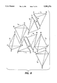
- FIGS. 7 and 8 illustrate how the color sample space of FIG. 6 can be partitioned into tetrahedrons
- FIG. 9 is a detailed block diagram of the FIG. 3 lookup table and the FIG. 3 interpolation circuit
- FIG. 10 is the process flow of the FIG. 9 interpolation circuit
- FIG. 11 shows step 67 of the FIG. 10 process flow in greater detail
- FIGS. 12 and 13 show step 68 of the FIG. 10 process flow in greater detail
- FIGS. 14 and 15 show step 68 of the FIG. 10 process flow in greater detail
- FIG. 16 is an example of a parallelepiped
- FIG. 17 is an example of a parallelepiped divided into tetrahedrons
- FIG. 18 is an example of a parallelepiped divided into prisms
- FIG. 19 is an example of parallelepipeds divided into more uniform tetrahedra than those shown in FIG. 17;
- FIG. 20 is an example of parallelepipeds divided into tetrahedra with body-centered sample points.
- FIG. 1 a basic system for carrying out the present invention is shown in FIG. 1.
- image input terminals IIT which include scanner 4, computer image creator 5 and image storage or file server 6 are connected to image processing unit (IPU) 8.
- IPU 8 is also connected to image output terminals (IOT) which include printer 10 and image display 11.
- Image information received by IPU 8 from an IIT is manipulated before being rendered by printer 10 or displayed on image display 11.
- IPU 8 can receive image information from auxiliary or remote IIT 12 and can transmit manipulated image information to auxiliary or remote IOT 14 using network 15.
- image signals or picture elements (pixels) representing image information transmitted from an IIT to IPU 8 have a resolution and pixel density.
- the image signals can represent color or black and white images, and can have a large number of density levels that are recorded in a gray level format.
- gray level is used herein to described data for both black and white and color images.
- Generally scanner 4 which may for example be the color scanner of the Xerox 5775 digital color copier, is calibrated to produce a set of digital signals to describe an original image using a colorimetric or device independent color space.
- generally computer image creator 5 consists of a workstation that executes a conventional graphical user application such as "GlobalView®” developed by the Xerox Corporation.
- the conventional graphical user application provides a high level, device independent graphics software environment for creating, editing and viewing high quality color electronic images using two dimensional image elements. More specifically, image elements forming an image emitted from computer image creator or page description language driver 5 are defined using high level primitives of a page description language (PDL) such as Interpress used by Xerox® Corporation.
- PDL page description language
- PDLs Postscript®
- HP-PCL Hewlett Packard Printer Control Language
- a PDL provides a set of commands that are used to describe various graphic and textual elements forming an image to be printed.
- Colorimetric spaces or models refer herein to color spaces which are transforms of CIE XYZ space (1931) (i.e. R,G,B color space) or the L*a*b* luminance-chrominance space (LC 1 C 2 ). While many color spaces have three dimensions, it is possible to have color spaces with less than three dimensions or more than three dimensions. Representing a color in a device independent manner between image input terminals and image output terminals using color models is well known. A number of color reference models or systems have been developed some of which are described in the Xerox Color Encoding Standard. It will be assumed herein that the additive RGB color model used to describe an image element on display 11 can be readily encoded using a known reference color model and converted to the CMY subtractive model. For example, the Xerox/RGBLinear color model described in the Xerox Color Encoding Standard can be used to represent the color of image elements developed on computer image creator 5.
- Resulting from the scanning of original image 20 is a set of scanner image signals R s , G s , B s , defined in device dependent scanner space, which is referred to herein as a color space which is defined only in terms of operation of a particular device using the color space.
- IPU 8 or scanner 4
- Post-scanning processor 22 provides correction of scanner image signals R s , G s , B s to colorimetric terms, R c , G c , B c , which are typically digital in nature.
- these device independent signals R c , G c , B c are in turn converted to device dependent signals using pre-printing processor 24.
- the output of pre-printing processor 24 is an image defined in terms of a device dependent space, or colorant driving signals C p , M p , Y p , K p that are used to drive printer 10.
- the colorant values, C,M,Y,K represent the relative amounts of cyan, magenta, yellow, and black toners that are to be deposited over a given area in an electrophotographic printer, such as, the Xerox 5775 digital color copier.
- a printed output image 26 can be defined in terms of R p , G p , B p , which is hoped to have a relationship with original image 20 which can be defined in terms of R o , G o , B o such that the printed output image 26 has a color that is colorimetrically similar to the original image, although that similarity is ultimately dependent upon the color gamut of the printing device.
- a scanned image described in colorimetric terms R c , G c , B c can be reproduced on display 11 using pre-display processor 28. It is well known how to model image signals to be displayed on a monitor and does not form part of the invention. Such displays contain three primary color phosphors. To generate a color defined by a set of R c , G c , B c values, the monitor stimulates each primary phosphor with an intensity determined by the corresponding R D , G D , B D value converted by pre-processor display 28. Also, images output by computer creator 5 and images retrieved from image storage 6 are generally specified in device independent colorimetric terms, R c , G c , B c using for example a PDL.
- the color of image signals or image elements may be represented in any of a variety of color notations or color spaces.
- an image can be rendered on printer 10 or displayed on display 11 independent of its originating image input terminal.
- pre-printing processor 24 which includes image color space transformation and color correction, initially, R c , G c , B c color signals are directed to an interpolation device 40, which includes a three dimensional lookup table stored in a device memory 42 such as a RAM or other addressable memory device, which will meet speed and memory requirements for a particular device.
- a device memory 42 such as a RAM or other addressable memory device
- Color signals R c , G c , B c are processed to generate address entries to the lookup table which stores a set of transform coefficients with which the R c , G c , B c may be processed to convert them to C x , M x , Y x , K x colorant signals or any multi-dimensional output color space including but not limited to CMYK or spectral data. Values which are not directly mapped from the table are determined in accordance with the present invention using tetrahedral interpolation over a hexagonal lattice, which is described in detail below.
- gray balance processing is performed at 46 to generate colorant driving signals C p , M p , Y p , K p , as described in U.S. Pat. No. 5,305,119 to Rolleston which is incorporated herein by reference.
- Colorant driving signals C p , M p , Y p , K p are then output to printer 10 for reproduction of the original scanner signals R s , G s , B s on printer 10 or IOT 14.
- a set of color patches are created, preferably including determined linearization and black addition. This is done by printing and measuring about 1000 to 4000 patches of printer colors distributed throughout the color space, i.e., a large set of printer driving signals are generated, in varying densities of combinations of C,M,Y,K, and used to drive the printer.
- the color of each patch is measured, using scanner 4 or a spectrophotometer 25 to determine color in terms of R c , G c , B c as shown in FIG. 2.
- the measured colors of these patches are used to build a three dimensional lookup table (LUT) relating R c , B c , G c defined colors to C x , M x , Y x , K x defined colors. Conversions that do not include mapped and measured points may be interpolated or extrapolated.
- LUT three dimensional lookup table
- a three dimensional lookup table can be generated by using a calibration image that is stored in a device memory such as calibration ROM 27.
- the calibration image which defines a set of CMYK input signals are directed from ROM 27 to printer 10 by controller 29.
- Densitometer or spectrophotometer 25 is used to scan calibration target 26 and produce R o G o B o signal values as a function of sensed density, representing the colors of each scanned patch.
- Interpatch correlation processor 31 reads the responses provided from densitometer 25 for each location in the calibration target and correlates the response with the input CMYK signals, to form a mapping which is inverted to yield an R c G c B c to CMYK mapping.
- LUT processor 32 receives data from interpatch correlation processor 31, and uses a linear interpolation function to generate additional data in the intervals between sampled data. LUT processor 32 may be responsive to operator or knowledge-based commands to generate more data in selected portions of the color gamut.
- FIG. 4 illustrates a two dimensional example of a conventional sample space used to derive an RGB to CMYK mapping lookup table.
- FIG. 5 is an illustration of a two dimensional sample space having a non-rectangular lattice (or non-rectangular sampling interval) which is used by LUT processor 32 in generating a lookup table.
- LUT processor 32 requires that every other row is shifted by a selected half a unit interval in one dimension to form a hexagonal lattice as shown in FIG. 5. This half unit shift of every other row adds an additional sample value to each shifted row.
- FIG. 6 shows the hexagonal lattice of FIG.
- sample points as shown in FIG. 6 define a color space that can be partitioned into tetrahedrons that have eight geometries T1-T8 which are shown in FIGS. 7 and 8. These eight geometries T1-T8 repeat throughout the sample space and are evaluated individually when correcting an image signal color space which is described in detail below.
- the lookup table mapping is stored in device memory 42 to form three dimensional lookup table (LUT) 50 shown in FIG. 9.
- Each memory address of the lookup table represents an image signal from a first color space (e.g. colorimetric values) that references a corresponding memory address location to provide corrective image signals in the second color space (e.g. printer signals).
- first color space e.g. colorimetric values
- second color space e.g. printer signals
- four address at 52 in LUT 50 refer to four points C, G, B and E which define a tetrahedron in the sample space shown in FIG. 6.
- the sample points can be stored in a uniform three-dimensional array or LUT. That only one of the dimensions (e.g. the x coordinate) is shifted, only one dimension requires an increased number of entries.
- a LUT size can be selected such that the index range is a power of two for two dimensions (e.g. 0 ⁇ x ⁇ 17, 0 ⁇ y ⁇ 16,0 ⁇ z ⁇ 16).
- This enables a LUT to be organized such that its indexing requires only simple masking and shifting operations. Consequently, LUT access does not require any multiplications and can be simple and efficiently implemented using conventional hardware or software.
- device independent signals R c , G c , B c are converted to device dependent signals or colorant driving signals C p , M p , Y p , K p using pre-printing processor 24.
- pre-printing processor 24 includes interpolation device 40 and a three dimensional lookup table which is stored in device memory 42. More specifically, FIG. 8 shows three dimensional LUT 50 which stores a set of transform coefficients with which the device independent signals R c , G c , B c are processed by interpolation device 40 to convert them to C x , M x , Y x , K x colorant signals.
- interpolation circuit 40 color correction is performed using interpolation circuit 40 and LUT 50.
- the process flow of interpolation circuit 40 is generally shown in FIG. 10.
- R c , G c , B c colorimetric signals are input to integer and fraction discriminator 54.
- discriminator 54 determines the integer component signals x i , y i , z i and fractional component signals x f , y f , z f , for an R c , G c , B c colorimetric signal.
- the integer and fractional component signals x i , y i , z i and x f , y f , z f are input to geometry inverter 55.
- geometry inverter 55 tests whether to use an even or an odd geometry, (shown in FIG. 6) by evaluating the relative position of the y and z integer components. If the geometry is odd, adjustments are made to each component of one dimension (e.g. ⁇ z ⁇ ) and an offset value ⁇ w ⁇ is set at step 65. If the geometry is even, the offset value ⁇ w ⁇ is set at step 66. Integer and fractional component signals are then input to tetrahedron selection circuit 57 and calculator circuit 58. Circuit 57 must first determine which tetrahedron geometry is appropriate before interpolation is performed using calculator circuit 58.
- tetrahedron selection circuit 57 selects a tetrahedron geometry from the set of eight possible tetrahedrons T1-T8 shown in FIGS. 7 and 8. Each tetrahedron T1-T8 has a unique characteristic equation.
- FIG. 10 shows step 67 which is performed by tetrahedron selection circuit 57 in detail. The selection process which is shown in FIG. 11, uses the fractional component signals x f , y f , z f to select from the set of eight tetrahedrons T1-T8. Specifically, circuit 57 tests each plane of the set of possible tetrahedra T1-T8 using the decision tree of FIG. 11.
- each parallelepiped cell shown in FIG. 6 is a unit cube.
- calculation circuit 58 evaluates an interpolation formula or a characteristic equation selected by indicator signal T n to provide corrected color signal C x , M x , Y x , K x .
- To evaluate the selected interpolation formula calculation circuit 58 interpolates over samples S(x, y, z) (where S is defined herein as C,M,Y and K such that S(x, y, z) corresponds to C(x, y, z), M(x, y, z), Y(x, y, z) and K(x, y, z)) taken at positions x, y, z in color space at step 68 which is shown in detail in FIGS. 12 and 13.
- Calculation circuit 58 therefore using integer and fractional component signals x i , y i , z i and x f , y f , z f , interpolates C x , M x , Y x , K x signals using color space samples from LUT 50.
- LUT address converter 59 adjusts positions of samples S(x, y, z) so that they correspond to entries P[a,b,c] in the color lookup table 50 (where P is defined herein as C,M,Y and K such that P[a,b,c] corresponds to C[a,b,c], M[a,b,c], Y[a,b,c] and K[a,b,c]).
- P is defined herein as C,M,Y and K such that P[a,b,c] corresponds to C[a,b,c], M[a,b,c], Y[a,b,c] and K[a,b,c]).
- Converter 59 adjusts samples S(x,y,z) according to the following expressions:
- Color lookup table 50 therefore consists of four tables with entries for each color separation C,M,Y,K.
- color lookup table 50 can consist of a table of vectors.
- Appendix is a C code listing of a software implementation for performing color correction by tetrahedral interpolation over a hexagonal lattice in accordance with the present invention.
- the implementation consists of determining the integer and fractional portions of the coordinates of a desired point. The determined integer and fractional portions are used for selection of the interpolating tetrahedron before actual interpolation. The implementation then determines whether to use even or odd geometry of FIG. 6. An odd geometry is accounted for by modifying the Z coordinate.
- each parallelepiped cell shown in FIG. 6 does not have to be a unit cube. What is required however by the invention is that a color sample space divided into parallelepipeds is not required to have all of its sample points or values at the vertex points of each parallelepiped. Accordingly, the present invention describes a method for color correction based on table look up and interpolation. The present invention differs from previous methods of tetrahedral interpolation in that sample points of color space for one of the dimensions are offset by half a unit on every other row, to form a hexagonal or triangular lattice of sample points.
- sample space geometry advantageously provides closer packing of sample points while still allowing easy table access and simple tests to determine which tetrahedron contains a desired point or value.
- the sample space geometry of the present invention defines uniform tetrahedrons while the closer packing of sample points in the space provides a dense sample space which reduces interpolation error without increasing the number of sample points required for interpolation.
- post-scanning processor 22 and pre-display processor 28 use a lookup table with interpolation to perform color correction and can therefore be readily modified to incorporate the present invention.
- the method of tetrahedral interpolation over a hexagonal lattice of the present invention is not limited to RGB and CMY color space and can be used to convert to any number of color spaces.
- the disclosed image processing system may be readily implemented in software using object oriented software development environments that provide portable source code that can be compiled for use on a variety of hardware platforms.
- the disclosed image processing system may be implemented partially or fully in hardware using standard logic circuits or specifically on a single chip using VLSI design. Whether software or hardware is used to implement the system varies depending on the speed and efficiency requirements of the system and also the particular function and the particular software or hardware systems and the particular microprocessor or microcomputer systems being utilized.
- the image processing system may be readily developed by those skilled in the applicable arts without undue experimentation from the functional description provided herein together with a general knowledge of the computer arts.
Abstract
Description
x=a-((b+c)mod 2)/2; y=b; and z=c.
Claims (21)
Priority Applications (1)
| Application Number | Priority Date | Filing Date | Title |
|---|---|---|---|
| US08/598,741 US5581376A (en) | 1994-08-29 | 1996-02-08 | System for correcting color images using tetrahedral interpolation over a hexagonal lattice |
Applications Claiming Priority (2)
| Application Number | Priority Date | Filing Date | Title |
|---|---|---|---|
| US29747394A | 1994-08-29 | 1994-08-29 | |
| US08/598,741 US5581376A (en) | 1994-08-29 | 1996-02-08 | System for correcting color images using tetrahedral interpolation over a hexagonal lattice |
Related Parent Applications (1)
| Application Number | Title | Priority Date | Filing Date |
|---|---|---|---|
| US29747394A Continuation | 1994-08-29 | 1994-08-29 |
Publications (1)
| Publication Number | Publication Date |
|---|---|
| US5581376A true US5581376A (en) | 1996-12-03 |
Family
ID=23146468
Family Applications (1)
| Application Number | Title | Priority Date | Filing Date |
|---|---|---|---|
| US08/598,741 Expired - Lifetime US5581376A (en) | 1994-08-29 | 1996-02-08 | System for correcting color images using tetrahedral interpolation over a hexagonal lattice |
Country Status (4)
| Country | Link |
|---|---|
| US (1) | US5581376A (en) |
| EP (1) | EP0700198B1 (en) |
| JP (1) | JPH0877341A (en) |
| DE (1) | DE69514596T2 (en) |
Cited By (121)
| Publication number | Priority date | Publication date | Assignee | Title |
|---|---|---|---|---|
| US5726780A (en) * | 1994-11-18 | 1998-03-10 | Minolta Co., Ltd. | Image processing apparatus |
| US5742350A (en) * | 1995-06-29 | 1998-04-21 | Motorola, Inc. | Video system performing non-uniform interpolation of color space signals and method of using same |
| US5748176A (en) * | 1995-07-20 | 1998-05-05 | Hewlett-Packard Company | Multi-variable colorimetric data access by iterative interpolation and subdivision |
| US5832109A (en) * | 1995-09-15 | 1998-11-03 | Agfa Gevaert N.V. | Method and apparatus for calculating color gamuts |
| EP0883290A2 (en) * | 1997-05-09 | 1998-12-09 | Kabushiki Kaisha Toshiba | Image processing apparatus and image forming apparatus |
| EP0896298A2 (en) * | 1997-06-12 | 1999-02-10 | Xerox Corporation | Ram address generation for tetrahaedrische Interpolation über einen hexagonalen Verbund |
| US5912657A (en) * | 1995-09-13 | 1999-06-15 | Yamaha Corporation | Image display device |
| US5917939A (en) * | 1993-09-29 | 1999-06-29 | Canon Kabushiki Kaisha | Image processing apparatus and image processing method |
| US5982990A (en) * | 1995-07-20 | 1999-11-09 | Hewlett-Packard Company | Method and apparatus for converting color space |
| US5991056A (en) * | 1995-09-29 | 1999-11-23 | Fuji Photo Film Co., Ltd. | Image processing apparatus for performing tonal and color matrix transformations |
| US6009192A (en) * | 1996-12-19 | 1999-12-28 | Xerox Corporation | Color correction of a compressed image |
| US6075886A (en) * | 1998-03-09 | 2000-06-13 | Xerox Corporation | Method and apparatus for reducing the complexity of color correction using subsampling |
| US6081253A (en) * | 1998-02-10 | 2000-06-27 | Bronson Color Company, Inc. | Method for generating numerous harmonious color palettes from two colors |
| US6147672A (en) * | 1995-04-07 | 2000-11-14 | Kabushiki Kaisha Toshiba | Display signal interface system between display controller and display apparatus |
| US6160644A (en) * | 1998-03-30 | 2000-12-12 | Seiko Epson Corporation | Scanner calibration technique to overcome tone inversion |
| US6178007B1 (en) | 1997-01-21 | 2001-01-23 | Xerox Corporation | Method for continuous incremental color calibration for color document output terminals |
| US6181445B1 (en) | 1998-03-30 | 2001-01-30 | Seiko Epson Corporation | Device-independent and medium-independent color matching between an input device and an output device |
| US6185004B1 (en) | 1998-03-30 | 2001-02-06 | Seiko Epson Corporation | Self-calibration for color image reproduction system |
| US6204939B1 (en) | 1998-03-30 | 2001-03-20 | Seiko Epson Corporation | Color matching accuracy inside and outside the gamut |
| US6222648B1 (en) * | 1997-01-21 | 2001-04-24 | Xerox Corporation | On line compensation for slow drift of color fidelity in document output terminals (DOT) |
| US6239886B1 (en) | 1998-01-08 | 2001-05-29 | Xerox Corporation | Method and apparatus for correcting luminance and chrominance data in digital color images |
| US6268867B1 (en) * | 1996-10-29 | 2001-07-31 | Mitsubishi Denki Kabushiki Kaisha | Method and apparatus for color correction and apparatus for applying color correction |
| US6268939B1 (en) | 1998-01-08 | 2001-07-31 | Xerox Corporation | Method and apparatus for correcting luminance and chrominance data in digital color images |
| US6295137B1 (en) | 1998-12-11 | 2001-09-25 | Xerox Corporation | Method of color correction using multi-level halftoning |
| US6304671B1 (en) * | 1997-10-08 | 2001-10-16 | Seiko Epson Corporation | Image processing apparatus using an offset correction table enabling interpolation to be performed without conditional jumps |
| US6320668B1 (en) * | 1997-07-10 | 2001-11-20 | Samsung Electronics Co., Ltd. | Color correction apparatus and method in an image system |
| US6330078B1 (en) | 1998-12-09 | 2001-12-11 | Xerox Corporation | Feedback method and apparatus for printing calibration |
| US20020021458A1 (en) * | 2000-07-14 | 2002-02-21 | Kazuhiro Saito | Image processing method, image processing apparatus, and programs thereof |
| US6360007B1 (en) | 1998-12-22 | 2002-03-19 | Xerox Corporation | Dynamic optimized color lut transformations based upon image requirements |
| US6373580B1 (en) * | 1998-06-23 | 2002-04-16 | Eastman Kodak Company | Method and apparatus for multi-dimensional interpolation |
| US20020044150A1 (en) * | 1998-10-08 | 2002-04-18 | Mitsubishi Denki Kabushiki Kaisha | Color characteristic description apparatus, color management apparatus, image conversion apparatus and color correction method |
| US6380539B1 (en) | 1997-01-30 | 2002-04-30 | Applied Science Fiction, Inc. | Four color trilinear CCD scanning |
| US6393160B1 (en) | 1998-03-13 | 2002-05-21 | Applied Science Fiction | Image defect correction in transform space |
| US6404516B1 (en) | 1999-02-22 | 2002-06-11 | Applied Science Fiction, Inc. | Parametric image stitching |
| US6404511B1 (en) | 1998-12-11 | 2002-06-11 | Seiko Epson Corporation | Self-calibration of network copier system |
| US20020101456A1 (en) * | 2001-01-29 | 2002-08-01 | Hirochika Matsuoka | Color-information processing method, and program |
| US20020106134A1 (en) * | 2000-09-22 | 2002-08-08 | Dundon Thomas A. | Multiple-orientation image defect detection and correction |
| US6437358B1 (en) | 1999-02-04 | 2002-08-20 | Applied Science Fiction, Inc. | Apparatus and methods for capturing defect data |
| US20020113982A1 (en) * | 2000-12-19 | 2002-08-22 | Sharp Laboratories Of America, Inc. | Black generation method for CMYK color printer using multiple lookup tables and interpolation |
| US6442301B1 (en) | 1997-01-06 | 2002-08-27 | Applied Science Fiction, Inc. | Apparatus and method for defect channel nulling |
| US6439784B1 (en) | 1999-08-17 | 2002-08-27 | Applied Science Fiction, Inc. | Method and system for using calibration patches in electronic film processing |
| US6443639B1 (en) | 1999-06-29 | 2002-09-03 | Applied Science Fiction, Inc. | Slot coater device for applying developer to film for electronic film development |
| US20020122207A1 (en) * | 2000-12-28 | 2002-09-05 | Xerox Corporation | Fast Interpolation of large color lookup tables |
| US6447178B2 (en) | 1999-12-30 | 2002-09-10 | Applied Science Fiction, Inc. | System, method, and apparatus for providing multiple extrusion widths |
| US6461061B2 (en) | 1999-12-30 | 2002-10-08 | Applied Science Fiction, Inc. | System and method for digital film development using visible light |
| US6466333B2 (en) * | 1998-06-26 | 2002-10-15 | Canon Kabushiki Kaisha | Streamlined tetrahedral interpolation |
| US20020159165A1 (en) * | 2000-09-22 | 2002-10-31 | Ford Gordon D. | Lens focusing device, system and method for use with multiple light wavelengths |
| US6475711B1 (en) | 1999-12-31 | 2002-11-05 | Applied Science Fiction, Inc. | Photographic element and digital film processing method using same |
| US6487321B1 (en) | 1999-09-16 | 2002-11-26 | Applied Science Fiction | Method and system for altering defects in a digital image |
| US6498867B1 (en) | 1999-10-08 | 2002-12-24 | Applied Science Fiction Inc. | Method and apparatus for differential illumination image-capturing and defect handling |
| US6503002B1 (en) | 1996-12-05 | 2003-01-07 | Applied Science Fiction, Inc. | Method and apparatus for reducing noise in electronic film development |
| US6505977B2 (en) | 1999-12-30 | 2003-01-14 | Applied Science Fiction, Inc. | System and method for digital color dye film processing |
| US20030011827A1 (en) * | 1999-12-29 | 2003-01-16 | Applied Science Fiction | Distinguishing positive and negative films system and method |
| US6512601B1 (en) | 1998-02-23 | 2003-01-28 | Applied Science Fiction, Inc. | Progressive area scan in electronic film development |
| US6512841B2 (en) * | 1997-08-29 | 2003-01-28 | Fuji Photo Film Co., Ltd. | Image processing system |
| US6540416B2 (en) | 1999-12-30 | 2003-04-01 | Applied Science Fiction, Inc. | System and method for digital film development using visible light |
| US6554504B2 (en) | 1999-12-30 | 2003-04-29 | Applied Science Fiction, Inc. | Distributed digital film processing system and method |
| US6558052B2 (en) | 1997-01-30 | 2003-05-06 | Applied Science Fiction, Inc. | System and method for latent film recovery in electronic film development |
| US20030117415A1 (en) * | 2001-12-11 | 2003-06-26 | Stmicroelectronics, Inc. | Color transformation in 3D color space |
| US20030118249A1 (en) * | 2001-04-19 | 2003-06-26 | Edgar Albert D. | Method, system and software for correcting image defects |
| US6590679B1 (en) | 1998-02-04 | 2003-07-08 | Applied Science Fiction, Inc. | Multilinear array sensor with an infrared line |
| US6593558B1 (en) | 1996-05-10 | 2003-07-15 | Applied Science Fiction, Inc. | Luminance-priority electronic color image sensor |
| US6594041B1 (en) | 1998-11-20 | 2003-07-15 | Applied Science Fiction, Inc. | Log time processing and stitching system |
| US6599036B2 (en) | 2000-02-03 | 2003-07-29 | Applied Science Fiction, Inc. | Film processing solution cartridge and method for developing and digitizing film |
| US6614946B1 (en) | 1999-10-08 | 2003-09-02 | Eastman Kodak Company | System and method for correcting defects in digital images through selective fill-in from surrounding areas |
| US20030169438A1 (en) * | 2001-11-26 | 2003-09-11 | Velde Koen Vande | Colour separation method |
| US6619863B2 (en) | 2000-02-03 | 2003-09-16 | Eastman Kodak Company | Method and system for capturing film images |
| US6625306B1 (en) | 1999-12-07 | 2003-09-23 | Xerox Corporation | Color gamut mapping for accurately mapping certain critical colors and corresponding transforming of nearby colors and enhancing global smoothness |
| US20030193678A1 (en) * | 2002-04-15 | 2003-10-16 | Yao Han | Method of calibrating a scanner to a printer |
| US6650336B2 (en) * | 2000-05-17 | 2003-11-18 | Minolta Co., Ltd. | Color conversion device and method capable of improving color reproduction |
| US6664034B2 (en) | 1999-12-31 | 2003-12-16 | Eastman Kodak Company | Digital film processing method |
| US6683995B2 (en) | 1999-12-23 | 2004-01-27 | Eastman Kodak Company | Method and apparatus for correcting large defects in digital images |
| US6704458B2 (en) | 1999-12-29 | 2004-03-09 | Eastman Kodak Company | Method and apparatus for correcting heavily damaged images |
| US6707557B2 (en) | 1999-12-30 | 2004-03-16 | Eastman Kodak Company | Method and system for estimating sensor dark current drift and sensor/illumination non-uniformities |
| US6711302B1 (en) | 1999-10-20 | 2004-03-23 | Eastman Kodak Company | Method and system for altering defects in digital image |
| US6714319B1 (en) | 1999-12-03 | 2004-03-30 | Xerox Corporation | On-line piecewise homeomorphism model prediction, control and calibration system for a dynamically varying color marking device |
| US6720560B1 (en) | 1999-12-30 | 2004-04-13 | Eastman Kodak Company | Method and apparatus for scanning images |
| US6733960B2 (en) | 2001-02-09 | 2004-05-11 | Eastman Kodak Company | Digital film processing solutions and method of digital film processing |
| US20040114047A1 (en) * | 2002-12-13 | 2004-06-17 | Vora Poorvi L. | Method for transforming an offset sensor array |
| US6771275B1 (en) * | 2000-06-07 | 2004-08-03 | Oak Technology, Inc. | Processing system and method using a multi-dimensional look-up table |
| US6781620B1 (en) | 1999-03-16 | 2004-08-24 | Eastman Kodak Company | Mixed-element stitching and noise reduction system |
| US6786655B2 (en) | 2000-02-03 | 2004-09-07 | Eastman Kodak Company | Method and system for self-service film processing |
| US6788335B2 (en) | 1999-12-30 | 2004-09-07 | Eastman Kodak Company | Pulsed illumination signal modulation control & adjustment method and system |
| US6805501B2 (en) | 2001-07-16 | 2004-10-19 | Eastman Kodak Company | System and method for digital film development using visible light |
| US20040207879A1 (en) * | 2003-04-16 | 2004-10-21 | Bailey James Ray | Systems and methods for error diffusion |
| US6809837B1 (en) | 1999-11-29 | 2004-10-26 | Xerox Corporation | On-line model prediction and calibration system for a dynamically varying color reproduction device |
| US6813392B2 (en) | 1999-12-30 | 2004-11-02 | Eastman Kodak Company | Method and apparatus for aligning multiple scans of the same area of a medium using mathematical correlation |
| US20050027912A1 (en) * | 2000-05-11 | 2005-02-03 | Sony Corporation | Data processing apparatus, data processing method, and recording medium therefor |
| US6862110B2 (en) | 2000-12-18 | 2005-03-01 | Xerox Corporation | Method and apparatus for controlling page cost in an image-rendering device |
| US6862117B1 (en) | 1999-12-30 | 2005-03-01 | Eastman Kodak Company | Method and apparatus for reducing the effect of bleed-through on captured images |
| US6864973B2 (en) | 1999-12-30 | 2005-03-08 | Eastman Kodak Company | Method and apparatus to pre-scan and pre-treat film for improved digital film processing handling |
| US20050052466A1 (en) * | 2003-09-06 | 2005-03-10 | Match Lab, Inc. | Color conversion method and apparatus |
| US6867883B1 (en) | 2000-01-21 | 2005-03-15 | Lexmark International, Inc. | Method and apparatus for expanding a color gamut |
| US6873432B1 (en) | 1999-11-30 | 2005-03-29 | Xerox Corporation | Method and apparatus for representing color space transformations with a piecewise homeomorphism |
| US6888997B2 (en) | 2000-12-05 | 2005-05-03 | Eastman Kodak Company | Waveguide device and optical transfer system for directing light to an image plane |
| US6915021B2 (en) | 1999-12-17 | 2005-07-05 | Eastman Kodak Company | Method and system for selective enhancement of image data |
| US6924911B1 (en) | 1999-10-12 | 2005-08-02 | Eastman Kodak Company | Method and system for multi-sensor signal detection |
| US6943920B2 (en) | 2000-02-03 | 2005-09-13 | Eastman Kodak Company | Method, system, and software for signal processing using pyramidal decomposition |
| US6965692B1 (en) | 1999-12-30 | 2005-11-15 | Eastman Kodak Company | Method and apparatus for improving the quality of reconstructed information |
| US6967742B1 (en) * | 1997-11-28 | 2005-11-22 | Canon Kabushiki Kaisha | Printer server, method for processing data and storage medium |
| US20050276472A1 (en) * | 2002-03-27 | 2005-12-15 | Microsoft Corporation | System and method for progressively transforming and coding digital data |
| US20050285871A1 (en) * | 2004-06-29 | 2005-12-29 | Canon Kabushiki Kaisha | Image-processing circuit, electronic apparatus, and method for processing image |
| US6990251B2 (en) | 2000-02-03 | 2006-01-24 | Eastman Kodak Company | Method, system, and software for signal processing using sheep and shepherd artifacts |
| US20060041609A1 (en) * | 2004-08-20 | 2006-02-23 | Pellar Ronald J | System and method for multi-dimensional lookup table interpolation |
| US7016080B2 (en) | 2000-09-21 | 2006-03-21 | Eastman Kodak Company | Method and system for improving scanned image detail |
| US7020344B2 (en) | 2000-02-03 | 2006-03-28 | Eastman Kodak Company | Match blur system and method |
| US20070052720A1 (en) * | 2005-06-30 | 2007-03-08 | Shashikiran Tadas | Method, apparatus and system for performing tetrahedral color conversion for image processing |
| US20070115338A1 (en) * | 2005-11-22 | 2007-05-24 | Xerox Corporation | Streak compensation with scan line dependent ROS actuation |
| US7263240B2 (en) | 2002-01-14 | 2007-08-28 | Eastman Kodak Company | Method, system, and software for improving signal quality using pyramidal decomposition |
| US20070247648A1 (en) * | 2006-04-25 | 2007-10-25 | Xerox Corporation | Method for tetrahedral interpolation computations using data-level parallelism |
| US20070252848A1 (en) * | 2006-04-27 | 2007-11-01 | Kabushiki Kaisha Toshiba | Color conversion apparatus and color conversion method |
| US7397483B1 (en) * | 1998-07-02 | 2008-07-08 | Canon Kabushiki Kaisha | Image data conversion using interpolation |
| US20090066978A1 (en) * | 2007-09-11 | 2009-03-12 | Xerox Corporation | Method and system for improved space filling interpolation |
| US8098260B1 (en) * | 2007-05-31 | 2012-01-17 | Zoran Corporation | Method and apparatus for mapping a multi-dimensional signal from one space to another space |
| CN102393965A (en) * | 2011-06-01 | 2012-03-28 | 博雅智汇国际有限公司 | Method for correcting colour of colour difference meter by utilizing tetrahedron interpolation method |
| US20120147378A1 (en) * | 2006-09-08 | 2012-06-14 | Dai Nippon Printing Co., Ltd. | Evaluation method of fouling, fouling evaluation apparatus, production method of optical member, optical layered body, and display product |
| US20130100157A1 (en) * | 2011-10-21 | 2013-04-25 | Peter Morovic | Method and system to modify a color lookup table |
| US20140161350A1 (en) * | 2012-12-11 | 2014-06-12 | Novatek Microelectronics Corp. | Color translation method and color translation apparatus |
| US10244148B2 (en) * | 2016-06-03 | 2019-03-26 | Konica Minolta, Inc. | Printer, color conversion control program and color conversion control method |
| US10356282B2 (en) * | 2016-05-06 | 2019-07-16 | Canon Kabushiki Kaisha | Image processing apparatus and color separation processing method by interpolation processing using a multi-dimensional lookup table |
| US10582089B2 (en) | 2017-11-16 | 2020-03-03 | Apical Limited | Image data interpolation |
Families Citing this family (6)
| Publication number | Priority date | Publication date | Assignee | Title |
|---|---|---|---|---|
| AU2889597A (en) * | 1996-05-03 | 1997-11-26 | Harlequin Group Plc | System and method for processing a page description in an imaging system |
| GB2318943A (en) * | 1996-10-31 | 1998-05-06 | Hewlett Packard Co | Image colour conversion |
| US7304769B2 (en) * | 2003-05-30 | 2007-12-04 | Hewlett-Packard Development Company, L.P. | Color imaging devices, color image forming methods, and color image data processing methods |
| US7295215B2 (en) | 2004-08-20 | 2007-11-13 | Xerox Corporation | Method for calculating colorant error from reflectance measurement |
| EP1903775B1 (en) * | 2006-09-21 | 2010-06-16 | Thomson Licensing | Method for conversion of a colour space using separate chromatic and luminance look-up tables |
| JP2010056794A (en) * | 2008-08-27 | 2010-03-11 | Canon Inc | Chart for multi-color calibration, and image processing method and image processing apparatus using the chart |
Citations (8)
| Publication number | Priority date | Publication date | Assignee | Title |
|---|---|---|---|---|
| US2790844A (en) * | 1954-05-11 | 1957-04-30 | Adalia Ltd | Color correction selector |
| US4275413A (en) * | 1978-03-30 | 1981-06-23 | Takashi Sakamoto | Linear interpolator for color correction |
| US4477833A (en) * | 1981-08-12 | 1984-10-16 | R. R. Donnelley & Sons Company | Method of color conversion with improved interpolation |
| US4500919A (en) * | 1982-05-04 | 1985-02-19 | Massachusetts Institute Of Technology | Color reproduction system |
| US5241373A (en) * | 1990-05-16 | 1993-08-31 | Matsushita Electric Industrial Co., Ltd. | Apparatus for correction of color signal values |
| US5305119A (en) * | 1992-10-01 | 1994-04-19 | Xerox Corporation | Color printer calibration architecture |
| US5377041A (en) * | 1993-10-27 | 1994-12-27 | Eastman Kodak Company | Method and apparatus employing mean preserving spatial modulation for transforming a digital color image signal |
| US5390035A (en) * | 1992-12-23 | 1995-02-14 | International Business Machines Corporation | Method and means for tetrahedron/octahedron packing and tetrahedron extraction for function approximation |
Family Cites Families (1)
| Publication number | Priority date | Publication date | Assignee | Title |
|---|---|---|---|---|
| JP2895086B2 (en) * | 1989-02-28 | 1999-05-24 | コニカ株式会社 | Color estimation method |
-
1995
- 1995-08-21 JP JP7211527A patent/JPH0877341A/en active Pending
- 1995-08-24 DE DE69514596T patent/DE69514596T2/en not_active Expired - Fee Related
- 1995-08-24 EP EP95305945A patent/EP0700198B1/en not_active Expired - Lifetime
-
1996
- 1996-02-08 US US08/598,741 patent/US5581376A/en not_active Expired - Lifetime
Patent Citations (8)
| Publication number | Priority date | Publication date | Assignee | Title |
|---|---|---|---|---|
| US2790844A (en) * | 1954-05-11 | 1957-04-30 | Adalia Ltd | Color correction selector |
| US4275413A (en) * | 1978-03-30 | 1981-06-23 | Takashi Sakamoto | Linear interpolator for color correction |
| US4477833A (en) * | 1981-08-12 | 1984-10-16 | R. R. Donnelley & Sons Company | Method of color conversion with improved interpolation |
| US4500919A (en) * | 1982-05-04 | 1985-02-19 | Massachusetts Institute Of Technology | Color reproduction system |
| US5241373A (en) * | 1990-05-16 | 1993-08-31 | Matsushita Electric Industrial Co., Ltd. | Apparatus for correction of color signal values |
| US5305119A (en) * | 1992-10-01 | 1994-04-19 | Xerox Corporation | Color printer calibration architecture |
| US5390035A (en) * | 1992-12-23 | 1995-02-14 | International Business Machines Corporation | Method and means for tetrahedron/octahedron packing and tetrahedron extraction for function approximation |
| US5377041A (en) * | 1993-10-27 | 1994-12-27 | Eastman Kodak Company | Method and apparatus employing mean preserving spatial modulation for transforming a digital color image signal |
Non-Patent Citations (6)
| Title |
|---|
| A Color Transformation Algorithm Using "Prism" Interpolation Kanamori, IS & TS Eight Intern'l Congress on Advances in Non-Impact Prinoting Technologies, (1992) pp. 477-482. |
| A Color Transformation Algorithm Using Prism Interpolation Kanamori, IS & TS Eight Intern l Congress on Advances in Non Impact Prinoting Technologies, (1992) pp. 477 482. * |
| Color Correction Technique for Hard Copies by 4 Neighbors Interpolation Method, Kanamori Journal of Imaging Science and Technology vol. 36, No. 1 Jan./Feb. 1992 pp. 73 80. * |
| Color Correction Technique for Hard Copies by 4-Neighbors Interpolation Method, Kanamori Journal of Imaging Science and Technology vol. 36, No. 1 Jan./Feb. 1992 pp. 73-80. |
| Research Report "Tetrahedral Interpolation Technique for Color Space Conversion" James Kasson Jan. 1993 IBM Research Division. |
| Research Report Tetrahedral Interpolation Technique for Color Space Conversion James Kasson Jan. 1993 IBM Research Division. * |
Cited By (162)
| Publication number | Priority date | Publication date | Assignee | Title |
|---|---|---|---|---|
| US5917939A (en) * | 1993-09-29 | 1999-06-29 | Canon Kabushiki Kaisha | Image processing apparatus and image processing method |
| US5726780A (en) * | 1994-11-18 | 1998-03-10 | Minolta Co., Ltd. | Image processing apparatus |
| US6147672A (en) * | 1995-04-07 | 2000-11-14 | Kabushiki Kaisha Toshiba | Display signal interface system between display controller and display apparatus |
| US5742350A (en) * | 1995-06-29 | 1998-04-21 | Motorola, Inc. | Video system performing non-uniform interpolation of color space signals and method of using same |
| US5748176A (en) * | 1995-07-20 | 1998-05-05 | Hewlett-Packard Company | Multi-variable colorimetric data access by iterative interpolation and subdivision |
| US5982990A (en) * | 1995-07-20 | 1999-11-09 | Hewlett-Packard Company | Method and apparatus for converting color space |
| US5912657A (en) * | 1995-09-13 | 1999-06-15 | Yamaha Corporation | Image display device |
| US5832109A (en) * | 1995-09-15 | 1998-11-03 | Agfa Gevaert N.V. | Method and apparatus for calculating color gamuts |
| US5991056A (en) * | 1995-09-29 | 1999-11-23 | Fuji Photo Film Co., Ltd. | Image processing apparatus for performing tonal and color matrix transformations |
| US6593558B1 (en) | 1996-05-10 | 2003-07-15 | Applied Science Fiction, Inc. | Luminance-priority electronic color image sensor |
| US6268867B1 (en) * | 1996-10-29 | 2001-07-31 | Mitsubishi Denki Kabushiki Kaisha | Method and apparatus for color correction and apparatus for applying color correction |
| US6503002B1 (en) | 1996-12-05 | 2003-01-07 | Applied Science Fiction, Inc. | Method and apparatus for reducing noise in electronic film development |
| US6009192A (en) * | 1996-12-19 | 1999-12-28 | Xerox Corporation | Color correction of a compressed image |
| US6442301B1 (en) | 1997-01-06 | 2002-08-27 | Applied Science Fiction, Inc. | Apparatus and method for defect channel nulling |
| US6222648B1 (en) * | 1997-01-21 | 2001-04-24 | Xerox Corporation | On line compensation for slow drift of color fidelity in document output terminals (DOT) |
| US6178007B1 (en) | 1997-01-21 | 2001-01-23 | Xerox Corporation | Method for continuous incremental color calibration for color document output terminals |
| US6558052B2 (en) | 1997-01-30 | 2003-05-06 | Applied Science Fiction, Inc. | System and method for latent film recovery in electronic film development |
| US6380539B1 (en) | 1997-01-30 | 2002-04-30 | Applied Science Fiction, Inc. | Four color trilinear CCD scanning |
| EP0883290A3 (en) * | 1997-05-09 | 1999-11-03 | Kabushiki Kaisha Toshiba | Image processing apparatus and image forming apparatus |
| EP0883290A2 (en) * | 1997-05-09 | 1998-12-09 | Kabushiki Kaisha Toshiba | Image processing apparatus and image forming apparatus |
| US6269185B1 (en) | 1997-05-09 | 2001-07-31 | Kabushiki Kaisha Toshiba | Image processing apparatus and image forming apparatus |
| EP0896298A2 (en) * | 1997-06-12 | 1999-02-10 | Xerox Corporation | Ram address generation for tetrahaedrische Interpolation über einen hexagonalen Verbund |
| EP0896298A3 (en) * | 1997-06-12 | 1999-11-17 | Xerox Corporation | Ram address generation for tetrahedral interpolation |
| US6320668B1 (en) * | 1997-07-10 | 2001-11-20 | Samsung Electronics Co., Ltd. | Color correction apparatus and method in an image system |
| US6512841B2 (en) * | 1997-08-29 | 2003-01-28 | Fuji Photo Film Co., Ltd. | Image processing system |
| US6304671B1 (en) * | 1997-10-08 | 2001-10-16 | Seiko Epson Corporation | Image processing apparatus using an offset correction table enabling interpolation to be performed without conditional jumps |
| US6967742B1 (en) * | 1997-11-28 | 2005-11-22 | Canon Kabushiki Kaisha | Printer server, method for processing data and storage medium |
| US6239886B1 (en) | 1998-01-08 | 2001-05-29 | Xerox Corporation | Method and apparatus for correcting luminance and chrominance data in digital color images |
| US6268939B1 (en) | 1998-01-08 | 2001-07-31 | Xerox Corporation | Method and apparatus for correcting luminance and chrominance data in digital color images |
| US6590679B1 (en) | 1998-02-04 | 2003-07-08 | Applied Science Fiction, Inc. | Multilinear array sensor with an infrared line |
| US6081253A (en) * | 1998-02-10 | 2000-06-27 | Bronson Color Company, Inc. | Method for generating numerous harmonious color palettes from two colors |
| US6512601B1 (en) | 1998-02-23 | 2003-01-28 | Applied Science Fiction, Inc. | Progressive area scan in electronic film development |
| US6075886A (en) * | 1998-03-09 | 2000-06-13 | Xerox Corporation | Method and apparatus for reducing the complexity of color correction using subsampling |
| US6393160B1 (en) | 1998-03-13 | 2002-05-21 | Applied Science Fiction | Image defect correction in transform space |
| US6160644A (en) * | 1998-03-30 | 2000-12-12 | Seiko Epson Corporation | Scanner calibration technique to overcome tone inversion |
| US6181445B1 (en) | 1998-03-30 | 2001-01-30 | Seiko Epson Corporation | Device-independent and medium-independent color matching between an input device and an output device |
| US6421142B1 (en) | 1998-03-30 | 2002-07-16 | Seiko Epson Corporation | Out-of-gamut color mapping strategy |
| US6204939B1 (en) | 1998-03-30 | 2001-03-20 | Seiko Epson Corporation | Color matching accuracy inside and outside the gamut |
| US6185004B1 (en) | 1998-03-30 | 2001-02-06 | Seiko Epson Corporation | Self-calibration for color image reproduction system |
| US6373580B1 (en) * | 1998-06-23 | 2002-04-16 | Eastman Kodak Company | Method and apparatus for multi-dimensional interpolation |
| US6466333B2 (en) * | 1998-06-26 | 2002-10-15 | Canon Kabushiki Kaisha | Streamlined tetrahedral interpolation |
| US7397483B1 (en) * | 1998-07-02 | 2008-07-08 | Canon Kabushiki Kaisha | Image data conversion using interpolation |
| US7414633B2 (en) * | 1998-10-08 | 2008-08-19 | Mitsubishi Denki Kabushiki Kaisha | Color characteristics description apparatus, color management apparatus, image conversion apparatus and color correction method |
| US20020044150A1 (en) * | 1998-10-08 | 2002-04-18 | Mitsubishi Denki Kabushiki Kaisha | Color characteristic description apparatus, color management apparatus, image conversion apparatus and color correction method |
| US6594041B1 (en) | 1998-11-20 | 2003-07-15 | Applied Science Fiction, Inc. | Log time processing and stitching system |
| US6330078B1 (en) | 1998-12-09 | 2001-12-11 | Xerox Corporation | Feedback method and apparatus for printing calibration |
| US6295137B1 (en) | 1998-12-11 | 2001-09-25 | Xerox Corporation | Method of color correction using multi-level halftoning |
| US6404511B1 (en) | 1998-12-11 | 2002-06-11 | Seiko Epson Corporation | Self-calibration of network copier system |
| US6360007B1 (en) | 1998-12-22 | 2002-03-19 | Xerox Corporation | Dynamic optimized color lut transformations based upon image requirements |
| US6437358B1 (en) | 1999-02-04 | 2002-08-20 | Applied Science Fiction, Inc. | Apparatus and methods for capturing defect data |
| US6404516B1 (en) | 1999-02-22 | 2002-06-11 | Applied Science Fiction, Inc. | Parametric image stitching |
| US6781620B1 (en) | 1999-03-16 | 2004-08-24 | Eastman Kodak Company | Mixed-element stitching and noise reduction system |
| US6443639B1 (en) | 1999-06-29 | 2002-09-03 | Applied Science Fiction, Inc. | Slot coater device for applying developer to film for electronic film development |
| US6439784B1 (en) | 1999-08-17 | 2002-08-27 | Applied Science Fiction, Inc. | Method and system for using calibration patches in electronic film processing |
| US6487321B1 (en) | 1999-09-16 | 2002-11-26 | Applied Science Fiction | Method and system for altering defects in a digital image |
| US6650789B2 (en) | 1999-09-16 | 2003-11-18 | Eastman Kodak Company | Method and system for altering defects in a digital image |
| US6498867B1 (en) | 1999-10-08 | 2002-12-24 | Applied Science Fiction Inc. | Method and apparatus for differential illumination image-capturing and defect handling |
| US6614946B1 (en) | 1999-10-08 | 2003-09-02 | Eastman Kodak Company | System and method for correcting defects in digital images through selective fill-in from surrounding areas |
| US6924911B1 (en) | 1999-10-12 | 2005-08-02 | Eastman Kodak Company | Method and system for multi-sensor signal detection |
| US6711302B1 (en) | 1999-10-20 | 2004-03-23 | Eastman Kodak Company | Method and system for altering defects in digital image |
| US6809837B1 (en) | 1999-11-29 | 2004-10-26 | Xerox Corporation | On-line model prediction and calibration system for a dynamically varying color reproduction device |
| US6873432B1 (en) | 1999-11-30 | 2005-03-29 | Xerox Corporation | Method and apparatus for representing color space transformations with a piecewise homeomorphism |
| US6714319B1 (en) | 1999-12-03 | 2004-03-30 | Xerox Corporation | On-line piecewise homeomorphism model prediction, control and calibration system for a dynamically varying color marking device |
| US6625306B1 (en) | 1999-12-07 | 2003-09-23 | Xerox Corporation | Color gamut mapping for accurately mapping certain critical colors and corresponding transforming of nearby colors and enhancing global smoothness |
| US6915021B2 (en) | 1999-12-17 | 2005-07-05 | Eastman Kodak Company | Method and system for selective enhancement of image data |
| US6683995B2 (en) | 1999-12-23 | 2004-01-27 | Eastman Kodak Company | Method and apparatus for correcting large defects in digital images |
| US20030011827A1 (en) * | 1999-12-29 | 2003-01-16 | Applied Science Fiction | Distinguishing positive and negative films system and method |
| US6704458B2 (en) | 1999-12-29 | 2004-03-09 | Eastman Kodak Company | Method and apparatus for correcting heavily damaged images |
| US7164511B2 (en) | 1999-12-29 | 2007-01-16 | Eastman Kodak Company | Distinguishing positive and negative films system and method |
| US6447178B2 (en) | 1999-12-30 | 2002-09-10 | Applied Science Fiction, Inc. | System, method, and apparatus for providing multiple extrusion widths |
| US6720560B1 (en) | 1999-12-30 | 2004-04-13 | Eastman Kodak Company | Method and apparatus for scanning images |
| US6813392B2 (en) | 1999-12-30 | 2004-11-02 | Eastman Kodak Company | Method and apparatus for aligning multiple scans of the same area of a medium using mathematical correlation |
| US6862117B1 (en) | 1999-12-30 | 2005-03-01 | Eastman Kodak Company | Method and apparatus for reducing the effect of bleed-through on captured images |
| US6965692B1 (en) | 1999-12-30 | 2005-11-15 | Eastman Kodak Company | Method and apparatus for improving the quality of reconstructed information |
| US6554504B2 (en) | 1999-12-30 | 2003-04-29 | Applied Science Fiction, Inc. | Distributed digital film processing system and method |
| US6864973B2 (en) | 1999-12-30 | 2005-03-08 | Eastman Kodak Company | Method and apparatus to pre-scan and pre-treat film for improved digital film processing handling |
| US6540416B2 (en) | 1999-12-30 | 2003-04-01 | Applied Science Fiction, Inc. | System and method for digital film development using visible light |
| US6505977B2 (en) | 1999-12-30 | 2003-01-14 | Applied Science Fiction, Inc. | System and method for digital color dye film processing |
| US6705777B2 (en) | 1999-12-30 | 2004-03-16 | Eastman Kodak Company | System and method for digital film development using visible light |
| US6707557B2 (en) | 1999-12-30 | 2004-03-16 | Eastman Kodak Company | Method and system for estimating sensor dark current drift and sensor/illumination non-uniformities |
| US6793417B2 (en) | 1999-12-30 | 2004-09-21 | Eastman Kodak Company | System and method for digital film development using visible light |
| US6788335B2 (en) | 1999-12-30 | 2004-09-07 | Eastman Kodak Company | Pulsed illumination signal modulation control & adjustment method and system |
| US6461061B2 (en) | 1999-12-30 | 2002-10-08 | Applied Science Fiction, Inc. | System and method for digital film development using visible light |
| US6910816B2 (en) | 1999-12-31 | 2005-06-28 | Eastman Kodak Company | Digital film processing method |
| US6824966B2 (en) | 1999-12-31 | 2004-11-30 | Eastman Kodak Company | Digital film processing method |
| US6475711B1 (en) | 1999-12-31 | 2002-11-05 | Applied Science Fiction, Inc. | Photographic element and digital film processing method using same |
| US6664034B2 (en) | 1999-12-31 | 2003-12-16 | Eastman Kodak Company | Digital film processing method |
| US6867883B1 (en) | 2000-01-21 | 2005-03-15 | Lexmark International, Inc. | Method and apparatus for expanding a color gamut |
| US6913404B2 (en) | 2000-02-03 | 2005-07-05 | Eastman Kodak Company | Film processing solution cartridge and method for developing and digitizing film |
| US6619863B2 (en) | 2000-02-03 | 2003-09-16 | Eastman Kodak Company | Method and system for capturing film images |
| US6786655B2 (en) | 2000-02-03 | 2004-09-07 | Eastman Kodak Company | Method and system for self-service film processing |
| US6990251B2 (en) | 2000-02-03 | 2006-01-24 | Eastman Kodak Company | Method, system, and software for signal processing using sheep and shepherd artifacts |
| US6599036B2 (en) | 2000-02-03 | 2003-07-29 | Applied Science Fiction, Inc. | Film processing solution cartridge and method for developing and digitizing film |
| US7020344B2 (en) | 2000-02-03 | 2006-03-28 | Eastman Kodak Company | Match blur system and method |
| US6943920B2 (en) | 2000-02-03 | 2005-09-13 | Eastman Kodak Company | Method, system, and software for signal processing using pyramidal decomposition |
| US20060095603A1 (en) * | 2000-05-11 | 2006-05-04 | Tetsujiro Kondo | Data processing apparatus and data processing method that generates a final class code |
| US7240128B2 (en) | 2000-05-11 | 2007-07-03 | Sony Corporation | Data processing apparatus and data processing method that generates a final class code |
| US20050027912A1 (en) * | 2000-05-11 | 2005-02-03 | Sony Corporation | Data processing apparatus, data processing method, and recording medium therefor |
| US7136942B2 (en) | 2000-05-11 | 2006-11-14 | Sony Corporation | Data processing apparatus and data processing method that generates a final class code |
| US7047325B2 (en) * | 2000-05-11 | 2006-05-16 | Sony Corporation | Data processing apparatus, data processing method, and recording medium therefor |
| US6650336B2 (en) * | 2000-05-17 | 2003-11-18 | Minolta Co., Ltd. | Color conversion device and method capable of improving color reproduction |
| US6771275B1 (en) * | 2000-06-07 | 2004-08-03 | Oak Technology, Inc. | Processing system and method using a multi-dimensional look-up table |
| US20020021458A1 (en) * | 2000-07-14 | 2002-02-21 | Kazuhiro Saito | Image processing method, image processing apparatus, and programs thereof |
| US7016530B2 (en) * | 2000-07-14 | 2006-03-21 | Canon Kabushiki Kaisha | Image processing method, image processing apparatus, and programs thereof |
| US7016080B2 (en) | 2000-09-21 | 2006-03-21 | Eastman Kodak Company | Method and system for improving scanned image detail |
| US20020106134A1 (en) * | 2000-09-22 | 2002-08-08 | Dundon Thomas A. | Multiple-orientation image defect detection and correction |
| US20020159165A1 (en) * | 2000-09-22 | 2002-10-31 | Ford Gordon D. | Lens focusing device, system and method for use with multiple light wavelengths |
| US6750435B2 (en) | 2000-09-22 | 2004-06-15 | Eastman Kodak Company | Lens focusing device, system and method for use with multiple light wavelengths |
| US6888997B2 (en) | 2000-12-05 | 2005-05-03 | Eastman Kodak Company | Waveguide device and optical transfer system for directing light to an image plane |
| US6862110B2 (en) | 2000-12-18 | 2005-03-01 | Xerox Corporation | Method and apparatus for controlling page cost in an image-rendering device |
| US20020113982A1 (en) * | 2000-12-19 | 2002-08-22 | Sharp Laboratories Of America, Inc. | Black generation method for CMYK color printer using multiple lookup tables and interpolation |
| US7019868B2 (en) * | 2000-12-19 | 2006-03-28 | Sharp Laboratories Of Ameirca, Inc. | Black generation method for CMYK color printer using multiple lookup tables and interpolation |
| US20020122207A1 (en) * | 2000-12-28 | 2002-09-05 | Xerox Corporation | Fast Interpolation of large color lookup tables |
| US7215440B2 (en) * | 2000-12-28 | 2007-05-08 | Xerox Corporation | Fast interpolation of large color lookup tables |
| US7315309B2 (en) * | 2001-01-29 | 2008-01-01 | Canon Kabushiki Kaisha | Color-information processing method, and program |
| US20020101456A1 (en) * | 2001-01-29 | 2002-08-01 | Hirochika Matsuoka | Color-information processing method, and program |
| US20080111827A1 (en) * | 2001-01-29 | 2008-05-15 | Canon Kabushiki Kaisha | Color-information processing method, and program |
| US8654118B2 (en) | 2001-01-29 | 2014-02-18 | Canon Kabushiki Kaisha | Color-information processing method, and program |
| US6733960B2 (en) | 2001-02-09 | 2004-05-11 | Eastman Kodak Company | Digital film processing solutions and method of digital film processing |
| US20030118249A1 (en) * | 2001-04-19 | 2003-06-26 | Edgar Albert D. | Method, system and software for correcting image defects |
| US6987892B2 (en) | 2001-04-19 | 2006-01-17 | Eastman Kodak Company | Method, system and software for correcting image defects |
| US6805501B2 (en) | 2001-07-16 | 2004-10-19 | Eastman Kodak Company | System and method for digital film development using visible light |
| US6916125B2 (en) | 2001-07-16 | 2005-07-12 | Eastman Kodak Company | Method for film inspection and development |
| US20030169438A1 (en) * | 2001-11-26 | 2003-09-11 | Velde Koen Vande | Colour separation method |
| US7265870B2 (en) * | 2001-11-26 | 2007-09-04 | Agfa Graphics Nv | Colour separation method |
| US20030117415A1 (en) * | 2001-12-11 | 2003-06-26 | Stmicroelectronics, Inc. | Color transformation in 3D color space |
| US7263240B2 (en) | 2002-01-14 | 2007-08-28 | Eastman Kodak Company | Method, system, and software for improving signal quality using pyramidal decomposition |
| US7155055B2 (en) * | 2002-03-27 | 2006-12-26 | Microsoft Corporation | System and method for progressively transforming and coding digital data |
| US20050276472A1 (en) * | 2002-03-27 | 2005-12-15 | Microsoft Corporation | System and method for progressively transforming and coding digital data |
| US7116452B2 (en) | 2002-04-15 | 2006-10-03 | Lexmark International, Inc. | Method of calibrating a scanner to a printer |
| US20030193678A1 (en) * | 2002-04-15 | 2003-10-16 | Yao Han | Method of calibrating a scanner to a printer |
| US20040114047A1 (en) * | 2002-12-13 | 2004-06-17 | Vora Poorvi L. | Method for transforming an offset sensor array |
| US20040207879A1 (en) * | 2003-04-16 | 2004-10-21 | Bailey James Ray | Systems and methods for error diffusion |
| US7551323B2 (en) * | 2003-04-16 | 2009-06-23 | Lexmark International, Inc. | Systems and methods for error diffusion |
| US7242410B2 (en) * | 2003-09-06 | 2007-07-10 | Good News Enterprises Limited | Color conversion method and apparatus |
| US20050052466A1 (en) * | 2003-09-06 | 2005-03-10 | Match Lab, Inc. | Color conversion method and apparatus |
| US20050285871A1 (en) * | 2004-06-29 | 2005-12-29 | Canon Kabushiki Kaisha | Image-processing circuit, electronic apparatus, and method for processing image |
| US20060041609A1 (en) * | 2004-08-20 | 2006-02-23 | Pellar Ronald J | System and method for multi-dimensional lookup table interpolation |
| US20070052720A1 (en) * | 2005-06-30 | 2007-03-08 | Shashikiran Tadas | Method, apparatus and system for performing tetrahedral color conversion for image processing |
| US7483174B2 (en) * | 2005-06-30 | 2009-01-27 | Intel Corporation | Method, apparatus and system for performing tetrahedral color conversion for image processing |
| US7643678B2 (en) * | 2005-11-22 | 2010-01-05 | Xerox Corporation | Streak compensation with scan line dependent ROS actuation |
| US20070115338A1 (en) * | 2005-11-22 | 2007-05-24 | Xerox Corporation | Streak compensation with scan line dependent ROS actuation |
| EP1850581A2 (en) | 2006-04-25 | 2007-10-31 | Xerox Corporation | Method for tetrahedral interpolation computations using data-level parallelism |
| US20070247648A1 (en) * | 2006-04-25 | 2007-10-25 | Xerox Corporation | Method for tetrahedral interpolation computations using data-level parallelism |
| EP1850581A3 (en) * | 2006-04-25 | 2009-10-21 | Xerox Corporation | Method for tetrahedral interpolation computations using data-level parallelism |
| US7835044B2 (en) * | 2006-04-25 | 2010-11-16 | Xerox Corporation | Method for tetrahedral interpolation computations using data-level parallelism |
| US20070252848A1 (en) * | 2006-04-27 | 2007-11-01 | Kabushiki Kaisha Toshiba | Color conversion apparatus and color conversion method |
| US20120147378A1 (en) * | 2006-09-08 | 2012-06-14 | Dai Nippon Printing Co., Ltd. | Evaluation method of fouling, fouling evaluation apparatus, production method of optical member, optical layered body, and display product |
| US8339609B2 (en) * | 2006-09-08 | 2012-12-25 | Dai Nippon Printing Co., Ltd. | Evaluation method of fouling, fouling evaluation apparatus, production method of optical member, optical layered body, and display product |
| US8314936B2 (en) | 2006-09-08 | 2012-11-20 | Dai Nippon Printing Co., Ltd. | Evaluation method of fouling, fouling evaluation apparatus, production method of optical member, optical layered body, and display product |
| US8098260B1 (en) * | 2007-05-31 | 2012-01-17 | Zoran Corporation | Method and apparatus for mapping a multi-dimensional signal from one space to another space |
| US7864366B2 (en) * | 2007-09-11 | 2011-01-04 | Xerox Corporation | Method and system for improved space filling interpolation |
| US20090066978A1 (en) * | 2007-09-11 | 2009-03-12 | Xerox Corporation | Method and system for improved space filling interpolation |
| CN102393965A (en) * | 2011-06-01 | 2012-03-28 | 博雅智汇国际有限公司 | Method for correcting colour of colour difference meter by utilizing tetrahedron interpolation method |
| CN102393965B (en) * | 2011-06-01 | 2014-01-29 | 博雅智汇国际有限公司 | Method for correcting colour of colour difference meter by utilizing tetrahedron interpolation method |
| US20130100157A1 (en) * | 2011-10-21 | 2013-04-25 | Peter Morovic | Method and system to modify a color lookup table |
| US8922580B2 (en) * | 2011-10-21 | 2014-12-30 | Hewlett-Packard Development Company, L.P. | Method and system to modify a color lookup table |
| US20140161350A1 (en) * | 2012-12-11 | 2014-06-12 | Novatek Microelectronics Corp. | Color translation method and color translation apparatus |
| US9025869B2 (en) * | 2012-12-11 | 2015-05-05 | Novatek Microelectronics Corp. | Color translation method and color translation apparatus |
| US10356282B2 (en) * | 2016-05-06 | 2019-07-16 | Canon Kabushiki Kaisha | Image processing apparatus and color separation processing method by interpolation processing using a multi-dimensional lookup table |
| US10244148B2 (en) * | 2016-06-03 | 2019-03-26 | Konica Minolta, Inc. | Printer, color conversion control program and color conversion control method |
| US10582089B2 (en) | 2017-11-16 | 2020-03-03 | Apical Limited | Image data interpolation |
Also Published As
| Publication number | Publication date |
|---|---|
| EP0700198A2 (en) | 1996-03-06 |
| DE69514596D1 (en) | 2000-02-24 |
| EP0700198B1 (en) | 2000-01-19 |
| JPH0877341A (en) | 1996-03-22 |
| DE69514596T2 (en) | 2000-06-15 |
| EP0700198A3 (en) | 1996-08-14 |
Similar Documents
| Publication | Publication Date | Title |
|---|---|---|
| US5581376A (en) | System for correcting color images using tetrahedral interpolation over a hexagonal lattice | |
| EP0793377B1 (en) | Blended look-up table for printing images with both pictorial and graphical elements | |
| US7199900B2 (en) | Color conversion coefficient preparation apparatus, color conversion coefficient preparation method, storage medium, and color conversion system | |
| JP3249693B2 (en) | Image processing device | |
| US7310167B2 (en) | Color converting device emphasizing a contrast of output color data corresponding to a black character | |
| US5594557A (en) | Color printer calibration correcting for local printer non-linearities | |
| EP0676892B1 (en) | Color printer calibration with improved color mapping linearity | |
| US5553199A (en) | Method and apparatus for calibrating a four color printer | |
| US5572632A (en) | Universal frame buffer for a rendering device | |
| US5689350A (en) | Color printer calibration method for accurately rendering selected colors | |
| US6724500B1 (en) | Piecewise color transformation by gamut partitioning | |
| US5692071A (en) | Color image processing method and apparatus for generating device-dependent color signals | |
| US5592591A (en) | Reduced storage of pre-computed difference tables used in color space conversion | |
| EP0487304A2 (en) | Color image processing | |
| US7215440B2 (en) | Fast interpolation of large color lookup tables | |
| US5732151A (en) | Computerized memory mapping method for transforming color data | |
| US5915075A (en) | Image processing apparatus for converting input color chart data into color data for an output device | |
| US6002795A (en) | Method and apparatus for transforming a source image to an output image | |
| EP1011263B1 (en) | A method of color correction using multi-level halftoning | |
| US20070211267A1 (en) | System and method for extracting grayscale data within a prescribed tolerance | |
| WO2000000922A2 (en) | Color data inversion and reconversion | |
| JPH11220630A (en) | Method for generating three-dimensional look up table, image processor executing the same and digital color printer provided with the same | |
| JP3218904B2 (en) | Color image processing equipment | |
| GB2318943A (en) | Image colour conversion | |
| JPH0690353A (en) | Color resolution picture correcting method |
Legal Events
| Date | Code | Title | Description |
|---|---|---|---|
| STCF | Information on status: patent grant |
Free format text: PATENTED CASE |
|
| FPAY | Fee payment |
Year of fee payment: 4 |
|
| AS | Assignment |
Owner name: BANK ONE, NA, AS ADMINISTRATIVE AGENT, ILLINOIS Free format text: SECURITY INTEREST;ASSIGNOR:XEROX CORPORATION;REEL/FRAME:013153/0001 Effective date: 20020621 |
|
| AS | Assignment |
Owner name: JPMORGAN CHASE BANK, AS COLLATERAL AGENT, TEXAS Free format text: SECURITY AGREEMENT;ASSIGNOR:XEROX CORPORATION;REEL/FRAME:015134/0476 Effective date: 20030625 Owner name: JPMORGAN CHASE BANK, AS COLLATERAL AGENT,TEXAS Free format text: SECURITY AGREEMENT;ASSIGNOR:XEROX CORPORATION;REEL/FRAME:015134/0476 Effective date: 20030625 |
|
| FPAY | Fee payment |
Year of fee payment: 8 |
|
| FPAY | Fee payment |
Year of fee payment: 12 |
|
| AS | Assignment |
Owner name: XEROX CORPORATION, CONNECTICUT Free format text: RELEASE BY SECURED PARTY;ASSIGNOR:JPMORGAN CHASE BANK, N.A. AS SUCCESSOR-IN-INTEREST ADMINISTRATIVE AGENT AND COLLATERAL AGENT TO JPMORGAN CHASE BANK;REEL/FRAME:066728/0193 Effective date: 20220822 |