US5591164A - External fixation apparatus and system - Google Patents
External fixation apparatus and system Download PDFInfo
- Publication number
- US5591164A US5591164A US08/361,779 US36177994A US5591164A US 5591164 A US5591164 A US 5591164A US 36177994 A US36177994 A US 36177994A US 5591164 A US5591164 A US 5591164A
- Authority
- US
- United States
- Prior art keywords
- fixation
- rod
- fixation rod
- bone
- rods
- Prior art date
- Legal status (The legal status is an assumption and is not a legal conclusion. Google has not performed a legal analysis and makes no representation as to the accuracy of the status listed.)
- Expired - Lifetime
Links
Images


Classifications
-
- A—HUMAN NECESSITIES
- A61—MEDICAL OR VETERINARY SCIENCE; HYGIENE
- A61B—DIAGNOSIS; SURGERY; IDENTIFICATION
- A61B17/00—Surgical instruments, devices or methods, e.g. tourniquets
- A61B17/56—Surgical instruments or methods for treatment of bones or joints; Devices specially adapted therefor
- A61B17/58—Surgical instruments or methods for treatment of bones or joints; Devices specially adapted therefor for osteosynthesis, e.g. bone plates, screws, setting implements or the like
- A61B17/60—Surgical instruments or methods for treatment of bones or joints; Devices specially adapted therefor for osteosynthesis, e.g. bone plates, screws, setting implements or the like for external osteosynthesis, e.g. distractors, contractors
- A61B17/64—Devices extending alongside the bones to be positioned
- A61B17/6491—Devices extending alongside the bones to be positioned allowing small-scale motion of bone ends
Definitions
- the present invention relates to an apparatus for external fixation and stabilization of a fractured bone, and, more particularly, to such an apparatus having a fixation rod interconnected to the fractured bone at a plurality of locations via a plurality of respective fixation pins.
- Fixation apparatus of known design are utilized for fixating and stabilizing fractured bones. While fixation apparatus and systems have undergone considerable evolutionary changes over the years, they all rigidly hold the sections of a broken bone in alignment throughout the healing process. Fixation devices may be in the form of a relatively crude splint or cast, or a more modern and sophisticated system involving surgical fixation pins secured to an external fixation rod, or the Ilizarov system well known to those skilled in the art.
- fixation systems currently on the market may include a hexagonal fixation bar used to interconnect and rigidly secure a plurality of fixation pins inserted into the fractured bone at various points, with each fixation pin being retained within a clamp secured to the fixation rod.
- Each clamp is installed onto the fixation rod by sliding the clamp over one end or the other and tightening one or more nuts when the clamp is in its desired longitudinal position on the rod.
- a problem with conventional designs is that they are constructed of a metal having a known modulus of elasticity.
- the modulus of elasticity does not change for a particular metal, regardless of whether the selected metal is a commercially pure or alloy material.
- stainless steel has a modulus of elasticity of about 30 ⁇ 10 6 PSI
- commercially pure titanium and titanium alloy have a modulus of elasticity of about 16 ⁇ 10 6 PSI
- aluminum has a modulus of elasticity of about 10 ⁇ 10 6 PSI
- magnesium has a modulus of elasticity of about 8-9 ⁇ 10 6 PSI.
- the modulus of elasticity in the axial direction of the fixation rod relates to the amount of elastic movement possible within the fixation rod in an axial direction for a given axial load.
- Movement of the fixation rod in the axial direction in turn, relates to the amount of axial movement at the fracture site of the bone. It is generally accepted in the art that an increased axial movement at the fracture site theoretically improves the fracture healing process. However, for a material such as stainless steel having a high modulus of elasticity, the loads experienced at the fracture site are not sufficient to elastically deform the fixation bar. Accordingly, no movement of the bone in an axial direction at the fracture site occurs, with resultant detrimental effects on the healing process.
- the step between each respective modulus of elasticity for conventional fixation bars constructed of different metals is quite large.
- the step between the modulus of elasticity for stainless steel and titanium is about 14 ⁇ 10 6 PSI (30-16). Since stainless steel and titanium are the two most commonly used materials for conventional fixation rods, the modulus of elasticity is either 30 ⁇ 10 6 PSI or 16 ⁇ 10 6 PSI, without the ability to select a material having a modulus of elasticity disposed therebetween.
- a still further problem is that clamp assemblies of conventional design are made to accept a fixation rod of a particular exterior geometric configuration.
- a fixation rod constructed of one metal is substituted for a fixation rod constructed of another metal, the exterior geometry must remain the same in order to attach to the clamp assemblies.
- the axial compression stiffness of the fixation rod changes as a result of the change in the modulus of elasticity
- the bending stiffness and torsional stiffness also change as a result of using a different material. Therefore, using a metal which has a lower modulus of elasticity to improve the axial loading on the bone may result in other detrimental affects such as twisting or bending of the fixation rod, thereby allowing movement of the bone sections in a radial direction at the fracture site.
- an external fixation apparatus which includes a plurality of fixation rods having an axial compression stiffness which may be varied, while maintaining a relatively constant torsional and bending stiffness.
- the present invention provides a plurality of fixation rods for an external fixator which have a varying axial compression stiffness from one rod to another, and a relatively constant torsional and bending stiffness from one rod to another.
- the invention comprises, in one form thereof, an apparatus for external fixation and stabilization of a fracture in a bone, including a one-piece fixation rod, at least two fixation pins attachable to the bone, and at least two clamp assemblies. Each clamp assembly interconnects at least one fixation pin and the fixation rod.
- the fixation rod is compressible in an axial direction upon occurrence of axial loads typical to those experienced at the fracture, thereby allowing an axial compression loading to be placed on the bone at the fracture when the apparatus is in use.
- the invention comprises, in another form thereof, an external fixator assembly which is used to fixate and stabilize a fracture in a bone, and which includes a fixation rod comprising an elongated rod having a substantially constant cross-section and consisting essentially of a non-homogeneous material.
- An advantage of the present invention is that a plurality of rods are provided which have respective axial compression stiffnesses.
- Another advantage is that the axial compression stiffness varies from rod to rod while the torsional and bending stiffnesses remain relatively the same from rod to rod.
- fixation rod of the present invention is lightweight in comparison with conventional designs.
- a further advantage is that a plurality of fixation rods having respective predetermined axial compression stiffnesses are utilized, thereby allowing selective axial loads to be placed on the bone at the fracture site, dependent on the particular fixation rod utilized.
- a still further advantage is that the axial compression stiffness of a particular fixation rod may be modified by changing the internal, non-homogeneous construction thereof.
- fixation rods of the present invention are X-ray and MRI radiolucent.
- fixation rods is the same as a conventional design, thereby allowing use with conventional clamp assemblies.
- FIG. 1 is a perspective view of one embodiment of the external fixator assembly of the present invention, when fastened to a fractured bone;
- FIG. 2 is a layered side view of the fixation rod shown in FIG. 1;
- FIG. 3 is a sectional view taken along line 3--3 of FIG. 2;
- FIG. 4 is a graph illustrating the torsional stiffness of five different embodiments of the composite fixation rod of the present invention.
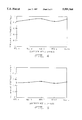
- FIG. 5 is a graph illustrating the medial/lateral bending stiffness of the five different composite rods labeled in FIG. 4;
- FIG. 6 is a graph illustrating the anterior/posterior bending stiffness of the five different composite rods labeled in FIG. 4;
- FIG. 7 is a graph illustrating the axial compression stiffness of the five different composite rods labeled in FIG. 4.
- External fixator assembly 10 which is used to fixate and stabilize fracture 12 of bone 14.
- External fixator assembly 10 includes a hexagonal fixation rod 16, to be described in more detail hereinafter, which is disposed generally parallel with bone 14.
- Fixation pins 18 include respective threaded ends 20 which are screwed into bone 14 at desired locations.
- a plurality of clamp assemblies 22 respectively interconnect at least one fixation pin 18 with fixation rod 16.
- Each clamp assembly 22 includes a body 24 with at least one first opening 25 for receiving fixation rod 16, and at least one second opening for receiving fixation pin 18.
- Body 24 is adapted to threadingly receive a retaining nut 26 associated with a fixation pin 18, and a retaining nut 28 associated with fixation rod 16.
- the lowermost clamp assembly 22 has two retaining nuts 26, but only engages one fixation pin 18. It is to be understood, however, that a clamp assembly 22 having two retaining nuts 26 can engage more than one fixation pin 18 if desirable for a particular application.
- Fixation rod 16 shown in FIGS. 1-3 includes seven separate laminae bound together by a resin, which together form a solid fixation rod.
- the first lamina 32 includes polyester fibers which are oriented at a zero degree angle relative to a longitudinal axis 34 of fixation rod 16. That is, polyester fibers 32 are oriented generally parallel to longitudinal axis 34.
- Second lamina 36 includes glass fibers which are oriented at a zero degree angle relative to longitudinal axis 34.
- Third lamina 38 includes polyester fibers oriented at a zero degree angle relative to longitudinal axis 34.
- Fourth lamina 40 includes carbon fibers which are woven together and oriented at respective 45° angles relative to longitudinal axis 34.
- Fifth lamina 42 includes glass fibers oriented at an 82° angle relative to longitudinal axis 34.
- Sixth lamina 44 includes glass fibers oriented at a zero degree angle relative to longitudinal axis 34.
- Seventh lamina 46 includes polyester fibers oriented at an 82° angle relative to longitudinal axis 34.
- Seventh lamina 46 and fifth lamina 42 are disposed at opposite angles relative to longitudinal axis 34.
- Laminae 32, 36, 38, 40, 42, 44 and 46 are positioned concentrically about longitudinal axis 34, as shown in FIG. 3.
- the fixation rod described above with reference to FIGS. 2 and 3 includes seven laminae with the respective fiber orientations as indicated.
- the orientation of the fibers within each lamina making up the composite fixation rod determine the torsional, bending, and axial compression stiffness of the rod.
- By varying the angles of the fibers in one or more layers with respect to the longitudinal axis of the rod it is possible to modify the stiffness of the rod in a particular desired direction.
- fourth lamina 40 including woven carbon layers disposed at a 45° angle relative to longitudinal axis 34 primarily control the torsional stiffness of fixation rod 16.
- By varying the angle of the carbon fibers in fourth lamina 40, or the angle of the fibers in other laminae it is possible to affect the torsional, bending and axial compression stiffnesses of fixation rod 16.
- FIGS. 4-7 illustrate stiffnesses of five different composite fixation rods in the torsional, medial/lateral bending, anterior/posterior bending and axial compression directions.
- Each of the fixation rods is a hexagonal rod having dimensions of 0.495 ⁇ 0.005 inch across the flats and 0.577 from corner to corner.
- the following tables set forth the number of laminae making up each rod illustrated in FIGS. 4-7, the type of material for each lamina, the moment of inertia (I) for each lamina and the orientation of the fibers within each lamina relative to the longitudinal axis of the rod:
- the fiberglass listed in the above tables for fixation rods A-E is an E fiberglass; the carbon has a tensile modulus of about 32 ⁇ 10 6 PSI; and the polyester has a tensile strength of about 1.4 ⁇ 10 6 PSI.
- the data illustrated in FIGS. 4-6 was obtained by attaching the five different fixation rods set forth immediately above to a simulated bone using a plurality of clamp assemblies and fixation pins as described above.
- the label "M/L Bending Stiffness” in FIG. 5 indicates the medial/lateral bending stiffness of the fixation rods; and the label “A/P Bending Stiffness” in FIG. 6 indicates the anterior/posterior bending stiffness of the fixation rod.
- the medial/lateral bending stiffness generally corresponds to a direction lying in a plane containing both the simulated bone and the fixation rod.
- the stiffness in the torsional, medial/lateral bending and anterior/posterior bending directions does not vary significantly from one composite rod to another.
- the percentage change for the torsional stiffness and bending stiffness of the composite rods is relatively small when calculated as a percentage change.
- the axial compression stiffness varies much more dramatically than the torsional and bending stiffnesses. It is thus possible with the present invention to provide a plurality of fixation rods having the same exterior geometry and which include substantially constant torsional and bending stiffnesses while varying the axial compression stiffness.
- a fixation rod of the present invention having a modulus of elasticity of between about 2-20 ⁇ 10 6 PSI.
- Bone has a modulus of elasticity of about 2 ⁇ 10 6 PSI and titanium has a modulus of elasticity of about 16 ⁇ 10 6 PSI. It is therefore possible with the present invention to select a fixation rod having an axial compression stiffness ranging from that of bone to that of titanium.
Abstract
Description
______________________________________
Lamina No.  Material    I       Orientation
______________________________________
Rod A:
1           Polyester   2.94E-5 0°
2           Fiberglass  4.39E-4 0°
3           Polyester   8.68E-4 0°
4           Carbon      8.19E-4 ±45°
5           Fiberglass  2.01E-4 +82°
6           Fiberglass  1.19E-3 0°
7           Polyester   2.05E-4 -82°
Rod B:
1           Polyester   5.49E-4 0°
2           Fiberglass  4.27E-4 0°
3           Polyester   3.58E-4 0°
4           Carbon      8.21E-4 ±45°
5           Fiberglass  2.01E-4 +82°
6           Fiberglass  1.19E-3 0°
7           Polyester   2.06E-4 -82°
Rod C (Hollow with plugged ends; I.D. = 0.324):
1           Fiberglass  4.38E-4 ±45°
2           Carbon      7.15E-4 ±45°
3           Fiberglass  1.58E-4 +82°
4           Fiberglass  1.69E-3 0°
5           Polyester   2.05E-4 -82°
Rod D (Hollow with plugged ends):
1           Fiberglass  3.68E-4 ±70°
2           Carbon      8.09E-4 ±45°
3           Fiberglass  1.98E-4 +82°
4           Fiberglass  1.25E-3 0°
5           Polyester   2.05E-4 -82°
Rod E (Hollow with plugged ends):
1           Fiberglass  3.76E-4 ±70°
2           Carbon      8.21E-4 ±45°
3           Fiberglass  2.01E-4 +82°
4           Fiberglass  1.19E-3 0°
5           Fiberglass  2.06E-4 -82°
______________________________________
Claims (9)
Priority Applications (5)
| Application Number | Priority Date | Filing Date | Title |
|---|---|---|---|
| US08/361,779 US5591164A (en) | 1994-12-22 | 1994-12-22 | External fixation apparatus and system |
| AU37936/95A AU680782B2 (en) | 1994-12-22 | 1995-11-20 | External fixation apparatus and system |
| CA002165365A CA2165365C (en) | 1994-12-22 | 1995-12-15 | External fixation apparatus and system |
| EP95203540A EP0717968B1 (en) | 1994-12-22 | 1995-12-18 | External fixation apparatus and system |
| DE69516989T DE69516989T2 (en) | 1994-12-22 | 1995-12-18 | External fixation device and device |
Applications Claiming Priority (1)
| Application Number | Priority Date | Filing Date | Title |
|---|---|---|---|
| US08/361,779 US5591164A (en) | 1994-12-22 | 1994-12-22 | External fixation apparatus and system |
Publications (1)
| Publication Number | Publication Date |
|---|---|
| US5591164A true US5591164A (en) | 1997-01-07 |
Family
ID=23423415
Family Applications (1)
| Application Number | Title | Priority Date | Filing Date |
|---|---|---|---|
| US08/361,779 Expired - Lifetime US5591164A (en) | 1994-12-22 | 1994-12-22 | External fixation apparatus and system |
Country Status (5)
| Country | Link |
|---|---|
| US (1) | US5591164A (en) |
| EP (1) | EP0717968B1 (en) |
| AU (1) | AU680782B2 (en) |
| CA (1) | CA2165365C (en) |
| DE (1) | DE69516989T2 (en) |
Cited By (42)
| Publication number | Priority date | Publication date | Assignee | Title |
|---|---|---|---|---|
| US5951556A (en) * | 1996-05-15 | 1999-09-14 | Orthofix S.R.L. | Compact external fixation device |
| US6024745A (en) * | 1997-05-21 | 2000-02-15 | Orthofix, S.R.L. | External minisplint device |
| US6423061B1 (en) | 2000-03-14 | 2002-07-23 | Amei Technologies Inc. | High tibial osteotomy method and apparatus |
| US6428540B1 (en) | 1996-11-13 | 2002-08-06 | Synthes (U.S.A.) | Device for repositioning fractured bone fragments |
| US6500177B1 (en) | 1998-05-19 | 2002-12-31 | Synthes (Usa) | Telescopic body for an external fixation system |
| US6506612B2 (en) | 1989-12-18 | 2003-01-14 | Princeton Biomeditech Corporation | Immunoassay devices and materials |
| US6678562B1 (en) | 2000-01-12 | 2004-01-13 | Amei Technologies Inc. | Combined tissue/bone growth stimulator and external fixation device |
| US20050085810A1 (en) * | 2003-10-06 | 2005-04-21 | Stryker Trauma Sa | External fixation element |
| US20060229604A1 (en) * | 2005-03-18 | 2006-10-12 | Olsen Ron A | Adjustable splint for osteosynthesis with modular components |
| US20060229605A1 (en) * | 2005-03-18 | 2006-10-12 | Olsen Ron A | Adjustable splint for osteosynthesis with incrementing assembly for adjustment in predetermined increments |
| US20060247629A1 (en) * | 2005-04-27 | 2006-11-02 | Maughan Thomas J | Bone fixation apparatus |
| US20070162028A1 (en) * | 2005-12-09 | 2007-07-12 | Jesse Jackson | Cannulated screw |
| US20070270821A1 (en) * | 2006-04-28 | 2007-11-22 | Sdgi Holdings, Inc. | Vertebral stabilizer |
| US20080086127A1 (en) * | 2006-08-31 | 2008-04-10 | Warsaw Orthopedic, Inc. | Polymer Rods For Spinal Applications |
| US20080177388A1 (en) * | 2007-01-18 | 2008-07-24 | Warsaw Orthopedic, Inc. | Variable Stiffness Support Members |
| US20080234736A1 (en) * | 2007-02-28 | 2008-09-25 | Warsaw Orthopedic, Inc. | Vertebral Stabilizer |
| US20090005817A1 (en) * | 2007-04-30 | 2009-01-01 | Adam Friedrich | Flexible Spine Stabilization System |
| US9179940B2 (en) | 2005-12-06 | 2015-11-10 | Globus Medical, Inc. | System and method for replacement of spinal motion segment |
| US9301782B2 (en) | 2012-09-04 | 2016-04-05 | Zimmer, Inc. | External fixation |
| US9539029B1 (en) | 2015-12-03 | 2017-01-10 | Globus Medical, Inc. | External fixator assembly |
| US20170209177A1 (en) * | 2014-07-25 | 2017-07-27 | The General Hospital Corporation | System and method for an external hip fixator |
| US9924969B2 (en) | 2012-09-04 | 2018-03-27 | Zimmer, Inc. | External fixation |
| US9943337B2 (en) | 2015-12-03 | 2018-04-17 | Globus Medical, Inc. | External fixator assembly |
| US9962187B2 (en) | 2014-08-11 | 2018-05-08 | Zimmer, Inc. | External fixation |
| US9962188B2 (en) | 2013-10-29 | 2018-05-08 | Cardinal Health 247. Inc. | External fixation system and methods of use |
| US10136919B2 (en) | 2015-12-03 | 2018-11-27 | Globus Medical, Inc. | External fixator assembly |
| US11013545B2 (en) | 2018-05-30 | 2021-05-25 | Acumed Llc | Distraction/compression apparatus and method for bone |
| US11109802B2 (en) | 2016-01-11 | 2021-09-07 | Kambiz Behzadi | Invasive sense measurement in prosthesis installation and bone preparation |
| US11116639B2 (en) | 2016-04-07 | 2021-09-14 | Kambiz Behzadi | Mechanical assembly including exterior surface preparation |
| US11134988B2 (en) | 2015-06-17 | 2021-10-05 | Zimmer, Inc. | Ankle fixation system |
| US11234840B2 (en) | 2016-01-11 | 2022-02-01 | Kambiz Behzadi | Bone preparation apparatus and method |
| US11241248B2 (en) | 2016-01-11 | 2022-02-08 | Kambiz Behzadi | Bone preparation apparatus and method |
| US11298102B2 (en) | 2016-01-11 | 2022-04-12 | Kambiz Behzadi | Quantitative assessment of prosthesis press-fit fixation |
| US11331069B2 (en) | 2016-01-11 | 2022-05-17 | Kambiz Behzadi | Invasive sense measurement in prosthesis installation |
| US11375975B2 (en) | 2016-01-11 | 2022-07-05 | Kambiz Behzadi | Quantitative assessment of implant installation |
| US11399946B2 (en) | 2016-01-11 | 2022-08-02 | Kambiz Behzadi | Prosthesis installation and assembly |
| US11406504B2 (en) | 2016-06-12 | 2022-08-09 | Kambiz Behzadi | Mechanical assembly including exterior surface preparation |
| US11458028B2 (en) | 2016-01-11 | 2022-10-04 | Kambiz Behzadi | Prosthesis installation and assembly |
| US11534314B2 (en) | 2016-01-11 | 2022-12-27 | Kambiz Behzadi | Quantitative assessment of prosthesis press-fit fixation |
| US11672566B2 (en) | 2015-12-03 | 2023-06-13 | Globus Medical, Inc. | External fixator assembly |
| US11717310B2 (en) | 2016-01-11 | 2023-08-08 | Kambiz Behzadi | Bone preparation apparatus and method |
| US11751807B2 (en) | 2016-01-11 | 2023-09-12 | Kambiz Behzadi | Invasive sense measurement in prosthesis installation and bone preparation |
Families Citing this family (3)
| Publication number | Priority date | Publication date | Assignee | Title |
|---|---|---|---|---|
| ATE349960T1 (en) * | 1997-01-14 | 2007-01-15 | Res Corp Technologies Inc | BONE PIN WITH ROTARY CUTTING TIP |
| EP1522267B1 (en) * | 2003-10-06 | 2009-01-14 | Stryker Trauma SA | External fixation elements |
| GB0607535D0 (en) * | 2006-04-13 | 2006-05-24 | Fixator Innovations Ltd | Fixator member |
Citations (29)
| Publication number | Priority date | Publication date | Assignee | Title |
|---|---|---|---|---|
| US4308863A (en) * | 1979-10-18 | 1982-01-05 | Ace Orthopedic Manufacturing, Inc. | External fixation device |
| US4365624A (en) * | 1979-01-16 | 1982-12-28 | Jaquet Orthopedie Sa | External bone-anchoring element |
| US4584995A (en) * | 1984-04-26 | 1986-04-29 | Orthotic Limited Partnership | External fixation device |
| US4620533A (en) * | 1985-09-16 | 1986-11-04 | Pfizer Hospital Products Group Inc. | External bone fixation apparatus |
| US4624249A (en) * | 1984-12-04 | 1986-11-25 | Medicuba | Orthopedic external fixing apparatus |
| US4747400A (en) * | 1984-04-26 | 1988-05-31 | Harrington Arthritis Research Center | External fixation device |
| US4768524A (en) * | 1986-02-28 | 1988-09-06 | Hardy Jean Marie | Device for immobilizing a bone structure, especially intended for orthopedic use |
| US4784125A (en) * | 1985-01-24 | 1988-11-15 | Jaquet Orthopedie, S. A. | Arcuate element and external fixation device containing same for osteosynthesis and osteoplasty |
| US4889111A (en) * | 1984-02-08 | 1989-12-26 | Ben Dov Meir | Bone growth stimulator |
| US4893618A (en) * | 1986-08-26 | 1990-01-16 | Wolfgang Herzberg | External fixation apparatus |
| US4895141A (en) * | 1984-04-26 | 1990-01-23 | Harrington Arthritis Research Center | Unilateral external fixation device |
| US4902297A (en) * | 1986-03-03 | 1990-02-20 | Zimmer, Inc. | Composite implant prosthesis |
| US4923458A (en) * | 1986-04-17 | 1990-05-08 | Ace Medical Company | Surgical fixation pin tension adjuster |
| US4936843A (en) * | 1989-02-16 | 1990-06-26 | Ace Orthopedic Manufacturing | Kirschner wire clamp and tensioner |
| US4941481A (en) * | 1985-11-29 | 1990-07-17 | Jaquet Orthopedie, S.A. | Device for positioning and securing a part having circular regions |
| US4978358A (en) * | 1988-10-06 | 1990-12-18 | Zimmer Inc. | Orthopaedic prosthetic device possessing improved composite stem design |
| US4978360A (en) * | 1986-03-03 | 1990-12-18 | Zimmer, Inc. | Method of manufacturing a composite implant prosthesis |
| US5021054A (en) * | 1989-03-22 | 1991-06-04 | Ortomedical S.R.L. | Extrafocal fixing apparatus for transosteal syndesis of strains and compressions in orthopedics and traumatology |
| US5067954A (en) * | 1988-07-25 | 1991-11-26 | Ilizarov Gavriil A | Distraction apparatus for plastic reconstruction of hand |
| US5087258A (en) * | 1987-06-19 | 1992-02-11 | Thomas Schewior | Ring splint to set, affix and regulate the tension position of bone segments |
| US5112331A (en) * | 1989-06-15 | 1992-05-12 | Vel Miletich | Orthopedic pins for external fixator |
| US5163962A (en) * | 1990-08-30 | 1992-11-17 | Bhc Laboratories, Inc. | Composite femoral implant having increased neck strength |
| US5167661A (en) * | 1989-09-27 | 1992-12-01 | Jaquet Orthopedie S.A. | Device for articulation and relative locking of two pieces |
| US5181930A (en) * | 1991-04-10 | 1993-01-26 | Pfizer Hospital Products Group, Inc. | Composite orthopedic implant |
| US5192330A (en) * | 1987-01-20 | 1993-03-09 | Smith & Nephew Richards, Inc. | Orthopedic device of biocompatible polymer with oriented fiber reinforcement |
| US5209750A (en) * | 1990-10-12 | 1993-05-11 | Compagnie General De Materiel Orthopedique | External holding and reducing brace for bone fractures |
| US5219363A (en) * | 1988-03-22 | 1993-06-15 | Zimmer, Inc. | Bone implant |
| US5275598A (en) * | 1991-10-09 | 1994-01-04 | Cook Richard L | Quasi-isotropic apparatus and method of fabricating the apparatus |
| US5350378A (en) * | 1993-05-19 | 1994-09-27 | Cole J Dean | Posterior external pelvic fixator |
Family Cites Families (4)
| Publication number | Priority date | Publication date | Assignee | Title |
|---|---|---|---|---|
| US1793393A (en) | 1928-10-30 | 1931-02-17 | Glaenzer Harry | End frame of locomotives |
| DE2745504A1 (en) * | 1977-10-10 | 1979-04-19 | Erich Strickle | DEVICE FOR RESTING OR SUPPORTING LIMBS OF PEOPLE AND ANIMALS |
| GB2104782B (en) * | 1981-08-06 | 1984-11-28 | Nat Res Dev | Fracture fixator |
| FR2529778B1 (en) * | 1982-07-09 | 1985-10-25 | Paris Ecole Nale Sup Arts Meti | FIXING DEVICE FOR IMMOBILIZING LONG BONES WITH OPEN FRACTURE |
-
1994
- 1994-12-22 US US08/361,779 patent/US5591164A/en not_active Expired - Lifetime
-
1995
- 1995-11-20 AU AU37936/95A patent/AU680782B2/en not_active Ceased
- 1995-12-15 CA CA002165365A patent/CA2165365C/en not_active Expired - Fee Related
- 1995-12-18 DE DE69516989T patent/DE69516989T2/en not_active Expired - Fee Related
- 1995-12-18 EP EP95203540A patent/EP0717968B1/en not_active Expired - Lifetime
Patent Citations (32)
| Publication number | Priority date | Publication date | Assignee | Title |
|---|---|---|---|---|
| US4365624A (en) * | 1979-01-16 | 1982-12-28 | Jaquet Orthopedie Sa | External bone-anchoring element |
| US4535763A (en) * | 1979-01-16 | 1985-08-20 | Jaquet Orthopedic S.A. | External bone-anchoring element |
| US4308863A (en) * | 1979-10-18 | 1982-01-05 | Ace Orthopedic Manufacturing, Inc. | External fixation device |
| US4889111A (en) * | 1984-02-08 | 1989-12-26 | Ben Dov Meir | Bone growth stimulator |
| US4895141A (en) * | 1984-04-26 | 1990-01-23 | Harrington Arthritis Research Center | Unilateral external fixation device |
| US4584995A (en) * | 1984-04-26 | 1986-04-29 | Orthotic Limited Partnership | External fixation device |
| US4747400A (en) * | 1984-04-26 | 1988-05-31 | Harrington Arthritis Research Center | External fixation device |
| US4624249A (en) * | 1984-12-04 | 1986-11-25 | Medicuba | Orthopedic external fixing apparatus |
| US5095919A (en) * | 1985-01-24 | 1992-03-17 | Jaquet Orthopedie S.A. | Arcuate element and external fixation device |
| US4784125A (en) * | 1985-01-24 | 1988-11-15 | Jaquet Orthopedie, S. A. | Arcuate element and external fixation device containing same for osteosynthesis and osteoplasty |
| US4620533A (en) * | 1985-09-16 | 1986-11-04 | Pfizer Hospital Products Group Inc. | External bone fixation apparatus |
| US4941481A (en) * | 1985-11-29 | 1990-07-17 | Jaquet Orthopedie, S.A. | Device for positioning and securing a part having circular regions |
| US5098432A (en) * | 1985-11-29 | 1992-03-24 | Jaquet Orthopedie S.A. | Device for positioning and securing a part having circular regions |
| US4768524A (en) * | 1986-02-28 | 1988-09-06 | Hardy Jean Marie | Device for immobilizing a bone structure, especially intended for orthopedic use |
| US4902297A (en) * | 1986-03-03 | 1990-02-20 | Zimmer, Inc. | Composite implant prosthesis |
| US4978360A (en) * | 1986-03-03 | 1990-12-18 | Zimmer, Inc. | Method of manufacturing a composite implant prosthesis |
| US4923458A (en) * | 1986-04-17 | 1990-05-08 | Ace Medical Company | Surgical fixation pin tension adjuster |
| US4893618A (en) * | 1986-08-26 | 1990-01-16 | Wolfgang Herzberg | External fixation apparatus |
| US5192330A (en) * | 1987-01-20 | 1993-03-09 | Smith & Nephew Richards, Inc. | Orthopedic device of biocompatible polymer with oriented fiber reinforcement |
| US5087258A (en) * | 1987-06-19 | 1992-02-11 | Thomas Schewior | Ring splint to set, affix and regulate the tension position of bone segments |
| US5219363A (en) * | 1988-03-22 | 1993-06-15 | Zimmer, Inc. | Bone implant |
| US5067954A (en) * | 1988-07-25 | 1991-11-26 | Ilizarov Gavriil A | Distraction apparatus for plastic reconstruction of hand |
| US4978358A (en) * | 1988-10-06 | 1990-12-18 | Zimmer Inc. | Orthopaedic prosthetic device possessing improved composite stem design |
| US4936843A (en) * | 1989-02-16 | 1990-06-26 | Ace Orthopedic Manufacturing | Kirschner wire clamp and tensioner |
| US5021054A (en) * | 1989-03-22 | 1991-06-04 | Ortomedical S.R.L. | Extrafocal fixing apparatus for transosteal syndesis of strains and compressions in orthopedics and traumatology |
| US5112331A (en) * | 1989-06-15 | 1992-05-12 | Vel Miletich | Orthopedic pins for external fixator |
| US5167661A (en) * | 1989-09-27 | 1992-12-01 | Jaquet Orthopedie S.A. | Device for articulation and relative locking of two pieces |
| US5163962A (en) * | 1990-08-30 | 1992-11-17 | Bhc Laboratories, Inc. | Composite femoral implant having increased neck strength |
| US5209750A (en) * | 1990-10-12 | 1993-05-11 | Compagnie General De Materiel Orthopedique | External holding and reducing brace for bone fractures |
| US5181930A (en) * | 1991-04-10 | 1993-01-26 | Pfizer Hospital Products Group, Inc. | Composite orthopedic implant |
| US5275598A (en) * | 1991-10-09 | 1994-01-04 | Cook Richard L | Quasi-isotropic apparatus and method of fabricating the apparatus |
| US5350378A (en) * | 1993-05-19 | 1994-09-27 | Cole J Dean | Posterior external pelvic fixator |
Non-Patent Citations (1)
| Title |
|---|
| Zimmer Brochure, Fracture Management, Torus External Fixation System. * |
Cited By (76)
| Publication number | Priority date | Publication date | Assignee | Title |
|---|---|---|---|---|
| US6506612B2 (en) | 1989-12-18 | 2003-01-14 | Princeton Biomeditech Corporation | Immunoassay devices and materials |
| US6541277B1 (en) | 1989-12-18 | 2003-04-01 | Princeton Biomeditech Corporation | Immunoassay devices and materials |
| US6737277B1 (en) | 1989-12-18 | 2004-05-18 | Pmb-Selfcare Llc | Immunoassay devices and materials |
| US5951556A (en) * | 1996-05-15 | 1999-09-14 | Orthofix S.R.L. | Compact external fixation device |
| US6428540B1 (en) | 1996-11-13 | 2002-08-06 | Synthes (U.S.A.) | Device for repositioning fractured bone fragments |
| US6024745A (en) * | 1997-05-21 | 2000-02-15 | Orthofix, S.R.L. | External minisplint device |
| US6500177B1 (en) | 1998-05-19 | 2002-12-31 | Synthes (Usa) | Telescopic body for an external fixation system |
| US6678562B1 (en) | 2000-01-12 | 2004-01-13 | Amei Technologies Inc. | Combined tissue/bone growth stimulator and external fixation device |
| US6423061B1 (en) | 2000-03-14 | 2002-07-23 | Amei Technologies Inc. | High tibial osteotomy method and apparatus |
| US20020164905A1 (en) * | 2000-03-14 | 2002-11-07 | Amei Technologies Inc., A Delaware Corporation | Osteotomy guide and method |
| US20050085810A1 (en) * | 2003-10-06 | 2005-04-21 | Stryker Trauma Sa | External fixation element |
| US7527626B2 (en) | 2003-10-06 | 2009-05-05 | Stryker Trauma Sa | External fixation element |
| US7575575B2 (en) | 2005-03-18 | 2009-08-18 | Ron Anthon Olsen | Adjustable splint for osteosynthesis with modular components |
| US7507240B2 (en) | 2005-03-18 | 2009-03-24 | Ron Anthon Olsen | Adjustable splint for osteosynthesis |
| US20060229602A1 (en) * | 2005-03-18 | 2006-10-12 | Olsen Ron A | Adjustable splint for osteosynthesis |
| US7588571B2 (en) | 2005-03-18 | 2009-09-15 | Ron Anthon Olsen | Adjustable splint for osteosynthesis with modular joint |
| US20060229603A1 (en) * | 2005-03-18 | 2006-10-12 | Olsen Ron A | Adjustable splint for osteosynthesis with modular joint |
| US20060229604A1 (en) * | 2005-03-18 | 2006-10-12 | Olsen Ron A | Adjustable splint for osteosynthesis with modular components |
| US20060229605A1 (en) * | 2005-03-18 | 2006-10-12 | Olsen Ron A | Adjustable splint for osteosynthesis with incrementing assembly for adjustment in predetermined increments |
| US20060247629A1 (en) * | 2005-04-27 | 2006-11-02 | Maughan Thomas J | Bone fixation apparatus |
| US8758343B2 (en) | 2005-04-27 | 2014-06-24 | DePuy Synthes Products, LLC | Bone fixation apparatus |
| US8343166B2 (en) * | 2005-04-27 | 2013-01-01 | Synthes Usa, Llc | Bone fixation apparatus |
| US9179940B2 (en) | 2005-12-06 | 2015-11-10 | Globus Medical, Inc. | System and method for replacement of spinal motion segment |
| US7731738B2 (en) | 2005-12-09 | 2010-06-08 | Orthopro, Llc | Cannulated screw |
| US20070162028A1 (en) * | 2005-12-09 | 2007-07-12 | Jesse Jackson | Cannulated screw |
| US20070270821A1 (en) * | 2006-04-28 | 2007-11-22 | Sdgi Holdings, Inc. | Vertebral stabilizer |
| US20080086127A1 (en) * | 2006-08-31 | 2008-04-10 | Warsaw Orthopedic, Inc. | Polymer Rods For Spinal Applications |
| US20090261505A1 (en) * | 2006-08-31 | 2009-10-22 | Warsaw Orthopedic, Inc. | Polymer rods for spinal applications |
| US7766942B2 (en) | 2006-08-31 | 2010-08-03 | Warsaw Orthopedic, Inc. | Polymer rods for spinal applications |
| US7968037B2 (en) | 2006-08-31 | 2011-06-28 | Warsaw Orthopedic, Inc. | Polymer rods for spinal applications |
| US7875059B2 (en) | 2007-01-18 | 2011-01-25 | Warsaw Orthopedic, Inc. | Variable stiffness support members |
| US20080177388A1 (en) * | 2007-01-18 | 2008-07-24 | Warsaw Orthopedic, Inc. | Variable Stiffness Support Members |
| US20080234736A1 (en) * | 2007-02-28 | 2008-09-25 | Warsaw Orthopedic, Inc. | Vertebral Stabilizer |
| US8740944B2 (en) | 2007-02-28 | 2014-06-03 | Warsaw Orthopedic, Inc. | Vertebral stabilizer |
| US9339297B2 (en) | 2007-04-30 | 2016-05-17 | Globus Medical, Inc. | Flexible spine stabilization system |
| US9211142B2 (en) | 2007-04-30 | 2015-12-15 | Globus Medical, Inc. | Flexible element for spine stabilization system |
| US9220538B2 (en) | 2007-04-30 | 2015-12-29 | Globus Medical, Inc. | Flexible element for spine stabilization system |
| US20090005817A1 (en) * | 2007-04-30 | 2009-01-01 | Adam Friedrich | Flexible Spine Stabilization System |
| US8465526B2 (en) | 2007-04-30 | 2013-06-18 | Globus Medical, Inc. | Flexible spine stabilization system |
| US10010348B2 (en) | 2012-09-04 | 2018-07-03 | Zimmer, Inc. | External fixation |
| US9301782B2 (en) | 2012-09-04 | 2016-04-05 | Zimmer, Inc. | External fixation |
| US10905469B2 (en) | 2012-09-04 | 2021-02-02 | Zimmer, Inc. | External fixation |
| US10433873B2 (en) | 2012-09-04 | 2019-10-08 | Zimmer, Inc. | External fixation |
| US9924969B2 (en) | 2012-09-04 | 2018-03-27 | Zimmer, Inc. | External fixation |
| US9962188B2 (en) | 2013-10-29 | 2018-05-08 | Cardinal Health 247. Inc. | External fixation system and methods of use |
| US20170209177A1 (en) * | 2014-07-25 | 2017-07-27 | The General Hospital Corporation | System and method for an external hip fixator |
| US10314618B2 (en) * | 2014-07-25 | 2019-06-11 | The General Hospital Corporation | System and method for an external hip fixator |
| US9962187B2 (en) | 2014-08-11 | 2018-05-08 | Zimmer, Inc. | External fixation |
| US10543019B2 (en) | 2014-08-11 | 2020-01-28 | Zimmer, Inc. | External fixation |
| US11134988B2 (en) | 2015-06-17 | 2021-10-05 | Zimmer, Inc. | Ankle fixation system |
| US11672566B2 (en) | 2015-12-03 | 2023-06-13 | Globus Medical, Inc. | External fixator assembly |
| US10136919B2 (en) | 2015-12-03 | 2018-11-27 | Globus Medical, Inc. | External fixator assembly |
| US10433874B2 (en) | 2015-12-03 | 2019-10-08 | Globus Medical, Inc. | External fixator assembly |
| US9872707B2 (en) | 2015-12-03 | 2018-01-23 | Globus Medical, Inc. | External fixator assembly |
| US10828066B2 (en) | 2015-12-03 | 2020-11-10 | Globus Medical, Inc. | External fixator assembly |
| US9539029B1 (en) | 2015-12-03 | 2017-01-10 | Globus Medical, Inc. | External fixator assembly |
| US10499951B2 (en) | 2015-12-03 | 2019-12-10 | Globus Medical, Inc. | External fixator assembly |
| US9943337B2 (en) | 2015-12-03 | 2018-04-17 | Globus Medical, Inc. | External fixator assembly |
| US11298102B2 (en) | 2016-01-11 | 2022-04-12 | Kambiz Behzadi | Quantitative assessment of prosthesis press-fit fixation |
| US11751807B2 (en) | 2016-01-11 | 2023-09-12 | Kambiz Behzadi | Invasive sense measurement in prosthesis installation and bone preparation |
| US11534314B2 (en) | 2016-01-11 | 2022-12-27 | Kambiz Behzadi | Quantitative assessment of prosthesis press-fit fixation |
| US11458028B2 (en) | 2016-01-11 | 2022-10-04 | Kambiz Behzadi | Prosthesis installation and assembly |
| US11896500B2 (en) | 2016-01-11 | 2024-02-13 | Kambiz Behzadi | Bone preparation apparatus and method |
| US11890196B2 (en) | 2016-01-11 | 2024-02-06 | Kambiz Behzadi | Prosthesis installation and assembly |
| US11375975B2 (en) | 2016-01-11 | 2022-07-05 | Kambiz Behzadi | Quantitative assessment of implant installation |
| US11109802B2 (en) | 2016-01-11 | 2021-09-07 | Kambiz Behzadi | Invasive sense measurement in prosthesis installation and bone preparation |
| US11883056B2 (en) | 2016-01-11 | 2024-01-30 | Kambiz Behzadi | Bone preparation apparatus and method |
| US11234840B2 (en) | 2016-01-11 | 2022-02-01 | Kambiz Behzadi | Bone preparation apparatus and method |
| US11241248B2 (en) | 2016-01-11 | 2022-02-08 | Kambiz Behzadi | Bone preparation apparatus and method |
| US11331069B2 (en) | 2016-01-11 | 2022-05-17 | Kambiz Behzadi | Invasive sense measurement in prosthesis installation |
| US11717310B2 (en) | 2016-01-11 | 2023-08-08 | Kambiz Behzadi | Bone preparation apparatus and method |
| US11399946B2 (en) | 2016-01-11 | 2022-08-02 | Kambiz Behzadi | Prosthesis installation and assembly |
| US11786207B2 (en) | 2016-01-11 | 2023-10-17 | Kambiz Behzadi | Invasive sense measurement in prosthesis installation |
| US11116639B2 (en) | 2016-04-07 | 2021-09-14 | Kambiz Behzadi | Mechanical assembly including exterior surface preparation |
| US11406504B2 (en) | 2016-06-12 | 2022-08-09 | Kambiz Behzadi | Mechanical assembly including exterior surface preparation |
| US11013545B2 (en) | 2018-05-30 | 2021-05-25 | Acumed Llc | Distraction/compression apparatus and method for bone |
Also Published As
| Publication number | Publication date |
|---|---|
| EP0717968A2 (en) | 1996-06-26 |
| DE69516989D1 (en) | 2000-06-21 |
| AU3793695A (en) | 1996-06-27 |
| CA2165365A1 (en) | 1996-06-23 |
| EP0717968B1 (en) | 2000-05-17 |
| EP0717968A3 (en) | 1996-11-20 |
| CA2165365C (en) | 2006-05-23 |
| DE69516989T2 (en) | 2000-10-05 |
| AU680782B2 (en) | 1997-08-07 |
Similar Documents
| Publication | Publication Date | Title |
|---|---|---|
| US5591164A (en) | External fixation apparatus and system | |
| US5330474A (en) | Vertebral locking and retrieving system | |
| US5257994A (en) | Vertebral locking and retrieving system | |
| US5891144A (en) | External fixator | |
| US5196014A (en) | Vertebral locking and retrieving system | |
| AU680209B2 (en) | Spinal rod transverse connector for supporting vertebral fixation elements | |
| EP1972289B1 (en) | Elongated stabilization member and bone anchor useful in bone and especially spinal repair processes | |
| US6712820B2 (en) | Fixation plate system for dorsal wrist fracture fixation | |
| US5084048A (en) | Implant for vertebrae with spinal stabilizer | |
| US5437669A (en) | Spinal fixation systems with bifurcated connectors | |
| US6645207B2 (en) | Method and apparatus for dynamized spinal stabilization | |
| US6508819B1 (en) | Method of dorsal wrist fracture fixation | |
| US3977397A (en) | Surgical compression-distraction instrument | |
| US5217461A (en) | Apparatus for maintaining vertebrae in a desired spatial relationship | |
| US8721690B2 (en) | Rod-shaped implant element with flexible section | |
| US4456004A (en) | Fracture holding | |
| Kabins et al. | The history of vertebral screw and pedicle screw fixation | |
| US8308778B2 (en) | Longitudinal implant | |
| EP0609409A1 (en) | External axial fixator for osteosynthesis | |
| US7938849B2 (en) | Method for treating long bone fractures | |
| JPH03500259A (en) | Correction and support devices, specifically for the spinal column | |
| US5403313A (en) | External fixation device for fractured bone | |
| EP0313556B1 (en) | External fixation device | |
| CA2123353A1 (en) | Composite spinal apparatus | |
| RU1771717C (en) | Device for spinal column stabilization |
Legal Events
| Date | Code | Title | Description |
|---|---|---|---|
| AS | Assignment |
Owner name: ZIMMER, INC., INDIANA Free format text: ASSIGNMENT OF ASSIGNORS INTEREST;ASSIGNOR:FISH, ELDON B.;REEL/FRAME:007284/0194 Effective date: 19941219 Owner name: ZIMMER, INC., INDIANA Free format text: ASSIGNMENT OF ASSIGNORS INTEREST;ASSIGNOR:NAZRE, ANIRUDDHA A.;REEL/FRAME:007284/0197 Effective date: 19941220 |
|
| STCF | Information on status: patent grant |
Free format text: PATENTED CASE |
|
| FPAY | Fee payment |
Year of fee payment: 4 |
|
| AS | Assignment |
Owner name: ZIMMER, INC., INDIANA Free format text: ASSIGNMENT OF ASSIGNORS INTEREST;ASSIGNOR:BRISTOL-MYERS SQUIBB COMPANY;REEL/FRAME:012729/0494 Effective date: 20020114 |
|
| AS | Assignment |
Owner name: ZIMMER TECHNOLOGY, INC., ILLINOIS Free format text: ASSIGNMENT OF ASSIGNORS INTEREST;ASSIGNOR:ZIMMER, INC.;REEL/FRAME:013862/0766 Effective date: 20020628 |
|
| FEPP | Fee payment procedure |
Free format text: PAYOR NUMBER ASSIGNED (ORIGINAL EVENT CODE: ASPN); ENTITY STATUS OF PATENT OWNER: LARGE ENTITY |
|
| FPAY | Fee payment |
Year of fee payment: 8 |
|
| FPAY | Fee payment |
Year of fee payment: 12 |
|
| REMI | Maintenance fee reminder mailed |