US5600115A - Flexible cable with security system for code markings - Google Patents
Flexible cable with security system for code markings Download PDFInfo
- Publication number
- US5600115A US5600115A US08/586,987 US58698796A US5600115A US 5600115 A US5600115 A US 5600115A US 58698796 A US58698796 A US 58698796A US 5600115 A US5600115 A US 5600115A
- Authority
- US
- United States
- Prior art keywords
- emitting elements
- component
- transmitting element
- heat
- heat energy
- Prior art date
- Legal status (The legal status is an assumption and is not a legal conclusion. Google has not performed a legal analysis and makes no representation as to the accuracy of the status listed.)
- Expired - Fee Related
Links
Images
Classifications
-
- G—PHYSICS
- G06—COMPUTING; CALCULATING OR COUNTING
- G06K—GRAPHICAL DATA READING; PRESENTATION OF DATA; RECORD CARRIERS; HANDLING RECORD CARRIERS
- G06K19/00—Record carriers for use with machines and with at least a part designed to carry digital markings
- G06K19/06—Record carriers for use with machines and with at least a part designed to carry digital markings characterised by the kind of the digital marking, e.g. shape, nature, code
- G06K19/067—Record carriers with conductive marks, printed circuits or semiconductor circuit elements, e.g. credit or identity cards also with resonating or responding marks without active components
- G06K19/07—Record carriers with conductive marks, printed circuits or semiconductor circuit elements, e.g. credit or identity cards also with resonating or responding marks without active components with integrated circuit chips
- G06K19/077—Constructional details, e.g. mounting of circuits in the carrier
- G06K19/07749—Constructional details, e.g. mounting of circuits in the carrier the record carrier being capable of non-contact communication, e.g. constructional details of the antenna of a non-contact smart card
- G06K19/07758—Constructional details, e.g. mounting of circuits in the carrier the record carrier being capable of non-contact communication, e.g. constructional details of the antenna of a non-contact smart card arrangements for adhering the record carrier to further objects or living beings, functioning as an identification tag
-
- G—PHYSICS
- G06—COMPUTING; CALCULATING OR COUNTING
- G06K—GRAPHICAL DATA READING; PRESENTATION OF DATA; RECORD CARRIERS; HANDLING RECORD CARRIERS
- G06K19/00—Record carriers for use with machines and with at least a part designed to carry digital markings
- G06K19/06—Record carriers for use with machines and with at least a part designed to carry digital markings characterised by the kind of the digital marking, e.g. shape, nature, code
- G06K19/067—Record carriers with conductive marks, printed circuits or semiconductor circuit elements, e.g. credit or identity cards also with resonating or responding marks without active components
- G06K19/07—Record carriers with conductive marks, printed circuits or semiconductor circuit elements, e.g. credit or identity cards also with resonating or responding marks without active components with integrated circuit chips
- G06K19/0723—Record carriers with conductive marks, printed circuits or semiconductor circuit elements, e.g. credit or identity cards also with resonating or responding marks without active components with integrated circuit chips the record carrier comprising an arrangement for non-contact communication, e.g. wireless communication circuits on transponder cards, non-contact smart cards or RFIDs
- G06K19/0728—Record carriers with conductive marks, printed circuits or semiconductor circuit elements, e.g. credit or identity cards also with resonating or responding marks without active components with integrated circuit chips the record carrier comprising an arrangement for non-contact communication, e.g. wireless communication circuits on transponder cards, non-contact smart cards or RFIDs the arrangement being an optical or sound-based communication interface
-
- G—PHYSICS
- G06—COMPUTING; CALCULATING OR COUNTING
- G06K—GRAPHICAL DATA READING; PRESENTATION OF DATA; RECORD CARRIERS; HANDLING RECORD CARRIERS
- G06K19/00—Record carriers for use with machines and with at least a part designed to carry digital markings
- G06K19/06—Record carriers for use with machines and with at least a part designed to carry digital markings characterised by the kind of the digital marking, e.g. shape, nature, code
- G06K19/067—Record carriers with conductive marks, printed circuits or semiconductor circuit elements, e.g. credit or identity cards also with resonating or responding marks without active components
- G06K19/07—Record carriers with conductive marks, printed circuits or semiconductor circuit elements, e.g. credit or identity cards also with resonating or responding marks without active components with integrated circuit chips
- G06K19/077—Constructional details, e.g. mounting of circuits in the carrier
- G06K19/07749—Constructional details, e.g. mounting of circuits in the carrier the record carrier being capable of non-contact communication, e.g. constructional details of the antenna of a non-contact smart card
Definitions
- the present invention relates to information encoding and decoding systems, and more particularly to a flat flexible cable in which an array of conductive elements are arranged.
- the elements emit heat, and are provided with shapes, dimensions, and spacings which together effectively represent a bar code marking.
- the cables with the included elements are designed to be carried within clothing, such as an armband, or otherwise attached to objects which require monitoring, and are employed with a detecting and decoding security system.
- bar code markings applied directly on the product, or indirectly applied to the product by affixing a label or tag bearing the bar code markings.
- Another object of the invention is to provide an apparatus for assigning coded, identifying information to persons or objects for use in a security system where, when the person or object reaches an appropriate location, the information can be detected, and then decoded, to determine whether the object or person should be permitted or denied access to the location.
- Still another object of the invention is to provide a flexible cable with energy emitting elements configured to represent bar code markings for use in an apparatus of the type described above.
- the system of the present invention which comprises an information transmitting member that includes a length of flexible cable supporting an array of energy emitting elements.
- the elements are preferably made of conductive materials, and are of such sizes, shapes and spacings as to collectively represent bar code markings.
- a carrier for the information transmitting element is adapted to be mounted on a person or object, where movement of the person or object from one place to another requires control and where admission to such places might be selectively denied.
- Receiver means is provided for detecting and decoding the encoded information.
- FIG. 1 shows one application of the invention
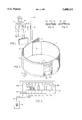
- FIG. 2 is a partial sectional view showing an information transmitting member according to the present invention arranged in a pocket of an armband;
- FIG. 3 is a schematic representation of the information transmitting member showing the array of energy emitting elements
- FIG. 4 is a cross-sectional view of one energy emitting element, made by a subtractive method, and shown in FIG. 3;
- FIG. 5 is a cross-sectional view of a second energy emitting element, made by an additive method, and shown in FIG. 3.
- a person P is shown passing or standing in the vicinity of a support 10, such as a wall or doorpost, in his approach toward one or more "secured” means, i.e., locations where special advance clearances are necessary before admittance is permitted.
- the person is shown to be wearing a band 12 secured about his arm and a conventional power pack 40 of a type which can be carried in the person's shirt pocket.
- the power pack is portable, and it is contemplated that it could also be secured in the person's belt.
- the power pack is attached to the information transmitting member 20 of the present invention described in greater detail below.
- Member 20 is carried in a band 12 by conductive wires 50.
- the signal transmitting means in the band 12 emits a signal S which is detected by signal detecting and decoding apparatus 60 attached to the support post 10.
- FIG. 2 shows a partial sectional view of the arm band 12.
- the band comprises a piece of flexible fabric having a length which is great enough to encircle a well-developed adult human upper arm and includes ends 13 and 14.
- Interengaging, releasable fastening elements are preferably provided on facing portions of the ends 13, 14.
- Fastening elements contemplated for use in the present invention include buttons and button holes, male and female snap members, hook and loop fasteners, etc.
- Arm band 12 is preferably made of a conventional fabric material, such as cotton, rayon, etc.
- a pocket 15 is formed in the arm band between the inner and outer layers 16, 17, and is accessable through a window or slot 18 in the outer layer 17.
- An encoded information transmitting member 20 in accordance with the present invention is shown inserted in the pocket 15 of the armband 12.
- FIG. 3 schematically shows the information transmitting member 20 of the present invention.
- Member 20 includes a flat flexible insulating substrate 22 on which conductive members 23a, 23b, 23c, . . . , 23n are disposed. Heating of the cable member 20 is accomplished in a manner similar to that disclosed in applicant's prior U.S. Pat. No. 4,948,951.
- the conductive members 23a, 23b, 23c, . . . 23n are made of copper or another highly conductive metallic material, and are formed either through a subtractive process, such as etching (see the cross-section of member 23a in FIG. 4), or an additive process, such as applying a conductive layer of ink to the substrate (see the cross-section of member 23b in FIG. 5).
- the wires 50 connect the power pack 40 with conductive lands or pads 24 located at an edge of the substrate 22.
- the wires could be soldered to the lands 24 or mechanically secured to the lands via conductive clips.
- the members 23a, 23b, 23c, . . . 23n are preferably formed on one surface of the substrate 22, and have varying lengths, shapes and spacings.
- a conductive path 26a connects one land 24a with one end of each of the members 23a, 23b, 23c, . . . , 23n, and a second conductive path 26b connects the other land 24b with the other end of the members 23a, 23b, 23c, . . . 23n to form an electrical circuit.
- the members 23a, 23b, 23c, . . . 23n act as resistors in the circuit and heat up to a temperature level where infrared radiation is emitted. Due to their width, height, shape and spacing, the members 23a, 23b, 23c, . . . 23n collectively present a thermal signal representative of a code marking (as a result of the variations in height, shape and spacing)when heated to the infrared radiation emitting temperature.
- the invention contemplates that the signal reading apparatus 60 could be an electro-optical detection system, with detectors positioned wherever required to monitor the locations over which control is required.
- the invention further contemplates that the widths, heights, shapes and spacings of the heat emitting members 23a, 23b, 23c, . . . 23n could be so varied as to create an infinite number of codes.
Abstract
A system which includes an information transmitting element including flexible length of cable supporting an array of energy emitting elements of such sizes, shapes and spacings as to represent bar code markings, a carrier for the information transmitting element which is adapted to be mounted on a person or object, where its movement from one place to another requires control and where its admission to such places might be selectively denied, and a receiver element for detecting and determining the encoded information being transmitted.
Description
1. Field of the Invention
The present invention relates to information encoding and decoding systems, and more particularly to a flat flexible cable in which an array of conductive elements are arranged. The elements emit heat, and are provided with shapes, dimensions, and spacings which together effectively represent a bar code marking. The cables with the included elements are designed to be carried within clothing, such as an armband, or otherwise attached to objects which require monitoring, and are employed with a detecting and decoding security system.
2. Description of the Related Art
It is well-known in the prior art to encode information pertaining to particular products in bar code markings, and to apply such bar code markings to such products. This encoded information can be "read" by suitable equipment, such as optical scanners, and then decoded.
Typically, bar code markings applied directly on the product, or indirectly applied to the product by affixing a label or tag bearing the bar code markings.
It is further well known to apply bar code markings to products for security purposes, as for example to prevent unauthorized removal of products from desired areas of storage or access.
Against this background of known technology, it would be desirable to use bar code representations as indicia for controlling access to secured areas, where the indicia are able to be carried on the objects to be granted or denied access.
It is therefore an object of the present invention to provide a novel apparatus for encoding information for use in the identification of objects, especially in connection with security systems, and which will overcome all the deficiencies and drawbacks of similar systems currently known.
Another object of the invention is to provide an apparatus for assigning coded, identifying information to persons or objects for use in a security system where, when the person or object reaches an appropriate location, the information can be detected, and then decoded, to determine whether the object or person should be permitted or denied access to the location.
Still another object of the invention is to provide a flexible cable with energy emitting elements configured to represent bar code markings for use in an apparatus of the type described above.
These and other objects are attained by the system of the present invention which comprises an information transmitting member that includes a length of flexible cable supporting an array of energy emitting elements. The elements are preferably made of conductive materials, and are of such sizes, shapes and spacings as to collectively represent bar code markings. A carrier for the information transmitting element is adapted to be mounted on a person or object, where movement of the person or object from one place to another requires control and where admission to such places might be selectively denied. Receiver means is provided for detecting and decoding the encoded information.
FIG. 1 shows one application of the invention;
FIG. 2 is a partial sectional view showing an information transmitting member according to the present invention arranged in a pocket of an armband;
FIG. 3 is a schematic representation of the information transmitting member showing the array of energy emitting elements;
FIG. 4 is a cross-sectional view of one energy emitting element, made by a subtractive method, and shown in FIG. 3; and
FIG. 5 is a cross-sectional view of a second energy emitting element, made by an additive method, and shown in FIG. 3.
The following detailed description is of the best currently contemplated modes of carrying out the invention. The description is not to be taken in a limiting sense, but is made merely for the purpose of illustrating the general principles of the invention, since the actual scope of the invention can be best determined by the appended claims.
Referring now to FIG. 1, a person P is shown passing or standing in the vicinity of a support 10, such as a wall or doorpost, in his approach toward one or more "secured" means, i.e., locations where special advance clearances are necessary before admittance is permitted.
The person is shown to be wearing a band 12 secured about his arm and a conventional power pack 40 of a type which can be carried in the person's shirt pocket. The power pack is portable, and it is contemplated that it could also be secured in the person's belt.
The power pack is attached to the information transmitting member 20 of the present invention described in greater detail below. Member 20 is carried in a band 12 by conductive wires 50. The signal transmitting means in the band 12 emits a signal S which is detected by signal detecting and decoding apparatus 60 attached to the support post 10.
FIG. 2 shows a partial sectional view of the arm band 12. The band comprises a piece of flexible fabric having a length which is great enough to encircle a well-developed adult human upper arm and includes ends 13 and 14.
Interengaging, releasable fastening elements are preferably provided on facing portions of the ends 13, 14. Fastening elements contemplated for use in the present invention include buttons and button holes, male and female snap members, hook and loop fasteners, etc.
FIG. 3 schematically shows the information transmitting member 20 of the present invention. Member 20 includes a flat flexible insulating substrate 22 on which conductive members 23a, 23b, 23c, . . . , 23n are disposed. Heating of the cable member 20 is accomplished in a manner similar to that disclosed in applicant's prior U.S. Pat. No. 4,948,951.
Preferably, the conductive members 23a, 23b, 23c, . . . 23n are made of copper or another highly conductive metallic material, and are formed either through a subtractive process, such as etching (see the cross-section of member 23a in FIG. 4), or an additive process, such as applying a conductive layer of ink to the substrate (see the cross-section of member 23b in FIG. 5).
The wires 50 connect the power pack 40 with conductive lands or pads 24 located at an edge of the substrate 22. The wires could be soldered to the lands 24 or mechanically secured to the lands via conductive clips.
The members 23a, 23b, 23c, . . . 23n are preferably formed on one surface of the substrate 22, and have varying lengths, shapes and spacings. A conductive path 26a connects one land 24a with one end of each of the members 23a, 23b, 23c, . . . , 23n, and a second conductive path 26b connects the other land 24b with the other end of the members 23a, 23b, 23c, . . . 23n to form an electrical circuit.
When the power pack is activated, the members 23a, 23b, 23c, . . . 23n act as resistors in the circuit and heat up to a temperature level where infrared radiation is emitted. Due to their width, height, shape and spacing, the members 23a, 23b, 23c, . . . 23n collectively present a thermal signal representative of a code marking (as a result of the variations in height, shape and spacing)when heated to the infrared radiation emitting temperature.
The invention contemplates that the signal reading apparatus 60 could be an electro-optical detection system, with detectors positioned wherever required to monitor the locations over which control is required. The invention further contemplates that the widths, heights, shapes and spacings of the heat emitting members 23a, 23b, 23c, . . . 23n could be so varied as to create an infinite number of codes.
While the present invention has been described in conjunction with specific embodiments thereof, it is evident that many alternatives, modifications, and variations will be apparent to those skilled in the art in light of the foregoing description. Accordingly, the present invention is intended to embrace all alternatives, modifications, and variations which fall within the spirit and scope of the appended claims.
Claims (15)
1. An identification system for use in determining whether to permit objects access to a preselected location, comprising:
an information transmitting element adapted to be carried by an object, said information transmitting element including a flexible substrate and an array of heat energy emitting members disposed on said substrate, said heat energy emitting members collectively being of such sizes, shapes and spacings as to present a bar code marking,
a carrier for said transmitting element adapted to be mounted on said object, and
a receiving element for detecting the heat energy emitted by said heat energy emitting members and decoding the encoded information being transmitted,
whereby if the information represented by said bar code marking satisfies preexisting conditions required for access to said location, said object is permitted to enter said location.
2. The identification system of claim 1, wherein said object is a person, and said carrier for said transmitting element comprises an arm band having a pocket in which said transmitting element is inserted.
3. The identification system of claim 2, and further including a power pack for providing power to said transmitting element.
4. The identification system of claim 1, wherein said array of heat energy emitting elements are electrically connected to one another by conductive paths to form a circuit, and said information transmitting element further includes a power supply which is electrically coupled to said circuit.
5. The identification system of claim 4, wherein said heat energy emitting elements are arranged in parallel in said circuit.
6. The identification system of claim 1, wherein said heat energy emitting elements are formed on said substrate by an additive process of depositing conductive ink.
7. The identification system of claim 1, wherein said heat energy emitting elements are formed on said substrate by a subtractive process of etching.
8. An electrical cable component adapted to be carried in an armband for producing an information bearing signal, comprising:
a flexible insulating substrate, and an array of heat emitting elements disposed on said substrate, each of said heat emitting elements having a configuration and being arranged adjacent a neighboring heat emitting element in such a manner as to represent a bar code marking.
9. The component of claim 8, wherein said heat emitting elements are electrically connected together via conductive paths to form a circuit.
10. The component of claim 9, wherein said heat emitting elements are arranged in parallel in said circuit.
11. The component of claim 9, and further including a power supply, said power supply being electrically connected with said circuit.
12. The component of claim 9, wherein said configuration is substantially rectangular.
13. The component of claim 9, wherein said configuration is substantially polygonal.
14. The component of claim 8, wherein said heat emitting elements are formed through a process of depositing conductive ink on said substrate.
15. The component of claim 8, wherein said heat emitting elements are formed through an etching process.
Priority Applications (1)
| Application Number | Priority Date | Filing Date | Title |
|---|---|---|---|
| US08/586,987 US5600115A (en) | 1996-01-16 | 1996-01-16 | Flexible cable with security system for code markings |
Applications Claiming Priority (1)
| Application Number | Priority Date | Filing Date | Title |
|---|---|---|---|
| US08/586,987 US5600115A (en) | 1996-01-16 | 1996-01-16 | Flexible cable with security system for code markings |
Publications (1)
| Publication Number | Publication Date |
|---|---|
| US5600115A true US5600115A (en) | 1997-02-04 |
Family
ID=24347869
Family Applications (1)
| Application Number | Title | Priority Date | Filing Date |
|---|---|---|---|
| US08/586,987 Expired - Fee Related US5600115A (en) | 1996-01-16 | 1996-01-16 | Flexible cable with security system for code markings |
Country Status (1)
| Country | Link |
|---|---|
| US (1) | US5600115A (en) |
Cited By (13)
| Publication number | Priority date | Publication date | Assignee | Title |
|---|---|---|---|---|
| US6164541A (en) * | 1997-10-10 | 2000-12-26 | Interval Research Group | Methods and systems for providing human/computer interfaces |
| US6256638B1 (en) | 1998-04-14 | 2001-07-03 | Interval Research Corporation | Printable interfaces and digital linkmarks |
| US6262711B1 (en) | 1995-08-03 | 2001-07-17 | Interval Research Corporation | Computerized interactor systems and method for providing same |
| US6411994B2 (en) | 1997-10-07 | 2002-06-25 | Interval Research Corporation | Interface system for providing content using context hotspots |
| US6439459B1 (en) | 1997-10-07 | 2002-08-27 | Interval Research Corporation | Methods and systems for providing human/computer interfaces |
| US6547140B2 (en) * | 2000-11-29 | 2003-04-15 | Xerox Corporation | Microwave barcode reader using dipole antenna |
| US6940486B2 (en) | 1995-08-03 | 2005-09-06 | Vulcan Patents Llc | Computerized interactor systems and methods for providing same |
| US20050284941A1 (en) * | 2004-06-28 | 2005-12-29 | Allen Lubow | Combined electromagnetic and optical communication system |
| US7953112B2 (en) | 1997-10-09 | 2011-05-31 | Interval Licensing Llc | Variable bandwidth communication systems and methods |
| US20110315284A1 (en) * | 2010-05-28 | 2011-12-29 | Michelle Hause | Arm and leg purse apparatus |
| US8221134B2 (en) | 2010-12-10 | 2012-07-17 | Basic Electronics, Inc. | Solderless connector assembly |
| US8509137B2 (en) | 1997-10-09 | 2013-08-13 | Interval Licensing Llc | Method and apparatus for sending presence messages |
| US8622753B2 (en) | 2010-12-09 | 2014-01-07 | Basic Electronics, Inc. | Pin connector assembly |
Citations (6)
| Publication number | Priority date | Publication date | Assignee | Title |
|---|---|---|---|---|
| US4436991A (en) * | 1982-03-10 | 1984-03-13 | Sealectro Corporation | Badge reader using infrared light |
| US4538059A (en) * | 1981-09-16 | 1985-08-27 | Itr International Time Limited | Identification card with concealed coding and a simple reader module to decode it |
| US4678898A (en) * | 1983-10-07 | 1987-07-07 | Time And Data Systems International Limited | Identification card with improved concealed coding and an optical swipe reader housing for use with it |
| US4758716A (en) * | 1985-03-04 | 1988-07-19 | Erhardt +Leimer Gmbh | Apparatus for evaluating indicia on a moving carrier |
| US4853524A (en) * | 1986-07-24 | 1989-08-01 | Stanley Electric Co., Ltd. | Optical identification card system |
| US5204526A (en) * | 1988-02-08 | 1993-04-20 | Fuji Electric Co., Ltd. | Magnetic marker and reading and identifying apparatus therefor |
-
1996
- 1996-01-16 US US08/586,987 patent/US5600115A/en not_active Expired - Fee Related
Patent Citations (6)
| Publication number | Priority date | Publication date | Assignee | Title |
|---|---|---|---|---|
| US4538059A (en) * | 1981-09-16 | 1985-08-27 | Itr International Time Limited | Identification card with concealed coding and a simple reader module to decode it |
| US4436991A (en) * | 1982-03-10 | 1984-03-13 | Sealectro Corporation | Badge reader using infrared light |
| US4678898A (en) * | 1983-10-07 | 1987-07-07 | Time And Data Systems International Limited | Identification card with improved concealed coding and an optical swipe reader housing for use with it |
| US4758716A (en) * | 1985-03-04 | 1988-07-19 | Erhardt +Leimer Gmbh | Apparatus for evaluating indicia on a moving carrier |
| US4853524A (en) * | 1986-07-24 | 1989-08-01 | Stanley Electric Co., Ltd. | Optical identification card system |
| US5204526A (en) * | 1988-02-08 | 1993-04-20 | Fuji Electric Co., Ltd. | Magnetic marker and reading and identifying apparatus therefor |
Cited By (23)
| Publication number | Priority date | Publication date | Assignee | Title |
|---|---|---|---|---|
| US8154511B2 (en) | 1995-08-03 | 2012-04-10 | Vintell Applications Ny, Llc | Computerized interactor systems and methods for providing same |
| US6262711B1 (en) | 1995-08-03 | 2001-07-17 | Interval Research Corporation | Computerized interactor systems and method for providing same |
| US7545359B1 (en) | 1995-08-03 | 2009-06-09 | Vulcan Patents Llc | Computerized interactor systems and methods for providing same |
| US6940486B2 (en) | 1995-08-03 | 2005-09-06 | Vulcan Patents Llc | Computerized interactor systems and methods for providing same |
| US6989816B1 (en) | 1997-10-07 | 2006-01-24 | Vulcan Patents Llc | Methods and systems for providing human/computer interfaces |
| US6411994B2 (en) | 1997-10-07 | 2002-06-25 | Interval Research Corporation | Interface system for providing content using context hotspots |
| US6439459B1 (en) | 1997-10-07 | 2002-08-27 | Interval Research Corporation | Methods and systems for providing human/computer interfaces |
| US6518950B1 (en) * | 1997-10-07 | 2003-02-11 | Interval Research Corporation | Methods and systems for providing human/computer interfaces |
| US6540141B1 (en) | 1997-10-07 | 2003-04-01 | Interval Research Corporation | Methods and systems for providing human/computer interfaces |
| US6587859B2 (en) | 1997-10-07 | 2003-07-01 | Interval Research Corporation | Printable interfaces and digital linkmarks |
| US7177954B1 (en) | 1997-10-07 | 2007-02-13 | Vulcan Patents Llc | Interface system using hotspots |
| US7953112B2 (en) | 1997-10-09 | 2011-05-31 | Interval Licensing Llc | Variable bandwidth communication systems and methods |
| US20110228039A1 (en) * | 1997-10-09 | 2011-09-22 | Debby Hindus | Variable bandwidth communication systems and methods |
| US8416806B2 (en) | 1997-10-09 | 2013-04-09 | Interval Licensing Llc | Variable bandwidth communication systems and methods |
| US8509137B2 (en) | 1997-10-09 | 2013-08-13 | Interval Licensing Llc | Method and apparatus for sending presence messages |
| US6164541A (en) * | 1997-10-10 | 2000-12-26 | Interval Research Group | Methods and systems for providing human/computer interfaces |
| US6256638B1 (en) | 1998-04-14 | 2001-07-03 | Interval Research Corporation | Printable interfaces and digital linkmarks |
| US6547140B2 (en) * | 2000-11-29 | 2003-04-15 | Xerox Corporation | Microwave barcode reader using dipole antenna |
| US20050284941A1 (en) * | 2004-06-28 | 2005-12-29 | Allen Lubow | Combined electromagnetic and optical communication system |
| US7284704B2 (en) * | 2004-06-28 | 2007-10-23 | International Barcode Corporation | Combined electromagnetic and optical communication system |
| US20110315284A1 (en) * | 2010-05-28 | 2011-12-29 | Michelle Hause | Arm and leg purse apparatus |
| US8622753B2 (en) | 2010-12-09 | 2014-01-07 | Basic Electronics, Inc. | Pin connector assembly |
| US8221134B2 (en) | 2010-12-10 | 2012-07-17 | Basic Electronics, Inc. | Solderless connector assembly |
Similar Documents
| Publication | Publication Date | Title |
|---|---|---|
| US5600115A (en) | Flexible cable with security system for code markings | |
| US5446265A (en) | Personal identification, access control and monitoring system | |
| US5525969A (en) | Monitoring device for location verification | |
| ES2344741T3 (en) | RFID READER | |
| US3493955A (en) | Method and apparatus for detecting the unauthorized movement of articles | |
| US5831535A (en) | Electronic monitoring device and monitoring system including same | |
| ATE294432T1 (en) | ELECTRONIC WAREHOUSE ITEM MONITORING SYSTEM WITH INTELLIGENT SECURITY LABELS AND TRANSACTION DATA | |
| US6002343A (en) | Changing Indicia in an electronic tag when tampered with | |
| US20060087437A1 (en) | Identification band with regions having electro-magnetically detectable regions | |
| US20050073419A1 (en) | Electronic identification tag with electronic banding | |
| US8325015B2 (en) | Conductive silicone wristband for wireless communications | |
| WO2001018749A3 (en) | Radio frequency identification tags and labels | |
| US6226913B1 (en) | Weapon tag | |
| EP0353040B1 (en) | Electromagnetic identification system | |
| KR20040089728A (en) | Enhanced identification appliance | |
| US20090100575A1 (en) | Securing an RFID Tag to a Garment | |
| ATE109292T1 (en) | WORKFORCE SECURITY MONITOR | |
| AR005602A1 (en) | SAFETY LABEL | |
| CA2103355A1 (en) | Stabilized Resonant Tag Circuit and Deactivator | |
| DE69423273T2 (en) | IC card with high security | |
| IT8168405A0 (en) | IDENTIFICATION ELEMENT IN INTEGRATED CIRCUIT CODE PARTICULARLY FOR IDENTITY CARDS, CARDS AND SIMILAR | |
| ES8308120A1 (en) | Antitheft label | |
| JP3383221B2 (en) | Label-like non-contact data carrier and manufacturing method thereof | |
| CN107004335A (en) | Apparatus and method for fitting room | |
| US7123210B2 (en) | Loop-type antenna |
Legal Events
| Date | Code | Title | Description |
|---|---|---|---|
| REMI | Maintenance fee reminder mailed | ||
| FPAY | Fee payment |
Year of fee payment: 4 |
|
| SULP | Surcharge for late payment | ||
| REMI | Maintenance fee reminder mailed | ||
| LAPS | Lapse for failure to pay maintenance fees | ||
| STCH | Information on status: patent discontinuation |
Free format text: PATENT EXPIRED DUE TO NONPAYMENT OF MAINTENANCE FEES UNDER 37 CFR 1.362 |
|
| FP | Expired due to failure to pay maintenance fee |
Effective date: 20050204 |