US5604468A - Frequency synthesizer with temperature compensation and frequency multiplication and method of providing the same - Google Patents
Frequency synthesizer with temperature compensation and frequency multiplication and method of providing the same Download PDFInfo
- Publication number
- US5604468A US5604468A US08/635,487 US63548796A US5604468A US 5604468 A US5604468 A US 5604468A US 63548796 A US63548796 A US 63548796A US 5604468 A US5604468 A US 5604468A
- Authority
- US
- United States
- Prior art keywords
- frequency
- temperature
- coupled
- divider
- locked loop
- Prior art date
- Legal status (The legal status is an assumption and is not a legal conclusion. Google has not performed a legal analysis and makes no representation as to the accuracy of the status listed.)
- Expired - Lifetime
Links
Images


Classifications
-
- H—ELECTRICITY
- H03—ELECTRONIC CIRCUITRY
- H03L—AUTOMATIC CONTROL, STARTING, SYNCHRONISATION, OR STABILISATION OF GENERATORS OF ELECTRONIC OSCILLATIONS OR PULSES
- H03L7/00—Automatic control of frequency or phase; Synchronisation
- H03L7/06—Automatic control of frequency or phase; Synchronisation using a reference signal applied to a frequency- or phase-locked loop
- H03L7/16—Indirect frequency synthesis, i.e. generating a desired one of a number of predetermined frequencies using a frequency- or phase-locked loop
- H03L7/18—Indirect frequency synthesis, i.e. generating a desired one of a number of predetermined frequencies using a frequency- or phase-locked loop using a frequency divider or counter in the loop
- H03L7/197—Indirect frequency synthesis, i.e. generating a desired one of a number of predetermined frequencies using a frequency- or phase-locked loop using a frequency divider or counter in the loop a time difference being used for locking the loop, the counter counting between numbers which are variable in time or the frequency divider dividing by a factor variable in time, e.g. for obtaining fractional frequency division
-
- H—ELECTRICITY
- H03—ELECTRONIC CIRCUITRY
- H03L—AUTOMATIC CONTROL, STARTING, SYNCHRONISATION, OR STABILISATION OF GENERATORS OF ELECTRONIC OSCILLATIONS OR PULSES
- H03L1/00—Stabilisation of generator output against variations of physical values, e.g. power supply
- H03L1/02—Stabilisation of generator output against variations of physical values, e.g. power supply against variations of temperature only
- H03L1/022—Stabilisation of generator output against variations of physical values, e.g. power supply against variations of temperature only by indirect stabilisation, i.e. by generating an electrical correction signal which is a function of the temperature
- H03L1/026—Stabilisation of generator output against variations of physical values, e.g. power supply against variations of temperature only by indirect stabilisation, i.e. by generating an electrical correction signal which is a function of the temperature by using a memory for digitally storing correction values
-
- H—ELECTRICITY
- H03—ELECTRONIC CIRCUITRY
- H03L—AUTOMATIC CONTROL, STARTING, SYNCHRONISATION, OR STABILISATION OF GENERATORS OF ELECTRONIC OSCILLATIONS OR PULSES
- H03L7/00—Automatic control of frequency or phase; Synchronisation
- H03L7/06—Automatic control of frequency or phase; Synchronisation using a reference signal applied to a frequency- or phase-locked loop
- H03L7/16—Indirect frequency synthesis, i.e. generating a desired one of a number of predetermined frequencies using a frequency- or phase-locked loop
- H03L7/18—Indirect frequency synthesis, i.e. generating a desired one of a number of predetermined frequencies using a frequency- or phase-locked loop using a frequency divider or counter in the loop
- H03L7/183—Indirect frequency synthesis, i.e. generating a desired one of a number of predetermined frequencies using a frequency- or phase-locked loop using a frequency divider or counter in the loop a time difference being used for locking the loop, the counter counting between fixed numbers or the frequency divider dividing by a fixed number
- H03L7/185—Indirect frequency synthesis, i.e. generating a desired one of a number of predetermined frequencies using a frequency- or phase-locked loop using a frequency divider or counter in the loop a time difference being used for locking the loop, the counter counting between fixed numbers or the frequency divider dividing by a fixed number using a mixer in the loop
-
- H—ELECTRICITY
- H03—ELECTRONIC CIRCUITRY
- H03L—AUTOMATIC CONTROL, STARTING, SYNCHRONISATION, OR STABILISATION OF GENERATORS OF ELECTRONIC OSCILLATIONS OR PULSES
- H03L7/00—Automatic control of frequency or phase; Synchronisation
- H03L7/06—Automatic control of frequency or phase; Synchronisation using a reference signal applied to a frequency- or phase-locked loop
- H03L7/16—Indirect frequency synthesis, i.e. generating a desired one of a number of predetermined frequencies using a frequency- or phase-locked loop
- H03L7/18—Indirect frequency synthesis, i.e. generating a desired one of a number of predetermined frequencies using a frequency- or phase-locked loop using a frequency divider or counter in the loop
- H03L7/197—Indirect frequency synthesis, i.e. generating a desired one of a number of predetermined frequencies using a frequency- or phase-locked loop using a frequency divider or counter in the loop a time difference being used for locking the loop, the counter counting between numbers which are variable in time or the frequency divider dividing by a factor variable in time, e.g. for obtaining fractional frequency division
- H03L7/1974—Indirect frequency synthesis, i.e. generating a desired one of a number of predetermined frequencies using a frequency- or phase-locked loop using a frequency divider or counter in the loop a time difference being used for locking the loop, the counter counting between numbers which are variable in time or the frequency divider dividing by a factor variable in time, e.g. for obtaining fractional frequency division for fractional frequency division
- H03L7/1976—Indirect frequency synthesis, i.e. generating a desired one of a number of predetermined frequencies using a frequency- or phase-locked loop using a frequency divider or counter in the loop a time difference being used for locking the loop, the counter counting between numbers which are variable in time or the frequency divider dividing by a factor variable in time, e.g. for obtaining fractional frequency division for fractional frequency division using a phase accumulator for controlling the counter or frequency divider
-
- H—ELECTRICITY
- H03—ELECTRONIC CIRCUITRY
- H03L—AUTOMATIC CONTROL, STARTING, SYNCHRONISATION, OR STABILISATION OF GENERATORS OF ELECTRONIC OSCILLATIONS OR PULSES
- H03L1/00—Stabilisation of generator output against variations of physical values, e.g. power supply
- H03L1/02—Stabilisation of generator output against variations of physical values, e.g. power supply against variations of temperature only
- H03L1/022—Stabilisation of generator output against variations of physical values, e.g. power supply against variations of temperature only by indirect stabilisation, i.e. by generating an electrical correction signal which is a function of the temperature
- H03L1/027—Stabilisation of generator output against variations of physical values, e.g. power supply against variations of temperature only by indirect stabilisation, i.e. by generating an electrical correction signal which is a function of the temperature by using frequency conversion means which is variable with temperature, e.g. mixer, frequency divider, pulse add/substract logic circuit
Definitions
- the present invention relates generally to frequency synthesizers used in conjunction with piezoelectric frequency oscillators in a multi-channel radio and, in particular, to a frequency synthesizer with temperature compensation and frequency multiplication and method of providing the same.
- Frequency synthesizers have typically been provided with reference frequency signals from crystal controlled frequency oscillators having temperature compensation circuits for use in frequency stabilized radio communications. These compensation circuits may be composed of analog or digital devices and are used to provide a relatively flat frequency output over temperature.
- a capacitive element is provided to allow absolute adjustment of the final frequency of the oscillator. This capacitive element is generally either in the form of a trim capacitor or an analog varactor controlled by an applied DC voltage. By adjusting this capacitance, the user is able to adjust (warp) the oscillator onto a desired final frequency.
- the frequency adjustment range (warpability) of a crystal controlled frequency oscillator is limited by the physical size of the crystal and its electrodes.
- An increase in warpability necessitates the use of a crystal with an increased width-to-thickness ratio.
- an increase of width-to-thickness ratio causes a crystal to be more fragile and more costly than a crystal without a higher warpability requirement.
- the long term stability of a highly warpable crystal is compromised due to its more sensitive nature.
- Warpability may also be increased by the use of a capacitive element having a larger tuning range.
- this typically requires that the element be of a physically larger size.
- the size of the element may bring other problems.
- analog varactors are necessarily large and do not scale as well with integrated circuit process shrinks as do digital circuits.
- these reactive elements have their own variation with temperature, outside of the crystal temperature variation, which must be controlled by an applied voltage, as well as being compensated along with the crystal temperature variation.
- a high supply voltage is needed for bias.
- this restricts the use of a lower voltage, single-supply operated frequency oscillator.
- the oscillator AC voltage output swing must also be controlled to prevent the varactor from conducting.
- the frequency is manipulated three or more times.
- a crystal controlled frequency oscillator has temperature compensation circuitry applied to provide a relatively flat frequency output over temperature.
- the oscillator is warped onto a desired frequency.
- this corrected oscillator frequency is multiplied in a phase locked loop (PLL) to produce the higher frequencies required in local oscillators in radio communications equipment. It would be advantageous to temperature compensate a synthesizer output frequency with a single element without incorporating additional synthesizer elements.
- PLL phase locked loop
- a temperature compensated frequency oscillator using a PLL frequency synthesizer which: achieves more accurate, linear and repeatable temperature compensation with more simplified circuitry; does not need tunable reactive elements to warp the oscillator onto the desired frequency thereby allowing smaller, less expensive elements to be used; provides a temperature-dependent frequency multiplying element whereby temperature compensation of the crystal oscillator and other circuit elements in the frequency synthesizer is achieved.
- FIG. 1 is a block diagram of a prior art circuit which provides a temperature compensated reference frequency signal to a temperature-independent frequency multiplier;
- FIG. 2 is a block diagram of a prior art circuit which provides pulse deletion circuitry to temperature compensate a temperature-dependent frequency signal which is then applied to a temperature-independent PLL;
- FIG. 3 is a block diagram of a prior art circuit which utilizes a direct digital synthesizer to temperature compensate a temperature-dependent frequency signal which is then applied to a temperature-independent PLL;
- FIG. 4 is a block diagram of a prior art circuit which provides a temperature compensating signal to a direct digital synthesizer (DDS) accumulator in a PLL to correct for a temperature-dependent frequency oscillator;
- DDS direct digital synthesizer
- FIG. 5 is a block diagram of a circuit which provides a temperature-dependent element coupled to a locked loop circuit used to temperature compensate a signal from a temperature-dependent frequency oscillator and to give the locked loop circuit a temperature-dependent multiplication factor, in accordance with the present invention
- FIG. 6 is one embodiment of the circuit of FIG. 5 wherein the locked loop circuit is a PLL and the temperature-dependent multiplication element is a multi-modulus frequency divider being fed by a noise-shaping digital modulator signal, in accordance with the present invention
- FIG. 7 is a block diagram of a circuit which provides a multi-modulus frequency divider within a PLL to temperature compensate a temperature-dependent frequency oscillator signal which is applied to a PLL to provide a temperature-dependent multiplication factor, in accordance with the present invention
- FIG. 8 is a preferred embodiment of the circuit of FIG. 7 wherein an additional mixer in used to increase the resolution of the PLL, in accordance with the present invention
- FIG. 9 is a block diagram of a circuit which provides a multi-modulus frequency divider and control circuitry to produce a temperature-dependent frequency signal which is mixed into a PLL loop at a VCO output to provide a temperature-dependent multiplication factor, in accordance with the present invention.
- FIG. 10 is a flow diagram of a method to provide a multiplied and temperature compensated frequency output through the use of a temperature-dependent PLL element.
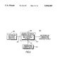
- FIG. 1 shows a prior art frequency source 10 providing a multiplied and temperature compensated frequency output 12.
- a temperature compensated frequency oscillator 14 is coupled to a temperature-independent frequency multiplier 16 which provides the desired frequency output 12.
- the frequency oscillator 14 includes a crystal oscillator 18, at least one frequency warp element 20 which is typically a varactor, a temperature compensation controller 22, a temperature sensor 24, and a memory 26.
- the memory 26 contains a preprogrammed lookup table of temperature compensating data for the crystal that correspond to predetermined temperature varying voltage signals provided by the temperature sensor 24.
- the sensor 24 is located in proximity to the crystal to reduce errors which may arise due to temperature gradients across the frequency oscillator 14.
- the sensor 24 provides a temperature indicating signal 28 to the controller 22 which directs the controller 22 to look-up the crystal compensation data in the memory 26 corresponding to the sensor signal 28.
- the controller 22 then directs a corresponding adjustment voltage signal 30 to the warp elements 20 to change their capacitance.
- the warp elements 20 are coupled to the frequency oscillator circuit 18 such that a change in capacitance will cause a corresponding change in the frequency output 32 of the frequency oscillator 14.
- the frequency oscillator 14 provides a relatively stable temperature compensated frequency output 32 to couple to the frequency multiplier 16.
- the frequency oscillator 14 may also include an external DC voltage-warp signal (not shown) to allow the adjustment of the frequency oscillator 14 to a particular output frequency 32.
- the frequency multiplier 16 is typically a frequency synthesizer incorporating a phase locked loop (PLL).
- PLL frequency synthesizers based on approaches such as fractional division or sigma-delta modulation are devices known in the art to realize temperature-independent frequency multiplication greater than one.
- frequency dividers are devices known in the art to realize temperature-independent frequency multiplication less than one.
- the frequency multiplier 16 takes the temperature compensated frequency output 32 from the frequency oscillator 14 and multiplies it to output another, usually higher, frequency 12 for use as a local oscillator in radio communications equipment.
- the disadvantage of this prior art frequency source 10 is that multiple adjustments of frequency occur in the circuit, each adjustment requiring particular additional circuitry of its own.
- the frequency oscillator 14 requires warp elements 20 to provide temperature compensation of the crystal, and the frequency source 10 requires a multiplier circuit 16 to translate the output frequency 12.
- the warp elements 20 typically include large non-linear analog varactors which require a particular crystal design that is more sensitive to capacitive load changes. Further, the more sensitive crystal design also makes the crystal more sensitive to temperature variations and aging. In addition, the temperature variations of the other components in the frequency source are not compensated.
- FIG. 2 shows another prior art frequency source 50 that utilizes a frequency oscillator 52 that is allowed to vary frequency over temperature.
- the oscillator output 54 is temperature dependent, but is subsequently compensated by a pulse deletion circuit 56 to provide temperature correction of the output 54 before being coupled to a PLL 58.
- the PLL 58 includes a first divider 60, a second divider 62, a phase detector 64, a low-pass loop filter 66, and a voltage controlled oscillator (VCO) 68.
- the source includes a temperature compensation control circuit 72 for controlling the pulse deletion circuit 56.
- the output 54 of the frequency oscillator 52 is a temperature-varying square wave pulse train which is coupled through the pulse deletion circuitry 56 to the PLL 58.
- the control circuit 72 directs the pulse deletion circuitry 56 to delete pulses from the pulse train to lower the frequency in accordance with temperature variations of the frequency oscillator 52. In this way, a relatively stable temperature compensated frequency output 76 is coupled to the PLL 58.
- the output from the pulse deletion circuitry 76 is frequency divided by the first divider 60 and input to a phase detector 64 as a reference signal.
- An output from the VCO 68 for outputting a desired frequency is divided by the second divider 62 and input into the phase detector 64.
- the phase detector 64 outputs a phase difference signal 78 through the loop filter 66 to a control terminal 80 of the VCO 68.
- the loop filter 66 reduces switching transients generated in the phase detector 64 by missing pulses in the pulse train.
- the disadvantage of this prior art frequency source 50 is that pulse deletion forces the phase detector 64 to generate a long phase difference signal 78 to the VCO 68 over any time period where a pulse is missing.
- This switching between long and short phase difference signals 78 generates sideband signals in the VCO 68 which may cause radio communication transceivers to receive or transmit on an incorrect frequency.
- a 1 ppm correction in a 15 MHz reference signal requires the deletion of 15 pulse/second from the pulse train, which causes 15 Hz phase difference signals 78 at the loop filter 66.
- the loop filter 66 needs to reject the 15 Hz signals 78 to be effective.
- a 15 Hz filter typically requires large components which is a disadvantage.
- FIG. 3 shows another prior art frequency source 100 that has very similar circuitry to the source of FIG. 2, but utilizes a direct digital synthesizer (DDS) 102 in place of the pulse deletion circuit of FIG. 2.
- the DDS 102 is clocked by the signal from the temperature-dependent frequency oscillator 104, a micro-controller 106 performs a temperature compensating bit correction, and a D-A converter in the DDS 102 converts the corrected data 108 into an temperature compensated frequency output 110.
- This source 100 has the advantage of generating a regular pulse train which reduces sideband signals, but at the expense of large current drain in the D-A converter. Further, this source 100 has the disadvantage of requiring additional frequency multiplication elements 112 in the circuit to obtain a desired multiplied output, and the temperature variations of the other components in the source are not compensated.
- FIG. 4 shows another prior art frequency source 150 that utilizes a DDS accumulator 152 to provide temperature compensation of a frequency oscillator 156 and to achieve fine frequency resolution.
- This source 150 has the disadvantage of poor spurious performance at an output 154 of the accumulator 152 due to the use of a single accumulator which takes its output from the high bit of an accumulator register. It should be recognized that accumulators are well known in the art. This approach requires significant filtering similar to that required by the pulse deletion circuit 56 of FIG. 2.
- FIG. 5 shows a general implementation of a frequency synthesizer 200 in accordance with the present invention.
- a signal 204 from an uncompensated, temperature-dependent reference frequency oscillator 202 is input to a locked loop circuit 206 which contains a temperature-dependent frequency multiplying element 208.
- the locked loop circuit 206 may be a phase locked loop, a frequency locked loop or a delay locked loop.
- a phase locked loop circuit would include a phase detector
- a frequency locked loop circuit would include a frequency detector
- a delay locked loop circuit would include a delay detector.
- the locked loop circuit 206 is a phase locked loop and the element 208 is a multi-modulus divider, preferably adjusted by a noise shaping digital modulator to permit fractional division of a frequency, allowing finer resolution than integer dividers.
- the element 208 is a dual-modulus divider and is varied, dependent upon temperature, to temperature compensate the frequency oscillator 202. This is achieved by a temperature compensation control circuit 210 which applies a temperature-dependent control signal 212 to the element 208.
- the element 208 is used, not only to temperature compensate the frequency oscillator 202, but also to multiply the oscillator frequency and provide frequency synthesis.
- the element 208 may also be used to temperature compensate all of the components of the frequency synthesizer circuit 200. This is advantageous over the prior art where temperature-dependent components are independently temperature compensated.
- the use of a single temperature compensating element 208 provides a great simplification over prior art synthesizers, in addition to the corresponding lower cost and lower current drain.
- the present invention provides another advantage in that the frequency oscillator is no longer required to provide a crystal with a particular sensitivity. This is because the crystal oscillator does not need an expansive warp range to be warped onto a nominal frequency. This frequency adjustment function can now be performed in conjunction with the multiplying function of the element 208. Therefore, a less sensitive and more robust crystal can be used which lowers cost. Also, a less sensitive crystal has better long term stability (aging). In addition, there is no longer a need for large tunable reactive elements such as varactors to warp the oscillator onto a desired frequency.
- FIG. 6 shows one embodiment of the present invention including a temperature dependent frequency oscillator 202, a locked loop circuit 206, shown as a PLL, a noise-shaping digital modulator 214, and a temperature compensation control circuit 210.
- the locked loop circuit 206 includes a phase detector 216 having an output coupled to a loop filter 218 having an output coupled to a voltage controlled oscillator 220 having an output coupled back through a multi-modulus divider 222 in a feedback path 240 of the locked loop circuit 206 to a first input of the phase detector 216.
- the frequency oscillator 202 applies a frequency to a second input of the phase detector 216 through a signal path 242.
- the oscillator provides a frequency signal through a temperature-independent second divider 224 which improves flexibility in frequency output 238 selection.
- the control circuit 210 includes a temperature sensor 226 and a memory 230 being coupled to a temperature compensation controller 228, the controller 228 of the control circuit 210 being coupled to the divider 222 and for controlling the divider 222.
- the temperature compensation control circuit 210 monitors a temperature signal 232 from a connecting temperature sensor 226 and uses the temperature signal 232 to look up a value corresponding to the temperature signal 232 in a connecting memory 230.
- the memory 230 is stored with values predetermined from previous temperature training of the synthesizer. The values have been computed to compensate for output frequency errors produced as the elements of the synthesizer circuit are subjected to varying temperature.
- the temperature compensating procedure can use a lookup table, a calculation or a combination of the two equally well for determining the appropriate temperature compensating value. As the sensor 226 indicates a change in ambient temperature, the memory 230 supplies the appropriate corresponding compensation value 234 to the temperature compensation controller 228.
- the controller 228 produces an appropriate temperature-dependent modulator control signal 212 along with a desired PLL multiplication factor to the divider 222.
- the control signal 212 is applied through a noise-shaping digital modulator 214 such that a noise reducing temperature-dependent divider modulus control signal 236 is applied to the divider 222 whereby a multiplied and temperature compensated frequency synthesizer output is achieved.
- a noise-shaping digital modulator 214 is connected in the control signal path 212 from the controller 228 to the multi-modulus divider 222 to control the divider 222 such that the PLL can achieve good frequency resolution while reducing spurious frequencies.
- the output of the noise-shaping modulator 214 is made temperature dependent by the temperature compensation control circuit 210.
- the modulator 214 increments and decrements the modulus of the multi-modulus divider 222 over a particular time period such that an averaged fractional modulus is obtained. It should be recognized that faster switching provides a better averaged modulus.
- the modulator 214 varies the frequency multiplication factor of the multi-modulus divider 222 as a function of temperature through the temperature-dependent divider modulus control 236 such that a multiplied and temperature compensated synthesizer frequency output 238 is obtained.
- the noise-shaping digital modulator 214 can be implemented in various ways.
- digital modulators in the prior art are fractional-division and sigma-delta modulators, both of which can provide adequate noise-shaping of their outputs.
- a sigma-delta modulator with a one bit output achieves fine resolution of the divider and therefore fine resolution of the synthesizer frequency output.
- These modulators serve to create an average divider modulus by varying the divider modulus in such a manner as to shape the noise created as the divider modulus is varied and translate the noise away from a nominal output frequency of the divider.
- FIG. 7 shows an alternative embodiment of the synthesizer of FIG. 6 where the temperature dependent multimodulus divider 222 is placed in the signal path 242 of the oscillator 202 and the temperature independent divider 224 is place in the feedback path 240 of the locked loop circuit 206 which is preferably a PLL. It should be recognized that any or all of the dividers in the synthesizer may be controlled with a temperature-dependent signal, but unless the system performance warrants the additional complexity this would be redundant, inefficient and not cost effective.
- FIG. 8 shows an alternative embodiment of the synthesizer of FIG. 7 where a mixer 244 is connected in the feedback path 240 and coupled to a feed forward path connecting from the oscillator signal path 242. The additional of the mixer 244 is used to increase the resolution of the locked loop circuit 206.
- FIG. 9 shows another embodiment of the present invention where a third temperature independent divider 246 is connected in a feed forward path connecting from the oscillator signal path 242, and a temperature independent divider 224 is connected in the feedback path 240 of the locked loop circuit 206 which is preferably a PLL.
- a mixer 248 is connected in the feedback path 240 and is coupled to the signal path 242 through a multi-modulus divider 222.
- the synthesizer may include more than one each of a feedback path, an oscillator signal path and a feed forward path depending on the resolution or complexity required.
- multiple independent locked loop circuits may be controlled in parallel with a control circuit, the independent locked loop signals being combined by a mixer to provide improved resolution. Any or all of these paths may incorporated a temperature dependent multi-modulus divider controlling both temperature compensation and frequency multiplication.
- FIG. 10 shows a flow diagram of a method 300 to provide a multiplied and temperature compensated synthesizer frequency output through the use of a temperature-dependent frequency multiplying element, in accordance with the present invention.
- This method 300 includes a first step 302 of providing a temperature dependent frequency oscillator and at least one frequency multiplication element in a locked loop circuit being programmed both to vary as a function of a temperature variation of the frequency oscillator and to vary as a function of a frequency multiplication factor.
- the frequency multiplication element provided is a multi-modulus divider and the locked loop circuit is a phase locked loop.
- a second step 304 includes measuring an ambient temperature in proximity to the oscillator and producing an ambient temperature value.
- a third step 306 includes searching a lookup table for a predetermined temperature dependent control signal corresponding to the ambient temperature value and the desired frequency multiplication factor. Alternatively, this step 306 may include calculating the temperature dependent control signal or a combination of searching and calculating the control signal.
- a last step 308 includes applying the control signal to the at least one frequency multiplication element such that a desired temperature compensated and multiplied output frequency is obtained from the synthesizer.
- Temperature compensation schemes often have the option of correcting for aging in the temperature-dependent frequency oscillator.
- a linear step size compensation is desirable for aging correction since the training of the temperature compensation is typically done before aging. If the step size of the compensation scheme is non-linear, the aging compensation cannot be added linearly to the temperature compensation. This situation requires the use of non-linear extrapolation circuitry to correctly compensate aging.
- the use of a noise-shaping digital modulator in the present invention provides additional linearity which is advantageous for use with aging compensation.
- the linearity advantage of using a noise-shaping digital modulator in the present invention can be shown by example, with reference to the invention of FIG. 8.
- N is a fixed integer value at a given temperature.
- F out be the multiplied and temperature-compensated output frequency and let F osc be the frequency of the temperature dependent frequency oscillator.
- the frequency change per single step in N changes at each extreme.
- the frequency change per step is: ##EQU6## which equals a resolution of 0.134 ppm.
- the present invention provides improved linear compensation performance by using a multi-modulus divider (shown as 222 in FIG. 8) controlled by a noise-shaping digital modulator, thereby reducing the complexity of aging compensation.
- the noise-shaping digital modulator used in the present invention provides a means of controlling the multi-modulus divider such that it can effectively provide a fractional, non-integer divide value such as N plus a fraction.
- the digital modulator does this by controlling the multi-modulus divider to divide by more than one value over a specified time interval. Over the specified time interval the effective divide value is a weighted average of the more than one divide values.
- the effective divide value of the divider is (N+1/100). This technique allows higher resolution with a small value of N.
- noise-shaping digital modulators have a fundamental frequency and noise sidebands about the fundamental frequency.
- Noise shaping in a digital modulator is a technique whereby the oversampled output of the digital modulator has its noise shaped in the frequency domain away from the fundamental frequency. This results in the invention having improved noise sidebands and a purer synthesized output frequency.
- the use of the noise-shaping digital modulator in the present invention reduces the complexity of aging compensation by providing a substantially linear operation of temperature compensation than is possible using only integer values for the multi-modulus divider. The substantially linear operation is described below for comparison with the foregoing integer-only operation.
- the dual-modulus divider controlled by a fractional-division noise-shaping digital modulator gives a surprising result of a differential non-linearity of about ⁇ 1% which is much improved over the differential non-linearity of about ⁇ 30% resulting from the use of a fixed integer for N.
- the integral non-linearity of the invention is unexpectedly about ⁇ 0.5% which reduces error at the extremes of the desired ⁇ 50 ppm range to about 0.25 ppm. Therefore, the dual-modulus divider has the advantage of making aging compensation possible using simple linear addition when an accuracy of better than 0.5 ppm is required.
Abstract
Description
Claims (24)
Priority Applications (6)
| Application Number | Priority Date | Filing Date | Title |
|---|---|---|---|
| US08/635,487 US5604468A (en) | 1996-04-22 | 1996-04-22 | Frequency synthesizer with temperature compensation and frequency multiplication and method of providing the same |
| CNB971929939A CN1161882C (en) | 1996-04-22 | 1997-01-31 | Frequency synthesizer with temp. compensation and frequency multiplication function and method thereof |
| EP97904231.4A EP0897616B1 (en) | 1996-04-22 | 1997-01-31 | Frequency synthesizer with temperature compensation and frequency multiplication and method of providing the same |
| KR1019980708426A KR100292965B1 (en) | 1996-04-22 | 1997-01-31 | Frequency synthesizer with temperature compensation and frequency multiplication function and method for providing same |
| JP9538033A JP2000509219A (en) | 1996-04-22 | 1997-01-31 | Frequency synthesizer having temperature compensation and frequency multiplication functions and method of manufacturing the same |
| PCT/US1997/001824 WO1997040580A1 (en) | 1996-04-22 | 1997-01-31 | Frequency synthesizer with temperature compensation and frequency multiplication and method of providing the same |
Applications Claiming Priority (1)
| Application Number | Priority Date | Filing Date | Title |
|---|---|---|---|
| US08/635,487 US5604468A (en) | 1996-04-22 | 1996-04-22 | Frequency synthesizer with temperature compensation and frequency multiplication and method of providing the same |
Publications (1)
| Publication Number | Publication Date |
|---|---|
| US5604468A true US5604468A (en) | 1997-02-18 |
Family
ID=24547989
Family Applications (1)
| Application Number | Title | Priority Date | Filing Date |
|---|---|---|---|
| US08/635,487 Expired - Lifetime US5604468A (en) | 1996-04-22 | 1996-04-22 | Frequency synthesizer with temperature compensation and frequency multiplication and method of providing the same |
Country Status (6)
| Country | Link |
|---|---|
| US (1) | US5604468A (en) |
| EP (1) | EP0897616B1 (en) |
| JP (1) | JP2000509219A (en) |
| KR (1) | KR100292965B1 (en) |
| CN (1) | CN1161882C (en) |
| WO (1) | WO1997040580A1 (en) |
Cited By (102)
| Publication number | Priority date | Publication date | Assignee | Title |
|---|---|---|---|---|
| US5781073A (en) * | 1996-07-24 | 1998-07-14 | Mii; Adam | Temperature compensation method for an output frequency drift of an oscillator |
| US5848355A (en) * | 1993-07-07 | 1998-12-08 | Motorola, Inc. | Frequency synthesizer correction using a temperature responsive divisor control |
| US5856766A (en) * | 1997-06-30 | 1999-01-05 | Motorola Inc. | Communication device with a frequency compensating synthesizer and method of providing same |
| US5883844A (en) * | 1997-05-23 | 1999-03-16 | Stmicroelectronics, Inc. | Method of stress testing integrated circuit having memory and integrated circuit having stress tester for memory thereof |
| US5973525A (en) * | 1997-10-20 | 1999-10-26 | Fujitsu Limited | Integrated circuit device |
| WO2000028665A1 (en) * | 1998-11-06 | 2000-05-18 | Dspc Technologies Ltd. | Frequency tuning for radio transceivers |
| US6154087A (en) * | 1997-10-03 | 2000-11-28 | Kabushiki Kaisha Toyoda Jidoshokki Seisakusho | Sensor output compensation circuit |
| US6255870B1 (en) | 1998-12-30 | 2001-07-03 | Hyundai Electronics Industries Co., Ltd. | Apparatus for compensating locking error in high speed memory device with delay locked loop |
| US6278867B1 (en) * | 1998-11-25 | 2001-08-21 | Ericsson Inc. | Methods and systems for frequency generation for wireless devices |
| US6282247B1 (en) * | 1997-09-12 | 2001-08-28 | Ericsson Inc. | Method and apparatus for digital compensation of radio distortion over a wide range of temperatures |
| US6321074B1 (en) * | 1999-02-18 | 2001-11-20 | Itron, Inc. | Apparatus and method for reducing oscillator frequency pulling during AM modulation |
| US20020054627A1 (en) * | 2000-11-08 | 2002-05-09 | Nokia Corporation | Synthesizer arrangement and a method for generating signals, particularly for a multimode radio telephone device |
| US6396355B1 (en) * | 2000-04-12 | 2002-05-28 | Rockwell Collins, Inc. | Signal generator having fine resolution and low phase noise |
| US20020075968A1 (en) * | 1999-10-19 | 2002-06-20 | Jared Zerbe | Method and apparatus for generating multi-level reference voltage in systems using equalization or crosstalk cancellation |
| US20020091948A1 (en) * | 1999-10-19 | 2002-07-11 | Carl Werner | Apparatus and method for improving resolution of a current mode driver |
| US6420938B1 (en) | 2000-08-30 | 2002-07-16 | Lawrence Hoff | Software controlled crystal oscillator |
| US6456164B1 (en) | 2001-03-05 | 2002-09-24 | Koninklijke Philips Electronics N.V. | Sigma delta fractional-N frequency divider with improved noise and spur performance |
| WO2002082656A2 (en) * | 2001-04-09 | 2002-10-17 | Cts Corporation | High frequency vcxo structure |
| US20020153936A1 (en) * | 1999-10-19 | 2002-10-24 | Zerbe Jared L. | Method and apparatus for receiving high speed signals with low latency |
| US20030007585A1 (en) * | 2001-06-28 | 2003-01-09 | Dalton Declan M. | Fractional-n frequency synthesizer |
| US6522871B1 (en) * | 2000-05-09 | 2003-02-18 | Qualcomm, Incorporated | Method and apparatus for compensating local oscillator frequency error through environmental control |
| US20030137361A1 (en) * | 2002-01-14 | 2003-07-24 | Thomas Knecht | Controllable crystal oscillator component |
| US20030201805A1 (en) * | 2002-04-25 | 2003-10-30 | Holland William Eric | Fractional-N baseband frequency synthesizer in bluetooth applications |
| US6690215B2 (en) * | 1999-03-17 | 2004-02-10 | Tropian, Inc. | Sigma-delta-based frequency synthesis |
| US20040119514A1 (en) * | 2002-12-23 | 2004-06-24 | Karlquist Richard K. | Systems and methods for correcting phase locked loop tracking error using feed-forward phase modulation |
| US6772351B1 (en) | 1999-10-19 | 2004-08-03 | Rambus, Inc. | Method and apparatus for calibrating a multi-level current mode driver |
| US20040179642A1 (en) * | 2003-03-13 | 2004-09-16 | Fontaine Paul A. | Low-noise sigma-delta frequency synthesizer |
| US20040196052A1 (en) * | 2001-10-24 | 2004-10-07 | Toshiyuki Okayasu | Timing generator, semiconductor test apparatus, and timing generating method |
| EP1475885A1 (en) * | 2002-01-21 | 2004-11-10 | Citizen Watch Co. Ltd. | Temperature compensation type oscillator |
| US20040222856A1 (en) * | 2003-05-02 | 2004-11-11 | Silicon Laboratories, Inc. | Calibration of oscillator devices |
| WO2004100380A1 (en) * | 2003-05-02 | 2004-11-18 | Silicon Laboratories, Inc. | Method and apparatus for a low jitter dual-loop fractional -n synthesizer |
| US20040232995A1 (en) * | 2003-05-02 | 2004-11-25 | Silicon Laboratories Inc. | Dual loop architecture useful for a programmable clock source and clock multiplier applications |
| US20040232997A1 (en) * | 2003-05-02 | 2004-11-25 | Silicon Laboratories Inc. | Method and apparatus for temperature compensation |
| US20050036580A1 (en) * | 2003-08-12 | 2005-02-17 | Rana Ram Singh | Programmable phase-locked loop fractional-N frequency synthesizer |
| US20050068118A1 (en) * | 2003-09-30 | 2005-03-31 | Silicon Laboratories, Inc. | Reconfigurable terminal |
| US20050128017A1 (en) * | 2003-12-11 | 2005-06-16 | David Meltzer | Temperature compensation for a variable frequency oscillator without reducing pull range |
| US20050128018A1 (en) * | 2003-12-11 | 2005-06-16 | David Meltzer | Temperature compensation circuit |
| US6928275B1 (en) * | 2000-05-08 | 2005-08-09 | Qualcomm Incorporated | Method and apparatus for compensating local oscillator frequency error |
| US20050212613A1 (en) * | 2004-03-26 | 2005-09-29 | Elpida Memory, Inc. | Oscillator circuit having a temperature dependence |
| US6970701B1 (en) * | 1999-11-02 | 2005-11-29 | Skyworks Solutions, Inc. | Radio calibration by correcting the crystal frequency |
| US20050285685A1 (en) * | 2004-06-28 | 2005-12-29 | Silicon Laboratories Inc. | Phase error cancellation |
| US20050285645A1 (en) * | 2004-06-28 | 2005-12-29 | Hall David R | Apparatus and method for compensating for clock drift in downhole drilling components |
| WO2006000611A1 (en) | 2004-06-24 | 2006-01-05 | Nokia Corporation | Frequency synthesizer |
| EP1619796A2 (en) * | 2004-07-20 | 2006-01-25 | Samsung Electronics Co, Ltd | Ring oscillator setting apparatus and method depending on environmental changes of an image formation apparatus |
| US20060095221A1 (en) * | 2004-11-03 | 2006-05-04 | Teradyne, Inc. | Method and apparatus for controlling variable delays in electronic circuitry |
| US20060094374A1 (en) * | 2003-03-05 | 2006-05-04 | Olip John A P | Frequency synthesizer and synthesis method for generating a multiband local oscillator signal |
| US20060113639A1 (en) * | 2002-10-15 | 2006-06-01 | Sehat Sutardja | Integrated circuit including silicon wafer with annealed glass paste |
| US20060119402A1 (en) * | 2003-05-02 | 2006-06-08 | Axel Thomsen | Multi-frequency clock synthesizer |
| US20060119437A1 (en) * | 2003-05-02 | 2006-06-08 | Axel Thomsen | Voltage controlled clock synthesizer |
| US20060255457A1 (en) * | 2002-10-15 | 2006-11-16 | Sehat Sutardja | Integrated circuit package with glass layer and oscillator |
| US20060290391A1 (en) * | 2005-06-27 | 2006-12-28 | Lsi Logic Corporation | Integrated clock generator with programmable spread spectrum using standard PLL circuitry |
| US20070058767A1 (en) * | 2005-09-09 | 2007-03-15 | Lipeng Cao | Binary stream switching controlled modulus divider for fractional frequency synthesis |
| US20070057737A1 (en) * | 2005-09-14 | 2007-03-15 | Freescale Semiconductor, Inc. | Compensation for modulation distortion |
| US20070126521A1 (en) * | 2005-11-17 | 2007-06-07 | Knecht Thomas A | Coaxial resonator based voltage controlled oscillator/phased locked loop synthesizer module |
| US20070152757A1 (en) * | 2005-12-29 | 2007-07-05 | Sridharan Kartik M | Novel method of frequency synthesis for fast switching |
| US20070164832A1 (en) * | 2006-01-17 | 2007-07-19 | Denso Corporation | Microcomputer |
| US20070176690A1 (en) * | 2002-10-15 | 2007-08-02 | Sehat Sutardja | Crystal oscillator emulator |
| US20070176705A1 (en) * | 2002-10-15 | 2007-08-02 | Sehat Sutardja | Crystal oscillator emulator |
| US20070182467A1 (en) * | 2006-02-08 | 2007-08-09 | Fujitsu Limited | DPLL circuit having holdover function |
| US20070188254A1 (en) * | 2002-10-15 | 2007-08-16 | Sehat Sutardja | Crystal oscillator emulator |
| US20070197183A1 (en) * | 2006-02-17 | 2007-08-23 | Guruswami Sridharan | Transceiver development in VHF/UHF/GSM/GPS/bluetooth/cordless telephones |
| WO2008021810A2 (en) * | 2006-08-09 | 2008-02-21 | Qualcomm Incorporated | Reference signal generation for multiple communication systems |
| US20080042765A1 (en) * | 2006-08-05 | 2008-02-21 | Min Ming Tarng | XtalClkChip: trimming-free crystal-free precision reference clock oscillator IC chip |
| US20080049822A1 (en) * | 2002-07-12 | 2008-02-28 | Rambus Inc. | Selectable-Tap Equalizer |
| US20080061899A1 (en) * | 2006-09-12 | 2008-03-13 | Stolpman James L | Apparatus and method for temperature compensation of crystal oscillators |
| US7362800B1 (en) | 2002-07-12 | 2008-04-22 | Rambus Inc. | Auto-configured equalizer |
| WO2008048644A2 (en) * | 2006-10-17 | 2008-04-24 | Marvell World Trade Ltd. | Crystal oscillator emulator |
| EP1706942A4 (en) * | 2004-01-09 | 2008-05-21 | Bosch Gmbh Robert | Frequency and/or phase compensated microelectromechanical oscillator |
| US20080248771A1 (en) * | 2002-03-06 | 2008-10-09 | Qualcomm Incorporated | Calibration techniques for frequency synthesizers |
| US20090102656A1 (en) * | 2007-09-25 | 2009-04-23 | Infinid Technologies Inc | Active ID tags for increased range and functionality |
| KR100895029B1 (en) | 2007-01-17 | 2009-04-24 | 노키아 코포레이션 | Frequency synthesizer |
| US7545228B1 (en) * | 2007-09-12 | 2009-06-09 | Sitime Inc. | Dynamic temperature compensation for a digitally controlled oscillator using dual MEMS resonators |
| EP2175558A1 (en) * | 2007-07-31 | 2010-04-14 | Panasonic Corporation | Oscillator, and receiving device and electronic device using the oscillator |
| US20100156481A1 (en) * | 2005-06-29 | 2010-06-24 | Nxp B.V. | Synchronization scheme with adaptive reference frequency correction |
| US7764131B1 (en) | 2008-09-23 | 2010-07-27 | Silicon Labs Sc, Inc. | Precision, temperature stable clock using a frequency-control circuit and dual oscillators |
| US20100225403A1 (en) * | 2009-03-05 | 2010-09-09 | Nel Frequency Controls, Inc. | Crystal- based oscillator for use in synchronized system |
| US20100277246A1 (en) * | 2008-09-23 | 2010-11-04 | Silicon Labs Sc, Inc. | Precision, temperature stable clock using a frequency-control circuit and a single oscillator |
| US20110043290A1 (en) * | 2008-05-13 | 2011-02-24 | Kazunori Hasegawa | Crystal oscillator |
| US20110068839A1 (en) * | 2009-03-05 | 2011-03-24 | Nel Frequency Controls, Inc. | System employing synchronized crystal oscillator-based clock, to be used in either discrete or integrated applications |
| US20110122973A1 (en) * | 2008-02-14 | 2011-05-26 | Panasonic Corporation | Synthesizer and receiver using the same |
| US20110187462A1 (en) * | 2010-02-01 | 2011-08-04 | Sonntag Jeffrey L | Producing a desired frequency using a controlled oscillator with known temperature sensitivity |
| US20120169399A1 (en) * | 2010-12-31 | 2012-07-05 | Stmicroelectronics (China) Investment Co. | Circuit and method for generating a clock signal |
| US20120229178A1 (en) * | 2011-03-08 | 2012-09-13 | Rfdot Microelectronics Inc. | Method and apparatus for calibrating frequency |
| TWI424680B (en) * | 2006-10-17 | 2014-01-21 | Marvell World Trade Ltd | Crystal oscillator emulator |
| US8861667B1 (en) | 2002-07-12 | 2014-10-14 | Rambus Inc. | Clock data recovery circuit with equalizer clock calibration |
| US20150077189A1 (en) * | 2013-09-18 | 2015-03-19 | Nihon Dempa Kogyo Co. Ltd. | Oscillator |
| TWI485986B (en) * | 2010-08-23 | 2015-05-21 | Realtek Semiconductor Corp | Method and apparatus for clock signal synthesis |
| WO2015074133A1 (en) | 2013-11-25 | 2015-05-28 | Nanowave Technologies Inc. | Digitally compensated phase locked oscillator |
| NL2011982C2 (en) * | 2013-12-18 | 2015-06-22 | Frapinv S B V | System and method for operating a mechanical resonator in an electronic oscillator. |
| US20150341041A1 (en) * | 2014-05-21 | 2015-11-26 | Robert Bosch Gmbh | Phase Lock Loop Circuit Having a Wide Bandwidth |
| CN105242541A (en) * | 2015-10-27 | 2016-01-13 | 上海航天精密机械研究所 | Temperature compensation control method for response delay process |
| CN105322960A (en) * | 2014-07-23 | 2016-02-10 | 硅实验室股份有限公司 | Clock generator using free-running oscillator and method therefor |
| US20160099716A1 (en) * | 2014-10-01 | 2016-04-07 | Fujitsu Limited | Control device for clock generation circuit, control method for clock generation circuit, and clock generation circuit |
| US9548744B2 (en) | 2014-08-18 | 2017-01-17 | Qualcomm Incorporated | Compensating for hysteretic characteristics of crystal oscillators |
| US10312924B2 (en) * | 2015-12-21 | 2019-06-04 | Seiko Epson Corporation | Timing signal generation device, electronic device, and moving object |
| WO2019106157A1 (en) | 2017-12-01 | 2019-06-06 | Novo Nordisk A/S | Crystal-free oscillator for channel-based high-frequency radio communication |
| US10396747B2 (en) | 2016-06-07 | 2019-08-27 | Seiko Epson Corporation | Temperature compensated oscillation circuit, oscillator, electronic apparatus, vehicle, and method of manufacturing oscillator |
| CN110289857A (en) * | 2019-05-20 | 2019-09-27 | 昇显微电子(苏州)有限公司 | A kind of clock forming circuit |
| WO2019236319A1 (en) * | 2018-06-06 | 2019-12-12 | Microchip Technology Incorporated | Compensating for frequency variation of a crystal oscillator and related systems, methods and devices |
| US10623006B2 (en) | 2017-06-28 | 2020-04-14 | Analog Devices, Inc. | Apparatus and methods for compensation of signal path delay variation |
| US11038511B2 (en) | 2017-06-28 | 2021-06-15 | Analog Devices International Unlimited Company | Apparatus and methods for system clock compensation |
| US20210311448A1 (en) * | 2018-06-26 | 2021-10-07 | Mks Instruments, Inc. | Adaptive Control For A Power Generator |
Families Citing this family (22)
| Publication number | Priority date | Publication date | Assignee | Title |
|---|---|---|---|---|
| EP1168634B1 (en) * | 2000-06-28 | 2007-06-13 | STMicroelectronics N.V. | Method for reducing the electricity consumption of a mobile cellular telephone |
| CN100547905C (en) * | 2005-11-17 | 2009-10-07 | 中国科学院半导体研究所 | Circulation circuit voltage-controlled oscillator with temperature compensation effect |
| JP2007243586A (en) * | 2006-03-08 | 2007-09-20 | Oki Electric Ind Co Ltd | Circuit and method for correcting clock, mobile body terminal, and base station device |
| KR100861966B1 (en) * | 2007-02-02 | 2008-10-07 | 엘아이지넥스원 주식회사 | Apparatus for stability of yig osc in pll |
| GB2455717A (en) * | 2007-12-17 | 2009-06-24 | Ubiquisys Ltd | Frequency synthesis in a wireless basestation |
| JP4835596B2 (en) * | 2008-01-10 | 2011-12-14 | パナソニック株式会社 | Synthesizer or oscillator module, and synthesizer module, receiver, and electronic device using the synthesizer |
| CN101272142B (en) * | 2008-05-20 | 2011-05-18 | 曹秀娟 | Frequency synthesizer |
| WO2010023883A1 (en) * | 2008-08-28 | 2010-03-04 | パナソニック株式会社 | Synthesizer and reception device and electronic device using the same |
| JP5424473B2 (en) * | 2009-08-31 | 2014-02-26 | 京セラクリスタルデバイス株式会社 | Oscillator circuit |
| JP5426316B2 (en) * | 2009-10-21 | 2014-02-26 | 日本電波工業株式会社 | Frequency synthesizer |
| DE102010041999A1 (en) * | 2010-10-05 | 2012-04-05 | Robert Bosch Gmbh | Method for correcting actual position of sensor parameter e.g. charge pressure sensor, for detecting pressure of gaseous or liquid medium in air system of motor car, involves correcting parameter by pressurizing with compensation parameter |
| JP6092540B2 (en) * | 2011-08-01 | 2017-03-08 | 日本電波工業株式会社 | Crystal oscillator |
| CN102508199A (en) * | 2011-11-12 | 2012-06-20 | 太原理工大学 | Positioning method based on radio phase discriminating technology |
| JP5872493B2 (en) * | 2012-06-13 | 2016-03-01 | 株式会社東芝 | Oscillation frequency adjustment circuit |
| CN103916150B (en) * | 2013-01-07 | 2016-09-14 | 深圳市锐迪芯电子有限公司 | A kind of wireless receiver of non-crystal oscillator |
| US9281823B2 (en) * | 2013-02-20 | 2016-03-08 | Si-Ware Systems | Single insertion trimming of highly accurate reference oscillators |
| RU2523188C1 (en) * | 2013-04-09 | 2014-07-20 | Закрытое акционерное общество "Научно-производственная фирма "Микран" | Frequency synthesiser |
| JP2016063392A (en) * | 2014-09-18 | 2016-04-25 | セイコーエプソン株式会社 | Reference signal generator |
| JP6561568B2 (en) * | 2015-05-08 | 2019-08-21 | セイコーエプソン株式会社 | Wireless transmission device |
| CN105471455B (en) * | 2015-11-11 | 2018-10-12 | 中国电子科技集团公司第四十一研究所 | The compensation method of signal receiving channel frequency response under the conditions of a kind of width is warm |
| CN106774630B (en) * | 2017-01-18 | 2019-07-26 | 西华大学 | A kind of compensation Direct Digital Frequency Synthesizers |
| JP7124417B2 (en) * | 2018-04-24 | 2022-08-24 | セイコーエプソン株式会社 | Circuit devices, oscillators, electronic devices and moving bodies |
Citations (7)
| Publication number | Priority date | Publication date | Assignee | Title |
|---|---|---|---|---|
| US4454483A (en) * | 1982-03-25 | 1984-06-12 | Cubic Corporation | Temperature compensation of an oscillator by fractional cycle synthesis |
| US4644297A (en) * | 1986-03-03 | 1987-02-17 | Motorola, Inc. | Frequency locked loop for the temperature compensation of phase coded surface acoustic wave devices |
| US5126699A (en) * | 1991-09-27 | 1992-06-30 | Allied-Signal Inc. | Digitally compensated modulation system for frequency synthesizers |
| US5216389A (en) * | 1992-01-31 | 1993-06-01 | Motorola, Inc. | Temperature compensation of a crystal reference using direct digital synthesis |
| US5355098A (en) * | 1992-04-24 | 1994-10-11 | Ricoh Company, Ltd. | Phase-locked loop with memory storing control data controlling the oscillation frequency |
| US5477194A (en) * | 1993-07-12 | 1995-12-19 | Nec Corporation | Temperature compensated PLL frequency synthesizer and high-speed frequency lock method using the same |
| US5485127A (en) * | 1993-12-29 | 1996-01-16 | Intel Corporation | Integrated dynamic power dissipation control system for very large scale integrated (VLSI) chips |
Family Cites Families (2)
| Publication number | Priority date | Publication date | Assignee | Title |
|---|---|---|---|---|
| GB2024546B (en) * | 1978-05-26 | 1982-12-22 | Racal Group Services Ltd | Frequency synthesisers |
| JPS6335017A (en) * | 1986-07-30 | 1988-02-15 | Japan Radio Co Ltd | Radio frequency stabilizing device |
-
1996
- 1996-04-22 US US08/635,487 patent/US5604468A/en not_active Expired - Lifetime
-
1997
- 1997-01-31 WO PCT/US1997/001824 patent/WO1997040580A1/en active IP Right Grant
- 1997-01-31 EP EP97904231.4A patent/EP0897616B1/en not_active Expired - Lifetime
- 1997-01-31 KR KR1019980708426A patent/KR100292965B1/en not_active IP Right Cessation
- 1997-01-31 CN CNB971929939A patent/CN1161882C/en not_active Expired - Fee Related
- 1997-01-31 JP JP9538033A patent/JP2000509219A/en not_active Ceased
Patent Citations (7)
| Publication number | Priority date | Publication date | Assignee | Title |
|---|---|---|---|---|
| US4454483A (en) * | 1982-03-25 | 1984-06-12 | Cubic Corporation | Temperature compensation of an oscillator by fractional cycle synthesis |
| US4644297A (en) * | 1986-03-03 | 1987-02-17 | Motorola, Inc. | Frequency locked loop for the temperature compensation of phase coded surface acoustic wave devices |
| US5126699A (en) * | 1991-09-27 | 1992-06-30 | Allied-Signal Inc. | Digitally compensated modulation system for frequency synthesizers |
| US5216389A (en) * | 1992-01-31 | 1993-06-01 | Motorola, Inc. | Temperature compensation of a crystal reference using direct digital synthesis |
| US5355098A (en) * | 1992-04-24 | 1994-10-11 | Ricoh Company, Ltd. | Phase-locked loop with memory storing control data controlling the oscillation frequency |
| US5477194A (en) * | 1993-07-12 | 1995-12-19 | Nec Corporation | Temperature compensated PLL frequency synthesizer and high-speed frequency lock method using the same |
| US5485127A (en) * | 1993-12-29 | 1996-01-16 | Intel Corporation | Integrated dynamic power dissipation control system for very large scale integrated (VLSI) chips |
Non-Patent Citations (2)
| Title |
|---|
| "Performance Tests on an MCXO Combining ASIC and Hybrid Construction," 45th Annual Symposium on Frequency Control, 1991, IEEE. Benjaminson et al. Issued 1991 pp. 393-397. |
| Performance Tests on an MCXO Combining ASIC and Hybrid Construction, 45th Annual Symposium on Frequency Control, 1991, IEEE. Benjaminson et al. Issued 1991 pp. 393 397. * |
Cited By (228)
| Publication number | Priority date | Publication date | Assignee | Title |
|---|---|---|---|---|
| US5848355A (en) * | 1993-07-07 | 1998-12-08 | Motorola, Inc. | Frequency synthesizer correction using a temperature responsive divisor control |
| US5781073A (en) * | 1996-07-24 | 1998-07-14 | Mii; Adam | Temperature compensation method for an output frequency drift of an oscillator |
| US5883844A (en) * | 1997-05-23 | 1999-03-16 | Stmicroelectronics, Inc. | Method of stress testing integrated circuit having memory and integrated circuit having stress tester for memory thereof |
| US5856766A (en) * | 1997-06-30 | 1999-01-05 | Motorola Inc. | Communication device with a frequency compensating synthesizer and method of providing same |
| US6282247B1 (en) * | 1997-09-12 | 2001-08-28 | Ericsson Inc. | Method and apparatus for digital compensation of radio distortion over a wide range of temperatures |
| US6154087A (en) * | 1997-10-03 | 2000-11-28 | Kabushiki Kaisha Toyoda Jidoshokki Seisakusho | Sensor output compensation circuit |
| US5973525A (en) * | 1997-10-20 | 1999-10-26 | Fujitsu Limited | Integrated circuit device |
| US7113751B2 (en) | 1998-11-06 | 2006-09-26 | Intel Corporation | Frequency tuning of radio transceivers |
| WO2000028665A1 (en) * | 1998-11-06 | 2000-05-18 | Dspc Technologies Ltd. | Frequency tuning for radio transceivers |
| US20020127984A1 (en) * | 1998-11-06 | 2002-09-12 | Ilan Barak | Frequency tuning of radio transceivers |
| US6400930B1 (en) | 1998-11-06 | 2002-06-04 | Dspc Israel, Ltd. | Frequency tuning for radio transceivers |
| ES2187305A1 (en) * | 1998-11-06 | 2003-05-16 | Dspc Tech Ltd | Frequency tuning for radio transceivers |
| US6278867B1 (en) * | 1998-11-25 | 2001-08-21 | Ericsson Inc. | Methods and systems for frequency generation for wireless devices |
| US6255870B1 (en) | 1998-12-30 | 2001-07-03 | Hyundai Electronics Industries Co., Ltd. | Apparatus for compensating locking error in high speed memory device with delay locked loop |
| US6321074B1 (en) * | 1999-02-18 | 2001-11-20 | Itron, Inc. | Apparatus and method for reducing oscillator frequency pulling during AM modulation |
| US6690215B2 (en) * | 1999-03-17 | 2004-02-10 | Tropian, Inc. | Sigma-delta-based frequency synthesis |
| US8320494B2 (en) | 1999-10-19 | 2012-11-27 | Rambus Inc. | Method and apparatus for generating reference voltage to adjust for attenuation |
| US7859436B2 (en) | 1999-10-19 | 2010-12-28 | Rambus Inc. | Memory device receiver |
| US20020091948A1 (en) * | 1999-10-19 | 2002-07-11 | Carl Werner | Apparatus and method for improving resolution of a current mode driver |
| US9998305B2 (en) | 1999-10-19 | 2018-06-12 | Rambus Inc. | Multi-PAM output driver with distortion compensation |
| US20060061405A1 (en) * | 1999-10-19 | 2006-03-23 | Zerbe Jared L | Method and apparatus for receiving high speed signals with low latency |
| US20020153936A1 (en) * | 1999-10-19 | 2002-10-24 | Zerbe Jared L. | Method and apparatus for receiving high speed signals with low latency |
| US9544169B2 (en) | 1999-10-19 | 2017-01-10 | Rambus Inc. | Multiphase receiver with equalization circuitry |
| US7072415B2 (en) | 1999-10-19 | 2006-07-04 | Rambus Inc. | Method and apparatus for generating multi-level reference voltage in systems using equalization or crosstalk cancellation |
| US20020075968A1 (en) * | 1999-10-19 | 2002-06-20 | Jared Zerbe | Method and apparatus for generating multi-level reference voltage in systems using equalization or crosstalk cancellation |
| US7626442B2 (en) | 1999-10-19 | 2009-12-01 | Rambus Inc. | Low latency multi-level communication interface |
| US20100134153A1 (en) * | 1999-10-19 | 2010-06-03 | Zerbe Jared L | Low Latency Multi-Level Communication Interface |
| US20060186915A1 (en) * | 1999-10-19 | 2006-08-24 | Carl Werner | Method and apparatus for calibrating a multi-level current mode driver having a plurality of source calibration signals |
| US7124221B1 (en) | 1999-10-19 | 2006-10-17 | Rambus Inc. | Low latency multi-level communication interface |
| US20090097338A1 (en) * | 1999-10-19 | 2009-04-16 | Carl Werner | Memory Device Receiver |
| US6772351B1 (en) | 1999-10-19 | 2004-08-03 | Rambus, Inc. | Method and apparatus for calibrating a multi-level current mode driver |
| US7809088B2 (en) | 1999-10-19 | 2010-10-05 | Rambus Inc. | Multiphase receiver with equalization |
| US20060233278A1 (en) * | 1999-10-19 | 2006-10-19 | Rambus Inc. | Method and apparatus for generating multi-level reference voltage in systems using equalization or crosstalk cancellation |
| US7126408B2 (en) | 1999-10-19 | 2006-10-24 | Rambus Inc. | Method and apparatus for receiving high-speed signals with low latency |
| US20110140741A1 (en) * | 1999-10-19 | 2011-06-16 | Zerbe Jared L | Integrating receiver with precharge circuitry |
| US8199859B2 (en) | 1999-10-19 | 2012-06-12 | Rambus Inc. | Integrating receiver with precharge circuitry |
| US6965262B2 (en) | 1999-10-19 | 2005-11-15 | Rambus Inc. | Method and apparatus for receiving high speed signals with low latency |
| US8634452B2 (en) | 1999-10-19 | 2014-01-21 | Rambus Inc. | Multiphase receiver with equalization circuitry |
| US7161513B2 (en) * | 1999-10-19 | 2007-01-09 | Rambus Inc. | Apparatus and method for improving resolution of a current mode driver |
| US6970701B1 (en) * | 1999-11-02 | 2005-11-29 | Skyworks Solutions, Inc. | Radio calibration by correcting the crystal frequency |
| US6396355B1 (en) * | 2000-04-12 | 2002-05-28 | Rockwell Collins, Inc. | Signal generator having fine resolution and low phase noise |
| US6928275B1 (en) * | 2000-05-08 | 2005-08-09 | Qualcomm Incorporated | Method and apparatus for compensating local oscillator frequency error |
| US6522871B1 (en) * | 2000-05-09 | 2003-02-18 | Qualcomm, Incorporated | Method and apparatus for compensating local oscillator frequency error through environmental control |
| US6420938B1 (en) | 2000-08-30 | 2002-07-16 | Lawrence Hoff | Software controlled crystal oscillator |
| EP1206039A3 (en) * | 2000-11-08 | 2004-09-29 | Nokia Corporation | A synthesizer arrangement and a method for generating signals, particularly for a multimode radio telephone device |
| EP1206039A2 (en) * | 2000-11-08 | 2002-05-15 | Nokia Corporation | A synthesizer arrangement and a method for generating signals, particularly for a multimode radio telephone device |
| US20020054627A1 (en) * | 2000-11-08 | 2002-05-09 | Nokia Corporation | Synthesizer arrangement and a method for generating signals, particularly for a multimode radio telephone device |
| US6456164B1 (en) | 2001-03-05 | 2002-09-24 | Koninklijke Philips Electronics N.V. | Sigma delta fractional-N frequency divider with improved noise and spur performance |
| WO2002082656A3 (en) * | 2001-04-09 | 2004-02-19 | Cts Corp | High frequency vcxo structure |
| WO2002082656A2 (en) * | 2001-04-09 | 2002-10-17 | Cts Corporation | High frequency vcxo structure |
| US20030007585A1 (en) * | 2001-06-28 | 2003-01-09 | Dalton Declan M. | Fractional-n frequency synthesizer |
| US20040196052A1 (en) * | 2001-10-24 | 2004-10-07 | Toshiyuki Okayasu | Timing generator, semiconductor test apparatus, and timing generating method |
| KR100943938B1 (en) | 2001-10-24 | 2010-02-24 | 주식회사 아도반테스토 | Timing Generator, Semiconductor Testing Device, and Timing Generating Method |
| US6940330B2 (en) * | 2001-10-24 | 2005-09-06 | Advantest Corporation | Timing generator, semiconductor test apparatus, and timing generating method |
| US20030137361A1 (en) * | 2002-01-14 | 2003-07-24 | Thomas Knecht | Controllable crystal oscillator component |
| US6946919B2 (en) | 2002-01-14 | 2005-09-20 | Cts Corporation | Controllable crystal oscillator component |
| US7583157B2 (en) | 2002-01-21 | 2009-09-01 | Citizen Holdings Co., Ltd. | Method of manufacturing a temperature compensated oscillator |
| CN100492879C (en) * | 2002-01-21 | 2009-05-27 | 西铁城控股株式会社 | Temperature compensation type oscillator |
| US20050040904A1 (en) * | 2002-01-21 | 2005-02-24 | Yasuhiro Sakurai | Temperature compensation type oscillator |
| EP1475885A4 (en) * | 2002-01-21 | 2005-04-20 | Citizen Watch Co Ltd | Temperature compensation type oscillator |
| US20070030084A1 (en) * | 2002-01-21 | 2007-02-08 | Citizen Watch Co., Ltd. | Method of manufacturing a temperature compensated oscillator |
| EP1475885A1 (en) * | 2002-01-21 | 2004-11-10 | Citizen Watch Co. Ltd. | Temperature compensation type oscillator |
| US8019301B2 (en) * | 2002-03-06 | 2011-09-13 | Qualcomm Incorporated | Calibration techniques for frequency synthesizers |
| US20080248771A1 (en) * | 2002-03-06 | 2008-10-09 | Qualcomm Incorporated | Calibration techniques for frequency synthesizers |
| US7471123B2 (en) | 2002-04-25 | 2008-12-30 | Agere Systems Inc. | Fractional-N baseband frequency synthesizer in bluetooth applications |
| US20030201805A1 (en) * | 2002-04-25 | 2003-10-30 | Holland William Eric | Fractional-N baseband frequency synthesizer in bluetooth applications |
| US6946884B2 (en) * | 2002-04-25 | 2005-09-20 | Agere Systems Inc. | Fractional-N baseband frequency synthesizer in bluetooth applications |
| US8861667B1 (en) | 2002-07-12 | 2014-10-14 | Rambus Inc. | Clock data recovery circuit with equalizer clock calibration |
| US20080049822A1 (en) * | 2002-07-12 | 2008-02-28 | Rambus Inc. | Selectable-Tap Equalizer |
| US7362800B1 (en) | 2002-07-12 | 2008-04-22 | Rambus Inc. | Auto-configured equalizer |
| US7760036B2 (en) | 2002-10-15 | 2010-07-20 | Marvell World Trade Ltd. | Crystal oscillator emulator |
| US9143083B2 (en) | 2002-10-15 | 2015-09-22 | Marvell World Trade Ltd. | Crystal oscillator emulator with externally selectable operating configurations |
| US20060255457A1 (en) * | 2002-10-15 | 2006-11-16 | Sehat Sutardja | Integrated circuit package with glass layer and oscillator |
| US20060262623A1 (en) * | 2002-10-15 | 2006-11-23 | Sehat Sutardja | Phase locked loop with temperature compensation |
| US20060267194A1 (en) * | 2002-10-15 | 2006-11-30 | Sehat Sutardja | Integrated circuit package with air gap |
| US7786817B2 (en) | 2002-10-15 | 2010-08-31 | Marvell World Trade Ltd. | Crystal oscillator emulator |
| US9350360B2 (en) | 2002-10-15 | 2016-05-24 | Marvell World Trade Ltd. | Systems and methods for configuring a semiconductor device |
| US7791424B2 (en) * | 2002-10-15 | 2010-09-07 | Marvell World Trade Ltd. | Crystal oscillator emulator |
| US20070188253A1 (en) * | 2002-10-15 | 2007-08-16 | Sehat Sutardja | Crystal oscillator emulator |
| US20070188254A1 (en) * | 2002-10-15 | 2007-08-16 | Sehat Sutardja | Crystal oscillator emulator |
| US7768361B2 (en) | 2002-10-15 | 2010-08-03 | Marvell World Trade Ltd. | Crystal oscillator emulator |
| US7812683B2 (en) | 2002-10-15 | 2010-10-12 | Marvell World Trade Ltd. | Integrated circuit package with glass layer and oscillator |
| US20070182500A1 (en) * | 2002-10-15 | 2007-08-09 | Sehat Sutardja | Crystal oscillator emulator |
| US20060113639A1 (en) * | 2002-10-15 | 2006-06-01 | Sehat Sutardja | Integrated circuit including silicon wafer with annealed glass paste |
| US7768360B2 (en) | 2002-10-15 | 2010-08-03 | Marvell World Trade Ltd. | Crystal oscillator emulator |
| US8063711B2 (en) | 2002-10-15 | 2011-11-22 | Marvell World Trade Ltd. | Crystal oscillator emulator |
| US7760039B2 (en) | 2002-10-15 | 2010-07-20 | Marvell World Trade Ltd. | Crystal oscillator emulator |
| US20110001571A1 (en) * | 2002-10-15 | 2011-01-06 | Sehat Sutardja | Crystal oscillator emulator |
| US20080042767A1 (en) * | 2002-10-15 | 2008-02-21 | Sehat Sutardja | Crystal oscillator emulator |
| US20070176690A1 (en) * | 2002-10-15 | 2007-08-02 | Sehat Sutardja | Crystal oscillator emulator |
| US20070176705A1 (en) * | 2002-10-15 | 2007-08-02 | Sehat Sutardja | Crystal oscillator emulator |
| US6831491B2 (en) * | 2002-12-23 | 2004-12-14 | Agilent Technologies, Inc. | Systems and methods for correcting phase locked loop tracking error using feed-forward phase modulation |
| US20040119514A1 (en) * | 2002-12-23 | 2004-06-24 | Karlquist Richard K. | Systems and methods for correcting phase locked loop tracking error using feed-forward phase modulation |
| US20060094374A1 (en) * | 2003-03-05 | 2006-05-04 | Olip John A P | Frequency synthesizer and synthesis method for generating a multiband local oscillator signal |
| US7515931B2 (en) * | 2003-03-05 | 2009-04-07 | Cisco Technology, Inc. | Frequency synthesizer and synthesis method for generating a multiband local oscillator signal |
| US20040179642A1 (en) * | 2003-03-13 | 2004-09-16 | Fontaine Paul A. | Low-noise sigma-delta frequency synthesizer |
| US7315601B2 (en) * | 2003-03-13 | 2008-01-01 | Texas Instruments Incorporated | Low-noise sigma-delta frequency synthesizer |
| WO2004100380A1 (en) * | 2003-05-02 | 2004-11-18 | Silicon Laboratories, Inc. | Method and apparatus for a low jitter dual-loop fractional -n synthesizer |
| US7825708B2 (en) | 2003-05-02 | 2010-11-02 | Silicon Laboratories Inc. | Dual loop architecture useful for a programmable clock source and clock multiplier applications |
| US7288998B2 (en) | 2003-05-02 | 2007-10-30 | Silicon Laboratories Inc. | Voltage controlled clock synthesizer |
| US20040222856A1 (en) * | 2003-05-02 | 2004-11-11 | Silicon Laboratories, Inc. | Calibration of oscillator devices |
| US20090039968A1 (en) * | 2003-05-02 | 2009-02-12 | Axel Thomsen | Dual loop architecture useful for a programmable clock source and clock multiplier applications |
| US20060119437A1 (en) * | 2003-05-02 | 2006-06-08 | Axel Thomsen | Voltage controlled clock synthesizer |
| US20040232997A1 (en) * | 2003-05-02 | 2004-11-25 | Silicon Laboratories Inc. | Method and apparatus for temperature compensation |
| CN1784831B (en) * | 2003-05-02 | 2013-07-17 | 硅谷实验室公司 | Method and apparatus for a low jitter dual-loop fractional N-type synthesizer |
| US20040232995A1 (en) * | 2003-05-02 | 2004-11-25 | Silicon Laboratories Inc. | Dual loop architecture useful for a programmable clock source and clock multiplier applications |
| US20070146083A1 (en) * | 2003-05-02 | 2007-06-28 | Jerrell Hein | Calibration of oscillator devices |
| US7295077B2 (en) | 2003-05-02 | 2007-11-13 | Silicon Laboratories Inc. | Multi-frequency clock synthesizer |
| US7436227B2 (en) | 2003-05-02 | 2008-10-14 | Silicon Laboratories Inc. | Dual loop architecture useful for a programmable clock source and clock multiplier applications |
| US7187241B2 (en) | 2003-05-02 | 2007-03-06 | Silicon Laboratories Inc. | Calibration of oscillator devices |
| US7064617B2 (en) | 2003-05-02 | 2006-06-20 | Silicon Laboratories Inc. | Method and apparatus for temperature compensation |
| US20060119402A1 (en) * | 2003-05-02 | 2006-06-08 | Axel Thomsen | Multi-frequency clock synthesizer |
| US20050036580A1 (en) * | 2003-08-12 | 2005-02-17 | Rana Ram Singh | Programmable phase-locked loop fractional-N frequency synthesizer |
| US20050068118A1 (en) * | 2003-09-30 | 2005-03-31 | Silicon Laboratories, Inc. | Reconfigurable terminal |
| US7167058B2 (en) | 2003-12-11 | 2007-01-23 | Seiko Epson Corporation | Temperature compensation for a variable frequency oscillator without reducing pull range |
| US7161440B2 (en) | 2003-12-11 | 2007-01-09 | Seiko Epson Corporation | Temperature compensation circuit |
| US20050128018A1 (en) * | 2003-12-11 | 2005-06-16 | David Meltzer | Temperature compensation circuit |
| US20050128017A1 (en) * | 2003-12-11 | 2005-06-16 | David Meltzer | Temperature compensation for a variable frequency oscillator without reducing pull range |
| US20080164953A1 (en) * | 2004-01-09 | 2008-07-10 | Aaron Partridge | Frequency and/or phase compensated microelectromechanical oscillator |
| US7532081B2 (en) | 2004-01-09 | 2009-05-12 | Robert Bosch Gmbh | Frequency and/or phase compensated microelectromechanical oscillator |
| US7907027B2 (en) | 2004-01-09 | 2011-03-15 | Robert Bosch Gmbh | Frequency and/or phase compensated microelectromechanical oscillator |
| US7453324B2 (en) | 2004-01-09 | 2008-11-18 | Robert Bosch Gmbh | Frequency and/or phase compensated microelectromechanical oscillator |
| EP3002878A1 (en) * | 2004-01-09 | 2016-04-06 | Robert Bosch Gmbh | Frequency and/or phase compensated microelectromechanical oscillator |
| US20090278619A1 (en) * | 2004-01-09 | 2009-11-12 | Aaron Partridge | Frequency and/or phase compensated microelectromechanical oscillator |
| EP1706942A4 (en) * | 2004-01-09 | 2008-05-21 | Bosch Gmbh Robert | Frequency and/or phase compensated microelectromechanical oscillator |
| US7209015B2 (en) * | 2004-03-26 | 2007-04-24 | Elpida Memory, Inc. | Oscillator circuit having a temperature dependence |
| US20050212613A1 (en) * | 2004-03-26 | 2005-09-29 | Elpida Memory, Inc. | Oscillator circuit having a temperature dependence |
| US7145402B2 (en) | 2004-06-24 | 2006-12-05 | Nokia Corporation | Multi-mode frequency synthesizer with temperature compensation |
| WO2006000611A1 (en) | 2004-06-24 | 2006-01-05 | Nokia Corporation | Frequency synthesizer |
| US7068110B2 (en) | 2004-06-28 | 2006-06-27 | Silicon Laboratories Inc. | Phase error cancellation |
| US20080211588A1 (en) * | 2004-06-28 | 2008-09-04 | Frey Douglas R | Phase Error Cancellation |
| US7834706B2 (en) | 2004-06-28 | 2010-11-16 | Silicon Laboratories Inc. | Phase error cancellation |
| US7253671B2 (en) * | 2004-06-28 | 2007-08-07 | Intelliserv, Inc. | Apparatus and method for compensating for clock drift in downhole drilling components |
| US20050285645A1 (en) * | 2004-06-28 | 2005-12-29 | Hall David R | Apparatus and method for compensating for clock drift in downhole drilling components |
| US20050285685A1 (en) * | 2004-06-28 | 2005-12-29 | Silicon Laboratories Inc. | Phase error cancellation |
| EP1619796A2 (en) * | 2004-07-20 | 2006-01-25 | Samsung Electronics Co, Ltd | Ring oscillator setting apparatus and method depending on environmental changes of an image formation apparatus |
| US7307482B2 (en) * | 2004-07-20 | 2007-12-11 | Samsung Electronics Co., Ltd. | Ring oscillator setting apparatus and method depending on environmental changes of an image formation apparatus |
| EP1619796A3 (en) * | 2004-07-20 | 2008-12-03 | Samsung Electronics Co, Ltd | Ring oscillator setting apparatus and method depending on environmental changes of an image formation apparatus |
| US20060017514A1 (en) * | 2004-07-20 | 2006-01-26 | Samsung Electronics Co., Ltd. | Ring oscillator setting apparatus and method depending on environmental changes of an image formation apparatus |
| US20060095221A1 (en) * | 2004-11-03 | 2006-05-04 | Teradyne, Inc. | Method and apparatus for controlling variable delays in electronic circuitry |
| US7327172B2 (en) * | 2005-06-27 | 2008-02-05 | Lsi Corporation | Integrated clock generator with programmable spread spectrum using standard PLL circuitry |
| US20060290391A1 (en) * | 2005-06-27 | 2006-12-28 | Lsi Logic Corporation | Integrated clock generator with programmable spread spectrum using standard PLL circuitry |
| US8004322B2 (en) * | 2005-06-29 | 2011-08-23 | St-Ericsson Sa | Synchronization scheme with adaptive reference frequency correction |
| US20100156481A1 (en) * | 2005-06-29 | 2010-06-24 | Nxp B.V. | Synchronization scheme with adaptive reference frequency correction |
| US8400195B2 (en) | 2005-06-29 | 2013-03-19 | St-Ericsson Sa | Synchronization scheme with adaptive reference frequency correction |
| US7539277B2 (en) * | 2005-09-09 | 2009-05-26 | Freescale Semiconductor, Inc. | Binary stream switching controlled modulus divider for fractional frequency synthesis |
| US20070058767A1 (en) * | 2005-09-09 | 2007-03-15 | Lipeng Cao | Binary stream switching controlled modulus divider for fractional frequency synthesis |
| US20070057737A1 (en) * | 2005-09-14 | 2007-03-15 | Freescale Semiconductor, Inc. | Compensation for modulation distortion |
| US7541883B2 (en) | 2005-11-17 | 2009-06-02 | Cts Corporation | Coaxial resonator based voltage controlled oscillator/phased locked loop synthesizer module |
| US20070126521A1 (en) * | 2005-11-17 | 2007-06-07 | Knecht Thomas A | Coaxial resonator based voltage controlled oscillator/phased locked loop synthesizer module |
| US7898345B2 (en) | 2005-12-29 | 2011-03-01 | Orca Systems, Inc. | Method of frequency synthesis for fast switching |
| US20090146747A1 (en) * | 2005-12-29 | 2009-06-11 | Sridharan Kartik M | Novel method of frequency synthesis for fast switching |
| US20070152757A1 (en) * | 2005-12-29 | 2007-07-05 | Sridharan Kartik M | Novel method of frequency synthesis for fast switching |
| US7482885B2 (en) | 2005-12-29 | 2009-01-27 | Orca Systems, Inc. | Method of frequency synthesis for fast switching |
| US20070164832A1 (en) * | 2006-01-17 | 2007-07-19 | Denso Corporation | Microcomputer |
| US7554415B2 (en) | 2006-01-17 | 2009-06-30 | Denso Corporation | Microcomputer including a CR oscillator circuit |
| US20070182467A1 (en) * | 2006-02-08 | 2007-08-09 | Fujitsu Limited | DPLL circuit having holdover function |
| US7330057B2 (en) * | 2006-02-08 | 2008-02-12 | Fujitsu Limited | DPLL circuit having holdover function |
| US7519349B2 (en) | 2006-02-17 | 2009-04-14 | Orca Systems, Inc. | Transceiver development in VHF/UHF/GSM/GPS/bluetooth/cordless telephones |
| US7979046B2 (en) | 2006-02-17 | 2011-07-12 | Orca Systems, Inc. | Transceiver development in VHF/UHF/GSM/GPS/bluetooth/cordless telephones |
| US20090147884A1 (en) * | 2006-02-17 | 2009-06-11 | Guruswami Sridharan | Transceiver development in vhf/uhf/gsm/gps/bluetooth/cordless telephones |
| US20070197183A1 (en) * | 2006-02-17 | 2007-08-23 | Guruswami Sridharan | Transceiver development in VHF/UHF/GSM/GPS/bluetooth/cordless telephones |
| US7525392B2 (en) * | 2006-08-05 | 2009-04-28 | Tang System | XtalClkChip: trimming-free crystal-free precision reference clock oscillator IC chip |
| US20080042765A1 (en) * | 2006-08-05 | 2008-02-21 | Min Ming Tarng | XtalClkChip: trimming-free crystal-free precision reference clock oscillator IC chip |
| WO2008021810A3 (en) * | 2006-08-09 | 2008-11-13 | Qualcomm Inc | Reference signal generation for multiple communication systems |
| WO2008021810A2 (en) * | 2006-08-09 | 2008-02-21 | Qualcomm Incorporated | Reference signal generation for multiple communication systems |
| JP2010500830A (en) * | 2006-08-09 | 2010-01-07 | クゥアルコム・インコーポレイテッド | Reference signal generation for multiple communication systems |
| US7742785B2 (en) | 2006-08-09 | 2010-06-22 | Qualcomm Incorporated | Reference signal generation for multiple communication systems |
| JP4955769B2 (en) * | 2006-08-09 | 2012-06-20 | クゥアルコム・インコーポレイテッド | Reference signal generation for multiple communication systems |
| US20080085693A1 (en) * | 2006-08-09 | 2008-04-10 | Harms Brian K | Reference signal generation for multiple communication systems |
| US7649426B2 (en) | 2006-09-12 | 2010-01-19 | Cts Corporation | Apparatus and method for temperature compensation of crystal oscillators |
| US20080061899A1 (en) * | 2006-09-12 | 2008-03-13 | Stolpman James L | Apparatus and method for temperature compensation of crystal oscillators |
| WO2008048644A2 (en) * | 2006-10-17 | 2008-04-24 | Marvell World Trade Ltd. | Crystal oscillator emulator |
| TWI424680B (en) * | 2006-10-17 | 2014-01-21 | Marvell World Trade Ltd | Crystal oscillator emulator |
| WO2008048644A3 (en) * | 2006-10-17 | 2008-09-25 | Marvell World Trade Ltd | Crystal oscillator emulator |
| KR100895029B1 (en) | 2007-01-17 | 2009-04-24 | 노키아 코포레이션 | Frequency synthesizer |
| EP2175558A4 (en) * | 2007-07-31 | 2014-04-09 | Panasonic Corp | Oscillator, and receiving device and electronic device using the oscillator |
| EP2175558A1 (en) * | 2007-07-31 | 2010-04-14 | Panasonic Corporation | Oscillator, and receiving device and electronic device using the oscillator |
| US7545228B1 (en) * | 2007-09-12 | 2009-06-09 | Sitime Inc. | Dynamic temperature compensation for a digitally controlled oscillator using dual MEMS resonators |
| US20090102656A1 (en) * | 2007-09-25 | 2009-04-23 | Infinid Technologies Inc | Active ID tags for increased range and functionality |
| US20110122973A1 (en) * | 2008-02-14 | 2011-05-26 | Panasonic Corporation | Synthesizer and receiver using the same |
| US20110043290A1 (en) * | 2008-05-13 | 2011-02-24 | Kazunori Hasegawa | Crystal oscillator |
| US20100277246A1 (en) * | 2008-09-23 | 2010-11-04 | Silicon Labs Sc, Inc. | Precision, temperature stable clock using a frequency-control circuit and a single oscillator |
| US7764131B1 (en) | 2008-09-23 | 2010-07-27 | Silicon Labs Sc, Inc. | Precision, temperature stable clock using a frequency-control circuit and dual oscillators |
| US8138846B2 (en) | 2008-09-23 | 2012-03-20 | Silicon Laboratories Inc. | Precision, temperature stable clock using a frequency-control circuit and a single oscillator |
| US7830216B1 (en) * | 2008-09-23 | 2010-11-09 | Silicon Labs Sc, Inc. | Precision, temperature stable clock using a frequency-control circuit and a single oscillator |
| US20110068839A1 (en) * | 2009-03-05 | 2011-03-24 | Nel Frequency Controls, Inc. | System employing synchronized crystal oscillator-based clock, to be used in either discrete or integrated applications |
| US20100225403A1 (en) * | 2009-03-05 | 2010-09-09 | Nel Frequency Controls, Inc. | Crystal- based oscillator for use in synchronized system |
| US8072273B2 (en) | 2009-03-05 | 2011-12-06 | Nel Frequency Controls, Inc. | System employing synchronized crystal oscillator-based clock, to be used in either discrete or integrated applications |
| US7812682B2 (en) | 2009-03-05 | 2010-10-12 | Nel Frequency Controls, Inc. | Crystal-based oscillator for use in synchronized system |
| US8975970B2 (en) * | 2010-02-01 | 2015-03-10 | Silicon Laboratories Inc. | Producing a desired frequency using a controlled oscillator with known temperature sensitivity |
| US20110187462A1 (en) * | 2010-02-01 | 2011-08-04 | Sonntag Jeffrey L | Producing a desired frequency using a controlled oscillator with known temperature sensitivity |
| TWI485986B (en) * | 2010-08-23 | 2015-05-21 | Realtek Semiconductor Corp | Method and apparatus for clock signal synthesis |
| US8575994B2 (en) * | 2010-12-31 | 2013-11-05 | Stmicroelectronics (China) Investment Co. | Circuit and method for generating a clock signal |
| US20120169399A1 (en) * | 2010-12-31 | 2012-07-05 | Stmicroelectronics (China) Investment Co. | Circuit and method for generating a clock signal |
| US20120229178A1 (en) * | 2011-03-08 | 2012-09-13 | Rfdot Microelectronics Inc. | Method and apparatus for calibrating frequency |
| US9281822B2 (en) * | 2013-09-18 | 2016-03-08 | Nihon Dempa Kogyo Co., Ltd. | Oscillator |
| US20150077189A1 (en) * | 2013-09-18 | 2015-03-19 | Nihon Dempa Kogyo Co. Ltd. | Oscillator |
| WO2015074133A1 (en) | 2013-11-25 | 2015-05-28 | Nanowave Technologies Inc. | Digitally compensated phase locked oscillator |
| EP3072240A4 (en) * | 2013-11-25 | 2017-11-15 | Nanowave Technologies Inc. | Digitally compensated phase locked oscillator |
| US9843331B2 (en) | 2013-12-18 | 2017-12-12 | Frapinventions B.V. | System and method for operating a mechanical resonator in an electronic oscillator |
| RU2669055C1 (en) * | 2013-12-18 | 2018-10-08 | Фрапинвеншенс Б.В. | System and method for operating mechanical resonator in electronic oscillator |
| WO2015093940A1 (en) * | 2013-12-18 | 2015-06-25 | Frapinventions B.V. | System and method for operating a mechanical resonator in an electronic oscillator |
| NL2011982C2 (en) * | 2013-12-18 | 2015-06-22 | Frapinv S B V | System and method for operating a mechanical resonator in an electronic oscillator. |
| US20150341041A1 (en) * | 2014-05-21 | 2015-11-26 | Robert Bosch Gmbh | Phase Lock Loop Circuit Having a Wide Bandwidth |
| US9537493B2 (en) * | 2014-05-21 | 2017-01-03 | Robert Bosch Gmbh | Phase lock loop circuit having a wide bandwidth |
| CN105322960B (en) * | 2014-07-23 | 2023-10-27 | 硅实验室股份有限公司 | Clock generator using free running oscillator and method thereof |
| CN105322960A (en) * | 2014-07-23 | 2016-02-10 | 硅实验室股份有限公司 | Clock generator using free-running oscillator and method therefor |
| US9548744B2 (en) | 2014-08-18 | 2017-01-17 | Qualcomm Incorporated | Compensating for hysteretic characteristics of crystal oscillators |
| US9654113B2 (en) * | 2014-10-01 | 2017-05-16 | Fujitsu Limited | Control device for clock generation circuit, control method for clock generation circuit, and clock generation circuit |
| US20160099716A1 (en) * | 2014-10-01 | 2016-04-07 | Fujitsu Limited | Control device for clock generation circuit, control method for clock generation circuit, and clock generation circuit |
| CN105242541A (en) * | 2015-10-27 | 2016-01-13 | 上海航天精密机械研究所 | Temperature compensation control method for response delay process |
| US10312924B2 (en) * | 2015-12-21 | 2019-06-04 | Seiko Epson Corporation | Timing signal generation device, electronic device, and moving object |
| US10396747B2 (en) | 2016-06-07 | 2019-08-27 | Seiko Epson Corporation | Temperature compensated oscillation circuit, oscillator, electronic apparatus, vehicle, and method of manufacturing oscillator |
| US10749535B2 (en) | 2017-06-28 | 2020-08-18 | Analog Devices, Inc. | Apparatus and methods for distributed timing using digital time stamps from a time-to-digital converter |
| US11038511B2 (en) | 2017-06-28 | 2021-06-15 | Analog Devices International Unlimited Company | Apparatus and methods for system clock compensation |
| US10623006B2 (en) | 2017-06-28 | 2020-04-14 | Analog Devices, Inc. | Apparatus and methods for compensation of signal path delay variation |
| US11705914B2 (en) | 2017-06-28 | 2023-07-18 | Analog Devices, Inc. | Phase detectors with alignment to phase information lost in decimation |
| US10749534B2 (en) | 2017-06-28 | 2020-08-18 | Analog Devices, Inc. | Apparatus and methods for system clock compensation |
| US10848161B2 (en) | 2017-06-28 | 2020-11-24 | Analog Devices, Inc. | Reference monitors with dynamically controlled latency |
| US11177816B2 (en) | 2017-06-28 | 2021-11-16 | Analog Devices, Inc. | Fast locking sequence for phase-locked loops |
| WO2019106157A1 (en) | 2017-12-01 | 2019-06-06 | Novo Nordisk A/S | Crystal-free oscillator for channel-based high-frequency radio communication |
| WO2019236319A1 (en) * | 2018-06-06 | 2019-12-12 | Microchip Technology Incorporated | Compensating for frequency variation of a crystal oscillator and related systems, methods and devices |
| US10985762B2 (en) | 2018-06-06 | 2021-04-20 | Microchip Technology Incorporated | Compensating for frequency variation of a crystal oscillator and related systems, methods and devices |
| US20210311448A1 (en) * | 2018-06-26 | 2021-10-07 | Mks Instruments, Inc. | Adaptive Control For A Power Generator |
| US11531312B2 (en) * | 2018-06-26 | 2022-12-20 | Mks Instruments, Inc. | Adaptive control for a power generator |
| CN110289857B (en) * | 2019-05-20 | 2022-11-29 | 昇显微电子(苏州)有限公司 | Clock generating circuit |
| CN110289857A (en) * | 2019-05-20 | 2019-09-27 | 昇显微电子(苏州)有限公司 | A kind of clock forming circuit |
Also Published As
| Publication number | Publication date |
|---|---|
| EP0897616B1 (en) | 2014-04-23 |
| EP0897616A4 (en) | 1999-07-07 |
| CN1213468A (en) | 1999-04-07 |
| JP2000509219A (en) | 2000-07-18 |
| KR20000010569A (en) | 2000-02-15 |
| CN1161882C (en) | 2004-08-11 |
| EP0897616A1 (en) | 1999-02-24 |
| KR100292965B1 (en) | 2001-06-15 |
| WO1997040580A1 (en) | 1997-10-30 |
Similar Documents
| Publication | Publication Date | Title |
|---|---|---|
| US5604468A (en) | Frequency synthesizer with temperature compensation and frequency multiplication and method of providing the same | |
| US5856766A (en) | Communication device with a frequency compensating synthesizer and method of providing same | |
| US4940950A (en) | Frequency synthesis method and apparatus using approximation to provide closely spaced discrete frequencies over a wide range with rapid acquisition | |
| US5576666A (en) | Fractional-N frequency synthesizer with temperature compensation | |
| US6229399B1 (en) | Multiple frequency band synthesizer using a single voltage control oscillator | |
| US6141394A (en) | Fractional-N frequency synthesizer with jitter compensation | |
| EP0492588B1 (en) | Method of tracking a carrier frequency. | |
| JPS61245629A (en) | N fraction type frequency synthesizer | |
| US5349309A (en) | Second order phase locked loop | |
| US4024464A (en) | Frequency synthesizer of the phase lock loop type | |
| EP1547249B1 (en) | Voltage-controlled oscillator presetting circuit | |
| JPH08505508A (en) | Automatic frequency controller | |
| EP1371167B1 (en) | Fractional-n frequency synthesizer with fractional compensation method | |
| US6137368A (en) | Frequency synthesizer with constant loop characteristics | |
| AU728239B2 (en) | Digital AFC adjustment by means of reciprocal direct digital synthesis | |
| EP0557799B1 (en) | Digital error corrected fractional-N synthesizer | |
| US5267189A (en) | Rational fraction synthesizer | |
| US6661291B2 (en) | Fractional and rapid response frequency synthesizer, and corresponding frequency synthesizing method | |
| US10862487B2 (en) | Locked loop circuit with reference signal provided by un-trimmed oscillator | |
| US7196587B2 (en) | Waveform lineariser | |
| US4816782A (en) | Modulation sensitivity correction circuit for voltage-controlled oscillator | |
| US4518929A (en) | Frequency synthesizer having overtone crystal oscillator | |
| KR100739998B1 (en) | Phase locked loop with autocalibration device of voltage controlled oscillator | |
| JPH098551A (en) | Highly stabilized oscillation circuit | |
| US20230223944A1 (en) | Phase noise performance using multiple resonators with varying quality factors and frequencies |
Legal Events
| Date | Code | Title | Description |
|---|---|---|---|
| AS | Assignment |
Owner name: MOTOROLA, INC., ILLINOIS Free format text: ASSIGNMENT OF ASSIGNORS INTEREST;ASSIGNOR:GILLIG, STEVEN F.;REEL/FRAME:007923/0148 Effective date: 19960417 |
|
| STCF | Information on status: patent grant |
Free format text: PATENTED CASE |
|
| FPAY | Fee payment |
Year of fee payment: 4 |
|
| FPAY | Fee payment |
Year of fee payment: 8 |
|
| FPAY | Fee payment |
Year of fee payment: 12 |
|
| REMI | Maintenance fee reminder mailed | ||
| AS | Assignment |
Owner name: MOTOROLA MOBILITY, INC, ILLINOIS Free format text: ASSIGNMENT OF ASSIGNORS INTEREST;ASSIGNOR:MOTOROLA, INC;REEL/FRAME:025673/0558 Effective date: 20100731 |
|
| AS | Assignment |
Owner name: WI-LAN INC., CANADA Free format text: ASSIGNMENT OF ASSIGNORS INTEREST;ASSIGNOR:MOTOROLA MOBILITY, INC.;REEL/FRAME:026916/0718 Effective date: 20110127 |
|
| AS | Assignment |
Owner name: QUARTERHILL INC., CANADA Free format text: MERGER AND CHANGE OF NAME;ASSIGNORS:WI-LAN INC.;QUARTERHILL INC.;REEL/FRAME:042902/0932 Effective date: 20170601 |
|
| AS | Assignment |
Owner name: WI-LAN INC., CANADA Free format text: ASSIGNMENT OF ASSIGNORS INTEREST;ASSIGNOR:QUARTERHILL INC.;REEL/FRAME:043167/0233 Effective date: 20170601 |