US5604509A - Remote display monitor system - Google Patents
Remote display monitor system Download PDFInfo
- Publication number
- US5604509A US5604509A US08/422,580 US42258095A US5604509A US 5604509 A US5604509 A US 5604509A US 42258095 A US42258095 A US 42258095A US 5604509 A US5604509 A US 5604509A
- Authority
- US
- United States
- Prior art keywords
- display data
- data
- remote
- display
- units
- Prior art date
- Legal status (The legal status is an assumption and is not a legal conclusion. Google has not performed a legal analysis and makes no representation as to the accuracy of the status listed.)
- Expired - Fee Related
Links
Images


Classifications
-
- G—PHYSICS
- G09—EDUCATION; CRYPTOGRAPHY; DISPLAY; ADVERTISING; SEALS
- G09G—ARRANGEMENTS OR CIRCUITS FOR CONTROL OF INDICATING DEVICES USING STATIC MEANS TO PRESENT VARIABLE INFORMATION
- G09G5/00—Control arrangements or circuits for visual indicators common to cathode-ray tube indicators and other visual indicators
- G09G5/36—Control arrangements or circuits for visual indicators common to cathode-ray tube indicators and other visual indicators characterised by the display of a graphic pattern, e.g. using an all-points-addressable [APA] memory
- G09G5/363—Graphics controllers
-
- G—PHYSICS
- G09—EDUCATION; CRYPTOGRAPHY; DISPLAY; ADVERTISING; SEALS
- G09G—ARRANGEMENTS OR CIRCUITS FOR CONTROL OF INDICATING DEVICES USING STATIC MEANS TO PRESENT VARIABLE INFORMATION
- G09G5/00—Control arrangements or circuits for visual indicators common to cathode-ray tube indicators and other visual indicators
- G09G5/003—Details of a display terminal, the details relating to the control arrangement of the display terminal and to the interfaces thereto
- G09G5/006—Details of the interface to the display terminal
Definitions
- This invention relates in general to apparatuses that allow a fully functional, real-time video monitor or terminal to be remote from a source of display data, such as a data processor.
- a further object of this invention is to provide a system for transferring video data from a circuit local to a data processor to a remote display circuit without going through an analog stage.
- a system for remotely coupling a real-time display monitor to a source of real-time display data comprising: (a) an interface circuit coupled to the source for receiving units of display data, e.g. frames, from the source, (b) a first memory, e.g. a frame buffer, for storing a unit of display data received by the interface circuit, (c) a data transmission medium having a port remote from the first memory, (d) a circuit for periodically retrieving display data stored in the first memory and communicating it via the medium to the medium's remote port, (e) a circuit for receiving display data from the remote port, (f) a second memory, e.g. a frame buffer, for storing a unit of received display data, (g) a circuit for retrieving display data stored in the second memory and communicating same to the display monitor for display thereon.
- FIG. 1 is a functional block diagram illustrating prior art.
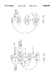
- FIG. 2 is a functional block diagram of a first embodiment of this invention.
- FIG. 3 is a functional block diagram of a second embodiment of this invention.
- FIG. 4 is a functional block diagram of a third embodiment of this invention.
- FIG. 5 is a state diagram of a local host I/O interface.
- FIG. 6 is a state diagram of a local transmit controller.
- FIG. 7 is a state diagram of a remote receive controller.
- FIG. 8 is a state diagram of a microcontroller.
- FIG. 9 is a state diagram of a remote transmit controller.
- FIG. 10 is a state diagram of a local receive controller.
- FIG. 11 is a state diagram of a portion of a video controller.
- FIG. 12 is a state diagram of another portion of a video controller.
- the terms “light” and “optic” and “optical” all refer to electromagnetic radiation in a wavelength range including infrared, visible, ultraviolet and X rays. All the embodiments presented herein include a serial transmission medium, which is preferably but not necessarily a medium for the transmission of light signals, and the term “remote” as used herein to modify, i.e. describe, a thing indicates that the thing is located at an end of the transmission medium remote from the host bus.
- a host bus 2 communicates with a local video interface 4.
- the "host bus” 2 can be any type of data processing bus such as those having an open architecture. Examples are: SBUS or SUN-BUS, MULTIBUS, ISA bus, EISA bus, VLB bus and PCI bus.
- the video interface typically has bus drivers and receivers, and a controller portion that receives data and commands from a data processor (not shown) via the bus and returns status and data to the data processor also via the bus.
- the data transfers are usually in a parallel format.
- the data 6 from the bus interface is stored in a video memory, such as a video frame buffer 8, which typically comprises an array of random access memory (RAM).
- RAM random access memory
- the stored data is an ordered group of addresses, and periodically the stored addresses are accessed and communicated in a predetermined order to a color LUT (look-up table) 9 which maps each address to a corresponding digital value, i.e. a pixel color value.
- a typical color LUT allows for many possible colors but only a limited number of colors at any given time, the limited number being the values that get loaded into the color LUT from the video interface via path 7.
- the pixel color values 10 from the color LUT are communicated to a digital-to-analog converter (DAC) 11 which converts the digital values to an analog signal 12.
- the analog signal is communicated to, and displayed on, a display device 14 such as a video display monitor that is local relative to the host bus.
- the rate at which the addresses in the frame buffer are read and applied to the color LUT is controlled by a video pixel clock which for a standard video graphics array (VGA) display having 640 columns by 480 rows is 25.175MHz.
- the typical frame refresh rate for a non-interlaced VGA display is 60 Hz.
- the local graphics display circuit is typically incorporated onto a motherboard or is made as an add-on card.
- a first embodiment of the system according to this invention is illustrated to have a circuit 16A local to the host bus 2.
- a video interface 4 performs basically the same functions as in the prior art, that is, it communicates with a data processor via the bus, responds to processor commands, and stores addresses 6 in a video frame buffer 22. Also as in the prior art the addresses are communicated to a color LUT 26 which provides corresponding digital pixel color values ("video data") 24. However instead of converting the video data to an analog signal via a DAC, this invention keeps the pixel color values in their digital form and stores them in a first-in/first-out memory (FIFO) 28.
- FIFO first-in/first-out memory
- MUX multiplexer
- the video data is communicated to a serializer (PAR./SER.) 32 that converts the data from parallel to serial form and communicates the serialized data to an optical transmitter (OPTICAL XMITTER) 34.
- the transmitter converts the serialized data to corresponding light signals and communicates them across a fiber optic cable 38 to a remote circuit 36A.
- the timing of the writing of video data 24 into the local circuit's FIFO 28 is controlled by a clock which can be separately generated or be derived from the video pixel clock discussed above in connection with FIG. 1. Since there is no local display needing to be refreshed and since transfers from the video interface 4 to the frame buffer 22 are controlled by a conventional separate interface frequency source, the FIFO write clock can be reduced in frequency from the video pixel clock without affecting the transfer rate between the processor, via the host bus, and the frame buffer.
- the timing of the video data transfers from the FIFO and through the MUX 30 to the serializer 32 is controlled by a frequency source (e.g. crystal oscillator or phase locked loop) which is selected to maximize the transfer rate of the serial link.
- a frequency source e.g. crystal oscillator or phase locked loop
- the light signals transmitted across the optical link 38 by the local circuit 16A are sensed by an optical receiver (OPTICAL RCVR) 40.
- the sensed signals are converted back to parallel form by a de-serializer (SER./PAR.) 42, and if the sensed signals contain video data, it is communicated to remote a video FIFO 44 from which the video data 46 is shifted to a remote video frame buffer 48.
- SER./PAR. de-serializer
- the video data is read from the video frame buffer and provided to preferably a flat panel display monitor 52 at a sufficient rate to meet the refresh requirements of the display panel.
- a frequency source incorporated in the remote circuit 36A (preferably crystal oscillator or phase locked loop) is used to provide the timing for de-serializing the received data and for writing to the remote video FIFO 44.
- the first embodiment of FIG. 2 also contains a feature by which a data processor, via the host bus, can send types of data ("non-video data") other than color LUT addresses to the remote circuit.
- a data processor via the host bus, can send types of data ("non-video data") other than color LUT addresses to the remote circuit.
- non-video data data
- an output interface 18A is made aware of this fact according to the design of the bus.
- the output interface then loads this data into a temporary holding memory, illustrated as an output register 54A, and interrupts a transmit controller 55.
- the transmit controller manages the reading of data from the FIFO 28, the selection of which mux 30 input passes through the mux, and further controls the serializer 32.
- the transmit controller temporarily halts the reading of video data from the FIFO, during the halt the controller causes: (1) the mux 30 to pass the non-video data from the output register to the serializer, and (2) the serializer to serialize and specially encode the non-video data.
- the controller causes: (1) the mux 30 to pass the non-video data from the output register to the serializer, and (2) the serializer to serialize and specially encode the non-video data.
- certain link commands that are encoded within the serial protocol of the link indicate to the remote circuit 36A that the data being transferred is non-video data. Once serialized and so encoded, the non-video data is transmitted to the remote circuit.
- non-video data when non-video data is received by the remote circuit's de-serializer 42, it is recognized as non-video data by a receive controller 57.
- This recognition causes the receive controller to write the data into a non-video FIFO 56 rather than the video FIFO 44 and raise an interrupt to the microcontroller 50A which remains as long as the FIFO is not empty.
- the non-video data can be, for example, pan and zoom commands, that are processed by the controller to cause the video controller 51 to vary accordingly the way the video data is transferred from the frame buffer to the display. This process is more fully explained below with reference to the embodiment of FIG. 3.
- the overall rate at which frames of video data are obtained from the local color LUT 26, serialized, transmitted over the optical link 38, sensed from the link, de-serialized and written into the remote frame buffer 48 via the remote video FIFO 44 can be called the "frame transfer rate."
- the remote frame buffer is an array of video random access memory (VRAMs) that can be accessed for writes and reads asynchronously, and so frames of video data can be read from the remote frame buffer at a rate necessary to satisfy the refresh needs of the display (e.g. 60 Hz) while frames of video data can be written into the frame buffer at the substantially reduced frame transfer rate.
- VRAMs video random access memory
- the frame transfer rate is selected according to the type of information that will be displayed on the remote monitor. For multimedia applications which include moving pictures, a transfer rate of thirty frames per second is probably adequate. For applications in which only alphanumerics are displayed, a transfer rate of ten frames per second is probably adequate. For combinations of the two, the higher rate is preferred.
- a second embodiment is illustrated to have the same structure as the first embodiment but also to include a return path from the remote circuit 36B to the host bus 2 for operator inputs coming from the location of the remote display 52.
- the operator inputs can be of any kind and number, but as illustrated they include inputs from a "mouse" 58 (which can be any kind of pointing device), a keyboard 60, an RS-232 serial port 59, and an input from an audio source 61.
- a serial controller 62 receives inputs from the mouse and keyboard, and a second one provides the RS-232 port, the two serial controllers being in communication with a microcontroller 50B via a microcontroller input/output bus 63 internal to the remote circuit.
- An audio controller 65 receives the audio signals and communicates them to the microcontroller also via the bus 63.
- the microcontroller can either process the inputs directly or send the inputs back to the host bus, or a combination of both.
- the microcontroller communicates them in parallel form, e.g. in bytes, to a serializer 66 and notifies a transmit controller 67 which in turn causes the inputs to be serialized and encoded.
- An optical transmitter 68 transmits the serialized and encoded inputs, via a second optical cable 64, to an optical receiver 70 in the local circuit 16B.
- a receive controller 71 that manages the de-serializer causes an I/O interface 18B to be aware that the I/O registers contain data from the remote circuit and what type of data has been received (keyboard stroke, audio-in, mouse, RS-232, etc.). The I/O interface then communicates this information to the data processor according to the design of the bus, e.g. by raising an interrupt.
- the I/O interface and the I/O registers are similar to the output interface 18A and output registers 54A (FIG. 2) of the first embodiment, but further include the capacity to receive, temporarily hold, and make available to the host bus non-video data from the remote circuit.
- the microcontroller 50B preferably has some video functions it can perform without needing to send all operator inputs back to a processor on the host bus. For example, it can be programmed to perform pan and zoom functions and other display related functions. It can also be used to perform diagnostics including frame buffer memory tests.
- the microcontroller is a programmable microcontroller, such as an 8031, with some read/write memory (not shown) and some read-only memory (not shown) containing the programs to perform the above-described functions.
- the 8031 also has an integrated serial port which can be used for additional I/O devices, such as a trackball.
- the microcontroller performs all reads and writes to its peripherals and initializes them upon reset, but by this configuration a host bus processor has control to change any peripheral settings.
- the serial controllers 62 are 85C30s and the audio controller 65 is a 79C30 Digital Subscriber Controller providing an audio port for both audio in and audio out such as to speakers 73.
- non-video data coming from a data processor on the host bus 2 is stored in the I/O registers 54B and multiplexed to the remote circuit between video data transfers. Eventually it is stored in the non-video FIFO 56 by the remote receive controller 57. Whenever data is present in the non-video FIFO, an interrupt is issued to the microcontroller 50B indicating that the FIFO is not empty.
- Each item of non-video data preferably comprises two bytes: a first byte being an encoded command to the microcontroller, and the second byte being an operand. Under this scheme the host processor can issue 256 different commands.
- the first byte can a "write" command to the serial port
- the second byte can be the data to be written to the port.
- a first byte can be a peripheral address (peripheral to the microcontroller) and the second byte can define the type of function to perform.
- a third embodiment is illustrated to include local circuit 16A that can be the same as the local circuit of the first embodiment (FIG. 2), but further includes a microcontroller 50C and peripherals of the microcontroller (mouse, keyboard, etc.) similar to those of the second embodiment (FIG. 3). However this embodiment does not have a return path for operator inputs such as in the second embodiment.
- the microcontroller is programmed to perform pan and zoom functions and other display related functions. It can also be used to perform diagnostics including frame buffer memory tests.
- the microcontroller is a programmable microcontroller, such as the 8031.
- the microcontroller performs all reads and writes to its peripherals and initializes them upon reset, but by this configuration a host bus processor has control to change any peripheral settings.
- the serial controllers 62 are 85C30s and the audio controller 65 is a 79C30 Digital Subscriber Controller providing an audio port for both audio-in and audio-out such as to speakers 73.
- the serializers 32 and 66 are preferably implemented using AMD AM7968 transmitter devices or equivalents, and the de-serializers 42 and 72 are preferably implemented using AMD AM7969 receiver devices or equivalents.
- the AMD AM7968 devices are operated in 9-bit mode (3 bits per RGB) and accept 9-bit data and link commands under a strobe and acknowledgment handshaking protocol.
- An acknowledgment signal from an AM7968 indicates it is ready to accept new data and link commands. If the command inputs are all logical zero, then a strobe signal communicated to the AM7968 causes it to latch internally the signals applied to its data inputs.
- the data is then encoded (4-bit/5-bit and NRZI), serialized and shifted out the device's serial outputs. If the command inputs are not all zero, the data inputs are ignored and a command symbol corresponding to the non-zero command inputs is sent via the serial outputs in response to the strobe signal.
- the AM7969 devices accept the serial signals from the AM 7968's via their serial inputs and decode them. If the received signal pattern is a command symbol, a corresponding command binary code is applied to the command output pins and a command strobe output
- the command strobe indicating to external circuitry that a command has been received and that the command code is available at the command output pins.
- the data word in this case 9-bits
- a data strobe is pulsed, the data strobe indicating to external circuitry that a data word has been received and that the data is available at the data output pins.
- the optical transmitters 34 and 68 are preferably implemented using Hewlett Packard HFBR-1414 transmitters, and the optical receivers 40 and 70 are preferably implemented using Hewlett Packard HFBR-2416 optical receivers. External 12,888MHz crystals are preferably used for the internal oscillators of the AM7968's and AM7969's.
- the I/O interface 18B and the various controllers are each preferably implemented using one or more programmable logic arrays, and each has a plurality of states, including a "ready" state from which other states originate and to which they all ultimately return. While in the ready state each controller is essentially waiting for one or more signals to prompt it to perform a certain function or series of certain functions, depending on the nature of the prompt signal. While explanation of these functions, i.e. states, which follows pertains to the embodiment of FIG. 3, they can also apply to the embodiments of FIGS. 2 and 4 where appropriate.
- the I/O interface 18B preferably responds to at least three prompts via the host bus 2 during what are commonly called host bus cycles, and at least one prompt from the local receive controller 71.
- the host bus prompts include an I/O Write signal 74, a Request I/O Read 76 signal and an I/O Read signal 78.
- the signals are termed "decoded" because for some conventional buses, such as the S-BUS, the signals are produced by an address decoder (not shown) which decodes corresponding addresses sent via the host bus.
- the I/O Write signal prompts the interface to set an I/O type flag for the benefit of the local transmit controller 55, retrieve write data (preferably two bytes of non-video data as described above) from the host bus and put it into an I/O write register (one of the registers 54B), and send a request 80 to the local transmit controller to send the write data to the remote circuit. Thereafter the interface returns to the ready state after completing the bus cycle.
- the Request I/O Read signal prompts the interface to set an I/O type flag and send a request to the local transmit controller to send an I/O read request 84 to the remote circuit in order to retrieve non-video data therefrom.
- the local receive controller 71 puts it into an appropriate I/O register 54B and sends an I/O Read Data Valid signal 82 to the interface.
- This signal prompts the interface to determine the type of data sent and to generate an appropriate host bus interrupt.
- the I/O Read signal 78 from the bus prompts the interface to retrieve the data from the I/O register in which it was stored, and put the data onto the host bus.
- the local transmit controller 55 preferably responds to at least two prompts from the I/O interface 18B, a prompt from the video FIFO 28, a prompt from the local receive controller 71, and two pseudo horizontal (H-Sync) and vertical (V-Sync) synchronizing signals preferably generated by a local video generator.
- the SBUS uses an LSI 64825 IC.
- the transmit controller retrieves and sends video data from the FIFO to the serializer 32 via the MUX 30. This is what the transmit controller is normally doing.
- the transmit controller stops sending video data for one cycle and selects the I/O registers 54B (containing the non-video data pertaining to the request) to pass through the MUX 30 and be sent to the remote circuit 36B.
- the 1st byte of the non-video data For an I/O write request, the 1st byte of the non-video data
- the remote circuit recognizes the non-video data as such because the transmit controller also causes the serializer to include in the non-video data transmission a link command unique to such a transmission, preferably a code of 0x03.
- the I/O Read Data Valid signal 82 from the local receive controller 71 prompts the local transmit controller 55 to send the remote circuit a signal 88 (I/O Read Data Received) acknowledging receipt of the read data. It does this by causing the serializer to transmit a link command corresponding to the signal, preferably a code of 0x05.
- the transmit controller is prompted by vertical (V-Sync) and horizontal (H-Sync) synchronizing signals that are produced by local frame row and column counters (not show) clocked by a local "pixel clock.”
- V-Sync vertical
- H-Sync horizontal
- the transmit controller sends the remote circuit "New Frame” and "New Row” signals, respectively, by causing the serializer to transmit corresponding link commands, preferably 0x02 and 0x01 respectively.
- the transmit controller can also be prompted by a signal 89 from the I/O interface to send the remote circuit a signal to clear the non-video FIFO of data, and it does this by causing the serializer to transmit a corresponding link command, preferably 0x04.
- the remote receive controller 57 is prompted by signals from the remote de-serializer 42 that correspond to the above-described link commands, preferably 0x01-0x05, caused to be sent by the local transmit controller 55.
- the remote receive controller For codes 0x01 and 0x02, the remote receive controller generates new row 90 and new frame 92 signals, respectively. These signals are communicated to the video controller 51 for transferring video data from the remote video FIFO to the remote video buffer.
- the receive controller writes the next two bytes of data received by the de-serializer 42 into the non-video FIFO 56 rather than the video FIFO, and it interrupts the microcontroller 50B to let it know that the non-video FIFO is not empty.
- the microcontroller subsequently retrieves the two bytes from the FIFO, decodes the command byte and acts accordingly. For code 0x04, the receive controller clears the non-video FIFO, and for code 0x05 it sets a "Local Reception Acknowledge" flag. The flag informs the microprocessor that the last I/O read data, sent from the remote circuit to the local circuit, has been read by the host.
- the microcontroller 50B can run diagnostics if a diagnostic switch is set, or otherwise enter the ready state.
- the switch is preferably a jumper.
- the microcontroller waits for an interrupt.
- the microcontroller reads an interrupt status word to determine the source or sources of the interrupt.
- the interrupt status word comprises at least all external interrupts as constituent bits. If the current highest priority interrupt was caused by the non-video FIFO not being empty, the microcontroller retrieves the next command data (the preferable two bytes) from the FIFO and determines the type of I/O command or request signified by the command data. The microcontroller then communicates accordingly with the signified I/O device controller, e.g.
- the microcontroller services the interrupt by again communicating with the corresponding I/O device controller.
- the microcontroller computes a new frame starting location for panning and writes the address of the new location in a start register (not shown) which is used to define the origin of the display.
- a remote transmit controller responds to prompts from the microcontroller.
- a prompt 94 to send a byte of data from the external serial port results in the transmit controller causing the remote serializer 66 to send a corresponding link command, 0x05, to the local receive controller 71 followed by the byte of data 96 that is provided by the microcontroller to the serializer.
- the local receive controller receives the link command, it determines the type of I/O data being sent, writes the data byte following the link command into an appropriate I/O register 54B, and then communicates a signal 82 to the I/O interface 18B that the I/O read data is valid.
- the local receive controller determines the type of I/O data being sent, writes the data byte following the link command into an appropriate I/O register 54B, and then communicates a signal 82 to the I/O interface 18B that the I/O read data is valid.
- this signal 82 causes the I/O interface to raise an appropriate host interrupt.
- prompts from the microcontroller to send keyboard, mouse, status and audio data to the local circuit result in the remote transmit controller causing the remote serializer to sent corresponding link commands (0x04, 0x03, 0x02, 0x01 respectively) each followed by a corresponding byte of data. All the data is subsequently stored by the local receive controller in appropriate I/O registers, for access by the host computer via the host bus, followed by the signal 82 informing the I/O interface of that fact.
- the remote video controller 51 as illustrated is prompted by the remote receive controller 57, the remote video FIFO 44, and vertical (V-Sync) and horizontal (H-Sync) synchronizing signals produced by a remote pixel clock generator associated with the display 52.
- V-Sync can be at 60 Hz
- H-Sync can be at 25.175 Mhz.
- the new row and new frame signals, 90 and 92, from the remote receive controller prompt the video controller to: (1) clear a video-in column address counter in response to the former, and (2) clear the FIFO, and video-in row and column address counters in response to the latter.
- the video-in row and column address counters are pointers associated with the remote video buffer 48 for loading the video data into the buffer.
- the video controller is also prompted by a signal 98 whenever the FIFO is not empty to perform writes, preferably fast page writes, from the FIFO to the VRAM of the buffer according to the video-in row and column address counters until the FIFO is empty.
- the video controller is prompted by the V-Sync 100 to reset video-out row and column address counters to a start count as determined by the contents of a start register (not shown) which is set by the microcontroller. (See FIG.
- the video-out row and column address counters are pointers associated with the remote video buffer 48 for reading the video data from the buffer to be sent to the display.
- the video controller is prompted by the H-Sync 104 to: (1) perform a read transfer from the buffer to the display by loading the current video-out row and column addresses into the VRAM and initiating a read, (2) increment the video-out row address counter depending on the current zoom level, and (3) refresh the VRAM depending on the specific requirements of the VRAM integrated circuits (ICs) and the horizontal sweep rate.
- the video-out row counter would be incremented every H-Sync
- the column counter would be incremented every pixel clock.
- the video-out row counter would be incremented once per two H-Syncs, and the column counter would be incremented once per two pixel clocks.
- the video-out row counter would be incremented once per four H-Syncs, and the column counter would be incremented once per four pixel clocks.
- the number of times the VRAM is refreshed per H-sync is preferably equal to, or greater than, the minimum refresh rate specified for the VRAM ICs divided by the horizontal sweep rate.
- the video controller 51 as illustrated is also prompted by a signal 106 indicating times when video blanking for the display 52 is not being asserted.
- the video controller reads video data from the remote video buffer 48 for transfer to the display and increments the column counter.
- corresponding signals from the microcontroller 50B cause the video controller to wait a corresponding number of pixel clocks before transferring the next video data from the buffer to the display.
- the rate at which digital bits are transferred across the serial link depends not only on the frame transfer rate but also on the number of pixels per frame, the number of bits per pixel and the number and frequency of non-video data transfers.
- the selected frame transfer rate is thirty frames per second
- each frame comprises 640 columns by 480 rows of pixels
- each pixel is defined by a nine-bit value
- two additional bits are needed to asynchronously transfer each pixel value across the serial link (e.g. 5B/6B encoding of the four most significant bits of a byte and 4B/5B encoding of the four least significant bits of the byte).
- the minimum bit transfer rate is calculated as follows: 30 frames/sec.
- ⁇ (640 ⁇ 480) pixels/frame ⁇ 11 bits/pixel 101,376,000 bits/sec.
- the preferred embodiments of the serial link have a 135 megabits/second capacity so the additional bandwidth (approximately 34 megabits/second) can be used to multiplex the non-video data transfers with the video pixel transfers without impacting the frame transfer rates.
- the local circuit's video frame buffer is updated at its regular rate, and the remote display monitor is refreshed at its normal rate.
- the video data can be transferred from the local circuit to the remote circuit at a much slower rate. This is because humans typically cannot perceive image changes occurring from one refresh to the next as long as the monitor's normal refresh rate is maintained to avoid noticeable flicker. So the rate at which the remote circuit's video frame buffer can be updated is a rate less then the remote display's refresh rate, depending only on humanly perceptible display changes rather than the refresh rate required by the remote display.
- the video data transmitted to the remote circuit does not go through an analog stage. This is more efficient because typical transistor flat panel displays are inherently digital. In this way the analog stage is avoided entirely. It is also important to note that the video data are the digital values from the local color LUT, and that there is no decrease in performance in communications between the graphics programs being run by a host processor and the LUT. This is advantageous because conventional graphics programs typically manipulate the color LUT (write into and read from) extensively. So from the standpoint of graphics programs, this invention is transparent because it behaves exactly as a conventional graphics circuit in so far as data transfers to and from the color LUT.
- the remote terminal will still retain its last image.
- the remote video frame buffer allows the remote monitor refresh to be asynchronous with the host computer's data transfers into the local video frame buffer.
- each of the host buses illustrated in the drawings need not be an open bus, but rather can be a closed bus or even a dedicated communication channel.
- the remote flat panel displays of all embodiments discussed above could be replaced by analog displays in which case a DAC would be interposed between the remote frame buffers and the analog displays.
Abstract
Description
Claims (20)
Priority Applications (1)
| Application Number | Priority Date | Filing Date | Title |
|---|---|---|---|
| US08/422,580 US5604509A (en) | 1995-04-14 | 1995-04-14 | Remote display monitor system |
Applications Claiming Priority (1)
| Application Number | Priority Date | Filing Date | Title |
|---|---|---|---|
| US08/422,580 US5604509A (en) | 1995-04-14 | 1995-04-14 | Remote display monitor system |
Publications (1)
| Publication Number | Publication Date |
|---|---|
| US5604509A true US5604509A (en) | 1997-02-18 |
Family
ID=23675498
Family Applications (1)
| Application Number | Title | Priority Date | Filing Date |
|---|---|---|---|
| US08/422,580 Expired - Fee Related US5604509A (en) | 1995-04-14 | 1995-04-14 | Remote display monitor system |
Country Status (1)
| Country | Link |
|---|---|
| US (1) | US5604509A (en) |
Cited By (44)
| Publication number | Priority date | Publication date | Assignee | Title |
|---|---|---|---|---|
| US5721842A (en) * | 1995-08-25 | 1998-02-24 | Apex Pc Solutions, Inc. | Interconnection system for viewing and controlling remotely connected computers with on-screen video overlay for controlling of the interconnection switch |
| US5748871A (en) * | 1995-08-11 | 1998-05-05 | Symbios Logic Inc. | Dual bus architecture for a storage device |
| US5825336A (en) * | 1995-07-05 | 1998-10-20 | Matsushita Electric Industrial Co., Ltd | Remote operation apparatus |
| US5850226A (en) * | 1996-02-29 | 1998-12-15 | Ultra-High Speed Network And Computer Technology Laboratories | Method of transferring and displaying 3-D shape data |
| US6032126A (en) * | 1995-06-14 | 2000-02-29 | Gilbarco, Inc. | Audio and audio/video operator intercom for a fuel dispenser |
| US6304895B1 (en) | 1997-08-22 | 2001-10-16 | Apex Inc. | Method and system for intelligently controlling a remotely located computer |
| US6321287B1 (en) * | 1998-10-19 | 2001-11-20 | Dell Usa, L.P. | Console redirection for a computer system |
| US6397256B1 (en) * | 1999-01-27 | 2002-05-28 | International Business Machines Corporation | Monitoring system for computers and internet browsers |
| US20020091850A1 (en) * | 1992-10-23 | 2002-07-11 | Cybex Corporation | System and method for remote monitoring and operation of personal computers |
| US6560641B1 (en) | 2000-03-29 | 2003-05-06 | Unisys Corporation | System, method, and adapter card for remote console emulation including remote control of a peripheral device |
| US6606098B1 (en) * | 1999-03-19 | 2003-08-12 | Ati International Srl | Method and apparatus having an extended video graphics bus |
| US20030234790A1 (en) * | 2002-06-24 | 2003-12-25 | Hochmuth Roland M. | System and method for grabbing frames of graphical data |
| WO2004015675A1 (en) * | 2002-07-26 | 2004-02-19 | Sim2 Multimedia S.P.A. | Signals transmission system for display |
| NL1021652C2 (en) * | 2002-10-15 | 2004-04-16 | Johan Ritser Kuipers | Image generating system, sends digital information from first computer to second computer for loading directly into frame buffer |
| US6732067B1 (en) | 1999-05-12 | 2004-05-04 | Unisys Corporation | System and adapter card for remote console emulation |
| US6760785B1 (en) | 2000-03-29 | 2004-07-06 | Unisys Corporation | Method, apparatus, and computer program product for establishing communications between an adapter card and a host processor running in a bios supported environment |
| US20040212638A1 (en) * | 1997-08-12 | 2004-10-28 | Berger Brent Henry | Control system for an electronic sign (video display system) |
| US20050063108A1 (en) * | 2003-09-24 | 2005-03-24 | Belkin Corporation | Distance extender and method making use of same |
| US20050132036A1 (en) * | 2003-12-13 | 2005-06-16 | Samsung Electronics Co., Ltd | Display apparatus management system and method thereof |
| EP1557811A1 (en) * | 2004-01-23 | 2005-07-27 | Siemens Schweiz AG | Transmission apparatus for wireless coupling of an image display device to a computer |
| US20060017696A1 (en) * | 2004-07-21 | 2006-01-26 | Microsoft Corporation | Input device with a zoom apparatus |
| US20060048198A1 (en) * | 2004-08-24 | 2006-03-02 | Hewlett-Packard Development Company, L.P. | Establishing remote connections |
| US20060161689A1 (en) * | 2005-01-18 | 2006-07-20 | Hewlett-Packard Development Company, L.P. | Apparatus and systems for monitoring communication |
| US20060200585A1 (en) * | 2005-02-04 | 2006-09-07 | Martin Weigert | Communication arrangement and method for bidirectionally transmitting data between a first communication unit and a second communication unit |
| US20070033265A1 (en) * | 1998-09-22 | 2007-02-08 | Avocent Huntsville Corporation | System and method for accessing and operating personal computers remotely |
| US7197718B1 (en) | 1999-10-18 | 2007-03-27 | Sharp Laboratories Of America, Inc. | Interactive virtual area browser for selecting and rescaling graphical representations of displayed data |
| US20070291004A1 (en) * | 1999-08-25 | 2007-12-20 | Avocent Redmond Corporation | KVM switch including a terminal emulator |
| US7496666B2 (en) | 1997-10-28 | 2009-02-24 | Raritan Americas, Inc. | Multi-user computer system |
| US7667733B1 (en) | 2003-07-18 | 2010-02-23 | Oswald David L | Computer monitor receiver |
| US20100117933A1 (en) * | 1998-04-30 | 2010-05-13 | David Gothard | High resolution computer operated digital display system |
| US20100189219A1 (en) * | 2009-01-29 | 2010-07-29 | Searete Llc, A Limited Liability Corporation Of The State Of Delaware | Diagnostic delivery service |
| US20100309208A1 (en) * | 1998-04-30 | 2010-12-09 | Dave Gothard | Remote Control Electronic Display System |
| US7870504B1 (en) * | 2003-10-01 | 2011-01-11 | TestPlant Inc. | Method for monitoring a graphical user interface on a second computer display from a first computer |
| US8009173B2 (en) | 2006-08-10 | 2011-08-30 | Avocent Huntsville Corporation | Rack interface pod with intelligent platform control |
| US20120331194A1 (en) * | 2011-06-23 | 2012-12-27 | Apple Inc. | Interface extender for portable electronic devices |
| US8427489B2 (en) | 2006-08-10 | 2013-04-23 | Avocent Huntsville Corporation | Rack interface pod with intelligent platform control |
| US9524008B1 (en) * | 2012-09-11 | 2016-12-20 | Pixelworks, Inc. | Variable frame rate timing controller for display devices |
| CN109272943A (en) * | 2018-10-15 | 2019-01-25 | 昆山龙腾光电有限公司 | A kind of backlight control system of display device |
| CN110232882A (en) * | 2019-06-06 | 2019-09-13 | 深圳市福瑞达显示技术有限公司 | Fan screen display control method and its system based on linux system |
| WO2021129886A1 (en) * | 2019-12-23 | 2021-07-01 | 威创集团股份有限公司 | Method for controlling screen display and electronic device |
| US11228733B2 (en) | 2012-07-11 | 2022-01-18 | Cyclops Technology Group, Llc | Surveillance system and associated methods of use |
| US11507496B2 (en) | 2016-02-10 | 2022-11-22 | Eggplant Limited | Method of, and apparatus for, testing computer hardware and software |
| US11507494B2 (en) | 2016-02-10 | 2022-11-22 | Eggplant Limited | Method of, and apparatus for, testing computer hardware and software |
| US11599265B1 (en) * | 2021-12-30 | 2023-03-07 | Motorola Solutions, Inc. | Enhancement of non-touchscreen enabled mobile applications |
Citations (3)
| Publication number | Priority date | Publication date | Assignee | Title |
|---|---|---|---|---|
| US5268676A (en) * | 1987-09-11 | 1993-12-07 | Cybex Corporation | Computer-monitor extended range communications link |
| US5469183A (en) * | 1992-06-12 | 1995-11-21 | Matsushita Electric Industrial Co., Ltd. | Synchronous display control apparatus |
| US5526354A (en) * | 1993-06-17 | 1996-06-11 | International Business Machines Corporation | Packet communication terminal having synchronized audio and cursor data |
-
1995
- 1995-04-14 US US08/422,580 patent/US5604509A/en not_active Expired - Fee Related
Patent Citations (3)
| Publication number | Priority date | Publication date | Assignee | Title |
|---|---|---|---|---|
| US5268676A (en) * | 1987-09-11 | 1993-12-07 | Cybex Corporation | Computer-monitor extended range communications link |
| US5469183A (en) * | 1992-06-12 | 1995-11-21 | Matsushita Electric Industrial Co., Ltd. | Synchronous display control apparatus |
| US5526354A (en) * | 1993-06-17 | 1996-06-11 | International Business Machines Corporation | Packet communication terminal having synchronized audio and cursor data |
Cited By (64)
| Publication number | Priority date | Publication date | Assignee | Title |
|---|---|---|---|---|
| USRE44814E1 (en) | 1992-10-23 | 2014-03-18 | Avocent Huntsville Corporation | System and method for remote monitoring and operation of personal computers |
| US20020091850A1 (en) * | 1992-10-23 | 2002-07-11 | Cybex Corporation | System and method for remote monitoring and operation of personal computers |
| US6032126A (en) * | 1995-06-14 | 2000-02-29 | Gilbarco, Inc. | Audio and audio/video operator intercom for a fuel dispenser |
| US5825336A (en) * | 1995-07-05 | 1998-10-20 | Matsushita Electric Industrial Co., Ltd | Remote operation apparatus |
| US5748871A (en) * | 1995-08-11 | 1998-05-05 | Symbios Logic Inc. | Dual bus architecture for a storage device |
| US7818367B2 (en) | 1995-08-25 | 2010-10-19 | Avocent Redmond Corp. | Computer interconnection system |
| US5884096A (en) * | 1995-08-25 | 1999-03-16 | Apex Pc Solutions, Inc. | Interconnection system for viewing and controlling remotely connected computers with on-screen video overlay for controlling of the interconnection switch |
| US5937176A (en) * | 1995-08-25 | 1999-08-10 | Apex Pc Solutions, Inc. | Interconnection system having circuits to packetize keyboard/mouse electronic signals from plural workstations and supply to keyboard/mouse input of remote computer systems through a crosspoint switch |
| US20050232260A1 (en) * | 1995-08-25 | 2005-10-20 | Avocent Redmond Corporation | Computer interconnection system |
| US5721842A (en) * | 1995-08-25 | 1998-02-24 | Apex Pc Solutions, Inc. | Interconnection system for viewing and controlling remotely connected computers with on-screen video overlay for controlling of the interconnection switch |
| US5850226A (en) * | 1996-02-29 | 1998-12-15 | Ultra-High Speed Network And Computer Technology Laboratories | Method of transferring and displaying 3-D shape data |
| US7646357B2 (en) * | 1997-08-12 | 2010-01-12 | Daktronics, Inc. | Control system for an electronic sign (video display system) |
| US20040212638A1 (en) * | 1997-08-12 | 2004-10-28 | Berger Brent Henry | Control system for an electronic sign (video display system) |
| US6304895B1 (en) | 1997-08-22 | 2001-10-16 | Apex Inc. | Method and system for intelligently controlling a remotely located computer |
| US7496666B2 (en) | 1997-10-28 | 2009-02-24 | Raritan Americas, Inc. | Multi-user computer system |
| US20100117933A1 (en) * | 1998-04-30 | 2010-05-13 | David Gothard | High resolution computer operated digital display system |
| US20100309208A1 (en) * | 1998-04-30 | 2010-12-09 | Dave Gothard | Remote Control Electronic Display System |
| US8330613B2 (en) | 1998-04-30 | 2012-12-11 | Locke International Teast | Remote control electronic display system |
| US7747702B2 (en) | 1998-09-22 | 2010-06-29 | Avocent Huntsville Corporation | System and method for accessing and operating personal computers remotely |
| US20070033265A1 (en) * | 1998-09-22 | 2007-02-08 | Avocent Huntsville Corporation | System and method for accessing and operating personal computers remotely |
| US6321287B1 (en) * | 1998-10-19 | 2001-11-20 | Dell Usa, L.P. | Console redirection for a computer system |
| US6397256B1 (en) * | 1999-01-27 | 2002-05-28 | International Business Machines Corporation | Monitoring system for computers and internet browsers |
| US6606098B1 (en) * | 1999-03-19 | 2003-08-12 | Ati International Srl | Method and apparatus having an extended video graphics bus |
| US6732067B1 (en) | 1999-05-12 | 2004-05-04 | Unisys Corporation | System and adapter card for remote console emulation |
| US20080082705A1 (en) * | 1999-08-25 | 2008-04-03 | Avocent Redmond Corporation | KVM switch including a terminal emulator |
| US20070291004A1 (en) * | 1999-08-25 | 2007-12-20 | Avocent Redmond Corporation | KVM switch including a terminal emulator |
| US8269783B2 (en) | 1999-08-25 | 2012-09-18 | Avocent Redmond Corporation | KVM switch including a terminal emulator |
| US7197718B1 (en) | 1999-10-18 | 2007-03-27 | Sharp Laboratories Of America, Inc. | Interactive virtual area browser for selecting and rescaling graphical representations of displayed data |
| US6760785B1 (en) | 2000-03-29 | 2004-07-06 | Unisys Corporation | Method, apparatus, and computer program product for establishing communications between an adapter card and a host processor running in a bios supported environment |
| US6560641B1 (en) | 2000-03-29 | 2003-05-06 | Unisys Corporation | System, method, and adapter card for remote console emulation including remote control of a peripheral device |
| US7064765B2 (en) | 2002-06-24 | 2006-06-20 | Hewlett-Packard Development Company, L.P. | System and method for grabbing frames of graphical data |
| US20030234790A1 (en) * | 2002-06-24 | 2003-12-25 | Hochmuth Roland M. | System and method for grabbing frames of graphical data |
| WO2004015675A1 (en) * | 2002-07-26 | 2004-02-19 | Sim2 Multimedia S.P.A. | Signals transmission system for display |
| GB2406729A (en) * | 2002-07-26 | 2005-04-06 | Sim2 Multimedia Spa | Signals transmission system for display |
| NL1021652C2 (en) * | 2002-10-15 | 2004-04-16 | Johan Ritser Kuipers | Image generating system, sends digital information from first computer to second computer for loading directly into frame buffer |
| US7667733B1 (en) | 2003-07-18 | 2010-02-23 | Oswald David L | Computer monitor receiver |
| US7259482B2 (en) | 2003-09-24 | 2007-08-21 | Belkin International, Inc. | Distance extender and method making use of same |
| US20050063108A1 (en) * | 2003-09-24 | 2005-03-24 | Belkin Corporation | Distance extender and method making use of same |
| US20070284949A1 (en) * | 2003-09-24 | 2007-12-13 | Belkin Corporation | Distance Extender |
| US7432619B2 (en) | 2003-09-24 | 2008-10-07 | Belkin International, Inc. | Distance extender |
| US9658931B2 (en) | 2003-10-01 | 2017-05-23 | TestPlant Inc. | Method for monitoring a graphical user interface on a second computer display from a first computer |
| US9477567B2 (en) | 2003-10-01 | 2016-10-25 | Testplant, Inc. | Method for monitoring a graphical user interface on a second computer display from a first computer |
| US7870504B1 (en) * | 2003-10-01 | 2011-01-11 | TestPlant Inc. | Method for monitoring a graphical user interface on a second computer display from a first computer |
| US7831714B2 (en) * | 2003-12-13 | 2010-11-09 | Samsung Electronics Co., Ltd. | Display apparatus management system and method thereof |
| US20050132036A1 (en) * | 2003-12-13 | 2005-06-16 | Samsung Electronics Co., Ltd | Display apparatus management system and method thereof |
| EP1557811A1 (en) * | 2004-01-23 | 2005-07-27 | Siemens Schweiz AG | Transmission apparatus for wireless coupling of an image display device to a computer |
| US20060017696A1 (en) * | 2004-07-21 | 2006-01-26 | Microsoft Corporation | Input device with a zoom apparatus |
| US7369121B2 (en) | 2004-07-21 | 2008-05-06 | Microsoft Corporation | Input device with a zoom apparatus |
| US20060048198A1 (en) * | 2004-08-24 | 2006-03-02 | Hewlett-Packard Development Company, L.P. | Establishing remote connections |
| US20060161689A1 (en) * | 2005-01-18 | 2006-07-20 | Hewlett-Packard Development Company, L.P. | Apparatus and systems for monitoring communication |
| US20060200585A1 (en) * | 2005-02-04 | 2006-09-07 | Martin Weigert | Communication arrangement and method for bidirectionally transmitting data between a first communication unit and a second communication unit |
| US7602739B2 (en) * | 2005-02-04 | 2009-10-13 | Avago Technologies Fiber Ip (Singapore) Pte. Ltd. | Communication arrangement and method for bidirectionally transmitting data between a first communication unit and a second communication unit |
| US8009173B2 (en) | 2006-08-10 | 2011-08-30 | Avocent Huntsville Corporation | Rack interface pod with intelligent platform control |
| US8427489B2 (en) | 2006-08-10 | 2013-04-23 | Avocent Huntsville Corporation | Rack interface pod with intelligent platform control |
| US20100189219A1 (en) * | 2009-01-29 | 2010-07-29 | Searete Llc, A Limited Liability Corporation Of The State Of Delaware | Diagnostic delivery service |
| US20120331194A1 (en) * | 2011-06-23 | 2012-12-27 | Apple Inc. | Interface extender for portable electronic devices |
| US11228733B2 (en) | 2012-07-11 | 2022-01-18 | Cyclops Technology Group, Llc | Surveillance system and associated methods of use |
| US9524008B1 (en) * | 2012-09-11 | 2016-12-20 | Pixelworks, Inc. | Variable frame rate timing controller for display devices |
| US11507496B2 (en) | 2016-02-10 | 2022-11-22 | Eggplant Limited | Method of, and apparatus for, testing computer hardware and software |
| US11507494B2 (en) | 2016-02-10 | 2022-11-22 | Eggplant Limited | Method of, and apparatus for, testing computer hardware and software |
| CN109272943A (en) * | 2018-10-15 | 2019-01-25 | 昆山龙腾光电有限公司 | A kind of backlight control system of display device |
| CN110232882A (en) * | 2019-06-06 | 2019-09-13 | 深圳市福瑞达显示技术有限公司 | Fan screen display control method and its system based on linux system |
| WO2021129886A1 (en) * | 2019-12-23 | 2021-07-01 | 威创集团股份有限公司 | Method for controlling screen display and electronic device |
| US11599265B1 (en) * | 2021-12-30 | 2023-03-07 | Motorola Solutions, Inc. | Enhancement of non-touchscreen enabled mobile applications |
Similar Documents
| Publication | Publication Date | Title |
|---|---|---|
| US5604509A (en) | Remote display monitor system | |
| US5136695A (en) | Apparatus and method for updating a remote video display from a host computer | |
| US4536856A (en) | Method of and apparatus for controlling the display of video signal information | |
| US4642794A (en) | Video update FIFO buffer | |
| US20010030649A1 (en) | Method for displaying image, image display system, host system, image display apparatus, and interface for display | |
| US5276458A (en) | Display system | |
| US20040017333A1 (en) | Universal serial bus display unit | |
| US7242370B2 (en) | Display apparatus, method of controlling the same, and multidisplay system | |
| EP0788048B1 (en) | Display apparatus interface | |
| US6054980A (en) | Display unit displaying images at a refresh rate less than the rate at which the images are encoded in a received display signal | |
| US4642789A (en) | Video memory controller | |
| JPH10504113A (en) | Variable pixel depth and format for video windows | |
| US6847335B1 (en) | Serial communication circuit with display detector interface bypass circuit | |
| EP0708433B1 (en) | Display control apparatus and method | |
| EP0918278B1 (en) | Circuit for simultaneous driving of liquid crystal display panel and television | |
| EP0786756B1 (en) | Data transfer arbitration for display controller | |
| US6825845B2 (en) | Virtual frame buffer control system | |
| US5611041A (en) | Memory bandwidth optimization | |
| US6091457A (en) | Method and apparatus for refreshing a display screen of a television system with images representing network application data | |
| US5760784A (en) | System and method for pacing the rate of display of decompressed video data | |
| JPS61233776A (en) | Video apparatus | |
| US5929868A (en) | Method and apparatus for computer display memory management | |
| EP0465063A2 (en) | Television image processing apparatus | |
| EP0422300B1 (en) | Display system with graphics cursor | |
| JP3253778B2 (en) | Display system, display control method, and electronic device |
Legal Events
| Date | Code | Title | Description |
|---|---|---|---|
| AS | Assignment |
Owner name: ADVENT DESIGN, INC., CALIFORNIA Free format text: ASSIGNMENT OF ASSIGNORS INTEREST;ASSIGNORS:MOORE, RONALD L.;RITTMASTER, THOMAS P.;LUPFER, THOMAS H.;REEL/FRAME:007661/0697 Effective date: 19950414 |
|
| AS | Assignment |
Owner name: INDUSTRIAL COMPUTER SOURCE, CALIFORNIA Free format text: ASSIGNMENT OF ASSIGNORS INTEREST;ASSIGNOR:ADVENT DESIGN;REEL/FRAME:008454/0458 Effective date: 19970328 |
|
| AS | Assignment |
Owner name: MORGAN GUARANTY TRUST COMPANY OF NEW YORK, AS ADMI Free format text: SECURITY AGREEMENT;ASSIGNORS:DYNATACH CORPORATION (MA CORPORATION);TELECOMMUNICATIONS TECHNIQUES CO., LLC. (DE CORPORATION);AIRSHOW, INC. (CA CORPORATION);AND OTHERS;REEL/FRAME:009350/0738 Effective date: 19980521 |
|
| AS | Assignment |
Owner name: MORGAN GUARANTY TRUST COMPANY OF NEW YORK, AS ADMI Free format text: CORRECTIVE ASSIGNMENT TO CORRECT INCORRECT ASSIGNOR DYNATACH CORPORATION AT REEL/FRAME 9350;ASSIGNORS:DYNATECH CORPORATION (MA CORPORATION);TELECOMMUNICATIONS TECHNIQUES CO., LLC (DE CORPORATION);AIRSHOW, INC. (CA CORPORATION);AND OTHERS;REEL/FRAME:010272/0256 Effective date: 19980521 |
|
| AS | Assignment |
Owner name: ICS ADVENT CORPORATION, CALIFORNIA Free format text: MERGER;ASSIGNOR:ICS ADVENT CORPORATION;REEL/FRAME:010506/0310 Effective date: 19991210 |
|
| AS | Assignment |
Owner name: MORGAN GUARANTY TRUST COMPANY OF NEW YORK, AS ADMI Free format text: CONDITIONAL ASSIGNMENT OF AND SECURITY INTEREST IN PATENT RIGHTS;ASSIGNOR:ICSADVENT CORPORATION (DE CORPORATION);REEL/FRAME:011064/0062 Effective date: 20000814 |
|
| REMI | Maintenance fee reminder mailed | ||
| FPAY | Fee payment |
Year of fee payment: 4 |
|
| SULP | Surcharge for late payment | ||
| AS | Assignment |
Owner name: ICSADVENT CORPORATION, CALIFORNIA Free format text: RELEASE OF SECURITY INTEREST;ASSIGNOR:MORGAN GUARANTY TRUST COMPANY OF NEW YORK, AS ADMINISTRATIVE AGENT;REEL/FRAME:012365/0188 Effective date: 20011026 |
|
| REMI | Maintenance fee reminder mailed | ||
| LAPS | Lapse for failure to pay maintenance fees | ||
| STCH | Information on status: patent discontinuation |
Free format text: PATENT EXPIRED DUE TO NONPAYMENT OF MAINTENANCE FEES UNDER 37 CFR 1.362 |
|
| FP | Lapsed due to failure to pay maintenance fee |
Effective date: 20050218 |