US5623927A - Multiple patient breast scanning on a magnetic resonance imaging apparatus - Google Patents

Multiple patient breast scanning on a magnetic resonance imaging apparatus Download PDF

Info

Publication number
US5623927A
US5623927A US08/456,508 US45650895A US5623927A US 5623927 A US5623927 A US 5623927A US 45650895 A US45650895 A US 45650895A US 5623927 A US5623927 A US 5623927A
Authority
US
United States
Prior art keywords
patient
breast
magnetic resonance
magnet
radio frequency
Prior art date
Legal status (The legal status is an assumption and is not a legal conclusion. Google has not performed a legal analysis and makes no representation as to the accuracy of the status listed.)
Expired - Lifetime
Application number
US08/456,508
Inventor
Raymond V. Damadian
Jan Votruba
Current Assignee (The listed assignees may be inaccurate. Google has not performed a legal analysis and makes no representation or warranty as to the accuracy of the list.)
Fonar Corp
Original Assignee
Fonar Corp
Priority date (The priority date is an assumption and is not a legal conclusion. Google has not performed a legal analysis and makes no representation as to the accuracy of the date listed.)
Filing date
Publication date
Priority claimed from US07/952,327 external-priority patent/US5606970A/en
Application filed by Fonar Corp filed Critical Fonar Corp
Priority to US08/456,508 priority Critical patent/US5623927A/en
Application granted granted Critical
Publication of US5623927A publication Critical patent/US5623927A/en
Anticipated expiration legal-status Critical
Expired - Lifetime legal-status Critical Current

Links

Images

Classifications

    • GPHYSICS
    • G01MEASURING; TESTING
    • G01RMEASURING ELECTRIC VARIABLES; MEASURING MAGNETIC VARIABLES
    • G01R33/00Arrangements or instruments for measuring magnetic variables
    • G01R33/20Arrangements or instruments for measuring magnetic variables involving magnetic resonance
    • G01R33/28Details of apparatus provided for in groups G01R33/44 - G01R33/64
    • G01R33/38Systems for generation, homogenisation or stabilisation of the main or gradient magnetic field
    • G01R33/381Systems for generation, homogenisation or stabilisation of the main or gradient magnetic field using electromagnets
    • AHUMAN NECESSITIES
    • A61MEDICAL OR VETERINARY SCIENCE; HYGIENE
    • A61BDIAGNOSIS; SURGERY; IDENTIFICATION
    • A61B5/00Measuring for diagnostic purposes; Identification of persons
    • A61B5/05Detecting, measuring or recording for diagnosis by means of electric currents or magnetic fields; Measuring using microwaves or radio waves 
    • A61B5/055Detecting, measuring or recording for diagnosis by means of electric currents or magnetic fields; Measuring using microwaves or radio waves  involving electronic [EMR] or nuclear [NMR] magnetic resonance, e.g. magnetic resonance imaging
    • AHUMAN NECESSITIES
    • A61MEDICAL OR VETERINARY SCIENCE; HYGIENE
    • A61BDIAGNOSIS; SURGERY; IDENTIFICATION
    • A61B5/00Measuring for diagnostic purposes; Identification of persons
    • A61B5/70Means for positioning the patient in relation to the detecting, measuring or recording means
    • A61B5/704Tables
    • AHUMAN NECESSITIES
    • A61MEDICAL OR VETERINARY SCIENCE; HYGIENE
    • A61BDIAGNOSIS; SURGERY; IDENTIFICATION
    • A61B5/00Measuring for diagnostic purposes; Identification of persons
    • A61B5/70Means for positioning the patient in relation to the detecting, measuring or recording means
    • A61B5/708Breast positioning means
    • GPHYSICS
    • G01MEASURING; TESTING
    • G01RMEASURING ELECTRIC VARIABLES; MEASURING MAGNETIC VARIABLES
    • G01R33/00Arrangements or instruments for measuring magnetic variables
    • G01R33/20Arrangements or instruments for measuring magnetic variables involving magnetic resonance
    • G01R33/28Details of apparatus provided for in groups G01R33/44 - G01R33/64
    • G01R33/32Excitation or detection systems, e.g. using radio frequency signals
    • G01R33/34Constructional details, e.g. resonators, specially adapted to MR
    • G01R33/34046Volume type coils, e.g. bird-cage coils; Quadrature bird-cage coils; Circularly polarised coils
    • GPHYSICS
    • G01MEASURING; TESTING
    • G01RMEASURING ELECTRIC VARIABLES; MEASURING MAGNETIC VARIABLES
    • G01R33/00Arrangements or instruments for measuring magnetic variables
    • G01R33/20Arrangements or instruments for measuring magnetic variables involving magnetic resonance
    • G01R33/28Details of apparatus provided for in groups G01R33/44 - G01R33/64
    • G01R33/32Excitation or detection systems, e.g. using radio frequency signals
    • G01R33/34Constructional details, e.g. resonators, specially adapted to MR
    • G01R33/341Constructional details, e.g. resonators, specially adapted to MR comprising surface coils
    • GPHYSICS
    • G01MEASURING; TESTING
    • G01RMEASURING ELECTRIC VARIABLES; MEASURING MAGNETIC VARIABLES
    • G01R33/00Arrangements or instruments for measuring magnetic variables
    • G01R33/20Arrangements or instruments for measuring magnetic variables involving magnetic resonance
    • G01R33/44Arrangements or instruments for measuring magnetic variables involving magnetic resonance using nuclear magnetic resonance [NMR]
    • G01R33/48NMR imaging systems
    • G01R33/58Calibration of imaging systems, e.g. using test probes, Phantoms; Calibration objects or fiducial markers such as active or passive RF coils surrounding an MR active material

Definitions

  • the present invention pertains to medical nuclear magnetic resonance scanners, particularly as employed during magnetic resonance imaging (MRI) procedures of the breast.
  • MRI magnetic resonance imaging
  • This information typically is displayed as an image with intensity corresponding to the concentration and/or physical state of certain nuclei of interest.
  • concentrations of physical state of different substances ordinarily differ for differing kinds of tissues within the body, and also permit the physician to see abnormalities, such as tumors, within the body. Accordingly, MR imaging techniques have been widely adopted by physicians.
  • Present day magnetic resonance scanners typically possess a patient handling system which is in close proximity to an aperture of the magnet responsible for generating the primary magnetic field.
  • the patient handling system is used to position the anatomical region of interest to be investigated during an MRI procedure, into a portion of the primary magnetic field referred to as the imaging volume.
  • the patient is removed from the magnet and unloaded from the patient handling system, and preparations for the next patient are made. Such a series of events is repeated for each patient to be subjected to an MRI procedure.
  • Magnetic resonance imaging practiced in such a way limits the utilization of the magnetic resonance scanner since only one patient at a time is submitted to a magnetic resonance imaging procedure. Such practices contribute to the high cost of medical care and slow the dissemination of this valuable diagnostic tool.
  • the present invention comprises methods and apparatus which enhance throughput when imaging the breast region of a patient on Thus medical magnetic resonance scanners.
  • the present invention provides for access to the imaging volume of the primary magnetic field through additional apertures as exist in the magnet structure.
  • Magnetic resonance scanners in use today make use of one of the three types of magnets: superconducting, resistive and permanent. Virtually every magnet in present use has a symmetrical structure with two available apertures capable of providing access to the imaging volume.
  • the present invention makes use of both apertures by means of a separate patient handling system at each aperture, each of which permits placement of a patient to be subjected to a magnetic resonance imaging procedure in the imaging volume.
  • the time required for a magnetic resonance (MR) imaging procedure has two major components.
  • the first component is related to conducting a scan protocol which is the time required to collect the spatially encoded magnetic resonance imaging data. Imaging data will subsequently be processed into magnetic resonance images.
  • the scan protocol time accounts for anywhere from 30% to 70% of the total imaging procedure time, depending upon the precise nature of the scan protocol being used.
  • the second major component of the MR imaging procedure which accounts for the remainder of the total time, is the patient handling time.
  • Patient handling time is comprised of preparation of the patient, loading the patient onto the patient handling system, placing the patient through the magnet aperture into the imaging volume, positioning the radio frequency coils onto or about the patient, attaching any ancillary equipment necessary for a particular patient or scan protocol, removing the patient following completion of the scan protocol, unloading the patient from the patient handling system, and preparing the scanner for the next patient.
  • the present invention addresses the need to reduce the amount of time spent on each of the two major time components of the magnetic resonance scanning procedure, particularly as related to breast scanning.
  • two patient handling systems permit handling of a patient, in preparation for positioning in the imaging volume while the scan protocol of another magnetic resonance imaging procedure is being conducted on a different patient.
  • the different patient had been positioned previously in the imaging volume on a separate patient handling system. This procedure permits the time overlapping of the two major time components of separate magnetic resonance imaging procedures.
  • two patients to be subjected to a magnetic resonance imaging procedure may be positioned in the imaging volume simultaneously, where each one is afforded access to the imaging volume through a separate aperture by means of a separate patient handling system.
  • a single scan protocol which is comprised of multiple scans, may be conducted, resulting in simultaneous magnetic resonance imaging data acquisition for both patients.
  • Such a procedure results in a substantial reduction of the scan protocol time component of the magnetic resonance imaging procedure, and increased patient throughput.
  • the present invention has been described in terms of two patients, and two patient handling systems with each one providing access to an imaging volume through a separate and distinct aperture of the primary magnet. It will be appreciated that a scanner with more than two primary magnet apertures, and more than two patient handling systems capable of scanning a multiplicity of patients, is desirable and within the scope of the present invention.
  • another embodiment of the present invention includes multiple, or more specifically at least two, patient handling systems each of which is capable of positioning the breast region of a patient, into the imaging volume of the primary magnetic field. Additional throughput enhancement will result as more magnet apertures are utilized and the degree of enhancement will be generally proportional to the number of patient handling systems employed up to a limit where the imaging volume is not large enough to accommodate additional patients.
  • FIG. 1 Lateral View showing a patient handling system at each of two apertures of a primary field magnet.
  • FIG. 2 A plan view of a primary field magnet having four apertures with a patient handling system proximate each aperture.
  • FIG. 3 The field of view of a sagittal image obtained during simultaneous magnetic resonance imaging procedures on two patients, along with fiducial markers.
  • FIG. 4a, 4b Individual images resulting from the separation and reorientation of image data obtained during simultaneous magnetic resonance imaging procedures on two patients.
  • FIG. 5 Flow Chart showing an automatic patient transfer sequence.
  • FIG. 6 Cross-sectional view of patient placed on a breast cushion.
  • FIG. 7 Cross-sectional view of another embodiment of a breast cushion and radio frequency coil for use in breast region imaging.
  • FIG. 8 Side view of another embodiment a radio frequency coil according to the invention for use in breast region imaging.
  • FIG. 9 Lateral view of a patient placed on a breast cushion.
  • FIG. 10 A plan view of a primary field magnet configured for multiple patient breast region imaging.
  • a nuclear magnetic resonance scanner generally is comprised of several major subsystems including the primary field magnet, gradient magnetic field subsystem, nuclear magnetic resonance spectrometer, image reconstruction and display subsystem, patient handling subsystems, and radio frequency subsystem.
  • the present invention is concerned with the primary field magnet, the radio frequency subsystem, and the patient handling subsystem, and generally relates to scanning apparatuses and methods which employ multiple, i.e. at least two, patient handling systems, each one capable of positioning a patient in the imaging volume in preparation for a magnetic resonance scan protocol.
  • the scan protocol of a magnetic resonance imaging procedure is carried out on individual patients or on more than one patient simultaneously.
  • the gradient magnetic field subsystem is correctly and permanently situated with respect to the primary magnetic field magnet and thus positioning a patient in the imaging volume of the primary field magnet will automatically position the patient with respect to the gradient magnetic field as well.
  • a magnetic resonance scanner having a magnet 1 for generating the primary magnetic field contains two apertures 2 which are opposed to each other.
  • the apertures 2 provide access to an imaging volume 3, where the requisite primary and gradient magnetic fields necessary to conduct a magnetic resonance scan protocol are generated.
  • the radio frequency antennas 4 which will be used to stimulate, and receive signal from, the nuclei participating in the nuclear magnetic resonance response.
  • FIG. 1 also shows two patient handling systems 5, where each one is positioned to provide access to the imaging volume through one of the two opposed apertures 2 in the primary magnet 1.
  • Each patient handling system is comprised of a base support structure 6 and a movable bed structure 7 upon which the patient lies.
  • the movable bed structure 7 provides a means for moving the patient from outside the primary magnet 1, into and out of the imaging volume 3, and also provides a means for the precise positioning of the anatomical region of interest of the patient (8a, 8b) in the imaging volume 3.
  • FIG. 2 A second embodiment of the present invention is illustrated in FIG. 2.
  • the top plate 10 of an iron core magnet is connected to a bottom plate (not shown) of the same size, shape and orientation by a set of four vertical support columns 15, each one of which connects at one of the four protrusions 11 of the top plate of the magnet structure and a corresponding protrusion on the bottom plate of the magnet structure (not shown).
  • the top plate 10 and bottom plate of the magnet are aligned such that the interconnecting support columns are vertical, and parallel with each other.
  • Such a magnet structure will contain an imaging volume 12 with access provided through as many as four apertures 13, one each between adjacent support columns which join the top and bottom horizontal plates of the magnet. Each aperture is accessed with a patient handling system (14a, 14b, 14c, 14d), thus providing the capability of processing as many as four patients simultaneously. This results in greatly enhancing the throughput of the magnetic resonance scanner.
  • FIG. 1 and FIG. 2 of the present invention may be employed to practice the method according to the present invention.
  • One example of this using the apparatus shown in FIG. 1, is a method which comprises subjecting one patient (for example 8a) to the scan protocol time component of a magnetic resonance imaging procedure after positioning the patient in the imaging volume, and simultaneously preparing the second patient 8b, for the scan protocol time component of a second magnetic resonance imaging procedure.
  • This overlapping of scan protocol and patient handling functions using two patient handling systems results in a significant enhancement of scanner utilization.
  • proper positioning involves placing the anatomical region of interest of each patient at a particular location in the primary magnetic field imaging volume 3 and having the radio frequency antennas 4, positioned in close proximity to the patient's anatomical region of interest.
  • Radio frequency antenna systems used in magnetic resonance imaging exist as a combination of single mode antennas, in which case each antenna will serve either as a transmitter or receiver of radio frequency energy.
  • antennas may be designed to function in both a transit and receive mode, consequently requiring only a single antenna to conduct an MR scan protocol.
  • Implementation of the radio frequency antennas, whether operated in a single mode as an antenna system or dual mode may occur by having the antenna(s) in a fixed location in the imaging volume.
  • a patient is moved into the imaging volume 3 by means of the movable bed structure 7 and proper positioning is achieved simply by positioning the patient such that the anatomical region of interest which is the subject of the MR imaging procedure occupies a place in the imaging volume which has the requisite magnetic field uniformity and radio frequency antenna radiation patterns.
  • the transmitter coil, receiver coil, or dual mode transmitter/receiver coil may be positioned relative to the anatomical region of interest of the patient prior to movement of the patient into the imaging volume 3 by the movable bed structure 7.
  • the radio frequency antennas 4 Positioned inside the primary magnet and proximate the imaging volume 3 are the radio frequency antennas 4 whose radiation pattern extends over a portion of the imaging volume large enough to cover the head region of two patients (8a, 8b).
  • the head region of each patient is positioned in opposite ends of the receiver coil structure, at which point the MR scan protocol may proceed.
  • FIG. 2 Still another embodiment of the method according to the invention involves four patients (FIG. 2) where each patient (16a, 16b, 16c, 16d) is laying on one of the four patient handling systems 14a, 14b, 14c, 14d respectively, each of which provides access to the imaging volume 12.
  • Two of the patients (16a, 16b) are moved into the imaging volume 12, in the process properly positioning the anatomical region of interest of each patient with respect to the primary magnetic field, and the radio frequency antennas.
  • an MR scan protocol may commence.
  • preparation of an alternate pair of patients (16c, 16d) for a subsequent scan protocol with each one laying on one of the two remaining patient handling systems may proceed.
  • the imaging procedure on the first pair of patients they may be removed from the imaging volume, followed by placement of the alternate pair of patients (16c, 16d) into the imaging volume to conduct another scan protocol.
  • the procedure of sequential scanning and preparation of alternate pairs of patients is repeated.
  • the apparatus in FIG. 2 may be used to scan patients individually rather than in pairs.
  • the scan protocol which is part of the magnetic resonance imaging procedure is generally comprised of a pulse sequence designed to yield spatially encoded imaging data, which, when appropriately processed, yields diagnostically important information.
  • the scan protocol typically involves executing a single pulse sequence, or series of pulse sequences.
  • a scan protocol can acquire imaging data from a pulse sequence or series of pulse sequences as follows: (a) in queue mode, from each patient successively; (b) in interleaved mode, where each portion of the entire data acquisition contains imaging data from only one of multiple patients, and where the separate portions of the entire data acquisition are collected in interleaved fashion; (c) in multipatient mode, where each portion of the entire data acquisition contains imaging data from more than one patient; (d) or in any combination of queue mode, interleaved mode and multipatient mode of data acquisition.
  • fiducial markers 20 are small amounts of material which are capable of generating a magnetic resonance signal, and which, when placed in known positions in the imaging volume of the primary magnetic field, serve to mark a specific location in the field of view of an image, which is obtained during a magnetic resonance imaging procedure.
  • fiducial markers may be used, consider the case of a magnetic resonance scan protocol conducted in multipatient mode on the head regions of two patients where the scan protocol is performed using a sagittal orientation.
  • the field of view of the resultant images will contain image data as shown in FIG. 3. These data are represented as two distinct and separable sagittal head images 21 and 22.
  • Fiducial markers 20 appear in the field of view of the final image at fixed positions. Such positions are chosen to demarcate the effective boundaries in the imaging volume for each patient.
  • the NMR response of the fiducial markers may be used as a basis to separate the image data for the two patients. Processing of the image data therefore involves recognition of these fiducial markers on the basis of their NMR response, and the separation, and reorientation of the distinct data sets, consistent with the patient positioning during the acquisition of the data.
  • the image data shown in FIG. 3 may be separated along a vertical demarcation line 18.
  • the left data set is then rotated 90° counterclockwise; and the right data set is rotated clockwise 90°, and subsequently reversed with respect to left and right.
  • the result of these operations is two separated images, 23 and 24 in FIG. 4a, and FIG. 4b, each from a different patient and represented in a standardized orientation for subsequent diagnosis. It should be apparent that, with the proper incorporation of fiducial markers into the scanning procedure, the process described for separation of images related to different patients may be generalized for any number of patients and yield scans with any desired orientation.
  • FIG. 5 is accomplished as follows: During the scan protocol on one patient, a second patient is prepared to undergo a scan protocol on a second patient handling system. When preparation is complete, the second patient will be ready to undergo a scan protocol, which cannot commence until the scan protocol on the first patient is completed. This ready state for the second patient is relayed electronically by the operator, who has prepared the second patient for the scan protocol, to an automatic patient transfer control system. The ready state signal will allow an automatic patient transfer sequence to follow completion of the scan protocol on the first patient.
  • Such a sequence includes removal of the first patient from the imaging volume, placement of the second patient in the imaging volume, and initiation of the scan protocol on the second patient.
  • This automatic patient transfer sequence is accomplished without scanner operator intervention, and is initiated by a logical AND, i.e., by the existence of two signals in the control system.
  • One signal indicates that a patient not presently being subjected to a scan protocol is ready to be scanned, and the second signal indicates the scan protocol on the patient presently in the imaging volume has been completed.
  • This second signal will be generated by the subsystem responsible for control of the scan protocol.
  • the second signal may be set at some time after the scan protocol ends.
  • Execution of an automatic patient transfer sequence also requires activating the sequential movement of the patient bed structures by a signal from the automatic patient transfer control system.
  • the placement of a patient in, and the removal of a patient from, the imaging volume is accomplished by activating and deactivating a motor which is attached to the patient bed structure of each patient handling system.
  • the automatic patient transfer control system is comprised of digitally programmable electronics which are part of the standard magnetic resonance scanning apparatus. Programming the control system will enable it to process input signals, generate control signals, and sequence events, all of which are required to execute an automatic patient transfer sequence.
  • the mode of operation involving an automatic patient transfer sequence may be practiced as related to the embodiment of this invention where single patients are being subjected to a scan protocol, as well as the embodiments involving simultaneous scanning of more than one patient. In the latter case, a ready mode signal and scan completed signal will be generated for more than one patient, and the sequential movement of the patient bed structures will be conducted on two or more beds. It should be clear that patients may also be manually advanced by an operator upon receiving the control signals.
  • FIG. 6 a cross-sectional view of a patient at the level of the breasts, as positioned for an MRI procedure.
  • a breast positioning device here in the form of a breast cushion 30 contains two adjacent wells 31a and 31b to accommodate the left breast and the right breast, respectively.
  • the wells 31a and 31b in the breast cushion are defined by its lateral ends 32, and a central protrusion 33, which is common to both the wells 31a and 31b.
  • the breast cushion serves to position and comfortably support the breasts with the patient lying in a prone position.
  • the central protrusion 33 aids in having the radio frequency antenna conform to the shape of the breasts and chest wall area of the patient, thereby providing optimal positioning of the antenna for a more uniform sampling of imaging data on the entire breast region.
  • the breast cushion 30 is also effective as a positioning device for a patient's breast in the absence of the central protrusion 33. In this case a cavity results, which is a continuous region formed by merging the wells 31a and 31b. Such an alternative still provides adequate support for the breast region of a patient.
  • FIG. 6 also shows the radio frequency antenna 34, positioned between the patient 35, and the breast cushion 30 which is placed on the movable bed structure 7. Rapid and reproducible positioning of the breast cushion 30 on the movable bed structure 7 is achieved by placing the breast cushion 30 between the alignment tabs 38 which are secured to the movable bed structure 7. The alignment tabs 38 are periodically placed along the sides of the movable bed structure 7 to provide alignment along the length of the breast cushion. Once the breast cushion 30 is aligned on the movable bed structure 7, it is held firmly in place by a number of velcro (Trademark)-like attachments 39, which run the length of the movable bed structure 7 and the breast cushion 30. Such a fastening approach facilitates rapid and reversible placement of the breast cushion 30.
  • velcro Trademark
  • the radio frequency antenna 34 is configured as a highly flexible elongate conductor strip which can be wrapped around the patient much like a belt. Mechanical and electrical closure of the strip is completed at some convenient accessible location, 36.
  • the flexible, body conforming aspect of the elongate conductor strip is conferred on this antenna by employing a cloth-like material, such as comprising fiberglass, together with flexible copper. Other materials with similar mechanical and electrical characteristics may be substituted.
  • the highly flexible nature of the antenna 34 helps to insure conformity to the patient's anatomy.
  • FIG. 7 An alternative embodiment of the radio frequency antenna system which optimizes the magnetic resonance imaging procedure as related to the breast region is shown in FIG. 7. Many of the elements in FIG. 7 are the same as shown and described in FIG. 6, except for the positioning of the radio frequency antenna 34.
  • the radio frequency antenna 34 is placed in close proximity to, and closely follows, the contour of the breast cushion 32.
  • the shape of the radio frequency antenna is more directly correlated with the scope of the wells 31a and 31b, than the actual shape and size of the breasts of the patient, as shown in FIG. 6.
  • the prone position of the patient is considered optimal for breast imaging since pendulous breasts enhance the quality of diagnostic imaging. Furthermore, the prone position of the patient suppresses motion artifacts caused by movement of the chest wall with respiration.
  • imaging of the breast region of a patient can also be achieved with the patient in a supine position, or lying on side.
  • other forms of a breast positioning device may be employed instead of a breast cushion.
  • the breast positioning device may be incorporated as a permanent or semi-permanent part of the movable bed structure; or the breast positioning device might become an integral part of a radio frequency antenna system in order to facilitate breast imaging in patient positions other than prone.
  • FIG. 8 shows radio frequency antenna 40 with two portions.
  • a lower portion 42 of the radio frequency antenna 40 is rigidized structurally so as to maintain a shape similar to and complementary with the breast region of a patient, independent of external shaping means.
  • the rigidizing properties may be achieved by various means.
  • One such means is by casting or coating the lower portion 42 of the radio frequency antenna 40 with an epoxy-like material when the radio frequency antenna 40 has the desired shape. Once the epoxy-like material cures, the desired shape will become a permanent structural feature of the radio frequency antenna 40.
  • a rigid plastic sleeve which has the desired shape of the breast region of the body, may be placed around the lower portion 42 of the radio frequency antenna 40 in order to provide a rigid shape independent of external shaping means. Materials other than plastic which are capable of providing rigid structure may also be used.
  • the upper portion 41 of the radio frequency antenna 40 shown in FIG. 8 is flexible and surrounds the torso of a patient once positioned in the lower portion 42. Electrical and mechanical closure of the antenna 40 is accomplished by joining at 43.
  • radio frequency antennas may also be appropriate as related to placing of a patient in a position other than prone. For example, positioning a patient on side represents a placement of the breasts in a position suited for radio frequency antennas of a solenoidal or saddle shape geometry.
  • the radio frequency antenna may function in single mode as a transmitter or a receiver, or in dual mode as both a transmitter and a receiver.
  • FIG. 9 A lateral view of a patient 35, lying in a prone position, lying on the breast cushion 30 in preparation for an MRI procedure is shown in FIG. 9.
  • the patients breast 37a is essentially pendulous inside the well 31a of the breast cushion, with the radio frequency antenna 34 wrapped around the patient at the level of the breasts.
  • each patient handling system has an associated breast cushion 30 capable of accepting a patient for imaging of the breast region.
  • FIG. 10 thus represents a high throughput embodiment of the present invention. It should be clear that enhanced throughput also results from alternative configurations which contain two or three patient handling systems.
  • diagnostic breast imaging information can then proceed according to the procedures detailed above.
  • patients to be subjected to a breast imaging procedure may be scanned individually or in multiple fashion by the simultaneous scanning of more than one patient.
  • the overlapping of the scan protocol time component, and the patient handling time component will improve the utilization of magnetic resonance scanners for breast imaging.
  • implementation of an automatic patient transfer sequence as shown in FIG. 5 in conjunction with the breast scanning embodiments of the invention provides additional improvement in the utilization of magnetic resonance scanners.

Abstract

Magnetic resonance imaging systems typically have a single patient handling system which allows the sequential scanning of individual patients. Such apparatus limit patient throughput and consequently the utility of magnetic resonance imaging systems. The present invention includes apparatus and methods to enhance patient throughput of a magnetic resonance imaging system, particularly as related to imaging the breast region of patients. Two distinct components of a magnetic resonance imaging procedure are defined: the patient handling time and the scan protocol time, and these time components are multiplexed to enhance patient throughput. This is achieved by addition of patient handling systems at additional apertures as exist on the primary field magnet and which provide access to the imaging volume. It is thus possible, for example, to have the patient handling time component of one patient overlap with the scan protocol time component of a second patient. Additionally, the present invention includes radio frequency antennas and positioning devices designed for use in scanning the breast region of patients.

Description

CROSS REFERENCE TO RELATED APPLICATION
This application is a continuation of application Ser. No. 08/131,124 filed on Oct. 4, 1993 now U.S. Pat. No. 5,490,513, which is a continuation-in-part of prior copending application, Ser. No. 07/952,327 filed Sep. 28, 1992.
BACKGROUND OF THE INVENTION
The present invention pertains to medical nuclear magnetic resonance scanners, particularly as employed during magnetic resonance imaging (MRI) procedures of the breast.
Since the invention of the medical nuclear magnetic resonance (NMR) scanning technique by Dr. Raymong Damadian, as set forth in U.S. Pat. No. 3,789,832, this technique has been widely adopted in the medical arts. Medical NMR scanning requires creation of a substantial constant "primary" magnetic field passing through the patient's body. Additional "gradient" magnetic fields varying with time typically are superimposed on the primary field. The patient is exposed to radio frequency electromagnetic waves which also vary with time in particular patterns. Under the influence of the magnetic fields and the radio waves, certain atomic nuclei within the patient's tissues resonate and emit further radio waves. By known mathematical techniques involving correlation of the magnetic field patterns in use at various times with the radio frequency waves emitted, it is possible to determine physical condition at various locations within the patient's body. This information typically is displayed as an image with intensity corresponding to the concentration and/or physical state of certain nuclei of interest. The concentrations of physical state of different substances ordinarily differ for differing kinds of tissues within the body, and also permit the physician to see abnormalities, such as tumors, within the body. Accordingly, MR imaging techniques have been widely adopted by physicians.
Present day magnetic resonance scanners typically possess a patient handling system which is in close proximity to an aperture of the magnet responsible for generating the primary magnetic field. The patient handling system is used to position the anatomical region of interest to be investigated during an MRI procedure, into a portion of the primary magnetic field referred to as the imaging volume.
Following the completion of the scan protocol, the patient is removed from the magnet and unloaded from the patient handling system, and preparations for the next patient are made. Such a series of events is repeated for each patient to be subjected to an MRI procedure.
Magnetic resonance imaging practiced in such a way limits the utilization of the magnetic resonance scanner since only one patient at a time is submitted to a magnetic resonance imaging procedure. Such practices contribute to the high cost of medical care and slow the dissemination of this valuable diagnostic tool.
It is an objective of this invention to provide approaches which improve the utilization of magnetic resonance scanners by multiplexing patient processing in order to enhance patient throughput, particularly as related to the implementation of breast screening procedures.
SUMMARY OF THE INVENTION
The present invention comprises methods and apparatus which enhance throughput when imaging the breast region of a patient on Thus medical magnetic resonance scanners.
The present invention provides for access to the imaging volume of the primary magnetic field through additional apertures as exist in the magnet structure. Magnetic resonance scanners in use today make use of one of the three types of magnets: superconducting, resistive and permanent. Virtually every magnet in present use has a symmetrical structure with two available apertures capable of providing access to the imaging volume. The present invention makes use of both apertures by means of a separate patient handling system at each aperture, each of which permits placement of a patient to be subjected to a magnetic resonance imaging procedure in the imaging volume.
The time required for a magnetic resonance (MR) imaging procedure has two major components. The first component is related to conducting a scan protocol which is the time required to collect the spatially encoded magnetic resonance imaging data. Imaging data will subsequently be processed into magnetic resonance images. The scan protocol time accounts for anywhere from 30% to 70% of the total imaging procedure time, depending upon the precise nature of the scan protocol being used. The second major component of the MR imaging procedure, which accounts for the remainder of the total time, is the patient handling time. Patient handling time is comprised of preparation of the patient, loading the patient onto the patient handling system, placing the patient through the magnet aperture into the imaging volume, positioning the radio frequency coils onto or about the patient, attaching any ancillary equipment necessary for a particular patient or scan protocol, removing the patient following completion of the scan protocol, unloading the patient from the patient handling system, and preparing the scanner for the next patient.
The present invention addresses the need to reduce the amount of time spent on each of the two major time components of the magnetic resonance scanning procedure, particularly as related to breast scanning.
In one embodiment of the present invention, two patient handling systems permit handling of a patient, in preparation for positioning in the imaging volume while the scan protocol of another magnetic resonance imaging procedure is being conducted on a different patient. The different patient had been positioned previously in the imaging volume on a separate patient handling system. This procedure permits the time overlapping of the two major time components of separate magnetic resonance imaging procedures.
In another embodiment of the present invention, two patients to be subjected to a magnetic resonance imaging procedure may be positioned in the imaging volume simultaneously, where each one is afforded access to the imaging volume through a separate aperture by means of a separate patient handling system. Following this, a single scan protocol, which is comprised of multiple scans, may be conducted, resulting in simultaneous magnetic resonance imaging data acquisition for both patients. Such a procedure results in a substantial reduction of the scan protocol time component of the magnetic resonance imaging procedure, and increased patient throughput.
For conceptual simplicity, the present invention has been described in terms of two patients, and two patient handling systems with each one providing access to an imaging volume through a separate and distinct aperture of the primary magnet. It will be appreciated that a scanner with more than two primary magnet apertures, and more than two patient handling systems capable of scanning a multiplicity of patients, is desirable and within the scope of the present invention.
Thus, another embodiment of the present invention includes multiple, or more specifically at least two, patient handling systems each of which is capable of positioning the breast region of a patient, into the imaging volume of the primary magnetic field. Additional throughput enhancement will result as more magnet apertures are utilized and the degree of enhancement will be generally proportional to the number of patient handling systems employed up to a limit where the imaging volume is not large enough to accommodate additional patients.
BRIEF DESCRIPTION OF THE DRAWINGS
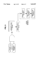
FIG. 1: Lateral View showing a patient handling system at each of two apertures of a primary field magnet.
FIG. 2: A plan view of a primary field magnet having four apertures with a patient handling system proximate each aperture.
FIG. 3: The field of view of a sagittal image obtained during simultaneous magnetic resonance imaging procedures on two patients, along with fiducial markers.
FIG. 4a, 4b: Individual images resulting from the separation and reorientation of image data obtained during simultaneous magnetic resonance imaging procedures on two patients.
FIG. 5: Flow Chart showing an automatic patient transfer sequence.
FIG. 6: Cross-sectional view of patient placed on a breast cushion.
FIG. 7: Cross-sectional view of another embodiment of a breast cushion and radio frequency coil for use in breast region imaging.
FIG. 8: Side view of another embodiment a radio frequency coil according to the invention for use in breast region imaging.
FIG. 9: Lateral view of a patient placed on a breast cushion.
FIG. 10: A plan view of a primary field magnet configured for multiple patient breast region imaging.
DETAILED DESCRIPTION OF THE PREFERRED EMBODIMENTS
A nuclear magnetic resonance scanner generally is comprised of several major subsystems including the primary field magnet, gradient magnetic field subsystem, nuclear magnetic resonance spectrometer, image reconstruction and display subsystem, patient handling subsystems, and radio frequency subsystem. The present invention is concerned with the primary field magnet, the radio frequency subsystem, and the patient handling subsystem, and generally relates to scanning apparatuses and methods which employ multiple, i.e. at least two, patient handling systems, each one capable of positioning a patient in the imaging volume in preparation for a magnetic resonance scan protocol. The scan protocol of a magnetic resonance imaging procedure is carried out on individual patients or on more than one patient simultaneously. For the purposes of this discussion, the gradient magnetic field subsystem is correctly and permanently situated with respect to the primary magnetic field magnet and thus positioning a patient in the imaging volume of the primary field magnet will automatically position the patient with respect to the gradient magnetic field as well.
As shown in FIG. 1, a magnetic resonance scanner having a magnet 1 for generating the primary magnetic field contains two apertures 2 which are opposed to each other. The apertures 2 provide access to an imaging volume 3, where the requisite primary and gradient magnetic fields necessary to conduct a magnetic resonance scan protocol are generated. Also included in the imaging volume 3 are the radio frequency antennas 4 which will be used to stimulate, and receive signal from, the nuclei participating in the nuclear magnetic resonance response.
FIG. 1 also shows two patient handling systems 5, where each one is positioned to provide access to the imaging volume through one of the two opposed apertures 2 in the primary magnet 1. Each patient handling system is comprised of a base support structure 6 and a movable bed structure 7 upon which the patient lies. The movable bed structure 7 provides a means for moving the patient from outside the primary magnet 1, into and out of the imaging volume 3, and also provides a means for the precise positioning of the anatomical region of interest of the patient (8a, 8b) in the imaging volume 3.
A second embodiment of the present invention is illustrated in FIG. 2. The top plate 10 of an iron core magnet is connected to a bottom plate (not shown) of the same size, shape and orientation by a set of four vertical support columns 15, each one of which connects at one of the four protrusions 11 of the top plate of the magnet structure and a corresponding protrusion on the bottom plate of the magnet structure (not shown). The top plate 10 and bottom plate of the magnet are aligned such that the interconnecting support columns are vertical, and parallel with each other.
Such a magnet structure will contain an imaging volume 12 with access provided through as many as four apertures 13, one each between adjacent support columns which join the top and bottom horizontal plates of the magnet. Each aperture is accessed with a patient handling system (14a, 14b, 14c, 14d), thus providing the capability of processing as many as four patients simultaneously. This results in greatly enhancing the throughput of the magnetic resonance scanner.
The apparatuses which are illustrated in FIG. 1 and FIG. 2 of the present invention may be employed to practice the method according to the present invention.
One example of this, using the apparatus shown in FIG. 1, is a method which comprises subjecting one patient (for example 8a) to the scan protocol time component of a magnetic resonance imaging procedure after positioning the patient in the imaging volume, and simultaneously preparing the second patient 8b, for the scan protocol time component of a second magnetic resonance imaging procedure. This overlapping of scan protocol and patient handling functions using two patient handling systems results in a significant enhancement of scanner utilization.
Another method of the present invention is illustrated using the apparatus shown in FIG. 1. Here, each of two patients (8a, 8b), laying on their respective movable bed structure 7 of the patient handling systems 5, is translated through the aperture and positioned in the imaging volume in such a manner as necessary to perform an MR scan protocol of the head region of both patients simultaneously. In general, proper positioning involves placing the anatomical region of interest of each patient at a particular location in the primary magnetic field imaging volume 3 and having the radio frequency antennas 4, positioned in close proximity to the patient's anatomical region of interest.
Radio frequency antenna systems used in magnetic resonance imaging exist as a combination of single mode antennas, in which case each antenna will serve either as a transmitter or receiver of radio frequency energy. Alternatively, antennas may be designed to function in both a transit and receive mode, consequently requiring only a single antenna to conduct an MR scan protocol. Implementation of the radio frequency antennas, whether operated in a single mode as an antenna system or dual mode may occur by having the antenna(s) in a fixed location in the imaging volume. In this instance, a patient is moved into the imaging volume 3 by means of the movable bed structure 7 and proper positioning is achieved simply by positioning the patient such that the anatomical region of interest which is the subject of the MR imaging procedure occupies a place in the imaging volume which has the requisite magnetic field uniformity and radio frequency antenna radiation patterns. Alternatively, the transmitter coil, receiver coil, or dual mode transmitter/receiver coil may be positioned relative to the anatomical region of interest of the patient prior to movement of the patient into the imaging volume 3 by the movable bed structure 7.
Positioned inside the primary magnet and proximate the imaging volume 3 are the radio frequency antennas 4 whose radiation pattern extends over a portion of the imaging volume large enough to cover the head region of two patients (8a, 8b). The head region of each patient is positioned in opposite ends of the receiver coil structure, at which point the MR scan protocol may proceed.
It should be appreciated that the same method may be practiced on an apparatus with more than two patient handling systems. Thus, still another embodiment of the method according to the invention involves four patients (FIG. 2) where each patient (16a, 16b, 16c, 16d) is laying on one of the four patient handling systems 14a, 14b, 14c, 14d respectively, each of which provides access to the imaging volume 12. Two of the patients (16a, 16b) are moved into the imaging volume 12, in the process properly positioning the anatomical region of interest of each patient with respect to the primary magnetic field, and the radio frequency antennas. At this point, an MR scan protocol may commence. As the acquisition of MR imaging data proceeds, preparation of an alternate pair of patients (16c, 16d) for a subsequent scan protocol with each one laying on one of the two remaining patient handling systems, may proceed. At such time as the imaging procedure on the first pair of patients is completed, they may be removed from the imaging volume, followed by placement of the alternate pair of patients (16c, 16d) into the imaging volume to conduct another scan protocol. The procedure of sequential scanning and preparation of alternate pairs of patients is repeated. Alternatively, the apparatus in FIG. 2 may be used to scan patients individually rather than in pairs.
The simultaneous scanning of more than one patient has been described for purposes of illustration in terms of opposed patients on a magnetic resonance scanning system having a magnet with four apertures, and with each aperture being accessed by a patient handling system. This embodiment is not meant to be restricted to the use of opposed patients. Thus, adjacent patients may also be scanned simultaneously. Generalizing this to a system containing a multiplicity off apertures and a multiplicity of patient handling systems, simultaneous scan protocols performed on any number of patients, regardless of their spatial relationships with respect to their position in the imaging volume, is considered to be within the scope of the present invention.
The scan protocol which is part of the magnetic resonance imaging procedure is generally comprised of a pulse sequence designed to yield spatially encoded imaging data, which, when appropriately processed, yields diagnostically important information. In methods involving acquisition of such imaging data from an individual patient, the scan protocol typically involves executing a single pulse sequence, or series of pulse sequences. In the methods according to the present invention involving acquisition of such imaging data from two or more patients simultaneously, a scan protocol can acquire imaging data from a pulse sequence or series of pulse sequences as follows: (a) in queue mode, from each patient successively; (b) in interleaved mode, where each portion of the entire data acquisition contains imaging data from only one of multiple patients, and where the separate portions of the entire data acquisition are collected in interleaved fashion; (c) in multipatient mode, where each portion of the entire data acquisition contains imaging data from more than one patient; (d) or in any combination of queue mode, interleaved mode and multipatient mode of data acquisition.
In the case of multipatient mode scanning of more than one patient, where magnetic resonance imaging data from more than one patient would be contained in individual images, it is necessary to provide means for separation of image data such that data collected for each patient may be diagnosed and archived separately.
In FIG. 3 fiducial markers 20 are small amounts of material which are capable of generating a magnetic resonance signal, and which, when placed in known positions in the imaging volume of the primary magnetic field, serve to mark a specific location in the field of view of an image, which is obtained during a magnetic resonance imaging procedure. As an example of how fiducial markers may be used, consider the case of a magnetic resonance scan protocol conducted in multipatient mode on the head regions of two patients where the scan protocol is performed using a sagittal orientation. The field of view of the resultant images will contain image data as shown in FIG. 3. These data are represented as two distinct and separable sagittal head images 21 and 22. Fiducial markers 20 appear in the field of view of the final image at fixed positions. Such positions are chosen to demarcate the effective boundaries in the imaging volume for each patient.
The NMR response of the fiducial markers may be used as a basis to separate the image data for the two patients. Processing of the image data therefore involves recognition of these fiducial markers on the basis of their NMR response, and the separation, and reorientation of the distinct data sets, consistent with the patient positioning during the acquisition of the data. Thus, the image data shown in FIG. 3 may be separated along a vertical demarcation line 18. The left data set is then rotated 90° counterclockwise; and the right data set is rotated clockwise 90°, and subsequently reversed with respect to left and right. The result of these operations is two separated images, 23 and 24 in FIG. 4a, and FIG. 4b, each from a different patient and represented in a standardized orientation for subsequent diagnosis. It should be apparent that, with the proper incorporation of fiducial markers into the scanning procedure, the process described for separation of images related to different patients may be generalized for any number of patients and yield scans with any desired orientation.
Alternative methods may also be used to separate the image data for multiple patients from a single image. These include using non-signal producing zones in the field of view of an image as a means of demarcation. Such methods are also within the scope of the present invention.
In addition to the gains in patient throughput which result from implementation of the embodiments as already detailed, further improvement will be realized through automation of the switching from the patient handling component to the scan protocol component of the magnetic resonance imaging procedure. This is illustrated in FIG. 5, and is accomplished as follows: During the scan protocol on one patient, a second patient is prepared to undergo a scan protocol on a second patient handling system. When preparation is complete, the second patient will be ready to undergo a scan protocol, which cannot commence until the scan protocol on the first patient is completed. This ready state for the second patient is relayed electronically by the operator, who has prepared the second patient for the scan protocol, to an automatic patient transfer control system. The ready state signal will allow an automatic patient transfer sequence to follow completion of the scan protocol on the first patient. Such a sequence includes removal of the first patient from the imaging volume, placement of the second patient in the imaging volume, and initiation of the scan protocol on the second patient. This automatic patient transfer sequence is accomplished without scanner operator intervention, and is initiated by a logical AND, i.e., by the existence of two signals in the control system. One signal indicates that a patient not presently being subjected to a scan protocol is ready to be scanned, and the second signal indicates the scan protocol on the patient presently in the imaging volume has been completed. This second signal will be generated by the subsystem responsible for control of the scan protocol. Alternatively, the second signal may be set at some time after the scan protocol ends.
Execution of an automatic patient transfer sequence also requires activating the sequential movement of the patient bed structures by a signal from the automatic patient transfer control system. The placement of a patient in, and the removal of a patient from, the imaging volume is accomplished by activating and deactivating a motor which is attached to the patient bed structure of each patient handling system.
The automatic patient transfer control system is comprised of digitally programmable electronics which are part of the standard magnetic resonance scanning apparatus. Programming the control system will enable it to process input signals, generate control signals, and sequence events, all of which are required to execute an automatic patient transfer sequence.
The mode of operation involving an automatic patient transfer sequence may be practiced as related to the embodiment of this invention where single patients are being subjected to a scan protocol, as well as the embodiments involving simultaneous scanning of more than one patient. In the latter case, a ready mode signal and scan completed signal will be generated for more than one patient, and the sequential movement of the patient bed structures will be conducted on two or more beds. It should be clear that patients may also be manually advanced by an operator upon receiving the control signals.
Other embodiments of this invention are illustrated below for the case of breast imaging. In FIG. 6 is shown a cross-sectional view of a patient at the level of the breasts, as positioned for an MRI procedure. In a preferred embodiment, a breast positioning device here in the form of a breast cushion 30 contains two adjacent wells 31a and 31b to accommodate the left breast and the right breast, respectively. The wells 31a and 31b in the breast cushion are defined by its lateral ends 32, and a central protrusion 33, which is common to both the wells 31a and 31b. The breast cushion serves to position and comfortably support the breasts with the patient lying in a prone position. In addition, the central protrusion 33 aids in having the radio frequency antenna conform to the shape of the breasts and chest wall area of the patient, thereby providing optimal positioning of the antenna for a more uniform sampling of imaging data on the entire breast region. However, as an alternative embodiment the breast cushion 30 is also effective as a positioning device for a patient's breast in the absence of the central protrusion 33. In this case a cavity results, which is a continuous region formed by merging the wells 31a and 31b. Such an alternative still provides adequate support for the breast region of a patient.
FIG. 6 also shows the radio frequency antenna 34, positioned between the patient 35, and the breast cushion 30 which is placed on the movable bed structure 7. Rapid and reproducible positioning of the breast cushion 30 on the movable bed structure 7 is achieved by placing the breast cushion 30 between the alignment tabs 38 which are secured to the movable bed structure 7. The alignment tabs 38 are periodically placed along the sides of the movable bed structure 7 to provide alignment along the length of the breast cushion. Once the breast cushion 30 is aligned on the movable bed structure 7, it is held firmly in place by a number of velcro (Trademark)-like attachments 39, which run the length of the movable bed structure 7 and the breast cushion 30. Such a fastening approach facilitates rapid and reversible placement of the breast cushion 30.
In a preferred embodiment, the radio frequency antenna 34 is configured as a highly flexible elongate conductor strip which can be wrapped around the patient much like a belt. Mechanical and electrical closure of the strip is completed at some convenient accessible location, 36. The flexible, body conforming aspect of the elongate conductor strip is conferred on this antenna by employing a cloth-like material, such as comprising fiberglass, together with flexible copper. Other materials with similar mechanical and electrical characteristics may be substituted. The highly flexible nature of the antenna 34 helps to insure conformity to the patient's anatomy.
An alternative embodiment of the radio frequency antenna system which optimizes the magnetic resonance imaging procedure as related to the breast region is shown in FIG. 7. Many of the elements in FIG. 7 are the same as shown and described in FIG. 6, except for the positioning of the radio frequency antenna 34. In FIG. 7, the radio frequency antenna 34, is placed in close proximity to, and closely follows, the contour of the breast cushion 32. Thus in this alternative embodiment the shape of the radio frequency antenna is more directly correlated with the scope of the wells 31a and 31b, than the actual shape and size of the breasts of the patient, as shown in FIG. 6.
It is to be appreciated that the prone position of the patient is considered optimal for breast imaging since pendulous breasts enhance the quality of diagnostic imaging. Furthermore, the prone position of the patient suppresses motion artifacts caused by movement of the chest wall with respiration. However, imaging of the breast region of a patient can also be achieved with the patient in a supine position, or lying on side. Also other forms of a breast positioning device may be employed instead of a breast cushion. For example, the breast positioning device may be incorporated as a permanent or semi-permanent part of the movable bed structure; or the breast positioning device might become an integral part of a radio frequency antenna system in order to facilitate breast imaging in patient positions other than prone.
An example of this latter embodiment is shown in FIG. 8 which shows radio frequency antenna 40 with two portions. A lower portion 42 of the radio frequency antenna 40 is rigidized structurally so as to maintain a shape similar to and complementary with the breast region of a patient, independent of external shaping means. The rigidizing properties may be achieved by various means. One such means is by casting or coating the lower portion 42 of the radio frequency antenna 40 with an epoxy-like material when the radio frequency antenna 40 has the desired shape. Once the epoxy-like material cures, the desired shape will become a permanent structural feature of the radio frequency antenna 40. Alternatively, a rigid plastic sleeve, which has the desired shape of the breast region of the body, may be placed around the lower portion 42 of the radio frequency antenna 40 in order to provide a rigid shape independent of external shaping means. Materials other than plastic which are capable of providing rigid structure may also be used.
The upper portion 41 of the radio frequency antenna 40 shown in FIG. 8 is flexible and surrounds the torso of a patient once positioned in the lower portion 42. Electrical and mechanical closure of the antenna 40 is accomplished by joining at 43.
Other designs for the radio frequency antennas may also be appropriate as related to placing of a patient in a position other than prone. For example, positioning a patient on side represents a placement of the breasts in a position suited for radio frequency antennas of a solenoidal or saddle shape geometry. Furthermore, as described above, the radio frequency antenna may function in single mode as a transmitter or a receiver, or in dual mode as both a transmitter and a receiver.
A lateral view of a patient 35, lying in a prone position, lying on the breast cushion 30 in preparation for an MRI procedure is shown in FIG. 9. The patients breast 37a is essentially pendulous inside the well 31a of the breast cushion, with the radio frequency antenna 34 wrapped around the patient at the level of the breasts.
In the case of a magnet having four apertures and four associated patient handling systems as shown in FIG. 10, each patient handling system has an associated breast cushion 30 capable of accepting a patient for imaging of the breast region. FIG. 10 thus represents a high throughput embodiment of the present invention. It should be clear that enhanced throughput also results from alternative configurations which contain two or three patient handling systems.
The acquisition of diagnostic breast imaging information can then proceed according to the procedures detailed above. Thus, in the case of a primary field magnet with at least two apertures and at least two associated patient handling systems, patients to be subjected to a breast imaging procedure may be scanned individually or in multiple fashion by the simultaneous scanning of more than one patient. In either case, the overlapping of the scan protocol time component, and the patient handling time component will improve the utilization of magnetic resonance scanners for breast imaging.
Also, implementation of an automatic patient transfer sequence as shown in FIG. 5 in conjunction with the breast scanning embodiments of the invention provides additional improvement in the utilization of magnetic resonance scanners.

Claims (32)

We claim:
1. A medical magnet resonance imaging system comprising:
(a) a magnet having an imaging volume and at least two apertures, wherein each aperture is sufficiently large to provide patient access to the imaging volume;
(b) at least two patient handling systems, with each of said patient handling systems comprising a moveable bed structure having means which provides access to one of said apertures of said magnet and with each of said moveable bed structures having means for receiving and positioning the breast region of a patient to be subjected to a magnetic resonance imaging procedure in said imaging volume of said magnet;
(c) a radio frequency antenna system for transmitting radio frequency energy into a patient and detecting magnetic resonance imaging data from said breast region of each said patient.
2. An apparatus as described in claim 1, wherein said radio frequency antenna system comprises a body conforming receiving antenna.
3. An apparatus as described in claim 2, wherein said body conforming receiving antenna is structurally comprised of a flexible cloth-like material.
4. An apparatus as described in claim 3, wherein said receiving antenna further comprises electrical elements comprised of flexible copper strips.
5. An apparatus as in claim 3, wherein said flexible cloth-like material is comprised of fiberglass.
6. An apparatus as described in claim 1, wherein said antenna system comprises a single radio frequency antenna to transmit and to receive radio frequency energy.
7. An apparatus as described in claim 1, further comprising a breast positioning device for positioning the breasts of said patient.
8. An apparatus as described in claim 7, wherein said breast positioning device comprises a cushion containing a contoured recess for positioning said patient's breasts.
9. An apparatus as in claim 8, wherein said breast cushion contains a separate well to position each of said breasts.
10. An apparatus as described in claim 8, further comprising means for releasably attaching said breast cushion to said movable bed to permit removal of said breast cushion to facilitate magnetic resonance imaging of other regions of a patient than the breast region.
11. An apparatus as described in claim 1, wherein said magnet has at least three apertures.
12. An apparatus as described in claim 1, having at least three patient handling systems.
13. An apparatus as described in claim 1, wherein said magnet has four apertures.
14. An apparatus as described in claim 1, having four patient handling systems.
15. An apparatus as described in claim 1, wherein said patient handling systems are independent of one another to permit sequential breast imaging of two patients with each said patient utilizing a different one of said patient handling systems to gain access to a different one of said apertures of said magnet.
16. An apparatus as described in claim 1, wherein said patient handling systems are independent of one another to permit sequential breast imaging of multiple patients with each said patient utilizing a different one of said multiple patient handling systems to gain access to a different one of said apertures of said magnet.
17. An apparatus as described in claim 1, wherein said patient handling systems comprise motorized patient bed structures capable of remotely controlled operation.
18. A medical magnetic resonance imaging system comprising:
(a) a magnet having an imaging volume and at least two apertures where each aperture is sufficiently large to provide patient access to the imaging volume;
(b) at least two patient handling systems each comprising a moveable bed structure having means which provides access to one of said apertures of said magnet, and at least two of said moveable bed structures each having means for receiving and positioning the breast region of a patient to be subjected to a magnetic resonance imaging procedure, wherein said means for receiving and positioning of each of said at least two moveable bed structures can be within said imaging volume of said magnet at the same time;
(c) a radio frequency antenna system for transmitting radio frequency energy into each said patient and simultaneously detecting magnetic resonance imaging data from said breast region of each said patient; and
(d) means for demarcating and separating said magnetic resonance imaging data into separate images corresponding to said breast region for each said patient.
19. An apparatus as described in claim 18, wherein said radio frequency antenna system comprises a body conforming receiving antenna.
20. An apparatus as described in claim 19, wherein said body conforming receiving antenna is structurally comprised of a flexible cloth-like material.
21. An apparatus as described in claim 20, wherein said receiving antenna further comprises electrical elements comprised of flexible copper strips.
22. An apparatus as in claim 20, wherein said flexible cloth-like material is comprised of fiberglass.
23. An apparatus as described in claim 20, wherein said antenna system comprises a single radio frequency antenna to transmit and to receive radio frequency energy.
24. An apparatus as described in claim 20, further comprising a breast positioning device for positioning the breasts of said patient.
25. An apparatus as described in claim 24, wherein said breast positioning device comprises a cushion containing a contoured recess for positioning said patient's breasts.
26. An apparatus as in claim 25, wherein said breast cushion contains a separate well to position each of said breasts.
27. An apparatus as described in claim 25, further comprising means for releasably attaching said breast cushion to said movable bed to permit removal of said breast cushion to facilitate magnetic resonance imaging of other regions of a patient than the breast region.
28. An apparatus as described in claim 18, wherein said magnet has at least three apertures.
29. An apparatus as described in claim 18, having three patient handling systems.
30. An apparatus as described in claim 18, wherein said magnet has four apertures.
31. An apparatus as described in claim 18, having four patient handling systems.
32. An apparatus as described in claim 18, wherein said patient handling systems comprise motorized patient bed structures capable of remotely controlled operation.
US08/456,508 1992-09-28 1995-06-01 Multiple patient breast scanning on a magnetic resonance imaging apparatus Expired - Lifetime US5623927A (en)

Priority Applications (1)

Application Number Priority Date Filing Date Title
US08/456,508 US5623927A (en) 1992-09-28 1995-06-01 Multiple patient breast scanning on a magnetic resonance imaging apparatus

Applications Claiming Priority (3)

Application Number Priority Date Filing Date Title
US07/952,327 US5606970A (en) 1992-09-28 1992-09-28 Multiple patient scanning on a magnetic resonance imaging apparatus
US08/131,124 US5490513A (en) 1992-09-28 1993-10-04 Multiple patient breast scanning on a magnetic resonance imaging apparatus
US08/456,508 US5623927A (en) 1992-09-28 1995-06-01 Multiple patient breast scanning on a magnetic resonance imaging apparatus

Related Parent Applications (1)

Application Number Title Priority Date Filing Date
US08/131,124 Continuation US5490513A (en) 1992-09-28 1993-10-04 Multiple patient breast scanning on a magnetic resonance imaging apparatus

Publications (1)

Publication Number Publication Date
US5623927A true US5623927A (en) 1997-04-29

Family

ID=26829160

Family Applications (3)

Application Number Title Priority Date Filing Date
US08/131,124 Expired - Lifetime US5490513A (en) 1992-09-28 1993-10-04 Multiple patient breast scanning on a magnetic resonance imaging apparatus
US08/456,508 Expired - Lifetime US5623927A (en) 1992-09-28 1995-06-01 Multiple patient breast scanning on a magnetic resonance imaging apparatus
US08/456,703 Expired - Lifetime US5664569A (en) 1992-09-28 1995-06-01 Breast positioning device for use during magnetic resonance imaging

Family Applications Before (1)

Application Number Title Priority Date Filing Date
US08/131,124 Expired - Lifetime US5490513A (en) 1992-09-28 1993-10-04 Multiple patient breast scanning on a magnetic resonance imaging apparatus

Family Applications After (1)

Application Number Title Priority Date Filing Date
US08/456,703 Expired - Lifetime US5664569A (en) 1992-09-28 1995-06-01 Breast positioning device for use during magnetic resonance imaging

Country Status (1)

Country Link
US (3) US5490513A (en)

Cited By (15)

* Cited by examiner, † Cited by third party
Publication number Priority date Publication date Assignee Title
US6023166A (en) * 1997-11-19 2000-02-08 Fonar Corporation MRI antenna
US6195578B1 (en) * 1999-01-14 2001-02-27 Siemens Aktiengesellschaft Magnetic resonance apparatus for intraoperative imaging
US20030128033A1 (en) * 2001-11-15 2003-07-10 Ralph Sinkus Mammography accessory for MR elastography
EP1424039A1 (en) * 2002-11-28 2004-06-02 Esaote S.p.A. Combination magnetic resonance imaging apparatus and patient table
US20050020898A1 (en) * 2003-07-10 2005-01-27 Vosniak Kenneth J. System and method for configuring a scanning procedure
US20050187459A1 (en) * 2004-02-02 2005-08-25 Esaote, S.P.A. Magnetic resonance imaging apparatus
US20080106262A1 (en) * 2006-06-08 2008-05-08 Kabushiki Kaisha Toshiba Magnetic resonance imaging apparatus
EP2437077A1 (en) 2010-09-30 2012-04-04 Aspect Magnet Technologies Ltd. An MRI device with a plurality of individually controllable entry ports and inserts therefor
CN103800027A (en) * 2012-11-14 2014-05-21 上海联影医疗科技有限公司 Positron emission computed tomography scanning method and system
EP2623027A4 (en) * 2010-09-30 2015-07-29 Hitachi Medical Corp Magnetic resonance imaging device
CN106725579A (en) * 2016-12-28 2017-05-31 上海联影医疗科技有限公司 Medical Devices
CN109171030A (en) * 2018-09-21 2019-01-11 川田卫生用品(浙江)有限公司 The flexible Ru Dian mechanism to absorb water by force
US10292617B2 (en) 2010-09-30 2019-05-21 Aspect Imaging Ltd. Automated tuning and frequency matching with motor movement of RF coil in a magnetic resonance laboratory animal handling system
US11340321B2 (en) * 2019-05-09 2022-05-24 Siemens Healthcare Gmbh Magnetic resonance tomography system
US11454686B2 (en) * 2019-11-27 2022-09-27 Siemens Healthcare Gmbh Gradient system for a magnetic resonance imaging system

Families Citing this family (54)

* Cited by examiner, † Cited by third party
Publication number Priority date Publication date Assignee Title
US5490513A (en) * 1992-09-28 1996-02-13 Fonar Corporation Multiple patient breast scanning on a magnetic resonance imaging apparatus
US6023165A (en) * 1992-09-28 2000-02-08 Fonar Corporation Nuclear magnetic resonance apparatus and methods of use and facilities for incorporating the same
US6201394B1 (en) 1992-12-18 2001-03-13 Fonar Corporation MRI apparatus
US6335623B1 (en) 1992-12-18 2002-01-01 Fonar Corporation MRI apparatus
JP3368287B2 (en) * 1996-05-23 2003-01-20 学校法人金沢工業大学 Magnetic measuring device
US6028429A (en) * 1996-07-17 2000-02-22 Fonar Corporation Composite MRI antenna with reduced stray capacitance
US5939883A (en) * 1996-07-17 1999-08-17 Fonar Corporation Magnetic resonance imaging excitation and reception methods and apparatus
US5851182A (en) * 1996-09-11 1998-12-22 Sahadevan; Velayudhan Megavoltage radiation therapy machine combined to diagnostic imaging devices for cost efficient conventional and 3D conformal radiation therapy with on-line Isodose port and diagnostic radiology
US5842987A (en) * 1997-05-20 1998-12-01 Sahadevan; Velayudhan Simulated patient setup for medical imaging with increased patient throughput
GB2325979A (en) * 1997-06-04 1998-12-09 Marconi Gec Ltd Cylindrical MRI magnet with additional sensing volumes using the return flux
US6437571B1 (en) 1997-11-21 2002-08-20 Fonar Corporation MRI apparatus
US7127802B1 (en) 1997-11-21 2006-10-31 Fonar Corporation Method of fabricating a composite plate
US6198957B1 (en) 1997-12-19 2001-03-06 Varian, Inc. Radiotherapy machine including magnetic resonance imaging system
US6889073B2 (en) * 2000-05-08 2005-05-03 David A. Lampman Breast biopsy and therapy system for magnetic resonance imagers
US7196519B2 (en) * 2000-07-28 2007-03-27 Fonar Corporation Stand-up vertical field MRI apparatus
US8190234B2 (en) 2000-07-28 2012-05-29 Fonar Corporation Movable patient support with spatial locating feature
US7697971B1 (en) 2000-07-28 2010-04-13 Fonar Corporation Positioning system for an MRI
US6822449B1 (en) 2000-11-22 2004-11-23 Fonar Corporation Ferromagnetic frame with laminated carbon steel
US6934574B1 (en) 2001-06-21 2005-08-23 Fonar Corporation MRI scanner and method for modular patient handling
US6944492B1 (en) 2001-10-01 2005-09-13 Fonar Corporation Patient bed support for an open MRI system
US7701209B1 (en) 2001-10-05 2010-04-20 Fonar Corporation Coils for horizontal field magnetic resonance imaging
US7906966B1 (en) 2001-10-05 2011-03-15 Fonar Corporation Quadrature foot coil antenna for magnetic resonance imaging
US8036730B1 (en) 2002-04-19 2011-10-11 Fonar Corporation Temporal magnetic resonance imaging
US7123008B1 (en) 2002-04-19 2006-10-17 Fonar Corporation Positional magnetic resonance imaging
AU2003294458A1 (en) * 2002-11-25 2004-06-18 Fonar Corporation Method, apparatus, and facility for mri dual scanning
US8064984B2 (en) 2003-03-18 2011-11-22 Esaote S.P.A. Magnetic resonance imaging apparatus
US7378846B1 (en) * 2004-06-29 2008-05-27 Fonar Corporation Magnetic resonance imaging method and apparatus for scanning a child
US8401615B1 (en) 2004-11-12 2013-03-19 Fonar Corporation Planar coil flexion fixture for magnetic resonance imaging and use thereof
AU2006256434B2 (en) * 2005-06-09 2012-04-05 Aspect Magnet Technologies Ltd. A portable quality and process control system for simultaneous magnetic resonance imaging of multiple samples
US7880467B2 (en) * 2005-06-09 2011-02-01 Aspect Magnet Technologies Ltd. Packed array of MRI/NMR devices and an MRI/NMR method of analyzing adjacent lines of goods simultaneously
US7515951B2 (en) * 2005-06-23 2009-04-07 International Business Machines Corporation Assembly, system, and method for optimizing image quality
US7400147B2 (en) * 2005-11-03 2008-07-15 Uri Rapoport Self-fastening cage surrounding a magnetic resonance device and methods thereof
US20090274353A1 (en) * 2006-04-13 2009-11-05 Koninklijke Philips Electronics N. V. Background magnetic resonance imaging
EP2034889B1 (en) * 2006-06-20 2020-08-05 IMRIS Inc. Rotatable mri scanner for diagnostic and surgical imaging applications
US9386939B1 (en) 2007-05-10 2016-07-12 Fonar Corporation Magnetic resonance imaging of the spine to detect scoliosis
US20090124888A1 (en) * 2007-11-14 2009-05-14 Hitachi Medical Systems America, Inc. Wing Design for RF Coil for MRI Imaging
US8599215B1 (en) 2008-05-07 2013-12-03 Fonar Corporation Method, apparatus and system for joining image volume data
EP2168485A1 (en) * 2008-09-29 2010-03-31 MIR Medical Imaging Research Holding GmbH Breast holder for examination device for examination of breasts
US20100128843A1 (en) * 2008-11-22 2010-05-27 Mir Medical Imaging Research Holding Gmbh Device for Locating a Female Breast for Diagnostic Imaging and Intervention
WO2011001429A1 (en) 2009-06-30 2011-01-06 Aspect Magnet Technologies Ltd. A cage in an mrd with a fastening/attenuating system
US11278461B2 (en) 2010-07-07 2022-03-22 Aspect Imaging Ltd. Devices and methods for a neonate incubator, capsule and cart
US10076266B2 (en) 2010-07-07 2018-09-18 Aspect Imaging Ltd. Devices and methods for a neonate incubator, capsule and cart
DE102012212692B4 (en) * 2012-07-19 2023-03-23 Siemens Healthcare Gmbh Local coil system, local coil for a local coil system, magnetic resonance imaging system, method for controlling and/or regulating the pressure of a local coil relative to an examination subject and method for generating magnetic resonance images
US9766310B1 (en) 2013-03-13 2017-09-19 Fonar Corporation Method and apparatus for magnetic resonance imaging of the cranio-cervical junction
US11300531B2 (en) 2014-06-25 2022-04-12 Aspect Ai Ltd. Accurate water cut measurement
US10224135B2 (en) 2016-08-08 2019-03-05 Aspect Imaging Ltd. Device, system and method for obtaining a magnetic measurement with permanent magnets
US11287497B2 (en) 2016-08-08 2022-03-29 Aspect Imaging Ltd. Device, system and method for obtaining a magnetic measurement with permanent magnets
US10345251B2 (en) 2017-02-23 2019-07-09 Aspect Imaging Ltd. Portable NMR device for detecting an oil concentration in water
US10847294B2 (en) 2017-07-10 2020-11-24 Aspect Imaging Ltd. System for generating a magnetic field
CN108542394A (en) * 2018-04-16 2018-09-18 中国科学技术大学 A kind of mammary contour measurement method and device based on Kinect
EP3736591A1 (en) * 2019-05-09 2020-11-11 Siemens Healthcare GmbH Base field magnet assembly for an mrt system
EP3839541A3 (en) * 2019-11-27 2021-10-06 Siemens Healthcare GmbH Toroidal magnet configuration for dedicated mri scanners
USD951274S1 (en) * 2020-12-30 2022-05-10 Varian Medical Systems, Inc. Display screen of an electronic device with a graphical user interface
JP2022158004A (en) * 2021-04-01 2022-10-14 キヤノンメディカルシステムズ株式会社 magnetic resonance imaging system

Citations (14)

* Cited by examiner, † Cited by third party
Publication number Priority date Publication date Assignee Title
DE3140225A1 (en) * 1981-10-09 1983-04-28 Siemens AG, 1000 Berlin und 8000 München Device for generating images of an object under examination
US4608991A (en) * 1984-09-26 1986-09-02 Southwest Research Institute Method for in-vivo NMR measurements in the human breast to screen for small breast cancer in an otherwise healthy breast
US4629989A (en) * 1983-11-10 1986-12-16 General Electric Company Patient alignment system for NMR studies
US4644275A (en) * 1984-01-20 1987-02-17 Picker International Limited Nuclear magnetic resonance apparatus
US4668915A (en) * 1985-03-15 1987-05-26 Honda Giken Kogyo Kabushiki Kaisha Non-uniform field magnetic resonance dual patient imaging system
US4691163A (en) * 1985-03-19 1987-09-01 Elscint Ltd. Dual frequency surface probes
US4770182A (en) * 1986-11-26 1988-09-13 Fonar Corporation NMR screening method
US4885540A (en) * 1988-10-31 1989-12-05 Amoco Corporation Automated nuclear magnetic resonance analysis
US4920318A (en) * 1985-08-14 1990-04-24 Picker International, Inc. Surface coil system for magnetic resonance imaging
US5024229A (en) * 1987-11-16 1991-06-18 The University Of Rochester Resonators for magnetic resonance imaging
JPH04332531A (en) * 1991-05-08 1992-11-19 Hitachi Ltd Inspecting device using nuclear magnetic resonance
US5197474A (en) * 1990-06-14 1993-03-30 Instrumentarium Corp. Patient bed in a magnetic resonance imaging apparatus
US5416413A (en) * 1992-08-13 1995-05-16 U. S. Philips Corporation Magnetic resonance examination apparatus comprising a coil system for MR mammography
US5490513A (en) * 1992-09-28 1996-02-13 Fonar Corporation Multiple patient breast scanning on a magnetic resonance imaging apparatus

Patent Citations (14)

* Cited by examiner, † Cited by third party
Publication number Priority date Publication date Assignee Title
DE3140225A1 (en) * 1981-10-09 1983-04-28 Siemens AG, 1000 Berlin und 8000 München Device for generating images of an object under examination
US4629989A (en) * 1983-11-10 1986-12-16 General Electric Company Patient alignment system for NMR studies
US4644275A (en) * 1984-01-20 1987-02-17 Picker International Limited Nuclear magnetic resonance apparatus
US4608991A (en) * 1984-09-26 1986-09-02 Southwest Research Institute Method for in-vivo NMR measurements in the human breast to screen for small breast cancer in an otherwise healthy breast
US4668915A (en) * 1985-03-15 1987-05-26 Honda Giken Kogyo Kabushiki Kaisha Non-uniform field magnetic resonance dual patient imaging system
US4691163A (en) * 1985-03-19 1987-09-01 Elscint Ltd. Dual frequency surface probes
US4920318A (en) * 1985-08-14 1990-04-24 Picker International, Inc. Surface coil system for magnetic resonance imaging
US4770182A (en) * 1986-11-26 1988-09-13 Fonar Corporation NMR screening method
US5024229A (en) * 1987-11-16 1991-06-18 The University Of Rochester Resonators for magnetic resonance imaging
US4885540A (en) * 1988-10-31 1989-12-05 Amoco Corporation Automated nuclear magnetic resonance analysis
US5197474A (en) * 1990-06-14 1993-03-30 Instrumentarium Corp. Patient bed in a magnetic resonance imaging apparatus
JPH04332531A (en) * 1991-05-08 1992-11-19 Hitachi Ltd Inspecting device using nuclear magnetic resonance
US5416413A (en) * 1992-08-13 1995-05-16 U. S. Philips Corporation Magnetic resonance examination apparatus comprising a coil system for MR mammography
US5490513A (en) * 1992-09-28 1996-02-13 Fonar Corporation Multiple patient breast scanning on a magnetic resonance imaging apparatus

Cited By (24)

* Cited by examiner, † Cited by third party
Publication number Priority date Publication date Assignee Title
US6023166A (en) * 1997-11-19 2000-02-08 Fonar Corporation MRI antenna
US6195578B1 (en) * 1999-01-14 2001-02-27 Siemens Aktiengesellschaft Magnetic resonance apparatus for intraoperative imaging
US20030128033A1 (en) * 2001-11-15 2003-07-10 Ralph Sinkus Mammography accessory for MR elastography
US6833703B2 (en) * 2001-11-15 2004-12-21 Koninklijke Philips Electronics N.V. Mechanical oscillator for MR elastography
US7869857B2 (en) 2002-11-28 2011-01-11 Esaote S.P.A. Combination magnetic resonance imaging apparatus and patient table
EP1424039A1 (en) * 2002-11-28 2004-06-02 Esaote S.p.A. Combination magnetic resonance imaging apparatus and patient table
US20040162480A1 (en) * 2002-11-28 2004-08-19 Esaote S.P.A. Combination magnetic resonance imaging apparatus and patient table
US20050020898A1 (en) * 2003-07-10 2005-01-27 Vosniak Kenneth J. System and method for configuring a scanning procedure
US8195273B2 (en) 2004-02-02 2012-06-05 Esaote S.P.A. Magnetic resonance imaging apparatus
US9888865B2 (en) 2004-02-02 2018-02-13 Esaote S.P.A. Magnetic resonance imaging apparatus
US20050187459A1 (en) * 2004-02-02 2005-08-25 Esaote, S.P.A. Magnetic resonance imaging apparatus
US7719271B2 (en) * 2006-06-08 2010-05-18 Kabushiki Kaisha Toshiba RF coil and transmission line handling system for magnetic resonance imaging apparatus
US20080106262A1 (en) * 2006-06-08 2008-05-08 Kabushiki Kaisha Toshiba Magnetic resonance imaging apparatus
EP2840409A1 (en) 2010-09-30 2015-02-25 Aspect Magnet Technologies Ltd. An MRI device with a plurality of individually controllable entry ports and inserts therefor
US8807084B2 (en) 2010-09-30 2014-08-19 Aspect Imaging Ltd. MRI device with a plurality of individually controllable entry ports and inserts therefor
EP2623027A4 (en) * 2010-09-30 2015-07-29 Hitachi Medical Corp Magnetic resonance imaging device
US9681822B2 (en) 2010-09-30 2017-06-20 Aspect Magnet Technologies Ltd. MRI device with a plurality of individually controllable entry ports and inserts therefor
EP2437077A1 (en) 2010-09-30 2012-04-04 Aspect Magnet Technologies Ltd. An MRI device with a plurality of individually controllable entry ports and inserts therefor
US10292617B2 (en) 2010-09-30 2019-05-21 Aspect Imaging Ltd. Automated tuning and frequency matching with motor movement of RF coil in a magnetic resonance laboratory animal handling system
CN103800027A (en) * 2012-11-14 2014-05-21 上海联影医疗科技有限公司 Positron emission computed tomography scanning method and system
CN106725579A (en) * 2016-12-28 2017-05-31 上海联影医疗科技有限公司 Medical Devices
CN109171030A (en) * 2018-09-21 2019-01-11 川田卫生用品(浙江)有限公司 The flexible Ru Dian mechanism to absorb water by force
US11340321B2 (en) * 2019-05-09 2022-05-24 Siemens Healthcare Gmbh Magnetic resonance tomography system
US11454686B2 (en) * 2019-11-27 2022-09-27 Siemens Healthcare Gmbh Gradient system for a magnetic resonance imaging system

Also Published As

Publication number Publication date
US5664569A (en) 1997-09-09
US5490513A (en) 1996-02-13

Similar Documents

Publication Publication Date Title
US5623927A (en) Multiple patient breast scanning on a magnetic resonance imaging apparatus
US5606970A (en) Multiple patient scanning on a magnetic resonance imaging apparatus
US8587311B2 (en) Multi-channel breast MRI radio frequency receiver coil
US4534358A (en) Nuclear magnetic resonance imaging apparatus
US5998999A (en) Volume RF coils with integrated high resolution focus coils for magnetic resonance imaging
US8046046B2 (en) RF array coil system and method for magnetic resonance imaging
US7312610B2 (en) Method for acquiring magnetic resonance data from a large examination region
EP0487201B1 (en) Magnetic resonance imaging apparatus and methods
JP3983170B2 (en) Method for acquiring MRI image using subsampling in vertical magnetic field MRI apparatus
US20070282194A1 (en) Transmit-Receive Array For High Field MRI
US6377836B1 (en) RF coil array for vertical field MRI
US20080275333A1 (en) Local mri breast coil and method of use
US20130076358A1 (en) Adjustable mri head coil apparatus and mri system
CN103814302A (en) Integrated MR imaging and interventional coil device, method and system
US20090082662A1 (en) Mri breast image magnet structure
JP4891539B2 (en) High frequency coil assembly and magnetic resonance imaging apparatus
WO2010027777A2 (en) Method and apparatus for multimodal imaging
JP5575454B2 (en) Magnetic resonance imaging system
EP0955554A2 (en) Multi-frequency magnetic resonance imaging
JP2001198100A (en) Mr data gathering method, mr image display method and mri device
CN107072587A (en) The system and method being imaged for spiral volume
US11448714B2 (en) Multi-planar intraoral RF coil for magnetic resonance imaging
Schenck et al. High-field surface-coil MR imaging of localized anatomy.
JP4031964B2 (en) Receiver coil for magnetic resonance imaging apparatus and apparatus using the same
Artemov et al. Switchable multicoil array for MR micro‐imaging of breast lesions

Legal Events

Date Code Title Description
STCF Information on status: patent grant

Free format text: PATENTED CASE

CC Certificate of correction
REMI Maintenance fee reminder mailed
FPAY Fee payment

Year of fee payment: 4

SULP Surcharge for late payment
FEPP Fee payment procedure

Free format text: PAT HOLDER NO LONGER CLAIMS SMALL ENTITY STATUS, ENTITY STATUS SET TO UNDISCOUNTED (ORIGINAL EVENT CODE: STOL); ENTITY STATUS OF PATENT OWNER: LARGE ENTITY

REFU Refund

Free format text: REFUND - 7.5 YR SURCHARGE - LATE PMT W/IN 6 MO, LARGE ENTITY (ORIGINAL EVENT CODE: R1555); ENTITY STATUS OF PATENT OWNER: LARGE ENTITY

Free format text: REFUND - PAYMENT OF MAINTENANCE FEE, 8TH YEAR, LARGE ENTITY (ORIGINAL EVENT CODE: R1552); ENTITY STATUS OF PATENT OWNER: LARGE ENTITY

Free format text: REFUND - PAYMENT OF MAINTENANCE FEE, 8TH YR, SMALL ENTITY (ORIGINAL EVENT CODE: R2552); ENTITY STATUS OF PATENT OWNER: LARGE ENTITY

FPAY Fee payment

Year of fee payment: 8

SULP Surcharge for late payment

Year of fee payment: 7

REMI Maintenance fee reminder mailed
FPAY Fee payment

Year of fee payment: 12

SULP Surcharge for late payment

Year of fee payment: 11