US5649929A - Knee joint flexion-gap distraction device - Google Patents
Knee joint flexion-gap distraction device Download PDFInfo
- Publication number
- US5649929A US5649929A US08/500,732 US50073295A US5649929A US 5649929 A US5649929 A US 5649929A US 50073295 A US50073295 A US 50073295A US 5649929 A US5649929 A US 5649929A
- Authority
- US
- United States
- Prior art keywords
- femur
- tibial
- knee
- femoral
- cutting guide
- Prior art date
- Legal status (The legal status is an assumption and is not a legal conclusion. Google has not performed a legal analysis and makes no representation as to the accuracy of the status listed.)
- Expired - Lifetime
Links
Images


Classifications
-
- A—HUMAN NECESSITIES
- A61—MEDICAL OR VETERINARY SCIENCE; HYGIENE
- A61B—DIAGNOSIS; SURGERY; IDENTIFICATION
- A61B17/00—Surgical instruments, devices or methods, e.g. tourniquets
- A61B17/02—Surgical instruments, devices or methods, e.g. tourniquets for holding wounds open; Tractors
- A61B17/025—Joint distractors
-
- A—HUMAN NECESSITIES
- A61—MEDICAL OR VETERINARY SCIENCE; HYGIENE
- A61B—DIAGNOSIS; SURGERY; IDENTIFICATION
- A61B17/00—Surgical instruments, devices or methods, e.g. tourniquets
- A61B17/14—Surgical saws ; Accessories therefor
- A61B17/15—Guides therefor
- A61B17/154—Guides therefor for preparing bone for knee prosthesis
- A61B17/155—Cutting femur
-
- A—HUMAN NECESSITIES
- A61—MEDICAL OR VETERINARY SCIENCE; HYGIENE
- A61B—DIAGNOSIS; SURGERY; IDENTIFICATION
- A61B17/00—Surgical instruments, devices or methods, e.g. tourniquets
- A61B17/02—Surgical instruments, devices or methods, e.g. tourniquets for holding wounds open; Tractors
- A61B17/025—Joint distractors
- A61B2017/0268—Joint distractors for the knee
Definitions
- the present invention relates to a knee joint distraction device for facilitating knee arthroplasty, especially total knee arthroplasty.
- knee arthroplasty Primary objectives of knee arthroplasty include restoration of limb alignment, ligament balance, and joint surface contours. Restoration of limb alignment in extension reduces asymmetric loading of the bicondylar design, probably reducing the risk of component loosening. Restoration of ligament balance and joint surface contours prevents instability and restores normal joint kinematics.
- Surgical instrumentation serves to simplify and standardize the implantation procedure.
- Several operative techniques have been advocated, differing in instrumentation and in the sequence of bone cuts.
- the present invention may be usefully employed in any of the several techniques.
- a total knee joint prosthesis typically includes a tibial platform and a femoral component having condyler portions adapted to rest in complementary surfaces of the tibial component.
- Restoration of ligament balance requires careful positioning of these tibial and femoral components and selective lengthening of contracted ligamentous or soft-tissue structures.
- the ligaments should be balanced at every position of knee flexion. To simplify the surgical technique, the ligament balance is checked mainly at full knee extension and at 90° knee flexion.
- both limb alignment and ligament balance must be restored.
- the distal femoral bone cut is made perpendicular to the axis between the centers of the hip and knee joints.
- the proximal tibial cut is made perpendicular to the longitudinal axis of the tibial shaft. Contracted ligaments and soft tissues are then lengthened by partial release as needed to equalize their length and tension in extension. After these bone and soft tissue cuts are made, the gap between distal femoral surface and proximal tibial surface (the extension gap) should accommodate the combined thickness of the tibial and femoral components, with the medial and lateral knee ligaments equally tensioned to provide stability.
- ligament balance in extension has been addressed by the use of either spacer blocks or a joint distraction instrument.
- Spacer blocks are oval, metallic shims of the approximate shape and size of the proximal tibial platform. After proximal tibial and distal femoral cuts are made, spacer blocks of increasing thickness are placed in the extension gap. Gentle medial (valgus) and lateral (varus) stresses are applied to the knee by the surgeon, and the relative lengths and tensions of medial and lateral ligaments are assessed. Incremental releases are performed as needed to balance the ligaments.
- a joint distraction instrument is placed between the distal femoral condyles and the previously cut proximal tibial surface during full knee extension.
- the ligaments are equally tensioned. Partial ligament releases are then performed while maintaining equal ligament tension.
- the distal femoral cut is made parallel to the proximal tibial cut.
- ligament balance can be restored by changing the alignment of the posterior femoral bone cut.
- the tibial cut and soft tissue releases also affect the flexion gap, but these factors are predetermined by the requirements of limb alignment and ligament balance in extension.
- the posterior femoral bone cut has been positioned by posterior condyle referencing or by the use of a joint distraction instrument.
- Posterior condyle referencing involves empirically positioning the posterior femoral cut to remove slightly more medial than lateral femoral condyle. This external rotation of the cut corrects the most common clinical situation, where the flexion gap is tight medially.
- the posterior condyle referencing technique becomes difficult when the condyles are eroded or when a severe pre-operative deformity exists. Technical errors are possible which may cause malfunction of the implanted knee prosthesis.
- a joint distraction instrument places a distracting force between each of the posterior femoral condyles and the previously cut tibial surface during 90° knee flexion. If the force between each condyle and the tibia is equal, the ligaments will be nearly equally tensioned. If the extension gap has already been balanced, the position of the posterior femoral cut can then be measured from the proximal tibial surface to create a flexion gap of the appropriate size and shape.
- the joint distraction technique for flexion gap balancing is appealing in theory, but joint distraction instruments in the prior art are difficult to use. Because of shortcomings of such instrumentation, many surgeons use the easier but less reliable posterior condyle referencing technique for positioning the posterior femoral bone cut.
- U.S. Pat. No. 5,116,338 to Poggie (1992) describes a flexion gap distractor which fits into the space between posterior condyles and tibial plateau.
- the device suffers from a number of disadvantages. It must be forced into a tight space between the posterior condyles and the tibial plateau.
- the portions of the device which articulate with the posterior femoral condyles fit poorly with very large and very small to knees.
- Medial and lateral tension adjustments are separate and tactile feed-back of tension is poor, making it difficult to achieve equal tension in the medial and lateral soft-tissues.
- the size of the device obstructs visualization of the knee joint and obstructs access to the anterior tibial plateau, preventing the use of spacer blocks to position the posterior femoral cut.
- U.S. Pat. No. 4,938,762 to Wehrli (1990) describes a flexion gap distractor which attaches to the tibial shaft with a bone screw and engages the femoral intercondylar notch with a bent metallic arm.
- This device also suffers from a number of disadvantages.
- the need for a screw in an uninvolved and remote portion of the tibia creates undesirable morbidity.
- the distraction device is free to rotate around the tibial bone screw and therefore does not control medial to lateral motion of the femur relative to the tibia. Such medial or lateral motion can alter the soft-tissue balance in a deceptive manner.
- no means is provided for measuring the space between proximal tibial cut and the proposed posterior femoral cut.
- the present invention concerns an improvement in knee arthroplasty instrumentation, especially applicable to the flexion gap balancing step of implantation.
- the invention includes a knee joint distractor which includes tibial and femoral levers pivotally connected so that by squeezing one end, the opposite ends are separated.
- the femoral lever includes an intramedullary rod adapted to be received in the intramedullary canal of the femur.
- the tibial lever terminates in a platform which is adapted to rest on the flat proximal surface of the tibia.
- the invention allows the application of a distraction force between the tibia and a single point near the intercondylar notch of the distal femur of the flexed knee.
- the femoral contact point is maintained in a fixed medial to lateral position relative to the tibia.
- the femur is allowed to rotate on an axis between the hip joint and the area of the intercondylar notch.
- the distraction force is applied, the femur rotates until the medial and lateral ligaments of the knee are equally tensioned.
- a cutting guide and spacer block may be used to place the posterior femoral cut at a predetermined distance from the cut tibial surface.
- the tibial platform may support the cutting guide to position the posterior femoral cut, with spacer shims used if necessary to adjust the position of the cut.
- FIG. 1 shows a perspective view of the components of a preferred embodiment of a knee flexion gap distraction device according to the present invention
- FIG. 2 shows a perspective view of the assembled components of FIG. 1;
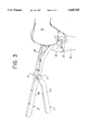
- FIG. 3 shows a typical embodiment of the present invention on a flexed knee before application of a distraction force
- FIG. 4 shows a typical embodiment of the present invention on a flexed knee after application of a distraction force
- FIG. 5 shows a typical embodiment of the present invention on a flexed knee after application of a distraction force, used in combination with a spacer block to position the posterior femoral cut at a predetermined distance from the cut tibial surface;
- FIG. 6 is a top plan view of a preferred embodiment of the invention having an anterior-posterior chamfer cutting guide mounted thereon;
- FIG. 7 is a side plan view of the preferred embodiment shown in FIG. 6;
- FIG. 8 is a sectional view along the line 8--8 of FIG. 7;
- FIG. 9 is an exploded perspective view of the spacer shim and platform used in the preferred embodiment.
- FIGS. 1 and 2 A typical embodiment of the knee flexion gap distraction device is illustrated in FIGS. 1 and 2.
- the femur 13 is shown at 13 and the tibia at 15.
- the present invention includes a tibial device 1 with a contoured handle 10 and a broad, T-shaped platform 12 on the opposite end.
- a femoral device 2 has a contoured handle 14 and a cylindrical opposite end 16.
- Tibial device 1 and femoral device 2 are pivotally joined by a bolt 3 and nut 4 to form a hinge.
- FIGS. 3, 4 and 5 show one use of the knee flexion-gap distraction device.
- the T-shaped platform 12 of tibial device 1 is placed in the center of the cut tibial surface 18, with the knee flexed to 90°.
- the cylindrical end 16 of femoral device 2 is inserted into a pre-drilled opening (not shown) which leads from the center of the femoral intercondylar notch into the femoral intramedullary canal.
- the contoured handles 10 and 14 of tibial device 1 and femoral device 2 together form a hand-grip which, when squeezed, applied a distraction force between the distal femur and proximal tibial surface.
- the T-shaped platform 12 of tibial device 1 maintains the distal femur centered above the tibia in a medial to lateral direction.
- the cylindrical end 16 of femoral device 2 lifts the distal femur away from the tibial surface 18 while allowing rotation of the femur 13 around an axis connecting the hip joint and the hole in the intercondylar area of the distal femur into which cylindrical end 16 of femoral device 2 is inserted.
- Rotation of the femur 13 around this axis allows approximate equalization of tension applied to the medial and lateral ligaments. Tactile feedback through the hand-held squeeze grip or direct palpation of the knee ligaments will help determine the appropriate amount of distraction force. During maintenance of the distraction force, the optimal anterior-posterior positioning of the femoral components may be measured directly from the cut surface of the tibia.
- a spacer block 5 may be placed on the cut tibial surface and used to determine the correct position of the posterior femoral cut.
- the spacer block 5 could be used as a tibial platform for the knee flexion gap distraction device, with the spacer block 5 and distraction device linked together.
- FIGS. 6-9 illustrate a preferred embodiment of the invention in which the platform which engages the tibia articulates or pivots with respect to the tibial lever.
- the tibial component is shown as a lever 21 and the femoral component as lever 22.
- the levers 21 and 22 are pivotally connected by a nut and bolt (or in any other suitable way) which form an axle 23.
- the levers 21 and 22 include handle portions 30 and 34 at one end which can be gripped by the surgeon to separate the opposite ends of the levers when the handles are squeezed.
- tibial lever 21 includes a platform 32 and the femoral lever 22 includes an elongated intramedullary rod 36.
- tibial platform 32 is connected to the distal end of tibial lever 21 by means of a pin 38 which permits the platform 32 to pivot with respect to the lever.
- shape of platform 32 is different from the shape of platform 12.
- Platform 32 includes a flat bottom surface 40 which is adapted to rest on the flat (cut) proximal surface of the tibia, a flat upper surface 42 which supports a cutting guide as described below, and a curved distal face 44 which enables the platform to fit beneath the femoral condyles.
- a conventional tension spring 46 and handle screw 48 are provided at the handle end of the instrument.
- the tension spring biases the handles 30 and 34 apart.
- the handle screw 48 enables the surgeon to lock the distraction device in position after the knee has been distracted.
- FIGS. 6-9 provides advantages as compared to the embodiment of FIGS. 1-5 in that the tibial platform 32 which rests on the cut tibial surface has a larger surface area in contact with the surface of the tibia; thus, it is less likely to indent the relatively soft tibial surface. Moreover, the tibial platform 32 is less likely to move relative to the tibial surface which means that the instrument itself is more stable. Also, and as explained further below, in the embodiment of FIGS. 6-9, the tibial platform itself (with spacer shims, if necessary) positions the cutting guide a predetermined distance from the tibial surface. This allows the surgeon to create a flexion gap of a precise size and shape. In the embodiment of FIGS. 1-5, a separate spacer block is placed on the tibia and used to position the cutting guide. The embodiment of FIGS. 6-9 reduces the number of instrument components used at one time, thereby simplifying the technique.
- FIGS. 6-9 also show a representative cutting guide used in conjunction with the invention.
- the cutting guide 60 is bifurcated (see FIG. 8) so that the intermedullary rod 36 can pass between its two sections.
- the cutting guide may rest on a flat spacer shim 62 which sits on the upper flat surface 42 of the tibial platform 32.
- the function of the spacer shim 62 is to position the cutting guide 60 relative to the femur (shown in dotted lines) so that the posterior femoral cut will be made at the proper location.
- Spacer shim 62 may include downwardly depending registration pins 64 which engage complementary holes 65 in the upper surface of platform 32 to retain the spacer shim in position.
- the cutting guide 60 includes slots 61A and 61P to guide a cutting tool to make the anterior femoral and posterior femoral cuts, respectively.
- slots (not numbered) are provided for the anterior chamfer and posterior chamfer cuts.
- the use of such cutting guides is conventional.
- the cutting guide also includes an outrigger stylus 66 which is adjustably attached to a vertical shaft 68 by a bolt 69 which passes through slot 71 in stylus 66.
- Shaft 68 is slidably received in a suitable bore (not numbered) within the cutting guide 60.
- the stylus point should ideally fall to the position of slot 61A (which defines the anterior femoral cut).
- the actual position of the slot 61A relative to the anterior femoral surface 73 can be determined by the surgeon through a viewing slot or window 70 in the "back" of the cutting guide 60 (see FIG. 8).
- the position of slot 61A relative to the anterior femoral surface can be indicated by the position of a mark 72 on shaft 68, which is visible within the window 70, and which represents the point of the stylus, i.e. a point flush with the anterior femoral surface 73. If mark 72 is positioned in the center of window 70, the guide is the proper size for the patient's femur, i.e. the anterior femoral cut will be flush with the femur.
- FIGS. 6-9 The instrument shown in FIGS. 6-9 is used as follows.
- the tibial cut and the distal femoral cut will have been made in conventional fashion. Osteophytes from the femur and tibia are removed. If a posterior cruciate ligament (PCL) sacrificing implant is to be used, the ligament is then transected. The knee is brought to extension and the extension gap balanced by soft tissue releases. The size and balance of the extension gap is checked with spacer blocks. The spacer block is then removed and the knee flexed to 90°.
- PCL posterior cruciate ligament
- the intramedullary rod 36 of femoral lever 22 is placed a short distance into the intermedullary canal of the patient's femur.
- the tibial platform 32 of the tibial component is then rested on the cut surface of the tibia, with its curved face 44 placed slightly beneath the posterior femoral condyles.
- the surgeon then squeezes the hand grip 30/34 to separate or distract the flexion gap.
- the handle nut 48 is then tightened to maintain the distracted position.
- the femur can rotate around the rod 36 so that the medial and lateral sections are equally distracted.
- a cutting guide 60 is placed over the distractor so that it rests against the cut distal surface of the femur and on the upper surface 42 of the tibial platform. Because of the thickness of the tibial platform, when the cutting guide rests on it, the posterior femoral cut will result in a flexion gap the same size as an 8 mm tibial component.
- the flexion gap can be adjusted in size for any other tibial component thickness by placing an appropriate spacer shim 62 between the guide 60 and platform 32.
- the outrigger stylus 66 is used for this purpose. If the indicator mark 72 within window 70 is centered, the cutting guide in position is properly sized, which means that the anterior femoral cut will be made at the proper position relative to the posterior cut for the patient's femur. If the mark is adjacent the numerals "2" or "4" the surgeon knows the size of the cutting guide required to properly place the anterior cut. The fact that the surgeon is provided with an indication of the size of the proper cutting guide is a useful feature of the invention.
- the tension in the flexion gap distractor can be adjusted within reasonable limits to ensure that the anterior cut will be flush with the anterior femur. Adjustment of the flexion gap distractor will affect ligament tension in the flexion gap which is a trade-off that the surgeon must handle.
- the cutting guide After the cutting guide has been selected and positioned so that the proper cuts will be provided, the cutting guide is nailed onto the femur (the nail holes are not shown in the drawings). The distractor is then removed and the cuts are made. If a PCL sacrificing implant is to be used, the notch is created with a notch guide.
- the tibial platform is not readily detachable from the tibial lever and spacer shims are used if necessary to properly position the cutting guide.
- a detachable connection between the tibial lever and tibial platform may be used so that the surgeon would be able to select a tibial platform with the proper dimensions.
- Different ways can be used to releasably connect the tibial lever and platform.
- the forward end of the tibial lever may include a transverse cylinder which can be received within a shallow complementary slot in the upper surface of the tibial platform.
- the forward end of the lever may be pivotally attached to a vertical post which is adapted to fit into a complementary hole in the upper surface of the platform.
- a simpler construction would he to shape the forward end of the tibial lever so that it fits into a complementary slot within the upper surface of the tibial platform.
- the invention thus provides an improved flexion gap distraction device which automatically matches the flexion and extension gaps. It externally rotates the femoral component of the knee because in most cases the medial collateral ligament will be tight and internally rotate the femur relative to the cutting guide. It provides a way to cut the anterior femur flush with the shaft and will work for both PCL retaining and PCL sacrificing knees. With minor modifications the invention should have utility for any brand of knee prosthesis.
- the present invention has significant advantages over the prior art.
- the use of femoral rotation to equalize tension among the ligaments eliminates the need for separate distractors for each condyle, thereby greatly simplifying instrument construction and use.
- ligament balancing is more reliable and reproducible, especially in cases of condylar erosion and pre-existing deformity.
- the method of engaging the distal femur may be modified to form a hook which engages the femoral intercondylar notch or modified to form a linkage between an intramedullary rod and the distraction device.
- the method of engaging the proximal tibia may take the form of a platform or intramedullary rod.
- the methods of applying, measuring, or maintaining the distraction force may include springs, ratchets, suspended weights, strings, elastic bands, screws, or gear mechanisms.
- the methods of positioning the posterior femoral cut relative to tibial reference points may include a separate measuring device, extensions of the tibial portion of the distraction device, or guides which are positioned relative to the tibia or the tibial portion of the distraction device. Accordingly, the scope of the invention should be determined not by the embodiments illustrated, but by the appended claims and their legal equivalents.
Abstract
Description
Claims (6)
Priority Applications (1)
| Application Number | Priority Date | Filing Date | Title |
|---|---|---|---|
| US08/500,732 US5649929A (en) | 1995-07-10 | 1995-07-10 | Knee joint flexion-gap distraction device |
Applications Claiming Priority (1)
| Application Number | Priority Date | Filing Date | Title |
|---|---|---|---|
| US08/500,732 US5649929A (en) | 1995-07-10 | 1995-07-10 | Knee joint flexion-gap distraction device |
Publications (1)
| Publication Number | Publication Date |
|---|---|
| US5649929A true US5649929A (en) | 1997-07-22 |
Family
ID=23990689
Family Applications (1)
| Application Number | Title | Priority Date | Filing Date |
|---|---|---|---|
| US08/500,732 Expired - Lifetime US5649929A (en) | 1995-07-10 | 1995-07-10 | Knee joint flexion-gap distraction device |
Country Status (1)
| Country | Link |
|---|---|
| US (1) | US5649929A (en) |
Cited By (70)
| Publication number | Priority date | Publication date | Assignee | Title |
|---|---|---|---|---|
| DE29910761U1 (en) * | 1999-06-19 | 2000-11-23 | Mathys Medizinaltechnik Ag Bet | Ligament tensioning device for non-spherical joints |
| US6575980B1 (en) * | 1997-01-28 | 2003-06-10 | New York Society For The Ruptured And Crippled Maintaining The Hospital For Special Surgery | Method and apparatus for femoral resection |
| US20030120273A1 (en) * | 2001-12-21 | 2003-06-26 | Cole J. Dean | Surgical distractor frame |
| US20030216741A1 (en) * | 2001-06-20 | 2003-11-20 | Sanford Adam H. | Method and apparatus for resecting a distal femur and a proximal tibia in preparation for implementing a partial knee prosthesis |
| US20030225415A1 (en) * | 2002-01-18 | 2003-12-04 | Alain Richard | Method and apparatus for reconstructing bone surfaces during surgery |
| US20030225416A1 (en) * | 2002-05-21 | 2003-12-04 | Bonvallet Todd C. | Instruments and techniques for separating bony structures |
| US6679888B2 (en) | 2001-05-29 | 2004-01-20 | Synthes | Femur lever |
| US20040236424A1 (en) * | 2001-05-25 | 2004-11-25 | Imaging Therapeutics, Inc. | Patient selectable joint arthroplasty devices and surgical tools facilitating increased accuracy, speed and simplicity in performing total and partial joint arthroplasty |
| US20050049603A1 (en) * | 2002-07-23 | 2005-03-03 | Ortho Development Corporation | Knee balancing block |
| US20050143744A1 (en) * | 2003-12-30 | 2005-06-30 | Keeven Richard D. | Augments for surgical instruments |
| US20050177170A1 (en) * | 2004-02-06 | 2005-08-11 | Synvasive Technology, Inc. | Dynamic knee balancer with pressure sensing |
| FR2867963A1 (en) * | 2004-03-26 | 2005-09-30 | Francis Guillaume | ANCILLARY SET TO IMPLEMENT A KNEE PROSTHESIS |
| US20060015120A1 (en) * | 2002-04-30 | 2006-01-19 | Alain Richard | Determining femoral cuts in knee surgery |
| US20060089653A1 (en) * | 2002-06-28 | 2006-04-27 | Auger Daniel D | Kit, guide and method for locating distal femoral resection plane |
| WO2007036694A1 (en) | 2005-09-30 | 2007-04-05 | Depuy International Limited | Instrument assembly for use in knee joint replacement surgery |
| WO2007036699A1 (en) | 2005-09-30 | 2007-04-05 | Depuy International Limited | A distractor instrument |
| US20080015606A1 (en) * | 2006-06-21 | 2008-01-17 | Howmedica Osteonics Corp. | Unicondylar knee implants and insertion methods therefor |
| US20080065084A1 (en) * | 2002-08-23 | 2008-03-13 | Orthosoft Inc. | Surgical universal positioning block and tool guide |
| GB2445620A (en) * | 2007-01-13 | 2008-07-16 | Derek James Wallace Mcminn | Instrumentation for knee surgery |
| US20080243127A1 (en) * | 2001-05-25 | 2008-10-02 | Conformis, Inc. | Surgical Tools for Arthroplasty |
| US20090078592A1 (en) * | 2005-01-28 | 2009-03-26 | Fresenius Medical Care North America | Systems and methods for delivery of peritoneal dialysis (pd) solutions |
| US7534263B2 (en) | 2001-05-25 | 2009-05-19 | Conformis, Inc. | Surgical tools facilitating increased accuracy, speed and simplicity in performing joint arthroplasty |
| US20090192511A1 (en) * | 2008-01-28 | 2009-07-30 | Haffenreffer Mark E | Surgical instruments and instrument handle having support brace |
| US20090326544A1 (en) * | 2008-06-27 | 2009-12-31 | Ryan Chessar | Knee ligament balancer |
| US20100160919A1 (en) * | 2006-06-30 | 2010-06-24 | Howmedica Osteonics Corp. | Femoral component and instrumentation |
| US20100212138A1 (en) * | 2009-02-24 | 2010-08-26 | Wright Medical Technology, Inc. | Method For Forming A Patient Specific Surgical Guide Mount |
| US20100222783A1 (en) * | 2009-03-02 | 2010-09-02 | Zimmer, Inc. | Anterior cortex referencing extramedullary femoral cut guide |
| US7799084B2 (en) | 2002-10-23 | 2010-09-21 | Mako Surgical Corp. | Modular femoral component for a total knee joint replacement for minimally invasive implantation |
| US20100249658A1 (en) * | 2009-03-31 | 2010-09-30 | Sherman Jason T | Device and method for determining force of a knee joint |
| US20100249660A1 (en) * | 2009-03-31 | 2010-09-30 | Sherman Jason T | System and method for displaying joint force data |
| US20100249789A1 (en) * | 2009-03-31 | 2010-09-30 | Mick Rock | Method for performing an orthopaedic surgical procedure |
| US20100303324A1 (en) * | 2001-05-25 | 2010-12-02 | Conformis, Inc. | Methods and Compositions for Articular Repair |
| US7881768B2 (en) | 1998-09-14 | 2011-02-01 | The Board Of Trustees Of The Leland Stanford Junior University | Assessing the condition of a joint and devising treatment |
| US8036729B2 (en) | 1998-09-14 | 2011-10-11 | The Board Of Trustees Of The Leland Stanford Junior University | Assessing the condition of a joint and devising treatment |
| US8066708B2 (en) | 2001-05-25 | 2011-11-29 | Conformis, Inc. | Patient selectable joint arthroplasty devices and surgical tools |
| GB2482702A (en) * | 2010-08-11 | 2012-02-15 | Biomet Uk Healthcare Ltd | Ligament balancer |
| US20120130376A1 (en) * | 2008-06-25 | 2012-05-24 | Small Bone Innovations, Inc. | Surgical instrumentation and methods of use for implanting a prosthesis |
| US8265730B2 (en) | 1998-09-14 | 2012-09-11 | The Board Of Trustees Of The Leland Stanford Junior University | Assessing the condition of a joint and preventing damage |
| US8377129B2 (en) | 2001-05-25 | 2013-02-19 | Conformis, Inc. | Joint arthroplasty devices and surgical tools |
| US8439926B2 (en) | 2001-05-25 | 2013-05-14 | Conformis, Inc. | Patient selectable joint arthroplasty devices and surgical tools |
| US8500740B2 (en) | 2006-02-06 | 2013-08-06 | Conformis, Inc. | Patient-specific joint arthroplasty devices for ligament repair |
| US8556830B2 (en) | 2009-03-31 | 2013-10-15 | Depuy | Device and method for displaying joint force data |
| US20130296860A1 (en) * | 2008-10-23 | 2013-11-07 | Synvasive Technology, Inc. | Knee balancing for revision procedures |
| US8582843B2 (en) * | 2008-08-12 | 2013-11-12 | Wyeth Pharmaceuticals, Inc. | Morphometry of the human knee joint and prediction for osteoarthritis |
| US8623026B2 (en) | 2006-02-06 | 2014-01-07 | Conformis, Inc. | Patient selectable joint arthroplasty devices and surgical tools incorporating anatomical relief |
| US8663234B2 (en) | 2011-08-01 | 2014-03-04 | Zimmer, Inc. | Combination ligament tensioner and alignment device |
| US8740817B2 (en) | 2009-03-31 | 2014-06-03 | Depuy (Ireland) | Device and method for determining forces of a patient's joint |
| US8758355B2 (en) | 2004-02-06 | 2014-06-24 | Synvasive Technology, Inc. | Dynamic knee balancer with pressure sensing |
| US20140228851A1 (en) * | 2013-02-08 | 2014-08-14 | Orthopaedic International, Inc. | Total knee arthroplasty methods, systems, and instruments |
| US8808303B2 (en) | 2009-02-24 | 2014-08-19 | Microport Orthopedics Holdings Inc. | Orthopedic surgical guide |
| US8951260B2 (en) | 2001-05-25 | 2015-02-10 | Conformis, Inc. | Surgical cutting guide |
| US9192459B2 (en) | 2000-01-14 | 2015-11-24 | Bonutti Skeletal Innovations Llc | Method of performing total knee arthroplasty |
| US9286686B2 (en) | 1998-09-14 | 2016-03-15 | The Board Of Trustees Of The Leland Stanford Junior University | Assessing the condition of a joint and assessing cartilage loss |
| US9381011B2 (en) | 2012-03-29 | 2016-07-05 | Depuy (Ireland) | Orthopedic surgical instrument for knee surgery |
| US9486226B2 (en) | 2012-04-18 | 2016-11-08 | Conformis, Inc. | Tibial guides, tools, and techniques for resecting the tibial plateau |
| US9545459B2 (en) | 2012-03-31 | 2017-01-17 | Depuy Ireland Unlimited Company | Container for surgical instruments and system including same |
| US20170128057A1 (en) * | 2005-02-08 | 2017-05-11 | G. Lynn Rasmussen | Arthoplasty systems and methods for optimally aligning and tensioning a knee prosthesis |
| US9649117B2 (en) | 2009-02-24 | 2017-05-16 | Microport Orthopedics Holdings, Inc. | Orthopedic surgical guide |
| US9675471B2 (en) | 2012-06-11 | 2017-06-13 | Conformis, Inc. | Devices, techniques and methods for assessing joint spacing, balancing soft tissues and obtaining desired kinematics for joint implant components |
| US9750619B2 (en) | 2011-09-07 | 2017-09-05 | Depuy Ireland Unlimited Company | Surgical instrument |
| US10070973B2 (en) | 2012-03-31 | 2018-09-11 | Depuy Ireland Unlimited Company | Orthopaedic sensor module and system for determining joint forces of a patient's knee joint |
| US10098761B2 (en) | 2012-03-31 | 2018-10-16 | DePuy Synthes Products, Inc. | System and method for validating an orthopaedic surgical plan |
| US10206792B2 (en) | 2012-03-31 | 2019-02-19 | Depuy Ireland Unlimited Company | Orthopaedic surgical system for determining joint forces of a patients knee joint |
| US10231744B2 (en) * | 2009-08-20 | 2019-03-19 | Howmedica Osteonics Corp. | Flexible ACL instrumentation, kit and method |
| AU2018282424B2 (en) * | 2006-02-08 | 2021-01-21 | G Lynn Rasmussen | Guide assembly for guiding cuts to a femur and tibia during a knee arthroplasty |
| US11000296B2 (en) | 2017-12-20 | 2021-05-11 | Encore Medical, L.P. | Joint instrumentation and associated methods of use |
| US11013607B2 (en) | 2017-09-22 | 2021-05-25 | Encore Medical, L.P. | Talar ankle implant |
| US11357644B2 (en) | 2011-10-24 | 2022-06-14 | Synvasive Technology, Inc. | Knee balancing devices, systems and methods |
| US11432811B2 (en) * | 2019-05-09 | 2022-09-06 | Mako Surgical Corp. | Joint gap balancing lever and methods of use thereof |
| US11678894B2 (en) | 2017-12-15 | 2023-06-20 | Jonathan P. Cabot | Knee balancing instrument |
Citations (28)
| Publication number | Priority date | Publication date | Assignee | Title |
|---|---|---|---|---|
| US3750652A (en) * | 1971-03-05 | 1973-08-07 | J Sherwin | Knee retractor |
| US3840014A (en) * | 1971-09-24 | 1974-10-08 | Nat Res Dev | Retractor for hip joint surgery |
| US3916907A (en) * | 1974-06-21 | 1975-11-04 | Wendell C Peterson | Spreader instrument for use in performing a spinal fusion |
| US4066082A (en) * | 1975-04-24 | 1978-01-03 | Ramot University Authority For Applied Research And Industrial Development Ltd. | Force applicator including indicator |
| US4220146A (en) * | 1979-01-18 | 1980-09-02 | Cloutier Jean Marie | Biplanar joint distractor |
| US4474177A (en) * | 1983-03-09 | 1984-10-02 | Wright Manufacturing Company | Method and apparatus for shaping a distal femoral surface |
| US4501266A (en) * | 1983-03-04 | 1985-02-26 | Biomet, Inc. | Knee distraction device |
| US4524766A (en) * | 1982-01-07 | 1985-06-25 | Petersen Thomas D | Surgical knee alignment method and system |
| US4566448A (en) * | 1983-03-07 | 1986-01-28 | Rohr Jr William L | Ligament tensor and distal femoral resector guide |
| US4566488A (en) * | 1980-10-28 | 1986-01-28 | Grove Valve And Regulator Company | Multi-stage pressure reducing system |
| US4567886A (en) * | 1983-01-06 | 1986-02-04 | Petersen Thomas D | Flexion spacer guide for fitting a knee prosthesis |
| US4567885A (en) * | 1981-11-03 | 1986-02-04 | Androphy Gary W | Triplanar knee resection system |
| US4646729A (en) * | 1982-02-18 | 1987-03-03 | Howmedica, Inc. | Prosthetic knee implantation |
| US4722330A (en) * | 1986-04-22 | 1988-02-02 | Dow Corning Wright Corporation | Femoral surface shaping guide for knee implants |
| US4787383A (en) * | 1985-12-19 | 1988-11-29 | Howmedica, Inc. | Prosthetic knee implantation |
| US4825857A (en) * | 1982-02-18 | 1989-05-02 | Howmedica, Inc. | Prosthetic knee implantation |
| US4898161A (en) * | 1986-12-05 | 1990-02-06 | S+G Implants Gmbh | Forceps for pushing apart vertebrae |
| US4935023A (en) * | 1989-01-09 | 1990-06-19 | Dow Corning Wright | Femoral surface shaping guide for knee implants |
| US4938762A (en) * | 1987-12-16 | 1990-07-03 | Protek Ag | Reference system for implantation of condylar total knee prostheses |
| US5002547A (en) * | 1987-02-07 | 1991-03-26 | Pfizer Hospital Products Group, Inc. | Apparatus for knee prosthesis |
| US5053037A (en) * | 1991-03-07 | 1991-10-01 | Smith & Nephew Richards Inc. | Femoral instrumentation for long stem surgery |
| US5116338A (en) * | 1988-02-03 | 1992-05-26 | Pfizer Hospital Products Group, Inc. | Apparatus for knee prosthesis |
| US5213112A (en) * | 1992-01-29 | 1993-05-25 | Pfizer Hospital Products Group, Inc. | Tension meter for orthopedic surgery |
| US5234433A (en) * | 1989-09-26 | 1993-08-10 | Kirschner Medical Corporation | Method and instrumentation for unicompartmental total knee arthroplasty |
| US5263498A (en) * | 1990-01-08 | 1993-11-23 | Caspari Richard B | Method of arthroscopically preparing an articular bone surface |
| US5431653A (en) * | 1993-07-06 | 1995-07-11 | Callaway; George H. | Knee joint flexion-gap distraction device |
| US5464406A (en) * | 1992-12-09 | 1995-11-07 | Ritter; Merrill A. | Instrumentation for revision surgery |
| US5540696A (en) * | 1995-01-06 | 1996-07-30 | Zimmer, Inc. | Instrumentation for use in orthopaedic surgery |
-
1995
- 1995-07-10 US US08/500,732 patent/US5649929A/en not_active Expired - Lifetime
Patent Citations (28)
| Publication number | Priority date | Publication date | Assignee | Title |
|---|---|---|---|---|
| US3750652A (en) * | 1971-03-05 | 1973-08-07 | J Sherwin | Knee retractor |
| US3840014A (en) * | 1971-09-24 | 1974-10-08 | Nat Res Dev | Retractor for hip joint surgery |
| US3916907A (en) * | 1974-06-21 | 1975-11-04 | Wendell C Peterson | Spreader instrument for use in performing a spinal fusion |
| US4066082A (en) * | 1975-04-24 | 1978-01-03 | Ramot University Authority For Applied Research And Industrial Development Ltd. | Force applicator including indicator |
| US4220146A (en) * | 1979-01-18 | 1980-09-02 | Cloutier Jean Marie | Biplanar joint distractor |
| US4566488A (en) * | 1980-10-28 | 1986-01-28 | Grove Valve And Regulator Company | Multi-stage pressure reducing system |
| US4567885A (en) * | 1981-11-03 | 1986-02-04 | Androphy Gary W | Triplanar knee resection system |
| US4524766A (en) * | 1982-01-07 | 1985-06-25 | Petersen Thomas D | Surgical knee alignment method and system |
| US4646729A (en) * | 1982-02-18 | 1987-03-03 | Howmedica, Inc. | Prosthetic knee implantation |
| US4825857A (en) * | 1982-02-18 | 1989-05-02 | Howmedica, Inc. | Prosthetic knee implantation |
| US4567886A (en) * | 1983-01-06 | 1986-02-04 | Petersen Thomas D | Flexion spacer guide for fitting a knee prosthesis |
| US4501266A (en) * | 1983-03-04 | 1985-02-26 | Biomet, Inc. | Knee distraction device |
| US4566448A (en) * | 1983-03-07 | 1986-01-28 | Rohr Jr William L | Ligament tensor and distal femoral resector guide |
| US4474177A (en) * | 1983-03-09 | 1984-10-02 | Wright Manufacturing Company | Method and apparatus for shaping a distal femoral surface |
| US4787383A (en) * | 1985-12-19 | 1988-11-29 | Howmedica, Inc. | Prosthetic knee implantation |
| US4722330A (en) * | 1986-04-22 | 1988-02-02 | Dow Corning Wright Corporation | Femoral surface shaping guide for knee implants |
| US4898161A (en) * | 1986-12-05 | 1990-02-06 | S+G Implants Gmbh | Forceps for pushing apart vertebrae |
| US5002547A (en) * | 1987-02-07 | 1991-03-26 | Pfizer Hospital Products Group, Inc. | Apparatus for knee prosthesis |
| US4938762A (en) * | 1987-12-16 | 1990-07-03 | Protek Ag | Reference system for implantation of condylar total knee prostheses |
| US5116338A (en) * | 1988-02-03 | 1992-05-26 | Pfizer Hospital Products Group, Inc. | Apparatus for knee prosthesis |
| US4935023A (en) * | 1989-01-09 | 1990-06-19 | Dow Corning Wright | Femoral surface shaping guide for knee implants |
| US5234433A (en) * | 1989-09-26 | 1993-08-10 | Kirschner Medical Corporation | Method and instrumentation for unicompartmental total knee arthroplasty |
| US5263498A (en) * | 1990-01-08 | 1993-11-23 | Caspari Richard B | Method of arthroscopically preparing an articular bone surface |
| US5053037A (en) * | 1991-03-07 | 1991-10-01 | Smith & Nephew Richards Inc. | Femoral instrumentation for long stem surgery |
| US5213112A (en) * | 1992-01-29 | 1993-05-25 | Pfizer Hospital Products Group, Inc. | Tension meter for orthopedic surgery |
| US5464406A (en) * | 1992-12-09 | 1995-11-07 | Ritter; Merrill A. | Instrumentation for revision surgery |
| US5431653A (en) * | 1993-07-06 | 1995-07-11 | Callaway; George H. | Knee joint flexion-gap distraction device |
| US5540696A (en) * | 1995-01-06 | 1996-07-30 | Zimmer, Inc. | Instrumentation for use in orthopaedic surgery |
Cited By (209)
| Publication number | Priority date | Publication date | Assignee | Title |
|---|---|---|---|---|
| US6575980B1 (en) * | 1997-01-28 | 2003-06-10 | New York Society For The Ruptured And Crippled Maintaining The Hospital For Special Surgery | Method and apparatus for femoral resection |
| US7881768B2 (en) | 1998-09-14 | 2011-02-01 | The Board Of Trustees Of The Leland Stanford Junior University | Assessing the condition of a joint and devising treatment |
| US8862202B2 (en) | 1998-09-14 | 2014-10-14 | The Board Of Trustees Of The Leland Stanford Junior University | Assessing the condition of a joint and preventing damage |
| US9286686B2 (en) | 1998-09-14 | 2016-03-15 | The Board Of Trustees Of The Leland Stanford Junior University | Assessing the condition of a joint and assessing cartilage loss |
| US8369926B2 (en) | 1998-09-14 | 2013-02-05 | The Board Of Trustees Of The Leland Stanford Junior University | Assessing the condition of a joint and devising treatment |
| US8306601B2 (en) | 1998-09-14 | 2012-11-06 | The Board Of Trustees Of The Leland Stanford Junior University | Assessing the condition of a joint and devising treatment |
| US8265730B2 (en) | 1998-09-14 | 2012-09-11 | The Board Of Trustees Of The Leland Stanford Junior University | Assessing the condition of a joint and preventing damage |
| USRE43282E1 (en) | 1998-09-14 | 2012-03-27 | The Board Of Trustees Of The Leland Stanford Junior University | Assessing the condition of a joint and devising treatment |
| US8112142B2 (en) | 1998-09-14 | 2012-02-07 | The Board Of Trustees Of The Leland Stanford Junior University | Assessing the condition of a joint and devising treatment |
| US8036729B2 (en) | 1998-09-14 | 2011-10-11 | The Board Of Trustees Of The Leland Stanford Junior University | Assessing the condition of a joint and devising treatment |
| DE29910761U1 (en) * | 1999-06-19 | 2000-11-23 | Mathys Medizinaltechnik Ag Bet | Ligament tensioning device for non-spherical joints |
| US9192459B2 (en) | 2000-01-14 | 2015-11-24 | Bonutti Skeletal Innovations Llc | Method of performing total knee arthroplasty |
| US8585708B2 (en) | 2001-05-25 | 2013-11-19 | Conformis, Inc. | Patient selectable joint arthroplasty devices and surgical tools |
| US8617172B2 (en) | 2001-05-25 | 2013-12-31 | Conformis, Inc. | Joint arthroplasty devices and surgical tools |
| US8529630B2 (en) | 2001-05-25 | 2013-09-10 | Conformis, Inc. | Patient selectable joint arthroplasty devices and surgical tools |
| US9125673B2 (en) | 2001-05-25 | 2015-09-08 | Conformis, Inc. | Joint arthroplasty devices and surgical tools |
| US9125672B2 (en) | 2001-05-25 | 2015-09-08 | Conformis, Inc. | Joint arthroplasty devices and surgical tools |
| US8551099B2 (en) | 2001-05-25 | 2013-10-08 | Conformis, Inc. | Surgical tools for arthroplasty |
| US8460304B2 (en) | 2001-05-25 | 2013-06-11 | Conformis, Inc. | Joint arthroplasty devices and surgical tools |
| US9216025B2 (en) | 2001-05-25 | 2015-12-22 | Conformis, Inc. | Joint arthroplasty devices and surgical tools |
| US9107679B2 (en) | 2001-05-25 | 2015-08-18 | Conformis, Inc. | Patient selectable joint arthroplasty devices and surgical tools |
| US9107680B2 (en) | 2001-05-25 | 2015-08-18 | Conformis, Inc. | Patient selectable joint arthroplasty devices and surgical tools |
| US8439926B2 (en) | 2001-05-25 | 2013-05-14 | Conformis, Inc. | Patient selectable joint arthroplasty devices and surgical tools |
| US8551169B2 (en) | 2001-05-25 | 2013-10-08 | Conformis, Inc. | Joint arthroplasty devices and surgical tools |
| US8377129B2 (en) | 2001-05-25 | 2013-02-19 | Conformis, Inc. | Joint arthroplasty devices and surgical tools |
| US9084617B2 (en) | 2001-05-25 | 2015-07-21 | Conformis, Inc. | Patient selectable joint arthroplasty devices and surgical tools |
| US9072531B2 (en) | 2001-05-25 | 2015-07-07 | Conformis, Inc. | Patient selectable joint arthroplasty devices and surgical tools |
| US9066728B2 (en) | 2001-05-25 | 2015-06-30 | Conformis, Inc. | Surgical tools facilitating increased accuracy, speed and simplicity in performing joint arthroplasty |
| US8551102B2 (en) | 2001-05-25 | 2013-10-08 | Conformis, Inc. | Joint arthroplasty devices and surgical tools |
| US8366771B2 (en) | 2001-05-25 | 2013-02-05 | Conformis, Inc. | Surgical tools facilitating increased accuracy, speed and simplicity in performing joint arthroplasty |
| US9055953B2 (en) | 2001-05-25 | 2015-06-16 | Conformis, Inc. | Methods and compositions for articular repair |
| US9023050B2 (en) | 2001-05-25 | 2015-05-05 | Conformis, Inc. | Surgical tools for arthroplasty |
| US20080243127A1 (en) * | 2001-05-25 | 2008-10-02 | Conformis, Inc. | Surgical Tools for Arthroplasty |
| US8998915B2 (en) | 2001-05-25 | 2015-04-07 | Conformis, Inc. | Joint arthroplasty devices and surgical tools |
| US8951260B2 (en) | 2001-05-25 | 2015-02-10 | Conformis, Inc. | Surgical cutting guide |
| US7534263B2 (en) | 2001-05-25 | 2009-05-19 | Conformis, Inc. | Surgical tools facilitating increased accuracy, speed and simplicity in performing joint arthroplasty |
| US8951259B2 (en) | 2001-05-25 | 2015-02-10 | Conformis, Inc. | Patient selectable joint arthroplasty devices and surgical tools |
| US8343218B2 (en) | 2001-05-25 | 2013-01-01 | Conformis, Inc. | Methods and compositions for articular repair |
| US8556907B2 (en) | 2001-05-25 | 2013-10-15 | Conformis, Inc. | Joint arthroplasty devices and surgical tools |
| US7618451B2 (en) | 2001-05-25 | 2009-11-17 | Conformis, Inc. | Patient selectable joint arthroplasty devices and surgical tools facilitating increased accuracy, speed and simplicity in performing total and partial joint arthroplasty |
| US9295482B2 (en) | 2001-05-25 | 2016-03-29 | Conformis, Inc. | Patient selectable joint arthroplasty devices and surgical tools |
| US8551103B2 (en) | 2001-05-25 | 2013-10-08 | Conformis, Inc. | Joint arthroplasty devices and surgical tools |
| US8768028B2 (en) | 2001-05-25 | 2014-07-01 | Conformis, Inc. | Methods and compositions for articular repair |
| US9358018B2 (en) | 2001-05-25 | 2016-06-07 | Conformis, Inc. | Joint arthroplasty devices and surgical tools |
| US8337501B2 (en) | 2001-05-25 | 2012-12-25 | Conformis, Inc. | Patient selectable joint arthroplasty devices and surgical tools |
| US8657827B2 (en) | 2001-05-25 | 2014-02-25 | Conformis, Inc. | Surgical tools for arthroplasty |
| US8556906B2 (en) | 2001-05-25 | 2013-10-15 | Conformis, Inc. | Joint arthroplasty devices and surgical tools |
| US8122582B2 (en) | 2001-05-25 | 2012-02-28 | Conformis, Inc. | Surgical tools facilitating increased accuracy, speed and simplicity in performing joint arthroplasty |
| US8641716B2 (en) | 2001-05-25 | 2014-02-04 | Conformis, Inc. | Joint arthroplasty devices and surgical tools |
| US8562618B2 (en) | 2001-05-25 | 2013-10-22 | Conformis, Inc. | Joint arthroplasty devices and surgical tools |
| US9186161B2 (en) | 2001-05-25 | 2015-11-17 | Conformis, Inc. | Surgical tools for arthroplasty |
| US20040236424A1 (en) * | 2001-05-25 | 2004-11-25 | Imaging Therapeutics, Inc. | Patient selectable joint arthroplasty devices and surgical tools facilitating increased accuracy, speed and simplicity in performing total and partial joint arthroplasty |
| US8105330B2 (en) | 2001-05-25 | 2012-01-31 | Conformis, Inc. | Patient selectable joint arthroplasty devices and surgical tools |
| US9579110B2 (en) | 2001-05-25 | 2017-02-28 | Conformis, Inc. | Patient selectable joint arthroplasty devices and surgical tools |
| US8568480B2 (en) | 2001-05-25 | 2013-10-29 | Conformis, Inc. | Joint arthroplasty devices and surgical tools |
| US8568479B2 (en) | 2001-05-25 | 2013-10-29 | Conformis, Inc. | Joint arthroplasty devices and surgical tools |
| US20100303324A1 (en) * | 2001-05-25 | 2010-12-02 | Conformis, Inc. | Methods and Compositions for Articular Repair |
| US8562611B2 (en) | 2001-05-25 | 2013-10-22 | Conformis, Inc. | Joint arthroplasty devices and surgical tools |
| US8083745B2 (en) | 2001-05-25 | 2011-12-27 | Conformis, Inc. | Surgical tools for arthroplasty |
| US7981158B2 (en) | 2001-05-25 | 2011-07-19 | Conformis, Inc. | Patient selectable joint arthroplasty devices and surgical tools |
| US8066708B2 (en) | 2001-05-25 | 2011-11-29 | Conformis, Inc. | Patient selectable joint arthroplasty devices and surgical tools |
| US8062302B2 (en) * | 2001-05-25 | 2011-11-22 | Conformis, Inc. | Surgical tools for arthroplasty |
| US8561278B2 (en) | 2001-05-25 | 2013-10-22 | Conformis, Inc. | Joint arthroplasty devices and surgical tools |
| US6679888B2 (en) | 2001-05-29 | 2004-01-20 | Synthes | Femur lever |
| US20030216741A1 (en) * | 2001-06-20 | 2003-11-20 | Sanford Adam H. | Method and apparatus for resecting a distal femur and a proximal tibia in preparation for implementing a partial knee prosthesis |
| US7285122B2 (en) * | 2001-06-20 | 2007-10-23 | Zimmer, Inc. | Method and apparatus for resecting a distal femur and a proximal tibia in preparation for implementing a partial knee prosthesis |
| US20030120273A1 (en) * | 2001-12-21 | 2003-06-26 | Cole J. Dean | Surgical distractor frame |
| US7311711B2 (en) | 2001-12-21 | 2007-12-25 | Cole J Dean | Surgical distractor frame |
| US20100172557A1 (en) * | 2002-01-16 | 2010-07-08 | Alain Richard | Method and apparatus for reconstructing bone surfaces during surgery |
| US7715602B2 (en) | 2002-01-18 | 2010-05-11 | Orthosoft Inc. | Method and apparatus for reconstructing bone surfaces during surgery |
| US20030225415A1 (en) * | 2002-01-18 | 2003-12-04 | Alain Richard | Method and apparatus for reconstructing bone surfaces during surgery |
| US8257360B2 (en) * | 2002-04-30 | 2012-09-04 | Orthosoft Inc. | Determining femoral cuts in knee surgery |
| US20060015120A1 (en) * | 2002-04-30 | 2006-01-19 | Alain Richard | Determining femoral cuts in knee surgery |
| US8523874B2 (en) | 2002-05-21 | 2013-09-03 | Warsaw Orthopedic, Inc. | Instruments and techniques for separating bony structures |
| US7749231B2 (en) | 2002-05-21 | 2010-07-06 | Warsaw Orthopedic, Inc. | Instruments and techniques for separating bony structures |
| US20030225416A1 (en) * | 2002-05-21 | 2003-12-04 | Bonvallet Todd C. | Instruments and techniques for separating bony structures |
| US20060089653A1 (en) * | 2002-06-28 | 2006-04-27 | Auger Daniel D | Kit, guide and method for locating distal femoral resection plane |
| US7329260B2 (en) | 2002-06-28 | 2008-02-12 | Depuy Products, Inc. | Kit, guide and method for locating distal femoral resection plane |
| US20050049603A1 (en) * | 2002-07-23 | 2005-03-03 | Ortho Development Corporation | Knee balancing block |
| US7628793B2 (en) | 2002-07-23 | 2009-12-08 | Ortho Development Corporation | Knee balancing block |
| US20080065084A1 (en) * | 2002-08-23 | 2008-03-13 | Orthosoft Inc. | Surgical universal positioning block and tool guide |
| US7896882B2 (en) * | 2002-08-23 | 2011-03-01 | Orthosoft Inc. | Surgical universal positioning block and tool guide |
| US7799084B2 (en) | 2002-10-23 | 2010-09-21 | Mako Surgical Corp. | Modular femoral component for a total knee joint replacement for minimally invasive implantation |
| EP1550416A1 (en) * | 2003-12-30 | 2005-07-06 | DePuy Products, Inc. | Instrument augments for filling a bone joint gap |
| JP2005193048A (en) * | 2003-12-30 | 2005-07-21 | Depuy Products Inc | Auxiliary tool of surgical instrument |
| US20050143744A1 (en) * | 2003-12-30 | 2005-06-30 | Keeven Richard D. | Augments for surgical instruments |
| US8025663B2 (en) | 2003-12-30 | 2011-09-27 | Depuy Products, Inc. | Augments for surgical instruments |
| US9572588B2 (en) | 2004-02-06 | 2017-02-21 | Synvasive Technology, Inc. | Dynamic knee balancer with force or pressure sensing |
| US20050177170A1 (en) * | 2004-02-06 | 2005-08-11 | Synvasive Technology, Inc. | Dynamic knee balancer with pressure sensing |
| US8491589B2 (en) | 2004-02-06 | 2013-07-23 | Synvasive Technology, Inc. | Dynamic knee balancer with pressure sensing |
| US20050177169A1 (en) * | 2004-02-06 | 2005-08-11 | Synvasive Technology, Inc. | Dynamic knee balancer |
| US7578821B2 (en) | 2004-02-06 | 2009-08-25 | Synvasive Technology, Inc. | Dynamic knee balancer with pressure sensing |
| US20050267485A1 (en) * | 2004-02-06 | 2005-12-01 | Synvasive Technology, Inc. | Dynamic knee balancer with opposing adjustment mechanism |
| US10555822B2 (en) | 2004-02-06 | 2020-02-11 | Synvasive Technology, Inc. | Dynamic knee balancer with force or pressure sensing |
| US8715290B2 (en) | 2004-02-06 | 2014-05-06 | Synvasive Technology, Inc. | Dynamic knee balancer with pressure sensing |
| US7837691B2 (en) | 2004-02-06 | 2010-11-23 | Synvasive Technology, Inc. | Dynamic knee balancer with opposing adjustment mechanism |
| US20090287310A1 (en) * | 2004-02-06 | 2009-11-19 | Synvasive Technology, Inc. | Dynamic knee balancer with pressure sensing |
| US7442196B2 (en) | 2004-02-06 | 2008-10-28 | Synvasive Technology, Inc. | Dynamic knee balancer |
| US8758355B2 (en) | 2004-02-06 | 2014-06-24 | Synvasive Technology, Inc. | Dynamic knee balancer with pressure sensing |
| US20070239157A1 (en) * | 2004-03-26 | 2007-10-11 | Francis Guillaume | Ancillary Assembly for Implanting a Knee Prosthesis |
| WO2005092205A1 (en) * | 2004-03-26 | 2005-10-06 | Francis Guillaume | Ancillary assembly for implanting a knee prosthesis |
| FR2867963A1 (en) * | 2004-03-26 | 2005-09-30 | Francis Guillaume | ANCILLARY SET TO IMPLEMENT A KNEE PROSTHESIS |
| US20090078592A1 (en) * | 2005-01-28 | 2009-03-26 | Fresenius Medical Care North America | Systems and methods for delivery of peritoneal dialysis (pd) solutions |
| US10517583B2 (en) * | 2005-02-08 | 2019-12-31 | G. Lynn Rasmussen | Arthoplasty systems and methods for optimally aligning and tensioning a knee prosthesis |
| US20170128057A1 (en) * | 2005-02-08 | 2017-05-11 | G. Lynn Rasmussen | Arthoplasty systems and methods for optimally aligning and tensioning a knee prosthesis |
| US11369359B2 (en) | 2005-02-08 | 2022-06-28 | Rasmussen Instruments, Llc | Arthroplasty systems and methods for optimally aligning and tensioning a knee prosthesis |
| WO2007036694A1 (en) | 2005-09-30 | 2007-04-05 | Depuy International Limited | Instrument assembly for use in knee joint replacement surgery |
| US20090270869A1 (en) * | 2005-09-30 | 2009-10-29 | Callum Colquhoun | Distractor instrument |
| US8998917B2 (en) | 2005-09-30 | 2015-04-07 | Depuy International Ltd. | Instrument assembly for use in knee joint replacement surgery |
| WO2007036699A1 (en) | 2005-09-30 | 2007-04-05 | Depuy International Limited | A distractor instrument |
| US9498199B2 (en) | 2005-09-30 | 2016-11-22 | Depuy International Ltd. | Distractor instrument |
| US9220517B2 (en) | 2006-02-06 | 2015-12-29 | Conformis, Inc. | Patient selectable joint arthroplasty devices and surgical tools |
| US9308053B2 (en) | 2006-02-06 | 2016-04-12 | Conformis, Inc. | Patient-specific joint arthroplasty devices for ligament repair |
| US9220516B2 (en) | 2006-02-06 | 2015-12-29 | Conformis, Inc. | Patient selectable joint arthroplasty devices and surgical tools |
| US8623026B2 (en) | 2006-02-06 | 2014-01-07 | Conformis, Inc. | Patient selectable joint arthroplasty devices and surgical tools incorporating anatomical relief |
| US8500740B2 (en) | 2006-02-06 | 2013-08-06 | Conformis, Inc. | Patient-specific joint arthroplasty devices for ligament repair |
| US9326780B2 (en) | 2006-02-06 | 2016-05-03 | Conformis, Inc. | Patient selectable joint arthroplasty devices and surgical tools incorporating anatomical relief |
| AU2018282424B2 (en) * | 2006-02-08 | 2021-01-21 | G Lynn Rasmussen | Guide assembly for guiding cuts to a femur and tibia during a knee arthroplasty |
| US20080015606A1 (en) * | 2006-06-21 | 2008-01-17 | Howmedica Osteonics Corp. | Unicondylar knee implants and insertion methods therefor |
| US20080015600A1 (en) * | 2006-06-21 | 2008-01-17 | Howmedica Osteonics Corp. | Unicondylar knee implants and insertion methods therefor |
| US8377069B2 (en) | 2006-06-21 | 2013-02-19 | Howmedica Osteonics Corp. | Unicondylar knee cutting guide |
| US8579905B2 (en) | 2006-06-21 | 2013-11-12 | Howmedica Osteonics Corp. | Unicondylar knee implants and insertion methods therefor |
| US20080015607A1 (en) * | 2006-06-21 | 2008-01-17 | Howmedica Osteonics Corp. | Unicondylar knee implants and insertion methods therefor |
| US7678115B2 (en) | 2006-06-21 | 2010-03-16 | Howmedia Osteonics Corp. | Unicondylar knee implants and insertion methods therefor |
| US20080015599A1 (en) * | 2006-06-21 | 2008-01-17 | Howmedica Osteonics Corp. | Unicondylar knee implants and insertion methods therefor |
| US8690881B2 (en) | 2006-06-30 | 2014-04-08 | Howmedica Osteonics Corp. | Femoral component and instrumentation |
| US20100160919A1 (en) * | 2006-06-30 | 2010-06-24 | Howmedica Osteonics Corp. | Femoral component and instrumentation |
| GB2445620B (en) * | 2007-01-13 | 2011-10-26 | Derek James Wallace Mcminn | Instrumentation for knee surgery |
| US20080177261A1 (en) * | 2007-01-13 | 2008-07-24 | Mcminn Derek James Wallace | Instrumentation for knee surgery |
| GB2445620A (en) * | 2007-01-13 | 2008-07-16 | Derek James Wallace Mcminn | Instrumentation for knee surgery |
| US20090192511A1 (en) * | 2008-01-28 | 2009-07-30 | Haffenreffer Mark E | Surgical instruments and instrument handle having support brace |
| US10517607B2 (en) * | 2008-06-25 | 2019-12-31 | Stryker European Holdings I, Llc | Surgical instrumentation and methods of use for implanting a prosthesis |
| US20120130376A1 (en) * | 2008-06-25 | 2012-05-24 | Small Bone Innovations, Inc. | Surgical instrumentation and methods of use for implanting a prosthesis |
| US20210298766A1 (en) * | 2008-06-25 | 2021-09-30 | Encore Medical, Lp Dba Djo Surgical | Surgical instrumentation and methods of use for implanting a prosthesis |
| US10987110B2 (en) | 2008-06-25 | 2021-04-27 | Encore Medical, Lp | Surgical instrumentation and methods of use for implanting a prosthesis |
| US10299800B2 (en) | 2008-06-25 | 2019-05-28 | Stryker European Holdings I, Llc | Surgical instrumentation and methods of use for implanting a prosthesis |
| US9993254B2 (en) | 2008-06-25 | 2018-06-12 | Stryker European Holdings I, Llc | Surgical instrumentation and methods of use for implanting a prosthesis |
| US8562617B2 (en) | 2008-06-27 | 2013-10-22 | DePuy Synthes Products, LLC | Knee ligament balancer |
| US20090326544A1 (en) * | 2008-06-27 | 2009-12-31 | Ryan Chessar | Knee ligament balancer |
| US8197489B2 (en) | 2008-06-27 | 2012-06-12 | Depuy Products, Inc. | Knee ligament balancer |
| US8582843B2 (en) * | 2008-08-12 | 2013-11-12 | Wyeth Pharmaceuticals, Inc. | Morphometry of the human knee joint and prediction for osteoarthritis |
| US20130296860A1 (en) * | 2008-10-23 | 2013-11-07 | Synvasive Technology, Inc. | Knee balancing for revision procedures |
| US9622761B2 (en) | 2008-10-23 | 2017-04-18 | Synvasive Technology, Inc. | Knee balancing for revision procedures |
| US9901353B2 (en) | 2009-02-24 | 2018-02-27 | Microport Holdings Inc. | Patient specific surgical guide locator and mount |
| US10512476B2 (en) | 2009-02-24 | 2019-12-24 | Microport Orthopedics Holdings, Inc. | Orthopedic surgical guide |
| US9883870B2 (en) | 2009-02-24 | 2018-02-06 | Microport Orthopedics Holdings Inc. | Method for forming a patient specific surgical guide mount |
| US8808303B2 (en) | 2009-02-24 | 2014-08-19 | Microport Orthopedics Holdings Inc. | Orthopedic surgical guide |
| US20100217338A1 (en) * | 2009-02-24 | 2010-08-26 | Wright Medical Technology, Inc. | Patient Specific Surgical Guide Locator and Mount |
| US11154305B2 (en) | 2009-02-24 | 2021-10-26 | Microport Orthopedics Holdings Inc. | Patient specific surgical guide locator and mount |
| US20100212138A1 (en) * | 2009-02-24 | 2010-08-26 | Wright Medical Technology, Inc. | Method For Forming A Patient Specific Surgical Guide Mount |
| US10973536B2 (en) | 2009-02-24 | 2021-04-13 | Microport Orthopedics Holdings, Inc. | Orthopedic surgical guide |
| US11779356B2 (en) | 2009-02-24 | 2023-10-10 | Microport Orthopedics Holdings, Inc. | Orthopedic surgical guide |
| US10660654B2 (en) | 2009-02-24 | 2020-05-26 | Microport Orthopedics Holdings Inc. | Method for forming a patient specific surgical guide mount |
| US10646238B2 (en) | 2009-02-24 | 2020-05-12 | Microport Orthopedics Holdings, Inc. | Systems and methods for installing an orthopedic implant |
| US11779347B2 (en) | 2009-02-24 | 2023-10-10 | Microport Orthopedics Holdings Inc. | System for forming a patient specific surgical guide mount |
| US9566075B2 (en) | 2009-02-24 | 2017-02-14 | Microport Orthopedics Holdings Inc. | Patient specific surgical guide locator and mount |
| US9017334B2 (en) | 2009-02-24 | 2015-04-28 | Microport Orthopedics Holdings Inc. | Patient specific surgical guide locator and mount |
| US9089342B2 (en) | 2009-02-24 | 2015-07-28 | Microport Orthopedics Holdings Inc. | Patient specific surgical guide locator and mount |
| US9949747B2 (en) | 2009-02-24 | 2018-04-24 | Microport Orthopedics Holdings, Inc. | Systems and methods for installing an orthopedic implant |
| US9642632B2 (en) | 2009-02-24 | 2017-05-09 | Microport Orthopedics Holdings Inc. | Orthopedic surgical guide |
| US11389177B2 (en) | 2009-02-24 | 2022-07-19 | Microport Orthopedics Holdings Inc. | Method for forming a patient specific surgical guide mount |
| US11464527B2 (en) | 2009-02-24 | 2022-10-11 | Microport Orthopedics Holdings Inc. | Systems and methods for installing an orthopedic implant |
| US9649117B2 (en) | 2009-02-24 | 2017-05-16 | Microport Orthopedics Holdings, Inc. | Orthopedic surgical guide |
| US10039557B2 (en) | 2009-02-24 | 2018-08-07 | Micorport Orthopedics Holdings, Inc. | Orthopedic surgical guide |
| US9675365B2 (en) | 2009-02-24 | 2017-06-13 | Microport Orthopedics Holdings Inc. | System and method for anterior approach for installing tibial stem |
| US11534186B2 (en) | 2009-02-24 | 2022-12-27 | Microport Orthopedics Holdings Inc. | Orthopedic surgical guide |
| US9113914B2 (en) | 2009-02-24 | 2015-08-25 | Microport Orthopedics Holdings Inc. | Method for forming a patient specific surgical guide mount |
| US11911046B2 (en) | 2009-02-24 | 2024-02-27 | Microport Orthopedics Holdings, Inc. | Patient specific surgical guide locator and mount |
| US8828012B2 (en) * | 2009-03-02 | 2014-09-09 | Zimmer, Inc. | Anterior cortex referencing extramedullary femoral cut guide |
| US20100222783A1 (en) * | 2009-03-02 | 2010-09-02 | Zimmer, Inc. | Anterior cortex referencing extramedullary femoral cut guide |
| US8551023B2 (en) | 2009-03-31 | 2013-10-08 | Depuy (Ireland) | Device and method for determining force of a knee joint |
| US20100249789A1 (en) * | 2009-03-31 | 2010-09-30 | Mick Rock | Method for performing an orthopaedic surgical procedure |
| US8721568B2 (en) | 2009-03-31 | 2014-05-13 | Depuy (Ireland) | Method for performing an orthopaedic surgical procedure |
| US9649119B2 (en) | 2009-03-31 | 2017-05-16 | Depuy Ireland Unlimited Company | Method for performing an orthopaedic surgical procedure |
| US8597210B2 (en) | 2009-03-31 | 2013-12-03 | Depuy (Ireland) | System and method for displaying joint force data |
| US8556830B2 (en) | 2009-03-31 | 2013-10-15 | Depuy | Device and method for displaying joint force data |
| US20100249658A1 (en) * | 2009-03-31 | 2010-09-30 | Sherman Jason T | Device and method for determining force of a knee joint |
| US8740817B2 (en) | 2009-03-31 | 2014-06-03 | Depuy (Ireland) | Device and method for determining forces of a patient's joint |
| US9538953B2 (en) | 2009-03-31 | 2017-01-10 | Depuy Ireland Unlimited Company | Device and method for determining force of a knee joint |
| US20100249660A1 (en) * | 2009-03-31 | 2010-09-30 | Sherman Jason T | System and method for displaying joint force data |
| US11364041B2 (en) | 2009-08-20 | 2022-06-21 | Howmedica Osteonics Corp. | Flexible ACL instrumentation, kit and method |
| US10231744B2 (en) * | 2009-08-20 | 2019-03-19 | Howmedica Osteonics Corp. | Flexible ACL instrumentation, kit and method |
| US9168032B2 (en) | 2010-08-11 | 2015-10-27 | Biomet Manufacturing, Llc | Ligament balancer and drill guide |
| US9962172B2 (en) | 2010-08-11 | 2018-05-08 | Biomet Manufacturing, Llc | Ligament balancer and drill guide |
| EP2559386A1 (en) * | 2010-08-11 | 2013-02-20 | Biomet UK Healthcare Limited | Ligament balancer and drill guide |
| GB2482702A (en) * | 2010-08-11 | 2012-02-15 | Biomet Uk Healthcare Ltd | Ligament balancer |
| US8663234B2 (en) | 2011-08-01 | 2014-03-04 | Zimmer, Inc. | Combination ligament tensioner and alignment device |
| US9750619B2 (en) | 2011-09-07 | 2017-09-05 | Depuy Ireland Unlimited Company | Surgical instrument |
| US10105242B2 (en) | 2011-09-07 | 2018-10-23 | Depuy Ireland Unlimited Company | Surgical instrument and method |
| US11357644B2 (en) | 2011-10-24 | 2022-06-14 | Synvasive Technology, Inc. | Knee balancing devices, systems and methods |
| US9381011B2 (en) | 2012-03-29 | 2016-07-05 | Depuy (Ireland) | Orthopedic surgical instrument for knee surgery |
| US11589857B2 (en) | 2012-03-29 | 2023-02-28 | Depuy Ireland Unlimited Company | Orthopedic surgical instrument for knee surgery |
| US10485530B2 (en) | 2012-03-29 | 2019-11-26 | Depuy Ireland Unlimited Company | Orthopedic surgical instrument for knee surgery |
| US10098761B2 (en) | 2012-03-31 | 2018-10-16 | DePuy Synthes Products, Inc. | System and method for validating an orthopaedic surgical plan |
| US9545459B2 (en) | 2012-03-31 | 2017-01-17 | Depuy Ireland Unlimited Company | Container for surgical instruments and system including same |
| US11051955B2 (en) | 2012-03-31 | 2021-07-06 | DePuy Synthes Products, Inc. | System and method for validating an orthopaedic surgical plan |
| US11096801B2 (en) | 2012-03-31 | 2021-08-24 | Depuy Ireland Unlimited Company | Orthopaedic surgical system for determining joint forces of a patient's knee joint |
| US10206792B2 (en) | 2012-03-31 | 2019-02-19 | Depuy Ireland Unlimited Company | Orthopaedic surgical system for determining joint forces of a patients knee joint |
| US10070973B2 (en) | 2012-03-31 | 2018-09-11 | Depuy Ireland Unlimited Company | Orthopaedic sensor module and system for determining joint forces of a patient's knee joint |
| US9486226B2 (en) | 2012-04-18 | 2016-11-08 | Conformis, Inc. | Tibial guides, tools, and techniques for resecting the tibial plateau |
| US9675471B2 (en) | 2012-06-11 | 2017-06-13 | Conformis, Inc. | Devices, techniques and methods for assessing joint spacing, balancing soft tissues and obtaining desired kinematics for joint implant components |
| US20140228851A1 (en) * | 2013-02-08 | 2014-08-14 | Orthopaedic International, Inc. | Total knee arthroplasty methods, systems, and instruments |
| US9707086B2 (en) * | 2013-02-08 | 2017-07-18 | Orthopaedic International, Inc. | Total knee arthroplasty methods, systems, and instruments |
| US11013607B2 (en) | 2017-09-22 | 2021-05-25 | Encore Medical, L.P. | Talar ankle implant |
| US11678894B2 (en) | 2017-12-15 | 2023-06-20 | Jonathan P. Cabot | Knee balancing instrument |
| US11000296B2 (en) | 2017-12-20 | 2021-05-11 | Encore Medical, L.P. | Joint instrumentation and associated methods of use |
| US11723676B2 (en) | 2017-12-20 | 2023-08-15 | Encore Medical, L.P. | Joint instrumentation and associated methods of use |
| US11653907B2 (en) | 2019-05-09 | 2023-05-23 | Mako Surgical Corp. | Joint gap balancing lever and methods of use thereof |
| US11432811B2 (en) * | 2019-05-09 | 2022-09-06 | Mako Surgical Corp. | Joint gap balancing lever and methods of use thereof |
Similar Documents
| Publication | Publication Date | Title |
|---|---|---|
| US5649929A (en) | Knee joint flexion-gap distraction device | |
| US5431653A (en) | Knee joint flexion-gap distraction device | |
| US8998917B2 (en) | Instrument assembly for use in knee joint replacement surgery | |
| US9498199B2 (en) | Distractor instrument | |
| AU2020202236B2 (en) | A method and apparatus for joint reconstruction | |
| US4646729A (en) | Prosthetic knee implantation | |
| US5540695A (en) | Osteotomy cutting guide | |
| US4825857A (en) | Prosthetic knee implantation | |
| US4787383A (en) | Prosthetic knee implantation | |
| US6090114A (en) | Tibial plateau resection guide | |
| US4653488A (en) | Prosthetic knee implantation | |
| AU755664B2 (en) | Device and method for inserting a prosthetic knee | |
| US4938762A (en) | Reference system for implantation of condylar total knee prostheses | |
| US5630820A (en) | Surgical bicompartmental tensiometer for revision knee surgery | |
| EP3946072B1 (en) | Surgical instrument for performing an orthopaedic surgical procedure | |
| AU6253798A (en) | Method and apparatus for femoral resection | |
| CA2137144A1 (en) | Sizing and cutting guide for resecting the distal end of the femur | |
| US20070173848A1 (en) | Bone jig | |
| Nagamine et al. | Effect of medial displacement of the tibial tubercle on patellar position after rotational malposition of the femoral component in total knee arthroplasty | |
| US20130310841A1 (en) | Femoral Sizing Devices and Procedures for Use in Knee Surgery | |
| EP1442711B1 (en) | Bone jig | |
| US20220287754A1 (en) | Methods, surgical instruments, and associated systems for performing a surgical procedure to balance a patient's knee | |
| WO2023021069A1 (en) | Unicondylar balancer and method | |
| AU2004298277A1 (en) | Bone jig |
Legal Events
| Date | Code | Title | Description |
|---|---|---|---|
| STCF | Information on status: patent grant |
Free format text: PATENTED CASE |
|
| FPAY | Fee payment |
Year of fee payment: 4 |
|
| FPAY | Fee payment |
Year of fee payment: 8 |
|
| AS | Assignment |
Owner name: MERRILL LYNCH BUSINESS FINANCIAL SERVICES INC., NE Free format text: SECURITY AGREEMENT;ASSIGNOR:EXACTECH, INC.;REEL/FRAME:016945/0351 Effective date: 20051130 |
|
| AS | Assignment |
Owner name: EXACTECH, INC., FLORIDA Free format text: RELEASE BY SECURED PARTY;ASSIGNOR:MERRILL LYNCH BUSINESS FINANCIAL SERVICES INC.;REEL/FRAME:021838/0413 Effective date: 20081104 |
|
| FPAY | Fee payment |
Year of fee payment: 12 |