US5682075A - Porous gas reservoir electrostatic transducer - Google Patents
Porous gas reservoir electrostatic transducer Download PDFInfo
- Publication number
- US5682075A US5682075A US08/525,294 US52529495A US5682075A US 5682075 A US5682075 A US 5682075A US 52529495 A US52529495 A US 52529495A US 5682075 A US5682075 A US 5682075A
- Authority
- US
- United States
- Prior art keywords
- gas
- sheets
- stack
- electrostatic transducer
- transducer
- Prior art date
- Legal status (The legal status is an assumption and is not a legal conclusion. Google has not performed a legal analysis and makes no representation as to the accuracy of the status listed.)
- Expired - Fee Related
Links
Images


Classifications
-
- B—PERFORMING OPERATIONS; TRANSPORTING
- B06—GENERATING OR TRANSMITTING MECHANICAL VIBRATIONS IN GENERAL
- B06B—METHODS OR APPARATUS FOR GENERATING OR TRANSMITTING MECHANICAL VIBRATIONS OF INFRASONIC, SONIC, OR ULTRASONIC FREQUENCY, e.g. FOR PERFORMING MECHANICAL WORK IN GENERAL
- B06B1/00—Methods or apparatus for generating mechanical vibrations of infrasonic, sonic, or ultrasonic frequency
- B06B1/02—Methods or apparatus for generating mechanical vibrations of infrasonic, sonic, or ultrasonic frequency making use of electrical energy
- B06B1/0292—Electrostatic transducers, e.g. electret-type
-
- G—PHYSICS
- G01—MEASURING; TESTING
- G01H—MEASUREMENT OF MECHANICAL VIBRATIONS OR ULTRASONIC, SONIC OR INFRASONIC WAVES
- G01H11/00—Measuring mechanical vibrations or ultrasonic, sonic or infrasonic waves by detecting changes in electric or magnetic properties
- G01H11/06—Measuring mechanical vibrations or ultrasonic, sonic or infrasonic waves by detecting changes in electric or magnetic properties by electric means
-
- H—ELECTRICITY
- H02—GENERATION; CONVERSION OR DISTRIBUTION OF ELECTRIC POWER
- H02N—ELECTRIC MACHINES NOT OTHERWISE PROVIDED FOR
- H02N1/00—Electrostatic generators or motors using a solid moving electrostatic charge carrier
- H02N1/002—Electrostatic motors
- H02N1/006—Electrostatic motors of the gap-closing type
Definitions
- This application relates to an electrostatic electromechanical film transducer consisting of a porous gas reservoir and one or more compliantly separated electrically conductive layers, wherein the gas pockets between each layer are vented to a single acoustic gas reservoir.
- An electrostatic electromechanical transducer consists basically of two parallel electrically conductive sheets which are compliantly separated and electrically insulated from one another. Typically one of the electrodes is fixed while the other is free to move.
- a voltage is applied across the two electrodes, and this induces electrostatic attraction between them. The resultant electrostatic force per unit area causes the mobile electrode to move closer to the fixed electrode. If a time varying voltage is applied, the mobile electrode experiences a time varying force per unit area, and in response it will vibrate and acoustic waves will be radiated.
- a constant voltage is applied across the electrodes either by permanent charging of a polymer (i.e.
- electrostatic loudspeaker design refers to C. R. Hanna, "Theory of the Electrostatic Loudspeaker,” J. Acoust. Soc. Amer., Vol. II, No. 2, p. 143-149, 1930; or to Baxandall, P. J., "Electrostatic Loudspeakers,” in Loudspeaker and Headphone Handbook, 2nd ed., edited by John Borwick (Butterworth-Heinemann, Oxford, 1994), Chap. 3.
- Electrostatic electromechanical film transducers have been based on the concept of a thin compressible dielectric.
- U.S. Pat. No. 4,885,783 (Whitehead et al) devices are shown wherein microstructured elastomeric spacers are used to directly define small gas (e.g. air) pockets between two electrode sheets. Since the gas volume per unit area, d e , is quite small (e.g. 10 ⁇ m) in these devices, the dynamic stiffness, k, of the gas is quite high (e.g. 14 GPa/m), the two being related by the following equation for adiabatic compression: ##EQU1## where p and c are the density and wave speed respectively of the compressed gas.
- the invention provides an electrostatic transducer in which a plurality of sheets, each having an electrically conductive layer bonded to an elastomeric micro-structure, are stacked and bonded atop one another.
- the sandwich of stacked layers is perforated, allowing most of the gas trapped between the layers to flow through the perforations.
- One end of the perforated structure is bonded to a porous sheet material which acts as a gas reservoir.
- a cover sheet is bonded to the opposite, movable end of the structure, preventing gas flow between the structure and the environment outside the structure.
- the composite structure is a transducer in the form of relatively thin flexible film which can be bonded, like tape, to a surface to efficiently produce large amplitude (e.g. 10 ⁇ m rms) acoustic vibrations.
- the transducer appears to be useful in a number of applications including audio loudspeakers and active noise control. It has unique advantages in terms of its thinness, low areal density, and high durability compared to existing electrodynamic and electrostatic transducers conventionally used in such applications.
- FIG. 1 shows a partially fragmented cross-section of a single layer electrostatic transducer having a porous acoustic gas reservoir and a microperforated stationary electrode.
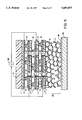
- FIG. 2 shows a partially fragmented cross-section of a multiple layer electrostatic transducer wherein the layers have been perforated in situ and the perforations in each layer are substantially in alignment.
- FIG. 3 shows a partially fragmented cross-section of a multiple layer electrostatic transducer wherein the layers have been perforated ex situ and the perforations in each layer are substantially not in alignment.
- FIG. 4 shows a partially fragmented cross-section of a multiple layer electrostatic transducer wherein elastomeric spacers have been deposited on previously perforated substrates.
- FIG. 5 shows a partially fragmented cross-section of a multiple layer electrostatic transducer similar to that of FIG. 2, but with the stacked "layers" in reversed orientation.
- FIG. 1 shows in cross-section an improved design for an electrostatic transducer of the type described in parent United States Patent Application Ser. No. 08/091,009 (Whitehead).
- first and second electrically conductive sheets 2, 4 are compliantly separated by elastomeric microstructure 3.
- Electrically conductive surface 2 is a thin film of metal (e.g. aluminum) vacuum deposited or laminated onto a polymer (e.g. polyester) carrier film 1.
- An additional protective covering layer 15 may be laminated to carrier film 1 to provide added durability.
- Electrically conductive sheet 4 is a sheet of microporous material bonded to the surface of porous structure 16.
- Porous structure 16 can be manufactured by a number of techniques known in the art such as sintering polymer or metal particles 5 together to leave gas-filled spaces 7 which are in fluidic communication (also known in the art as an open-cell structure).
- Microporous conductive sheet 4 may for example be a finely woven wire cloth or a metal sheet microperforated by some means such as chemical etching. Alternatively, sheet 4 may be a polymer/metal composite which has been perforated or a sintered metal.
- the pore diameter, s, and the spacing between each of pores 14 required to achieve an optimal trade-off between loss of active area of electrode 4 and increased viscous resistance to gas flow can be estimated to first order using available analytical formulations and techniques know in the art. See for example, Skyor, Z., "On the Acoustical Resistance Due to Viscous Losses in the Air Gap of Electrostatic Transducers," Acustica Vol. 19, 1967/68, p. 295-299; or, the discussion in U.S. Pat. No. 4,533,795 (Baumhauer, Jr. et al) beginning at line 60 of column 6.
- Porous structure 16 should be of relatively high porosity to maximize gas reservoir volume for a given thickness of material. However, this must be balanced by the fact that structure 16 should also be substantially rigid and inextensible in the thickness direction so that microporous sheet electrode 4 is substantially stationary relative to foundation 19 (e.g. a wall) to which the transducer is bonded by adhesive layer 18. If electrode 4 is not held stationary relative to foundation 19, then depending on the relative values of the other impedances, the electrostatic force may move electrode 4 instead of electrode 2 and this will lower the performance of the device. This requirement suggests a preference toward rigid materials for porous structure 16. The depth of structure 16 is dependent upon its desired porosity and the effective gas volume per unit area d e required for the particular application.
- the depth of structure 16 is likely to be within the range of 0.1 mm to 10 mm.
- Elastomeric microstructure 3 may be formed on the surface of conductive sheet 2 using proprietary microreplication process technology services available from parties such as 3M Optics Technology Centre, St. Paul, Minn.
- the design of microstructure 3 and selection of elastomer formulation will depend on the performance and manufacturability requirements for a particular application. In general, an elastomer with high resilience and high dielectric strength is preferable from a performance standpoint.
- the gas pocket depth, d is also determined by application requirements. Where high driving pressures are required, the pocket depth will typically be less than the Paschen minimum distance for the gas 8 and gas pressure in order to obtain high dielectric strength as described in U.S. Pat. No. 4,885,783 (Whitehead et al). For air at standard pressure, the Paschen minimum distance is approximately 16 ⁇ m. In applications where less driving pressure is required, and more allowable amplitude would be desirable, larger gaps may be used at the expense of higher operating voltages.
- Elastomeric microstructure 3 may be bonded to surface 4 at interface 6 by a number of suitable adhesive processes such as spray or roll coating of a thin adhesive film (not shown) onto either of elastomeric microstructure or surface 4.
- the adhesive should be able to withstand the dielectric and mechanical stress of the intended application and should be as thin as possible to achieve these objectives so as not to substantially increase the voltage required to operate the device. Also, the adhesive should not substantially block the flow of gas through microperforated electrode 4. If thermo-plastic elastomers are selected for microstructure 3, thermo-plastic bonding may prove to be a desirable method of bonding elastomer 3 to surface 4.
- the transducer just described is operated by connecting one terminal of voltage source 20 to electrode sheet 2 and the other terminal to perforated electrode sheet 4.
- the applied voltage may be similar to that commonly used in the art consisting of a DC bias (V dc ) and an AC signal (V ac ). If V ac is small compared to V dc then the time varying electrostatic force per unit area P e produced will be as follows: ##EQU2## where h is the interelectrode spacing and ⁇ is the electrical permittivity of the dielectric. This electrostatic force per unit area will result in a deformation of elastomeric microstructure 3 and a relative motion between the two electrodes.
- electrode 2 will move in response to signal voltage V ac .
- this motional response will be in approximately linear proportion to the driving signal V ac .
- a number of other driving arrangements may be used, depending upon the particular application.
- the transducer depicted in FIG. 1 is similar in functionality to devices previously described in the parent application U.S. Ser. No. 08/091,009 in that a series of recessed regions of gas pocket depth substantially greater than the interelectrode gas pocket depth are used to increase the effective volume of gas per unit area and hence reduce the dynamic stiffness per unit area of the gas.
- the present design is an improvement in that it appears to be significantly less expensive to construct in order to achieve similar functionality. Nonetheless, the present design is limited to a maximum displacement which is some fraction (e.g. 30%) of the gas pocket thickness.
- FIG. 2 a second embodiment of the present invention which solves this problem of increased mass impedance is shown in cross-section.
- a device is shown similar to that of FIG. 1, with three additional perforated "layers" of transducer.
- Each "layer” consists of a polymer carrier film 1 with a conductive sheet 2 and elastomeric microstructure 3 as described earlier in reference to FIG. 1.
- All “layers”, except the outermost one, are substantially perforated (e.g. greater than 1% open area) to allow communication between the gas contained in gas pockets 8 and porous gas reservoir 16.
- the outermost layer is not substantially perforated, as this would inhibit the ability of the device to produce a localized volumetric displacement of the fluid, which is necessary for propagation of acoustic waves.
- Some degree of perforation in the outermost layer is usually desirable to balance the ambient gas pressure on the exterior of the device with that on the interior. Also, it may be desirable to introduce perforations in order to vary the acoustic output frequency response of the device (see for example U.S. Pat. No. 4,582,163 (Catthoor)). Fluid communication between the gas inside the transducer and the environment at the edges of the transducer is typically prevented by sealing the edges (not shown).
- the electrode sheets in every second layer are connected to one terminal of the power supply, whilst the remainder are connected to the opposite terminal.
- all adjacent electrode sheets are of opposite polarity and will be attracted toward each other upon application of a voltage signal.
- the elastomeric microstructures compliantly spacing the electrode sheets apart deform and compress the gas 8 contained between them, forcing the gas through the perforations in each successive layer and ultimately into porous gas reservoir 16.
- the viscous impedance to this gas flow to and from reservoir 16 should be of the same order or less than the largest other impedance to the motion of the outer (i.e. mobile) surface of the transducer. To achieve this, one must select the correct number, spacing, and cross-sectional area of perforations 14. This can be done using techniques know in the art, as described in the Skyor and Baumhauer, Jr. et al references noted above.
- a preferred method of manufacturing the embodiment shown in FIG. 2 is to first stack and bond the three layers 22, 23, 24. Bonding is achieved with a thin film of adhesive, or alternatively by other means such as thermoplastic fusing, etc.
- This multilayer structure is then perforated by an appropriate perforation technology such as mechanical or hot pin punching, laser ablation, fluid jet punching, electrical discharge (e.g. U.S. Pat. No. 4,777,338), etc.
- the perforated structure 25 is then bonded to the porous structure 16 and the non-perforated top layer 21. Using this method of manufacture, the perforations in each layer are substantially aligned.
- Another method of manufacturing the present invention involves first perforating each individual layer and then bonding them together to form a structure as depicted in cross-section in FIG. 3.
- perforations 14 are substantially misaligned (it would be quite costly to provide a means of registering them into alignment on this size scale and speed of manufacture).
- a third method of manufacturing the present invention is to use a carrier film 1 which has been previously perforated and metallized to form conductive surface 2. Elastomeric spacers 3 are then deposited on surface 2. This results in blockage of only a small number of perforations 14 in those areas where the location of spacers 3 and perforations 14 happen to coincide, as shown in cross-section in FIG. 4.
- the advantage of this method of manufacture is that there are microperforated polymer films available which could be used and could obviate the need for an additional state of manufacturing process.
- FIG. 5 shows yet another method of manufacturing transducers in accordance with the invention.
- the basic design depicted in FIG. 2 is shown but with the stacked "layers" in reversed orientation.
- the FIG. 5 design obviates the need for the lower microperforated electrode 4 seen in FIG. 2, which may afford manufacturing cost advantages in certain applications.
- the "reversed orientation" design depicted in FIG. 5 may be applied to any of the designs hereinbefore described and illustrated.
Abstract
Description
Claims (8)
Priority Applications (1)
| Application Number | Priority Date | Filing Date | Title |
|---|---|---|---|
| US08/525,294 US5682075A (en) | 1993-07-14 | 1995-09-07 | Porous gas reservoir electrostatic transducer |
Applications Claiming Priority (2)
| Application Number | Priority Date | Filing Date | Title |
|---|---|---|---|
| US08/091,009 US5450498A (en) | 1993-07-14 | 1993-07-14 | High pressure low impedance electrostatic transducer |
| US08/525,294 US5682075A (en) | 1993-07-14 | 1995-09-07 | Porous gas reservoir electrostatic transducer |
Related Parent Applications (1)
| Application Number | Title | Priority Date | Filing Date |
|---|---|---|---|
| US08/091,009 Continuation-In-Part US5450498A (en) | 1993-07-14 | 1993-07-14 | High pressure low impedance electrostatic transducer |
Publications (1)
| Publication Number | Publication Date |
|---|---|
| US5682075A true US5682075A (en) | 1997-10-28 |
Family
ID=46202783
Family Applications (1)
| Application Number | Title | Priority Date | Filing Date |
|---|---|---|---|
| US08/525,294 Expired - Fee Related US5682075A (en) | 1993-07-14 | 1995-09-07 | Porous gas reservoir electrostatic transducer |
Country Status (1)
| Country | Link |
|---|---|
| US (1) | US5682075A (en) |
Cited By (46)
| Publication number | Priority date | Publication date | Assignee | Title |
|---|---|---|---|---|
| US6184608B1 (en) | 1998-12-29 | 2001-02-06 | Honeywell International Inc. | Polymer microactuator array with macroscopic force and displacement |
| EP1178597A1 (en) * | 1999-04-14 | 2002-02-06 | NUNUPAROV, Martyn Sergeevich | Electrostatic devices for mechanical blocking |
| EP1193776A2 (en) * | 2000-09-27 | 2002-04-03 | Eastman Kodak Company | Deformable micro-actuator |
| US6426582B1 (en) * | 1999-05-19 | 2002-07-30 | Siemens Aktiengesellschaft | Micromechanical, capacitative ultrasound transducer and method for the manufacture thereof |
| WO2002085065A1 (en) * | 2001-04-11 | 2002-10-24 | Panphonics Oy | Electromechanical transducer and method for transforming energies |
| US20030052570A1 (en) * | 1999-11-25 | 2003-03-20 | Kari Kirjavainen | Electromechanic film and acoustic element |
| US6628040B2 (en) * | 2000-02-23 | 2003-09-30 | Sri International | Electroactive polymer thermal electric generators |
| US20030214199A1 (en) * | 1997-02-07 | 2003-11-20 | Sri International, A California Corporation | Electroactive polymer devices for controlling fluid flow |
| US20040008853A1 (en) * | 1999-07-20 | 2004-01-15 | Sri International, A California Corporation | Electroactive polymer devices for moving fluid |
| US6684469B2 (en) | 2000-07-11 | 2004-02-03 | Honeywell International Inc. | Method for forming an actuator array device |
| US20040140733A1 (en) * | 2003-01-13 | 2004-07-22 | Keller Christopher Guild | Electrostatic actuator with a multiplicity of stacked parallel plates |
| US20050035683A1 (en) * | 2002-01-17 | 2005-02-17 | Heikki Raisanen | Electromechanical transducer element, method for forming an electromechanical transducer element and transducer formed by said method |
| US7064740B2 (en) | 2001-11-09 | 2006-06-20 | Sharp Laboratories Of America, Inc. | Backlit display with improved dynamic range |
| US20060192465A1 (en) * | 2004-03-12 | 2006-08-31 | Sri International, A California Corporation | Mechanical meta-materials |
| US7164284B2 (en) | 2003-12-18 | 2007-01-16 | Sharp Laboratories Of America, Inc. | Dynamic gamma for a liquid crystal display |
| US20070257766A1 (en) * | 2003-11-18 | 2007-11-08 | Richards Robert F | Micro-Transducer and Thermal Switch for Same |
| US7342592B2 (en) | 2004-06-14 | 2008-03-11 | Sharp Laboratories Of America, Inc. | System for reducing crosstalk |
| US20080089002A1 (en) * | 2006-06-05 | 2008-04-17 | Sri International | Electroadhesion |
| US7415121B2 (en) | 2004-10-29 | 2008-08-19 | Sonion Nederland B.V. | Microphone with internal damping |
| WO2008098988A1 (en) * | 2007-02-17 | 2008-08-21 | Bayer Materialscience Ag | Loudspeaker made from films |
| US20080211341A1 (en) * | 2006-06-05 | 2008-09-04 | Sri International | Wall crawling devices |
| US20080245985A1 (en) * | 1999-07-20 | 2008-10-09 | Sri International | Electroactive polymer devices for controlling fluid flow |
| US7602369B2 (en) | 2004-05-04 | 2009-10-13 | Sharp Laboratories Of America, Inc. | Liquid crystal display with colored backlight |
| US20100052469A1 (en) * | 2006-10-30 | 2010-03-04 | Yohko Naruse | Electrostatic acting device |
| US7732974B1 (en) * | 2006-11-15 | 2010-06-08 | Justin Boland | Electrostatic power generator cell and method of manufacture |
| US7777714B2 (en) | 2004-05-04 | 2010-08-17 | Sharp Laboratories Of America, Inc. | Liquid crystal display with adaptive width |
| US7853094B2 (en) | 2006-01-24 | 2010-12-14 | Sharp Laboratories Of America, Inc. | Color enhancement technique using skin color detection |
| US7872631B2 (en) | 2004-05-04 | 2011-01-18 | Sharp Laboratories Of America, Inc. | Liquid crystal display with temporal black point |
| US7898519B2 (en) | 2005-02-17 | 2011-03-01 | Sharp Laboratories Of America, Inc. | Method for overdriving a backlit display |
| NL2003681C2 (en) * | 2009-10-21 | 2011-04-26 | Stichting Materials Innovation Inst M2I | Micro electromechanical switch and method of manufacturing such a micro electromechanical switch. |
| US8050512B2 (en) | 2004-11-16 | 2011-11-01 | Sharp Laboratories Of America, Inc. | High dynamic range images from low dynamic range images |
| US8050511B2 (en) | 2004-11-16 | 2011-11-01 | Sharp Laboratories Of America, Inc. | High dynamic range images from low dynamic range images |
| US8121401B2 (en) | 2006-01-24 | 2012-02-21 | Sharp Labortories of America, Inc. | Method for reducing enhancement of artifacts and noise in image color enhancement |
| US8395577B2 (en) | 2004-05-04 | 2013-03-12 | Sharp Laboratories Of America, Inc. | Liquid crystal display with illumination control |
| JP2014121201A (en) * | 2012-12-18 | 2014-06-30 | Viscas Corp | Lamination type power generator |
| US8941580B2 (en) | 2006-11-30 | 2015-01-27 | Sharp Laboratories Of America, Inc. | Liquid crystal display with area adaptive backlight |
| US9195058B2 (en) | 2011-03-22 | 2015-11-24 | Parker-Hannifin Corporation | Electroactive polymer actuator lenticular system |
| US9231186B2 (en) | 2009-04-11 | 2016-01-05 | Parker-Hannifin Corporation | Electro-switchable polymer film assembly and use thereof |
| US9425383B2 (en) | 2007-06-29 | 2016-08-23 | Parker-Hannifin Corporation | Method of manufacturing electroactive polymer transducers for sensory feedback applications |
| US9553254B2 (en) | 2011-03-01 | 2017-01-24 | Parker-Hannifin Corporation | Automated manufacturing processes for producing deformable polymer devices and films |
| US9590193B2 (en) | 2012-10-24 | 2017-03-07 | Parker-Hannifin Corporation | Polymer diode |
| US9761790B2 (en) | 2012-06-18 | 2017-09-12 | Parker-Hannifin Corporation | Stretch frame for stretching process |
| US9865527B1 (en) | 2016-12-22 | 2018-01-09 | Texas Instruments Incorporated | Packaged semiconductor device having nanoparticle adhesion layer patterned into zones of electrical conductance and insulation |
| US9876160B2 (en) | 2012-03-21 | 2018-01-23 | Parker-Hannifin Corporation | Roll-to-roll manufacturing processes for producing self-healing electroactive polymer devices |
| US9941194B1 (en) | 2017-02-21 | 2018-04-10 | Texas Instruments Incorporated | Packaged semiconductor device having patterned conductance dual-material nanoparticle adhesion layer |
| EP3573349A4 (en) * | 2017-09-29 | 2020-03-25 | Sumitomo Riko Company Limited | Transducer and method for manufacturing same |
Citations (20)
| Publication number | Priority date | Publication date | Assignee | Title |
|---|---|---|---|---|
| US1777170A (en) * | 1928-03-12 | 1930-09-30 | United Reproducers Patents Cor | Acoustic device |
| US2796467A (en) * | 1951-12-12 | 1957-06-18 | Bell Telephone Labor Inc | Directional transducer |
| US2872532A (en) * | 1954-08-26 | 1959-02-03 | Int Standard Electric Corp | Condenser loudspeaker |
| US2975307A (en) * | 1958-01-02 | 1961-03-14 | Ibm | Capacitive prime mover |
| US3136867A (en) * | 1961-09-25 | 1964-06-09 | Ampex | Electrostatic transducer |
| US3544733A (en) * | 1967-06-15 | 1970-12-01 | Minnesota Mining & Mfg | Electrostatic acoustic transducer |
| US3787642A (en) * | 1971-09-27 | 1974-01-22 | Gte Automatic Electric Lab Inc | Electrostatic transducer having resilient electrode |
| US4160881A (en) * | 1977-12-28 | 1979-07-10 | Microtel B.V. | Electret transducers: acoustically transparent backplate of sintered conductive spheres and a thin electret coating; meshlike diaphragm spacing screen overlays apertured electret backplate with screen junctions overlaying the apertures |
| US4322877A (en) * | 1978-09-20 | 1982-04-06 | Minnesota Mining And Manufacturing Company | Method of making piezoelectric polymeric acoustic transducer |
| US4382196A (en) * | 1981-03-16 | 1983-05-03 | Gte Products Corporation | Tape transducer |
| US4533795A (en) * | 1983-07-07 | 1985-08-06 | American Telephone And Telegraph | Integrated electroacoustic transducer |
| US4582163A (en) * | 1983-05-10 | 1986-04-15 | U.S. Philips Corporation | Electro-acoustic transducer with high air permeable diaphragm |
| US4654546A (en) * | 1984-11-20 | 1987-03-31 | Kari Kirjavainen | Electromechanical film and procedure for manufacturing same |
| US4885783A (en) * | 1986-04-11 | 1989-12-05 | The University Of British Columbia | Elastomer membrane enhanced electrostatic transducer |
| US5206557A (en) * | 1990-11-27 | 1993-04-27 | Mcnc | Microelectromechanical transducer and fabrication method |
| US5395592A (en) * | 1993-10-04 | 1995-03-07 | Bolleman; Brent | Acoustic liquid processing device |
| US5434464A (en) * | 1994-05-23 | 1995-07-18 | Mcnc | Unidirectional supporting structure for microelectromechanical transducers |
| US5461272A (en) * | 1993-10-28 | 1995-10-24 | Nippon Mektron, Ltd. | Planar micro-actuator |
| US5485437A (en) * | 1993-02-05 | 1996-01-16 | Discovision Associates | Shock-resistant, electrostatically actuated pick-up for optical recording and playback |
| US5563466A (en) * | 1993-06-07 | 1996-10-08 | Rennex; Brian G. | Micro-actuator |
-
1995
- 1995-09-07 US US08/525,294 patent/US5682075A/en not_active Expired - Fee Related
Patent Citations (20)
| Publication number | Priority date | Publication date | Assignee | Title |
|---|---|---|---|---|
| US1777170A (en) * | 1928-03-12 | 1930-09-30 | United Reproducers Patents Cor | Acoustic device |
| US2796467A (en) * | 1951-12-12 | 1957-06-18 | Bell Telephone Labor Inc | Directional transducer |
| US2872532A (en) * | 1954-08-26 | 1959-02-03 | Int Standard Electric Corp | Condenser loudspeaker |
| US2975307A (en) * | 1958-01-02 | 1961-03-14 | Ibm | Capacitive prime mover |
| US3136867A (en) * | 1961-09-25 | 1964-06-09 | Ampex | Electrostatic transducer |
| US3544733A (en) * | 1967-06-15 | 1970-12-01 | Minnesota Mining & Mfg | Electrostatic acoustic transducer |
| US3787642A (en) * | 1971-09-27 | 1974-01-22 | Gte Automatic Electric Lab Inc | Electrostatic transducer having resilient electrode |
| US4160881A (en) * | 1977-12-28 | 1979-07-10 | Microtel B.V. | Electret transducers: acoustically transparent backplate of sintered conductive spheres and a thin electret coating; meshlike diaphragm spacing screen overlays apertured electret backplate with screen junctions overlaying the apertures |
| US4322877A (en) * | 1978-09-20 | 1982-04-06 | Minnesota Mining And Manufacturing Company | Method of making piezoelectric polymeric acoustic transducer |
| US4382196A (en) * | 1981-03-16 | 1983-05-03 | Gte Products Corporation | Tape transducer |
| US4582163A (en) * | 1983-05-10 | 1986-04-15 | U.S. Philips Corporation | Electro-acoustic transducer with high air permeable diaphragm |
| US4533795A (en) * | 1983-07-07 | 1985-08-06 | American Telephone And Telegraph | Integrated electroacoustic transducer |
| US4654546A (en) * | 1984-11-20 | 1987-03-31 | Kari Kirjavainen | Electromechanical film and procedure for manufacturing same |
| US4885783A (en) * | 1986-04-11 | 1989-12-05 | The University Of British Columbia | Elastomer membrane enhanced electrostatic transducer |
| US5206557A (en) * | 1990-11-27 | 1993-04-27 | Mcnc | Microelectromechanical transducer and fabrication method |
| US5485437A (en) * | 1993-02-05 | 1996-01-16 | Discovision Associates | Shock-resistant, electrostatically actuated pick-up for optical recording and playback |
| US5563466A (en) * | 1993-06-07 | 1996-10-08 | Rennex; Brian G. | Micro-actuator |
| US5395592A (en) * | 1993-10-04 | 1995-03-07 | Bolleman; Brent | Acoustic liquid processing device |
| US5461272A (en) * | 1993-10-28 | 1995-10-24 | Nippon Mektron, Ltd. | Planar micro-actuator |
| US5434464A (en) * | 1994-05-23 | 1995-07-18 | Mcnc | Unidirectional supporting structure for microelectromechanical transducers |
Non-Patent Citations (6)
| Title |
|---|
| Baxandall, P.J., Electrostatic Loudspeakers, in Loudspeaker and Headphone Handbook , 2nd ed., edited by John Borwick (Butterworth Heinemann, Oxford, 1994), Chap. 3. * |
| Baxandall, P.J., Electrostatic Loudspeakers, in Loudspeaker and Headphone Handbook, 2nd ed., edited by John Borwick (Butterworth-Heinemann, Oxford, 1994), Chap. 3. |
| C.R. Hanna, Theory of the Electrostatic Loudspeaker, J. Acoust. Soc. Amer. , vol. II, No. 2, pp. 143 149, 1930. * |
| C.R. Hanna, Theory of the Electrostatic Loudspeaker, J. Acoust. Soc. Amer., vol. II, No. 2, pp. 143-149, 1930. |
| Skvor, Z., On the Acoustical Resistance Due to Viscous Losses in the Air Gap of Electrostatic Transducers, Acustica vol. 19, 1967/68, pp. 295 299. * |
| Skvor, Z., On the Acoustical Resistance Due to Viscous Losses in the Air Gap of Electrostatic Transducers, Acustica vol. 19, 1967/68, pp. 295-299. |
Cited By (99)
| Publication number | Priority date | Publication date | Assignee | Title |
|---|---|---|---|---|
| US20030214199A1 (en) * | 1997-02-07 | 2003-11-20 | Sri International, A California Corporation | Electroactive polymer devices for controlling fluid flow |
| US7320457B2 (en) | 1997-02-07 | 2008-01-22 | Sri International | Electroactive polymer devices for controlling fluid flow |
| US6255758B1 (en) * | 1998-12-29 | 2001-07-03 | Honeywell International Inc. | Polymer microactuator array with macroscopic force and displacement |
| US6184608B1 (en) | 1998-12-29 | 2001-02-06 | Honeywell International Inc. | Polymer microactuator array with macroscopic force and displacement |
| EP1178597A4 (en) * | 1999-04-14 | 2010-08-04 | Martyn Sergeevich Nunuparov | Electrostatic devices for mechanical blocking |
| EP1178597A1 (en) * | 1999-04-14 | 2002-02-06 | NUNUPAROV, Martyn Sergeevich | Electrostatic devices for mechanical blocking |
| US6426582B1 (en) * | 1999-05-19 | 2002-07-30 | Siemens Aktiengesellschaft | Micromechanical, capacitative ultrasound transducer and method for the manufacture thereof |
| US7537197B2 (en) | 1999-07-20 | 2009-05-26 | Sri International | Electroactive polymer devices for controlling fluid flow |
| US7362032B2 (en) | 1999-07-20 | 2008-04-22 | Sri International | Electroactive polymer devices for moving fluid |
| US20040008853A1 (en) * | 1999-07-20 | 2004-01-15 | Sri International, A California Corporation | Electroactive polymer devices for moving fluid |
| US20070164641A1 (en) * | 1999-07-20 | 2007-07-19 | Sri International | Electroactive polymer devices for moving fluid |
| US20090200501A1 (en) * | 1999-07-20 | 2009-08-13 | Sri International | Electroactive polymer devices for controlling fluid flow |
| US7064472B2 (en) | 1999-07-20 | 2006-06-20 | Sri International | Electroactive polymer devices for moving fluid |
| US7394182B2 (en) | 1999-07-20 | 2008-07-01 | Sri International | Electroactive polymer devices for moving fluid |
| US20080245985A1 (en) * | 1999-07-20 | 2008-10-09 | Sri International | Electroactive polymer devices for controlling fluid flow |
| US7971850B2 (en) | 1999-07-20 | 2011-07-05 | Sri International | Electroactive polymer devices for controlling fluid flow |
| US7703742B2 (en) | 1999-07-20 | 2010-04-27 | Sri International | Electroactive polymer devices for controlling fluid flow |
| US20060158065A1 (en) * | 1999-07-20 | 2006-07-20 | Sri International A California Corporation | Electroactive polymer devices for moving fluid |
| US20100176322A1 (en) * | 1999-07-20 | 2010-07-15 | Sri International | Electroactive polymer devices for controlling fluid flow |
| US20030052570A1 (en) * | 1999-11-25 | 2003-03-20 | Kari Kirjavainen | Electromechanic film and acoustic element |
| US6759769B2 (en) * | 1999-11-25 | 2004-07-06 | Kari Kirjavainen | Electromechanic film and acoustic element |
| US20040124738A1 (en) * | 2000-02-23 | 2004-07-01 | Sri International, A California Corporation | Electroactive polymer thermal electric generators |
| US6628040B2 (en) * | 2000-02-23 | 2003-09-30 | Sri International | Electroactive polymer thermal electric generators |
| US20040145277A1 (en) * | 2000-07-11 | 2004-07-29 | Robert Horning | MEMS actuator with lower power consumption and lower cost simplified fabrication |
| US6684469B2 (en) | 2000-07-11 | 2004-02-03 | Honeywell International Inc. | Method for forming an actuator array device |
| EP1193776A3 (en) * | 2000-09-27 | 2005-05-18 | Eastman Kodak Company | Deformable micro-actuator |
| EP1193776A2 (en) * | 2000-09-27 | 2002-04-03 | Eastman Kodak Company | Deformable micro-actuator |
| JP2011030420A (en) * | 2001-04-11 | 2011-02-10 | Panphonics Oy | Electromechanical transducer and method of converting energy |
| US20040113526A1 (en) * | 2001-04-11 | 2004-06-17 | Kari Kirjavainen | Electromechanical transducer and method for transforming energies |
| WO2002085065A1 (en) * | 2001-04-11 | 2002-10-24 | Panphonics Oy | Electromechanical transducer and method for transforming energies |
| US7376239B2 (en) * | 2001-04-11 | 2008-05-20 | Panphonics Oy | Electromechanical transducer and method for transforming energies |
| US7499017B2 (en) | 2001-11-09 | 2009-03-03 | Sharp Laboratories Of America, Inc. | Backlit display with improved dynamic range |
| US7714830B2 (en) | 2001-11-09 | 2010-05-11 | Sharp Laboratories Of America, Inc. | Liquid crystal display backlight with level change |
| US7064740B2 (en) | 2001-11-09 | 2006-06-20 | Sharp Laboratories Of America, Inc. | Backlit display with improved dynamic range |
| US7737936B2 (en) | 2001-11-09 | 2010-06-15 | Sharp Laboratories Of America, Inc. | Liquid crystal display backlight with modulation |
| US7505028B2 (en) | 2001-11-09 | 2009-03-17 | Sharp Laboratories Of America, Inc. | Backlit display with improved dynamic range |
| US7505027B2 (en) | 2001-11-09 | 2009-03-17 | Sharp Laboratories Of America, Inc. | Backlit display with improved dynamic range |
| US7675500B2 (en) | 2001-11-09 | 2010-03-09 | Sharp Laboratories Of America, Inc. | Liquid crystal display backlight with variable amplitude LED |
| US8378955B2 (en) | 2001-11-09 | 2013-02-19 | Sharp Laboratories Of America, Inc. | Liquid crystal display backlight with filtering |
| US20050035683A1 (en) * | 2002-01-17 | 2005-02-17 | Heikki Raisanen | Electromechanical transducer element, method for forming an electromechanical transducer element and transducer formed by said method |
| US7589439B2 (en) | 2002-01-17 | 2009-09-15 | B-Band Oy | Electromechanical transducer element, method for forming an electromechanical transducer element and transducer formed by said method |
| US20040140733A1 (en) * | 2003-01-13 | 2004-07-22 | Keller Christopher Guild | Electrostatic actuator with a multiplicity of stacked parallel plates |
| US20070257766A1 (en) * | 2003-11-18 | 2007-11-08 | Richards Robert F | Micro-Transducer and Thermal Switch for Same |
| US7164284B2 (en) | 2003-12-18 | 2007-01-16 | Sharp Laboratories Of America, Inc. | Dynamic gamma for a liquid crystal display |
| US8436508B2 (en) | 2004-03-12 | 2013-05-07 | Sri International | Mechanical meta-materials |
| WO2005089176A3 (en) * | 2004-03-12 | 2007-06-14 | Stanford Res Inst Int | Mechanical meta-materials |
| US20060192465A1 (en) * | 2004-03-12 | 2006-08-31 | Sri International, A California Corporation | Mechanical meta-materials |
| US20100007240A1 (en) * | 2004-03-12 | 2010-01-14 | Sri International | Mechanical meta-materials |
| US7598652B2 (en) | 2004-03-12 | 2009-10-06 | Sri International | Mechanical meta-materials |
| US8164232B2 (en) | 2004-03-12 | 2012-04-24 | Sri International | Mechanical meta-materials |
| US7598651B2 (en) * | 2004-03-12 | 2009-10-06 | Sri International | Mechanical meta-materials |
| US7602369B2 (en) | 2004-05-04 | 2009-10-13 | Sharp Laboratories Of America, Inc. | Liquid crystal display with colored backlight |
| US8400396B2 (en) | 2004-05-04 | 2013-03-19 | Sharp Laboratories Of America, Inc. | Liquid crystal display with modulation for colored backlight |
| US8395577B2 (en) | 2004-05-04 | 2013-03-12 | Sharp Laboratories Of America, Inc. | Liquid crystal display with illumination control |
| US7777714B2 (en) | 2004-05-04 | 2010-08-17 | Sharp Laboratories Of America, Inc. | Liquid crystal display with adaptive width |
| US7872631B2 (en) | 2004-05-04 | 2011-01-18 | Sharp Laboratories Of America, Inc. | Liquid crystal display with temporal black point |
| US7342592B2 (en) | 2004-06-14 | 2008-03-11 | Sharp Laboratories Of America, Inc. | System for reducing crosstalk |
| US7415121B2 (en) | 2004-10-29 | 2008-08-19 | Sonion Nederland B.V. | Microphone with internal damping |
| US8050511B2 (en) | 2004-11-16 | 2011-11-01 | Sharp Laboratories Of America, Inc. | High dynamic range images from low dynamic range images |
| US8050512B2 (en) | 2004-11-16 | 2011-11-01 | Sharp Laboratories Of America, Inc. | High dynamic range images from low dynamic range images |
| US7898519B2 (en) | 2005-02-17 | 2011-03-01 | Sharp Laboratories Of America, Inc. | Method for overdriving a backlit display |
| US9143657B2 (en) | 2006-01-24 | 2015-09-22 | Sharp Laboratories Of America, Inc. | Color enhancement technique using skin color detection |
| US8121401B2 (en) | 2006-01-24 | 2012-02-21 | Sharp Labortories of America, Inc. | Method for reducing enhancement of artifacts and noise in image color enhancement |
| US7853094B2 (en) | 2006-01-24 | 2010-12-14 | Sharp Laboratories Of America, Inc. | Color enhancement technique using skin color detection |
| US20100027187A1 (en) * | 2006-06-05 | 2010-02-04 | Sri International | Electroadhesion |
| US7551419B2 (en) | 2006-06-05 | 2009-06-23 | Sri International | Electroadhesion |
| US20080089002A1 (en) * | 2006-06-05 | 2008-04-17 | Sri International | Electroadhesion |
| US20110110010A1 (en) * | 2006-06-05 | 2011-05-12 | Sri International | Wall crawling robots |
| US20100271746A1 (en) * | 2006-06-05 | 2010-10-28 | Sri International | Electroadhesive devices |
| US7773363B2 (en) | 2006-06-05 | 2010-08-10 | Sri International | Electroadhesion |
| US8665578B2 (en) | 2006-06-05 | 2014-03-04 | Sri International | Electroadhesive devices |
| US20080211341A1 (en) * | 2006-06-05 | 2008-09-04 | Sri International | Wall crawling devices |
| US8111500B2 (en) | 2006-06-05 | 2012-02-07 | Sri International | Wall crawling robots |
| US20100059298A1 (en) * | 2006-06-05 | 2010-03-11 | Sri International | Wall crawling robots |
| US8125758B2 (en) | 2006-06-05 | 2012-02-28 | Sri International | Electroadhesive devices |
| US7872850B2 (en) | 2006-06-05 | 2011-01-18 | Sri International | Wall crawling robots |
| US7554787B2 (en) | 2006-06-05 | 2009-06-30 | Sri International | Wall crawling devices |
| US20100052469A1 (en) * | 2006-10-30 | 2010-03-04 | Yohko Naruse | Electrostatic acting device |
| US8089194B2 (en) * | 2006-10-30 | 2012-01-03 | Sanyo Electric Co., Ltd. | Electrostatic acting device including an electret film and an electrostatic power generator including an electret film |
| US7732974B1 (en) * | 2006-11-15 | 2010-06-08 | Justin Boland | Electrostatic power generator cell and method of manufacture |
| US8941580B2 (en) | 2006-11-30 | 2015-01-27 | Sharp Laboratories Of America, Inc. | Liquid crystal display with area adaptive backlight |
| WO2008098988A1 (en) * | 2007-02-17 | 2008-08-21 | Bayer Materialscience Ag | Loudspeaker made from films |
| US9425383B2 (en) | 2007-06-29 | 2016-08-23 | Parker-Hannifin Corporation | Method of manufacturing electroactive polymer transducers for sensory feedback applications |
| US9231186B2 (en) | 2009-04-11 | 2016-01-05 | Parker-Hannifin Corporation | Electro-switchable polymer film assembly and use thereof |
| NL2003681C2 (en) * | 2009-10-21 | 2011-04-26 | Stichting Materials Innovation Inst M2I | Micro electromechanical switch and method of manufacturing such a micro electromechanical switch. |
| US9553254B2 (en) | 2011-03-01 | 2017-01-24 | Parker-Hannifin Corporation | Automated manufacturing processes for producing deformable polymer devices and films |
| US9195058B2 (en) | 2011-03-22 | 2015-11-24 | Parker-Hannifin Corporation | Electroactive polymer actuator lenticular system |
| US9876160B2 (en) | 2012-03-21 | 2018-01-23 | Parker-Hannifin Corporation | Roll-to-roll manufacturing processes for producing self-healing electroactive polymer devices |
| US9761790B2 (en) | 2012-06-18 | 2017-09-12 | Parker-Hannifin Corporation | Stretch frame for stretching process |
| US9590193B2 (en) | 2012-10-24 | 2017-03-07 | Parker-Hannifin Corporation | Polymer diode |
| JP2014121201A (en) * | 2012-12-18 | 2014-06-30 | Viscas Corp | Lamination type power generator |
| US9865527B1 (en) | 2016-12-22 | 2018-01-09 | Texas Instruments Incorporated | Packaged semiconductor device having nanoparticle adhesion layer patterned into zones of electrical conductance and insulation |
| US10354890B2 (en) | 2016-12-22 | 2019-07-16 | Texas Instruments Incorporated | Packaged semiconductor device having nanoparticle adhesion layer patterned into zones of electrical conductance and insulation |
| US10636679B2 (en) | 2016-12-22 | 2020-04-28 | Texas Instruments Incorporated | Packaged semiconductor device having nanoparticle adhesion layer patterned into zones of electrical conductance and insulation |
| US9941194B1 (en) | 2017-02-21 | 2018-04-10 | Texas Instruments Incorporated | Packaged semiconductor device having patterned conductance dual-material nanoparticle adhesion layer |
| US10573586B2 (en) | 2017-02-21 | 2020-02-25 | Texas Instruments Incorporated | Packaged semiconductor device having patterned conductance dual-material nanoparticle adhesion layer |
| EP3573349A4 (en) * | 2017-09-29 | 2020-03-25 | Sumitomo Riko Company Limited | Transducer and method for manufacturing same |
| CN110959295A (en) * | 2017-09-29 | 2020-04-03 | 住友理工株式会社 | Transducer and method of manufacturing the same |
| US11750981B2 (en) | 2017-09-29 | 2023-09-05 | Sumitomo Riko Company Limited | Transducer and method for manufacturing same |
Similar Documents
| Publication | Publication Date | Title |
|---|---|---|
| US5682075A (en) | Porous gas reservoir electrostatic transducer | |
| EP0708689B1 (en) | High pressure low impedance electrostatic transducer | |
| CA1114492A (en) | Piezoelectric high polymer, multilayer electro-acoustic transducers | |
| CA2081038C (en) | Electret transducer array and fabrication technique | |
| Heydt et al. | Acoustical performance of an electrostrictive polymer film loudspeaker | |
| JP5761192B2 (en) | Oscillator and electronic device | |
| EP1042822B1 (en) | Piezoelectric transducer and method of use | |
| CN100470867C (en) | Piezoelectric ceramic element and portable device | |
| CA1071750A (en) | Transducer having piezoelectric film arranged with alternating curvatures | |
| US6825593B2 (en) | Piezoelectric type electric acoustic converter | |
| US7493821B2 (en) | Micromachined acoustic transducer and method of operating the same | |
| EP2597892A1 (en) | Vibration device | |
| US6349141B1 (en) | Dual bi-laminate polymer audio transducer | |
| EP1060637B1 (en) | Acoustic element | |
| EP1323330B1 (en) | Electrostatic audio loudspeakers | |
| JP3714128B2 (en) | Piezoelectric electroacoustic transducer | |
| CA1165431A (en) | Acoustic transducer with adjacent piezoelectric polymer films physically connected at their centres | |
| JP3395672B2 (en) | Piezoelectric electroacoustic transducer | |
| EP2590435A1 (en) | Vibration device | |
| JP3246685B2 (en) | Electroacoustic transducer | |
| CN218634295U (en) | Microphone assembly and electronic equipment | |
| JPS6130899A (en) | Piezoelectric speaker | |
| CN117729500A (en) | Acoustic piezoelectric structure, acoustic sensor and electronic equipment | |
| JPS60241399A (en) | Underwater sound wave transmitter | |
| Corsaro et al. | Dual bi-laminate polymer audio transducer |
Legal Events
| Date | Code | Title | Description |
|---|---|---|---|
| AS | Assignment |
Owner name: UNIVERSITY OF BRITISH COLUMBIA, THE, CANADA Free format text: ASSIGNMENT OF ASSIGNORS INTEREST;ASSIGNORS:BOLLEMAN, BRENT J.;WHITEHEAD, LORNE A.;REEL/FRAME:007652/0327;SIGNING DATES FROM 19950831 TO 19950905 |
|
| FEPP | Fee payment procedure |
Free format text: PAYOR NUMBER ASSIGNED (ORIGINAL EVENT CODE: ASPN); ENTITY STATUS OF PATENT OWNER: LARGE ENTITY |
|
| AS | Assignment |
Owner name: SONIGISTIX CORPORATION, CANADA Free format text: ASSIGNMENT OF ASSIGNORS INTEREST;ASSIGNOR:BRITISH COLUMBIA, UNIVERSITY OF, THE;REEL/FRAME:010437/0024 Effective date: 19990707 |
|
| FPAY | Fee payment |
Year of fee payment: 4 |
|
| AS | Assignment |
Owner name: LEVEL 9 SOUND DESIGNS INC., CANADA Free format text: CHANGE OF NAME;ASSIGNOR:627054 B.C. LTD.;REEL/FRAME:012343/0112 Effective date: 20011122 Owner name: 627054 B.C. LTD., CANADA Free format text: ASSIGNMENT OF ASSIGNORS INTEREST;ASSIGNOR:SONIGISTIX CORPORATION BY WOLRIGE MAHON LIMITED;REEL/FRAME:012343/0117 Effective date: 20011102 |
|
| AS | Assignment |
Owner name: SPECTRUM ATG CORPORATION, CALIFORNIA Free format text: EXCLUSIVE LICENSE;ASSIGNOR:SONIGISTIX CORPORATION;REEL/FRAME:012683/0770 Effective date: 20010125 Owner name: FOCUSED LINEAR ARRAY TECHNOLOGY, INC., CALIFORNIA Free format text: EXCLUSIVE LICENSE;ASSIGNOR:SONIGISTIX CORPORATION;REEL/FRAME:012683/0770 Effective date: 20010125 |
|
| FPAY | Fee payment |
Year of fee payment: 8 |
|
| SULP | Surcharge for late payment |
Year of fee payment: 7 |
|
| FEPP | Fee payment procedure |
Free format text: PAT HOLDER NO LONGER CLAIMS SMALL ENTITY STATUS, ENTITY STATUS SET TO UNDISCOUNTED (ORIGINAL EVENT CODE: STOL); ENTITY STATUS OF PATENT OWNER: LARGE ENTITY |
|
| REFU | Refund |
Free format text: REFUND - PAYMENT OF MAINTENANCE FEE, 8TH YR, SMALL ENTITY (ORIGINAL EVENT CODE: R2552); ENTITY STATUS OF PATENT OWNER: LARGE ENTITY |
|
| AS | Assignment |
Owner name: SOUND CHEERS LIMITED, VIRGIN ISLANDS, BRITISH Free format text: ASSIGNMENT OF ASSIGNORS INTEREST;ASSIGNOR:LEVEL 9 SOUND DESIGNS INC.;REEL/FRAME:017325/0018 Effective date: 20051202 |
|
| FEPP | Fee payment procedure |
Free format text: PAYER NUMBER DE-ASSIGNED (ORIGINAL EVENT CODE: RMPN); ENTITY STATUS OF PATENT OWNER: LARGE ENTITY Free format text: PAYOR NUMBER ASSIGNED (ORIGINAL EVENT CODE: ASPN); ENTITY STATUS OF PATENT OWNER: LARGE ENTITY |
|
| REMI | Maintenance fee reminder mailed | ||
| LAPS | Lapse for failure to pay maintenance fees | ||
| STCH | Information on status: patent discontinuation |
Free format text: PATENT EXPIRED DUE TO NONPAYMENT OF MAINTENANCE FEES UNDER 37 CFR 1.362 |
|
| FP | Lapsed due to failure to pay maintenance fee |
Effective date: 20091028 |