US5687453A - Grounding washer and arrangements for conductive hinge joints - Google Patents
Grounding washer and arrangements for conductive hinge joints Download PDFInfo
- Publication number
- US5687453A US5687453A US08/422,461 US42246195A US5687453A US 5687453 A US5687453 A US 5687453A US 42246195 A US42246195 A US 42246195A US 5687453 A US5687453 A US 5687453A
- Authority
- US
- United States
- Prior art keywords
- hinge
- rivet
- washer
- components
- head
- Prior art date
- Legal status (The legal status is an assumption and is not a legal conclusion. Google has not performed a legal analysis and makes no representation as to the accuracy of the status listed.)
- Expired - Lifetime
Links
Images

Classifications
-
- E—FIXED CONSTRUCTIONS
- E05—LOCKS; KEYS; WINDOW OR DOOR FITTINGS; SAFES
- E05D—HINGES OR SUSPENSION DEVICES FOR DOORS, WINDOWS OR WINGS
- E05D11/00—Additional features or accessories of hinges
- E05D11/0081—Additional features or accessories of hinges for transmitting energy, e.g. electrical cable routing
-
- E—FIXED CONSTRUCTIONS
- E05—LOCKS; KEYS; WINDOW OR DOOR FITTINGS; SAFES
- E05Y—INDEXING SCHEME RELATING TO HINGES OR OTHER SUSPENSION DEVICES FOR DOORS, WINDOWS OR WINGS AND DEVICES FOR MOVING WINGS INTO OPEN OR CLOSED POSITION, CHECKS FOR WINGS AND WING FITTINGS NOT OTHERWISE PROVIDED FOR, CONCERNED WITH THE FUNCTIONING OF THE WING
- E05Y2900/00—Application of doors, windows, wings or fittings thereof
- E05Y2900/50—Application of doors, windows, wings or fittings thereof for vehicles
- E05Y2900/53—Application of doors, windows, wings or fittings thereof for vehicles characterised by the type of wing
- E05Y2900/536—Hoods
-
- Y—GENERAL TAGGING OF NEW TECHNOLOGICAL DEVELOPMENTS; GENERAL TAGGING OF CROSS-SECTIONAL TECHNOLOGIES SPANNING OVER SEVERAL SECTIONS OF THE IPC; TECHNICAL SUBJECTS COVERED BY FORMER USPC CROSS-REFERENCE ART COLLECTIONS [XRACs] AND DIGESTS
- Y10—TECHNICAL SUBJECTS COVERED BY FORMER USPC
- Y10S—TECHNICAL SUBJECTS COVERED BY FORMER USPC CROSS-REFERENCE ART COLLECTIONS [XRACs] AND DIGESTS
- Y10S439/00—Electrical connectors
- Y10S439/927—Conductive gasket
Definitions
- the present invention relates to grounding washers and arrangements for conductive hinge joints. More particularly, the present invention relates to a grounding washer configuration and arrangements for conductive hinge joints employed in automotive body structures.
- the hood covering the engine compartment of the vehicle is grounded to the automotive body through a hinge which pivots the hood.
- a ground strap is used to ground the hood to the body. Ground straps have a number of problems including high cost, packaging concerns, and problems with durability and reliability.
- the present invention is directed to a washer for use in a conductive hinge to allow conduction of electrical potential between first and second hinge elements connected by a pin.
- the washer comprises generally annular skirt formed on the washer, the skirt being deflected away from a plane to form a concavity with a peripheral edge for engaging one of the hinged members.
- the washer also has an inner portion extending toward a through hole through in which the pin is received, the inner portion having a surface for engaging the second hinge component.
- the present invention is directed to an arrangement for a conductive hinge joint wherein the hinge joint comprises first and second components which are to be electrically connected to one another proximate pivot holes through the hinge components joined by a connecting pin.
- the connecting pin is a rivet having a first head for abutting a first surface of the first hinge component and a second head for abutting a first surface of the second hinge component to hold the hinge components in pivotal relationship with respect to one another.
- the rivet includes a stop portion extending from the first head toward the second head for engaging the second hinge component to keep the first and second hinge components in spaced relation to one another while the rivet is set to form the second head.
- the rivet further includes a shank portion extending through the pivot hole in the second hinge component.
- a conductive washer is disposed around the rivet between the first and second hinge components. The conductive washer is spring loaded upon forming the second end of the rivet so as to be under a constant load to maintain electrical contact between the first and second hinge components.
- an automotive vehicle having a radio includes a metal body having an engine compartment enclosed by a hood pivoted to the body with a metal hinge, the metal hinge including a first hinge component fixed to the hood and a second hinge component fixed to the body.
- the hinge components pivot with respect to one another about a pin received through openings in the hinge components.
- the improvement comprises a conductive element disposed between the hinge components and around the pin. The conductive element is loaded so as to be in constant contact with both hinge components to ground the hood to the automotive body so as to suppress noise in the radio which would occur if the hood were ungrounded.
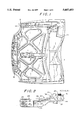
- FIG. 1 is a top view, with portions deleted, of a portion of an automobile body showing a cowl, fender, load beam and hood;
- FIG. 2 is an enlarged side view of a hinge employed to hinge the hood of FIG. 1 to the load beam or other body member of FIG. 1;
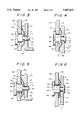
- FIG. 3 is an enlarged elevational view of a washer and rivet employed in combination with the hinge of FIG. 2 prior to setting the rivet;
- FIG. 4 is an enlarged elevational view similar to FIG. 3 but subsequent to setting the rivet;
- FIG. 5 is an enlarged elevational view of a second embodiment of the rivet and washer combination prior to setting the rivet;
- FIG. 6 is an enlarged elevational view similar to FIG. 5 but subsequent to setting the rivet
- FIG. 7 is an enlarged front view of a grounding washer configured in accordance
- FIG. 8 is an elevation through the washer of FIG. 6 taken along lines 8--8 of FIG. 7;
- FIG. 9 is a front view of the washer of FIGS. 6-8 with the washer shown in actual size.
- FIG. 1 there is shown portions of an automotive vehicle body including a cowl structure and dash panel 10 which houses a radio 12.
- a load beam 14 supports a fender 16 and a hood 18 which covers the engine compartment (not shown) of the vehicle.
- a hinge 20 generally of a conventional hinge structure, which hinges the hood 18 to the load beam 14.
- the hinge 20 includes an arm 22 which is unitary with an attachment plate 24.
- the attachment plate 24 has three bolt holes 26 which receive bolts that are bolted to the hood 18.
- the arm 22 and plate 24 form a first component 28 of the hinge 20.
- the first component 28 has a first pivot hole 29 therethrough.
- a second component 30 of the hinge 20 includes a plate 32 which is bolted through bolt holes 34 to the load beam 14 or to some other body structure of the vehicle.
- the second component 30 has a pivot hole 31 therethrough.
- a conductive hinge joint assembly 40 is utilized to join the first hinge component 28 to the second hinge component 30.
- the hinge joint assembly is comprised of a pin, preferably in the form of a rivet 42 which is received through the pivot holes 29 and 31 and through a center hole 43 of a conductive washer 44.
- the conductive washer 44 establishes a grounding path between the hinge component 28, connected to the hood 18 of the automobile (see FIG. 1) and the second hinge component 30, connected to the load beam 14 of the automobile body (see FIG. 1).
- FIG. 3 shows the hinge joint assembly 40 prior to the rivet 42 being set and
- FIG. 4 shows the hinge joint assembly after the rivet has been set.
- the rivet 42 has a head 46 which is larger than the pivot hole 29 through the hinge component 28 and a stepped portion 50 which has a diameter less than the pivot hole 29 so as to be received through the pivot hole.
- the stepped portion 50 has an axial length slightly greater (by about 0.2 mm) than the thickness of the first hinge component 28 proximate the pivot hole 29 and a diameter less than the diameter of the pivot hole 31 through the second hinge component 30 so that when the rivet 42 is set a gap 51 (FIG. 4) remains between the first and second hinge components.
- a shank portion 52 of the rivet 42 projects through the second pivot hole 31 in the hinge component 30. As is shown in FIG.
- the end of the shank 52 is set or flattened to form a head 56 having a diameter greater than the second pivot hole 31 so as to permanently join the first and second hinge components 28 and 30 to one another in a pivotal relationship.
- the washer 44 is slightly deformed as it is squeezed between the annular shoulder 57 and the surface 58 of the hinge member 30 so that it establishes metal-to-metal contact with the surface 58 at locations 59. Moreover, the washer 44 deflects where it contacts surface 60 of hinge member 28 and establishes metal-to-metal contact at an annular line 61. An electrical grounding path is therefore established between contact locations 61 and 57 on hinge members 28 and 30 through washer 44 effectively grounding the radio 12 to the hood 18.
- the rivet 42 is TEFLON® coated to provide permanent dry lubrication which will not interfere with the electrical connection between the first and second hinge components 28 and 30 provided by the washer 44.
- FIGS. 5 and 6 there is shown a second embodiment of the invention wherein, instead of coating the rivet 42 with TEFLON®, a TEFLON® bushing 65 is disposed in the hole 29 through the hinge component 28 so that the hinge component 28 rotates freely on the rivet 42.
- the second embodiment functions substantially the same as the first embodiment in which setting of the rivet 42 by forming the rivet head 56 (FIG. 6) causes deflection and stressing of the washer 44 so as to establish continuous electrical grounding through the washer due to contact between the contact locations 61 and 57.
- the washer 44 configured in accordance with the present invention is illustrated substantially enlarged.
- the washer 44 is concave, and at side 75 facing the second hinge component 30, the washer is convex.
- the washer 44 has an outer area 80 formed as a skirt with a peripheral edge 82 for abutting the first hinge component 28 at locations 61 (see FIGS. 4 and 6) and an inner area 84 with a plurality of radially extending teeth 85 terminating in end edges 86 for abutting the second hinge component 30 at locations 59 (see FIGS. 4 and 6).
- the teeth 85 are twisted or skewed about 45° so that side edges 87 thereof extend obliquely with respect to the axis 88 of the washer.
- the outer area or skirt 80 can have radial cuts 90 therein which facilitate bending the outer area 80 at locations 91.
- the bend is approximately 8°-20° and is sufficient to always place the washer 44 under a compressive load after the rivet 42 is set.
- the washer 44 is made of 1/2 hardened brass.
- the washer 44 may be made of beryllium copper or phosphor bronze.
- the washer 44 is about 0.25 to 0.30 mm thick, and as seen in FIG. 9, has a diameter of approximately 20.5 mm (which is the diameter of the undeformed blank).
Abstract
Description
Claims (7)
Priority Applications (1)
| Application Number | Priority Date | Filing Date | Title |
|---|---|---|---|
| US08/422,461 US5687453A (en) | 1995-04-17 | 1995-04-17 | Grounding washer and arrangements for conductive hinge joints |
Applications Claiming Priority (1)
| Application Number | Priority Date | Filing Date | Title |
|---|---|---|---|
| US08/422,461 US5687453A (en) | 1995-04-17 | 1995-04-17 | Grounding washer and arrangements for conductive hinge joints |
Publications (1)
| Publication Number | Publication Date |
|---|---|
| US5687453A true US5687453A (en) | 1997-11-18 |
Family
ID=23674985
Family Applications (1)
| Application Number | Title | Priority Date | Filing Date |
|---|---|---|---|
| US08/422,461 Expired - Lifetime US5687453A (en) | 1995-04-17 | 1995-04-17 | Grounding washer and arrangements for conductive hinge joints |
Country Status (1)
| Country | Link |
|---|---|
| US (1) | US5687453A (en) |
Cited By (32)
| Publication number | Priority date | Publication date | Assignee | Title |
|---|---|---|---|---|
| US5806619A (en) * | 1996-07-29 | 1998-09-15 | Chrysler Corporation | System for providing electrical ground path and shielding electromagnetic waves emitted from an engine compartment |
| US6239360B1 (en) * | 1998-06-09 | 2001-05-29 | Toyoda Gosei Co., Ltd. | Grounding structure for electromagnetic wave shield |
| US6600632B1 (en) * | 2000-01-19 | 2003-07-29 | Maxtor Corporation | Conductive lock washer |
| US6705635B2 (en) * | 2001-08-01 | 2004-03-16 | Autoliv Asp, Inc. | Apparatus and method for rapidly fastening an airbag apparatus |
| US6939097B2 (en) | 2002-11-21 | 2005-09-06 | Illinois Tool Works, Inc. | Ground washer |
| US6951467B1 (en) * | 2004-07-08 | 2005-10-04 | The United States Of America As Represented By The Secretary Of The Army | Conductive rivet for circuit card |
| US20060057864A1 (en) * | 2004-09-13 | 2006-03-16 | Joseph Jeffrey A | Rotative electrical coupling |
| US20060086382A1 (en) * | 2004-02-13 | 2006-04-27 | Plaisted Joshua R | Mechanism for mounting solar modules |
| US20060118163A1 (en) * | 2004-02-13 | 2006-06-08 | Kineo Design Group, Llc | Rack assembly for mounting solar modules |
| US20060237950A1 (en) * | 2005-01-14 | 2006-10-26 | Worrell Barry C | Apparatus and method for attaching a side airbag |
| US7131867B1 (en) * | 2005-05-06 | 2006-11-07 | Pacific Aerospace & Electronics, Inc. | RF connectors having ground springs |
| US20060275098A1 (en) * | 2005-06-03 | 2006-12-07 | Frederic Kramer | Washer with crush zone |
| US20070117417A1 (en) * | 2003-02-24 | 2007-05-24 | O'brien Brenton | Pcb connector |
| US20070251567A1 (en) * | 2004-02-13 | 2007-11-01 | Plaisted Joshua R | Interconnected solar module design and system |
| US20080053517A1 (en) * | 2006-08-31 | 2008-03-06 | Joshua Reed Plaisted | Technique for electrically bonding solar modules and mounting assemblies |
| US20080061599A1 (en) * | 2006-09-07 | 2008-03-13 | Scambia Industrial Developments Aktiengesellschaft | Windbreak device |
| US20080121273A1 (en) * | 2006-11-29 | 2008-05-29 | Joshua Reed Plaisted | Mounting assembly for arrays and other surface-mounted equipment |
| US20090038668A1 (en) * | 2007-08-08 | 2009-02-12 | Joshua Reed Plaisted | Topologies, systems and methods for control of solar energy supply systems |
| US20090211806A1 (en) * | 2008-02-26 | 2009-08-27 | H-Tech, Llc | Electronic assembly including rf feedthrough connector and related methods |
| US20090230713A1 (en) * | 2008-03-13 | 2009-09-17 | Edscha North America | Link system and method therefor |
| US20100157554A1 (en) * | 2008-12-24 | 2010-06-24 | Chih-Kang Ho | Fixing mechanism capable of reducing electromagnetic radiation interference |
| US20110005152A1 (en) * | 2006-09-06 | 2011-01-13 | Pvt Solar, Inc. | Strut runner member and assembly using same for mounting arrays on rooftops and other structures |
| US20120117759A1 (en) * | 2006-03-16 | 2012-05-17 | Securistyle Limited | Hinge Link Pivot Assembly |
| US20130015612A1 (en) * | 2011-07-11 | 2013-01-17 | Schaeffler Technologies AG & Co. KG | Riveted diaphragm spring hysteresis package |
| US20130209161A1 (en) * | 2012-02-09 | 2013-08-15 | Bae Industries, Inc. | Washer with collapsible protrusions for accommodating pivot gap material thickness |
| US20130223015A1 (en) * | 2012-02-27 | 2013-08-29 | Mitsuyoshi Takao | Electronic apparatus, support device, and attachment structure |
| US8595901B1 (en) | 2012-11-02 | 2013-12-03 | Ventra Group, Inc. | Hinge assembly with an adjustable pivot |
| US8768574B1 (en) | 2013-02-22 | 2014-07-01 | Ventra Group, Inc. | Pedestrian protection vehicle hood hinge assembly |
| CN104675243A (en) * | 2013-12-03 | 2015-06-03 | 北京真金昌汽车科技有限公司 | Movable hinge device for automobile engine hood with double-rivet structure |
| US20150330472A1 (en) * | 2014-05-16 | 2015-11-19 | Toyota Jidosha Kabushiki Kaisha | Attachment structure for urging member |
| US20230030015A1 (en) * | 2020-05-07 | 2023-02-02 | Julius Blum Gmbh | Furniture fitting |
| US20230138233A1 (en) * | 2021-10-29 | 2023-05-04 | Anthony DeCarmine | Fastener Assembly and Method of Use |
Citations (24)
| Publication number | Priority date | Publication date | Assignee | Title |
|---|---|---|---|---|
| US779751A (en) * | 1904-04-23 | 1905-01-10 | Henry M Waitt | Washer. |
| CH133437A (en) * | 1927-05-20 | 1929-06-15 | Auguste Mottaz Edouard | Extendable cap. |
| US1959982A (en) * | 1933-02-07 | 1934-05-22 | Electrostatic Omega Corp | Static eliminator |
| US2747166A (en) * | 1954-12-13 | 1956-05-22 | Collins Radio Co | Interlocked flexible contact assembly for shaft |
| FR1156224A (en) * | 1955-09-27 | 1958-05-13 | Illinois Tool Works | Washer |
| US2836688A (en) * | 1956-02-10 | 1958-05-27 | Westinghouse Electric Corp | Electric device |
| US2895033A (en) * | 1955-06-17 | 1959-07-14 | Gen Electric | Current-carrying hinge construction |
| US2994907A (en) * | 1959-08-24 | 1961-08-08 | Ford Motor Co | Hinge device |
| US3054137A (en) * | 1960-08-25 | 1962-09-18 | Ford Motor Co | Hinge device |
| US3103398A (en) * | 1963-09-10 | Door hinge for electrical connection | ||
| US3362737A (en) * | 1965-06-17 | 1968-01-09 | Westinghouse Electric Corp | Fastening arrangement |
| US3431590A (en) * | 1966-12-19 | 1969-03-11 | Amerock Corp | Hinge |
| US3914001A (en) * | 1973-12-26 | 1975-10-21 | Reynolds Metals Co | Electrical grounding apparatus and method and washer for use therewith |
| DE2551404A1 (en) * | 1975-11-15 | 1977-05-26 | Kerpenwerk Gmbh | Articulated welding machine connector - with hinged clevis and tenon joints and adequate spring loaded contact surfaces in joints |
| US4135694A (en) * | 1977-05-16 | 1979-01-23 | Donnelly Mirrors, Inc. | Pivot support bracket |
| US4526432A (en) * | 1979-12-26 | 1985-07-02 | Lockheed Corporation | Electrical connector assembly for flat cables |
| US4734994A (en) * | 1986-12-22 | 1988-04-05 | Gte Valeron Corporation | Probe having a plurality of hinged plates |
| JPS63163017A (en) * | 1986-12-25 | 1988-07-06 | Johnan Seisakusho Co Ltd | Hinge device |
| US4827378A (en) * | 1988-06-15 | 1989-05-02 | Rockwell International Corporation | Jack coaxial connector EMI shielding apparatus |
| US4927367A (en) * | 1988-03-15 | 1990-05-22 | Bull Hn Information Systems Italia S.P.A. | Selective grounding device for electronic equipment |
| US4943247A (en) * | 1989-05-31 | 1990-07-24 | Amp Incorporated | Annular electrical terminal |
| US5001659A (en) * | 1988-12-12 | 1991-03-19 | Nec Corporation | Structure for connecting a rotatable body to a stationary body |
| US5173837A (en) * | 1990-10-15 | 1992-12-22 | Compaq Computer Corporation | Hinge with two-towed clutch spring for suppressing electromagnetic interference for laptop personal computers |
| US5212907A (en) * | 1992-10-13 | 1993-05-25 | Ed Van Sandt | Door including electrical device and pivotable conductor therefor |
-
1995
- 1995-04-17 US US08/422,461 patent/US5687453A/en not_active Expired - Lifetime
Patent Citations (24)
| Publication number | Priority date | Publication date | Assignee | Title |
|---|---|---|---|---|
| US3103398A (en) * | 1963-09-10 | Door hinge for electrical connection | ||
| US779751A (en) * | 1904-04-23 | 1905-01-10 | Henry M Waitt | Washer. |
| CH133437A (en) * | 1927-05-20 | 1929-06-15 | Auguste Mottaz Edouard | Extendable cap. |
| US1959982A (en) * | 1933-02-07 | 1934-05-22 | Electrostatic Omega Corp | Static eliminator |
| US2747166A (en) * | 1954-12-13 | 1956-05-22 | Collins Radio Co | Interlocked flexible contact assembly for shaft |
| US2895033A (en) * | 1955-06-17 | 1959-07-14 | Gen Electric | Current-carrying hinge construction |
| FR1156224A (en) * | 1955-09-27 | 1958-05-13 | Illinois Tool Works | Washer |
| US2836688A (en) * | 1956-02-10 | 1958-05-27 | Westinghouse Electric Corp | Electric device |
| US2994907A (en) * | 1959-08-24 | 1961-08-08 | Ford Motor Co | Hinge device |
| US3054137A (en) * | 1960-08-25 | 1962-09-18 | Ford Motor Co | Hinge device |
| US3362737A (en) * | 1965-06-17 | 1968-01-09 | Westinghouse Electric Corp | Fastening arrangement |
| US3431590A (en) * | 1966-12-19 | 1969-03-11 | Amerock Corp | Hinge |
| US3914001A (en) * | 1973-12-26 | 1975-10-21 | Reynolds Metals Co | Electrical grounding apparatus and method and washer for use therewith |
| DE2551404A1 (en) * | 1975-11-15 | 1977-05-26 | Kerpenwerk Gmbh | Articulated welding machine connector - with hinged clevis and tenon joints and adequate spring loaded contact surfaces in joints |
| US4135694A (en) * | 1977-05-16 | 1979-01-23 | Donnelly Mirrors, Inc. | Pivot support bracket |
| US4526432A (en) * | 1979-12-26 | 1985-07-02 | Lockheed Corporation | Electrical connector assembly for flat cables |
| US4734994A (en) * | 1986-12-22 | 1988-04-05 | Gte Valeron Corporation | Probe having a plurality of hinged plates |
| JPS63163017A (en) * | 1986-12-25 | 1988-07-06 | Johnan Seisakusho Co Ltd | Hinge device |
| US4927367A (en) * | 1988-03-15 | 1990-05-22 | Bull Hn Information Systems Italia S.P.A. | Selective grounding device for electronic equipment |
| US4827378A (en) * | 1988-06-15 | 1989-05-02 | Rockwell International Corporation | Jack coaxial connector EMI shielding apparatus |
| US5001659A (en) * | 1988-12-12 | 1991-03-19 | Nec Corporation | Structure for connecting a rotatable body to a stationary body |
| US4943247A (en) * | 1989-05-31 | 1990-07-24 | Amp Incorporated | Annular electrical terminal |
| US5173837A (en) * | 1990-10-15 | 1992-12-22 | Compaq Computer Corporation | Hinge with two-towed clutch spring for suppressing electromagnetic interference for laptop personal computers |
| US5212907A (en) * | 1992-10-13 | 1993-05-25 | Ed Van Sandt | Door including electrical device and pivotable conductor therefor |
Non-Patent Citations (1)
| Title |
|---|
| U.K Patent Application No. 2,203,484 A; Pub. 19 Oct. 1988 Inventor: Prentler. * |
Cited By (57)
| Publication number | Priority date | Publication date | Assignee | Title |
|---|---|---|---|---|
| US5806619A (en) * | 1996-07-29 | 1998-09-15 | Chrysler Corporation | System for providing electrical ground path and shielding electromagnetic waves emitted from an engine compartment |
| US6239360B1 (en) * | 1998-06-09 | 2001-05-29 | Toyoda Gosei Co., Ltd. | Grounding structure for electromagnetic wave shield |
| US6600632B1 (en) * | 2000-01-19 | 2003-07-29 | Maxtor Corporation | Conductive lock washer |
| US6665140B1 (en) | 2000-01-19 | 2003-12-16 | Maxtor Corporation | Conductive lock washer |
| US6705635B2 (en) * | 2001-08-01 | 2004-03-16 | Autoliv Asp, Inc. | Apparatus and method for rapidly fastening an airbag apparatus |
| US6939097B2 (en) | 2002-11-21 | 2005-09-06 | Illinois Tool Works, Inc. | Ground washer |
| US20070117417A1 (en) * | 2003-02-24 | 2007-05-24 | O'brien Brenton | Pcb connector |
| US20060086382A1 (en) * | 2004-02-13 | 2006-04-27 | Plaisted Joshua R | Mechanism for mounting solar modules |
| US8344239B2 (en) | 2004-02-13 | 2013-01-01 | Pvt Solar, Inc. | Mechanism for mounting solar modules |
| US20060118163A1 (en) * | 2004-02-13 | 2006-06-08 | Kineo Design Group, Llc | Rack assembly for mounting solar modules |
| US8656659B2 (en) | 2004-02-13 | 2014-02-25 | Pvt Solar, Llc | Interconnected solar module design and system |
| US20110210085A1 (en) * | 2004-02-13 | 2011-09-01 | Joshua Reed Plaisted | Interconnected solar module design and system |
| US20110174360A1 (en) * | 2004-02-13 | 2011-07-21 | Joshua Reed Plaisted | Rack assembly for mounting solar modules |
| US7856769B2 (en) | 2004-02-13 | 2010-12-28 | Pvt Solar, Inc. | Rack assembly for mounting solar modules |
| US7900407B2 (en) | 2004-02-13 | 2011-03-08 | Pvt Solar, Inc. | Interconnected solar module design and system |
| US20070251567A1 (en) * | 2004-02-13 | 2007-11-01 | Plaisted Joshua R | Interconnected solar module design and system |
| US8256170B2 (en) | 2004-02-13 | 2012-09-04 | Pvt Solar, Inc. | Rack assembly for mounting solar modules |
| US6951467B1 (en) * | 2004-07-08 | 2005-10-04 | The United States Of America As Represented By The Secretary Of The Army | Conductive rivet for circuit card |
| US20060057864A1 (en) * | 2004-09-13 | 2006-03-16 | Joseph Jeffrey A | Rotative electrical coupling |
| US20060237950A1 (en) * | 2005-01-14 | 2006-10-26 | Worrell Barry C | Apparatus and method for attaching a side airbag |
| WO2006121945A3 (en) * | 2005-05-06 | 2007-03-01 | Pacific Aerospace And Electron | Rf connectors having ground springs |
| WO2006121945A2 (en) * | 2005-05-06 | 2006-11-16 | Pacific Aerospace And Electronics, Incorporated | Rf connectors having ground springs |
| US20060252289A1 (en) * | 2005-05-06 | 2006-11-09 | Pacific Aerospace And Electronics, Inc. | Rf connectors having ground springs |
| US7131867B1 (en) * | 2005-05-06 | 2006-11-07 | Pacific Aerospace & Electronics, Inc. | RF connectors having ground springs |
| US20060275098A1 (en) * | 2005-06-03 | 2006-12-07 | Frederic Kramer | Washer with crush zone |
| US7198445B2 (en) * | 2005-06-03 | 2007-04-03 | Fan Disc Corporation | Washer with crush zone |
| US20120117759A1 (en) * | 2006-03-16 | 2012-05-17 | Securistyle Limited | Hinge Link Pivot Assembly |
| US8959718B2 (en) | 2006-03-16 | 2015-02-24 | Securistyle Limited | Parallel opening hinge |
| US8806813B2 (en) * | 2006-08-31 | 2014-08-19 | Pvt Solar, Inc. | Technique for electrically bonding solar modules and mounting assemblies |
| US20080053517A1 (en) * | 2006-08-31 | 2008-03-06 | Joshua Reed Plaisted | Technique for electrically bonding solar modules and mounting assemblies |
| US20110005152A1 (en) * | 2006-09-06 | 2011-01-13 | Pvt Solar, Inc. | Strut runner member and assembly using same for mounting arrays on rooftops and other structures |
| US8234821B2 (en) | 2006-09-06 | 2012-08-07 | Pvt Solar, Inc. | Strut runner member and assembly using same for mounting arrays on rooftops and other structures |
| US7699381B2 (en) * | 2006-09-07 | 2010-04-20 | Scambia Industrial Developments Aktiengesellschaft | Windbreak device |
| US20080061599A1 (en) * | 2006-09-07 | 2008-03-13 | Scambia Industrial Developments Aktiengesellschaft | Windbreak device |
| US20110173900A1 (en) * | 2006-11-29 | 2011-07-21 | Joshua Reed Plaisted | Mounting assembly for arrays and other surface-mounted equipment |
| US7857269B2 (en) | 2006-11-29 | 2010-12-28 | Pvt Solar, Inc. | Mounting assembly for arrays and other surface-mounted equipment |
| US8177180B2 (en) | 2006-11-29 | 2012-05-15 | Pvt Solar, Inc. | Mounting assembly for arrays and other surface-mounted equipment |
| US20080121273A1 (en) * | 2006-11-29 | 2008-05-29 | Joshua Reed Plaisted | Mounting assembly for arrays and other surface-mounted equipment |
| US20090038668A1 (en) * | 2007-08-08 | 2009-02-12 | Joshua Reed Plaisted | Topologies, systems and methods for control of solar energy supply systems |
| US8192228B2 (en) * | 2008-02-26 | 2012-06-05 | SRI Hermatics Inc. | Electronic assembly including RF feedthrough connector and related methods |
| US20090211806A1 (en) * | 2008-02-26 | 2009-08-27 | H-Tech, Llc | Electronic assembly including rf feedthrough connector and related methods |
| US20090230713A1 (en) * | 2008-03-13 | 2009-09-17 | Edscha North America | Link system and method therefor |
| US20100157554A1 (en) * | 2008-12-24 | 2010-06-24 | Chih-Kang Ho | Fixing mechanism capable of reducing electromagnetic radiation interference |
| US20130015612A1 (en) * | 2011-07-11 | 2013-01-17 | Schaeffler Technologies AG & Co. KG | Riveted diaphragm spring hysteresis package |
| US8919751B2 (en) * | 2011-07-11 | 2014-12-30 | Schaeffler Technologies Gmbh & Co. Kg | Riveted diaphragm spring hysteresis package |
| US20130209161A1 (en) * | 2012-02-09 | 2013-08-15 | Bae Industries, Inc. | Washer with collapsible protrusions for accommodating pivot gap material thickness |
| US9222504B2 (en) * | 2012-02-09 | 2015-12-29 | Bae Industries, Inc. | Washer with collapsible protrusions for accommodating pivot gap material thickness |
| US20130223015A1 (en) * | 2012-02-27 | 2013-08-29 | Mitsuyoshi Takao | Electronic apparatus, support device, and attachment structure |
| US9137914B2 (en) * | 2012-02-27 | 2015-09-15 | Kabushiki Kaisha Toshiba | Electronic apparatus, support device, and attachment structure |
| US8595901B1 (en) | 2012-11-02 | 2013-12-03 | Ventra Group, Inc. | Hinge assembly with an adjustable pivot |
| US8768574B1 (en) | 2013-02-22 | 2014-07-01 | Ventra Group, Inc. | Pedestrian protection vehicle hood hinge assembly |
| CN104675243A (en) * | 2013-12-03 | 2015-06-03 | 北京真金昌汽车科技有限公司 | Movable hinge device for automobile engine hood with double-rivet structure |
| CN104675243B (en) * | 2013-12-03 | 2017-06-06 | 北京真金昌汽车科技有限公司 | The living hinge arrangement of the car engine cover with double rivet arrangements |
| US20150330472A1 (en) * | 2014-05-16 | 2015-11-19 | Toyota Jidosha Kabushiki Kaisha | Attachment structure for urging member |
| US9546704B2 (en) * | 2014-05-16 | 2017-01-17 | Toyota Jidosha Kabushiki Kaisha | Attachment structure for urging member |
| US20230030015A1 (en) * | 2020-05-07 | 2023-02-02 | Julius Blum Gmbh | Furniture fitting |
| US20230138233A1 (en) * | 2021-10-29 | 2023-05-04 | Anthony DeCarmine | Fastener Assembly and Method of Use |
Similar Documents
| Publication | Publication Date | Title |
|---|---|---|
| US5687453A (en) | Grounding washer and arrangements for conductive hinge joints | |
| US20200362610A1 (en) | Multiple piece construction automotive door hinge | |
| US7438493B2 (en) | Cross axis ball and socket joint with sealing ring for cross axis sleeve ends | |
| US20110002565A1 (en) | Bearing bush | |
| US20100008714A1 (en) | Ball and socket joint | |
| US20030156896A1 (en) | Ball joint | |
| JP2933906B1 (en) | Earth nut | |
| US8109848B2 (en) | Pivotal connection of a bicycle derailleur | |
| JP4406562B2 (en) | Ball joint | |
| JPS6346286B2 (en) | ||
| US20030156894A1 (en) | Ball joint | |
| JP4429421B2 (en) | Bearing structure of wiper arm in wiper device | |
| JP3683101B2 (en) | Wheel mounting structure | |
| FR2614355A1 (en) | ROTATING BEARING FOR AUTOMOTIVE VEHICLE WINDOW ARM | |
| CN110753632A (en) | Method for producing a vehicle component and vehicle component produced according to said method | |
| CN219953025U (en) | Hinge structure of front cabin cover | |
| US20030047340A1 (en) | Housing assembly | |
| JP2861954B2 (en) | Slide bush | |
| JPS61229681A (en) | Setting method of hinge part for car on-off body | |
| JP3385205B2 (en) | Ball joint | |
| JPH0118894Y2 (en) | ||
| JPS5833682A (en) | Hood hinge | |
| JPH1159337A (en) | Vehicular part and structure for installing the same | |
| JP3403071B2 (en) | Axle locking device for vehicle tailgate | |
| JPH081993Y2 (en) | Parking brake intermediate lever device |
Legal Events
| Date | Code | Title | Description |
|---|---|---|---|
| AS | Assignment |
Owner name: CHRYSLER CORPORATION, MICHIGAN Free format text: ASSIGNMENT OF ASSIGNORS INTEREST;ASSIGNORS:MEGREGIAN, RICHARD;VANHOUT, JAMES;LATIMER, JOHN S., III;REEL/FRAME:007461/0304 Effective date: 19950330 |
|
| AS | Assignment |
Owner name: NATIONAL INSTITUTE OF HEALTH, THE, MARYLAND Free format text: CONFIRMATORY LICENSE;ASSIGNOR:CALIFORNIA, UNIVERSITY OF;REEL/FRAME:008409/0697 Effective date: 19961001 |
|
| STCF | Information on status: patent grant |
Free format text: PATENTED CASE |
|
| FEPP | Fee payment procedure |
Free format text: PAYOR NUMBER ASSIGNED (ORIGINAL EVENT CODE: ASPN); ENTITY STATUS OF PATENT OWNER: LARGE ENTITY |
|
| FPAY | Fee payment |
Year of fee payment: 4 |
|
| FPAY | Fee payment |
Year of fee payment: 8 |
|
| AS | Assignment |
Owner name: DAIMLERCHRYSLER CORPORATION, MICHIGAN Free format text: CHANGE OF NAME;ASSIGNOR:CHRYSLER CORPORATION;REEL/FRAME:016914/0025 Effective date: 19981116 |
|
| AS | Assignment |
Owner name: WILMINGTON TRUST COMPANY, DELAWARE Free format text: GRANT OF SECURITY INTEREST IN PATENT RIGHTS - FIRST PRIORITY;ASSIGNOR:CHRYSLER LLC;REEL/FRAME:019773/0001 Effective date: 20070803 Owner name: WILMINGTON TRUST COMPANY,DELAWARE Free format text: GRANT OF SECURITY INTEREST IN PATENT RIGHTS - FIRST PRIORITY;ASSIGNOR:CHRYSLER LLC;REEL/FRAME:019773/0001 Effective date: 20070803 |
|
| AS | Assignment |
Owner name: WILMINGTON TRUST COMPANY, DELAWARE Free format text: GRANT OF SECURITY INTEREST IN PATENT RIGHTS - SECOND PRIORITY;ASSIGNOR:CHRYSLER LLC;REEL/FRAME:019767/0810 Effective date: 20070803 Owner name: WILMINGTON TRUST COMPANY,DELAWARE Free format text: GRANT OF SECURITY INTEREST IN PATENT RIGHTS - SECOND PRIORITY;ASSIGNOR:CHRYSLER LLC;REEL/FRAME:019767/0810 Effective date: 20070803 |
|
| AS | Assignment |
Owner name: US DEPARTMENT OF THE TREASURY, DISTRICT OF COLUMBI Free format text: GRANT OF SECURITY INTEREST IN PATENT RIGHTS - THIR;ASSIGNOR:CHRYSLER LLC;REEL/FRAME:022259/0188 Effective date: 20090102 Owner name: US DEPARTMENT OF THE TREASURY,DISTRICT OF COLUMBIA Free format text: GRANT OF SECURITY INTEREST IN PATENT RIGHTS - THIR;ASSIGNOR:CHRYSLER LLC;REEL/FRAME:022259/0188 Effective date: 20090102 |
|
| FPAY | Fee payment |
Year of fee payment: 12 |
|
| AS | Assignment |
Owner name: CHRYSLER LLC, MICHIGAN Free format text: RELEASE BY SECURED PARTY;ASSIGNOR:US DEPARTMENT OF THE TREASURY;REEL/FRAME:022902/0164 Effective date: 20090608 Owner name: CHRYSLER LLC,MICHIGAN Free format text: RELEASE BY SECURED PARTY;ASSIGNOR:US DEPARTMENT OF THE TREASURY;REEL/FRAME:022902/0164 Effective date: 20090608 |
|
| AS | Assignment |
Owner name: CHRYSLER LLC, MICHIGAN Free format text: RELEASE OF SECURITY INTEREST IN PATENT RIGHTS - FIRST PRIORITY;ASSIGNOR:WILMINGTON TRUST COMPANY;REEL/FRAME:022910/0498 Effective date: 20090604 Owner name: CHRYSLER LLC, MICHIGAN Free format text: RELEASE OF SECURITY INTEREST IN PATENT RIGHTS - SECOND PRIORITY;ASSIGNOR:WILMINGTON TRUST COMPANY;REEL/FRAME:022910/0740 Effective date: 20090604 Owner name: NEW CARCO ACQUISITION LLC, MICHIGAN Free format text: ASSIGNMENT OF ASSIGNORS INTEREST;ASSIGNOR:CHRYSLER LLC;REEL/FRAME:022915/0001 Effective date: 20090610 Owner name: THE UNITED STATES DEPARTMENT OF THE TREASURY, DIST Free format text: SECURITY AGREEMENT;ASSIGNOR:NEW CARCO ACQUISITION LLC;REEL/FRAME:022915/0489 Effective date: 20090610 Owner name: CHRYSLER LLC,MICHIGAN Free format text: RELEASE OF SECURITY INTEREST IN PATENT RIGHTS - FIRST PRIORITY;ASSIGNOR:WILMINGTON TRUST COMPANY;REEL/FRAME:022910/0498 Effective date: 20090604 Owner name: CHRYSLER LLC,MICHIGAN Free format text: RELEASE OF SECURITY INTEREST IN PATENT RIGHTS - SECOND PRIORITY;ASSIGNOR:WILMINGTON TRUST COMPANY;REEL/FRAME:022910/0740 Effective date: 20090604 Owner name: NEW CARCO ACQUISITION LLC,MICHIGAN Free format text: ASSIGNMENT OF ASSIGNORS INTEREST;ASSIGNOR:CHRYSLER LLC;REEL/FRAME:022915/0001 Effective date: 20090610 Owner name: THE UNITED STATES DEPARTMENT OF THE TREASURY,DISTR Free format text: SECURITY AGREEMENT;ASSIGNOR:NEW CARCO ACQUISITION LLC;REEL/FRAME:022915/0489 Effective date: 20090610 |
|
| AS | Assignment |
Owner name: CHRYSLER GROUP LLC, MICHIGAN Free format text: CHANGE OF NAME;ASSIGNOR:NEW CARCO ACQUISITION LLC;REEL/FRAME:022919/0126 Effective date: 20090610 Owner name: CHRYSLER GROUP LLC,MICHIGAN Free format text: CHANGE OF NAME;ASSIGNOR:NEW CARCO ACQUISITION LLC;REEL/FRAME:022919/0126 Effective date: 20090610 |
|
| AS | Assignment |
Owner name: CHRYSLER GROUP LLC, MICHIGAN Free format text: RELEASE BY SECURED PARTY;ASSIGNOR:THE UNITED STATES DEPARTMENT OF THE TREASURY;REEL/FRAME:026343/0298 Effective date: 20110524 Owner name: CHRYSLER GROUP GLOBAL ELECTRIC MOTORCARS LLC, NORT Free format text: RELEASE BY SECURED PARTY;ASSIGNOR:THE UNITED STATES DEPARTMENT OF THE TREASURY;REEL/FRAME:026343/0298 Effective date: 20110524 |
|
| AS | Assignment |
Owner name: CITIBANK, N.A., NEW YORK Free format text: SECURITY AGREEMENT;ASSIGNOR:CHRYSLER GROUP LLC;REEL/FRAME:026404/0123 Effective date: 20110524 |
|
| AS | Assignment |
Owner name: CITIBANK, N.A., NEW YORK Free format text: SECURITY AGREEMENT;ASSIGNOR:CHRYSLER GROUP LLC;REEL/FRAME:026435/0652 Effective date: 20110524 |
|
| AS | Assignment |
Owner name: JPMORGAN CHASE BANK, N.A., ILLINOIS Free format text: SECURITY AGREEMENT;ASSIGNOR:CHRYSLER GROUP LLC;REEL/FRAME:032384/0640 Effective date: 20140207 |
|
| AS | Assignment |
Owner name: FCA US LLC, MICHIGAN Free format text: CHANGE OF NAME;ASSIGNOR:CHRYSLER GROUP LLC;REEL/FRAME:035553/0356 Effective date: 20141203 |
|
| AS | Assignment |
Owner name: FCA US LLC, FORMERLY KNOWN AS CHRYSLER GROUP LLC, Free format text: RELEASE OF SECURITY INTEREST RELEASING SECOND-LIEN SECURITY INTEREST PREVIOUSLY RECORDED AT REEL 026426 AND FRAME 0644, REEL 026435 AND FRAME 0652, AND REEL 032384 AND FRAME 0591;ASSIGNOR:CITIBANK, N.A.;REEL/FRAME:037784/0001 Effective date: 20151221 |
|
| AS | Assignment |
Owner name: FCA US LLC (FORMERLY KNOWN AS CHRYSLER GROUP LLC), Free format text: RELEASE BY SECURED PARTY;ASSIGNOR:CITIBANK, N.A.;REEL/FRAME:042885/0255 Effective date: 20170224 |
|
| AS | Assignment |
Owner name: FCA US LLC (FORMERLY KNOWN AS CHRYSLER GROUP LLC), Free format text: RELEASE BY SECURED PARTY;ASSIGNOR:JPMORGAN CHASE BANK, N.A.;REEL/FRAME:048177/0356 Effective date: 20181113 |