US5694389A - OFDM transmission/reception system and transmitting/receiving apparatus - Google Patents
OFDM transmission/reception system and transmitting/receiving apparatus Download PDFInfo
- Publication number
- US5694389A US5694389A US08/605,742 US60574296A US5694389A US 5694389 A US5694389 A US 5694389A US 60574296 A US60574296 A US 60574296A US 5694389 A US5694389 A US 5694389A
- Authority
- US
- United States
- Prior art keywords
- frequency
- carrier
- ofdm
- data
- pattern
- Prior art date
- Legal status (The legal status is an assumption and is not a legal conclusion. Google has not performed a legal analysis and makes no representation as to the accuracy of the status listed.)
- Expired - Fee Related
Links
Images


Classifications
-
- H—ELECTRICITY
- H04—ELECTRIC COMMUNICATION TECHNIQUE
- H04B—TRANSMISSION
- H04B1/00—Details of transmission systems, not covered by a single one of groups H04B3/00 - H04B13/00; Details of transmission systems not characterised by the medium used for transmission
- H04B1/69—Spread spectrum techniques
- H04B1/713—Spread spectrum techniques using frequency hopping
- H04B1/7143—Arrangements for generation of hop patterns
-
- H—ELECTRICITY
- H04—ELECTRIC COMMUNICATION TECHNIQUE
- H04L—TRANSMISSION OF DIGITAL INFORMATION, e.g. TELEGRAPHIC COMMUNICATION
- H04L27/00—Modulated-carrier systems
- H04L27/26—Systems using multi-frequency codes
- H04L27/2601—Multicarrier modulation systems
- H04L27/2647—Arrangements specific to the receiver only
- H04L27/2655—Synchronisation arrangements
- H04L27/2657—Carrier synchronisation
-
- H—ELECTRICITY
- H04—ELECTRIC COMMUNICATION TECHNIQUE
- H04L—TRANSMISSION OF DIGITAL INFORMATION, e.g. TELEGRAPHIC COMMUNICATION
- H04L27/00—Modulated-carrier systems
- H04L27/26—Systems using multi-frequency codes
- H04L27/2601—Multicarrier modulation systems
- H04L27/2602—Signal structure
- H04L27/261—Details of reference signals
- H04L27/2613—Structure of the reference signals
-
- H—ELECTRICITY
- H04—ELECTRIC COMMUNICATION TECHNIQUE
- H04L—TRANSMISSION OF DIGITAL INFORMATION, e.g. TELEGRAPHIC COMMUNICATION
- H04L27/00—Modulated-carrier systems
- H04L27/26—Systems using multi-frequency codes
- H04L27/2601—Multicarrier modulation systems
- H04L27/2647—Arrangements specific to the receiver only
- H04L27/2655—Synchronisation arrangements
- H04L27/2668—Details of algorithms
- H04L27/2673—Details of algorithms characterised by synchronisation parameters
- H04L27/2675—Pilot or known symbols
-
- H—ELECTRICITY
- H04—ELECTRIC COMMUNICATION TECHNIQUE
- H04L—TRANSMISSION OF DIGITAL INFORMATION, e.g. TELEGRAPHIC COMMUNICATION
- H04L27/00—Modulated-carrier systems
- H04L27/26—Systems using multi-frequency codes
- H04L27/2601—Multicarrier modulation systems
- H04L27/2647—Arrangements specific to the receiver only
- H04L27/2655—Synchronisation arrangements
- H04L27/2668—Details of algorithms
- H04L27/2681—Details of algorithms characterised by constraints
- H04L27/2688—Resistance to perturbation, e.g. noise, interference or fading
-
- H—ELECTRICITY
- H04—ELECTRIC COMMUNICATION TECHNIQUE
- H04L—TRANSMISSION OF DIGITAL INFORMATION, e.g. TELEGRAPHIC COMMUNICATION
- H04L27/00—Modulated-carrier systems
- H04L27/26—Systems using multi-frequency codes
- H04L27/2601—Multicarrier modulation systems
- H04L27/2602—Signal structure
- H04L27/261—Details of reference signals
- H04L27/2613—Structure of the reference signals
- H04L27/26134—Pilot insertion in the transmitter chain, e.g. pilot overlapping with data, insertion in time or frequency domain
Definitions
- the present invention relates to transmitting and receiving systems for digital signals using OFDM (Orthogonal Frequency Division Multiplexing) techniques, and transmitting and receiving apparatuses for use in those systems.
- OFDM Orthogonal Frequency Division Multiplexing
- OFDM orthogonal frequency division multiplexing
- a transmission frame is formed by a plurality of OFDM symbols and a frequency reference symbol is transmitted frame by frame.
- the frequency reference symbol is used to control the frequency of the local oscillator (LO) in a receiving apparatus. It is therefore desirable that the frequency reference symbol be robust to multipath interference. When the frequency reference symbol receives multipath interference, the frequency of the LO are disturbed. It is also desirable that the frequency offset of the LO should be able to detect finely by the frequency reference symbol.
- an object of the present invention to provide an OFDM transmission/reception system and transmitting and receiving apparatuses which can transmit a frequency reference symbol having carriers assigned in a predetermined non-equidistant pattern on the transmission side, and can detect the frequency offset of the LO on the reception side based on an offset of a carrier arrangement pattern on the reception side, thereby allowing the frequency acquisition range to be widened and improving the resistance to multipath interference.
- an orthogonal frequency division multiplexing (OFDM) transmission/reception system includes means for:
- the reception side includes means for:
- Carrier positions for frequency reference symbols are not arranged at equal intervals so that the frequency reference symbols are prevented from being attenuated by the periodic attenuation along the frequency axis caused by multipath interference.
- the offset amount of the carrier arrangement pattern can finely detected whether it is large or small, so that the frequency acquisition range can easily be increased. This system can therefore be robust to multipath interference and can widen the carrier frequency acquisition range of the receiver.
- an OFDM transmitting apparatus comprising:
- reference symbol generating means for generating data for frequency reference symbols corresponding to non-equidistant positions among carrier positions assigned at equidistances along a frequency axis;
- multiplexing means for multiplexing at least data for the frequency reference symbols and data for a main information symbol
- OFDM modulation means for performing OFDM modulation on a plurality of carriers with an output of the multiplexing means
- quadrature modulation means for performing orthogonal modulation on an output of the OFDM modulation means.
- the reference symbol generating generates data for frequency reference symbols in a predetermined non-equidistant pattern.
- the multiplexing means multiplexes the data for the frequency reference symbols, data for an information symbol and data for other reference symbols.
- the OFDM modulation means performs OFDM modulation on the output of the multiplexing means, and the quadrature modulation means performs orthogonal modulation on the output of the OFDM modulation means. Accordingly, the frequency reference symbol is periodically transmitted. Because the carrier pattern of the frequency reference symbols are not equidistant, it is possible to prevent the frequency reference symbols from being attenuated by the periodic attenuation caused by multipath interference.
- an OFDM receiving apparatus comprising:
- quadrature demodulation means for receiving an OFDM signal including a frequency reference symbol and performing quadrature demodulation of the OFDM signal with the output of the carrier generating means;
- OFDM demodulation means for performing OFDM demodulation using an output of the quadrature demodulation means
- first frequency control means for detecting a carrier frequency offset using the output of the quadrature demodulation means and supplying a first compensation signal based on the frequency offset to the carrier generating means;
- second frequency control means for detecting a carrier arrangement pattern of transmitted carriers using an OFDM demodulation output of the frequency reference symbol, comparing the detected carrier arrangement pattern with a predetermined carrier arrangement pattern to detect a carrier frequency offset and supplying a second carrier compensation signal based on that frequency offset to the carrier generating means.
- the quadrature demodulation means performs quadrature demodulation on an OFDM signal including a frequency reference symbol using the output of the carrier generating means.
- the OFDM demodulation means performs OFDM demodulation on the output of the quadrature demodulation means.
- the first frequency control means detects a carrier frequency offset using the output of the quadrature demodulation means and compensates the frequency offset.
- the second frequency control means detects a carrier arrangement pattern from the OFDM demodulation output of the frequency reference symbol, compares the detected carrier arrangement pattern with a predetermined carrier arrangement pattern to detect a carrier frequency offset and compensates the frequency offset.
- the first frequency control means operates to compensate for an frequency offset within ⁇ 1/2 of the carrier spacing
- the second frequency control means operates to compensate for an frequency offset which is an integer multiple of the carrier spacing.
- FIG. 1 is a diagram showing the structure of a transmission frame in an OFDM transmission system
- FIG. 2 is a diagram exemplifying the arrangement of frequency reference symbols in the OFDM transmission system
- FIG. 3 is a diagram for explaining an OFDM transmission system according to one embodiment of this invention.
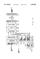
- FIG. 4 is a diagram showing one embodiment of an OFDM transmitting apparatus according to this invention.
- FIG. 5 is a diagram showing one embodiment of an OFDM receiving apparatus according to this invention.
- FIG. 6 is a diagram showing one embodiment of a first AFC circuit 310 in FIG. 5;
- FIG. 7 is a diagram showing an OFDM modulation wave to which a guard interval is added
- FIG. 8A is a diagram showing input I data of an OFDM modulation wave to be input the first AFC circuit 310;
- FIG. 8B is a diagram showing delayed I data of an OFDM modulation wave to be input the first AFC circuit 310;
- FIG. 8C is a diagram showing a correlation coefficient SII to be output from a correlation calculator in FIG. 6;
- FIG. 9 is a diagram for explaining the operation of a RAM 316 in FIG. 5;
- FIG. 10 is a diagram showing one embodiment of a correlator 318 in FIG. 5;
- FIG. 11 is a diagram for explaining the operation of the correlator 318 in FIG. 5;
- FIG. 12 is a diagram for also explaining the operation of the correlator 318.
- FIG. 13 is a diagram showing another embodiment of the correlator 318 in FIG. 5;
- FIG. 14 is a diagram showing the structure of an offset detector 320
- FIG. 15 is a diagram showing another embodiment of an OFDM transmitting apparatus according to this invention.
- FIG. 16 is a diagram showing another embodiment of an OFDM receiving apparatus according to this invention.
- FIG. 17 is a diagram showing a further embodiment of an OFDM transmitting apparatus according to this invention.
- FIG. 18 is a diagram showing a further embodiment of an OFDM receiving apparatus according to this invention.
- FIGS. 1 and 2 are diagrams presented for explaining the techniques on which this invention is premised.
- FIG. 1 shows the structure of one frame in the OFDM transmission format
- FIG. 2 shows an example of a frequency reference carrier.
- One frame in FIG. 1 consists of, for example, 150 OFDM symbols each having 869 carriers, for example.
- the first OFDM symbol from the head of the frame is a null symbol for the synchronization of reception
- the second OFDM symbol is a sine sweep symbol
- the third OFDM symbol is a frequency reference symbol
- the fourth and subsequent OFDM symbols are information symbols.
- the null symbol and sine sweep symbol are used for timing synchronization and equalization reference signals in a receiver.
- the frequency reference symbol is used to detect the frequency offset in a receiver.
- FIG. 2 exemplifies the structure of the frequency reference symbol.
- This structure of the frequency reference symbol has a carrier present every 16-carrier position among 869 carrier positions, and has no carriers present at the other carrier positions.
- the decoder detects the carrier frequency offset based on an offset of the position of decoded data of the frequency reference symbol. It is therefore possible to control the carrier frequency offset with the resolution of ⁇ 7 carrier position intervals.
- This OFDM transmission system however has the following shortcomings. First, since a frequency reference symbol having carriers located every other 16 carrier positions is used, the frequency-offset acquisition range is limited to the interval of ⁇ 7 carrier positions.
- the carriers are arranged equidistant, they are susceptible to multipath interference.
- a multipath an amplitude drop occurs at a specific frequency by the interference between a direct wave and an echo.
- amplitude attenuation occurs at periodic frequency intervals.
- this invention provides an OFDM transmission system which will be discussed below.
- FIG. 3 shows the spectrum of a frequency reference symbol in an OFDM transmission system according to one embodiment of this invention.
- one OFDM symbol consists of N carrier positions among which n carrier positions are effective carrier positions. Of the effective carrier positions, middle m carrier positions are frequency reference carrier positions for frequency references.
- carries are arranged in a pattern of an M sequence, for example, by using this M sequence as a PN (Pseudo Noise) code. More specifically, no carries are present when the code is "0" and carries are present when the code is "1.”
- PN Pulseudo Noise
- random QPSK data is transmitted using those carriers. This is because this approach is effective in making the amplitudes of the individual carriers constant and making the individual carriers to have random phases.
- the constant amplitudes are ensured to allow the receiver to acquire the amplitudes of the frequency reference symbols to detect the carrier arrangement pattern.
- the phases of the individual carries are set at random here because if the carriers are in phase, the modulation waveform has a high peak which makes signal transmission difficult.
- the randomness of the phases of the individual carriers means to prevent the carriers from being in phase with one another, and the transmission of QPSK data is effective in accomplishing the random phases.
- the data transmission efficiency can be improved even when independent data having a significance is used as the QPSK data.
- the presence/absence of carriers on the frequency axis is determined by a PN code, a QPSK symbol is assigned to an existing carrier and IFFT (Inverse Fast Fourier Transform) is performed on signals at N points, so that the time waveform of the frequency reference symbols is formed.
- IFFT Inverse Fast Fourier Transform
- FIG. 3 shows a frequency reference symbol having carriers arranged in a PN sequence pattern, it is not limited to this particular type but a frequency reference symbol which has carriers arranged in a predetermined non-equidistant pattern may be used as well.
- the middle m carrier positions are used for reference carriers, the other carrier positions or all the carrier positions may be used to arrange the reference carriers.
- another PSK symbol may be used as the transmission symbol.
- FIG. 4 shows one embodiment of an OFDM transmitting apparatus according to this invention.
- main data is encoded by an error correcting/coding unit 201 whose coded output is interleaved to reduce the influence of an burst error by an interleaver 202.
- the output of this interleaver 202 is supplied to a mapping circuit 203.
- the mapping circuit 203 converts input data to complex data which represents, for example, a QAM symbol and sends it to a multiplexer 207 as information symbol data.
- a null symbol generator 204 generates 0 data for generating a null symbol and supplies it to the multiplexer 207.
- a sine sweep generator 205 generates sine data for generating a sine sweep signal, and sends it to the multiplexer 207.
- a frequency reference symbol generator 206 generates data for the reference symbols that have already been discussed with reference to FIG. 3, and sends the data to the multiplexer 207.
- the multiplexer 207 multiplexes the individual inputs in the order of the null symbol, sine sweep symbol, frequency reference symbol and information symbol to produce a transmission frame.
- the output of the multiplexer 207 is supplied to an IFFT circuit 208, which performs IFFT to generate the real component and imaginary component of the base-band OFDM modulation wave.
- the output of the IFFT circuit 208 is supplied to a guard interval adding circuit 209, which copies the rear portion of a single OFDM symbol to the front of the symbol as a guard interval in order to reduce the influence of multipath interference.
- the output of this adding circuit 209 is subjected to quadrature modulation by a carrier with a predetermined frequency in an quadrature modulator 210.
- the modulated output is converted to an analog signal by a D/A (Digital to Analog) converter 211.
- the output of the D/A converter 211 is frequency-converted to an RF signal by a frequency converter 212 before transmission.
- a clock is input to a timing circuit 213, which produces drive clocks and timing pulses to the individual circuits.
- FIG. 5 shows one embodiment of an OFDM receiving apparatus according to this invention.
- a frequency difference of OFDM modulation wave between a transmitter and a receiver is caused by an analog local oscillator in a frequency converter 301.
- the frequency difference above is eliminated by controlling of a detection frequency at a quadrature demodulator 303.
- the converted signal is converted by an A/D (Analog to Digital) converter 302 to a digital signal which is in turn input to the quadrature demodulator 303.
- the quadrature demodulator 303 performs quadrature detection using carrier from a numerical control oscillator (NCO) 312 and outputs a base-band OFDM modulation wave.
- NCO numerical control oscillator
- the output (I signal) along the in-phase detection axis and the output (Q signal) of the quadrature detection axis of the quadrature demodulator 303 are the real component and imaginary component of the OFDM modulation wave, respectively.
- the I signal and Q signal are input to an FFT circuit 304.
- the FFT circuit 304 performs FFT on the received OFDM modulation wave.
- the output of the FFT circuit 304 is complex data representing the amplitude and phase of each carrier and multipath-originated amplitude and phase offsets are corrected by an equalizer 305.
- An information symbol is separated from the output of the equalizer 305 by a demultiplexer 306 and the resultant data is supplied to a demapping circuit 307.
- the demapping circuit 307 decodes the received complex symbol data.
- the output of the demapping circuit 307 is deinterleaved by a deinterleaver 308 to reduce the influence caused by a burst error, and the deinterleaved data is decoded by an error correcting/ decoding unit 309.
- the decoded data is output as main data.
- the output of the quadrature demodulator 303 is also supplied to a first AFC (Automatic Frequency Control) circuit 310.
- the AFC circuit 310 detects the carrier (LO carrier) frequency offset from the output of the quadrature demodulator 303 and generates a signal for compensating for this frequency offset.
- the output of the first AFC circuit 310 is supplied via an adder 311 to the NCO 312 so that the frequency of the LO carrier are controlled.
- the output of the FFT circuit 304 is also input to a second AFC circuit 313.
- the second AFC circuit 313 initiates its operation after the first AFC circuit 310 finishes the frequency acquisition. After the completion of frequency acquisition by the first AFC circuit 310, there remains a frequency offset of an integer multiple of the OFDM carrier spacing. When a frequency offset of 10 fs, for example, is present at this time, the output of the FFT circuit 304 is shifted by 10 samples.
- the second AFC circuit 313 detects an offset in received data to detect a carrier frequency offset in the units of fs.
- the I data and Q data of the received symbol from the FFT circuit 304 are input to an amplitude detector 314 which detects the amplitude of the symbol.
- a threshold determining circuit 315 compares the output of the amplitude detector 314 with a predetermined threshold value, and outputs "0" when the symbol amplitude is smaller than the threshold value and outputs "1" when the former is equal to or greater than the latter. This is because that the frequency reference symbol has no carrier when the code is "0" and has a carrier when the code is "1.”
- the output of the threshold determining circuit 315 is supplied to a RAM 316 where the result of the determination of the frequency reference symbol (no carriers when it is “0" and the presence of a carrier when it is “1") is written in response to a write control signal from a control circuit 321.
- the carrier arrangement pattern of the received frequency reference symbol is output to a correlator 318 from the RAM 316 in response to a read control signal from the control circuit 312.
- the correlator 318 is controlled by a control signal from the control circuit 321 to acquire the correlation between the reception pattern and transmission pattern.
- the output of the correlator 318 indicates a peak when the reception pattern matches with the transmission pattern.
- a threshold determining circuit 319 When the output of the correlator 318 is equal to or greater than a predetermined threshold value, a threshold determining circuit 319 outputs "1" and detects the timing which indicates the peak correlation output.
- An offset detector 320 detects the difference between the reception pattern and transmission pattern from the output of the threshold determining circuit 319 and the signal from the control circuit 321, and generates a signal to compensate for the frequency offset of reproduction carriers in the units of fs.
- the output of the offset detector 320 is supplied to the adder 311 as the output of the second AFC circuit 313.
- the output of the first AFC circuit 310 is also supplied to the adder 311 from which the addition result is output to the NCO 312. Accordingly, the oscillation frequency of the NCO 312 is controlled to accomplish the carrier frequency synchronization.
- the output of the quadrature demodulator 303 is supplied to a timing synchronization circuit 322 which generates clocks and timing pulses to the individual circuits.
- FIG. 6 exemplifies the specific structure of the first AFC circuit 310.
- FIG. 7 shows the I data of a base-band OFDM modulation wave.
- the OFDM modulation wave has a waveform close to that of random noise.
- the OFDM modulation wave is added with a guard interval by copying a part of the second half of an effective symbol to the front of that symbol.
- the input I data and input Q data of the base-band OFDM modulation wave which are outputs of the quadrature demodulator 303, are respective input to shift registers 401 and 402.
- the shift registers 401 and 402 respectively delay the I data and Q data by the effective symbol length of the OFDM symbol.
- the input I data and the delayed I data output from the shift register 401 are supplied to a correlation calculator 403.
- the two input signals are multiplied by a multiplier 405.
- the output of the multiplier 405 is input to a shift register 406 to be delayed by the guard interval of the OFDM symbol.
- the difference between the output of the multiplier 405 and the output of the shift register 406 is obtained by a subtracter 407.
- the output of this subtracter 407 is accumulated by an adder 408 and a latch circuit 409. As a result, the average movement of the result of multiplying in the guard interval is acquired.
- the above-described correlation calculator 403 detects a correlation coefficient (SII) indicating the correlation between the input I data and the delayed I data.
- SII correlation coefficient
- the input I data and the delayed Q data output from the shift register 402 are supplied to a correlation calculator 404, which detects a correlation coefficient (SIQ) indicating the correlation between the input I data and the delayed Q data in a similar manner.
- the correlation calculator 404 has a multiplier 410, a shift register 411, a subtracter 412, an adder 413 and a latch circuit 414.
- the outputs of the correlation calculators 403 and 404 are input to an arc tangent (tan -1 ) calculator 415 which detects tan -1 (SIQ/SII).
- the output of the tan -1 calculator 415 is input to a latch circuit 416, which latches a value at the boundary between symbols by symbol timing and outputs the resultant signal as a carrier frequency offset signal.
- FIG. 7 shows the I data of a base-band OFDM modulation wave.
- the OFDM modulation wave has a waveform close to that of random noise.
- the OFDM modulation wave is added with a guard interval by copying a part of the second half of an effective symbol to the front of that symbol.
- FIGS. 8A through 8C present timing charts illustrating the operation of the first AFC circuit 310.
- FIG. 8A shows the input I data
- FIG. 8B shows the output (delayed I data) of the shift register 401
- FIG. 8C shows the correlation coefficient SII from the correlation calculator 403.
- An OFDM modulation wave has guard intervals G1, G2 and so forth affixed to the heads of individual effective symbols S1, S2 and so forth.
- the guard intervals G1, G2 and so forth are obtained by copying tail periods Gi', G2' and so forth of the effective symbols S1, S2 and so forth (see FIG. 7).
- the timings of the guard intervals G1, G2 and so forth of the delayed I 5 data respectively coincide with the tail periods G1', G2' and so forth of the input I data, as shown in FIGS. 8A and 8B.
- a signal in the guard interval is the copy of a signal in the associated tail period, the correlation between the input I data and the delayed I data is high in this period. In the other periods, however, the correlation between the input I data and the delayed I data is low because the I data is a noise-like signal as shown in FIG. 7. Accordingly, the correlation coefficient SII gradually increases from the start timings of the tail periods G1', G2' and so forth and becomes a peak at the end timings of the tail periods (the boundary between OFDM symbols) as shown in FIG. 8C.
- the correlation coefficient SIQ between the input I data and the delayed Q data takes a value in the vicinity of "0".
- FIG. 8C shows the correlation coefficient SII when the carrier synchronization is achieved
- the correlation coefficient does not become high in the tail period when the carrier synchronization is not achieved.
- the frequency offset ⁇ f of reproduction carriers is fs/4 (fs: the frequency difference between adjoining carriers)
- the phase is shifted 90 degrees in the effective symbol period so that the phase of the signal in the period G' leads the phase of the signal in the period G by 90 degrees.
- the correlation coefficient SII becomes a value close to "0" and the correlation coefficient SIQ has a negative peak at the end timing of the tail period.
- the correlation coefficients SII and SIQ at the guard timing are functions of the frequency offset ⁇ f of reproduction carriers and the arc tangent of SIQ/SII becomes a signal which zero-crosses at the positions of integer multiples of fs.
- the frequency offset signal can therefore be acquired by supplying tan -1 (SIQ/SII), the output of the tan -1 calculator 415, to the latch circuit 416 and latching a value at the boundary between symbols by symbol timing (guard timing).
- the I data and Q data output from the FFT circuit 304 are input to the amplitude detector 314 which detects the amplitude of the symbol.
- the threshold determining circuit 315 compares the output of the amplitude detector 314 with a predetermined threshold value, and outputs "0" when the symbol amplitude is smaller than the threshold value and outputs "1" when the former is equal to or greater than the latter.
- the output of the threshold determining circuit 315 is supplied to the RAM 316 where the result of the determination of the frequency reference symbol (no carriers when it is "0" and the presence of a carrier when it is "1") is written in response to the write control signal from the control circuit 321.
- the carrier arrangement pattern of the received frequency reference symbol is output to the correlator 318 from the RAM 316 in response to the read control signal from the control circuit 312.
- the correlator 318 is controlled by the control signal from the control circuit 321 to acquire the correlation between the reception pattern and transmission pattern.
- the output of the correlator 318 indicates a peak when the reception pattern coincides with the transmission patter.
- the threshold determining circuit 319 outputs "1" and detects the timing which indicates the peak correlation output.
- the offset detector 320 detects the difference between the reception pattern and transmission pattern from the output of the threshold determining circuit 319 and the signal from the control circuit 321, and generates a signal to compensate for the carrier frequency offset in the units of fs.
- the output of the offset detector 320 is supplied to the adder 311 as the output of the second AFC circuit 313.
- FIG. 9 is a diagram for explaining the writing operation and reading operation to the RAM 316.
- the middle m samples in the received reference data sequence and several tens of samples around the m samples are written in the RAM 316. This writing is determined by the expected frequency acquisition range, which is set to ⁇ 50 fs in the example of FIG. 9.
- consecutive m data are read from the RAM 316 and are subjected to the computation of the correlation with a reference PN sequence by the correlator 318. This calculation is repeated while offsetting the reading position as shown in FIG. 9.
- FIG. 10 shows the specific structure of the correlator 318 (FIG. 5).
- the reference data received from the RAM 316 is supplied to a determining circuit 601 which also receives reference data sent from a reference data generator 317.
- the determining circuit 601 outputs "1" when two input data match with each other and outputs "-1" when both do not match with each other.
- the output of the determining circuit 601 is supplied to an adder 602.
- the adder 602 and a latch circuit 603 add the output of the determining circuit 601 m times, and the addition result is output via a latch circuit 604.
- a correlation calculation start timing signal is supplied to the clear terminal of the latch circuit 603 from the control circuit 321 to clear the output of the latch circuit 603 to "0" when correlation calculation starts.
- a correlation calculation end timing signal is supplied to the clock terminal of the latch circuit 604 from the control circuit 321 so that the output of the latch circuit 603 is latched in the latch circuit 604 when m pieces of data are added.
- the above computation is repeated while shifting the reading position in the RAM 316 to detect the correction between the received reference data sequence and the transmitted reference data sequence.
- FIG. 11 illustrates the output of the correlator 318 when the reference data is an M sequence with a length of 1023 and the carrier frequency offset is "0."
- the horizontal scale in FIG. 11 represents the amount of the offset of the reading position in the RAM 316. Because the M sequence has a high self-correlation, the correlation output shows a high peak when the reception pattern matches with the transmission pattern (the offset amount of 50) as shown in FIG. 11. As the length m of the sequence of reference data increases, the correlation peak becomes higher and the system is less influenced by noise, multipath interference or the like. Thus, the length m of the sequence of reference data is determined by the conditions or the like of the transmission channel in use.
- FIG. 12 shows the output of the correlator 318 when the carrier frequency offset is ⁇ 10 fs.
- the output of the FFT circuit 304 is shifted by +10 samples along the frequency axis.
- the timing at which the correlation output shows a peak in FIG. 12 is shifted by +10 samples from the timing in FIG. 11. Therefore, an frequency offset in the units of fs can be known by detecting the offset of the timing at which the correlation output shows a peak. This offset is detected by the offset detector 320.
- FIG. 13 shows another embodiment of the correlator 318.
- the correlator in FIG. 13 differs from the one in FIG. 10 in that the determining circuit 601 in FIG. 10 is replaced with an exclusive NOR (EX•NOR) gate 901.
- the other structure is the same as the correlator in FIG. 10.
- the EX•NOR gate 901 outputs "1" when two input data (received reference data and transmitted reference data) match with each other, and outputs "0" when there is no match. From this output of the EX•NOR gate 901, the correlation between the received reference data sequence and transmitted reference data sequence can be detected in the same manner as done in the circuit in FIG. 10.
- FIG. 14 exemplifies the specific structure of the offset detector 320 shown in FIG. 5.
- the offset amount read from the RAM 316 is supplied to a latch circuit 1001 from the control circuit 321.
- the output of the threshold determining circuit 319 is supplied to the clock terminal of the latch circuit 1001 to hold the offset amount read from the RAM 316 when the correlation output becomes equal to or greater than a predetermined level.
- the output of the latch circuit 1001 is supplied to an error signal generator 1002 which generates a signal for compensation of the frequency offset in the units of fs.
- the output of the error signal generator 1002 is sent out as a frequency offset signal via a latch circuit 1003.
- An offset signal detection timing signal is connected via an AND gate 1005 to the clock terminal of the latch circuit 1003 from the control circuit 321, so that the offset signal is latched at a predetermined timing.
- a reset signal form the control circuit 321 and the output of the threshold determining circuit 319 are respectively input to the reset terminal and set terminal of an RS flip-flop circuit 1004 whose output is supplied to the AND gate 1005.
- the output of the RS flip-flop circuit 1004 is reset to "0" at the head of a transmission frame and is set to "1" when the correlation output becomes equal to or greater than a predetermined level.
- the output of the RS flip-flop circuit 1004 stays “0” so that the output of the AND gate 1005 becomes “0.”
- offset data is not latched in the latch circuit 1003.
- a power-on reset signal is supplied to the clear terminal of the latch circuit 1003 so that the frequency offset data is cleared to "0" until the first correlation peak is detected.
- each carrier carries a QPSK symbol in the frequency reference symbol shown in FIG. 3, independent data other than the main data can be transferred using this QPSK symbol.
- FIG. 15 shows one embodiment of an OFDM transmitting apparatus which transfers independent data by a frequency reference symbol.
- independent data is coded by a error correcting/coding unit 1101, and the corrected/coded signal is input to a reference symbol generator 1102.
- An output of the reference symbol generator 1102 is multiplexed and transferred by the multiplexer 207.
- FIG. 16 shows one embodiment of an OFDM receiving apparatus corresponding to the OFDM transmitting apparatus shown in FIG. 15.
- a demodulated frequency reference symbol is separated by a demultiplexer 306 and is input to a reference symbol decoder 1201.
- the reference symbol decoder 1201 decodes, for example, a QPSK symbol in the frequency reference symbol.
- the output of the reference symbol decoder 1201 is decoded by an error correcting/decoding unit 1202 to be output as independent data.
- a plurality of carrier arrangement patterns may be prepared so that independent data other than information symbols can be transferred in association with the carrier arrangement patterns.
- the carrier arrangement patterns themselves represent the contents of data.
- FIG. 17 shows one embodiment of an OFDM transmitting apparatus which transfers operation parameters as independent data by the frequency reference symbol that has a plurality of carrier arrangement patterns. More specifically, FIG. 17 exemplifies an apparatus which transfers operation parameter information of the error correcting section, interleaving section and mapping section as independent data.
- an error correcting/coding unit 1301, an interleaver 1302 and a mapping circuit 1303 are designed to change their operation parameters based on control data.
- the parameters of the individual sections include the redundancy of an error correcting code, the depth of interleaving and the modulation scheme for the individual carriers. By altering those parameters, the system can be optimized flexibly in accordance with the contents of main data and the transfer conditions.
- the control data is encoded by a control data coder 1304 and is then supplied to a reference symbol generator 1305.
- the reference symbol generator 1305 generates a frequency reference symbol of a predetermined pattern from among a plurality of patterns in accordance with input data.
- the output of the reference symbol generator 1305 is multiplexed by a multiplexer 207 before transmission.
- FIG. 18 exemplifies an OFDM receiving apparatus which is associated with the OFDM transmitting apparatus that transfer the operation parameters as independent data and which restores independent data.
- a reference data generator 1401 generates a plurality of PN sequences to be used on the transmission side.
- a correlator 1402 detects the correlations between a reception pattern and a plurality of patterns.
- a threshold determining circuit 1403 compares each input correlation value with a predetermined level, determines that a pattern whose correlation value becomes equal to or greater than a predetermined level is the transmitted pattern, and outputs a signal indicative of the carrier arrangement pattern of the frequency reference symbol to a control data decoder 1404.
- the control data decoder 1404 decodes parameter control data in accordance with the carrier arrangement pattern of the frequency reference symbol.
- the output of the control data decoder 1404 is supplied to a demapping circuit 1405, a deinterleaver 1406 and an error correcting/decoding unit 1407. Accordingly, the parameters of the individual sections can be altered in accordance with the parameters on the transmission side.
- this invention can widen the frequency acquisition range and can improve the resistance to multipath interference. This invention can also improve the data transfer efficiency.
Abstract
Description
Claims (15)
Applications Claiming Priority (2)
| Application Number | Priority Date | Filing Date | Title |
|---|---|---|---|
| JP3704995A JP3130752B2 (en) | 1995-02-24 | 1995-02-24 | OFDM transmission receiving method and transmitting / receiving apparatus |
| JP7-037049 | 1995-02-24 |
Publications (1)
| Publication Number | Publication Date |
|---|---|
| US5694389A true US5694389A (en) | 1997-12-02 |
Family
ID=12486735
Family Applications (1)
| Application Number | Title | Priority Date | Filing Date |
|---|---|---|---|
| US08/605,742 Expired - Fee Related US5694389A (en) | 1995-02-24 | 1996-02-22 | OFDM transmission/reception system and transmitting/receiving apparatus |
Country Status (6)
| Country | Link |
|---|---|
| US (1) | US5694389A (en) |
| EP (1) | EP0729250B1 (en) |
| JP (1) | JP3130752B2 (en) |
| KR (1) | KR960032953A (en) |
| CA (1) | CA2170094C (en) |
| DE (1) | DE69627568T2 (en) |
Cited By (151)
| Publication number | Priority date | Publication date | Assignee | Title |
|---|---|---|---|---|
| WO1999003227A2 (en) * | 1997-06-26 | 1999-01-21 | Nokia Telecommunications Oy | Method for eliminating interference in an ofdm radio receiver |
| US5923666A (en) * | 1995-10-24 | 1999-07-13 | Nds Limited | Decoding carriers encoded using orthogonal frequency division multiplexing |
| US5963851A (en) * | 1997-04-07 | 1999-10-05 | Motorola, Inc. | Automatic frequency control system using multiple threshold levels and method of using same |
| US5995168A (en) * | 1996-01-31 | 1999-11-30 | Nec Corporation | Digital video receiver |
| US6005840A (en) * | 1997-04-01 | 1999-12-21 | Lucent Technologies Inc. | Complementary encoding and modulation system for use in an orthogonal frequency division multiplexing transmitter system and method thereof |
| US6035003A (en) * | 1996-11-29 | 2000-03-07 | Daewoo Electronics Co., Ltd. | Apparatus for correcting frequency offset in OFDM receiving system |
| US6058145A (en) * | 1996-12-24 | 2000-05-02 | Sharp Kabushiki Kaisha | Method of demodulating a multi-frequency quadrature modulated signal |
| US6074086A (en) * | 1999-04-26 | 2000-06-13 | Intellon Corporation | Synchronization of OFDM signals with improved windowing |
| US6108353A (en) * | 1997-01-20 | 2000-08-22 | Sony Corporation | Demodulating apparatus |
| US6111919A (en) * | 1999-01-20 | 2000-08-29 | Intellon Corporation | Synchronization of OFDM signals |
| US6115354A (en) * | 1994-07-20 | 2000-09-05 | Timlar Konle | Multiple carrier transmission in common-wave networks |
| US6160821A (en) * | 1997-11-05 | 2000-12-12 | Sony International (Europe) Gmbh | Synchronization of digital communication systems |
| KR20010001707A (en) * | 1999-06-08 | 2001-01-05 | 윤종용 | Apparatus for acquiering coarse synchronization and method thereof in orthogonal frequency division multiplexing/code division multiple access system |
| US6191649B1 (en) * | 1998-07-03 | 2001-02-20 | Kabushiki Kaisha Toshiba | Quadrature demodulator and method for quadrature demodulation |
| US6208695B1 (en) | 1996-02-02 | 2001-03-27 | Deutsche Thomson-Brandt Gmbh | Method for reception of multicarrier signals and related apparatus |
| WO2001028150A2 (en) | 1999-10-12 | 2001-04-19 | Atheros Communications, Inc. | Method and apparatus for eliminating the effects of frequency offsets in a digital communication system |
| WO2001041313A1 (en) * | 1999-12-06 | 2001-06-07 | Intellon Corporation | Forward error correction with channel adaptation |
| US6269132B1 (en) | 1999-04-26 | 2001-07-31 | Intellon Corporation | Windowing function for maintaining orthogonality of channels in the reception of OFDM symbols |
| US6275551B1 (en) * | 1997-07-31 | 2001-08-14 | Sony Corporation | Apparatus for receiving digital information signals |
| US6278685B1 (en) | 1999-08-19 | 2001-08-21 | Intellon Corporation | Robust transmission mode |
| US6278865B1 (en) * | 1996-11-27 | 2001-08-21 | Nokia Telecommunications Oy | Receiver and method for measuring the frequency difference between a turning frequency and a transmission frequency |
| WO2001063803A1 (en) * | 2000-02-22 | 2001-08-30 | Xros, Inc. | Simple, high-speed optical signal pattern and protocol detection |
| US6289000B1 (en) | 2000-05-19 | 2001-09-11 | Intellon Corporation | Frame control encoder/decoder for robust OFDM frame transmissions |
| US6301221B1 (en) * | 1997-09-10 | 2001-10-09 | Hewlett-Packard Company | Methods and apparatus for encoding data |
| KR100312318B1 (en) * | 1998-12-01 | 2001-11-05 | 윤종용 | Frequency synchronizing device for ofdm/cdma system |
| US6314083B1 (en) * | 1997-04-04 | 2001-11-06 | Nippon Columbia Co., Ltd. | Frequency control device and method for frequency synchronization with multiplex signal by OFDM, receiving device, and communication device |
| US6359938B1 (en) * | 1996-10-31 | 2002-03-19 | Discovision Associates | Single chip VLSI implementation of a digital receiver employing orthogonal frequency division multiplexing |
| US20020034214A1 (en) * | 2000-04-13 | 2002-03-21 | Takahiro Okada | OFDM receiving device and OFDM receiving method |
| US6381251B1 (en) | 1997-06-12 | 2002-04-30 | Hitachi Denshi Kabushiki Kaisha | Data transmission apparatus and receiving apparatus using orthogonal frequency division multiplex modulation system |
| WO2002054755A2 (en) * | 2001-01-04 | 2002-07-11 | Telisar Corporation | System for nondisruptively embedding ofdm data into a composite video signal |
| US20020094050A1 (en) * | 2000-03-15 | 2002-07-18 | Takashi Usui | Data modulation method, data modulation device and communication device |
| US6442129B1 (en) | 1999-12-06 | 2002-08-27 | Intellon Corporation | Enhanced channel estimation |
| US6459745B1 (en) * | 1999-09-23 | 2002-10-01 | The United States Of America As Represented By The Secretary Of The Navy | Frequency/timing recovery circuit for orthogonal frequency division multiplexed signals |
| US20020150181A1 (en) * | 2001-02-28 | 2002-10-17 | Zulfiquar Sayeed | Method and apparatus for recovering timing information in orthogonal frequency division multiplexing (OFDM) systems |
| US6505037B1 (en) | 1999-06-29 | 2003-01-07 | Sharp Laboratories Of America, Inc. | Data unit detection including antenna diversity |
| US20030016768A1 (en) * | 2001-07-19 | 2003-01-23 | Gang Huang | System and method for recognizing zero-amplitude symbols in a QAM signal and digital receiver incorporating the same |
| US6539063B1 (en) | 1999-02-18 | 2003-03-25 | Ibiquity Digital Corporation | System and method for recovering symbol timing offset and carrier frequency error in an OFDM digital audio broadcast system |
| US20030071925A1 (en) * | 2001-10-02 | 2003-04-17 | Ippei Kanno | Receiving apparatus |
| US6560298B1 (en) * | 1999-05-25 | 2003-05-06 | Motorola, Inc. | Method and apparatus for concurrent synchronization and improved automatic frequency control in a communication device |
| US6563896B1 (en) * | 1998-08-04 | 2003-05-13 | Sony Corporation | Digital broadcast receiver and receiving method |
| US20030090994A1 (en) * | 2001-11-13 | 2003-05-15 | Nec Corporation | Guard interval length control method in OFDM system and OFDM transmitting and receiving apparatuses |
| US20030117940A1 (en) * | 2001-12-26 | 2003-06-26 | Joseph Smallcomb | Method and apparatus for timing recovery in an OFDM system |
| US6597826B1 (en) | 1999-11-02 | 2003-07-22 | Xros, Inc. | Optical cross-connect switching system with bridging, test access and redundancy |
| US20030137928A1 (en) * | 1999-11-10 | 2003-07-24 | Kroeger Brian William | Method and apparatus for transmission and reception of FM in-band on-channel digital audio broadcasting |
| US6606357B1 (en) | 1999-09-10 | 2003-08-12 | Harris Corporation | Carrier injecting waveform-based modulation scheme for reducing satellite transponder power requirements and earth terminal antenna size |
| US6606296B1 (en) * | 1997-01-16 | 2003-08-12 | Nokia Corporation | Data transmission method and radio system |
| US6611493B1 (en) * | 1998-01-27 | 2003-08-26 | Hitachi Denshi Kabushiki Kaisha | Communication, transmission and receiving method and apparatus using orthogonal frequency division multiplexing modulation system |
| US6618352B1 (en) * | 1998-05-26 | 2003-09-09 | Matsushita Electric Industrial Co., Ltd. | Modulator, demodulator, and transmission system for use in OFDM transmission |
| US6628735B1 (en) | 1999-12-22 | 2003-09-30 | Thomson Licensing S.A. | Correction of a sampling frequency offset in an orthogonal frequency division multiplexing system |
| US20030185147A1 (en) * | 2002-03-26 | 2003-10-02 | Kabushiki Kaisha Toshiba | OFDM receiving apparatus and method of demodulation in OFDM receving apparatus |
| US20030198179A1 (en) * | 2002-04-22 | 2003-10-23 | Samsung Electronics Co., Ltd. | Ranging method for mobile communication system based on orthogonal frequency division multiple access scheme |
| US20030210646A1 (en) * | 2002-05-10 | 2003-11-13 | Kddi Corporation | Frequency error correction device and OFDM receiver with the device |
| US6650803B1 (en) | 1999-11-02 | 2003-11-18 | Xros, Inc. | Method and apparatus for optical to electrical to optical conversion in an optical cross-connect switch |
| US6687315B2 (en) | 1997-02-18 | 2004-02-03 | Discovision Associate | Single chip VLSI implementation of a digital receiver employing orthogonal frequency division multiplexing |
| US6687309B1 (en) * | 2000-09-29 | 2004-02-03 | Agilent Technologies, Inc. | System for estimating carrier frequencies of quadrature amplitude modulated signals having high symbol rates |
| KR100418975B1 (en) * | 2001-06-12 | 2004-02-14 | 전자부품연구원 | A synchronization apparatus and method of coarse frequency offset in digital audio broadcasting system |
| US6700866B1 (en) | 1999-06-23 | 2004-03-02 | At&T Wireless Services, Inc. | Methods and apparatus for use in obtaining frequency synchronization in an OFDM communication system |
| US6704374B1 (en) | 2000-02-16 | 2004-03-09 | Thomson Licensing S.A. | Local oscillator frequency correction in an orthogonal frequency division multiplexing system |
| US6711221B1 (en) | 2000-02-16 | 2004-03-23 | Thomson Licensing S.A. | Sampling offset correction in an orthogonal frequency division multiplexing system |
| US6731594B1 (en) * | 1997-09-04 | 2004-05-04 | Sony International (Europe) Gmbh | Transmission system for OFDM-signals with optimized synchronisation |
| US6744828B1 (en) * | 1999-05-27 | 2004-06-01 | Pioneer Corporation | Receiving apparatus |
| US6747948B1 (en) * | 1999-08-11 | 2004-06-08 | Lucent Technologies Inc. | Interleaver scheme in an OFDM system with multiple-stream data sources |
| US6751272B1 (en) * | 1998-02-11 | 2004-06-15 | 3Com Corporation | Dynamic adjustment to preserve signal-to-noise ratio in a quadrature detector system |
| US6762991B1 (en) * | 1999-03-19 | 2004-07-13 | Kabushiki Kaisha Kaisha | Signal generator and OFDM modulator synchronized to external device |
| US6768714B1 (en) | 1999-06-23 | 2004-07-27 | At&T Wireless Services, Inc. | Methods and apparatus for use in obtaining frequency synchronization in an OFDM communication system |
| KR100442350B1 (en) * | 2002-01-23 | 2004-07-30 | 엘지전자 주식회사 | Carrier frequency synchronization apparatus and method in orthogonal frequency-division multiplexing |
| US6792174B1 (en) | 1999-11-02 | 2004-09-14 | Nortel Networks Limited | Method and apparatus for signaling between an optical cross-connect switch and attached network equipment |
| US6804192B1 (en) | 1996-08-22 | 2004-10-12 | Tellabs Operations, Inc. | OFDM/DMT digital communications system including partial sequence symbol processing |
| US20040233836A1 (en) * | 2002-03-26 | 2004-11-25 | Atsushi Sumasu | Multi-carrier transmission apparatus and multi-carrier transmission method |
| US6859504B1 (en) | 1999-06-29 | 2005-02-22 | Sharp Laboratories Of America, Inc. | Rapid settling automatic gain control with minimal signal distortion |
| US6882765B1 (en) | 1999-11-02 | 2005-04-19 | Xros, Inc. | Connection protection between clients and optical cross-connect switches |
| US6907044B1 (en) | 2000-08-04 | 2005-06-14 | Intellon Corporation | Method and protocol to support contention-free intervals and QoS in a CSMA network |
| US20050129135A1 (en) * | 2003-12-15 | 2005-06-16 | Samsung Thales Co., Ltd. | Method and apparatus for compensating for residual frequency offset in an OFDM system |
| US6909723B1 (en) | 2000-08-04 | 2005-06-21 | Intellon Corporation | Segment bursting with priority pre-emption and reduced latency |
| US20050190848A1 (en) * | 2002-12-19 | 2005-09-01 | Hiroyuki Kiyanagii | OFDM transceiver apparatus |
| KR100493269B1 (en) * | 1998-06-05 | 2005-09-07 | 엘지전자 주식회사 | Digital TV automatic frequency control device |
| US20050213692A1 (en) * | 2003-07-22 | 2005-09-29 | Sergey Zhidkov | Impulse noise reduction to an MCM signal |
| US20050220001A1 (en) * | 2002-02-28 | 2005-10-06 | Henriksson Jukka A | Method and system for receiving a multi-carrier signal |
| US6985432B1 (en) * | 2000-01-28 | 2006-01-10 | Zion Hadad | OFDM communication channel |
| US6987770B1 (en) | 2000-08-04 | 2006-01-17 | Intellon Corporation | Frame forwarding in an adaptive network |
| US6993084B1 (en) * | 1998-04-14 | 2006-01-31 | Fraunhofer-Gesellschaft Zur Foerderung Der Angewandten Forschung E.V. | Coarse frequency synchronisation in multicarrier systems |
| US6992972B2 (en) | 1998-01-06 | 2006-01-31 | Agere Systems Inc. | Frequency division multiplexing system with selectable rate |
| US20060034166A1 (en) * | 1996-08-22 | 2006-02-16 | Marchok Daniel J | Apparatus and method for symbol alignment in a multi-point OFDM/DMT digital communications system |
| US20060039485A1 (en) * | 2002-04-30 | 2006-02-23 | Kenji Nowara | Pattern position measuring device, method, and program, and record medium on which the program is recorded |
| US7027464B1 (en) | 1999-07-30 | 2006-04-11 | Matsushita Electric Industrial Co., Ltd. | OFDM signal transmission scheme, and OFDM signal transmitter/receiver |
| US20060088007A1 (en) * | 2000-03-22 | 2006-04-27 | Ahmad Jalali | Multiplexing of real time services and non-real time services for OFDM systems |
| US7061997B1 (en) * | 1998-04-14 | 2006-06-13 | Fraunhofer-Gesellschaft Zur Foerderung Der Angewandten Forschung E.V. | Method and apparatus for fine frequency synchronization in multi-carrier demodulation systems |
| US7106689B1 (en) * | 1999-03-02 | 2006-09-12 | Matsushita Electric Industrial Co., Ltd. | OFDM transmission/reception apparatus |
| US7120847B2 (en) | 2002-06-26 | 2006-10-10 | Intellon Corporation | Powerline network flood control restriction |
| US7133456B2 (en) * | 1998-08-10 | 2006-11-07 | Kamilo Feher | Modulation and demodulation format selectable system |
| US20060280113A1 (en) * | 2005-06-10 | 2006-12-14 | Huo David D | Method and apparatus for dynamic allocation of pilot symbols |
| US7170849B1 (en) * | 2001-03-19 | 2007-01-30 | Cisco Systems Wireless Networking (Australia) Pty Limited | Interleaver, deinterleaver, interleaving method, and deinterleaving method for OFDM data |
| US20070097851A1 (en) * | 2003-05-20 | 2007-05-03 | Fumiyuki Adachi | Information recording device and information recording medthod |
| US7218691B1 (en) * | 2001-03-05 | 2007-05-15 | Marvell International Ltd. | Method and apparatus for estimation of orthogonal frequency division multiplexing symbol timing and carrier frequency offset |
| US20070127362A1 (en) * | 2005-12-02 | 2007-06-07 | Alcatel | Multi-carrier signals with selectable pilot pattern |
| US20070127583A1 (en) * | 2005-12-02 | 2007-06-07 | Alcatel | Digital Generator and Digital Receiver for FDM Signals |
| US20070162946A1 (en) * | 1995-02-06 | 2007-07-12 | Adc Telecommunications, Inc. | Round trip delay adjustment in multipoint-to-point communication using orthgonal frequency division multiplexing |
| US7281187B2 (en) | 2003-11-20 | 2007-10-09 | Intellon Corporation | Using error checking bits to communicated an address or other bits |
| US7298691B1 (en) | 2000-08-04 | 2007-11-20 | Intellon Corporation | Method and protocol to adapt each unique connection in a multi-node network to a maximum data rate |
| KR100781279B1 (en) * | 2006-01-16 | 2007-11-30 | 엘지전자 주식회사 | equalizer |
| US7324432B1 (en) * | 1999-07-05 | 2008-01-29 | Samsung Electronics Co., Ltd. | Apparatus of compensating for frequency offset using pilot symbol in an orthogonal frequency division multiplexing system |
| US7352770B1 (en) | 2000-08-04 | 2008-04-01 | Intellon Corporation | Media access control protocol with priority and contention-free intervals |
| US7356094B1 (en) * | 1999-03-10 | 2008-04-08 | Sony Corporation | Digital broadcast receiving apparatus |
| US20080144731A1 (en) * | 1996-08-22 | 2008-06-19 | Tellabs Operations, Inc. | Apparatus and method for clock synchronization in a multi-point OFDM/DMT digital communications system |
| US7469297B1 (en) | 2000-08-04 | 2008-12-23 | Intellon Corporation | Mechanism for using a quasi-addressed response to bind to a message requesting the response |
| US20090022245A1 (en) * | 2006-05-24 | 2009-01-22 | General Dynamics Advanced Information Systems | Low latency analog QAM coherent demodulation algorithm |
| US20090092197A1 (en) * | 2006-02-09 | 2009-04-09 | Takuya Okamoto | Ofdm demodulation device and method |
| US20090154333A1 (en) * | 2007-12-14 | 2009-06-18 | Sivaswamy Associates, Llc. | Orthogonal code division multiplex cck (ocdm-cck) method and apparatus for high data rate wireless lan |
| US7555054B2 (en) | 1998-08-10 | 2009-06-30 | Wi-Lan, Inc. | Methods and systems for transmission of multiple modulated signals over wireless networks |
| US7623542B2 (en) | 2002-10-21 | 2009-11-24 | Intellon Corporation | Contention-free access intervals on a CSMA network |
| US7636370B2 (en) | 2005-03-03 | 2009-12-22 | Intellon Corporation | Reserving time periods for communication on power line networks |
| US20100023836A1 (en) * | 2003-01-31 | 2010-01-28 | Panasonic Corporation | OFDM Signal Collision Position Detection Apparatus and OFDM Reception Apparatus |
| US7660327B2 (en) | 2004-02-03 | 2010-02-09 | Atheros Communications, Inc. | Temporary priority promotion for network communications in which access to a shared medium depends on a priority level |
| US20100091917A1 (en) * | 2007-05-30 | 2010-04-15 | Mitsubishi Electric Corporation | Digital broadcasting receiving apparatus |
| US7701999B1 (en) * | 2006-05-02 | 2010-04-20 | L3 Corrections Corporation | Non-coherent multiuser receiver and method for aiding carrier acquisition in a spread spectrum system |
| US7715425B2 (en) | 2004-02-26 | 2010-05-11 | Atheros Communications, Inc. | Channel adaptation synchronized to periodically varying channel |
| USRE41771E1 (en) | 1995-02-06 | 2010-09-28 | Adc Telecommunications, Inc. | System for multiple use subchannels |
| US7822059B2 (en) | 2005-07-27 | 2010-10-26 | Atheros Communications, Inc. | Managing contention-free time allocations in a network |
| US7826466B2 (en) | 2002-06-26 | 2010-11-02 | Atheros Communications, Inc. | Communication buffer scheme optimized for VoIP, QoS and data networking over a power line |
| US20110013708A1 (en) * | 2009-07-15 | 2011-01-20 | Cisco Technology, Inc. | Signal Sequence Detection Techniques for OFDM/OFDMA Systems |
| USRE42236E1 (en) | 1995-02-06 | 2011-03-22 | Adc Telecommunications, Inc. | Multiuse subcarriers in multipoint-to-point communication using orthogonal frequency division multiplexing |
| US7916801B2 (en) | 1998-05-29 | 2011-03-29 | Tellabs Operations, Inc. | Time-domain equalization for discrete multi-tone systems |
| US7957965B2 (en) | 2000-03-28 | 2011-06-07 | Tellabs Operations, Inc. | Communication system noise cancellation power signal calculation techniques |
| US20110255640A1 (en) * | 2008-09-26 | 2011-10-20 | Beijing Nufront Mobile Multimedia Tech. Co., Ltd. | Receiver, receiving device, and method for terrestrial mobile multimedia broadcasting |
| US8050288B2 (en) | 1998-06-30 | 2011-11-01 | Tellabs Operations, Inc. | Method and apparatus for interference suppression in orthogonal frequency division multiplexed (OFDM) wireless communication systems |
| US8090857B2 (en) | 2003-11-24 | 2012-01-03 | Qualcomm Atheros, Inc. | Medium access control layer that encapsulates data from a plurality of received data units into a plurality of independently transmittable blocks |
| US8102832B2 (en) | 2003-05-12 | 2012-01-24 | Qualcomm Incorporated | Fast frequency hopping with a code division multiplexed pilot in an OFDMA system |
| US8149703B2 (en) | 2002-06-26 | 2012-04-03 | Qualcomm Atheros, Inc. | Powerline network bridging congestion control |
| US8175190B2 (en) | 2005-07-27 | 2012-05-08 | Qualcomm Atheros, Inc. | Managing spectra of modulated signals in a communication network |
| US8238923B2 (en) | 2004-12-22 | 2012-08-07 | Qualcomm Incorporated | Method of using shared resources in a communication system |
| WO2012129320A1 (en) * | 2011-03-21 | 2012-09-27 | Adtran, Inc. | Correlation systems and methods with error compensation |
| USRE43703E1 (en) | 1997-09-04 | 2012-10-02 | Sony Deutschland Gmbh | Transmission system for OFDM-signals with optimized synchronization |
| US8493995B2 (en) | 2007-05-10 | 2013-07-23 | Qualcomm Incorporated | Managing distributed access to a shared medium |
| US8611283B2 (en) | 2004-01-28 | 2013-12-17 | Qualcomm Incorporated | Method and apparatus of using a single channel to provide acknowledgement and assignment messages |
| US8619922B1 (en) | 2002-02-04 | 2013-12-31 | Marvell International Ltd. | Method and apparatus for acquisition and tracking of orthogonal frequency division multiplexing symbol timing, carrier frequency offset and phase noise |
| US8638870B2 (en) | 2004-12-22 | 2014-01-28 | Qualcomm Incorporated | MC-CDMA multiplexing in an orthogonal uplink |
| US8660214B1 (en) * | 2012-12-09 | 2014-02-25 | Phuong Thu-Minh Huynh | Quadrature bandpass-sampling OFDM receiver |
| US8660013B2 (en) | 2010-04-12 | 2014-02-25 | Qualcomm Incorporated | Detecting delimiters for low-overhead communication in a network |
| US8724555B2 (en) | 2002-10-29 | 2014-05-13 | Qualcomm Incorporated | Uplink pilot and signaling transmission in wireless communication systems |
| US8892465B2 (en) | 2001-06-27 | 2014-11-18 | Skky Incorporated | Media delivery platform |
| US8891605B2 (en) | 2013-03-13 | 2014-11-18 | Qualcomm Incorporated | Variable line cycle adaptation for powerline communications |
| US9014250B2 (en) | 1998-04-03 | 2015-04-21 | Tellabs Operations, Inc. | Filter for impulse response shortening with additional spectral constraints for multicarrier transmission |
| US9197400B1 (en) * | 2012-05-21 | 2015-11-24 | Marvell International Ltd. | Method and apparatus for joint estimation of carrier frequency offset and sampling frequency offset |
| US9350587B1 (en) | 2012-11-30 | 2016-05-24 | Marvell International Ltd. | System and method for timing error estimation |
| US9480074B2 (en) | 2004-07-23 | 2016-10-25 | Qualcomm Incorporated | Enabling quick and easy demodulation |
| US9485128B2 (en) | 1999-11-09 | 2016-11-01 | Tq Delta, Llc | System and method for scrambling using a bit scrambler and a phase scrambler |
| US20170048022A1 (en) * | 2015-08-12 | 2017-02-16 | Fujitsu Limited | Transmission device, transmission system and transmission method |
| US20170048042A1 (en) * | 2009-02-08 | 2017-02-16 | Lg Electronics Inc. | Method for transmitting reference signal for terminal demodulation in radio mobile communication system, and apparatus for implementing the same |
| US9875440B1 (en) | 2010-10-26 | 2018-01-23 | Michael Lamport Commons | Intelligent control with hierarchical stacked neural networks |
| US10510000B1 (en) | 2010-10-26 | 2019-12-17 | Michael Lamport Commons | Intelligent control with hierarchical stacked neural networks |
| US10979257B2 (en) * | 2016-01-06 | 2021-04-13 | Apple Inc. | DC offset cancelation for wireless communications |
Families Citing this family (26)
| Publication number | Priority date | Publication date | Assignee | Title |
|---|---|---|---|---|
| US6991797B2 (en) | 1993-07-02 | 2006-01-31 | Statens Serum Institut | M. tuberculosis antigens |
| JP3421880B2 (en) * | 1994-10-05 | 2003-06-30 | ソニー株式会社 | Demodulator |
| JPH10145324A (en) * | 1996-11-13 | 1998-05-29 | Sony Corp | Discrimination device for digital audio broadcast |
| KR100245029B1 (en) * | 1997-02-14 | 2000-02-15 | 윤종용 | Receiving apparatus of ofdm method |
| KR100248652B1 (en) * | 1997-03-31 | 2000-03-15 | 전주범 | A circuit for transforming of phase signal in ofdm receiving system |
| US7037510B2 (en) | 1997-04-18 | 2006-05-02 | Statens Serum Institut | Hybrids of M. tuberculosis antigens |
| US6058101A (en) * | 1997-06-11 | 2000-05-02 | Industrial Technology Research Institute | Synchronization method and system for a digital receiver |
| IL133327A0 (en) * | 1997-06-20 | 2001-04-30 | Infineon Technologies Ag | Method for transferring data with a plurality of non-equidistant frequency bands |
| KR100263372B1 (en) * | 1997-11-29 | 2000-08-01 | 전주범 | Coarse frequency acquistion method and thereof appratus for orthogonal frequency division multiplexing systems |
| JPH11252038A (en) * | 1998-02-27 | 1999-09-17 | Sony Corp | Receiver for digital broadcasting |
| JPH11261526A (en) | 1998-03-10 | 1999-09-24 | Matsushita Electric Ind Co Ltd | Transmitter-receiver and method therefor |
| KR19990079604A (en) * | 1998-04-07 | 1999-11-05 | 구자홍 | Symbol deinterleaving device |
| JP3515690B2 (en) | 1998-06-02 | 2004-04-05 | 松下電器産業株式会社 | OFDMA signal transmission apparatus and method |
| KR100313860B1 (en) * | 1998-07-30 | 2001-12-12 | 윤종용 | Fine Frequency Reconstruction Device and Method in OFDM Transmission Method |
| GB9823145D0 (en) * | 1998-10-23 | 1998-12-16 | Philips Electronics Nv | Radio communication system |
| GB9823812D0 (en) * | 1998-10-30 | 1998-12-23 | Mitsubishi Electric Inf Tech | Multicarrier communications systems |
| DE19858106B4 (en) | 1998-12-16 | 2014-09-25 | Telefonaktiebolaget Lm Ericsson (Publ) | A receiver and method for preventing intersymbol interference in a high-speed transmission system |
| EP1021019A1 (en) | 1999-01-15 | 2000-07-19 | Sony International (Europe) GmbH | Quasi-differential modulation/demodulation method for multi-amplitude digital modulated signals and OFDM system |
| JP3715141B2 (en) * | 1999-07-13 | 2005-11-09 | 松下電器産業株式会社 | Communication terminal device |
| WO2003032543A1 (en) * | 2001-09-28 | 2003-04-17 | Fujitsu Limited | Automatic frequency control device for ofdm and method therefor |
| KR20040035291A (en) * | 2002-10-19 | 2004-04-29 | 삼성전자주식회사 | Multi-carrier transmission system having the pilot tone in frequence domain and a method inserting pilot tone thereof |
| US8064528B2 (en) | 2003-05-21 | 2011-11-22 | Regents Of The University Of Minnesota | Estimating frequency-offsets and multi-antenna channels in MIMO OFDM systems |
| US8401503B2 (en) | 2005-03-01 | 2013-03-19 | Qualcomm Incorporated | Dual-loop automatic frequency control for wireless communication |
| US8009775B2 (en) * | 2005-03-11 | 2011-08-30 | Qualcomm Incorporated | Automatic frequency control for a wireless communication system with multiple subcarriers |
| JP4699113B2 (en) * | 2005-07-05 | 2011-06-08 | パナソニック株式会社 | Multi-carrier communication apparatus and multi-carrier communication method |
| DE102007035807B4 (en) | 2007-06-01 | 2018-09-06 | Rohde & Schwarz Gmbh & Co. Kg | Method and apparatus for estimating the integer carrier frequency offset |
Citations (3)
| Publication number | Priority date | Publication date | Assignee | Title |
|---|---|---|---|---|
| US5343498A (en) * | 1993-03-08 | 1994-08-30 | General Electric Company | Sample timing selection and frequency offset correction for U.S. digital cellular mobile receivers |
| US5506836A (en) * | 1993-07-28 | 1996-04-09 | Sony Corporation | Orthogonal frequency division multiplex demodulation |
| US5530812A (en) * | 1993-05-20 | 1996-06-25 | Hyundai Electronics Ind. Co., Ltd. | Bus interface circuit |
Family Cites Families (2)
| Publication number | Priority date | Publication date | Assignee | Title |
|---|---|---|---|---|
| FR2658017B1 (en) * | 1990-02-06 | 1992-06-05 | France Etat | METHOD FOR BROADCASTING DIGITAL DATA, ESPECIALLY FOR BROADBAND BROADCASTING TO MOBILES, WITH TIME-FREQUENCY INTERLACING AND ASSISTING THE ACQUISITION OF AUTOMATIC FREQUENCY CONTROL, AND CORRESPONDING RECEIVER. |
| SG44771A1 (en) * | 1991-02-28 | 1997-12-19 | Philips Electronics Nv | System for broadcasting and receiving digital data receiver and transmitter for use in such system |
-
1995
- 1995-02-24 JP JP3704995A patent/JP3130752B2/en not_active Expired - Fee Related
-
1996
- 1996-02-22 US US08/605,742 patent/US5694389A/en not_active Expired - Fee Related
- 1996-02-22 CA CA002170094A patent/CA2170094C/en not_active Expired - Fee Related
- 1996-02-23 EP EP96102753A patent/EP0729250B1/en not_active Expired - Lifetime
- 1996-02-23 DE DE1996627568 patent/DE69627568T2/en not_active Expired - Lifetime
- 1996-02-24 KR KR1019960005178A patent/KR960032953A/en not_active Application Discontinuation
Patent Citations (3)
| Publication number | Priority date | Publication date | Assignee | Title |
|---|---|---|---|---|
| US5343498A (en) * | 1993-03-08 | 1994-08-30 | General Electric Company | Sample timing selection and frequency offset correction for U.S. digital cellular mobile receivers |
| US5530812A (en) * | 1993-05-20 | 1996-06-25 | Hyundai Electronics Ind. Co., Ltd. | Bus interface circuit |
| US5506836A (en) * | 1993-07-28 | 1996-04-09 | Sony Corporation | Orthogonal frequency division multiplex demodulation |
Non-Patent Citations (5)
| Title |
|---|
| Hara et al: "System Performance of Multicarrier Modulation in Fading Channels", ITE Technical Report, vol. 18, No. 11, pp. 39-44 (Feb. 1994). |
| Hara et al: System Performance of Multicarrier Modulation in Fading Channels , ITE Technical Report, vol. 18, No. 11, pp. 39 44 (Feb. 1994). * |
| Nogami et al, "A Fast Acquisition Technique of Frequency and Timing Period for OFDM Systems", Technical Report of IEICE, RCS94-152 (1995-02), pp. 25-30. |
| Nogami et al, A Fast Acquisition Technique of Frequency and Timing Period for OFDM Systems , Technical Report of IEICE, RCS94 152 (1995 02), pp. 25 30. * |
| Trip Report and Recommendation Regarding COFDM, submitted by the Task Force on COFDM of the Transmission Expert Group, Jan. 1994. * |
Cited By (327)
| Publication number | Priority date | Publication date | Assignee | Title |
|---|---|---|---|---|
| US6115354A (en) * | 1994-07-20 | 2000-09-05 | Timlar Konle | Multiple carrier transmission in common-wave networks |
| US8547824B2 (en) | 1994-09-26 | 2013-10-01 | Htc Corporation | Systems and methods for orthogonal frequency divisional multiplexing |
| US8638655B2 (en) | 1994-09-26 | 2014-01-28 | Htc Corporation | Systems and method for orthogonal frequency divisional multiplexing |
| USRE44460E1 (en) | 1994-09-26 | 2013-08-27 | Htc Corporation | Systems for synchronous multipoint-to-point orthogonal frequency division multiplexing communication |
| US7706349B2 (en) | 1995-02-06 | 2010-04-27 | Adc Telecommunications, Inc. | Methods and systems for selecting modulation in an orthogonal frequency division multiplexing system |
| USRE43667E1 (en) | 1995-02-06 | 2012-09-18 | Htc Corporation | System for multiple use subchannels |
| US8576693B2 (en) | 1995-02-06 | 2013-11-05 | Htc Corporation | Systems and method for orthogonal frequency division multiplexing |
| US8406115B2 (en) | 1995-02-06 | 2013-03-26 | Htc Corporation | Systems and methods for orthogonal frequency division multiplexing |
| US8351321B2 (en) | 1995-02-06 | 2013-01-08 | Htc Corporation | Systems and method for orthogonal frequency divisional multiplexing |
| US8315150B2 (en) | 1995-02-06 | 2012-11-20 | Htc Corporation | Synchronized multipoint-to-point communication using orthogonal frequency division |
| US7672219B2 (en) | 1995-02-06 | 2010-03-02 | Adc Telecommunications, Inc. | Multipoint-to-point communication using orthogonal frequency division multiplexing |
| US20070186261A1 (en) * | 1995-02-06 | 2007-08-09 | Adc Telecommunications, Inc. | Data-specific bandwidth allocation in multipoint-to-point communication using orthgonal frequency division multiplexing |
| US8213398B2 (en) | 1995-02-06 | 2012-07-03 | Htc Corporation | Method for multiple use subchannels |
| US8213399B2 (en) | 1995-02-06 | 2012-07-03 | Htc Corporation | System for multiple use subchannels |
| US8199632B2 (en) | 1995-02-06 | 2012-06-12 | Htc Corporation | Systems and method for orthogonal frequency divisional multiplexing |
| US20070195901A1 (en) * | 1995-02-06 | 2007-08-23 | Adc Telecommunications, Inc. | Method and system for adaptive modulation |
| US8174956B2 (en) | 1995-02-06 | 2012-05-08 | Htc Corporation | Systems and method for orthogonal frequency divisional multiplexing |
| US8089853B2 (en) | 1995-02-06 | 2012-01-03 | Htc Corporation | Systems and method for orthogonal frequency divisional multiplexing |
| US7995454B2 (en) | 1995-02-06 | 2011-08-09 | Htc Corporation | Systems and method for orthogonal frequency divisional multiplexing |
| US7983141B2 (en) | 1995-02-06 | 2011-07-19 | Geile Michael J | Synchronized multipoint-to-point communication using orthogonal frequency division |
| US7957265B2 (en) | 1995-02-06 | 2011-06-07 | Adc Telecommunications, Inc. | Systems and method for orthogonal frequency divisional multiplexing |
| US7936662B2 (en) | 1995-02-06 | 2011-05-03 | Adc Telecommunications, Inc. | Ranging and round trip delay timing adjustment in a multi-point to point bidirectional communication system |
| USRE42236E1 (en) | 1995-02-06 | 2011-03-22 | Adc Telecommunications, Inc. | Multiuse subcarriers in multipoint-to-point communication using orthogonal frequency division multiplexing |
| US7532566B2 (en) * | 1995-02-06 | 2009-05-12 | Adc Telecommunications, Inc. | Use of identifier of remote unit for downstream signals |
| US7881181B2 (en) | 1995-02-06 | 2011-02-01 | Adc Telecommunications, Inc. | Systems and method for orthogonal frequency divisional multiplexing |
| US7881180B2 (en) | 1995-02-06 | 2011-02-01 | Adc Telecommunications, Inc. | Systems and method for orthogonal frequency divisional multiplexing |
| US7872985B2 (en) | 1995-02-06 | 2011-01-18 | Adc Dsl Systems, Inc. | System for multi-frame alignment |
| USRE41771E1 (en) | 1995-02-06 | 2010-09-28 | Adc Telecommunications, Inc. | System for multiple use subchannels |
| US7773537B2 (en) | 1995-02-06 | 2010-08-10 | Adc Telecommunications, Inc. | Ranging and round trip delay timing adjustment in a multi-point to point bidirectional communication system |
| US7756060B2 (en) | 1995-02-06 | 2010-07-13 | Adc Telecommunications, Inc. | Tone allocation in multipoint-to-point communication using orthogonal frequency division multiplexing |
| US20070162946A1 (en) * | 1995-02-06 | 2007-07-12 | Adc Telecommunications, Inc. | Round trip delay adjustment in multipoint-to-point communication using orthgonal frequency division multiplexing |
| US7697453B2 (en) | 1995-02-06 | 2010-04-13 | Adc Telecommunications, Inc. | Synchronization techniques in multipoint-to-point communication using orthogonal frequency division multiplexing |
| US7675843B2 (en) | 1995-02-06 | 2010-03-09 | Adc Telecommunications, Inc. | Multipoint-to-point communication using orthogonal frequency division multiplexing |
| US20070201347A1 (en) * | 1995-02-06 | 2007-08-30 | Adc Telecommunications, Inc. | Use of guard bands in multipoint-to-point orthgonal frequency division multiplexing communication |
| US7912138B2 (en) | 1995-02-06 | 2011-03-22 | Adc Telecommunications, Inc. | Timing and symbol alignment in multipoint-to-point communication using orthogonal frequency division multiplexing |
| US20080273607A1 (en) * | 1995-02-06 | 2008-11-06 | Adc Telecommunications, Inc. | Ranging and round trip delay timing adjustment in a multi-point to point bidirectional communication system |
| US7417944B2 (en) | 1995-02-06 | 2008-08-26 | Adc Telecommunications Inc. | Method for orderwire modulation |
| US7414961B2 (en) | 1995-02-06 | 2008-08-19 | Adc Telecommunications Inc. | System and method for multiframe alignment in a multipoint-to-point orthogonal frequency division multiplexing system |
| US20070201348A1 (en) * | 1995-02-06 | 2007-08-30 | Adc Telecommunications, Inc. | Use of identifier of remote unit for downstream signals |
| US7391711B2 (en) | 1995-02-06 | 2008-06-24 | Adc Telecommunications Inc. | Method and system for adaptive modulation |
| US7391712B2 (en) | 1995-02-06 | 2008-06-24 | Adc Telecommunications Inc. | Method and system for forward-looking tone allocation |
| US20070223362A1 (en) * | 1995-02-06 | 2007-09-27 | Adc Telecommunications, Inc. | System for orderwire modulation |
| US7355964B2 (en) | 1995-02-06 | 2008-04-08 | Adc Telecommunications Inc. | Systems for contention-based bandwidth requests in orthogonal frequency division multiplexing systems |
| US7355963B2 (en) | 1995-02-06 | 2008-04-08 | Acd Telecommunications Inc. | Tone allocation in multipoint-to-point communication using orthgonal frequency division multiplexing |
| US20080040763A1 (en) * | 1995-02-06 | 2008-02-14 | Adc Telecommunications, Inc. | System and method for contention based tones in a multipoint-to-point orthogonal frequency division multiplexing system |
| US20080025201A1 (en) * | 1995-02-06 | 2008-01-31 | Adc Telecommunications, Inc. | System and method for ranging and round trip delay adjustment in a multipoint-to-point orthogonal frequency division multiplexing system |
| US20080025202A1 (en) * | 1995-02-06 | 2008-01-31 | Adc Telecommunications, Inc. | Scanning by remotes in multipoint-to-point communication using orthogonal frequency division multiplexing |
| US20070297527A1 (en) * | 1995-02-06 | 2007-12-27 | Adc Telecommunications, Inc. | Synchronization techniques in multipoint-to-point communication using orthogonal frequency division multiplexing |
| US20070286240A1 (en) * | 1995-02-06 | 2007-12-13 | Adc Telecommunications, Inc. | Guard tones in a multi-point to point orthoginal frequency division multiplexing system |
| US20070223363A1 (en) * | 1995-02-06 | 2007-09-27 | Adc Telecommunications, Inc. | Control modulation in multipoint-to-point communication using orthogonal frequency division multiplexing |
| US20070237070A1 (en) * | 1995-02-06 | 2007-10-11 | Adc Telecommunications, Inc. | Methods for contention-based bandwidth requests in orthogonal frequency division multiplexing systems |
| US20070237066A1 (en) * | 1995-02-06 | 2007-10-11 | Adc Telecommunications, Inc. | Systems for contention-based bandwidth requests in orthogonal frequency division multiplexing systems |
| US20070223361A1 (en) * | 1995-02-06 | 2007-09-27 | Adc Telecommunications, Inc. | Method for orderwire modulation |
| US5923666A (en) * | 1995-10-24 | 1999-07-13 | Nds Limited | Decoding carriers encoded using orthogonal frequency division multiplexing |
| US5995168A (en) * | 1996-01-31 | 1999-11-30 | Nec Corporation | Digital video receiver |
| US6208695B1 (en) | 1996-02-02 | 2001-03-27 | Deutsche Thomson-Brandt Gmbh | Method for reception of multicarrier signals and related apparatus |
| US20070253322A1 (en) * | 1996-05-20 | 2007-11-01 | Adc Telecommunications, Inc. | System for multiple use subchannels |
| US7385916B2 (en) | 1996-05-20 | 2008-06-10 | Adc Telecommunications Inc. | System for multiple use subchannels |
| US7414960B2 (en) | 1996-05-20 | 2008-08-19 | Adc Telecommunications Inc. | Multiuse subcarriers in multipoint-to-point communication using orthogonal frequency division multiplexing |
| US20070201573A1 (en) * | 1996-05-20 | 2007-08-30 | Adc Telecommunications, Inc. | System for variable forward error correction in a multipoint to point orthogonal frequency division multiplexing system |
| US20070195902A1 (en) * | 1996-05-20 | 2007-08-23 | Adc Telecommunications, Inc. | Method for variable forward error correction in a multi-point to point orthogonal frequency division multiplexing system |
| US8243583B2 (en) | 1996-08-22 | 2012-08-14 | Tellabs Operations, Inc. | OFDM/DMT/digital communications system including partial sequence symbol processing |
| US8547823B2 (en) | 1996-08-22 | 2013-10-01 | Tellabs Operations, Inc. | OFDM/DMT/ digital communications system including partial sequence symbol processing |
| US20080144487A1 (en) * | 1996-08-22 | 2008-06-19 | Tellabs Operations, Inc. | OFDM/DMT/digital communications system including partial sequence symbol processing |
| US20080144731A1 (en) * | 1996-08-22 | 2008-06-19 | Tellabs Operations, Inc. | Apparatus and method for clock synchronization in a multi-point OFDM/DMT digital communications system |
| US6912194B1 (en) | 1996-08-22 | 2005-06-28 | Tellabs Operations, Inc. | Digital communication transmission techniques |
| US20110116571A1 (en) * | 1996-08-22 | 2011-05-19 | Tellabs Operations, Inc. | Ofdm/dmt/digital communications system including partial sequence symbol processing |
| US7613102B2 (en) | 1996-08-22 | 2009-11-03 | Tellabs Operations, Inc. | Apparatus and method for clock synchronization in a multi-point OFDM/DMT digital communications system |
| US7616553B2 (en) | 1996-08-22 | 2009-11-10 | Tellabs Operations, Inc. | Apparatus and method for clock synchronization in a multi-point OFDM/DMT digital communications system |
| US8665859B2 (en) | 1996-08-22 | 2014-03-04 | Tellabs Operations, Inc. | Apparatus and method for clock synchronization in a multi-point OFDM/DMT digital communications system |
| US7898935B2 (en) | 1996-08-22 | 2011-03-01 | Tellabs Operations, Inc. | OFDM/DMT/digital communications system including partial sequence symbol processing |
| US20060034166A1 (en) * | 1996-08-22 | 2006-02-16 | Marchok Daniel J | Apparatus and method for symbol alignment in a multi-point OFDM/DMT digital communications system |
| US6804192B1 (en) | 1996-08-22 | 2004-10-12 | Tellabs Operations, Inc. | OFDM/DMT digital communications system including partial sequence symbol processing |
| US8139471B2 (en) | 1996-08-22 | 2012-03-20 | Tellabs Operations, Inc. | Apparatus and method for clock synchronization in a multi-point OFDM/DMT digital communications system |
| US6359938B1 (en) * | 1996-10-31 | 2002-03-19 | Discovision Associates | Single chip VLSI implementation of a digital receiver employing orthogonal frequency division multiplexing |
| US6278865B1 (en) * | 1996-11-27 | 2001-08-21 | Nokia Telecommunications Oy | Receiver and method for measuring the frequency difference between a turning frequency and a transmission frequency |
| US6035003A (en) * | 1996-11-29 | 2000-03-07 | Daewoo Electronics Co., Ltd. | Apparatus for correcting frequency offset in OFDM receiving system |
| US6058145A (en) * | 1996-12-24 | 2000-05-02 | Sharp Kabushiki Kaisha | Method of demodulating a multi-frequency quadrature modulated signal |
| US6606296B1 (en) * | 1997-01-16 | 2003-08-12 | Nokia Corporation | Data transmission method and radio system |
| US6108353A (en) * | 1997-01-20 | 2000-08-22 | Sony Corporation | Demodulating apparatus |
| US6687315B2 (en) | 1997-02-18 | 2004-02-03 | Discovision Associate | Single chip VLSI implementation of a digital receiver employing orthogonal frequency division multiplexing |
| US6005840A (en) * | 1997-04-01 | 1999-12-21 | Lucent Technologies Inc. | Complementary encoding and modulation system for use in an orthogonal frequency division multiplexing transmitter system and method thereof |
| US6314083B1 (en) * | 1997-04-04 | 2001-11-06 | Nippon Columbia Co., Ltd. | Frequency control device and method for frequency synchronization with multiplex signal by OFDM, receiving device, and communication device |
| US5963851A (en) * | 1997-04-07 | 1999-10-05 | Motorola, Inc. | Automatic frequency control system using multiple threshold levels and method of using same |
| US6381251B1 (en) | 1997-06-12 | 2002-04-30 | Hitachi Denshi Kabushiki Kaisha | Data transmission apparatus and receiving apparatus using orthogonal frequency division multiplex modulation system |
| WO1999003227A3 (en) * | 1997-06-26 | 1999-04-01 | Nokia Telecommunications Oy | Method for eliminating interference in an ofdm radio receiver |
| WO1999003227A2 (en) * | 1997-06-26 | 1999-01-21 | Nokia Telecommunications Oy | Method for eliminating interference in an ofdm radio receiver |
| US6603734B1 (en) | 1997-06-26 | 2003-08-05 | Nokia Telecommunications Oy | Method for eliminating interference in an OFDM radio receiver |
| AU743094B2 (en) * | 1997-06-26 | 2002-01-17 | Nokia Telecommunications Oy | Method for eliminating interference in an ofdm radio receiver |
| US6275551B1 (en) * | 1997-07-31 | 2001-08-14 | Sony Corporation | Apparatus for receiving digital information signals |
| USRE45293E1 (en) * | 1997-09-04 | 2014-12-16 | Sony Deutschland Gmbh | Transmission system for OFDM-signals with optimized synchronization |
| USRE43305E1 (en) | 1997-09-04 | 2012-04-10 | Sony Deutschland Gmbh | Transmission system for OFDM-signals with optimized synchronization |
| US6731594B1 (en) * | 1997-09-04 | 2004-05-04 | Sony International (Europe) Gmbh | Transmission system for OFDM-signals with optimized synchronisation |
| USRE43703E1 (en) | 1997-09-04 | 2012-10-02 | Sony Deutschland Gmbh | Transmission system for OFDM-signals with optimized synchronization |
| USRE43829E1 (en) | 1997-09-04 | 2012-11-27 | Sony Deutchland GmbH | Transmission system for OFDM-signals with optimized synchronization |
| US6301221B1 (en) * | 1997-09-10 | 2001-10-09 | Hewlett-Packard Company | Methods and apparatus for encoding data |
| US6160821A (en) * | 1997-11-05 | 2000-12-12 | Sony International (Europe) Gmbh | Synchronization of digital communication systems |
| US8665696B2 (en) | 1998-01-06 | 2014-03-04 | Mosaid Technologies Incorporated | Frequency division multiplexing system with selectable rate |
| US6992972B2 (en) | 1998-01-06 | 2006-01-31 | Agere Systems Inc. | Frequency division multiplexing system with selectable rate |
| US8111607B2 (en) | 1998-01-06 | 2012-02-07 | Mosaid Technologies Incorporated | Frequency division multiplexing system with selectable rate |
| US6611493B1 (en) * | 1998-01-27 | 2003-08-26 | Hitachi Denshi Kabushiki Kaisha | Communication, transmission and receiving method and apparatus using orthogonal frequency division multiplexing modulation system |
| US6751272B1 (en) * | 1998-02-11 | 2004-06-15 | 3Com Corporation | Dynamic adjustment to preserve signal-to-noise ratio in a quadrature detector system |
| US9014250B2 (en) | 1998-04-03 | 2015-04-21 | Tellabs Operations, Inc. | Filter for impulse response shortening with additional spectral constraints for multicarrier transmission |
| US6993084B1 (en) * | 1998-04-14 | 2006-01-31 | Fraunhofer-Gesellschaft Zur Foerderung Der Angewandten Forschung E.V. | Coarse frequency synchronisation in multicarrier systems |
| US7061997B1 (en) * | 1998-04-14 | 2006-06-13 | Fraunhofer-Gesellschaft Zur Foerderung Der Angewandten Forschung E.V. | Method and apparatus for fine frequency synchronization in multi-carrier demodulation systems |
| US6618352B1 (en) * | 1998-05-26 | 2003-09-09 | Matsushita Electric Industrial Co., Ltd. | Modulator, demodulator, and transmission system for use in OFDM transmission |
| US20040008618A1 (en) * | 1998-05-26 | 2004-01-15 | Naganori Shirakata | Modulator, demodulator, and transmission system for use in OFDM transmission |
| US6944122B2 (en) | 1998-05-26 | 2005-09-13 | Matsushita Electric Industrial Co., Ltd. | Modulator, demodulator, and transmission system for use in OFDM transmission |
| US7916801B2 (en) | 1998-05-29 | 2011-03-29 | Tellabs Operations, Inc. | Time-domain equalization for discrete multi-tone systems |
| US8315299B2 (en) | 1998-05-29 | 2012-11-20 | Tellabs Operations, Inc. | Time-domain equalization for discrete multi-tone systems |
| KR100493269B1 (en) * | 1998-06-05 | 2005-09-07 | 엘지전자 주식회사 | Digital TV automatic frequency control device |
| US8050288B2 (en) | 1998-06-30 | 2011-11-01 | Tellabs Operations, Inc. | Method and apparatus for interference suppression in orthogonal frequency division multiplexed (OFDM) wireless communication systems |
| US8934457B2 (en) | 1998-06-30 | 2015-01-13 | Tellabs Operations, Inc. | Method and apparatus for interference suppression in orthogonal frequency division multiplexed (OFDM) wireless communication systems |
| US6191649B1 (en) * | 1998-07-03 | 2001-02-20 | Kabushiki Kaisha Toshiba | Quadrature demodulator and method for quadrature demodulation |
| US6563896B1 (en) * | 1998-08-04 | 2003-05-13 | Sony Corporation | Digital broadcast receiver and receiving method |
| US7555054B2 (en) | 1998-08-10 | 2009-06-30 | Wi-Lan, Inc. | Methods and systems for transmission of multiple modulated signals over wireless networks |
| US7133456B2 (en) * | 1998-08-10 | 2006-11-07 | Kamilo Feher | Modulation and demodulation format selectable system |
| US7961815B2 (en) | 1998-08-10 | 2011-06-14 | Wi-Lan, Inc. | Methods and systems for transmission of multiple modulated signals over wireless networks |
| KR100312318B1 (en) * | 1998-12-01 | 2001-11-05 | 윤종용 | Frequency synchronizing device for ofdm/cdma system |
| US6111919A (en) * | 1999-01-20 | 2000-08-29 | Intellon Corporation | Synchronization of OFDM signals |
| US6539063B1 (en) | 1999-02-18 | 2003-03-25 | Ibiquity Digital Corporation | System and method for recovering symbol timing offset and carrier frequency error in an OFDM digital audio broadcast system |
| US9780982B2 (en) | 1999-03-02 | 2017-10-03 | Godo Kaisha Ip Bridge 1 | OFDM-CDMA equipment and method |
| US20060268674A1 (en) * | 1999-03-02 | 2006-11-30 | Matsushita Electric Industrial Co., Ltd. | OFDM transmission/reception apparatus |
| US8593937B2 (en) | 1999-03-02 | 2013-11-26 | Panasonic Corporation | OFDM-CDMA equipment and method |
| US8179776B2 (en) | 1999-03-02 | 2012-05-15 | Panasonic Corporation | OFDM transmission/reception apparatus |
| US8526297B2 (en) | 1999-03-02 | 2013-09-03 | Panasonic Corporation | OFDM transmission/reception apparatus |
| US9479377B2 (en) | 1999-03-02 | 2016-10-25 | Godo Kaisha Ip Bridge 1 | OFDM-CDMA equipment and method |
| US7106689B1 (en) * | 1999-03-02 | 2006-09-12 | Matsushita Electric Industrial Co., Ltd. | OFDM transmission/reception apparatus |
| US20090245404A1 (en) * | 1999-03-02 | 2009-10-01 | Panasonic Corporation | Ofdm transmission/reception apparatus |
| US9077600B2 (en) | 1999-03-02 | 2015-07-07 | Godo Kaisha Ip Bridge 1 | OFDM-CDMA equipment and method |
| US10193726B2 (en) | 1999-03-02 | 2019-01-29 | Godo Kaisha Ip Bridge 1 | OFDM-CDMA equipment and method |
| US7558190B2 (en) | 1999-03-02 | 2009-07-07 | Panasonic Corporation | OFDM transmission/reception apparatus |
| US9270511B2 (en) | 1999-03-02 | 2016-02-23 | Godo Kaisha Ip Bridge 1 | OFDM-CDMA equipment and method |
| US7356094B1 (en) * | 1999-03-10 | 2008-04-08 | Sony Corporation | Digital broadcast receiving apparatus |
| US6762991B1 (en) * | 1999-03-19 | 2004-07-13 | Kabushiki Kaisha Kaisha | Signal generator and OFDM modulator synchronized to external device |
| US6269132B1 (en) | 1999-04-26 | 2001-07-31 | Intellon Corporation | Windowing function for maintaining orthogonality of channels in the reception of OFDM symbols |
| US6074086A (en) * | 1999-04-26 | 2000-06-13 | Intellon Corporation | Synchronization of OFDM signals with improved windowing |
| US6560298B1 (en) * | 1999-05-25 | 2003-05-06 | Motorola, Inc. | Method and apparatus for concurrent synchronization and improved automatic frequency control in a communication device |
| US6744828B1 (en) * | 1999-05-27 | 2004-06-01 | Pioneer Corporation | Receiving apparatus |
| KR20010001707A (en) * | 1999-06-08 | 2001-01-05 | 윤종용 | Apparatus for acquiering coarse synchronization and method thereof in orthogonal frequency division multiplexing/code division multiple access system |
| US6768714B1 (en) | 1999-06-23 | 2004-07-27 | At&T Wireless Services, Inc. | Methods and apparatus for use in obtaining frequency synchronization in an OFDM communication system |
| US6700866B1 (en) | 1999-06-23 | 2004-03-02 | At&T Wireless Services, Inc. | Methods and apparatus for use in obtaining frequency synchronization in an OFDM communication system |
| US7450922B2 (en) | 1999-06-29 | 2008-11-11 | Sharp Laboratories Of America, Inc. | Data unit detection including antenna diversity |
| US6856795B2 (en) | 1999-06-29 | 2005-02-15 | Sharp Laboratories Of America, Inc. | Data unit detection including antenna diversity |
| US6505037B1 (en) | 1999-06-29 | 2003-01-07 | Sharp Laboratories Of America, Inc. | Data unit detection including antenna diversity |
| US20030100282A1 (en) * | 1999-06-29 | 2003-05-29 | Srinivas Kandala | Data unit detection including antenna diversity |
| US20050096001A1 (en) * | 1999-06-29 | 2005-05-05 | Srinivas Kandala | Data unit detection including antenna diversity |
| US6859504B1 (en) | 1999-06-29 | 2005-02-22 | Sharp Laboratories Of America, Inc. | Rapid settling automatic gain control with minimal signal distortion |
| US7324432B1 (en) * | 1999-07-05 | 2008-01-29 | Samsung Electronics Co., Ltd. | Apparatus of compensating for frequency offset using pilot symbol in an orthogonal frequency division multiplexing system |
| US20060104195A1 (en) * | 1999-07-30 | 2006-05-18 | Hideki Nakahara | OFDM signal transmission method, and OFDM signal transmitter/receiver |
| US7843972B2 (en) | 1999-07-30 | 2010-11-30 | Panasonic Corporation | OFDM signal transmission method, and OFDM signal transmitter/receiver |
| US7027464B1 (en) | 1999-07-30 | 2006-04-11 | Matsushita Electric Industrial Co., Ltd. | OFDM signal transmission scheme, and OFDM signal transmitter/receiver |
| US6747948B1 (en) * | 1999-08-11 | 2004-06-08 | Lucent Technologies Inc. | Interleaver scheme in an OFDM system with multiple-stream data sources |
| US6278685B1 (en) | 1999-08-19 | 2001-08-21 | Intellon Corporation | Robust transmission mode |
| USRE39983E1 (en) | 1999-09-10 | 2008-01-01 | Harris Corporation | Carrier injecting waveform-based modulation scheme for reducing satellite transponder power requirements and earth terminal antenna size |
| US6606357B1 (en) | 1999-09-10 | 2003-08-12 | Harris Corporation | Carrier injecting waveform-based modulation scheme for reducing satellite transponder power requirements and earth terminal antenna size |
| US6459745B1 (en) * | 1999-09-23 | 2002-10-01 | The United States Of America As Represented By The Secretary Of The Navy | Frequency/timing recovery circuit for orthogonal frequency division multiplexed signals |
| US8767893B2 (en) | 1999-10-12 | 2014-07-01 | Qualcomm Incorporated | Method and apparatus for eliminating the effects of frequency offsets in a digital communication system |
| US8363757B1 (en) | 1999-10-12 | 2013-01-29 | Qualcomm Incorporated | Method and apparatus for eliminating the effects of frequency offsets in a digital communication system |
| WO2001028150A2 (en) | 1999-10-12 | 2001-04-19 | Atheros Communications, Inc. | Method and apparatus for eliminating the effects of frequency offsets in a digital communication system |
| US6650803B1 (en) | 1999-11-02 | 2003-11-18 | Xros, Inc. | Method and apparatus for optical to electrical to optical conversion in an optical cross-connect switch |
| US6882765B1 (en) | 1999-11-02 | 2005-04-19 | Xros, Inc. | Connection protection between clients and optical cross-connect switches |
| US20040258408A1 (en) * | 1999-11-02 | 2004-12-23 | Rajiv Ramaswami | Method and apparatus for regenerating optical signals in an all-optical cross-connect switch |
| US6947623B2 (en) | 1999-11-02 | 2005-09-20 | Nortel Networks Limited | Signals and methods for increasing reliability in optical network equipment |
| US6792174B1 (en) | 1999-11-02 | 2004-09-14 | Nortel Networks Limited | Method and apparatus for signaling between an optical cross-connect switch and attached network equipment |
| US6944364B2 (en) | 1999-11-02 | 2005-09-13 | Nortel Networks Limited | Method and apparatus for regenerating optical signals in an all-optical cross-connect switch |
| US6813407B2 (en) | 1999-11-02 | 2004-11-02 | Nortel Networks Limited | Method and apparatus for bridging optical signals in an optical network |
| US6597826B1 (en) | 1999-11-02 | 2003-07-22 | Xros, Inc. | Optical cross-connect switching system with bridging, test access and redundancy |
| US9485128B2 (en) | 1999-11-09 | 2016-11-01 | Tq Delta, Llc | System and method for scrambling using a bit scrambler and a phase scrambler |
| US10187240B2 (en) | 1999-11-09 | 2019-01-22 | Tq Delta, Llc | System and method for scrambling the phase of the carriers in a multicarrier communications system |
| US9755876B2 (en) | 1999-11-09 | 2017-09-05 | Tq Delta, Llc | System and method for scrambling the phase of the carriers in a multicarrier communications system |
| US20030137928A1 (en) * | 1999-11-10 | 2003-07-24 | Kroeger Brian William | Method and apparatus for transmission and reception of FM in-band on-channel digital audio broadcasting |
| US6982948B2 (en) * | 1999-11-10 | 2006-01-03 | Ibiquity Digital Corporation | Method and apparatus for transmission and reception of FM in-band on-channel digital audio broadcasting |
| US6397368B1 (en) * | 1999-12-06 | 2002-05-28 | Intellon Corporation | Forward error correction with channel adaptation |
| US6442129B1 (en) | 1999-12-06 | 2002-08-27 | Intellon Corporation | Enhanced channel estimation |
| WO2001041313A1 (en) * | 1999-12-06 | 2001-06-07 | Intellon Corporation | Forward error correction with channel adaptation |
| US6553534B2 (en) | 1999-12-06 | 2003-04-22 | Intellon Corporation | Forward error correction with channel adaptation |
| US6628735B1 (en) | 1999-12-22 | 2003-09-30 | Thomson Licensing S.A. | Correction of a sampling frequency offset in an orthogonal frequency division multiplexing system |
| US6985432B1 (en) * | 2000-01-28 | 2006-01-10 | Zion Hadad | OFDM communication channel |
| US6704374B1 (en) | 2000-02-16 | 2004-03-09 | Thomson Licensing S.A. | Local oscillator frequency correction in an orthogonal frequency division multiplexing system |
| US6711221B1 (en) | 2000-02-16 | 2004-03-23 | Thomson Licensing S.A. | Sampling offset correction in an orthogonal frequency division multiplexing system |
| WO2001063803A1 (en) * | 2000-02-22 | 2001-08-30 | Xros, Inc. | Simple, high-speed optical signal pattern and protocol detection |
| US20020094050A1 (en) * | 2000-03-15 | 2002-07-18 | Takashi Usui | Data modulation method, data modulation device and communication device |
| US7813441B2 (en) | 2000-03-22 | 2010-10-12 | Qualcomm Incorporated | Multiplexing of real time services and non-real time services for OFDM systems |
| US7751492B2 (en) | 2000-03-22 | 2010-07-06 | Qualcomm Incorporated | Multiplexing of real time services and non-real time services for OFDM systems |
| US7664193B2 (en) | 2000-03-22 | 2010-02-16 | Qualcomm Incorporated | Multiplexing of real time services and non-real time services for OFDM systems |
| US20060093067A1 (en) * | 2000-03-22 | 2006-05-04 | Ahmad Jalali | Multiplexing of real time services and non-real time services for OFDM systems |
| USRE47228E1 (en) | 2000-03-22 | 2019-02-05 | Qualcomm Incorporated | Multiplexing of real time services and non-real time services for OFDM systems |
| US20060088007A1 (en) * | 2000-03-22 | 2006-04-27 | Ahmad Jalali | Multiplexing of real time services and non-real time services for OFDM systems |
| US8194776B2 (en) | 2000-03-22 | 2012-06-05 | Qualcomm Incorporated | Multiplexing of real time services and non-real time services for OFDM systems |
| US7957965B2 (en) | 2000-03-28 | 2011-06-07 | Tellabs Operations, Inc. | Communication system noise cancellation power signal calculation techniques |
| US20050169166A1 (en) * | 2000-04-13 | 2005-08-04 | Takahiro Okada | OFDM receiving device and OFDM receiving method |
| US7075949B2 (en) * | 2000-04-13 | 2006-07-11 | Sony Corporation | OFDM receiving device and OFDM receiving method |
| US7403472B2 (en) | 2000-04-13 | 2008-07-22 | Sony Corporation | OFDM receiving device and OFDM receiving method |
| US20020034214A1 (en) * | 2000-04-13 | 2002-03-21 | Takahiro Okada | OFDM receiving device and OFDM receiving method |
| US6289000B1 (en) | 2000-05-19 | 2001-09-11 | Intellon Corporation | Frame control encoder/decoder for robust OFDM frame transmissions |
| US6907044B1 (en) | 2000-08-04 | 2005-06-14 | Intellon Corporation | Method and protocol to support contention-free intervals and QoS in a CSMA network |
| US7298691B1 (en) | 2000-08-04 | 2007-11-20 | Intellon Corporation | Method and protocol to adapt each unique connection in a multi-node network to a maximum data rate |
| US7352770B1 (en) | 2000-08-04 | 2008-04-01 | Intellon Corporation | Media access control protocol with priority and contention-free intervals |
| US6987770B1 (en) | 2000-08-04 | 2006-01-17 | Intellon Corporation | Frame forwarding in an adaptive network |
| US7469297B1 (en) | 2000-08-04 | 2008-12-23 | Intellon Corporation | Mechanism for using a quasi-addressed response to bind to a message requesting the response |
| US6909723B1 (en) | 2000-08-04 | 2005-06-21 | Intellon Corporation | Segment bursting with priority pre-emption and reduced latency |
| US7916746B2 (en) | 2000-08-04 | 2011-03-29 | Atheros Communications, Inc. | Media access control protocol with priority and contention-free intervals |
| US6687309B1 (en) * | 2000-09-29 | 2004-02-03 | Agilent Technologies, Inc. | System for estimating carrier frequencies of quadrature amplitude modulated signals having high symbol rates |
| WO2002054755A2 (en) * | 2001-01-04 | 2002-07-11 | Telisar Corporation | System for nondisruptively embedding ofdm data into a composite video signal |
| WO2002054755A3 (en) * | 2001-01-04 | 2003-10-16 | Telisar Corp | System for nondisruptively embedding ofdm data into a composite video signal |
| US7248652B2 (en) * | 2001-02-28 | 2007-07-24 | Agere Systems Inc. | Method and apparatus for recovering timing information in orthogonal frequency division multiplexing (OFDM) systems |
| US20020150181A1 (en) * | 2001-02-28 | 2002-10-17 | Zulfiquar Sayeed | Method and apparatus for recovering timing information in orthogonal frequency division multiplexing (OFDM) systems |
| US8300743B1 (en) | 2001-03-05 | 2012-10-30 | Marvell International Ltd. | Method and apparatus for acquisition and tracking of orthogonal frequency division multiplexing symbol timing, carrier frequency offset and phase noise |
| US8929487B1 (en) | 2001-03-05 | 2015-01-06 | Marvell International Ltd. | Channel estimator for updating channel estimates and carrier frequency offsets |
| US7532693B1 (en) | 2001-03-05 | 2009-05-12 | Marvell International Ltd. | Method and apparatus for acquistion and tracking of orthogonal frequency division multiplexing symbol timing, carrier frequency offset and phase noise |
| US7218691B1 (en) * | 2001-03-05 | 2007-05-15 | Marvell International Ltd. | Method and apparatus for estimation of orthogonal frequency division multiplexing symbol timing and carrier frequency offset |
| US20070043982A1 (en) * | 2001-03-19 | 2007-02-22 | Thangadurai Arivoli | Interleaver, deinterleaver, interleaving method, and deinterleaving method for ofdm data |
| US7430215B2 (en) | 2001-03-19 | 2008-09-30 | Cisco Technology, Inc. | Interleaver, deinterleaver, interleaving method, and deinterleaving method for OFDM data |
| US7170849B1 (en) * | 2001-03-19 | 2007-01-30 | Cisco Systems Wireless Networking (Australia) Pty Limited | Interleaver, deinterleaver, interleaving method, and deinterleaving method for OFDM data |
| KR100418975B1 (en) * | 2001-06-12 | 2004-02-14 | 전자부품연구원 | A synchronization apparatus and method of coarse frequency offset in digital audio broadcasting system |
| US9219810B2 (en) | 2001-06-27 | 2015-12-22 | Skky Incorporated | Media delivery platform |
| US9124718B2 (en) | 2001-06-27 | 2015-09-01 | Skky Incorporated | Media delivery platform |
| US9037502B2 (en) | 2001-06-27 | 2015-05-19 | Skky Incorporated | Media delivery platform |
| US9118693B2 (en) | 2001-06-27 | 2015-08-25 | Skky Incorporated | Media delivery platform |
| US9319516B2 (en) | 2001-06-27 | 2016-04-19 | Skky, Llc | Media delivery platform |
| US9124717B2 (en) | 2001-06-27 | 2015-09-01 | Skky Incorporated | Media delivery platform |
| US8972289B2 (en) | 2001-06-27 | 2015-03-03 | Skky Incorporated | Media delivery platform |
| US9215310B2 (en) | 2001-06-27 | 2015-12-15 | Skky Incorporated | Media delivery platform |
| US8892465B2 (en) | 2001-06-27 | 2014-11-18 | Skky Incorporated | Media delivery platform |
| US8908567B2 (en) | 2001-06-27 | 2014-12-09 | Skky Incorporated | Media delivery platform |
| US9203956B2 (en) | 2001-06-27 | 2015-12-01 | Skky Incorporated | Media delivery platform |
| US9203870B2 (en) | 2001-06-27 | 2015-12-01 | Skky Incorporated | Media delivery platform |
| US9832304B2 (en) | 2001-06-27 | 2017-11-28 | Skky, Llc | Media delivery platform |
| US7349486B2 (en) * | 2001-07-19 | 2008-03-25 | Agere Systems Guardian Corporation | System and method for recognizing zero-amplitude symbols in a QAM signal and digital receiver incorporating the same |
| US20030016768A1 (en) * | 2001-07-19 | 2003-01-23 | Gang Huang | System and method for recognizing zero-amplitude symbols in a QAM signal and digital receiver incorporating the same |
| US7098967B2 (en) * | 2001-10-02 | 2006-08-29 | Matsushita Electric Industrial Co., Ltd. | Receiving apparatus |
| US20030071925A1 (en) * | 2001-10-02 | 2003-04-17 | Ippei Kanno | Receiving apparatus |
| US20030090994A1 (en) * | 2001-11-13 | 2003-05-15 | Nec Corporation | Guard interval length control method in OFDM system and OFDM transmitting and receiving apparatuses |
| US7336598B2 (en) * | 2001-11-13 | 2008-02-26 | Nec Corporation | Guard interval length control method in OFDM system and OFDM transmitting and receiving apparatuses |
| US7269125B2 (en) * | 2001-12-26 | 2007-09-11 | Xm Satellite Radio, Inc. | Method and apparatus for timing recovery in an OFDM system |
| US20030117940A1 (en) * | 2001-12-26 | 2003-06-26 | Joseph Smallcomb | Method and apparatus for timing recovery in an OFDM system |
| KR100442350B1 (en) * | 2002-01-23 | 2004-07-30 | 엘지전자 주식회사 | Carrier frequency synchronization apparatus and method in orthogonal frequency-division multiplexing |
| US8619922B1 (en) | 2002-02-04 | 2013-12-31 | Marvell International Ltd. | Method and apparatus for acquisition and tracking of orthogonal frequency division multiplexing symbol timing, carrier frequency offset and phase noise |
| US7522513B2 (en) * | 2002-02-28 | 2009-04-21 | Nokia Corporation | Method and system for receiving a multi-carrier signal |
| US20050220001A1 (en) * | 2002-02-28 | 2005-10-06 | Henriksson Jukka A | Method and system for receiving a multi-carrier signal |
| US20030185147A1 (en) * | 2002-03-26 | 2003-10-02 | Kabushiki Kaisha Toshiba | OFDM receiving apparatus and method of demodulation in OFDM receving apparatus |
| US20040233836A1 (en) * | 2002-03-26 | 2004-11-25 | Atsushi Sumasu | Multi-carrier transmission apparatus and multi-carrier transmission method |
| US7206279B2 (en) * | 2002-03-26 | 2007-04-17 | Kabushiki Kaisha Toshiba | OFDM receiving apparatus and method of demodulation in OFDM receiving apparatus |
| FR2838907A1 (en) * | 2002-04-22 | 2003-10-24 | Samsung Electronics Co Ltd | Ranging procedure classification method for communication systems, involves determining number of initial, bandwidth request and periodic ranging codes, and backoff value, and sending all codes and value to reception sides |
| US20030198179A1 (en) * | 2002-04-22 | 2003-10-23 | Samsung Electronics Co., Ltd. | Ranging method for mobile communication system based on orthogonal frequency division multiple access scheme |
| US7310303B2 (en) | 2002-04-22 | 2007-12-18 | Samsung Electronics Co., Ltd. | Ranging method for mobile communication system based on orthogonal frequency division multiple access scheme |
| US7558327B2 (en) | 2002-04-30 | 2009-07-07 | Advantest Corporation | Pattern position measuring device, method, and program, and record medium on which the program is recorded |
| US20060039485A1 (en) * | 2002-04-30 | 2006-02-23 | Kenji Nowara | Pattern position measuring device, method, and program, and record medium on which the program is recorded |
| US20030210646A1 (en) * | 2002-05-10 | 2003-11-13 | Kddi Corporation | Frequency error correction device and OFDM receiver with the device |
| US7336742B2 (en) * | 2002-05-10 | 2008-02-26 | Kddi Corporation | Frequency error correction device and OFDM receiver with the device |
| US7826466B2 (en) | 2002-06-26 | 2010-11-02 | Atheros Communications, Inc. | Communication buffer scheme optimized for VoIP, QoS and data networking over a power line |
| US8149703B2 (en) | 2002-06-26 | 2012-04-03 | Qualcomm Atheros, Inc. | Powerline network bridging congestion control |
| US7120847B2 (en) | 2002-06-26 | 2006-10-10 | Intellon Corporation | Powerline network flood control restriction |
| US7623542B2 (en) | 2002-10-21 | 2009-11-24 | Intellon Corporation | Contention-free access intervals on a CSMA network |
| US9155106B2 (en) | 2002-10-29 | 2015-10-06 | Qualcomm Incorporated | Uplink pilot and signaling transmission in wireless communication systems |
| US8724555B2 (en) | 2002-10-29 | 2014-05-13 | Qualcomm Incorporated | Uplink pilot and signaling transmission in wireless communication systems |
| US7551678B2 (en) * | 2002-12-19 | 2009-06-23 | Fujitsu Limited | OFDM transceiver apparatus |
| US20050190848A1 (en) * | 2002-12-19 | 2005-09-01 | Hiroyuki Kiyanagii | OFDM transceiver apparatus |
| US20100023836A1 (en) * | 2003-01-31 | 2010-01-28 | Panasonic Corporation | OFDM Signal Collision Position Detection Apparatus and OFDM Reception Apparatus |
| US8000226B2 (en) * | 2003-01-31 | 2011-08-16 | Panasonic Corporation | OFDM signal collision position detection apparatus and OFDM reception apparatus |
| US8102832B2 (en) | 2003-05-12 | 2012-01-24 | Qualcomm Incorporated | Fast frequency hopping with a code division multiplexed pilot in an OFDMA system |
| US20070097851A1 (en) * | 2003-05-20 | 2007-05-03 | Fumiyuki Adachi | Information recording device and information recording medthod |
| US20050213692A1 (en) * | 2003-07-22 | 2005-09-29 | Sergey Zhidkov | Impulse noise reduction to an MCM signal |
| US7630448B2 (en) * | 2003-07-22 | 2009-12-08 | Samsung Electronics Co., Ltd. | Impulse noise reduction to an MCM signal |
| US7281187B2 (en) | 2003-11-20 | 2007-10-09 | Intellon Corporation | Using error checking bits to communicated an address or other bits |
| US9013989B2 (en) | 2003-11-24 | 2015-04-21 | Qualcomm Incorporated | Medium access control layer that encapsulates data from a plurality of received data units into a plurality of independently transmittable blocks |
| US8090857B2 (en) | 2003-11-24 | 2012-01-03 | Qualcomm Atheros, Inc. | Medium access control layer that encapsulates data from a plurality of received data units into a plurality of independently transmittable blocks |
| US8654635B2 (en) | 2003-11-24 | 2014-02-18 | Qualcomm Incorporated | Medium access control layer that encapsulates data from a plurality of received data units into a plurality of independently transmittable blocks |
| US20050129135A1 (en) * | 2003-12-15 | 2005-06-16 | Samsung Thales Co., Ltd. | Method and apparatus for compensating for residual frequency offset in an OFDM system |
| US7376194B2 (en) * | 2003-12-15 | 2008-05-20 | Samsung Thales Co., Ltd | Method and apparatus for compensating for residual frequency offset in an OFDM system |
| US8611283B2 (en) | 2004-01-28 | 2013-12-17 | Qualcomm Incorporated | Method and apparatus of using a single channel to provide acknowledgement and assignment messages |
| US7660327B2 (en) | 2004-02-03 | 2010-02-09 | Atheros Communications, Inc. | Temporary priority promotion for network communications in which access to a shared medium depends on a priority level |
| US7715425B2 (en) | 2004-02-26 | 2010-05-11 | Atheros Communications, Inc. | Channel adaptation synchronized to periodically varying channel |
| US9871617B2 (en) | 2004-07-23 | 2018-01-16 | Qualcomm Incorporated | Method of optimizing portions of a frame |
| US9480074B2 (en) | 2004-07-23 | 2016-10-25 | Qualcomm Incorporated | Enabling quick and easy demodulation |
| US8831115B2 (en) | 2004-12-22 | 2014-09-09 | Qualcomm Incorporated | MC-CDMA multiplexing in an orthogonal uplink |
| US8649451B2 (en) | 2004-12-22 | 2014-02-11 | Qualcomm Incorporated | MC-CDMA multiplexing in an orthogonal uplink |
| US8638870B2 (en) | 2004-12-22 | 2014-01-28 | Qualcomm Incorporated | MC-CDMA multiplexing in an orthogonal uplink |
| US8238923B2 (en) | 2004-12-22 | 2012-08-07 | Qualcomm Incorporated | Method of using shared resources in a communication system |
| US8817897B2 (en) | 2004-12-22 | 2014-08-26 | Qualcomm Incorporated | MC-CDMA multiplexing in an orthogonal uplink |
| US7636370B2 (en) | 2005-03-03 | 2009-12-22 | Intellon Corporation | Reserving time periods for communication on power line networks |
| US20060280113A1 (en) * | 2005-06-10 | 2006-12-14 | Huo David D | Method and apparatus for dynamic allocation of pilot symbols |
| US8416887B2 (en) | 2005-07-27 | 2013-04-09 | Qualcomm Atheros, Inc | Managing spectra of modulated signals in a communication network |
| US7822059B2 (en) | 2005-07-27 | 2010-10-26 | Atheros Communications, Inc. | Managing contention-free time allocations in a network |
| US8175190B2 (en) | 2005-07-27 | 2012-05-08 | Qualcomm Atheros, Inc. | Managing spectra of modulated signals in a communication network |
| US7751306B2 (en) * | 2005-12-02 | 2010-07-06 | Alcatel Lucent | Multi-carrier signals with selectable pilot pattern |
| US20070127362A1 (en) * | 2005-12-02 | 2007-06-07 | Alcatel | Multi-carrier signals with selectable pilot pattern |
| US20070127583A1 (en) * | 2005-12-02 | 2007-06-07 | Alcatel | Digital Generator and Digital Receiver for FDM Signals |
| US7751489B2 (en) * | 2005-12-02 | 2010-07-06 | Alcatel Lucent | Digital generator and digital receiver for FDM signals |
| KR100781279B1 (en) * | 2006-01-16 | 2007-11-30 | 엘지전자 주식회사 | equalizer |
| US8406322B2 (en) * | 2006-02-09 | 2013-03-26 | Sony Corporation | OFDM demodulation device and method |
| US20090092197A1 (en) * | 2006-02-09 | 2009-04-09 | Takuya Okamoto | Ofdm demodulation device and method |
| US7701999B1 (en) * | 2006-05-02 | 2010-04-20 | L3 Corrections Corporation | Non-coherent multiuser receiver and method for aiding carrier acquisition in a spread spectrum system |
| US20090022245A1 (en) * | 2006-05-24 | 2009-01-22 | General Dynamics Advanced Information Systems | Low latency analog QAM coherent demodulation algorithm |
| US7801250B2 (en) | 2006-05-24 | 2010-09-21 | General Dynamics Advanced Information Systems, Inc. | Low latency analog QAM coherent demodulation algorithm |
| US8493995B2 (en) | 2007-05-10 | 2013-07-23 | Qualcomm Incorporated | Managing distributed access to a shared medium |
| US9413688B2 (en) | 2007-05-10 | 2016-08-09 | Qualcomm Incorporated | Managing distributed access to a shared medium |
| US20100091917A1 (en) * | 2007-05-30 | 2010-04-15 | Mitsubishi Electric Corporation | Digital broadcasting receiving apparatus |
| US8036324B2 (en) * | 2007-05-30 | 2011-10-11 | Mitsubishi Electric Corporation | Digital broadcasting receiving apparatus |
| US7817708B2 (en) | 2007-12-14 | 2010-10-19 | Sivaswamy Associates, Llc. | Orthogonal code division multiplex CCK (OCDM-CCK) method and apparatus for high data rate wireless LAN |
| US20090154333A1 (en) * | 2007-12-14 | 2009-06-18 | Sivaswamy Associates, Llc. | Orthogonal code division multiplex cck (ocdm-cck) method and apparatus for high data rate wireless lan |
| US20110007626A1 (en) * | 2007-12-14 | 2011-01-13 | Sivaswamy Associates, Llc. | Orthogonal code division multiplex cck (ocdm-cck) method and apparatus for high data rate wireless lan |
| US8130814B2 (en) | 2007-12-14 | 2012-03-06 | Ram Sivaswamy | Orthogonal code division multiplex CCK (OCDM-CCK) method and apparatus for high data rate wireless LAN |
| US20110255640A1 (en) * | 2008-09-26 | 2011-10-20 | Beijing Nufront Mobile Multimedia Tech. Co., Ltd. | Receiver, receiving device, and method for terrestrial mobile multimedia broadcasting |
| US20170048042A1 (en) * | 2009-02-08 | 2017-02-16 | Lg Electronics Inc. | Method for transmitting reference signal for terminal demodulation in radio mobile communication system, and apparatus for implementing the same |
| US9871633B2 (en) * | 2009-02-08 | 2018-01-16 | Lg Electronics Inc. | Method for transmitting reference signal for terminal demodulation in radio mobile communication system, and apparatus for implementing the same |
| US20110013708A1 (en) * | 2009-07-15 | 2011-01-20 | Cisco Technology, Inc. | Signal Sequence Detection Techniques for OFDM/OFDMA Systems |
| US8638834B2 (en) * | 2009-07-15 | 2014-01-28 | Cisco Technology, Inc. | Signal sequence detection techniques for OFDM/OFDMA systems |
| US8660013B2 (en) | 2010-04-12 | 2014-02-25 | Qualcomm Incorporated | Detecting delimiters for low-overhead communication in a network |
| US9326316B2 (en) | 2010-04-12 | 2016-04-26 | Qualcomm Incorporated | Repeating for low-overhead communication in a network |
| US9001909B2 (en) | 2010-04-12 | 2015-04-07 | Qualcomm Incorporated | Channel estimation for low-overhead communication in a network |
| US9326317B2 (en) | 2010-04-12 | 2016-04-26 | Qualcomm Incorporated | Detecting delimiters for low-overhead communication in a network |
| US9295100B2 (en) | 2010-04-12 | 2016-03-22 | Qualcomm Incorporated | Delayed acknowledgements for low-overhead communication in a network |
| US8781016B2 (en) | 2010-04-12 | 2014-07-15 | Qualcomm Incorporated | Channel estimation for low-overhead communication in a network |
| US8693558B2 (en) | 2010-04-12 | 2014-04-08 | Qualcomm Incorporated | Providing delimiters for low-overhead communication in a network |
| US9875440B1 (en) | 2010-10-26 | 2018-01-23 | Michael Lamport Commons | Intelligent control with hierarchical stacked neural networks |
| US10510000B1 (en) | 2010-10-26 | 2019-12-17 | Michael Lamport Commons | Intelligent control with hierarchical stacked neural networks |
| US11514305B1 (en) | 2010-10-26 | 2022-11-29 | Michael Lamport Commons | Intelligent control with hierarchical stacked neural networks |
| WO2012129320A1 (en) * | 2011-03-21 | 2012-09-27 | Adtran, Inc. | Correlation systems and methods with error compensation |
| US8526824B1 (en) * | 2011-03-21 | 2013-09-03 | Adtran, Inc. | Correlation systems and methods with error compensation |
| US9197400B1 (en) * | 2012-05-21 | 2015-11-24 | Marvell International Ltd. | Method and apparatus for joint estimation of carrier frequency offset and sampling frequency offset |
| US9350587B1 (en) | 2012-11-30 | 2016-05-24 | Marvell International Ltd. | System and method for timing error estimation |
| US8660214B1 (en) * | 2012-12-09 | 2014-02-25 | Phuong Thu-Minh Huynh | Quadrature bandpass-sampling OFDM receiver |
| US8891605B2 (en) | 2013-03-13 | 2014-11-18 | Qualcomm Incorporated | Variable line cycle adaptation for powerline communications |
| US20170048022A1 (en) * | 2015-08-12 | 2017-02-16 | Fujitsu Limited | Transmission device, transmission system and transmission method |
| US10979257B2 (en) * | 2016-01-06 | 2021-04-13 | Apple Inc. | DC offset cancelation for wireless communications |
Also Published As
| Publication number | Publication date |
|---|---|
| DE69627568D1 (en) | 2003-05-28 |
| EP0729250A2 (en) | 1996-08-28 |
| JPH08237219A (en) | 1996-09-13 |
| KR960032953A (en) | 1996-09-17 |
| EP0729250B1 (en) | 2003-04-23 |
| JP3130752B2 (en) | 2001-01-31 |
| EP0729250A3 (en) | 1998-12-09 |
| CA2170094A1 (en) | 1996-08-25 |
| DE69627568T2 (en) | 2004-03-25 |
| CA2170094C (en) | 1998-12-29 |
Similar Documents
| Publication | Publication Date | Title |
|---|---|---|
| US5694389A (en) | OFDM transmission/reception system and transmitting/receiving apparatus | |
| US11394592B2 (en) | Transmitter and method of transmitting and receiver and method of detecting OFDM signals | |
| CN1309484B (en) | Sampling offset correction method and system and in quadrature frequency division multiplex receiver | |
| US10666483B2 (en) | Transmitter and method of transmitting | |
| US5748677A (en) | Reference signal communication method and system | |
| US20190305904A1 (en) | Transmitter and method of transmitting, receiver and method of receiving | |
| US5506836A (en) | Orthogonal frequency division multiplex demodulation | |
| KR100377257B1 (en) | Method and apparatus for fine frequency synchronization in multi-carrier demodulation systems | |
| US6720824B2 (en) | Demodulation method and apparatus | |
| CN102292947A (en) | Method to reduce peak to average power ratio in multi-carrier modulation receivers | |
| GB2325128A (en) | Demodulating digital video broadcast signals | |
| KR19990043408A (en) | Method and apparatus for simple frequency acquisition of orthogonal split-band systems | |
| KR100346205B1 (en) | Ofdm/cdma mobile communication system having pilot tone inserting and detecting apparatus | |
| EP2130345A1 (en) | Method and apparatus for digital signal reception | |
| CN101743731B (en) | Method and apparatus for signal discovery | |
| AU2003270328A1 (en) | Channel estimation for communication systems | |
| JP2001308821A (en) | Demodulator and demodulation method | |
| JP2772292B2 (en) | OFDM transmission system and transceiver | |
| KR100341200B1 (en) | Quadrature frequency division multiplexing demodulator | |
| JP3797968B2 (en) | Frequency error detection apparatus and method in OFDM demodulator | |
| KR100460208B1 (en) | Apparatus and method for removing interference hoping frequency in ofdm system | |
| Al-Merahi | Improving the synchronization of OFDM signals in the system DVB-T2 | |
| JP2000324080A (en) | Transmitter and receiver for radio communication system and method for correcting reception frequency shift | |
| JP4546372B2 (en) | Reception device, transmission system, and reception method | |
| Jeong et al. | A Real-time Input Data Buffering Scheme Based on Time Synchronization for a T-DMB Software Baseband Receiver |
Legal Events
| Date | Code | Title | Description |
|---|---|---|---|
| AS | Assignment |
Owner name: KABUSHIKI KAISHA TOSHIBA, JAPAN Free format text: ASSIGNMENT OF ASSIGNORS INTEREST;ASSIGNORS:SEKI, TAKASHI;TAGA, NOBORU;OKITA, SHIGERU;REEL/FRAME:007895/0719 Effective date: 19960208 |
|
| FPAY | Fee payment |
Year of fee payment: 4 |
|
| FEPP | Fee payment procedure |
Free format text: PAYOR NUMBER ASSIGNED (ORIGINAL EVENT CODE: ASPN); ENTITY STATUS OF PATENT OWNER: LARGE ENTITY |
|
| FPAY | Fee payment |
Year of fee payment: 8 |
|
| REMI | Maintenance fee reminder mailed | ||
| LAPS | Lapse for failure to pay maintenance fees | ||
| STCH | Information on status: patent discontinuation |
Free format text: PATENT EXPIRED DUE TO NONPAYMENT OF MAINTENANCE FEES UNDER 37 CFR 1.362 |
|
| FP | Lapsed due to failure to pay maintenance fee |
Effective date: 20091202 |