US5701420A - Method for initializing an array of configurable components - Google Patents

Method for initializing an array of configurable components Download PDF

Info

Publication number
US5701420A
US5701420A US08/744,123 US74412396A US5701420A US 5701420 A US5701420 A US 5701420A US 74412396 A US74412396 A US 74412396A US 5701420 A US5701420 A US 5701420A
Authority
US
United States
Prior art keywords
signal
configurable
error
component
components
Prior art date
Legal status (The legal status is an assumption and is not a legal conclusion. Google has not performed a legal analysis and makes no representation as to the accuracy of the status listed.)
Expired - Fee Related
Application number
US08/744,123
Inventor
David J. Nedwek
Howard Wilson
Steve Nugent
Greg Dermer
Current Assignee (The listed assignees may be inaccurate. Google has not performed a legal analysis and makes no representation or warranty as to the accuracy of the list.)
Intel Corp
Original Assignee
Intel Corp
Priority date (The priority date is an assumption and is not a legal conclusion. Google has not performed a legal analysis and makes no representation as to the accuracy of the date listed.)
Filing date
Publication date
Application filed by Intel Corp filed Critical Intel Corp
Priority to US08/744,123 priority Critical patent/US5701420A/en
Application granted granted Critical
Publication of US5701420A publication Critical patent/US5701420A/en
Anticipated expiration legal-status Critical
Expired - Fee Related legal-status Critical Current

Links

Images

Classifications

    • GPHYSICS
    • G06COMPUTING; CALCULATING OR COUNTING
    • G06FELECTRIC DIGITAL DATA PROCESSING
    • G06F15/00Digital computers in general; Data processing equipment in general
    • G06F15/16Combinations of two or more digital computers each having at least an arithmetic unit, a program unit and a register, e.g. for a simultaneous processing of several programs
    • G06F15/163Interprocessor communication
    • G06F15/173Interprocessor communication using an interconnection network, e.g. matrix, shuffle, pyramid, star, snowflake
    • G06F15/17337Direct connection machines, e.g. completely connected computers, point to point communication networks
    • G06F15/17343Direct connection machines, e.g. completely connected computers, point to point communication networks wherein the interconnection is dynamically configurable, e.g. having loosely coupled nearest neighbor architecture

Definitions

  • the diagnostic processor 20 contains a control circuit 44 and a data circuit 46.
  • the data circuit 46 provides the configuration data to the components.
  • the control circuit 46 contains logic to assert and deassert the RESET and TMS signals and control the flow of data to the components.

Abstract

A method for configuring a plurality of configurable components within a computer system. The method includes the step of asserting a RESET signal for all of the configurable components. The RESET signal is asserted by a diagnostic processor within the system. The components each respond with an ERROR # signal which provides an indication to the diagnostic processor that the component is in an inactive state. After a predetermined number of clock signals the diagnostic processor configures a first component, then a second component and so forth and so on, until all of the components are configured. After all of the components are configured, the diagnostic processor deasserts the RESET signal for the first component, then deasserts the RESET signal for the second component and so forth and so on, until all of the RESET signals have been deasserted. Each component deasserts the ERROR # signal upon the deassertion of the RESET signal. The diagnostic processor allows normal operation to occur upon the deassertion of all the ERROR # signals.

Description

This is a continuation application of application Ser. No. 08/277,598, filed Jul. 20, 1994, now abandoned.
BACKGROUND OF THE INVENTION
1. Field of the Invention
The present invention relates to a method for configuring a configurable component within a computer system.
2. Description of Related Art
When a computer system is initially powered up or reset, a diagnostic processor of the system will initialize and configure the various system components. Component initialization and configuration is typically performed in conjunction with a RESET signal generated by the diagnostic processor. For example, in a synchronous system a global RESET signal is initially asserted and distributed to all the components within a same global clock period. After a predetermined number of clock signals the RESET signal is deasserted and then the components are configured. For relatively small systems such as a personal computer such a methodology for component configuration is acceptable.
Large systems may contain a number of different "boxes" that are physically separated by a relatively large distance and which are coupled together by cables, connectors, etc. In a large system, the global RESET signal may reach some components later than other components. Additionally, the deassertion of the RESET signal also has a corresponding time delay. The time delays may result in some components running while other components are still in an inactive state. It would be desirable to provide a method for configuring components that was not dependent upon a synchronous RESET signal.
SUMMARY OF THE INVENTION
The present invention is a method for configuring a plurality of configurable components within a computer system. The method includes the step of asserting a RESET signal for all of the configurable components. The RESET signal is asserted by a diagnostic processor within the system. The components each respond with an ERROR # signal which provides an indication to the diagnostic processor that the component is in an inactive state. After a predetermined number of clock signals the diagnostic processor configures a first component, then a second component and so forth and so on, until all of the components are configured. After all of the components are configured, the diagnostic processor deasserts the RESET signal for the first component, then deasserts the RESET signal for the second component and so forth and so on, until all of the RESET signals have been deasserted. Each component deasserts the ERROR # signal upon the deassertion of the RESET signal. The diagnostic processor allows normal operation to occur upon the deassertion of all the ERROR # signals.
BRIEF DESCRIPTION OF THE DRAWINGS
The objects and advantages of the present invention will become more readily apparent to those ordinarily skilled in the art after reviewing the following detailed description and accompanying drawings, wherein:
FIG. 1 is a system that contains a plurality of configurable components coupled to a diagnostic processor;
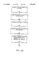
FIGS. 2a-b are flowcharts showing the components being configured by the diagnostic processor.
DETAILED DESCRIPTION OF THE INVENTION
Referring to the drawings more particularly by reference numbers, FIG. 1 shows a system 10 that contains a plurality of configurable components 12-18 that are coupled to a diagnostic processor 20. By way of example, the configurable components may be I/O ports and memory devices of a computer system.
Each component is coupled to the diagnostic processor 20 by a separate RESET line 22-28. The components are also coupled to the diagnostic 20 by a common ERROR # line 30 and data lines TDI 32-38. Configuration data is serially loaded into the components from the diagnostic processor 22 on the data lines TDI 32-38. Each component 12-18 has a plurality of shift registers 40 that store the configuration data. The system also has a test mode signal line (TMS) 42 that allows the diagnostic processor 22 to place the system in a test mode.
The diagnostic processor 20 contains a control circuit 44 and a data circuit 46. The data circuit 46 provides the configuration data to the components. The control circuit 46 contains logic to assert and deassert the RESET and TMS signals and control the flow of data to the components.
Upon power up or reset of the system, the control circuit 44 asserts the TMS signal 42 to place the system within the test mode. The control circuit 44 contains a state machine that then asserts the RESET signals 22-28 for each component 12-18 after a predetermined time interval.
The components each assert an ERROR # signal in response to the assertion of the RESET signals 22-28. When all of the RESET signals have been asserted, the control circuit 44 causes the data circuit 46 to sequentially load the configuration data into each component. After configuring the components, the diagnostic 20 sequentially deasserts the RESET signals 22-28 of each component. The components deassert the ERROR # signal 30 in response to the deassertion of the RESET signals. When all of the ERROR # signals have been deasserted the diagnostic 20 deasserts the TMS signal 42 and allows the system to operate in a normal mode.
In operation, as shown in processing block 100 the diagnostic processor 20 initially asserts the TMS signal 42 for the component 12-18. The processor 20 then asserts the RESET signals 22-28 for all of the components in block 102. The assertion of the RESET signals 22-28 typically occurs a predetermined number of clock cycles after the assertion of the TMS signal 42 to allow the components to stabilize. In response to the assertion of the RESET signal, the components each assert an ERROR # signal in block 104.
In processing block 106, while the RESET signals are asserted, the diagnostic 20 initially configures the first component 12 by providing a configuration data string which is loaded into the configuration registers of the component. After the first component 12 is configured, the diagnostic 20 configures the second component 14, then the third component 16 and so forth and so on, until all of the components are configured, as shown in block 108.
In processing block 110 the diagnostic processor 20 deasserts the RESET signal 22 for the first component 12. After a certain time interval the first component 12 deasserts its ERROR # signal in block 112. Because all of the ERROR # signals of the components are tied to the same line, the diagnostic 20 still senses an asserted ERROR # signal, even though the first components ERROR # signal has been deasserted. In block 114 the diagnostic processor 20 proceeds to deassert the RESET signal for the second component 14, then the third component 16 and so forth and so on, until the RESET signal for the last component has been deasserted. Each component deasserts its ERROR # signal in response to the deassertion of the RESET signal.
In processing block 116, when the last component has deasserted its ERROR # signal the diagnostic 20 senses a deasserted ERROR # signal 30 and allows normal operation of the system. The present invention assures that all components are in an active state before beginning normal operation of the system.
While certain exemplary embodiments have been described and shown in the accompanying drawings, it is to be understood that such embodiments are merely illustrative of and not restrictive on the broad invention, and that this invention not be limited to the specific constructions and arrangements shown and described, since various other modifications may occur to those ordinarily skilled in the art.

Claims (4)

What is claimed is:
1. A method for configuring a plurality of configurable components within a computer system, comprising the steps of:
a) asserting a test mode signal (TMS) to switch the computer system from a normal mode to a test mode;
b) asserting a first RESET signal for a first configurable component and a second RESET signal for a second configurable component;
c) asserting a first ERROR # signal by said first configurable component, wherein said first ERROR # signal is indicative of an inactive state of said first configurable component;
d) asserting a second ERROR # signal by said second configurable component, wherein said second ERROR # signal is indicative of an inactive state of said second configurable component;
e) loading a configuration data string into said first configurable component;
f) loading a configuration data string into said second configurable component;
g) deasserting said first RESET signal;
h) deasserting said first ERROR # signal;
i) deasserting said second RESET signal;
j) deasserting said second ERROR # signal; and,
k) deasserting said TMS signal to switch the computer system from the test mode to the normal mode.
2. A system that configures a plurality of configurable components in a computer system, comprising:
a plurality of configurable components that each have a plurality of configuration registers that can store configuration data in conjunction with an assertion of a RESET signal, each said configurable component asserts an ERROR # signal upon the assertion of said RESET signal and deasserts said ERROR # signal upon a deassertion of said RESET signal, said ERROR # signal being indicative of an inactive state of said configurable component; and,
a diagnostic processor that asserts a corresponding RESET signal and provides configuration dam to said configurable components while said RESET signal is asserted and deasserts said RESET signal after said configurable component stores the configurable data, said diagnostic processor asserts a test mode signal (TMS) to switch the computer system from a normal mode to a test mode before assertion of said RESET signal, and deasserts said TMS signal to switch the computer system from the test mode to the normal mode after all of said ERROR# signals of said configurable components have been deasserted.
3. The system as recited in claim 2, wherein said diagnostic processor sequentially loads configuration data strings into a plurality of configurable components while said RESET signal is asserted.
4. The system as recited in claim 3, wherein said diagnostic processor asserts RESET signals of said plurality of configurable components and sequentially deasserts said RESET signals after said configuration data strings are loaded into said configurable components.
US08/744,123 1994-07-20 1996-11-05 Method for initializing an array of configurable components Expired - Fee Related US5701420A (en)

Priority Applications (1)

Application Number Priority Date Filing Date Title
US08/744,123 US5701420A (en) 1994-07-20 1996-11-05 Method for initializing an array of configurable components

Applications Claiming Priority (2)

Application Number Priority Date Filing Date Title
US22759894A 1994-07-20 1994-07-20
US08/744,123 US5701420A (en) 1994-07-20 1996-11-05 Method for initializing an array of configurable components

Related Parent Applications (1)

Application Number Title Priority Date Filing Date
US22759894A Continuation 1994-07-20 1994-07-20

Publications (1)

Publication Number Publication Date
US5701420A true US5701420A (en) 1997-12-23

Family

ID=22853727

Family Applications (1)

Application Number Title Priority Date Filing Date
US08/744,123 Expired - Fee Related US5701420A (en) 1994-07-20 1996-11-05 Method for initializing an array of configurable components

Country Status (1)

Country Link
US (1) US5701420A (en)

Cited By (3)

* Cited by examiner, † Cited by third party
Publication number Priority date Publication date Assignee Title
WO1999013405A1 (en) * 1997-09-05 1999-03-18 Sonics, Inc. A fully-pipelined fixed-latency communications system with a real-time dynamic bandwidth allocation
US6216226B1 (en) * 1998-10-02 2001-04-10 International Business Machines Corporation Method and system for dynamically selecting a boot process within a data processing system
US20100138640A1 (en) * 2008-12-02 2010-06-03 Arm Limited Reset synchronisation

Citations (14)

* Cited by examiner, † Cited by third party
Publication number Priority date Publication date Assignee Title
US3680052A (en) * 1970-02-20 1972-07-25 Ibm Configuration control of data processing system units
US4150438A (en) * 1976-07-14 1979-04-17 The Solartron Electronic Group Ltd. Interfaces for connecting coded and non-coded data transmission systems
US4954983A (en) * 1987-10-13 1990-09-04 Tektronix, Inc. Data driver for multiple mode buffered processor-peripheral data transfer with selective return of data to processor
US4991085A (en) * 1988-04-13 1991-02-05 Chips And Technologies, Inc. Personal computer bus interface chip with multi-function address relocation pins
US5287531A (en) * 1990-10-31 1994-02-15 Compaq Computer Corp. Daisy-chained serial shift register for determining configuration of removable circuit boards in a computer system
US5305457A (en) * 1990-02-20 1994-04-19 Fujitsu Limited System for initial program loading responding to notification from program supply apparatus
US5325529A (en) * 1990-05-18 1994-06-28 Compaq Computer Corporation External boot information loading of a personal computer
US5336950A (en) * 1991-08-29 1994-08-09 National Semiconductor Corporation Configuration features in a configurable logic array
US5339432A (en) * 1992-10-13 1994-08-16 Microsoft Corporation Method and system for providing user control of device driver configuration
US5379431A (en) * 1993-12-21 1995-01-03 Taligent, Inc. Boot framework architecture for dynamic staged initial program load
US5386567A (en) * 1992-01-20 1995-01-31 International Business Machines Corp. Hot removable and insertion of attachments on fully initialized computer systems
US5410706A (en) * 1991-09-09 1995-04-25 Compaq Computer Corporation Computer system having a remote reboot facility with both hard and soft reset capabilities
US5446869A (en) * 1993-12-30 1995-08-29 International Business Machines Corporation Configuration and RAM/ROM control of PCI extension card residing on MCA adapter card
US5467295A (en) * 1992-04-30 1995-11-14 Intel Corporation Bus arbitration with master unit controlling bus and locking a slave unit that can relinquish bus for other masters while maintaining lock on slave unit

Patent Citations (14)

* Cited by examiner, † Cited by third party
Publication number Priority date Publication date Assignee Title
US3680052A (en) * 1970-02-20 1972-07-25 Ibm Configuration control of data processing system units
US4150438A (en) * 1976-07-14 1979-04-17 The Solartron Electronic Group Ltd. Interfaces for connecting coded and non-coded data transmission systems
US4954983A (en) * 1987-10-13 1990-09-04 Tektronix, Inc. Data driver for multiple mode buffered processor-peripheral data transfer with selective return of data to processor
US4991085A (en) * 1988-04-13 1991-02-05 Chips And Technologies, Inc. Personal computer bus interface chip with multi-function address relocation pins
US5305457A (en) * 1990-02-20 1994-04-19 Fujitsu Limited System for initial program loading responding to notification from program supply apparatus
US5325529A (en) * 1990-05-18 1994-06-28 Compaq Computer Corporation External boot information loading of a personal computer
US5287531A (en) * 1990-10-31 1994-02-15 Compaq Computer Corp. Daisy-chained serial shift register for determining configuration of removable circuit boards in a computer system
US5336950A (en) * 1991-08-29 1994-08-09 National Semiconductor Corporation Configuration features in a configurable logic array
US5410706A (en) * 1991-09-09 1995-04-25 Compaq Computer Corporation Computer system having a remote reboot facility with both hard and soft reset capabilities
US5386567A (en) * 1992-01-20 1995-01-31 International Business Machines Corp. Hot removable and insertion of attachments on fully initialized computer systems
US5467295A (en) * 1992-04-30 1995-11-14 Intel Corporation Bus arbitration with master unit controlling bus and locking a slave unit that can relinquish bus for other masters while maintaining lock on slave unit
US5339432A (en) * 1992-10-13 1994-08-16 Microsoft Corporation Method and system for providing user control of device driver configuration
US5379431A (en) * 1993-12-21 1995-01-03 Taligent, Inc. Boot framework architecture for dynamic staged initial program load
US5446869A (en) * 1993-12-30 1995-08-29 International Business Machines Corporation Configuration and RAM/ROM control of PCI extension card residing on MCA adapter card

Non-Patent Citations (3)

* Cited by examiner, † Cited by third party
Title
Designing with Microprocessors, Lawrence E. Getgen, 1985, pp. 51 64. *
Designing with Microprocessors, Lawrence E. Getgen, 1985, pp. 51-64.
Microsoft Press Computer Dictionary, 1993, pp. 10 & 334. *

Cited By (5)

* Cited by examiner, † Cited by third party
Publication number Priority date Publication date Assignee Title
WO1999013405A1 (en) * 1997-09-05 1999-03-18 Sonics, Inc. A fully-pipelined fixed-latency communications system with a real-time dynamic bandwidth allocation
US5948089A (en) * 1997-09-05 1999-09-07 Sonics, Inc. Fully-pipelined fixed-latency communications system with a real time dynamic bandwidth allocation
US6216226B1 (en) * 1998-10-02 2001-04-10 International Business Machines Corporation Method and system for dynamically selecting a boot process within a data processing system
US20100138640A1 (en) * 2008-12-02 2010-06-03 Arm Limited Reset synchronisation
US8250351B2 (en) * 2008-12-02 2012-08-21 Arm Limited Synchronization of two independent reset signals

Similar Documents

Publication Publication Date Title
US6519674B1 (en) Configuration bits layout
US5347181A (en) Interface control logic for embedding a microprocessor in a gate array
US5493723A (en) Processor with in-system emulation circuitry which uses the same group of terminals to output program counter bits
KR100376159B1 (en) Synchronous page-mode non-volatile memory
US5483660A (en) Method and apparatus for performing multiplexed and non-multiplexed bus cycles in a data processing system
US7679973B2 (en) Register file
US5832251A (en) Emulation device
US5249160A (en) SRAM with an address and data multiplexer
US7792154B2 (en) Controlling asynchronous clock domains to perform synchronous operations
US4821176A (en) Data processing arrangement using an interconnecting network on a single semiconductor chip
US6363501B1 (en) Method and apparatus for saving and loading peripheral device states of a microcontroller via a scan path
US6851014B2 (en) Memory device having automatic protocol detection
US20100122116A1 (en) Internally Controlling and Enhancing Advanced Test and Characterization in a Multiple Core Microprocessor
US5983339A (en) Power down system and method for pipelined logic functions
US6480974B1 (en) Method for use of bus parking states to communicate diagnostic information
EP0980040A3 (en) Data processing system
US5586047A (en) System for creating datapath circuit layout
KR970002661A (en) How to Configure Data Processing Systems and Data Processors
US20020146025A1 (en) Arbiter device for multi-port memory and semiconductor device
US5701420A (en) Method for initializing an array of configurable components
US5572718A (en) Mechanism for dynamically determining and distributing computer system clocks
US5797036A (en) Apparatus which prepares a master map portraying location of devices relative to bus interface circuits and copying the pertinent portion of the master map to each bus interface circuits
KR100640579B1 (en) Embedded MCU for high speed testing by memory emulation module and test method thereof
US10866608B2 (en) Apparatus and method of voltage regulation control for integrated circuit
US20050010832A1 (en) Method and apparatus of reducing scan power in the process of unloading and restoring processor content by scan chain partition and disable

Legal Events

Date Code Title Description
FEPP Fee payment procedure

Free format text: PAYOR NUMBER ASSIGNED (ORIGINAL EVENT CODE: ASPN); ENTITY STATUS OF PATENT OWNER: LARGE ENTITY

FPAY Fee payment

Year of fee payment: 4

FEPP Fee payment procedure

Free format text: PAYER NUMBER DE-ASSIGNED (ORIGINAL EVENT CODE: RMPN); ENTITY STATUS OF PATENT OWNER: LARGE ENTITY

Free format text: PAYOR NUMBER ASSIGNED (ORIGINAL EVENT CODE: ASPN); ENTITY STATUS OF PATENT OWNER: LARGE ENTITY

FPAY Fee payment

Year of fee payment: 8

REMI Maintenance fee reminder mailed
LAPS Lapse for failure to pay maintenance fees

Free format text: PATENT EXPIRED FOR FAILURE TO PAY MAINTENANCE FEES (ORIGINAL EVENT CODE: EXP.); ENTITY STATUS OF PATENT OWNER: LARGE ENTITY

STCH Information on status: patent discontinuation

Free format text: PATENT EXPIRED DUE TO NONPAYMENT OF MAINTENANCE FEES UNDER 37 CFR 1.362

FP Lapsed due to failure to pay maintenance fee

Effective date: 20091223