US5702491A - Portable hydrogen generator - Google Patents
Portable hydrogen generator Download PDFInfo
- Publication number
- US5702491A US5702491A US08/716,965 US71696596A US5702491A US 5702491 A US5702491 A US 5702491A US 71696596 A US71696596 A US 71696596A US 5702491 A US5702491 A US 5702491A
- Authority
- US
- United States
- Prior art keywords
- hydrogen
- water
- chemical hydride
- hydride
- container
- Prior art date
- Legal status (The legal status is an assumption and is not a legal conclusion. Google has not performed a legal analysis and makes no representation as to the accuracy of the status listed.)
- Expired - Fee Related
Links
Images


Classifications
-
- C—CHEMISTRY; METALLURGY
- C01—INORGANIC CHEMISTRY
- C01B—NON-METALLIC ELEMENTS; COMPOUNDS THEREOF; METALLOIDS OR COMPOUNDS THEREOF NOT COVERED BY SUBCLASS C01C
- C01B3/00—Hydrogen; Gaseous mixtures containing hydrogen; Separation of hydrogen from mixtures containing it; Purification of hydrogen
- C01B3/02—Production of hydrogen or of gaseous mixtures containing a substantial proportion of hydrogen
- C01B3/06—Production of hydrogen or of gaseous mixtures containing a substantial proportion of hydrogen by reaction of inorganic compounds containing electro-positively bound hydrogen, e.g. water, acids, bases, ammonia, with inorganic reducing agents
- C01B3/065—Production of hydrogen or of gaseous mixtures containing a substantial proportion of hydrogen by reaction of inorganic compounds containing electro-positively bound hydrogen, e.g. water, acids, bases, ammonia, with inorganic reducing agents from a hydride
-
- B—PERFORMING OPERATIONS; TRANSPORTING
- B01—PHYSICAL OR CHEMICAL PROCESSES OR APPARATUS IN GENERAL
- B01J—CHEMICAL OR PHYSICAL PROCESSES, e.g. CATALYSIS OR COLLOID CHEMISTRY; THEIR RELEVANT APPARATUS
- B01J7/00—Apparatus for generating gases
- B01J7/02—Apparatus for generating gases by wet methods
-
- Y—GENERAL TAGGING OF NEW TECHNOLOGICAL DEVELOPMENTS; GENERAL TAGGING OF CROSS-SECTIONAL TECHNOLOGIES SPANNING OVER SEVERAL SECTIONS OF THE IPC; TECHNICAL SUBJECTS COVERED BY FORMER USPC CROSS-REFERENCE ART COLLECTIONS [XRACs] AND DIGESTS
- Y02—TECHNOLOGIES OR APPLICATIONS FOR MITIGATION OR ADAPTATION AGAINST CLIMATE CHANGE
- Y02E—REDUCTION OF GREENHOUSE GAS [GHG] EMISSIONS, RELATED TO ENERGY GENERATION, TRANSMISSION OR DISTRIBUTION
- Y02E60/00—Enabling technologies; Technologies with a potential or indirect contribution to GHG emissions mitigation
- Y02E60/30—Hydrogen technology
- Y02E60/36—Hydrogen production from non-carbon containing sources, e.g. by water electrolysis
Definitions
- the present invention relates to a hydrogen generator, and more particularly to a lightweight, portable and nearly adiabatic hydrogen generator and to a method for generating hydrogen.
- Hydrogen generators have long been used to generate hydrogen through the hydrolysis of chemical hydrides, and in particular, metal hydrides.
- U.S. Pat. No. 2,334,211 discloses a hand-held generator containing calcium hydrides which, when submersed in water, produces sufficient hydrogen to fill an emergency signal balloon.
- the most common portable source of hydrogen is hydrogen bottles or tanks in which the hydrogen is stored under pressure. The hydrogen stored in these bottles or tanks is generated at a hydrogen production plant, shipped as a cryogenic liquid, vaporized, and expanded into the tanks or bottles under pressure.
- These hydrogen tanks or bottles are generally bulky and rather heavy. Further, when a tank or bottle is exhausted, it must be replaced with another tank or bottle.
- Storage tanks or bottles are utilized in field applications because, typically, hydrogen production facilities have been considered too large, too heavy, too expensive and in many instances, too unsafe, for portable operation. In response, there have been attempts to develop practical and portable hydrogen generators.
- U.S. Pat. No. 4,155,712 discloses a small portable hydrogen generator utilizing a metal hydride and water vapor in which hydrogen can be automatically produced on demand or at a constant pressure feed over widely varying hydrogen demand rates without water supply contamination or metal hydride caking complications.
- demand responsive hydrogen generators however, is that of a sudden requirement made on the water vapor such that water instead of the water vapor could be drawn into direct contact with the fuel, thus causing a malfunction.
- U.S. Pat. No. 4,261,955 addresses this problem by utilizing a wall means for separating adjacently disposed solid fuel and water compartments.
- the wall means includes two spaced apart porous hydrophobic membranes.
- the membranes are of a character as to normally only pass water vapor from the water supply to the fuel compartment. If an abnormal demand is made on the water vapor, it could inadvertently cause unvaporized water to pass through one of the membranes. Therefore, a hydrogen gas outlet is positioned between the spaced-apart membranes to pull off the water before it could reach the metal hydride fuel.
- an improved hydrogen generator is needed which is lightweight, compact, portable, and temperature safe and which provides a controllable flow of hydrogen upon demand.
- the present invention employs an adiabatic hydrolysis and thermal decomposition of a chemical hydride to provide a controllable generation of hydrogen from a small, lightweight, portable and hand handleable container.
- a preferred hydrogen generator of the invention includes a thermally isolated container for containing a first chemical hydride; heating means for heating the first chemical hydride to a predetermined temperature; a water supply for hydrolysis of the first chemical hydride only after the first chemical hydride reaches the predetermined temperature; a buffer, or recovery device, for recovering hydrogen from the container; and a control unit for controlling the rate of generation of hydrogen by the hydrogen generator.
- the buffer is also used for hydrogen generation during startup and for smoothing hydrogen production rates to follow demand variations.
- the container comprises a dewar having an outer shell and an inner vessel defining an evacuated space therebetween, and having an insulating material positioned in the evacuated space, wherein the first chemical hydride is placed within the inner vessel.
- the first chemical hydride is a metal hydride, and more preferably, a metal hydride having at least one metal taken from a group consisting of the metals found in the first three rows of the periodic chart.
- a metal hydride can be a ternary composition, such as for example, a ternary composition consisting essentially of LiAlH 4 .
- the heating unit heats the first chemical hydride to a temperature greater than about 100 degrees C.
- a heating unit can include a chemical composition, including, for example, a second chemical hydride positioned in the container between the first chemical hydride and the water supply for generating an exothermic reaction when the chemical composition is combined with water.
- the heating unit may include an electrical heater.
- the water supply includes a water source, a water pump hydraulically coupled to the water source and electrically coupled to the control means, and a water conduit coupled between the water pump and the container.
- the water supply further includes an annular filter positioned in the container adjacent to an outlet of the water conduit.
- the second chemical hydride is a mixture of a compressible porous medium and a chemical hydride positioned between the annular filter and the first chemical hydride. The mixture prevents caking and increase porosity of the second chemical hydride.
- the hydrogen buffer includes an outlet conduit coupled to the container, a buffer chamber coupled to the outlet conduit, and a rechargeable hydride positioned in the buffer chamber.
- the rechargeable hydride supplies hydrogen to the outlet conduit whenever the hydrogen demand exceeds the rate of generation by the chemical hydrides. It also absorbs excess hydrogen after the water supply has been stopped from supplying water to the container by the control unit.
- the rechargeable hydride is a metal hydride.
- the hydrogen generator further includes a control unit for controlling an amount of hydrogen generated.
- the control unit includes a pressure switch coupled to the hydrogen conduit, wherein the pressure switch senses a pressure of the hydrogen to generate a signal corresponding to the pressure of the hydrogen.
- the pressure switch is coupled to the water source to control a flow of water to the container based on the pressure signal. Thus, the control unit controls the rate of hydrogen generation.
- the chemical composition In preferred hydrogen generators, the chemical composition generates sufficient heat to raise the temperature of the preferred LiAlH 4 above about 100 degrees C. prior to the hydration of the LiAlH 4 .
- the chemical composition includes a second metal hydride, such as CaH 2 or other similar hydride, and a compressible porous medium, such as vermiculite.
- a second metal hydride such as CaH 2 or other similar hydride
- a compressible porous medium such as vermiculite.
- the invention comprises a hydrogen generator, including a container; a water source having a water conduit for supplying water into the container; a first chemical hydride placed in the container; a chemical composition positioned in the container between the first chemical hydride and an outlet of the water conduit, the chemical composition being adapted to react with water supplied from the outlet of the water conduit to heat the first chemical hydride, and delay hydration of the first chemical hydride until it has reached a temperature sufficient to prevent the first chemical hydride from undergoing an unstable exothermic reaction; and a buffer for recovering hydrogen from the container.
- a preferred method of the invention includes the steps of placing a first chemical hydride in a thermally isolated container; heating the first chemical hydride to a predetermined temperature; hydrolyzing the first chemical hydride only after the first chemical hydride reaches the predetermined temperature; recovering hydrogen from the container; and controlling an amount of hydrogen generated by the hydrogen generator. The entire process balances the exothermic chemical reaction with the endothermic decomposition in the first chemical hydride.
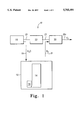
- FIG. 1 shows a general block diagram of a hydrogen generator embodying the invention.
- FIG. 2 shows a graph of hydrogen production during the various hydrolysis and thermal decomposition stages of LiAlH 4 .
- FIG. 3 shows a combined pictorial and block representation of a first embodiment of the invention.
- FIG. 4 shows a combined pictorial and block representation of a second embodiment of the invention.
- FIG. 1 shows a hydrogen generator 10 embodying the invention.
- Hydrogen generator 10 includes a thermally isolated container 12, such as a vacuum insulated, multiple wall dewar similar to a cryogenic dewar, containing a primary chemical hydride 14, preferably a metal hydride, such as, for example, lithium aluminum hydride (LiAlH 4 ).
- Primary chemical hydride 14 undergoes both hydrolysis and thermal decomposition reactions to generate hydrogen (H 2 ).
- hydrolysis is the exothermic chemical reaction of a chemical hydride, such as LiAlH 4 , with water to form oxides or hydroxides and hydrogen. Endothermic decomposition occurs in the chemical hydride when the heat completes the reaction to form hydrogen and other byproducts.
- a chemical hydride such as LiAlH 4
- a heating unit 16 is positioned adjacent chemical hydride 14 and, when activated, heats primary chemical hydride 14 to a pre-determined temperature (preferably about 100 degrees C. for LiAlH 4 ). Activation of heating unit 16 avoids chemical reactions associated with primary chemical hydride 14 which can result in large water release, and, thus, avoids an uncontrollable hydrogen release and an increase in pressure in container 26 during initial hydration of primary chemical hydride 14.
- Water supply 18 supplies water into a water conduit 19, which in turn is coupled to container 12. After primary chemical hydride 14 reaches the predetermined temperature (about 100 degrees C. for LiAlH 4 ), the water from conduit 19 is converted to steam which permeates into primary chemical hydride 14, thereby hydrolyzing chemical hydride 14 to generate hydrogen. The rate of hydrogen generation from primary chemical hydride 14 is determined, in primary part, by the rate that water is supplied to container 12 by water supply 18.
- a buffer 20 is coupled to container 12 via a conduit 21 for recovering the hydrogen generated inside container 12 during the hydrolysis and thermal decomposition of primary chemical hydride 14.
- Buffer 20 includes an outlet 20a for supplying an output flow of hydrogen for use by a device (not shown) such as, for example, a fuel cell, a space craft thruster, a hydrogen burner, a storage vessel, etc.
- Buffer 20 further serves to supply an initial flow of hydrogen to outlet 20a during the initial start-up of hydrogen generator 10, as well as absorb excess hydrogen generated after hydrogen generator 10 is commanded to stop generating hydrogen.
- buffer 20 contains a rechargeable hydride buffer material, such as a metal hydride, which is capable of supplying an initial flow of hydrogen upon start-up of hydrogen generator 10, and of absorbing excess hydrogen generated when hydrogen generator 10 is commanded to stop hydrogen production.
- a rechargeable hydride buffer material such as a metal hydride
- a control unit 22 is provided for controlling an amount of hydrogen generated by hydrogen generator 10.
- Control unit 22 can be, for example, a pressure switch coupled to buffer 20 via a conduit 23.
- Control unit 22 senses a hydrogen pressure of container 12 and buffer 20, and generates therefrom a control signal which is supplied, via a conductor 25, to water supply 18 to control the flow of water from water supply 18 to container 12, thereby controlling the hydrolysis of primary chemical hydride 14, and, thus, the flow of hydrogen generated by primary chemical hydride 14 and supplied to buffer 20.
- control unit 22 can be a simple switch to control water supply 18 in an ON-OFF fashion, it is contemplated that control unit 22 can include a controller for receiving multiple pressure inputs and temperature inputs which can be utilized to provide more precise control over the flow of water supplied to container 12.
- Preferred embodiments of the invention provide a significant weight reduction over prior generators by eliminating the need for a high pressure hydrogen storage tank to absorb excess hydrogen production and supply hydrogen when demand exceeds production, as well as by allowing the portion of container 12 which contains the primary chemical hydride to be made from lighter gauge materials due to the buffer characteristic of buffer 20. Preferred embodiments of the invention also avoid the need for a heat rejection system by balancing the exothermic hydrolysis rate and the endothermic decomposition inside an isolated thermal container.
- the primary chemical hydride 14 In order for hydrogen generator 10 to remain an ultra lightweight unit, however, the primary chemical hydride 14 must be based upon chemical hydrides which bind a relatively high percentage of hydrogen per unit weight.
- Prime candidates for the primary chemical hydride 14 include chemical hydrides based upon one or more of the elements from the first three rows in the periodic chart, which include metals such as lithium, beryllium, magnesium and aluminum.
- Lithium, sodium and magnesium react directly with hydrogen, under commercially convenient pressures and temperature conditions, to form the binary metal hydrides LiH, NaH, and MgH 2 .
- Aluminum hydride (AlH 3 ) can be made directly at very high pressures, but it is usually formed in solution. The latter method of forming AlH 3 , however, results in solvent contamination that is objectionable for some applications, such as for use with fuel cells.
- the primary candidates for use with hydrogen generator 10 as the primary chemical hydride 14 are the ternary hydrides including commercially available LiAlH 4 , NaAlH 4 , LiBH 4 and NaBH 4 .
- Other ternary hydrides, such as Mg(AlH 4 ) 2 and liquid Al(BH 4 ) 3 are also contemplated for possible use with hydrogen generator 10.
- Table I shows the thermal decomposition capabilities of several candidate metal hydrides in order of weight percentage (w/o) of hydrogen evolved, assuming complete thermal decomposition.
- the thermal decomposition of metal hydrides is generally less than 100% complete due to hydrogen solution in the metal phase.
- the definition of weight percent (w/o) used herein is the weight of hydrogen divided by the total weight of the reactants, including hydrogen.
- Table II shows the hydrogen generation capacities, via excess water reactions in weight percent (w/o), of prime candidate metal hydrides.
- the "Stored Water” column includes the weight of the water shown on the left side of the reaction.
- the “Product Water” column excludes water weight.
- Several of the hydroxide products listed in Table II also form hydrates. Hydroxides and hydrates decompose at elevated temperatures, thereby liberating steam in the process. If the thermal decomposition of the hydroxides or hydrates occurs to generate H 2 O in the presence of unreacted hydrides, an uncontrolled reaction proceeds with potentially dangerous results.
- the hydrogen pressure which can be produced by these reactions is virtually unlimited. Thus, it is important to precisely control water inventory in container 12 at all times.
- Hydrides that are thermally stable and form hydroxides upon reaction with excess water at room temperature become less stable and less prone to form hydroxides with increasing temperature.
- Calcium hydride (CaH 2 ) reacts with water to form the hydroxide (Ca(OH) 2 ) at room temperature. Above 400 degrees C., the product of the water reaction is the oxide (CaO). Any hydroxide formed below 400 degrees C. decomposes endothermically above 580 degrees C., liberating water. If there is any unreacted hydride present when the water is released, it will react instantaneously producing H 2 and CaO. The hydride itself decomposes thermally above 600 degrees C.
- Magnesium hydride (MgH 2 ) is similar to CaH 2 , forming a hydroxide at lower temperatures. But, unlike CaH 2 , MgH 2 decomposes thermally at a lower temperature (280 degrees C.) than its hydroxide (350degrees C.). Lithium hydroxide is stable to its melting point, 450 degrees C. Accordingly, knowledge of the details of all reactions wherein hydrogen or water consumed or released is essential for the effective use of a chemical hydrogen generator.
- the preferred chemical hydride for use with hydrogen generator 10 is lithium aluminum hydride (LiAlH 4 ).
- LiAlH 4 is a white microcrystalline powder that turns gray due to aluminum precipitates due to thermal decomposition. LiAlH 4 also hydrolyzes slowly in air due to humidity.
- the hydrolysis and thermal decomposition chemistry of LiAlH 4 provides an abundance of hydrogen per unit weight, and LiAlH 4 decomposes in a complex manner which can be controlled with temperature and carefully metered water addition. LiAlH 4 reacts spontaneously and violently with liquid water, uncontrollably decomposing to give off hydrogen gas and heat.
- Table III shows all the known reactions of LiAlH 4 , including both hydrolysis (Hydro.) and thermal decomposition (Therm.), as defined above, for producing hydrogen and other byproducts.
- the hydrolysis chemistry of LiAlH 4 divides into two classes: efficient water and inefficient water, often referred to as insufficient water and excessive water, respectively.
- Reaction No. 3 of Table III shows, for example, the efficient (insufficient) water hydrolysis reaction.
- one mole of water produces two moles of hydrogen.
- Reaction Nos. 1 and 7 of Table III shows examples of the inefficient (excessive) water hydrolysis reaction.
- the inefficient water reaction requires one mole of water to generate one mole of hydrogen. Regardless of whether water is a limiting or excess reagent, the observed enthalpy, or heat of hydrolysis, in both the efficient and inefficient cases is approximately the same, and is approximately 700 kJ ⁇ mole.
- FIG. 2 shows, during the time period between 0 and 5000 seconds, the amount of hydrogen and heat generated in container 12 if preheating is not provided.
- hydrogen generation and temperatures in container 12 increases dramatically at about 4000 seconds due to the production of excess water which in turn reacts with available LiAlH 4 to release more hydrogen when the temperature of the LiAlH 4 reaches about 100 degrees C.
- reaction Nos. (1) and (2) in Table III it is desired to avoid reaction Nos. (1) and (2) in Table III to avoid the problems associated with uncontrolled water release.
- the LiAlH 4 chemical hydride 14 is heated by heating unit 16 to about 100 degrees C. prior to hydrolysis of the primary chemical hydride 14 to generate hydrogen.
- container 12 preferably a vacuum-insulated dewar similar to the dewars used to contain cryogens, allows the hydrogen generator 10 to be adiabatic to both conserve and use the heat generated above 100 degrees C.
- the heat above 115 degrees C. generated by exothermic hydrolysis reaction of the LiAlH 4 (reaction No. 3 of Table III) is used to generate additional hydrogen by the endothermic thermal decomposition (reaction No. 4 of Table III), which in turn lowers the temperature in container 12.
- reaction No. 4 of Table III the endothermic thermal decomposition
- dewar container 12 also prevents the outer surface thereof from heating, thus allowing the system to be packaged without substantial thermal material expansions and contractions.
- hydrogen generator 10 provides a light weight, portable, and nearly adiabatic, constant volume hydrogen generator.
- the hydrogen generator 10 of FIG. 1 will now be described with reference to the preferred embodiments shown in FIGS. 3 and 4.
- the preferred embodiments of FIGS. 3 and 4 identify hydrogen generator 10 of FIG. 1 as hydrogen generators 10a and 10b, respectively.
- Hydrogen generators 10a and 10b differ primarily in the manner in which primary chemical hydride 14 is heated and in the timing for supplying water to the hydrogen generator through conduit 19. Therefore, to avoid undue repetition, where possible, the common features of the two embodiments will be discussed together using common element numbers, and structural differences will be identified as they are discussed.
- container 12 comprises a thermally isolated dewar having an outer shell 24 and an inner vessel 26 which combine to define a vacuum space 27 therebetween.
- Thermal insulation 28 is positioned in vacuum space 27 to form an annular insulating wall around inner vessel 26.
- Vacuum space 27 may be filled with an insulating material, such as fiberglass, multilayer material, or other insulating materials.
- the generation of hydrogen by hydrogen generator 10 primarily occurs in inner vessel 26 of container 12, wherein the primary chemical hydride 14 (preferably LiAlH 4 ) is contained.
- Inner vessel 26 is preferably made from materials, such as stainless steel and the like, which can accommodate the positive pressures occurring therein during hydrogen generation, as well as accommodate temperatures which can exceed 300 degrees C.
- the primary chemical hydride 14 is gradually heated and the hydrolysis and thermal decomposition of primary chemical hydride 14 results in a slow increase in temperature in inner vessel 26, as shown for example in FIG. 2 from 5000 to 15000 seconds.
- Outer shell 24, however, remains substantially at ambient temperature due to the thermal isolation resulting from the vacuum 27 and the insulation 28 between inner vessel 26 and outer shell 24 of container 12.
- the thermal isolation of container 12 thermally isolates the primary chemical hydride 14 from the ambient conditions external to container 12. Therefore, the heat generated during hydrolysis of primary chemical hydride 14 (see, for example, reaction No. 3, Table III) is available to promote further thermal decomposition of primary chemical hydride 14 into hydrogen through induced thermal reactions (see reactions Nos. 4 and 6, Table III).
- the thermal decomposition of primary chemical hydride 14 is an endothermic reaction which absorbs at least a portion of the heat generated during hydrolysis of primary chemical hydride 14, thereby stabilizing the temperature inside inner vessel 26 below the temperature which would have resulted if no such endothermic reaction occurred.
- hydrogen generator 10 is maintained substantially adiabatic.
- the preferred hydride for primary chemical hydride 14 is a metal hydride having at least one metallic element taken from a group consisting of the metals found in the first three rows of the periodic chart.
- this metal hydride is a ternary composition, such as for example, lithium aluminum hydride (LiAlH 4 ).
- annular filters 30a and 30b are also contained in inner vessel 26 .
- Filter 30a is positioned in a lower portion of inner vessel 26 and is used to filter H 2 O, in the forms of either liquid or vapor, entering inner vessel 26.
- Annular filter 30a distributes the liquid or water vapor entering inner vessel 26 around the lower outer region of inner vessel 26.
- Filter 30b is positioned in the upper region of inner vessel 26 for filtering the generated hydrogen which has migrated to the top of inner vessel 26.
- heating unit 16 is positioned near a lower portion of inner vessel 26.
- heating unit 16 is an electric heater 16a, preferably a silicon heater, positioned adjacent to an outer surface of inner vessel 26. Electrical energy is supplied to electrical heater 16a by an electrical source (not shown).
- electrical heater 16a supplies heat to the side-walls 26a of inner vessel 26, and accordingly, supplies heat to primary chemical hydride 14 (LiAlH 4 ).
- controller 46 supplies a signal to a pump 36 of water supply 18 via conductor 31, and pump 36 responds by supplying a metered amount of water via conduit 19 to inner vessel 26.
- Water supply 18 includes a water source 32 coupled via a water conduit 34 to pump 36.
- Pump 36 is coupled at its output 36a to conduit 19. Since chemical hydride 14 and inner vessel 26 are at a temperature of about 100 degrees C., when the water reaches a lower conduit portion 19a of conduit 19, the liquid water is converted to water vapor or steam, which then exits conduit outlet 19b, permeates annular filter 30a, and is in turn distributed annularly in a lower inner region 26b of inner vessel 26. The steam then passes through primary chemical hybrid LiAlH 4 to generate hydrogen, initially, according to reaction No. 3 of Table III.
- controller 46 can receive temperature feedback signals from one or more of the thermocouples 54-56 via electrical conductors 58-60, respectively, which are positioned at various levels inside inner vessel 26. Thus, once the temperature of chemical hydride 14 reaches the predetermined, substantially uniform temperature, controller 46 generates a signal to activate pump 36 for starting water delivery to inner vessel 26.
- the quantity of water supplied to inner vessel 26 is metered so as to promote controllable and sustained hydrolysis and thermal decomposition of primary chemical hydride 14 to generate hydrogen through the complementary exothermic and endothermic reactions identified, for example, as reaction Nos. (3)-(7) in Table III.
- the hydrogen generated by the primary chemical hydride 14 migrates to the upper region of inner vessel 26, and flows through filter material 30b as the hydrogen exits inner vessel 26 via conduit 21 and is supplied to hydrogen buffer 20.
- heating unit 16 comprises a chemical heating composition 16b.
- a supplemental electrical heater 16a can be provided adjacent to sidewall 26a of inner vessel 26 to provide auxiliary heating capacity, if needed.
- water supply 18 begins immediately to supply water to inner vessel 26 via water conduit 19.
- Controller 46 actuates, via conductor 31, pump 36 which provides a metered flow of water through conduit 19 into inner vessel 26.
- Conduit 19 extends vertically to the lower region of inner vessel 26 and supplies liquid water through its output 19b to annular filter 30a. The water permeates filter 30a and is distributed to the outer surface of filter material 30a to begin hydrolysis of chemical heating composition 16b.
- heating composition 16b is a combination of a metal hydride, such as calcium hydride (CaH 2 or other similar hydrides), and a compressible porous medium, such as vermiculite.
- a metal hydride such as calcium hydride (CaH 2 or other similar hydrides)
- CaH 2 or other similar hydrides undergo an exothermic hydrolysis to produce hydrogen and heat, and the heat produced thereby raises the temperature of the composition 16b, the supplied water and the primary chemical hydride 14.
- the supplied water is converted to water vapor which then permeates through the second chemical hydride mixture 16b, to reach primary chemical hydride 14.
- the heated chemical hydride 14 is further heated by the steam and reacts, initially, according to the exothermic hydrolysis reaction of reaction No. 3 of Table III.
- Pump 36 meters the amount of water entering inner vessel 26 so as to prevent to premature saturation of primary chemical hydride 14, and thereafter promotes a controlled and sustained reactions in primary chemical hydride 14 to generate hydrogen through complimentary exothermic and endothermic reactions of the reaction No. (3) through (7) shown in Table III.
- Pump 36 may be effectually operated by a "bang-bang" controller, i.e. on-off, in response to the internal pressure within inner vessel 26.
- the heat of vaporization of the supplied water and of the exothermic/endothermic chemical conversations of the primary and secondary chemical hydrides counteract to provide a substantially adiabatic process without the generation of unacceptably high temperatures within the inner vessel.
- the hydrogen generated by the heating composition 16b and primary chemical hydride 14 migrates to the upper region of inner vessel 26, and flows through filter material 30b as the hydrogen exits inner vessel 26 via conduit 21 and is supplied to the hydrogen buffer 20.
- Hydrogen buffer 20 shown in FIGS. 3 and 4 includes hydrogen conduits 40 and 42, and a rechargeable metal hydride buffer 44.
- Rechargeable hydride buffer 44 provides a receptacle 44a containing a buffer material 44b which serves as a low pressure hydrogen storage medium capable of both supplying hydrogen and absorbing hydrogen.
- the buffer material 44b is a rare earth pentanickel alloy, such as "Alloy M" sold by Hydrogen Consultants, Inc. of 12420 North Dumont Way, Littleton, Colo. or a pentanickel alloy.
- the amount of rechargeable hydride needed varies according to the size and duty cycle of the prescribed load.
- Rechargeable hydride buffer 44 provides efficient start-up and shut-down of hydrogen generator 10 by generating the initial flow of hydrogen during start-up and absorbing excess hydrogen generated during shut-down. It also buffers variation in the hydrogen demand during operation.
- buffer material 44b of rechargeable metal hydride buffer 44 Upon initial start-up of hydrogen generator 10a and 10b shown in FIGS. 3 and 4, buffer material 44b of rechargeable metal hydride buffer 44 generates an initial output of hydrogen which is supplied to outlet. During this time, primary chemical hydride 14 is being heated by heating unit 16 (i.e., the electrical heater 16a of hydrogen generator 10a, or the chemical heating composition 16b of hydrogen generator 10b) to the predetermined temperature of about 100 degrees C. In hydrogen generator 10b of FIG. 4, however, hydrogen generation begins in inner vessel 26 by the hydrolysis of heating composition 16b. Thus, in hydrogen generator 10b of FIG. 4, rechargeable metal hydride buffer material 44b and heating composition 16b both contribute hydrogen for meeting the initial flow requirements of a device coupled to outlet 20a.
- heating unit 16 i.e., the electrical heater 16a of hydrogen generator 10a, or the chemical heating composition 16b of hydrogen generator 10b
- primary chemical hydride 14 After primary chemical hydride 14 reaches a temperature of 100 degrees C., the primary chemical hydride is hydrolyzed with steam which is formed in conduit 19, and the primary chemical hydride 14 becomes the major contributor to the total output of hydrogen from hydrogen generators 10a and 10b.
- controller 46 commands pump 36 to cease water delivery to inner vessel 26; however, hydrogen continues to be generated in inner vessel 26 until the water contained therein is depleted.
- excess hydrogen generated prior to water depletion in inner vessel 26 is absorbed by the buffer metal hydride 44b in rechargeable hydride buffer 44. Buffer 44 also serves to smooth hydrogen demand swings during normal operation.
- control unit 22 includes a pressure switch 48 to sense the hydrogen pressure in hydrogen conduit 40 and to generate a signal to reduce or cutoff the flow of water provided by pump 36. As shown in FIGS. 3 and 4, pressure switch 48 is coupled to hydrogen conduit 21 via hydrogen conduit 23.
- pressure switch 48 senses the hydrogen pressure in conduit 21, which is coupled to inner vessel 26, and when the sensed pressure reaches the predetermined trigger point of pressure switch 48, pressure switch 48 generates a stop signal which is supplied to pump 36 via electrical conductor 25. Pump 36 responds by stopping the flow of water to inner vessel 26. When the pressure sensed by pressure switch 48 decreases below the trigger point, pressure switch supplies a run signal to pump 36, and pump 36 responds by metering additional water to inner vessel 26 for hydrolysis of the primary chemical hydride 14. Thus, pressure switch 48 cycles pump 36 ON and OFF in relation to the hydrogen pressure in inner vessel 26.
- thermocouples 54, 55 and 56 are arranged to sense the temperatures at the lower, upper and mid regions, respectively, of primary chemical hydride 14 in inner vessel 26.
- Thermocouples 54, 55 and 56 are electrically coupled to controller 46 via electrical conductors 58, 59 and 60, respectively. From the thermocouple outputs of thermocouples 54-56, controller 46 generates a temperature display which is readable by a human observer.
- controller 46 uses the temperature feedback signals received from thermocouples 54-56 to generate a signal which is supplied to pump 36 via electrical conductor 31 to control or stop pump 36 from supplying water to inner vessel 26, if a temperature in inner vessel 26 exceeds a maximum acceptable value, such as for example, 300 degrees C., or has not yet reached an acceptable temperature, such as for example 100° C., as explained above.
- a maximum acceptable value such as for example, 300 degrees C.
- an acceptable temperature such as for example 100° C.
- the invention described in the various preferred embodiments above provides a lightweight and portable hydrogen generator which is substantially adiabatic.
- the inner container 26 is temperature controlled while the outer container 12 remains at ambient temperature.
Abstract
Description
              TABLE I
______________________________________
       Hydride
             Thermal Decomposition
______________________________________
       LiH   12.7         w/o
       LiAlH.sub.4
             10.6         w/o
       AlH.sub.3
             10.1         w/o
       MgH.sub.2
             7.7          w/o
       NaH   4.2          w/o
______________________________________
              TABLE II
______________________________________
Error| Reference source
not fount. Excess Water
                    Stored   Product
Reaction            Water    Water
______________________________________
LiH + H.sub.2 O → LiOH + H.sub.2
                    7.5   w/o    29.1  w/o
LiAlH.sub.4 + 4H.sub.2 O → LiAl(OH).sub.4 + 4H.sub.2
                    7.3   w/o    21.2  w/o
AlH.sub.3 + 3H.sub.2 O → Al(OH).sub.3 + 3H.sub.2
                    7.2   w/o    20.2  w/o
MgH.sub.2 + 2H.sub.2 O → Mg(OH).sub.2 + 2H.sub.2
                    6.3   w/o    14.2  w/o
NaH + H.sub.2 O → LiOH + H.sub.2
                    4.7   w/o    8.8   w/o
______________________________________
                                  TABLE III
__________________________________________________________________________
   Approx.
   Temperature                 Type of
No.
   in degrees C.
         Reaction              Reaction
                                    H.sub.2 /H.sub.2 O
__________________________________________________________________________
1  <100  LiAlH.sub.4 + 4H.sub.2 O → LiAl(OH).sub.4 + 4H.sub.2 +
         Heat                  Hydro.
                                    1.0
2  >100  LiAl(OH).sub.4 + Heat → LiAlO.sub.2 + 2H.sub.2 O
                               Therm.
3  >100  LiAH.sub.4 + 2H.sub.2 O → LiAlO.sub.2 + 4H.sub.2 +
                               Hydro.
                                    2.0
4  100-150
         3LiAlH.sub.4 + Heat → Li.sub.3 AlH.sub.6 + 2Al
                               Therm.ub.2
5  >150  Li.sub.3 AlH.sub.6 + 4H.sub.2 O = 2LiOH + LiAlO.sub.2 + 6H.sub.2
         + Heat                Hydro.
                                    1.5
6  >220  2Li.sub.3 AlH.sub.6 + Heat → 6LiH + 2Al
                               Therm.ub.2
7  >220  LiH + H.sub.2 O → LiOH + H.sub.2 + Heat
                               Hydro.
                                    1.0
__________________________________________________________________________
Claims (6)
Priority Applications (1)
| Application Number | Priority Date | Filing Date | Title |
|---|---|---|---|
| US08/716,965 US5702491A (en) | 1995-06-07 | 1996-09-20 | Portable hydrogen generator |
Applications Claiming Priority (2)
| Application Number | Priority Date | Filing Date | Title |
|---|---|---|---|
| US08/476,729 US5593640A (en) | 1995-06-07 | 1995-06-07 | Portable hydrogen generator |
| US08/716,965 US5702491A (en) | 1995-06-07 | 1996-09-20 | Portable hydrogen generator |
Related Parent Applications (1)
| Application Number | Title | Priority Date | Filing Date |
|---|---|---|---|
| US08/476,729 Division US5593640A (en) | 1995-06-07 | 1995-06-07 | Portable hydrogen generator |
Publications (1)
| Publication Number | Publication Date |
|---|---|
| US5702491A true US5702491A (en) | 1997-12-30 |
Family
ID=23893012
Family Applications (2)
| Application Number | Title | Priority Date | Filing Date |
|---|---|---|---|
| US08/476,729 Expired - Fee Related US5593640A (en) | 1995-06-07 | 1995-06-07 | Portable hydrogen generator |
| US08/716,965 Expired - Fee Related US5702491A (en) | 1995-06-07 | 1996-09-20 | Portable hydrogen generator |
Family Applications Before (1)
| Application Number | Title | Priority Date | Filing Date |
|---|---|---|---|
| US08/476,729 Expired - Fee Related US5593640A (en) | 1995-06-07 | 1995-06-07 | Portable hydrogen generator |
Country Status (1)
| Country | Link |
|---|---|
| US (2) | US5593640A (en) |
Cited By (76)
| Publication number | Priority date | Publication date | Assignee | Title |
|---|---|---|---|---|
| WO2001068517A1 (en) * | 2000-03-17 | 2001-09-20 | Hydro-Quebec | Method for producing gaseous hydrogen by chemical reaction of metals or metal hydrides subjected to intense mechanical deformations |
| WO2001074710A1 (en) * | 2000-03-30 | 2001-10-11 | Manhattan Scientifics, Inc. | Portable chemical hydrogen hydride system |
| WO2001074711A1 (en) * | 2000-04-04 | 2001-10-11 | Zakrytoe Aktsionernoe Obschestvo 'firma Rikom' | The method of burning metal fuel |
| EP1170249A1 (en) * | 2000-07-03 | 2002-01-09 | Toyota Jidosha Kabushiki Kaisha | Fuel gas generation system and generation method thereof |
| US6418275B1 (en) * | 2001-04-16 | 2002-07-09 | Asia Pacific Fuel Cell Technologies, Ltd. | Supply device for use with a hydrogen source |
| WO2003041188A2 (en) * | 2001-11-09 | 2003-05-15 | Hydrogenics Corporation | Chemical hydride hydrogen generation system and fuel cell stack incorporating a common heat transfer circuit |
| US20030113259A1 (en) * | 2001-12-17 | 2003-06-19 | Ali Rusta-Sallehy | Chemical hydride hydrogen reactor and generation system |
| US20030162059A1 (en) * | 2002-02-28 | 2003-08-28 | Jon Gelsey | Thermally efficient hydrogen storage system |
| US20030180587A1 (en) * | 2000-09-01 | 2003-09-25 | Jones Peter Brian | Portable hydrogen source |
| US20040009379A1 (en) * | 2002-07-11 | 2004-01-15 | Amendola Steven C. | Method and apparatus for processing discharged fuel solution from a hydrogen generator |
| US20040052722A1 (en) * | 2002-09-12 | 2004-03-18 | Jorgensen Scott Willis | Hydrogen generation system using stabilized borohydrides for hydrogen storage |
| US20040052704A1 (en) * | 2002-09-16 | 2004-03-18 | Devos John A. | Gas generation system |
| US20040071630A1 (en) * | 2002-10-11 | 2004-04-15 | Jorgensen Scott Willis | Method of generating hydrogen by reaction of borohydrides and hydrates |
| US6745105B1 (en) * | 1999-05-12 | 2004-06-01 | Stuart Energy Systems Corporation | Energy distribution network |
| US6745801B1 (en) | 2003-03-25 | 2004-06-08 | Air Products And Chemicals, Inc. | Mobile hydrogen generation and supply system |
| US20040146761A1 (en) * | 2002-09-23 | 2004-07-29 | Hydrogenics Corporation | Fuel cell system and method of operating the same |
| US20040166057A1 (en) * | 2003-02-26 | 2004-08-26 | Andreas Schell | Powder metal hydride hydrogen generator |
| US20040178062A1 (en) * | 2003-02-28 | 2004-09-16 | Howard Gary W. | Hydrogen storage system and power system incorporating same |
| US20040202903A1 (en) * | 2003-04-10 | 2004-10-14 | Devos John A. | Regulated hydrogen production system |
| US20040229090A1 (en) * | 2003-05-15 | 2004-11-18 | Davis Stuart M. | Electrochemical cells |
| WO2005005311A2 (en) * | 2003-05-14 | 2005-01-20 | Lynntech, Inc. | Hydrogen generator |
| US20050036941A1 (en) * | 2003-08-14 | 2005-02-17 | Bae In Tae | Hydrogen generator |
| US20050087435A1 (en) * | 2003-10-24 | 2005-04-28 | Kong Peter C. | Method and apparatus for chemical synthesis |
| US20050142404A1 (en) * | 2003-12-05 | 2005-06-30 | Boucher Craig J. | Gas generation arrangement and method for generating gas and a power source utilizing generated gas |
| US20050165511A1 (en) * | 2004-01-23 | 2005-07-28 | Matthew Fairlie | Energy network |
| US20050191234A1 (en) * | 2004-02-26 | 2005-09-01 | Mertens Florian O. | Hydrogen storage system materials and methods including hydrides and hydroxides |
| US20050224514A1 (en) * | 2004-03-05 | 2005-10-13 | Airbus Deutschland Gmbh | Replaceable cartridge for liquid hydrogen |
| WO2005097491A1 (en) * | 2004-03-26 | 2005-10-20 | Hydrogen Power Inc. | Power systems utilizing hydrolytically generated hydrogen |
| US20060060080A1 (en) * | 2004-09-17 | 2006-03-23 | Carolan Michael F | Control of differential strain during heating and cooling of mixed conducting metal oxide membranes |
| US20060060081A1 (en) * | 2004-09-17 | 2006-03-23 | Carolan Michael F | Operation of mixed conducting metal oxide membrane systems under transient conditions |
| US20060174952A1 (en) * | 2003-07-29 | 2006-08-10 | Curello Andrew J | Hydrogen-generating fuel cell cartridges |
| US20070217972A1 (en) * | 2006-01-27 | 2007-09-20 | Greenberg Daniel N | Apparatus for production of hydrogen |
| US20080035252A1 (en) * | 2006-02-27 | 2008-02-14 | Mallery Carl F | Solid hydrogen fuel elements and methods of making the same |
| US20080075987A1 (en) * | 2006-05-08 | 2008-03-27 | Andrew Kindler | Method and system for storing and generating hydrogen |
| US7393369B2 (en) | 2002-06-11 | 2008-07-01 | Trulite, Inc. | Apparatus, system, and method for generating hydrogen |
| EP1938410A2 (en) * | 2005-08-11 | 2008-07-02 | Ardica Technologies, Inc. | Fluid pump and connector assembly |
| US7399325B1 (en) * | 2002-03-15 | 2008-07-15 | Fuelsell Technologies, Inc. | Method and apparatus for a hydrogen fuel cassette distribution and recovery system |
| US7438732B2 (en) | 2003-06-11 | 2008-10-21 | Trulite, Inc | Hydrogen generator cartridge |
| US20090076661A1 (en) * | 2007-07-25 | 2009-03-19 | Ken Pearson | Apparatus, system, and method to manage the generation and use of hybrid electric power |
| US7527661B2 (en) | 2005-04-18 | 2009-05-05 | Intelligent Energy, Inc. | Compact devices for generating pure hydrogen |
| US7556660B2 (en) | 2003-06-11 | 2009-07-07 | James Kevin Shurtleff | Apparatus and system for promoting a substantially complete reaction of an anhydrous hydride reactant |
| US20090252670A1 (en) * | 2008-04-07 | 2009-10-08 | Honeywell International Inc. | Hydrogen generator |
| US7648786B2 (en) | 2006-07-27 | 2010-01-19 | Trulite, Inc | System for generating electricity from a chemical hydride |
| US7651542B2 (en) | 2006-07-27 | 2010-01-26 | Thulite, Inc | System for generating hydrogen from a chemical hydride |
| US20100064584A1 (en) * | 2008-09-12 | 2010-03-18 | In Tae Bae | Hydrogen generator |
| US20100226829A1 (en) * | 2007-09-05 | 2010-09-09 | Olympus Corporation | Hydrogen generator and fuel stick |
| ITPD20090040A1 (en) * | 2009-03-10 | 2010-09-11 | Univ Padova | "IN SITU" PRODUCTION OF HYDROGEN THROUGH PROCESS IN SPLITTING OF WATER MEDIATED BY METALS OR INORGANIC SPECIES |
| US20100247425A1 (en) * | 2007-10-16 | 2010-09-30 | Qinetiq Limited | In Hydrogen Generators |
| US7867300B2 (en) | 2001-03-02 | 2011-01-11 | Intelligent Energy, Inc. | Ammonia-based hydrogen generation apparatus and method for using same |
| US7875089B2 (en) | 2001-03-02 | 2011-01-25 | Intelligent Energy, Inc. | Ammonia-based hydrogen generation apparatus and method for using same |
| US20110052487A1 (en) * | 2009-09-02 | 2011-03-03 | University Of South Carolina | Hydrolysis Reactor for Hydrogen Production |
| US7922781B2 (en) | 2001-03-02 | 2011-04-12 | Chellappa Anand S | Hydrogen generation apparatus and method for using same |
| US8066946B2 (en) | 2002-03-15 | 2011-11-29 | Redmond Scott D | Hydrogen storage, distribution, and recovery system |
| WO2012014225A2 (en) | 2010-07-26 | 2012-02-02 | Council Of Scientific & Industrial Research | An improved process for the storage delivery of hydrogen using catalyst |
| DE102005039061B4 (en) * | 2005-08-18 | 2012-02-09 | Eads Deutschland Gmbh | Process for producing hydrogen from a complex metal hydride |
| US8172913B2 (en) | 2002-04-23 | 2012-05-08 | Vencill Thomas R | Array of planar membrane modules for producing hydrogen |
| CN101243163B (en) * | 2005-06-13 | 2012-05-23 | 法商Bic公司 | Hydrogen-generating fuel cell cartridges |
| EP2502878A3 (en) * | 2011-03-25 | 2012-10-24 | Industrial Technology Research Institute | Solid hydrogen fuel with initial heating mechanism |
| US20120328478A1 (en) * | 2007-03-26 | 2012-12-27 | Protonex Technology Corporation | Compositions, devices and methods for hydrogen generation |
| US8357214B2 (en) | 2007-04-26 | 2013-01-22 | Trulite, Inc. | Apparatus, system, and method for generating a gas from solid reactant pouches |
| CN101243162B (en) * | 2005-06-13 | 2013-04-24 | 法商Bic公司 | Hydrogen-generating fuel cell case |
| US9169976B2 (en) | 2011-11-21 | 2015-10-27 | Ardica Technologies, Inc. | Method of manufacture of a metal hydride fuel supply |
| EP2989047A4 (en) * | 2013-03-25 | 2016-10-26 | Hes Energy Systems Pte Ltd | Method and generator for hydrogen production |
| DE102016222596A1 (en) | 2016-11-16 | 2018-05-17 | Hydrogenious Technologies Gmbh | Method of providing hydrogen gas, dehydrogenation reactor and transport container |
| CN108278479A (en) * | 2018-02-13 | 2018-07-13 | 上海柯来浦能源科技有限公司 | A kind of magnesium hydride storage tank |
| WO2018143791A1 (en) * | 2017-02-03 | 2018-08-09 | Galaxy Fct Sdn. Bhd. | Hydrogen gas generating system and method with buffer tank |
| WO2018194442A1 (en) * | 2017-04-22 | 2018-10-25 | Galaxy Fct Sdn. Bhd. | Device for generating hydrogen gas |
| US10214821B2 (en) | 2012-05-28 | 2019-02-26 | Hydrogenics Corporation | Electrolyser and energy system |
| WO2019151953A1 (en) * | 2018-02-03 | 2019-08-08 | H3 Dynamics Holdings Pte. Ltd. | Hydrogen generator and a method for generating hydrogen |
| FR3077815A1 (en) * | 2018-02-13 | 2019-08-16 | "Apollon Solar" | PORTABLE DEVICE FOR PRODUCING HYDROGEN AND USE THEREOF |
| WO2019158941A1 (en) * | 2018-02-16 | 2019-08-22 | Silicon Fuel Limited | Hydrogen generation |
| US10543893B2 (en) | 2017-05-26 | 2020-01-28 | Lynntech, Inc. | Undersea vehicle and method for operating a reactor |
| US10807692B2 (en) | 2017-05-26 | 2020-10-20 | Lynntech, Inc. | Undersea vehicle and method for operating the same |
| US10892505B1 (en) | 2016-08-26 | 2021-01-12 | Hrl Laboratories, Llc | Power management system utilizing metastable hydrogen carrier and method of operating the same |
| US10916785B2 (en) | 2017-05-26 | 2021-02-09 | Lynntech, Inc. | Fuel cell storage system |
| WO2023247807A1 (en) * | 2022-06-20 | 2023-12-28 | Herringbone, S.L. | Energy harnessing system using hydrogen generated in anodising electrolytic industrial processes and method for use thereof |
Families Citing this family (68)
| Publication number | Priority date | Publication date | Assignee | Title |
|---|---|---|---|---|
| US5867978A (en) * | 1995-12-04 | 1999-02-09 | The Penn State Research Foundation | System for generating hydrogen |
| US5817157A (en) * | 1996-01-02 | 1998-10-06 | Checketts; Jed H. | Hydrogen generation system and pelletized fuel |
| US5728464A (en) * | 1996-01-02 | 1998-03-17 | Checketts; Jed H. | Hydrogen generation pelletized fuel |
| US20090142257A1 (en) * | 1997-07-22 | 2009-06-04 | Blacklight Power, Inc. | Inorganic hydrogen compounds and applications thereof |
| US20090123356A1 (en) * | 1997-07-22 | 2009-05-14 | Blacklight Power, Inc. | Inorganic hydrogen compounds |
| CA2293642C (en) * | 1997-07-22 | 2006-11-07 | Blacklight Power, Inc. | Inorganic hydrogen compounds, separation methods, and fuel applications |
| US20090129992A1 (en) * | 1997-07-22 | 2009-05-21 | Blacklight Power, Inc. | Reactor for Preparing Hydrogen Compounds |
| US6274093B1 (en) * | 1998-08-06 | 2001-08-14 | Ball Aerospace & Technologies Corp. | Self-regulating hydrogen generator |
| US6641625B1 (en) | 1999-05-03 | 2003-11-04 | Nuvera Fuel Cells, Inc. | Integrated hydrocarbon reforming system and controls |
| US7299006B1 (en) * | 1999-10-21 | 2007-11-20 | Broadcom Corporation | Adaptive radio transceiver |
| US6975838B1 (en) * | 1999-10-21 | 2005-12-13 | Broadcom Corporation | Adaptive radio transceiver with noise suppression |
| US6738601B1 (en) | 1999-10-21 | 2004-05-18 | Broadcom Corporation | Adaptive radio transceiver with floating MOSFET capacitors |
| US6968167B1 (en) * | 1999-10-21 | 2005-11-22 | Broadcom Corporation | Adaptive radio transceiver with calibration |
| US7082293B1 (en) | 1999-10-21 | 2006-07-25 | Broadcom Corporation | Adaptive radio transceiver with CMOS offset PLL |
| US7555263B1 (en) * | 1999-10-21 | 2009-06-30 | Broadcom Corporation | Adaptive radio transceiver |
| US6653005B1 (en) | 2000-05-10 | 2003-11-25 | University Of Central Florida | Portable hydrogen generator-fuel cell apparatus |
| US7691271B1 (en) | 2007-05-30 | 2010-04-06 | University Of Central Florida Research Foundation, Inc. | Filamentous carbon particles for cleaning oil spills and method of production |
| CA2308514A1 (en) * | 2000-05-12 | 2001-11-12 | Mcgill University | Method of hydrogen generation for fuel cell applications and a hydrogen-generating system |
| US6440385B1 (en) | 2000-08-14 | 2002-08-27 | The University Of British Columbia | Hydrogen generation from water split reaction |
| US6582676B2 (en) | 2000-08-14 | 2003-06-24 | The University Of British Columbia | Hydrogen generation from water split reaction |
| DE10065269C1 (en) * | 2000-12-29 | 2002-10-02 | Novars Ges Fuer Neue Technolog | Fuel cell arrangement and method for its operation |
| US20020112479A1 (en) * | 2001-01-09 | 2002-08-22 | Keefer Bowie G. | Power plant with energy recovery from fuel storage |
| US20020088178A1 (en) * | 2001-01-10 | 2002-07-11 | Davis David Wayne | Hydrogen storage and generation system |
| US6932847B2 (en) * | 2001-07-06 | 2005-08-23 | Millennium Cell, Inc. | Portable hydrogen generator |
| US6834623B2 (en) * | 2001-08-07 | 2004-12-28 | Christopher T. Cheng | Portable hydrogen generation using metal emulsions |
| CA2466953A1 (en) * | 2001-11-14 | 2003-08-14 | Blacklight Power, Inc. | Hydrogen power, plasma, and reactor for lasing, and power conversion |
| US20040095705A1 (en) * | 2001-11-28 | 2004-05-20 | Mills Randell L. | Plasma-to-electric power conversion |
| US20030129117A1 (en) * | 2002-01-02 | 2003-07-10 | Mills Randell L. | Synthesis and characterization of a highly stable amorphous silicon hydride as the product of a catalytic hydrogen plasma reaction |
| US6746496B1 (en) * | 2002-01-15 | 2004-06-08 | Sandia Corporation | Compact solid source of hydrogen gas |
| US20040118348A1 (en) * | 2002-03-07 | 2004-06-24 | Mills Randell L.. | Microwave power cell, chemical reactor, and power converter |
| US20050202173A1 (en) * | 2002-05-01 | 2005-09-15 | Mills Randell L. | Diamond synthesis |
| EP1581784A4 (en) * | 2002-06-13 | 2009-06-24 | Nuvera Fuel Cells Inc | Preferential oxidation reactor temperature regulation |
| JP4627997B2 (en) * | 2003-02-24 | 2011-02-09 | セイコーインスツル株式会社 | Fuel cell system |
| KR101134197B1 (en) * | 2003-04-15 | 2012-04-09 | 블랙라이트 파워 인코포레이티드 | Plasma reactor and process for producing lower-energy hydrogen species |
| US7188033B2 (en) * | 2003-07-21 | 2007-03-06 | Blacklight Power Incorporated | Method and system of computing and rendering the nature of the chemical bond of hydrogen-type molecules and molecular ions |
| US7481858B2 (en) * | 2005-02-25 | 2009-01-27 | Societe Bic | Hydrogen generating fuel cell cartridges |
| CA2542714A1 (en) | 2003-10-24 | 2005-05-06 | Blacklight Power, Inc. | Novel molecular hydrogen gas laser |
| AU2005204618A1 (en) * | 2004-01-05 | 2005-07-28 | Blacklight Power, Inc. | Method and system of computing and rendering the nature of atoms and atomic ions |
| CA2457707A1 (en) * | 2004-02-16 | 2005-08-16 | Florian Tonca | Hydrogen generator |
| WO2005097670A1 (en) * | 2004-04-09 | 2005-10-20 | The University Of British Columbia | Compositions and methods for generating hydrogen from water |
| US7689367B2 (en) * | 2004-05-17 | 2010-03-30 | Blacklight Power, Inc. | Method and system of computing and rendering the nature of the excited electronic states of atoms and atomic ions |
| US7811541B2 (en) * | 2004-06-14 | 2010-10-12 | Signa Chemistry, Inc. | Silicide compositions containing alkali metals and methods of making the same |
| US20070198199A1 (en) * | 2004-07-19 | 2007-08-23 | Mills Randell L | Method and system of computing and rendering the nature of the chemical bond of hydrogen-type molecules and molecular ions |
| US7666386B2 (en) * | 2005-02-08 | 2010-02-23 | Lynntech Power Systems, Ltd. | Solid chemical hydride dispenser for generating hydrogen gas |
| US7393440B2 (en) * | 2005-05-09 | 2008-07-01 | National Research Council Of Canada | Hydrogen generation system |
| US8632928B2 (en) | 2010-11-08 | 2014-01-21 | Signa Chemistry, Inc. | Water reactive hydrogen fuel cell power system |
| US20070020174A1 (en) * | 2005-07-25 | 2007-01-25 | Jianguo Xu | Method for generating hydrogen gas |
| KR100972617B1 (en) * | 2005-10-31 | 2010-07-27 | 히다치 막셀 가부시키가이샤 | Hydrogen production equipment and fuel cell system with the same |
| US20080304522A1 (en) * | 2006-04-04 | 2008-12-11 | Mills Randell L | Catalyst laser |
| US20080236032A1 (en) * | 2007-03-26 | 2008-10-02 | Kelly Michael T | Compositions, devices and methods for hydrogen generation |
| US20090029227A1 (en) * | 2007-07-25 | 2009-01-29 | John Patton | Apparatus, system, and method for securing a cartridge |
| WO2009018468A1 (en) * | 2007-07-31 | 2009-02-05 | Purdue Research Foundation | Control system for an on-demand gas generator |
| KR20090034652A (en) * | 2007-10-04 | 2009-04-08 | 삼성전기주식회사 | Apparatus for generating hydrogen and fuel cell power generation system having the same |
| US8541637B2 (en) * | 2009-03-05 | 2013-09-24 | G4 Insights Inc. | Process and system for thermochemical conversion of biomass |
| US9102528B2 (en) | 2009-03-30 | 2015-08-11 | Intelligent Energy Limited | Hydrogen generation systems and methods utilizing sodium silicide and sodium silica gel materials |
| BRPI1014925A2 (en) * | 2009-03-30 | 2016-04-19 | Signa Chemistry Inc | system and method for generating hydrogen gas, independent hydrogen generating mechanism and method for generating hydrogen therein. |
| WO2011060539A1 (en) | 2009-11-18 | 2011-05-26 | G4 Insights Inc. | Method and system for biomass hydrogasification |
| CA2781204C (en) | 2009-11-18 | 2018-05-01 | G4 Insights Inc. | Sorption enhanced methanation of biomass |
| US8895204B2 (en) | 2010-11-08 | 2014-11-25 | Intelligent Energy Limited | Water reactive hydrogen fuel cell power system |
| US8383871B1 (en) | 2010-09-03 | 2013-02-26 | Brian G. Sellars | Method of hydrogasification of biomass to methane with low depositable tars |
| DE102015222695B4 (en) * | 2015-11-17 | 2021-07-22 | Deutsches Zentrum für Luft- und Raumfahrt e.V. | Energy system and method for storing and / or providing hydrogen |
| US10214417B2 (en) * | 2016-02-25 | 2019-02-26 | Ge Aviation Systems Llc | Solid hydrogen reaction system and method of liberation of hydrogen gas |
| CN107910572A (en) * | 2017-09-29 | 2018-04-13 | 武汉市能智达科技有限公司 | A kind of hydrogen storage material reaction chamber and its fuel cell power generating system |
| US11492253B2 (en) * | 2019-01-10 | 2022-11-08 | Ge Solartech, LLC | Hydrogen storage and delivery system using a synergistic hydrolysis technology |
| CN110898299A (en) * | 2019-11-20 | 2020-03-24 | 郭俭 | Portable cardiac arrest rescue machine |
| KR20220008420A (en) * | 2020-07-13 | 2022-01-21 | 삼성전자주식회사 | Apparatus for suppling gas |
| DE102020208863A1 (en) | 2020-07-16 | 2022-01-20 | Volkswagen Aktiengesellschaft | Method for operating a drive assembly that can be operated with hydrogen gas, and a means of transportation with such a device |
| CN112479156A (en) * | 2020-11-26 | 2021-03-12 | 武汉环达电子科技有限公司 | Magnesium hydride hydrogen production system with boosting and graded regulation |
Citations (13)
| Publication number | Priority date | Publication date | Assignee | Title |
|---|---|---|---|---|
| US2334211A (en) * | 1942-07-11 | 1943-11-16 | Bendix Aviat Ltd | Gas generator |
| US3174833A (en) * | 1962-05-15 | 1965-03-23 | Richard H Blackmer | Hydrogen generating canister |
| US3346506A (en) * | 1963-10-14 | 1967-10-10 | Foote Mineral Co | Hydrogen-generating composition and use |
| US3734863A (en) * | 1971-06-11 | 1973-05-22 | Us Navy | Hydrogen generating compositions |
| US3862052A (en) * | 1971-06-11 | 1975-01-21 | Us Navy | Hydrogen generating compositions and methods |
| US3977990A (en) * | 1974-10-30 | 1976-08-31 | The United States Of America As Represented By The Secretary Of The Navy | Controlled generation of cool hydrogen from solid mixtures |
| US4155712A (en) * | 1976-04-12 | 1979-05-22 | Taschek Walter G | Miniature hydrogen generator |
| US4261955A (en) * | 1978-09-01 | 1981-04-14 | The United States Of America As Represented By The Secretary Of The Army | Vertical type porous membrane hydrogen generator |
| US4341651A (en) * | 1980-08-26 | 1982-07-27 | The United States Of America As Represented By The Secretary Of The Navy | Compositions and methods for generation of gases containing hydrogen or hydrogen isotopes |
| US4604151A (en) * | 1985-01-30 | 1986-08-05 | Talley Defense Systems, Inc. | Method and compositions for generating nitrogen gas |
| US4673528A (en) * | 1985-09-30 | 1987-06-16 | The United States Of America As Represented By The Secretary Of The Army | Solid H2 /D2 gas generators |
| US4737161A (en) * | 1987-01-27 | 1988-04-12 | International Fuel Cells Corporation | Compact hydrogen generator |
| US4755190A (en) * | 1985-08-02 | 1988-07-05 | The Boeing Company | Solid fuel feed system |
-
1995
- 1995-06-07 US US08/476,729 patent/US5593640A/en not_active Expired - Fee Related
-
1996
- 1996-09-20 US US08/716,965 patent/US5702491A/en not_active Expired - Fee Related
Patent Citations (13)
| Publication number | Priority date | Publication date | Assignee | Title |
|---|---|---|---|---|
| US2334211A (en) * | 1942-07-11 | 1943-11-16 | Bendix Aviat Ltd | Gas generator |
| US3174833A (en) * | 1962-05-15 | 1965-03-23 | Richard H Blackmer | Hydrogen generating canister |
| US3346506A (en) * | 1963-10-14 | 1967-10-10 | Foote Mineral Co | Hydrogen-generating composition and use |
| US3734863A (en) * | 1971-06-11 | 1973-05-22 | Us Navy | Hydrogen generating compositions |
| US3862052A (en) * | 1971-06-11 | 1975-01-21 | Us Navy | Hydrogen generating compositions and methods |
| US3977990A (en) * | 1974-10-30 | 1976-08-31 | The United States Of America As Represented By The Secretary Of The Navy | Controlled generation of cool hydrogen from solid mixtures |
| US4155712A (en) * | 1976-04-12 | 1979-05-22 | Taschek Walter G | Miniature hydrogen generator |
| US4261955A (en) * | 1978-09-01 | 1981-04-14 | The United States Of America As Represented By The Secretary Of The Army | Vertical type porous membrane hydrogen generator |
| US4341651A (en) * | 1980-08-26 | 1982-07-27 | The United States Of America As Represented By The Secretary Of The Navy | Compositions and methods for generation of gases containing hydrogen or hydrogen isotopes |
| US4604151A (en) * | 1985-01-30 | 1986-08-05 | Talley Defense Systems, Inc. | Method and compositions for generating nitrogen gas |
| US4755190A (en) * | 1985-08-02 | 1988-07-05 | The Boeing Company | Solid fuel feed system |
| US4673528A (en) * | 1985-09-30 | 1987-06-16 | The United States Of America As Represented By The Secretary Of The Army | Solid H2 /D2 gas generators |
| US4737161A (en) * | 1987-01-27 | 1988-04-12 | International Fuel Cells Corporation | Compact hydrogen generator |
Non-Patent Citations (7)
| Title |
|---|
| Chemetall GmbH, IV. Hydride Symposium 7th and 8th May 1987, Goslar, Langelsheim. * |
| Chemetall GmbH, IV. Hydride-Symposium 7th and 8th May 1987, Goslar, Langelsheim. |
| Inorganic Chemistry, V. 11, No. 6, 1972 A study of the Thermal Decomposition of Complex Metal Hydrides, by Dilts, et al. * |
| Journal of Power Sources, 41 (1993) 335 352 Design for the cold start up of a man portable fuel cell and hydrogen storage system, by Ward, et al. * |
| Journal of Power Sources, 41 (1993) 335-352 Design for the cold start-up of a man-portable fuel cell and hydrogen storage system, by Ward, et al. |
| Ullmann s Encyclopedia of Industrial Chemistry, 5th Ed., 1989, Hydrides, by Rittmeyer, et al. * |
| Ullmann's Encyclopedia of Industrial Chemistry, 5th Ed., 1989, Hydrides, by Rittmeyer, et al. |
Cited By (158)
| Publication number | Priority date | Publication date | Assignee | Title |
|---|---|---|---|---|
| US7565224B2 (en) | 1999-05-12 | 2009-07-21 | Stuart Energy Systems Corp. | Energy distribution network |
| US7181316B2 (en) | 1999-05-12 | 2007-02-20 | Stuart Energy Systems Corp. | Energy distribution network |
| US6745105B1 (en) * | 1999-05-12 | 2004-06-01 | Stuart Energy Systems Corporation | Energy distribution network |
| US20040194382A1 (en) * | 1999-05-12 | 2004-10-07 | Fairlie Matthew J. | Energy distribution network |
| US7062360B2 (en) | 1999-05-12 | 2006-06-13 | Stuart Energy Systems, Inc. | Energy distribution network |
| US20040199295A1 (en) * | 1999-05-12 | 2004-10-07 | Fairlie Matthew J. | Energy distribution network |
| US7519453B2 (en) | 1999-05-12 | 2009-04-14 | Stuart Energy Systems Corp. | Energy distribution network |
| US20070179672A1 (en) * | 1999-05-12 | 2007-08-02 | Fairlie Matthew J | Energy distribution network |
| US20040131508A1 (en) * | 1999-05-12 | 2004-07-08 | Fairlie Matthew J. | Energy distribution network |
| US20040199294A1 (en) * | 1999-05-12 | 2004-10-07 | Fairlie Matthew J. | Energy distribution network |
| US6912450B2 (en) | 1999-05-12 | 2005-06-28 | Stuart Energy Systems Corp. | Energy distribution network |
| US20050145505A1 (en) * | 1999-05-12 | 2005-07-07 | Fairlie Matthew J. | Energy distribution network |
| US6572836B1 (en) | 2000-03-17 | 2003-06-03 | Hydro-Quebec | Method for producing gaseous hydrogen by chemical reaction of metals or metal hydrides subjected to intense mechanical deformations |
| WO2001068517A1 (en) * | 2000-03-17 | 2001-09-20 | Hydro-Quebec | Method for producing gaseous hydrogen by chemical reaction of metals or metal hydrides subjected to intense mechanical deformations |
| WO2001074710A1 (en) * | 2000-03-30 | 2001-10-11 | Manhattan Scientifics, Inc. | Portable chemical hydrogen hydride system |
| US6544400B2 (en) | 2000-03-30 | 2003-04-08 | Manhattan Scientifics, Inc. | Portable chemical hydrogen hydride system |
| WO2001074711A1 (en) * | 2000-04-04 | 2001-10-11 | Zakrytoe Aktsionernoe Obschestvo 'firma Rikom' | The method of burning metal fuel |
| EP1170249A1 (en) * | 2000-07-03 | 2002-01-09 | Toyota Jidosha Kabushiki Kaisha | Fuel gas generation system and generation method thereof |
| US6592741B2 (en) * | 2000-07-03 | 2003-07-15 | Toyota Jidosha Kabushiki Kaisha | Fuel gas generation system and generation method thereof |
| US20070277436A1 (en) * | 2000-09-01 | 2007-12-06 | Qinetiq Limited | Portable Hydrogen Source |
| US7682411B2 (en) | 2000-09-01 | 2010-03-23 | Qinetiq Limited | Portable hydrogen source |
| US20030180587A1 (en) * | 2000-09-01 | 2003-09-25 | Jones Peter Brian | Portable hydrogen source |
| US7261748B2 (en) | 2000-09-01 | 2007-08-28 | Qinetiq Limited | Portable hydrogen source |
| US7875089B2 (en) | 2001-03-02 | 2011-01-25 | Intelligent Energy, Inc. | Ammonia-based hydrogen generation apparatus and method for using same |
| US7867300B2 (en) | 2001-03-02 | 2011-01-11 | Intelligent Energy, Inc. | Ammonia-based hydrogen generation apparatus and method for using same |
| US7922781B2 (en) | 2001-03-02 | 2011-04-12 | Chellappa Anand S | Hydrogen generation apparatus and method for using same |
| US6418275B1 (en) * | 2001-04-16 | 2002-07-09 | Asia Pacific Fuel Cell Technologies, Ltd. | Supply device for use with a hydrogen source |
| WO2003041188A3 (en) * | 2001-11-09 | 2004-12-29 | Hydrogenics Corp | Chemical hydride hydrogen generation system and fuel cell stack incorporating a common heat transfer circuit |
| WO2003041188A2 (en) * | 2001-11-09 | 2003-05-15 | Hydrogenics Corporation | Chemical hydride hydrogen generation system and fuel cell stack incorporating a common heat transfer circuit |
| US20030113259A1 (en) * | 2001-12-17 | 2003-06-19 | Ali Rusta-Sallehy | Chemical hydride hydrogen reactor and generation system |
| US6936081B2 (en) | 2001-12-17 | 2005-08-30 | Hydrogenics Corporation | Chemical hydride hydrogen reactor and generation system |
| US20060188762A1 (en) * | 2002-02-28 | 2006-08-24 | Jon Gelsey | Thermally efficient hydrogen storage system |
| US20030162059A1 (en) * | 2002-02-28 | 2003-08-28 | Jon Gelsey | Thermally efficient hydrogen storage system |
| US7108933B2 (en) * | 2002-02-28 | 2006-09-19 | Intel Corporation | Thermally efficient hydrogen storage system |
| US7399325B1 (en) * | 2002-03-15 | 2008-07-15 | Fuelsell Technologies, Inc. | Method and apparatus for a hydrogen fuel cassette distribution and recovery system |
| US8066946B2 (en) | 2002-03-15 | 2011-11-29 | Redmond Scott D | Hydrogen storage, distribution, and recovery system |
| US8172913B2 (en) | 2002-04-23 | 2012-05-08 | Vencill Thomas R | Array of planar membrane modules for producing hydrogen |
| US7393369B2 (en) | 2002-06-11 | 2008-07-01 | Trulite, Inc. | Apparatus, system, and method for generating hydrogen |
| US20040009379A1 (en) * | 2002-07-11 | 2004-01-15 | Amendola Steven C. | Method and apparatus for processing discharged fuel solution from a hydrogen generator |
| WO2004007354A1 (en) * | 2002-07-11 | 2004-01-22 | Millennium Cell, Inc. | Method and apparatus for processing discharged fuel solution from a hydrogen generator |
| CN1313358C (en) * | 2002-07-11 | 2007-05-02 | 千年电池公司 | Method and apparatus for processing discharged fuel solution from a hydrogen generator |
| US20040052722A1 (en) * | 2002-09-12 | 2004-03-18 | Jorgensen Scott Willis | Hydrogen generation system using stabilized borohydrides for hydrogen storage |
| US6811764B2 (en) | 2002-09-12 | 2004-11-02 | General Motors Corporation | Hydrogen generation system using stabilized borohydrides for hydrogen storage |
| US7201782B2 (en) * | 2002-09-16 | 2007-04-10 | Hewlett-Packard Development Company, L.P. | Gas generation system |
| US20040052704A1 (en) * | 2002-09-16 | 2004-03-18 | Devos John A. | Gas generation system |
| US7323263B2 (en) | 2002-09-23 | 2008-01-29 | Hydrogenics Corporation | Fuel cell system and method of operation to reduce parasitic load of fuel cell peripherals |
| US20040146761A1 (en) * | 2002-09-23 | 2004-07-29 | Hydrogenics Corporation | Fuel cell system and method of operating the same |
| US20040071630A1 (en) * | 2002-10-11 | 2004-04-15 | Jorgensen Scott Willis | Method of generating hydrogen by reaction of borohydrides and hydrates |
| US6821499B2 (en) | 2002-10-11 | 2004-11-23 | General Motors Corporation | Method of generating hydrogen by reaction of borohydrides and hydrates |
| US7179443B2 (en) * | 2003-02-26 | 2007-02-20 | Daimlerchrysler Corporation | Powder metal hydride hydrogen generator |
| US20040166057A1 (en) * | 2003-02-26 | 2004-08-26 | Andreas Schell | Powder metal hydride hydrogen generator |
| US20040178062A1 (en) * | 2003-02-28 | 2004-09-16 | Howard Gary W. | Hydrogen storage system and power system incorporating same |
| US7030770B2 (en) | 2003-02-28 | 2006-04-18 | Stuart Energy Systems Corporation | Hydrogen storage system and power system incorporating same |
| US6745801B1 (en) | 2003-03-25 | 2004-06-08 | Air Products And Chemicals, Inc. | Mobile hydrogen generation and supply system |
| US20040187950A1 (en) * | 2003-03-25 | 2004-09-30 | Cohen Joseph Perry | Mobile hydrogen generation and supply system |
| US6886609B2 (en) | 2003-03-25 | 2005-05-03 | Air Products And Chemicals, Inc. | Mobile hydrogen generation and supply system |
| EP1469545A2 (en) * | 2003-04-10 | 2004-10-20 | Hewlett-Packard Development Company, L.P. | Regulated hydrogen production system |
| US7544431B2 (en) | 2003-04-10 | 2009-06-09 | Hewlett-Packard Development Company, L.P. | Regulated hydrogen production system |
| US20040202903A1 (en) * | 2003-04-10 | 2004-10-14 | Devos John A. | Regulated hydrogen production system |
| EP1469545A3 (en) * | 2003-04-10 | 2006-05-24 | Hewlett-Packard Development Company, L.P. | Regulated hydrogen production system |
| US7641889B1 (en) | 2003-05-14 | 2010-01-05 | Lynntech Power Systems, Ltd. | Hydrogen generator |
| WO2005005311A2 (en) * | 2003-05-14 | 2005-01-20 | Lynntech, Inc. | Hydrogen generator |
| WO2005005311A3 (en) * | 2003-05-14 | 2005-04-21 | Lynntech Inc | Hydrogen generator |
| US20090324452A1 (en) * | 2003-05-14 | 2009-12-31 | Carlos Salinas | Hydrogen generator |
| US20070092769A1 (en) * | 2003-05-15 | 2007-04-26 | The Gillette Company, A Delaware Corporation | Electrochemical cells |
| US7169497B2 (en) | 2003-05-15 | 2007-01-30 | The Gillette Company | Electrochemical cells |
| US20040229090A1 (en) * | 2003-05-15 | 2004-11-18 | Davis Stuart M. | Electrochemical cells |
| US7438732B2 (en) | 2003-06-11 | 2008-10-21 | Trulite, Inc | Hydrogen generator cartridge |
| US8357213B2 (en) | 2003-06-11 | 2013-01-22 | Trulite, Inc. | Apparatus, system, and method for promoting a substantially complete reaction of an anhydrous hydride reactant |
| US7556660B2 (en) | 2003-06-11 | 2009-07-07 | James Kevin Shurtleff | Apparatus and system for promoting a substantially complete reaction of an anhydrous hydride reactant |
| US8002853B2 (en) * | 2003-07-29 | 2011-08-23 | Societe Bic | Hydrogen-generating fuel cell cartridges |
| US20060174952A1 (en) * | 2003-07-29 | 2006-08-10 | Curello Andrew J | Hydrogen-generating fuel cell cartridges |
| US7344571B2 (en) | 2003-08-14 | 2008-03-18 | The Gillette Company | Hydrogen generator |
| US20080102024A1 (en) * | 2003-08-14 | 2008-05-01 | The Gillette Company, A Delaware Corporation | Hydrogen Generator |
| US20050036941A1 (en) * | 2003-08-14 | 2005-02-17 | Bae In Tae | Hydrogen generator |
| US7939026B2 (en) | 2003-10-24 | 2011-05-10 | Battelle Energy Alliance, Llc | Apparatus for chemical synthesis |
| US20050087435A1 (en) * | 2003-10-24 | 2005-04-28 | Kong Peter C. | Method and apparatus for chemical synthesis |
| US7303657B2 (en) | 2003-10-24 | 2007-12-04 | Battelle Energy Alliance, Llc | Method and apparatus for chemical synthesis |
| US20050142404A1 (en) * | 2003-12-05 | 2005-06-30 | Boucher Craig J. | Gas generation arrangement and method for generating gas and a power source utilizing generated gas |
| US20060208571A1 (en) * | 2004-01-23 | 2006-09-21 | Stuart Energy Systems Corporation | Energy network using electrolysers and fuel cells |
| US20050165511A1 (en) * | 2004-01-23 | 2005-07-28 | Matthew Fairlie | Energy network |
| US20050191234A1 (en) * | 2004-02-26 | 2005-09-01 | Mertens Florian O. | Hydrogen storage system materials and methods including hydrides and hydroxides |
| US7959896B2 (en) * | 2004-02-26 | 2011-06-14 | GM Global Technology Operations LLC | Hydrogen storage system materials and methods including hydrides and hydroxides |
| US7810669B2 (en) * | 2004-03-05 | 2010-10-12 | Airbus Deutschland Gmbh | Replaceable cartridge for liquid hydrogen |
| US20050224514A1 (en) * | 2004-03-05 | 2005-10-13 | Airbus Deutschland Gmbh | Replaceable cartridge for liquid hydrogen |
| US20110041307A1 (en) * | 2004-03-05 | 2011-02-24 | Airbus Deutschland Gmbh | Replaceable cartridge for liquid hydrogen |
| WO2005097491A1 (en) * | 2004-03-26 | 2005-10-20 | Hydrogen Power Inc. | Power systems utilizing hydrolytically generated hydrogen |
| US20070207085A1 (en) * | 2004-03-26 | 2007-09-06 | Tomasz Troczynski | Power Systems Utilizing Hydrolytically Generated Hydrogen |
| US7468092B2 (en) | 2004-09-17 | 2008-12-23 | Air Products And Chemicals, Inc. | Operation of mixed conducting metal oxide membrane systems under transient conditions |
| US20060060080A1 (en) * | 2004-09-17 | 2006-03-23 | Carolan Michael F | Control of differential strain during heating and cooling of mixed conducting metal oxide membranes |
| US20060060081A1 (en) * | 2004-09-17 | 2006-03-23 | Carolan Michael F | Operation of mixed conducting metal oxide membrane systems under transient conditions |
| US7311755B2 (en) | 2004-09-17 | 2007-12-25 | Air Products And Chemicals, Inc. | Control of differential strain during heating and cooling of mixed conducting metal oxide membranes |
| US7527661B2 (en) | 2005-04-18 | 2009-05-05 | Intelligent Energy, Inc. | Compact devices for generating pure hydrogen |
| CN101243162B (en) * | 2005-06-13 | 2013-04-24 | 法商Bic公司 | Hydrogen-generating fuel cell case |
| CN101243163B (en) * | 2005-06-13 | 2012-05-23 | 法商Bic公司 | Hydrogen-generating fuel cell cartridges |
| EP1938410A4 (en) * | 2005-08-11 | 2009-12-23 | Ardica Technologies Inc | Fluid pump and connector assembly |
| EP1938410A2 (en) * | 2005-08-11 | 2008-07-02 | Ardica Technologies, Inc. | Fluid pump and connector assembly |
| DE102005039061B4 (en) * | 2005-08-18 | 2012-02-09 | Eads Deutschland Gmbh | Process for producing hydrogen from a complex metal hydride |
| KR101368212B1 (en) * | 2006-01-06 | 2014-03-17 | 소시에떼 비아이씨 | Hydrogen-generating fuel cell cartridges |
| WO2007120942A3 (en) * | 2006-01-06 | 2008-07-24 | Bic Soc | Hydrogen-generating fuel cell cartridges |
| JP2009523299A (en) * | 2006-01-06 | 2009-06-18 | ソシエテ ビック | Hydrogen generating fuel cell cartridge |
| WO2007120942A2 (en) * | 2006-01-06 | 2007-10-25 | Societe Bic | Hydrogen-generating fuel cell cartridges |
| US20070217972A1 (en) * | 2006-01-27 | 2007-09-20 | Greenberg Daniel N | Apparatus for production of hydrogen |
| US20080035252A1 (en) * | 2006-02-27 | 2008-02-14 | Mallery Carl F | Solid hydrogen fuel elements and methods of making the same |
| US20080075987A1 (en) * | 2006-05-08 | 2008-03-27 | Andrew Kindler | Method and system for storing and generating hydrogen |
| US7951349B2 (en) * | 2006-05-08 | 2011-05-31 | The California Institute Of Technology | Method and system for storing and generating hydrogen |
| US7651542B2 (en) | 2006-07-27 | 2010-01-26 | Thulite, Inc | System for generating hydrogen from a chemical hydride |
| US7648786B2 (en) | 2006-07-27 | 2010-01-19 | Trulite, Inc | System for generating electricity from a chemical hydride |
| US9061910B2 (en) * | 2007-03-26 | 2015-06-23 | Protonex Technolog Corporation | Compositions, devices and methods for hydrogen generation |
| US9056770B2 (en) * | 2007-03-26 | 2015-06-16 | Protonex Technology Corporation | Compositions, devices and methods for hydrogen generation |
| US20120328478A1 (en) * | 2007-03-26 | 2012-12-27 | Protonex Technology Corporation | Compositions, devices and methods for hydrogen generation |
| US20120328491A1 (en) * | 2007-03-26 | 2012-12-27 | Protonex Technology Corporation | Compositions, devices and methods for hydrogen generation |
| US8357214B2 (en) | 2007-04-26 | 2013-01-22 | Trulite, Inc. | Apparatus, system, and method for generating a gas from solid reactant pouches |
| US8364287B2 (en) | 2007-07-25 | 2013-01-29 | Trulite, Inc. | Apparatus, system, and method to manage the generation and use of hybrid electric power |
| US20090076661A1 (en) * | 2007-07-25 | 2009-03-19 | Ken Pearson | Apparatus, system, and method to manage the generation and use of hybrid electric power |
| US20100226829A1 (en) * | 2007-09-05 | 2010-09-09 | Olympus Corporation | Hydrogen generator and fuel stick |
| US8137627B2 (en) | 2007-09-05 | 2012-03-20 | Qinetiq Limited | Hydrogen generator and fuel stick |
| US9233351B2 (en) | 2007-10-16 | 2016-01-12 | Qinetiq Limited | Hydrogen generators |
| US8690974B2 (en) | 2007-10-16 | 2014-04-08 | Qinetiq Limited | Hydrogen generators |
| US9512003B2 (en) | 2007-10-16 | 2016-12-06 | Qinetiq Limited | Hydrogen generators |
| US20100247425A1 (en) * | 2007-10-16 | 2010-09-30 | Qinetiq Limited | In Hydrogen Generators |
| US8187348B2 (en) * | 2008-04-07 | 2012-05-29 | Honeywell International Inc. | Hydrogen generator |
| US20090252670A1 (en) * | 2008-04-07 | 2009-10-08 | Honeywell International Inc. | Hydrogen generator |
| US20100064584A1 (en) * | 2008-09-12 | 2010-03-18 | In Tae Bae | Hydrogen generator |
| ITPD20090040A1 (en) * | 2009-03-10 | 2010-09-11 | Univ Padova | "IN SITU" PRODUCTION OF HYDROGEN THROUGH PROCESS IN SPLITTING OF WATER MEDIATED BY METALS OR INORGANIC SPECIES |
| US20110052487A1 (en) * | 2009-09-02 | 2011-03-03 | University Of South Carolina | Hydrolysis Reactor for Hydrogen Production |
| US8323614B2 (en) * | 2009-09-02 | 2012-12-04 | University Of South Carolina | Hydrolysis reactor for hydrogen production |
| EP2620410A1 (en) | 2010-07-26 | 2013-07-31 | Council of Scientific & Industrial Research | An improved process for the storage delivery of hydrogen by dehydrogenation using catalyst |
| US9005571B2 (en) | 2010-07-26 | 2015-04-14 | Council Of Scientific & Industrial Research | Process for the storage delivery of hydrogen using catalyst |
| WO2012014225A2 (en) | 2010-07-26 | 2012-02-02 | Council Of Scientific & Industrial Research | An improved process for the storage delivery of hydrogen using catalyst |
| EP2502878A3 (en) * | 2011-03-25 | 2012-10-24 | Industrial Technology Research Institute | Solid hydrogen fuel with initial heating mechanism |
| US9169976B2 (en) | 2011-11-21 | 2015-10-27 | Ardica Technologies, Inc. | Method of manufacture of a metal hydride fuel supply |
| US11268201B2 (en) | 2012-05-28 | 2022-03-08 | Hydrogenics Corporation | Electrolyser and energy system |
| US10435800B2 (en) | 2012-05-28 | 2019-10-08 | Hydrogenics Corporation | Electrolyser and energy system |
| US11761103B2 (en) | 2012-05-28 | 2023-09-19 | Hydrogenics Corporation | Electrolyser and energy system |
| US10214821B2 (en) | 2012-05-28 | 2019-02-26 | Hydrogenics Corporation | Electrolyser and energy system |
| US10322932B2 (en) | 2013-03-25 | 2019-06-18 | Hes Energy Systems Pte. Ltd. | Method and generator for hydrogen production |
| EP2989047A4 (en) * | 2013-03-25 | 2016-10-26 | Hes Energy Systems Pte Ltd | Method and generator for hydrogen production |
| US11495810B1 (en) | 2016-08-26 | 2022-11-08 | Hrl Laboratories, Llc | Power management system and method of operating the same |
| US10892505B1 (en) | 2016-08-26 | 2021-01-12 | Hrl Laboratories, Llc | Power management system utilizing metastable hydrogen carrier and method of operating the same |
| DE102016222596A8 (en) | 2016-11-16 | 2018-09-20 | Hydrogenious Technologies Gmbh | Method of providing hydrogen gas, dehydrogenation reactor and transport container |
| DE102016222596A1 (en) | 2016-11-16 | 2018-05-17 | Hydrogenious Technologies Gmbh | Method of providing hydrogen gas, dehydrogenation reactor and transport container |
| WO2018143791A1 (en) * | 2017-02-03 | 2018-08-09 | Galaxy Fct Sdn. Bhd. | Hydrogen gas generating system and method with buffer tank |
| JP2020506871A (en) * | 2017-02-03 | 2020-03-05 | ギャラクシー エフシーティー スンディリアン ブルハド | Hydrogen gas generation system and method with buffer tank |
| WO2018194442A1 (en) * | 2017-04-22 | 2018-10-25 | Galaxy Fct Sdn. Bhd. | Device for generating hydrogen gas |
| KR20190133788A (en) * | 2017-04-22 | 2019-12-03 | 하이드로전 테크 에스디엔. 비에이치디. | Hydrogen gas generating device |
| US11325092B2 (en) | 2017-04-22 | 2022-05-10 | Hydrogen Tech Sdn. Bhd. | Device for generating hydrogen gas |
| JP2020517577A (en) * | 2017-04-22 | 2020-06-18 | ハイドロジェン テック センディリアン ベルハッド | Hydrogen gas generator |
| US10543893B2 (en) | 2017-05-26 | 2020-01-28 | Lynntech, Inc. | Undersea vehicle and method for operating a reactor |
| US10916785B2 (en) | 2017-05-26 | 2021-02-09 | Lynntech, Inc. | Fuel cell storage system |
| US10807692B2 (en) | 2017-05-26 | 2020-10-20 | Lynntech, Inc. | Undersea vehicle and method for operating the same |
| WO2019151953A1 (en) * | 2018-02-03 | 2019-08-08 | H3 Dynamics Holdings Pte. Ltd. | Hydrogen generator and a method for generating hydrogen |
| WO2019158853A1 (en) * | 2018-02-13 | 2019-08-22 | "Apollon Solar" | Portable device for producing hydrogen, and use thereof |
| FR3077815A1 (en) * | 2018-02-13 | 2019-08-16 | "Apollon Solar" | PORTABLE DEVICE FOR PRODUCING HYDROGEN AND USE THEREOF |
| CN108278479A (en) * | 2018-02-13 | 2018-07-13 | 上海柯来浦能源科技有限公司 | A kind of magnesium hydride storage tank |
| CN111712459A (en) * | 2018-02-16 | 2020-09-25 | 水道6有限公司 | Hydrogen generation |
| WO2019158941A1 (en) * | 2018-02-16 | 2019-08-22 | Silicon Fuel Limited | Hydrogen generation |
| WO2023247807A1 (en) * | 2022-06-20 | 2023-12-28 | Herringbone, S.L. | Energy harnessing system using hydrogen generated in anodising electrolytic industrial processes and method for use thereof |
Also Published As
| Publication number | Publication date |
|---|---|
| US5593640A (en) | 1997-01-14 |
Similar Documents
| Publication | Publication Date | Title |
|---|---|---|
| US5702491A (en) | Portable hydrogen generator | |
| EP1284922B1 (en) | Method of hydrogen generation for fuel cell applications and a hydrogen-generating system | |
| KR100803074B1 (en) | Composition for generating hydrogen gas, and apparatus for generating high purity hydrogen gas using thereof | |
| EP1432641B1 (en) | Water vapor transport power generator | |
| US5372617A (en) | Hydrogen generation by hydrolysis of hydrides for undersea vehicle fuel cell energy systems | |
| US20070207085A1 (en) | Power Systems Utilizing Hydrolytically Generated Hydrogen | |
| US8951312B2 (en) | Compact, safe and portable hydrogen generation apparatus for hydrogen on-demand applications | |
| US20040071630A1 (en) | Method of generating hydrogen by reaction of borohydrides and hydrates | |
| US20070020175A1 (en) | Method and apparatus for reducing hazardous materials in hydrogen generation processes | |
| US6099811A (en) | Self-heating metal-hydride hydrogen storage system | |
| US3459510A (en) | Hydrogen generator | |
| JP2019156656A (en) | Method and apparatus for generating hydrogen gas | |
| CN108793071A (en) | A kind of no electrical heating quickly starts hydrogen storage material hydrogen production process and its device | |
| Elitzur et al. | Electric energy storage using aluminum and water for hydrogen production on-demand | |
| US4135361A (en) | Self-contained heat generating system | |
| US3664873A (en) | Self-regulating encapsulated fuel cell system | |
| JP2000277140A (en) | Generating system | |
| GB2165532A (en) | Thermochemical hydrogen generator | |
| JP4064622B2 (en) | Submersible with hydrogen generator | |
| Kim | Hydrogen production from solid sodium borohydride with hydrogen peroxide decomposition reaction | |
| CN113571749A (en) | Fuel cell power generation system based on multiple magnesium hydride hydrogen production devices | |
| GB1568374A (en) | Hydrogen from a hydride material | |
| CN107910572A (en) | A kind of hydrogen storage material reaction chamber and its fuel cell power generating system | |
| TW200400663A (en) | High capacity calcium lithium based hydrogen storage material and method of making the same | |
| JP4132776B2 (en) | Gas generator |
Legal Events
| Date | Code | Title | Description |
|---|---|---|---|
| AS | Assignment |
Owner name: BALL CORPORATION, COLORADO Free format text: ASSIGNMENT OF ASSIGNORS INTEREST;ASSIGNORS:LONG, EUGENE;SCHMIDT, JEFF;LYNCH, FRANK;REEL/FRAME:008736/0119;SIGNING DATES FROM 19970821 TO 19970828 |
|
| AS | Assignment |
Owner name: BALL CORPORATION, INDIANA Free format text: ASSIGNMENT OF ASSIGNORS INTEREST;ASSIGNORS:LONG, EUGENE;SCHMIDT, JEFF;LYNCH, FRANK;REEL/FRAME:008861/0383;SIGNING DATES FROM 19970321 TO 19970828 |
|
| AS | Assignment |
Owner name: BALL AEROSPACE & TECHNOLOGIES CORP., COLORADO Free format text: ASSIGNMENT OF ASSIGNORS INTEREST;ASSIGNOR:BALL CORPORATION;REEL/FRAME:009405/0162 Effective date: 19980814 |
|
| FPAY | Fee payment |
Year of fee payment: 4 |
|
| REMI | Maintenance fee reminder mailed | ||
| LAPS | Lapse for failure to pay maintenance fees | ||
| STCH | Information on status: patent discontinuation |
Free format text: PATENT EXPIRED DUE TO NONPAYMENT OF MAINTENANCE FEES UNDER 37 CFR 1.362 |
|
| FP | Lapsed due to failure to pay maintenance fee |
Effective date: 20051230 |