US5710569A - Antenna system having a choke reflector for minimizing sideward radiation - Google Patents
Antenna system having a choke reflector for minimizing sideward radiation Download PDFInfo
- Publication number
- US5710569A US5710569A US08/428,012 US42801295A US5710569A US 5710569 A US5710569 A US 5710569A US 42801295 A US42801295 A US 42801295A US 5710569 A US5710569 A US 5710569A
- Authority
- US
- United States
- Prior art keywords
- reflector
- antenna system
- choke
- radio frequency
- antenna
- Prior art date
- Legal status (The legal status is an assumption and is not a legal conclusion. Google has not performed a legal analysis and makes no representation as to the accuracy of the status listed.)
- Expired - Lifetime
Links
Images


Classifications
-
- H—ELECTRICITY
- H01—ELECTRIC ELEMENTS
- H01Q—ANTENNAS, i.e. RADIO AERIALS
- H01Q3/00—Arrangements for changing or varying the orientation or the shape of the directional pattern of the waves radiated from an antenna or antenna system
-
- H—ELECTRICITY
- H01—ELECTRIC ELEMENTS
- H01Q—ANTENNAS, i.e. RADIO AERIALS
- H01Q19/00—Combinations of primary active antenna elements and units with secondary devices, e.g. with quasi-optical devices, for giving the antenna a desired directional characteristic
- H01Q19/10—Combinations of primary active antenna elements and units with secondary devices, e.g. with quasi-optical devices, for giving the antenna a desired directional characteristic using reflecting surfaces
- H01Q19/108—Combination of a dipole with a plane reflecting surface
-
- H—ELECTRICITY
- H01—ELECTRIC ELEMENTS
- H01Q—ANTENNAS, i.e. RADIO AERIALS
- H01Q3/00—Arrangements for changing or varying the orientation or the shape of the directional pattern of the waves radiated from an antenna or antenna system
- H01Q3/12—Arrangements for changing or varying the orientation or the shape of the directional pattern of the waves radiated from an antenna or antenna system using mechanical relative movement between primary active elements and secondary devices of antennas or antenna systems
- H01Q3/16—Arrangements for changing or varying the orientation or the shape of the directional pattern of the waves radiated from an antenna or antenna system using mechanical relative movement between primary active elements and secondary devices of antennas or antenna systems for varying relative position of primary active element and a reflecting device
- H01Q3/20—Arrangements for changing or varying the orientation or the shape of the directional pattern of the waves radiated from an antenna or antenna system using mechanical relative movement between primary active elements and secondary devices of antennas or antenna systems for varying relative position of primary active element and a reflecting device wherein the primary active element is fixed and the reflecting device is movable
Definitions
- the present invention relates to an antenna system having a choke reflector, which is attached to a folded reflector, in order to prevent radio frequency signals from radiating in a side direction.
- a conventional directivity antenna consists of a plane sheet reflector
- the radiation from the reflector goes very much in a sideward direction. This sideward radiation causes interferences with adjacent antennas and result in call losses.
- the side end of the reflector must be modified for changing the horizontal beamwidth and front-to-back ratio, which are the characteristics of antennas.
- the reflector of the antenna must be enlarged for the improvement of the front-to-back ratio.
- the object of the present invention is to provide an antenna system capable of preventing the radiational of a radio frequency in a sideward direction with a folded reflector, and filtering the sideward radiation by using a choke reflector, thereby the radiation in a sideward direction decreases so that mutual interferences with adjacent antennas in the same base station are decreased, that the weight of wind pressure is decreased by means of a miniature antenna which has a choke reflector, and that the characteristics, the front-to-back ratio and 3 dB beamwidth, of the antennas are optimized by controlling the position and the number of choke reflectors.
- an antenna system comprising: a radiating means for radiating a radio frequency, which is converted into electric power, and which has an impedance matching unit and a power divider; a first reflecting means for reflecting and filtering said radio frequency; and at least one second filtering means for reflecting said radio frequency into electric power, and which has an impedance matching unit and a power divider; a first reflecting means for reflecting and filtering said radio frequency; and at least one second filtering means for reflecting said radio frequency radiated sidewards toward the direction of said antenna system, which is vertically attached to said first reflecting means and is able to be moved in a horizontal direction.
- FIG. 1 is a perspective view showing a structure of a coaxial dipole.
- FIG. 2 is a perspective view showing the structure of an antenna without a choke reflector according to the present invention.
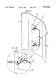
- FIG. 3 is a perspective view showing a structure of which has a choke reflector according to the present invention.
- FIG. 4 is a perspective view showing the structure of a choke reflector antenna with a snow-proof cover according to the present invention.
- FIG. 5 is a characteristic view showing horizontal radiation patterns of a vertical polarized wave of a choke reflector antenna according to the present invention.
- a coaxial dipole 1 is a half wavelength long and two supporters are vertically formed in the center of the coaxial dipole 1 to a predetermined length. Also, a fitting plate is formed in the lower end of the two supporters which are fixed to the reflector of a antenna.
- An impedance matching unit 5 attached in the center of the supporter is used for controlling impedance in response to the frequency which is now used in the antenna. That is, since a variety of elements are coupled to the coaxial dipole 1, it is necessary to control impedance variation. Then, the impedance matching unit 5 is movable in a right or left direction to match impedance.
- the coaxial dipole 1, the impedance matching unit 5, and a n-port power divider 3 are fixed to a folded reflector 2.
- Both ends of the folded reflector 2 which has influence on the characteristics of the antenna, are folded at a predetermined portion and angle in order to prevent sideward radiation.
- the two ends of the folded reflector 2 are folded to an angle of 45° ⁇ 90°, being appropriate for the characteristics of the antenna.
- the folded reflector 2 may also be a fitting type or a variable type.
- a number of the coaxial dipoles are uniformally arranged on the center of the folded reflector 2. The more coaxial dipoles there are, the more gain of the antenna that can be achieved.
- n-port power divider 3 is attached on the folded reflector 2 to provide the coaxial dipole 1 with power.
- One end of a coaxial feeder 4, having a uniform phase, is connected to the center of the coaxial dipole 1 by soldering and the other end of the coaxial feeder 4 is connected to the n-port power divider 3.
- FIG. 3 shows choke reflectors 6 and 6' attached to the folded reflector 2 in FIG. 2.
- the choke reflectors 6 and 6' are formed on a metal plate and vertically attached to a portion between the coaxial dipole 1 and the folded portion of the choke reflector 2, in order that the two sides of the coaxial dipole 1 are shielded by the choke reflectors 6 and 6'. Also, the position of the choke reflectors 6 and 6' can be movable in a horizontal direction to control the characteristics of the antenna. If necessary, several choke reflectors can be set on the folded reflector 2.
- the electric power transmitted from a transmitter is converted into radio waves and the radio waves are propagated over the air. Then, the radio waves are reflected by the choke reflector 6 and 6'. However, some of the radio waves pass through the choke reflector 6 and 6'. At this time, some of the radio waves, which pass through the choke reflector 6 and 6', are reflected over again by the folded portion of the folded reflector 2, and the rest are propagated over the air. If a number of the choke reflectors are formed on the folded reflector, the sideward radiation of the radio waves can be minimized. Also, 3 dB beamwidth, which is one of the characteristics of antenna, can be controlled by controlling the amount of the radiation in a forward direction with the choke reflector 6 and 6'. This effect can also be obtained by controlling the position of the choke reflectors 6 and 6'.
- FIG. 4 shows a snowy-proof cover 7, which protects the coaxial dipole 1, the coaxial feeder 4 and the feeding point from external conditions such as rain and snow.
- FIG. 5 shows the radiation pattern of the present invention and the radiation pattern of a conventional plane reflector antenna.
- a numeral A is the horizontal radiation pattern of the present invention and a numeral B is the horizontal radiation pattern of a conventional reflector antenna.
- pattern A is diminished in comparison with pattern B.
- -5 dB and -7 dB attenuation area are shown at 270° and 90°, respectively.
- the present invention has an effect on the antenna system in that an excellent communication quality, a sufficient insurance of a communication area, a reduction of wind pressure, according to diminution of the antenna's size, the improved characteristics of the antenna, such as the 3 dB beamwidth and the front-to-back ratio can be obtained by controlling the number of and the position of the choke reflectors.
Abstract
Description
Claims (3)
Applications Claiming Priority (2)
| Application Number | Priority Date | Filing Date | Title |
|---|---|---|---|
| KR95-4409 | 1995-03-03 | ||
| KR1019950004409A KR0185962B1 (en) | 1995-03-03 | 1995-03-03 | Antenna |
Publications (1)
| Publication Number | Publication Date |
|---|---|
| US5710569A true US5710569A (en) | 1998-01-20 |
Family
ID=19409205
Family Applications (1)
| Application Number | Title | Priority Date | Filing Date |
|---|---|---|---|
| US08/428,012 Expired - Lifetime US5710569A (en) | 1995-03-03 | 1995-04-25 | Antenna system having a choke reflector for minimizing sideward radiation |
Country Status (6)
| Country | Link |
|---|---|
| US (1) | US5710569A (en) |
| EP (1) | EP0730319B1 (en) |
| KR (1) | KR0185962B1 (en) |
| DE (1) | DE69514206T2 (en) |
| DK (1) | DK0730319T3 (en) |
| ES (1) | ES2141273T3 (en) |
Cited By (43)
| Publication number | Priority date | Publication date | Assignee | Title |
|---|---|---|---|---|
| WO1998054785A1 (en) * | 1997-05-27 | 1998-12-03 | Allen Telecom Inc. | Dual polarized aperture coupled microstrip patch antenna system |
| US5982337A (en) * | 1998-02-20 | 1999-11-09 | Marconi Aerospace Systems Inc. | Cellular antennas for stratosphere coverage of multi-band annular earth pattern |
| US6037912A (en) * | 1998-09-22 | 2000-03-14 | Allen Telecom Inc. | Low profile bi-directional antenna |
| US6114999A (en) * | 1996-11-08 | 2000-09-05 | Telefonaktiebolaget Lm Ericsson | Field controlled resonator |
| US6195063B1 (en) * | 1997-05-30 | 2001-02-27 | Kathrein-Werke Kg | Dual-polarized antenna system |
| EP1102349A2 (en) * | 1999-11-22 | 2001-05-23 | TRW Inc. | High performance, directional cellular band antenna |
| WO2002071546A1 (en) * | 2001-03-05 | 2002-09-12 | Nokia Corporation | Enhancement of the field pattern of a device for transferring electromagnetic waves |
| US20020140618A1 (en) * | 2001-03-29 | 2002-10-03 | Alcatel | Multiband telecommunication antenna |
| US6795035B2 (en) * | 2002-03-28 | 2004-09-21 | Lucent Technologies Inc. | System for antenna sidelobe modification |
| US20040201543A1 (en) * | 2003-04-11 | 2004-10-14 | Kathrein-Werke Kg. | Reflector, in particular for a mobile radio antenna |
| US20040201542A1 (en) * | 2003-04-11 | 2004-10-14 | Kathrein-Werke Kg | Reflector, in particular for a mobile radio antenna |
| US6839038B2 (en) * | 2002-06-17 | 2005-01-04 | Lockheed Martin Corporation | Dual-band directional/omnidirectional antenna |
| US6885352B2 (en) * | 2001-11-16 | 2005-04-26 | Lg Electronics Inc. | Wireless communications antenna assembly generating minimal back lobe radio frequency (RF) patterns |
| US20050134512A1 (en) * | 2003-12-18 | 2005-06-23 | Kathrein-Werke Kg, | Mobile radio antenna arrangement for a base station |
| US20050134511A1 (en) * | 2003-12-18 | 2005-06-23 | Kathrein-Werke Kg | Broadband Omnidirectional Antenna |
| US20050134517A1 (en) * | 2003-12-18 | 2005-06-23 | Kathrein-Werke Kg | Antenna having at least one dipole or an antenna element arrangement similar to a dipole |
| DE10359622A1 (en) * | 2003-12-18 | 2005-07-21 | Kathrein-Werke Kg | Antenna with at least one dipole or a dipole-like radiator arrangement |
| DE10359623A1 (en) * | 2003-12-18 | 2005-07-21 | Kathrein-Werke Kg | Mobile antenna arrangement for a base station |
| US20050190116A1 (en) * | 2004-02-27 | 2005-09-01 | Andrew Corporation | Reflector antenna radome with backlobe suppressor ring and method of manufacturing |
| US20050264463A1 (en) * | 2004-05-27 | 2005-12-01 | Kathrein-Werke Kg | Stationary mobile radio antenna |
| US20060139231A1 (en) * | 2004-12-27 | 2006-06-29 | Ntt Docomo, Inc. | Antenna that uses four metal conductors |
| EP1689022A1 (en) | 2005-02-08 | 2006-08-09 | Kathrein-Werke KG | Basestation antenna |
| US20070139278A1 (en) * | 2005-06-29 | 2007-06-21 | Peter Slattman | System and Method for Providing Antenna Radiation Pattern Control |
| US20070146225A1 (en) * | 2005-12-28 | 2007-06-28 | Kathrein-Werke Kg | Dual polarized antenna |
| DE102005061636A1 (en) * | 2005-12-22 | 2007-06-28 | Kathrein-Werke Kg | Antenna for base station of mobile radio antenna, has longitudinal and/or cross bars that are length-variable in direct or indirect manner by deviation and/or bending and/or deformation and curving |
| US20080036674A1 (en) * | 2006-08-10 | 2008-02-14 | Kathrein-Werke Kg | Antenna arrangement, in particular for a mobile radio base station |
| DE102006037518B3 (en) * | 2006-08-10 | 2008-03-06 | Kathrein-Werke Kg | Antenna arrangement, in particular for a mobile radio base station |
| DE102007006559B3 (en) * | 2007-02-09 | 2008-09-11 | Kathrein-Werke Kg | Mobile antenna, in particular for a base station |
| US20080316126A1 (en) * | 2004-12-09 | 2008-12-25 | Klaus Voigtlander | Antenna System for a Radar Transceiver |
| EP2058901A1 (en) | 2007-11-07 | 2009-05-13 | Alcatel Lucent | Reflecting-trap antenna |
| US20090121957A1 (en) * | 2005-06-30 | 2009-05-14 | Yagi Antenna Inc. | Antenna |
| US20100214190A1 (en) * | 2007-10-05 | 2010-08-26 | Ace Antenna Corporation | Antenna having a choke member |
| WO2010124787A1 (en) | 2009-04-30 | 2010-11-04 | Kathrein-Werke Kg | Method for operating a phase-controlled group antenna and a phase shifter assembly and an associated phase-controlled group antenna |
| JP2012156993A (en) * | 2010-12-30 | 2012-08-16 | Telekom Malaysia Berhad | Folded dipole antenna with 450 mhz |
| US20120280874A1 (en) * | 2009-12-21 | 2012-11-08 | In-Ho Kim | Reconfigurable base station antenna |
| CN103219590A (en) * | 2013-03-29 | 2013-07-24 | 京信通信技术(广州)有限公司 | Phase shift device capable of adjusting isolation |
| US20140184464A1 (en) * | 2011-02-28 | 2014-07-03 | Ace Technologies Corporation | Multi-array antenna |
| CN105591207A (en) * | 2014-10-21 | 2016-05-18 | 上海贝尔股份有限公司 | Antenna reflecting plate and base station antenna comprising same |
| DE102015002441A1 (en) | 2015-02-26 | 2016-09-01 | Kathrein-Werke Kg | Radome and associated mobile radio antenna and method for the production of the radome or the mobile radio antenna |
| US9837724B2 (en) | 2016-03-01 | 2017-12-05 | Wistron Neweb Corp. | Antenna system |
| TWI628862B (en) * | 2016-05-10 | 2018-07-01 | 啟碁科技股份有限公司 | Communication device |
| US10784589B2 (en) * | 2015-11-19 | 2020-09-22 | Nec Corporation | Wireless communication device |
| US11233323B2 (en) | 2019-01-18 | 2022-01-25 | Samsung Electronics Co., Ltd. | Antenna module including metal structure for reducing radio waves radiated toward back lobe and electronic device including the same |
Families Citing this family (13)
| Publication number | Priority date | Publication date | Assignee | Title |
|---|---|---|---|---|
| SE508513C2 (en) * | 1997-02-14 | 1998-10-12 | Ericsson Telefon Ab L M | Microstrip antenna as well as group antenna |
| FR2777701B1 (en) * | 1998-04-15 | 2003-07-04 | Sagem | SECTORIZED DIAGRAM ANTENNA |
| US5999145A (en) * | 1998-06-26 | 1999-12-07 | Harris Corporation | Antenna system |
| KR100269584B1 (en) * | 1998-07-06 | 2000-10-16 | 구관영 | Low sidelobe double polarization directional antenna with chalk reflector |
| FR2785488B1 (en) * | 1998-10-28 | 2000-12-22 | Fr D Engineering Et De Represe | REPEATER SYSTEM, PARTICULARLY IN THE FIELD OF MOBILE TELEPHONY |
| SE527757C2 (en) | 2004-07-28 | 2006-05-30 | Powerwave Technologies Sweden | A reflector, an antenna using a reflector and a manufacturing method for a reflector |
| US7079083B2 (en) | 2004-11-30 | 2006-07-18 | Kathrein-Werke Kg | Antenna, in particular a mobile radio antenna |
| DE102004057774B4 (en) * | 2004-11-30 | 2006-07-20 | Kathrein-Werke Kg | Mobile radio aerials for operation in several frequency bands, with several dipole radiator, in front of reflector, radiating in two different frequency bands, with specified spacing of radiator structure, radiator elements, etc |
| KR100731278B1 (en) * | 2005-01-31 | 2007-06-25 | 주식회사 와이어리스데이터커뮤니케이션 | antenna assembly |
| KR100983615B1 (en) * | 2008-08-11 | 2010-09-24 | 주식회사 에이스테크놀로지 | Choke member having step height and antenna including the same |
| EP2522051B1 (en) | 2010-01-08 | 2016-08-17 | Vestas Wind Systems A/S | Antenna beam control elements, systems, architectures, and methods for radar, communications, and other applications |
| CN105576367A (en) * | 2016-03-10 | 2016-05-11 | 西安电子科技大学 | Foldable corner reflector antenna |
| WO2018212825A1 (en) * | 2017-05-17 | 2018-11-22 | Commscope Technologies Llc | Base station antennas having reflector assemblies with rf chokes |
Citations (6)
| Publication number | Priority date | Publication date | Assignee | Title |
|---|---|---|---|---|
| GB839490A (en) * | 1957-07-24 | 1960-06-29 | Marconi Wireless Telegraph Co | Improvements in or relating to aerial systems |
| EP0045254A1 (en) * | 1980-07-29 | 1982-02-03 | Thomson-Csf | Compact dual-frequency microwave feed |
| US5111214A (en) * | 1986-10-10 | 1992-05-05 | Hazeltine Corporation | Linear array antenna with E-plane backlobe suppressor |
| US5229783A (en) * | 1991-01-02 | 1993-07-20 | Tilston Stephen E | Field adjustable sectoral antenna |
| US5440318A (en) * | 1990-08-22 | 1995-08-08 | Butland; Roger J. | Panel antenna having groups of dipoles fed with insertable delay lines for electrical beam tilting and a mechanically tiltable ground plane |
| US5469181A (en) * | 1994-03-18 | 1995-11-21 | Celwave | Variable horizontal beamwidth antenna having hingeable side reflectors |
Family Cites Families (5)
| Publication number | Priority date | Publication date | Assignee | Title |
|---|---|---|---|---|
| FR2390027A1 (en) * | 1977-05-05 | 1978-12-01 | Thomson Csf | Attenuation of slotted waveguide aerial parasitic side lobes - is achieved by plate filter installed in plane of emission |
| CA1238714A (en) * | 1984-09-03 | 1988-06-28 | Hajime Seki | Shaped beam antenna |
| ES8801066A1 (en) * | 1984-12-20 | 1987-12-01 | Marconi Co Ltd | A dipole array. |
| JP3278871B2 (en) * | 1991-09-13 | 2002-04-30 | 株式会社デンソー | Antenna device |
| JPH05291822A (en) * | 1992-04-10 | 1993-11-05 | Denki Kogyo Co Ltd | Antenna system |
-
1995
- 1995-03-03 KR KR1019950004409A patent/KR0185962B1/en not_active IP Right Cessation
- 1995-04-06 ES ES95105206T patent/ES2141273T3/en not_active Expired - Lifetime
- 1995-04-06 EP EP95105206A patent/EP0730319B1/en not_active Expired - Lifetime
- 1995-04-06 DE DE69514206T patent/DE69514206T2/en not_active Expired - Lifetime
- 1995-04-06 DK DK95105206T patent/DK0730319T3/en active
- 1995-04-25 US US08/428,012 patent/US5710569A/en not_active Expired - Lifetime
Patent Citations (6)
| Publication number | Priority date | Publication date | Assignee | Title |
|---|---|---|---|---|
| GB839490A (en) * | 1957-07-24 | 1960-06-29 | Marconi Wireless Telegraph Co | Improvements in or relating to aerial systems |
| EP0045254A1 (en) * | 1980-07-29 | 1982-02-03 | Thomson-Csf | Compact dual-frequency microwave feed |
| US5111214A (en) * | 1986-10-10 | 1992-05-05 | Hazeltine Corporation | Linear array antenna with E-plane backlobe suppressor |
| US5440318A (en) * | 1990-08-22 | 1995-08-08 | Butland; Roger J. | Panel antenna having groups of dipoles fed with insertable delay lines for electrical beam tilting and a mechanically tiltable ground plane |
| US5229783A (en) * | 1991-01-02 | 1993-07-20 | Tilston Stephen E | Field adjustable sectoral antenna |
| US5469181A (en) * | 1994-03-18 | 1995-11-21 | Celwave | Variable horizontal beamwidth antenna having hingeable side reflectors |
Cited By (81)
| Publication number | Priority date | Publication date | Assignee | Title |
|---|---|---|---|---|
| US6114999A (en) * | 1996-11-08 | 2000-09-05 | Telefonaktiebolaget Lm Ericsson | Field controlled resonator |
| WO1998054785A1 (en) * | 1997-05-27 | 1998-12-03 | Allen Telecom Inc. | Dual polarized aperture coupled microstrip patch antenna system |
| US5896107A (en) * | 1997-05-27 | 1999-04-20 | Allen Telecom Inc. | Dual polarized aperture coupled microstrip patch antenna system |
| US6195063B1 (en) * | 1997-05-30 | 2001-02-27 | Kathrein-Werke Kg | Dual-polarized antenna system |
| US5982337A (en) * | 1998-02-20 | 1999-11-09 | Marconi Aerospace Systems Inc. | Cellular antennas for stratosphere coverage of multi-band annular earth pattern |
| US6037912A (en) * | 1998-09-22 | 2000-03-14 | Allen Telecom Inc. | Low profile bi-directional antenna |
| EP1102349A3 (en) * | 1999-11-22 | 2004-03-17 | Northrop Grumman Corporation | High performance, directional cellular band antenna |
| US6281858B1 (en) * | 1999-11-22 | 2001-08-28 | Trw Inc. | High performance, directional cellular band antenna |
| EP1102349A2 (en) * | 1999-11-22 | 2001-05-23 | TRW Inc. | High performance, directional cellular band antenna |
| WO2002071546A1 (en) * | 2001-03-05 | 2002-09-12 | Nokia Corporation | Enhancement of the field pattern of a device for transferring electromagnetic waves |
| US20040046696A1 (en) * | 2001-03-05 | 2004-03-11 | Risto Martikkala | Enhancement of the field pattern of a device for transferring electromagnetic waves |
| US6828945B2 (en) | 2001-03-05 | 2004-12-07 | Nokia Corporation | Enhancement of the field pattern of a device for transferring electromagnetic waves |
| US20020140618A1 (en) * | 2001-03-29 | 2002-10-03 | Alcatel | Multiband telecommunication antenna |
| US6646611B2 (en) * | 2001-03-29 | 2003-11-11 | Alcatel | Multiband telecommunication antenna |
| US6885352B2 (en) * | 2001-11-16 | 2005-04-26 | Lg Electronics Inc. | Wireless communications antenna assembly generating minimal back lobe radio frequency (RF) patterns |
| DE10217330B4 (en) * | 2001-11-16 | 2013-04-11 | Lg Electronics Inc. | Wireless communication antenna assembly for generating radio frequency (RF) pattern with minimum reverse lobe |
| US6795035B2 (en) * | 2002-03-28 | 2004-09-21 | Lucent Technologies Inc. | System for antenna sidelobe modification |
| US6839038B2 (en) * | 2002-06-17 | 2005-01-04 | Lockheed Martin Corporation | Dual-band directional/omnidirectional antenna |
| US6930651B2 (en) | 2003-04-11 | 2005-08-16 | Kathrein-Werke Kg | Reflector for a mobile radio antenna |
| US20040201542A1 (en) * | 2003-04-11 | 2004-10-14 | Kathrein-Werke Kg | Reflector, in particular for a mobile radio antenna |
| US20040201543A1 (en) * | 2003-04-11 | 2004-10-14 | Kathrein-Werke Kg. | Reflector, in particular for a mobile radio antenna |
| US7023398B2 (en) | 2003-04-11 | 2006-04-04 | Kathrein-Werke Kg | Reflector for a mobile radio antenna |
| US7015871B2 (en) | 2003-12-18 | 2006-03-21 | Kathrein-Werke Kg | Mobile radio antenna arrangement for a base station |
| US20050134512A1 (en) * | 2003-12-18 | 2005-06-23 | Kathrein-Werke Kg, | Mobile radio antenna arrangement for a base station |
| US7132995B2 (en) | 2003-12-18 | 2006-11-07 | Kathrein-Werke Kg | Antenna having at least one dipole or an antenna element arrangement similar to a dipole |
| DE10359623A1 (en) * | 2003-12-18 | 2005-07-21 | Kathrein-Werke Kg | Mobile antenna arrangement for a base station |
| DE10359622A1 (en) * | 2003-12-18 | 2005-07-21 | Kathrein-Werke Kg | Antenna with at least one dipole or a dipole-like radiator arrangement |
| US20050134517A1 (en) * | 2003-12-18 | 2005-06-23 | Kathrein-Werke Kg | Antenna having at least one dipole or an antenna element arrangement similar to a dipole |
| US7027004B2 (en) | 2003-12-18 | 2006-04-11 | Kathrein-Werke Kg | Omnidirectional broadband antenna |
| US20050134511A1 (en) * | 2003-12-18 | 2005-06-23 | Kathrein-Werke Kg | Broadband Omnidirectional Antenna |
| US20050190116A1 (en) * | 2004-02-27 | 2005-09-01 | Andrew Corporation | Reflector antenna radome with backlobe suppressor ring and method of manufacturing |
| US20050264463A1 (en) * | 2004-05-27 | 2005-12-01 | Kathrein-Werke Kg | Stationary mobile radio antenna |
| US7075498B2 (en) | 2004-05-27 | 2006-07-11 | Kathrein-Werke Kg | Stationary mobile radio antenna |
| DE102004025904B4 (en) * | 2004-05-27 | 2007-04-05 | Kathrein-Werke Kg | antenna |
| US20080316126A1 (en) * | 2004-12-09 | 2008-12-25 | Klaus Voigtlander | Antenna System for a Radar Transceiver |
| CN1797853B (en) * | 2004-12-27 | 2010-05-12 | 株式会社Ntt都科摩 | Antenna that uses four metal conductors |
| US20060139231A1 (en) * | 2004-12-27 | 2006-06-29 | Ntt Docomo, Inc. | Antenna that uses four metal conductors |
| US7218288B2 (en) * | 2004-12-27 | 2007-05-15 | Ntt Docomo, Inc. | Antenna that uses four metal conductors |
| DE102005005781A1 (en) * | 2005-02-08 | 2006-08-10 | Kathrein-Werke Kg | Radom, in particular for mobile radio antennas and associated mobile radio antenna |
| US20060176235A1 (en) * | 2005-02-08 | 2006-08-10 | Kathrein-Werke Kg | Radome, in particular for mobile radio antennas, as well as an associated mobile radio antenna |
| US7245267B2 (en) | 2005-02-08 | 2007-07-17 | Kathrein-Werke Kg | Mobile radio antenna radome with integral reflector |
| EP1689022A1 (en) | 2005-02-08 | 2006-08-09 | Kathrein-Werke KG | Basestation antenna |
| US20070139278A1 (en) * | 2005-06-29 | 2007-06-21 | Peter Slattman | System and Method for Providing Antenna Radiation Pattern Control |
| US7701409B2 (en) * | 2005-06-29 | 2010-04-20 | Cushcraft Corporation | System and method for providing antenna radiation pattern control |
| US8094084B2 (en) | 2005-06-30 | 2012-01-10 | Yagi Antenna Inc. | Omnidirectional antenna for indoor and outdoor use |
| US8018391B2 (en) | 2005-06-30 | 2011-09-13 | Yagi Antenna Inc. | Plate-shaped antenna having at least three planes |
| US20100090919A1 (en) * | 2005-06-30 | 2010-04-15 | Yagi Antenna Inc. | Antenna |
| US20090121957A1 (en) * | 2005-06-30 | 2009-05-14 | Yagi Antenna Inc. | Antenna |
| WO2007076963A1 (en) | 2005-12-22 | 2007-07-12 | Kathrein-Werke Kg | Dual-polarized antenna having longitudinal or transverse webs |
| DE102005061636A1 (en) * | 2005-12-22 | 2007-06-28 | Kathrein-Werke Kg | Antenna for base station of mobile radio antenna, has longitudinal and/or cross bars that are length-variable in direct or indirect manner by deviation and/or bending and/or deformation and curving |
| CN101160692B (en) * | 2005-12-22 | 2013-01-02 | 凯瑟雷恩工厂两合公司 | Dual-polarized antenna having longitudinal or transverse webs |
| US20070146225A1 (en) * | 2005-12-28 | 2007-06-28 | Kathrein-Werke Kg | Dual polarized antenna |
| US7427966B2 (en) | 2005-12-28 | 2008-09-23 | Kathrein-Werke Kg | Dual polarized antenna |
| US7679576B2 (en) | 2006-08-10 | 2010-03-16 | Kathrein-Werke Kg | Antenna arrangement, in particular for a mobile radio base station |
| DE102006037518B3 (en) * | 2006-08-10 | 2008-03-06 | Kathrein-Werke Kg | Antenna arrangement, in particular for a mobile radio base station |
| US20100182213A1 (en) * | 2006-08-10 | 2010-07-22 | Kathrein-Werke Ag | ANTENNA ARRANGEMENT FOR A MOBILE RADIO BASE STATION (As amended) |
| US20080036674A1 (en) * | 2006-08-10 | 2008-02-14 | Kathrein-Werke Kg | Antenna arrangement, in particular for a mobile radio base station |
| US8350775B2 (en) | 2006-08-10 | 2013-01-08 | Kathrein-Werke Kg | Antenna arrangement for a mobile radio base station |
| DE102007006559B3 (en) * | 2007-02-09 | 2008-09-11 | Kathrein-Werke Kg | Mobile antenna, in particular for a base station |
| US20100214190A1 (en) * | 2007-10-05 | 2010-08-26 | Ace Antenna Corporation | Antenna having a choke member |
| US8860622B2 (en) * | 2007-10-05 | 2014-10-14 | Ace Antenna Corporation | Antenna having a choke member |
| EP2058901A1 (en) | 2007-11-07 | 2009-05-13 | Alcatel Lucent | Reflecting-trap antenna |
| US9160062B2 (en) | 2009-04-30 | 2015-10-13 | Kathrein-Werke Kg | Method for operating a phase-controlled group antenna and phase shifter assembly and an associated phase-controlled group antenna |
| DE102009019557A1 (en) | 2009-04-30 | 2010-11-11 | Kathrein-Werke Kg | A method of operating a phased array antenna and a phase shifter assembly and associated phased array antenna |
| WO2010124787A1 (en) | 2009-04-30 | 2010-11-04 | Kathrein-Werke Kg | Method for operating a phase-controlled group antenna and a phase shifter assembly and an associated phase-controlled group antenna |
| US20120280874A1 (en) * | 2009-12-21 | 2012-11-08 | In-Ho Kim | Reconfigurable base station antenna |
| US8743008B2 (en) * | 2009-12-21 | 2014-06-03 | Kmw Inc. | Reconfigurable base station antenna |
| JP2012156993A (en) * | 2010-12-30 | 2012-08-16 | Telekom Malaysia Berhad | Folded dipole antenna with 450 mhz |
| US20140184464A1 (en) * | 2011-02-28 | 2014-07-03 | Ace Technologies Corporation | Multi-array antenna |
| US9368877B2 (en) * | 2011-02-28 | 2016-06-14 | Ace Technologies Corporation | Multi-array antenna |
| CN103219590A (en) * | 2013-03-29 | 2013-07-24 | 京信通信技术(广州)有限公司 | Phase shift device capable of adjusting isolation |
| CN103219590B (en) * | 2013-03-29 | 2015-07-15 | 京信通信技术(广州)有限公司 | Phase shift device capable of adjusting isolation |
| CN105591207A (en) * | 2014-10-21 | 2016-05-18 | 上海贝尔股份有限公司 | Antenna reflecting plate and base station antenna comprising same |
| CN105591207B (en) * | 2014-10-21 | 2019-03-12 | 上海诺基亚贝尔股份有限公司 | Antenna-reflected plate and antenna for base station including the antenna-reflected plate |
| DE102015002441A1 (en) | 2015-02-26 | 2016-09-01 | Kathrein-Werke Kg | Radome and associated mobile radio antenna and method for the production of the radome or the mobile radio antenna |
| WO2016135080A1 (en) | 2015-02-26 | 2016-09-01 | Kathrein-Werke Kg | Radome and associated mobile communications antenna, and method for producing the radome or the mobile communications antenna |
| US10879602B2 (en) | 2015-02-26 | 2020-12-29 | Telefonaktiebolaget Lm Ericsson (Publ) | Radome and associated mobile communications antenna, and method for producing the radome or the mobile communications antenna |
| US10784589B2 (en) * | 2015-11-19 | 2020-09-22 | Nec Corporation | Wireless communication device |
| US9837724B2 (en) | 2016-03-01 | 2017-12-05 | Wistron Neweb Corp. | Antenna system |
| TWI628862B (en) * | 2016-05-10 | 2018-07-01 | 啟碁科技股份有限公司 | Communication device |
| US11233323B2 (en) | 2019-01-18 | 2022-01-25 | Samsung Electronics Co., Ltd. | Antenna module including metal structure for reducing radio waves radiated toward back lobe and electronic device including the same |
Also Published As
| Publication number | Publication date |
|---|---|
| EP0730319B1 (en) | 1999-12-29 |
| ES2141273T3 (en) | 2000-03-16 |
| DK0730319T3 (en) | 2000-06-19 |
| DE69514206D1 (en) | 2000-02-03 |
| KR0185962B1 (en) | 1999-05-15 |
| DE69514206T2 (en) | 2000-07-13 |
| EP0730319A1 (en) | 1996-09-04 |
| KR960036199A (en) | 1996-10-28 |
Similar Documents
| Publication | Publication Date | Title |
|---|---|---|
| US5710569A (en) | Antenna system having a choke reflector for minimizing sideward radiation | |
| US6140972A (en) | Multiport antenna | |
| EP0960452B1 (en) | Microstrip antenna and array antenna | |
| US6967618B2 (en) | Antenna with variable directional pattern | |
| EP0444679B1 (en) | Mobile antenna | |
| US6094177A (en) | Planar radiation antenna elements and omni directional antenna using such antenna elements | |
| US5185611A (en) | Compact antenna array for diversity applications | |
| US11652300B2 (en) | Radiating elements having angled feed stalks and base station antennas including same | |
| CN101026267A (en) | Dual band phased array employing spatial second harmonics | |
| US20200244327A1 (en) | Spherical coverage antenna systems, devices, and methods | |
| US5600337A (en) | Y-antenna | |
| US20220353699A1 (en) | Base station antennas with sector splitting in the elevation plane based on frequency band | |
| EP0588271B1 (en) | Portable transceiver apparatus with low irradiation of the user, employing an antenna having an asymmetric radiation pattern | |
| US3696437A (en) | Broadside log periodic antenna | |
| JPH07202562A (en) | Printed dipole antenna | |
| US5977926A (en) | Multi-focus reflector antenna | |
| US20230092632A1 (en) | Antenna apparatus and radio communications device | |
| US4737796A (en) | Ground plane interference elimination by passive element | |
| JPH0669716A (en) | Wide band-two dipole antenna | |
| KR102045483B1 (en) | Terminal Antenna for Millimeter Wave | |
| US20050285810A1 (en) | Directional dual frequency antenna arrangement | |
| JP3057173B2 (en) | Corner reflector antenna device | |
| JPH11355031A (en) | Antenna | |
| KR100562227B1 (en) | Method and Apparatus for Adjusting Tilting Angles of Broadband Array Antenna | |
| JPH08102612A (en) | Directional antenna |
Legal Events
| Date | Code | Title | Description |
|---|---|---|---|
| AS | Assignment |
Owner name: ACE ANTENNA CORPORATION, KOREA, REPUBLIC OF Free format text: ASSIGNMENT OF ASSIGNORS INTEREST;ASSIGNORS:OH, JUNG KUN;LEE, YONG HEE;LEE, JAE HO;AND OTHERS;REEL/FRAME:007538/0770 Effective date: 19950322 |
|
| STCF | Information on status: patent grant |
Free format text: PATENTED CASE |
|
| FEPP | Fee payment procedure |
Free format text: PAYOR NUMBER ASSIGNED (ORIGINAL EVENT CODE: ASPN); ENTITY STATUS OF PATENT OWNER: SMALL ENTITY |
|
| FPAY | Fee payment |
Year of fee payment: 4 |
|
| FEPP | Fee payment procedure |
Free format text: PAT HOLDER NO LONGER CLAIMS SMALL ENTITY STATUS, ENTITY STATUS SET TO UNDISCOUNTED (ORIGINAL EVENT CODE: STOL); ENTITY STATUS OF PATENT OWNER: SMALL ENTITY |
|
| REFU | Refund |
Free format text: REFUND - PAYMENT OF MAINTENANCE FEE, 8TH YR, SMALL ENTITY (ORIGINAL EVENT CODE: R2552); ENTITY STATUS OF PATENT OWNER: SMALL ENTITY |
|
| FPAY | Fee payment |
Year of fee payment: 8 |
|
| FEPP | Fee payment procedure |
Free format text: PAT HOLDER CLAIMS SMALL ENTITY STATUS, ENTITY STATUS SET TO SMALL (ORIGINAL EVENT CODE: LTOS); ENTITY STATUS OF PATENT OWNER: SMALL ENTITY |
|
| FPAY | Fee payment |
Year of fee payment: 12 |
|
| AS | Assignment |
Owner name: HEO, JAE HYUNG, KOREA, REPUBLIC OF Free format text: ASSIGNMENT OF ASSIGNORS INTEREST;ASSIGNOR:ACE ANTENNA CORPORATION;REEL/FRAME:033986/0895 Effective date: 20141017 |
|
| AS | Assignment |
Owner name: CASCADE IP CONSULTING, LLC, WASHINGTON Free format text: ASSIGNMENT OF ASSIGNORS INTEREST;ASSIGNOR:HEO, JAE HYUNG;REEL/FRAME:034021/0430 Effective date: 20141022 |