US5729474A - Method of anticipating potential HVAC failure - Google Patents
Method of anticipating potential HVAC failure Download PDFInfo
- Publication number
- US5729474A US5729474A US08/353,536 US35353694A US5729474A US 5729474 A US5729474 A US 5729474A US 35353694 A US35353694 A US 35353694A US 5729474 A US5729474 A US 5729474A
- Authority
- US
- United States
- Prior art keywords
- temperature
- modification device
- value
- zone
- sub
- Prior art date
- Legal status (The legal status is an assumption and is not a legal conclusion. Google has not performed a legal analysis and makes no representation as to the accuracy of the status listed.)
- Expired - Lifetime
Links
Images


Classifications
-
- G—PHYSICS
- G05—CONTROLLING; REGULATING
- G05D—SYSTEMS FOR CONTROLLING OR REGULATING NON-ELECTRIC VARIABLES
- G05D23/00—Control of temperature
- G05D23/19—Control of temperature characterised by the use of electric means
- G05D23/1917—Control of temperature characterised by the use of electric means using digital means
-
- F—MECHANICAL ENGINEERING; LIGHTING; HEATING; WEAPONS; BLASTING
- F24—HEATING; RANGES; VENTILATING
- F24F—AIR-CONDITIONING; AIR-HUMIDIFICATION; VENTILATION; USE OF AIR CURRENTS FOR SCREENING
- F24F11/00—Control or safety arrangements
-
- F—MECHANICAL ENGINEERING; LIGHTING; HEATING; WEAPONS; BLASTING
- F24—HEATING; RANGES; VENTILATING
- F24F—AIR-CONDITIONING; AIR-HUMIDIFICATION; VENTILATION; USE OF AIR CURRENTS FOR SCREENING
- F24F11/00—Control or safety arrangements
- F24F11/30—Control or safety arrangements for purposes related to the operation of the system, e.g. for safety or monitoring
- F24F11/32—Responding to malfunctions or emergencies
- F24F11/38—Failure diagnosis
-
- F—MECHANICAL ENGINEERING; LIGHTING; HEATING; WEAPONS; BLASTING
- F24—HEATING; RANGES; VENTILATING
- F24F—AIR-CONDITIONING; AIR-HUMIDIFICATION; VENTILATION; USE OF AIR CURRENTS FOR SCREENING
- F24F11/00—Control or safety arrangements
- F24F11/30—Control or safety arrangements for purposes related to the operation of the system, e.g. for safety or monitoring
- F24F11/46—Improving electric energy efficiency or saving
-
- F—MECHANICAL ENGINEERING; LIGHTING; HEATING; WEAPONS; BLASTING
- F24—HEATING; RANGES; VENTILATING
- F24F—AIR-CONDITIONING; AIR-HUMIDIFICATION; VENTILATION; USE OF AIR CURRENTS FOR SCREENING
- F24F11/00—Control or safety arrangements
- F24F11/50—Control or safety arrangements characterised by user interfaces or communication
- F24F11/56—Remote control
-
- F—MECHANICAL ENGINEERING; LIGHTING; HEATING; WEAPONS; BLASTING
- F24—HEATING; RANGES; VENTILATING
- F24F—AIR-CONDITIONING; AIR-HUMIDIFICATION; VENTILATION; USE OF AIR CURRENTS FOR SCREENING
- F24F11/00—Control or safety arrangements
- F24F11/62—Control or safety arrangements characterised by the type of control or by internal processing, e.g. using fuzzy logic, adaptive control or estimation of values
- F24F11/63—Electronic processing
- F24F11/64—Electronic processing using pre-stored data
-
- F—MECHANICAL ENGINEERING; LIGHTING; HEATING; WEAPONS; BLASTING
- F24—HEATING; RANGES; VENTILATING
- F24F—AIR-CONDITIONING; AIR-HUMIDIFICATION; VENTILATION; USE OF AIR CURRENTS FOR SCREENING
- F24F11/00—Control or safety arrangements
- F24F11/88—Electrical aspects, e.g. circuits
-
- F—MECHANICAL ENGINEERING; LIGHTING; HEATING; WEAPONS; BLASTING
- F24—HEATING; RANGES; VENTILATING
- F24F—AIR-CONDITIONING; AIR-HUMIDIFICATION; VENTILATION; USE OF AIR CURRENTS FOR SCREENING
- F24F11/00—Control or safety arrangements
- F24F11/30—Control or safety arrangements for purposes related to the operation of the system, e.g. for safety or monitoring
- F24F11/32—Responding to malfunctions or emergencies
-
- F—MECHANICAL ENGINEERING; LIGHTING; HEATING; WEAPONS; BLASTING
- F24—HEATING; RANGES; VENTILATING
- F24F—AIR-CONDITIONING; AIR-HUMIDIFICATION; VENTILATION; USE OF AIR CURRENTS FOR SCREENING
- F24F11/00—Control or safety arrangements
- F24F11/50—Control or safety arrangements characterised by user interfaces or communication
- F24F11/52—Indication arrangements, e.g. displays
-
- F—MECHANICAL ENGINEERING; LIGHTING; HEATING; WEAPONS; BLASTING
- F24—HEATING; RANGES; VENTILATING
- F24F—AIR-CONDITIONING; AIR-HUMIDIFICATION; VENTILATION; USE OF AIR CURRENTS FOR SCREENING
- F24F2110/00—Control inputs relating to air properties
- F24F2110/10—Temperature
-
- F—MECHANICAL ENGINEERING; LIGHTING; HEATING; WEAPONS; BLASTING
- F24—HEATING; RANGES; VENTILATING
- F24F—AIR-CONDITIONING; AIR-HUMIDIFICATION; VENTILATION; USE OF AIR CURRENTS FOR SCREENING
- F24F2110/00—Control inputs relating to air properties
- F24F2110/10—Temperature
- F24F2110/12—Temperature of the outside air
Definitions
- HVAC heating, ventilating and air conditioning
- An HVAC system can be controlled by various types of energy management apparatus.
- an electromechanical thermostat controls a heater gas valve or an air conditioner compressor (depending on the selected mode) and a fan.
- a microprocessor-based controller operates the HVAC equipment.
- HVAC equipment is typically operated until a failure occurs, then it is repaired. This can be costly not only because of the repair needed for the HVAC system, but also because of possible consequential costs which may result from the HVAC failure (e.g., damage to other equipment, such as computers, due to loss of cooling; overtime for repair services if failure occurs other than during normal business hours).
- preventive maintenance is performed on the equipment; however, such maintenance is typically based on a selected time period (e.g., monthly, semi-annually, annually) or on the operational time of the equipment. Such maintenance is not, to our knowledge, based on an operating characteristic of the equipment itself (other than mere time of use). Thus, conventional preventive maintenance may not detect or solve an incipient problem, and it will not prevent a failure that arises wholly between maintenance episodes.
- the present invention overcomes the above-noted and other shortcomings of the prior art by providing a novel and improved method of anticipating potential failure of a temperature modification device.
- the preferred embodiment of the present invention is designed to monitor the operation and the effectiveness (efficiency) of an HVAC system. From this, potential problems with HVAC equipment can be anticipated before they actually occur. Corrective maintenance initiating signals can then be generated before equipment is damaged.
- Steps of the method can be performed at any desired frequency. For example, monitoring can occur each morning when the HVAC system is operated to bring the temperature for a controlled zone from its more energy conserving nighttime level to its more comfortable daytime level.
- the preferred embodiment of the present invention employs the following parameters: 1) outside ambient temperature(T out ), 2) inside starting temperature (T start ), 3) desired temperature setpoint (T aim ), 4) HVAC recovery time to change inside temperature from T start to T aim , and 5) the best or most efficient performance of the HVAC system to date.
- the method uses these parameters to determine the heating or cooling rate based on the temperature differential between the starting temperature (T start ) and the desired temperature setpoint (T aim ) and the corresponding recovery time to go from the starting temperature to the setpoint temperature. The method then logs this heating or cooling rate relative to the outside ambient temperature.
- one or more signals for initiating corrective action are generated.
- Data can be collected and plotted over a period of time and made available for display or hard copy printout. Historical readings can be made on a periodic basis.
- the present invention can be defined as a method of anticipating potential failure within an HVAC system operated by a digital computer to heat or cool a zone. This method comprises energizing the HVAC system to provide a selected one of heated air or cooled air to the zone.
- This energizing step includes: storing in the digital computer a value, T aim , for a desired temperature setpoint; storing in the digital computer a value, T start , of an actual temperature in the zone; determining a difference between the stored desired temperature setpoint value and the stored actual temperature value and determining whether the difference indicates the need for the selected one of heated air or cooled air; and generating a control signal for energizing the HVAC system in response to the difference indicating the need for the selected one of heated air or cooled air so that heated air or cooled air is provided to the zone for changing the temperature in the zone from T start to T aim .
- the method also comprises the step of determining whether the efficiency of the HVAC system changes over time; this includes performing the following steps contemporaneously at least once during each of a plurality of predetermined periods of time during which the step of energizing is repeatedly performed. These steps include: determining the amount of time, ⁇ t, it takes for the energized HVAC system to change the actual temperature in the zone from the respective T start to the respective T aim ; computing an efficiency value, ⁇ t/
- the present computed efficiency value exceeding the compared prior computed efficiency value represents a decrease in efficiency of the HVAC system, whereas the prior computed efficiency value exceeding the
- This method of the present invention further comprises the step of storing the present computed efficiency value in the digital computer in place of the prior computed efficiency value for the same value of T out in response to the step of comparing indicating an increase in efficiency.
- This method still further comprises generating and transmitting from the digital computer a control signal for initiating inspection of the HVAC system in response to the step of comparing indicating a decrease in efficiency exceeding a predetermined tolerance.
- the invention can be more broadly defined as a method of anticipating potential failure of a temperature modification device, comprising steps of: repeatedly computing a value for a parameter representing the ability of a temperature modification device to change temperature in a predetermined zone; determining if the ability of the temperature modification device to change temperature in the predetermined zone deteriorates over time, including comparing a current value with a previous value; and communicating a control signal for initiating inspection of the temperature modification device in response to a determined deterioration exceeding a predetermined tolerance.
- a significant advantage of the present invention is that it can be used to anticipate potential HVAC failures, thereby preventing or reducing the likelihood of inopportune down time and more serious damage to equipment.
- FIG. 1 is a block diagram of a system for performing the method of the present invention.
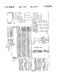
- FIGS. 2A-2R are schematic circuit diagrams for a specific implementation of the system represented in FIG. 1.
- FIG. 3 is a flow diagram of a program for programing the illustrated system to perform the method of the present invention.
- the preferred embodiment implementation of the present invention uses an energy management apparatus 2.
- the preferred embodiment of this includes a microprocessor 4.
- the microprocessor 4 operates under a timing signal provided by a timing circuit 6 which includes a crystal oscillator.
- the microprocessor 4 has address, data and control buses connected to peripherals which include a display 8 and memory 10.
- the memory 10 can be embodied in various and multiple forms (e.g., read only memory can be used to retain operating programs and predetermined values and random access memory can provide transitory working memory space).
- the foregoing elements can be implemented by any suitable devices well-known in the art.
- the preferred embodiment uses information stored in memory 10. This includes a desired temperature value, T aim , for each zone whose temperature is to be controlled by the energy management apparatus 2. This information also includes a table of efficiency values which are calculated and stored during performance of the method as subsequently described. A historical log can be created and maintained in memory 10 by the present invention.
- HVAC heating, ventilating and air conditioning
- the HVAC system 12 includes a heating subsystem 14 (including, for example, a gas heater) and a cooling subsystem 16 (including, for example, an air conditioner compressor) which typically share a common fan of the HVAC system 12.
- the fluid e.g., air or water
- zone 18 one of which is represented in FIG. 1 as zone 18.
- zone temperature sensor 20 located inside the zone 18. This is a conventional sensor, such as a National Semiconductor LM234Z-3, in the preferred embodiment.
- Another characteristic or parameter important to the preferred embodiment of the present invention is temperature outside the zone 18. This is monitored by a conventional temperature sensor 22 (e.g., National Semiconductor LM234Z-3) located outside the zone 18 to measure the ambient temperature adjacent the zone 18.
- a conventional temperature sensor 22 e.g., National Semiconductor LM234Z-3 located outside the zone 18 to measure the ambient temperature adjacent the zone 18.
- FIG. 1 shows that remote communications can be conducted with the energy management apparatus 2.
- a remote communication system 24 can be implemented in any suitable manner, such as by a modem link to which a personal computer is connected at the remote end. Bidirectional communications can occur so that information can be transferred either to or from the energy management apparatus 2.
- Other communication systems can also be used (e.g., a paging data receiver system as disclosed in the aforementioned copending United States patent application entitled “Energy Utilization Controller and Control System and Method” incorporated herein by reference).
- the energy management apparatus 2 can be an Excel Energy Technologies, Ltd. XLT-8000 energy management apparatus and the temperature sensors can be implemented by the aforementioned specific devices.
- FIGS. 2A-2R A schematic circuit diagram of relevant features of these embodiments is shown in FIGS. 2A-2R. Elements in FIGS. 2A-2R corresponding to those shown in FIG. 1 are identified by like reference numerals.
- FIGS. 2A-2M show the main processing circuits and FIGS. 2N-2R show the HVAC interface circuits.
- the HVAC system 12 it can be implemented for example by an existing system in a building where the energy management apparatus 2 and the temperature sensors are, or are to be, installed.
- the building if it is a commercial building, is typically defined, for purposes of heating and cooling, as one or more of the zones 18 (e.g., peripheral zones having windows and interior zones such as hallways).
- the equipment described above with reference to FIGS. 1 and 2 is used to perform the method of the present invention.
- This method is used for anticipating potential failure of a temperature modification device (such as the equipment of the HVAC system 12), preferably operated by a digital computer (such as implemented in the energy management apparatus 2) to heat or cool a zone (such as the zone 18 and additional zones if desired).
- a temperature modification device such as the equipment of the HVAC system 12
- a digital computer such as implemented in the energy management apparatus 2
- the HVAC system 12 is energized in conventional manner to provide a selected one of heated air or cooled air for the respective zone 18.
- the setpoint temperature is referred to herein as T aim .
- T aim a value for a desired temperature setpoint.
- Such a setpoint is defined for each zone 18 wherein temperature control is to be effected.
- This or these setpoints can be preloaded into memory 10 or changed therein via operator control through locally or remotely initiated commands applied to the energy management apparatus 2 in known manner (e.g., through keypad entry or remote link for an XLT-8000 apparatus).
- Energizing the HVAC system 12 in the preferred embodiment also includes storing in the digital computer a value of an actual temperature in the zone. This is performed by monitoring and processing the output of the temperature sensor 20, which can be performed in a conventional manner, within the energy management apparatus 2 and storing the value in memory 10.
- Energizing the HVAC system 12 further includes determining a difference between the stored desired temperature setpoint value and the stored actual temperature value. It also includes determining whether the difference indicates the need for the selected one of heated air or cooled air. This occurs, of course, if the actual zone temperature is below T aim during a selected heating mode or if the actual zone temperature is above T aim during a selected cooling mode. This is performed using known computational and comparison techniques within the digital computer.
- Energizing the HVAC system 12 still further includes generating a control signal for energizing the HVAC system in response to the computed difference indicating the need for the selected one of heated air or cooled air.
- This signal is generated in the illustrated embodiment by the microprocessor 4 and output to the HVAC system 12 (in the particular implementation of FIG. 2, the signal interconnection is made via interfaces U5 and U142 and the 2 by 8 header connectors H9 and H10 in FIG. 2L and H1 in FIG. 2N to operate the triac circuits of FIGS. 2O-2R connected to the HVAC system 12). This is performed in known manner.
- the foregoing steps are typically performed several times during various time periods. For example, each day the energy management system 2 will activate the HVAC system 12 as a monitored zone temperature drifts from the respective desired setpoint T aim . During each such period of time the present invention determines whether the efficiency of the HVAC equipment changes over time. It is through this efficiency determination that incipient problems with the HVAC system 12 can be detected and corrected whereby total failure and possible consequential damage can be avoided.
- the efficiency determination is made in the preferred embodiment of the present invention by performing the following steps contemporaneously at least once during each of a plurality of periods of time during which the above-described step of energizing is repeatedly performed (e.g., predetermined time periods such as daily, weekly, monthly, etc.).
- a preferred time is in the morning in conjunction with bringing a controlled zone's temperature back to a desired daytime level from a lower or higher nighttime level (which levels are set by changing the operative T aim ).
- At least one ambient condition is sensed.
- Each such ambient condition is preferably one that affects the rate at which the temperature modification device of the HVAC system 12 can change the controlled temperature.
- one such condition is the ambient temperature sensed by the temperature sensor 22 outside the zone 18 (e.g., the air temperature outside the building in which the zone 18 is defined).
- the digital value derived in conventional manner by the energy management apparatus 2 from the sensor 22 is stored in memory 10 in the digital computer. This value is referred to herein as T out .
- ambient temperature such as outside a building containing the zone 18, affects the rate at which temperature changes within the zone 18 during activation of the HVAC system 12 (e.g., the hotter it is outside, the longer it takes to cool inside per degree of inside temperature change).
- the efficiency determination also uses the sensed temperature for the zone 18. This can be obtained from the aforementioned sensing of this condition, or a separate reading of the sensor 20 can be used.
- the particular sensed value used is referred to herein as T start .
- each efficiency determination is made with regard to the particular T out obtained at the time of making the determination. This is so that comparisons can be made as to determinations made at different times but under the same external condition(s) (only the T out condition is used in the preferred embodiment, but it is contemplated that other or additional conditions can be used for defining the external environment within which the efficiency determination is made).
- the efficiency determination further includes determining an actual rate at which the temperature modification device changes the sensed temperature in the zone 18 from a first temperature value to a second temperature value. More specifically, the amount of time, ⁇ t, it takes for the energized HVAC system 12 to change the actual temperature in the zone 18 from the respective T start to the respective T aim is determined.
- K c (Tout) computed cooling rate used as the efficiency value for the sensed outside ambient temperature T out (minutes/° F.)
- T start starting zone temperature from which temperature change commences (° F.)
- T aim desired temperature setpoint to which temperature is to be changed (° F.)
- K h (Tout) computed heating rate used as the efficiency value for the sensed outside ambient temperature T out (minutes/° F.)
- T start starting zone temperature from which temperature change commences (° F.)
- T aim desired temperature setpoint to which temperature is to be changed (° F.)
- CR h heating recovery time in going from actual T start to actual sensed temperature equal to T aim (minutes).
- a first efficiency value After a first efficiency value has been calculated, it is stored in the table of efficiency values retained in memory 10. The value is stored in correspondence with the value of the sensed at least one ambient condition. That is, in the preferred embodiment the table is indexed by T out so that the calculated efficiency value is stored at the index corresponding to the actually sensed T out .
- the present computed efficiency value is compared with a prior computed efficiency value which was computed contemporaneously with sensing ambient temperature (in the preferred embodiment) outside the zone at the same value of T out and which was stored in the digital computer in relation to a marker identifying such same value of T out . If the present computed efficiency value exceeds the prior computed efficiency value (i.e., the present value indicates it is taking longer to effect a 1° F. temperature change), this represents a decrease in efficiency of the HVAC equipment. If, on the other hand, the prior computed efficiency value exceeds the present computed efficiency value (thus representing a faster temperature change rate at the present calculation time), this represents an increase in efficiency of the HVAC equipment. Equal compared values represent unchanged efficiency.
- the present computed efficiency value is stored in the digital computer in place of the prior computed efficiency value for the same value of T out .
- there is maintained in the computer a table of the actual rates representing the most efficient operation of the temperature modification device over a period of time. As previously mentioned, these actual rates are stored in the table in conjunction with respective indexing markers representing outside temperatures existing when the actual rates were determined.
- such table has three variable data arrays representing: a first column of the outside ambient temperature (T out ) indexing markers, a second column of cooling rates determined for respective ones of the T out markers, and a third column of heating rates determined for respective ones of the T out markers.
- the start up table could include only the outside ambient temperature (T out ) vector at a given range of 135° F. to -66° F. in 1° F. increments.
- the data arrays for heating and cooling rates would preferably be initially assigned zeros. As efficiency rates are calculated, they are assigned to the corresponding outside ambient temperature and stored in the table in the manner described above. If a table entry is replaced by a later calculated efficiency value, the old rate with date is stored in a historical log also maintained in memory 10. This provides the ability to log optimum performance for each outside ambient temperature variable and yet maintain an archive of prior values.
- a control signal is generated for initiating inspection of the temperature modification device.
- This signal is generated and transmitted from the digital computer in the energy management apparatus 2. Transmission can occur locally, such as to the display 8, or it can occur remotely, such as through the remote communication network 24.
- the signal can be of any suitable format and content.
- One example is an encoded signal causing a message (e.g., "recovery rate is exceeding the stored historical data for identical cooling and heating conditions") to be displayed.
- a message e.g., "recovery rate is exceeding the stored historical data for identical cooling and heating conditions"
- the signal is generated under control by the programmed microprocessor 4 when the current efficiency value adversely deviates from the stored value by a predetermined tolerance.
- This tolerance can be any desired value (including zero).
- the tolerance may be 5 percent; but whatever value is used, it is preferably changeable such as by local entry or upload through the remote communication network 24.
- the following is an example illustrating how the present invention functions and notifies of a possible HVAC performance degradation.
- the computed recovery time is determined to be 60 minutes for a client's HVAC system.
- the conditions that generated this recovery time are: outside ambient temperature of 30° F. (T out ), inside starting temperature of 60° F. (T start ) and a desired temperature setpoint of 70° F. (T aim ). This calculates to a temperature change of 10° F. when T aim is reached.
- the resulting efficiency value calculates to an average heating rate of 6 minutes per ° F. (60 minutes/70° F.-60° F.). If a month later, at identical ambient conditions (here, T out equals 30° F. and with a 10° F. recovery temperature change), the morning's calculated recovery time is 120 minutes, then the rate of heating is 12 minutes per ° F. (120 minutes/10° F.). If the predetermined percent deviation or tolerance is 15 percent, then an inspection initiating control signal is generated and transmitted since the deviation is 100 percent in this example.
- FIG. 3 there is shown a flow diagram for a particular computer program for the specific implementation shown in FIG. 2.
- a program listing for such a program is set forth at the end of this specification.
Abstract
Description
__________________________________________________________________________
void CheckHVACTrends (char mode, char zone, unsigned char *deviation)
{     // deviation will be passed a zero for the time being
extern int PERF.sub.-- TREND 1!; /* starting address for trending table
*/
int *minperdegreePtr; /* landing address of table entry */
int ElapsedTime; /* holding var for above, nasty bank switching */
unsigned char NumDataPoints; /* holding variable */
char OutsideTemp; /* holding var for above, naty bank switching */
char info 5!; /* teeny array for phone homes edification */
unsigned char Delta; /* Tstart +- Taim depending on mode */
RGH.sub.-- TEMPDATA
          *rhg.sub.-- ptr;
RGH.sub.-- TEMPDATUM
          *data.sub.-- ptr;
RGH.sub.-- START.sub.-- REC
          *start.sub.-- data.sub.-- ptr;
extern const  RGH.sub.-- TEMPDATA * const rgh.sub.-- zones.sub.--
heat RGH.sub.-- NUM.sub.-- ZONES!;
extern const RGH.sub.-- TEMPDATA * const rgh.sub.-- zones.sub.-- cool RGH.
sub.-- NUM.sub.-- ZONES!;
 // Test recovery flag
 if(|BIT((zone), &RECOVERING))
return;
 RESET((char *) &RECOVERING, (zone));
 zone -=1;
 /* minperdegreePtr, elapsedtimePtr, and outsidetempPtr are all
  addresses in bank 1. . .so get that processing done first */
 /* Get address of HEAT/COOLdataX for zone */
 if (|mode)
rgh.sub.-- ptr = rgh.sub.-- zones.sub.-- cool zone!;
 else
rgh.sub.-- ptr = rgh.sub.-- zones.sub.-- heat zone!;
 start.sub.-- data.sub.-- ptr
        = (RGH.sub.-- START.sub.-- REC *)*(rgh.sub.-- ptr-->data rgh.sub.-
        - ptr-->next.sub.-- index-1!);
 data.sub.-- ptr
        = (RGH.sub.-- TEMPDATUM *)start.sub.-- data.sub.-- ptr;
 /* Fetch the number of collected data points */
  NumDataPoints = rgh.sub.-- ptr-->total.sub.-- points;
 /* Fetch total elapsed time for recovery */
  ElapsedTime = data.sub.-- ptr-->run.sub.-- time;
 /* Fetch outside temperature */
 OutsideTemp = data.sub.-- ptr-->run.sub.-- time;
 /* Get temperature difference from start to end */
 if (|mode)  /* cool mode, Delta = Tstart - Taim */
Delta = data.sub.-- ptr-->start - data.sub.-- ptr-->aim;
 else /* heat mode, Delta = Taim - Tstart */
Delta = data.sub.-- ptr-->aim - data.sub.-- ptr-->start;
 /* Now write to the HVAC Trending Table */
 /* The rest of the memory that needs to be accessed is in bank 3 */
 /* BANK.sub.-- SWITCH.sub.-- 3( ); This location was changed to bank 1
*/
 /* set up local pointer to point to beginning of trending table */
 minperdegreePtr = PERF.sub.-- TREND;
 /* get address of proper zones area */
 minperdegreePtr = minperdegreePtr + TRENDING.sub.-- ZONE.sub.-- DATA.sub.
-- SIZE * zone;
 /* write zone number to table */
 *minperdegreePtr = zone + 1;
 /* increment pointer */
 minperdegreePtr++;
 /* get address of proper outside temperature */
 minperdegreePtr += UPPER.sub.-- TEMP.sub.-- TABLE.sub.-- LIMIT -
OutsideTemp;
 /* if the new time is better, or we haven't been there yet, replace */
 if  ((ElapsedTime/Delta < *minperdegreePtr) ∥ |(*minperdegreePtr
))
 {
  *minperdegreePtr = ElpasedTime/Delta;
  /* No need to do this BANK.sub.-- SWITCH.sub.-- 1( ); */
 }
 /* otherwise, phone home */
 else if (ElapsedTime/Delta > *minperdegreePtr * (1 + *deviation))
 {
  /* BANK.sub.-- SWITCH.sub.-- 1( ); */
  info 0! = zone + 1;
  info 1! = *minperdegreePtr; // This int goes into infor 1! & infor  2!
  info 3! = ElapsedTime/Delta;
  issue (HVAC.sub.-- TREND,info);
 }
void HVACTrendInit(void)
{
 // initialize performance trending table
 memset(PERF.sub.-- TREND,0x00,TRENDING.sub.-- DATA.sub.-- SIZE * 2);
}
/*
 * Contains the structure for accessig the data values
 * used by reghelp.c for keeping heat/cool run values.
 *
 *
 */
#ifndef REGHELP.sub.-- H
#define REGHELP.sub.-- H
#define RGH.sub.-- NUM.sub.-- SAMPLES
               (32)
#define RGH.sub.-- NUM.sub.-- ZONES
                (8)
#define RGH.sub.-- COOL.sub.-- MODE
                (0)
#define RGH.sub.-- HEAT.sub.-- MODE
                (1)
#define RGH.sub.-- NUM.sub.-- DIMS
                (4)
#define RGH.sub.-- BUFF.sub.-- SPACE
               (0xe4) /* Matches space allocated in 8zmemloc.s01 */
typedef struct rgh.sub.-- start.sub.-- rec
{
char        outside;
char        start;
char        hour;
char        min;
unsigned int
            est.sub.-- mins;
} RGH.sub.-- START.sub.-- REC;
typedef struct rgh.sub.-- tempdatum
{
char        outside;
char        start;
char        aim;
char        padding;
unsigned int
            run.sub.-- time;
} RGH.sub.-- TEMPDATUM;
typedef struct rgh.sub.-- tempdata
{
unsigned char
            total.sub.-- points;
unsigned char
            next.sub.-- index;
RGH.sub.-- TEMPDATUM
            data RGH.sub.-- NUM.sub.-- SAMPLES!;
} RGH.sub.-- TEMPDATA;
#endif
const
   RGH.sub.-- TEMPDATA * const rgh.sub.-- zones.sub.-- heat RGH.sub.--
   NUM.sub.-- ZONES! =
   {
       (RGH.sub.-- TEMPDATA *)&HEATDATAA,
       (RGH.sub.-- TEMPDATA *)&HEATDATAB,
       (RGH.sub.-- TEMPDATA *)&HEATDATAC,
       (RGH.sub.-- TEMPDATA *)&HEATDATAD,
       (RGH.sub.-- TEMPDATA *)&HEATDATAE,
       (RGH.sub.-- TEMPDATA *)&HEATDATAF,
       (RGH.sub.-- TEMPDATA *)&HEATDATAG,
       (RGH.sub.-- TEMPDATA *)&HEATDATAH
};
const
   RGH.sub.-- TEMPDATA * const rgh.sub.-- zones.sub.-- cool RGH.sub.--
   NUM.sub.-- ZONES! =
   {
       (RGH.sub.-- TEMPDATA *)&COOLDATAA,
       (RGH.sub.-- TEMPDATA *)&COOLDATAB,
       (RGH.sub.-- TEMPDATA *)&COOLDATAC,
       (RGH.sub.-- TEMPDATA *)&COOLDATAD,
       (RGH.sub.-- TEMPDATA *)&COOLDATAE,
       (RGH.sub.-- TEMPDATA *)&COOLDATAF,
       (RGH.sub.-- TEMPDATA *)&COOLDATAG,
       (RGH.sub.-- TEMPDATA *)&COOLDATAH
};
__________________________________________________________________________
Claims (7)
Priority Applications (1)
| Application Number | Priority Date | Filing Date | Title |
|---|---|---|---|
| US08/353,536 US5729474A (en) | 1994-12-09 | 1994-12-09 | Method of anticipating potential HVAC failure |
Applications Claiming Priority (1)
| Application Number | Priority Date | Filing Date | Title |
|---|---|---|---|
| US08/353,536 US5729474A (en) | 1994-12-09 | 1994-12-09 | Method of anticipating potential HVAC failure |
Publications (1)
| Publication Number | Publication Date |
|---|---|
| US5729474A true US5729474A (en) | 1998-03-17 |
Family
ID=23389544
Family Applications (1)
| Application Number | Title | Priority Date | Filing Date |
|---|---|---|---|
| US08/353,536 Expired - Lifetime US5729474A (en) | 1994-12-09 | 1994-12-09 | Method of anticipating potential HVAC failure |
Country Status (1)
| Country | Link |
|---|---|
| US (1) | US5729474A (en) |
Cited By (72)
| Publication number | Priority date | Publication date | Assignee | Title |
|---|---|---|---|---|
| WO2000016055A1 (en) * | 1998-09-14 | 2000-03-23 | Michael Joseph Gilbert Polonyi | Cycling energy metering |
| EP1146468A2 (en) * | 2000-04-13 | 2001-10-17 | General Electric Company | System and method for predicting timing and costs of service events in a life cycle of a product |
| WO2002027687A1 (en) * | 2000-09-28 | 2002-04-04 | Silicon Energy Corporation | System and method for energy usage curtailment |
| US6453279B1 (en) | 1999-11-05 | 2002-09-17 | The Foxboro Company | Statistical trend generator for predictive instrument maintenance |
| US6577962B1 (en) | 2000-09-28 | 2003-06-10 | Silicon Energy, Inc. | System and method for forecasting energy usage load |
| US6636893B1 (en) | 1998-09-24 | 2003-10-21 | Itron, Inc. | Web bridged energy management system and method |
| US6764019B1 (en) * | 2000-06-30 | 2004-07-20 | Miura Co., Ltd. | Method for servicing and maintaining heat supply equipment |
| US20050061008A1 (en) * | 2003-09-24 | 2005-03-24 | A. Ben-Nakhi | Method and apparatus for monitoring an air conditioning / refrigeration unit |
| US20050159846A1 (en) * | 2004-01-20 | 2005-07-21 | Van Ostrand William F. | Failure mode for HVAC system |
| US20050228607A1 (en) * | 2004-04-13 | 2005-10-13 | Richard Simons | Remote testing of HVAC systems |
| US20050240312A1 (en) * | 2003-01-24 | 2005-10-27 | Terry Robert L | Integrated HVACR control and protection system |
| US20060032379A1 (en) * | 2004-08-11 | 2006-02-16 | Lawrence Kates | Air filter monitoring system |
| US20060036349A1 (en) * | 2004-08-11 | 2006-02-16 | Lawrence Kates | Method and apparatus for load reduction in an electric power system |
| US7024283B2 (en) | 2002-10-28 | 2006-04-04 | American Standard International Inc. | Method of determining indoor or outdoor temperature limits |
| US20060201168A1 (en) * | 2004-08-11 | 2006-09-14 | Lawrence Kates | Method and apparatus for monitoring a calibrated condenser unit in a refrigerant-cycle system |
| US20070057510A1 (en) * | 2002-11-15 | 2007-03-15 | Sprint Communications Company L.P. | Power system with fuel cell and localized air-conditioning for computing equipment |
| US20070157639A1 (en) * | 2006-01-06 | 2007-07-12 | York International Corporation | HVAC system analysis tool |
| US20070162245A1 (en) * | 2006-01-11 | 2007-07-12 | Honeywell International Inc. | Remote remediation monitoring system |
| US7249030B2 (en) | 2001-08-24 | 2007-07-24 | Sopko Iii Victor | Method and system for providing maintenance and management services for long-term capital equipment or fixtures by providing a performance warranty |
| US7302313B2 (en) | 2001-02-07 | 2007-11-27 | Aircuity, Inc. | Air quality monitoring systems and methods |
| US20080179411A1 (en) * | 2007-01-26 | 2008-07-31 | Han-Won Park | System for controlling demand of multi-air-conditioner |
| US20080179410A1 (en) * | 2007-01-26 | 2008-07-31 | Young-Soo Yoon | System and method for controlling demand of multi-air-conditioner |
| US20080306799A1 (en) * | 2001-08-24 | 2008-12-11 | Tremco, Inc. | Method and system for providing maintenance & management services for long-term capital assets, equipment or fixtures by providing a warranty |
| US20090327014A1 (en) * | 2000-06-13 | 2009-12-31 | Tangopoint, Inc. | System and method for managing maintenance of building facilities |
| US20100044449A1 (en) * | 2008-08-19 | 2010-02-25 | Honeywell International Inc. | Service reminders for building control systems |
| US20100070087A1 (en) * | 2006-11-28 | 2010-03-18 | Daikin Industries Ltd | Air conditioning system |
| US20100168924A1 (en) * | 2004-03-02 | 2010-07-01 | Honeywell International Inc. | Wireless controller with gateway |
| US20100282857A1 (en) * | 2009-05-11 | 2010-11-11 | Ecofactor, Inc. | System, method and apparatus for dynamically variable compressor delay in thermostat to reduce energy consumption |
| US20110022236A1 (en) * | 2009-07-23 | 2011-01-27 | Robert Higgins | Demand flow pumping |
| US20110022241A1 (en) * | 2009-07-23 | 2011-01-27 | Robert Higgins | Qualification system and method for chilled water plant operations |
| US20110037856A1 (en) * | 2008-04-25 | 2011-02-17 | Thales | Optronic Infrared System with Predictive Maintenance in Terms of the Number of Cycles Before Breakdown |
| US20110043638A1 (en) * | 2008-04-25 | 2011-02-24 | Thales | Optronic Infrared System with Predictive Maintenance Following a Sudden Drift |
| US20110184565A1 (en) * | 2010-01-22 | 2011-07-28 | Honeywell International Inc. | Hvac control with utility time of day pricing support |
| US20110184562A1 (en) * | 2010-01-22 | 2011-07-28 | Honeywell International Inc. | Hvac control with utility time of day pricing support |
| US20110184564A1 (en) * | 2010-01-22 | 2011-07-28 | Honeywell International Inc. | Hvac control with utility time of day pricing support |
| US20110238224A1 (en) * | 2010-03-24 | 2011-09-29 | Honeywell International Inc. | Setpoint recovery with utility time of day pricing |
| US20120158350A1 (en) * | 2007-09-17 | 2012-06-21 | Ecofactor, Inc. | System and method for calculating the thermal mass of a building |
| US8738327B2 (en) | 2007-08-03 | 2014-05-27 | Ecofactor, Inc. | System and method for using a network of thermostats as tool to verify peak demand reduction |
| US8774978B2 (en) | 2009-07-23 | 2014-07-08 | Siemens Industry, Inc. | Device and method for optimization of chilled water plant system operation |
| US20140262196A1 (en) * | 2013-03-13 | 2014-09-18 | Andrew Frank | Thermostat |
| US8840033B2 (en) | 2010-05-26 | 2014-09-23 | Ecofactor, Inc. | System and method for using a mobile electronic device to optimize an energy management system |
| US8964338B2 (en) | 2012-01-11 | 2015-02-24 | Emerson Climate Technologies, Inc. | System and method for compressor motor protection |
| US9057649B2 (en) | 2007-09-17 | 2015-06-16 | Ecofactor, Inc. | System and method for evaluating changes in the efficiency of an HVAC system |
| US9121407B2 (en) | 2004-04-27 | 2015-09-01 | Emerson Climate Technologies, Inc. | Compressor diagnostic and protection system and method |
| US9134710B2 (en) | 2008-07-07 | 2015-09-15 | Ecofactor, Inc. | System and method for using ramped setpoint temperature variation with networked thermostats to improve efficiency |
| US9140728B2 (en) | 2007-11-02 | 2015-09-22 | Emerson Climate Technologies, Inc. | Compressor sensor module |
| US9188994B2 (en) | 2010-08-20 | 2015-11-17 | Ecofactor, Inc. | System and method for optimizing use of plug-in air conditioners and portable heaters |
| US9194597B2 (en) | 2009-05-12 | 2015-11-24 | Ecofactor, Inc. | System, method and apparatus for identifying manual inputs to and adaptive programming of a thermostat |
| US9244470B2 (en) | 2008-07-14 | 2016-01-26 | Ecofactor, Inc. | System and method for using a wireless device as a sensor for an energy management system |
| US9285802B2 (en) | 2011-02-28 | 2016-03-15 | Emerson Electric Co. | Residential solutions HVAC monitoring and diagnosis |
| US9310439B2 (en) | 2012-09-25 | 2016-04-12 | Emerson Climate Technologies, Inc. | Compressor having a control and diagnostic module |
| US9310094B2 (en) | 2007-07-30 | 2016-04-12 | Emerson Climate Technologies, Inc. | Portable method and apparatus for monitoring refrigerant-cycle systems |
| US20160357181A1 (en) * | 2015-06-04 | 2016-12-08 | Honeywell International Inc. | Maintenance plan forecast using automation control devices' usage pattern through big data analytics |
| US9551504B2 (en) | 2013-03-15 | 2017-01-24 | Emerson Electric Co. | HVAC system remote monitoring and diagnosis |
| US20170059195A1 (en) * | 2007-10-02 | 2017-03-02 | Google Inc. | Intelligent temperature management based on energy usage profiles and outside weather conditions |
| US9638436B2 (en) | 2013-03-15 | 2017-05-02 | Emerson Electric Co. | HVAC system remote monitoring and diagnosis |
| US20170205096A1 (en) * | 2016-01-19 | 2017-07-20 | Honeywell International Inc. | Space comfort control detector |
| US9765979B2 (en) | 2013-04-05 | 2017-09-19 | Emerson Climate Technologies, Inc. | Heat-pump system with refrigerant charge diagnostics |
| US20170307243A1 (en) * | 2016-04-26 | 2017-10-26 | buildpulse, Inc. | Using estimated schedules and analysis of zone temperature to control airflow |
| US9803902B2 (en) | 2013-03-15 | 2017-10-31 | Emerson Climate Technologies, Inc. | System for refrigerant charge verification using two condenser coil temperatures |
| US9823632B2 (en) | 2006-09-07 | 2017-11-21 | Emerson Climate Technologies, Inc. | Compressor data module |
| US9885507B2 (en) | 2006-07-19 | 2018-02-06 | Emerson Climate Technologies, Inc. | Protection and diagnostic module for a refrigeration system |
| WO2018075678A1 (en) * | 2016-10-18 | 2018-04-26 | Carrier Corporation | System and method for operating an hvac system controller |
| US20180189741A1 (en) * | 2017-01-05 | 2018-07-05 | Panasonic Intellectual Property Management Co., Ltd. | Inspection management system and inspection management method |
| US10048706B2 (en) | 2012-06-14 | 2018-08-14 | Ecofactor, Inc. | System and method for optimizing use of individual HVAC units in multi-unit chiller-based systems |
| US10094585B2 (en) | 2013-01-25 | 2018-10-09 | Honeywell International Inc. | Auto test for delta T diagnostics in an HVAC system |
| US10139122B2 (en) | 2015-01-26 | 2018-11-27 | Trane International Inc. | Diagnostic data bus for acquiring and communicating diagnostic information from HVAC systems |
| US10295214B2 (en) * | 2016-07-27 | 2019-05-21 | Johnson Controls Technology Company | Environmental setpoint for HVAC system control |
| US10584890B2 (en) | 2010-05-26 | 2020-03-10 | Ecofactor, Inc. | System and method for using a mobile electronic device to optimize an energy management system |
| US10852025B2 (en) | 2013-04-30 | 2020-12-01 | Ademco Inc. | HVAC controller with fixed segment display having fixed segment icons and animation |
| US10989427B2 (en) | 2017-12-20 | 2021-04-27 | Trane International Inc. | HVAC system including smart diagnostic capabilites |
| US20220034541A1 (en) * | 2016-01-19 | 2022-02-03 | Honeywell International Inc. | System for auto-adjustment of gateway poll rates |
Citations (6)
| Publication number | Priority date | Publication date | Assignee | Title |
|---|---|---|---|---|
| US4518032A (en) * | 1981-11-11 | 1985-05-21 | Hitachi, Ltd. | Temperature control apparatus for automobile air-conditioning systems |
| US4682473A (en) * | 1985-04-12 | 1987-07-28 | Rogers Iii Charles F | Electronic control and method for increasing efficiency of heating and cooling systems |
| US4898230A (en) * | 1984-06-18 | 1990-02-06 | Sanyo Electric Co., Ltd. | Air conditioner with an energy switch |
| US5073862A (en) * | 1987-08-26 | 1991-12-17 | Carlson Peter J | Method and apparatus for diagnosing problems with the thermodynamic performance of a heat engine |
| US5276630A (en) * | 1990-07-23 | 1994-01-04 | American Standard Inc. | Self configuring controller |
| US5415346A (en) * | 1994-01-28 | 1995-05-16 | American Standard Inc. | Apparatus and method for reducing overshoot in response to the setpoint change of an air conditioning system |
-
1994
- 1994-12-09 US US08/353,536 patent/US5729474A/en not_active Expired - Lifetime
Patent Citations (6)
| Publication number | Priority date | Publication date | Assignee | Title |
|---|---|---|---|---|
| US4518032A (en) * | 1981-11-11 | 1985-05-21 | Hitachi, Ltd. | Temperature control apparatus for automobile air-conditioning systems |
| US4898230A (en) * | 1984-06-18 | 1990-02-06 | Sanyo Electric Co., Ltd. | Air conditioner with an energy switch |
| US4682473A (en) * | 1985-04-12 | 1987-07-28 | Rogers Iii Charles F | Electronic control and method for increasing efficiency of heating and cooling systems |
| US5073862A (en) * | 1987-08-26 | 1991-12-17 | Carlson Peter J | Method and apparatus for diagnosing problems with the thermodynamic performance of a heat engine |
| US5276630A (en) * | 1990-07-23 | 1994-01-04 | American Standard Inc. | Self configuring controller |
| US5415346A (en) * | 1994-01-28 | 1995-05-16 | American Standard Inc. | Apparatus and method for reducing overshoot in response to the setpoint change of an air conditioning system |
Cited By (175)
| Publication number | Priority date | Publication date | Assignee | Title |
|---|---|---|---|---|
| WO2000016055A1 (en) * | 1998-09-14 | 2000-03-23 | Michael Joseph Gilbert Polonyi | Cycling energy metering |
| US6636893B1 (en) | 1998-09-24 | 2003-10-21 | Itron, Inc. | Web bridged energy management system and method |
| US6453279B1 (en) | 1999-11-05 | 2002-09-17 | The Foxboro Company | Statistical trend generator for predictive instrument maintenance |
| EP1146468A2 (en) * | 2000-04-13 | 2001-10-17 | General Electric Company | System and method for predicting timing and costs of service events in a life cycle of a product |
| EP1146468A3 (en) * | 2000-04-13 | 2004-01-21 | General Electric Company | System and method for predicting timing and costs of service events in a life cycle of a product |
| US20090327014A1 (en) * | 2000-06-13 | 2009-12-31 | Tangopoint, Inc. | System and method for managing maintenance of building facilities |
| US8566434B2 (en) * | 2000-06-13 | 2013-10-22 | Tangopoint, Inc. | System and method for managing maintenance of building facilities |
| US6764019B1 (en) * | 2000-06-30 | 2004-07-20 | Miura Co., Ltd. | Method for servicing and maintaining heat supply equipment |
| US6577962B1 (en) | 2000-09-28 | 2003-06-10 | Silicon Energy, Inc. | System and method for forecasting energy usage load |
| US6868293B1 (en) | 2000-09-28 | 2005-03-15 | Itron, Inc. | System and method for energy usage curtailment |
| WO2002027687A1 (en) * | 2000-09-28 | 2002-04-04 | Silicon Energy Corporation | System and method for energy usage curtailment |
| US7302313B2 (en) | 2001-02-07 | 2007-11-27 | Aircuity, Inc. | Air quality monitoring systems and methods |
| US20080306799A1 (en) * | 2001-08-24 | 2008-12-11 | Tremco, Inc. | Method and system for providing maintenance & management services for long-term capital assets, equipment or fixtures by providing a warranty |
| US7249030B2 (en) | 2001-08-24 | 2007-07-24 | Sopko Iii Victor | Method and system for providing maintenance and management services for long-term capital equipment or fixtures by providing a performance warranty |
| US7024283B2 (en) | 2002-10-28 | 2006-04-04 | American Standard International Inc. | Method of determining indoor or outdoor temperature limits |
| US7602073B2 (en) * | 2002-11-15 | 2009-10-13 | Sprint Communications Company L.P. | Power system with fuel cell and localized air-conditioning for computing equipment |
| US20070057510A1 (en) * | 2002-11-15 | 2007-03-15 | Sprint Communications Company L.P. | Power system with fuel cell and localized air-conditioning for computing equipment |
| US20050240312A1 (en) * | 2003-01-24 | 2005-10-27 | Terry Robert L | Integrated HVACR control and protection system |
| US7089088B2 (en) | 2003-01-24 | 2006-08-08 | Tecumseh Products Company | Integrated HVACR control and protection system |
| US20050061008A1 (en) * | 2003-09-24 | 2005-03-24 | A. Ben-Nakhi | Method and apparatus for monitoring an air conditioning / refrigeration unit |
| WO2005072199A3 (en) * | 2004-01-20 | 2005-12-15 | Carrier Corp | Failure mode for hvac system |
| WO2005072199A2 (en) * | 2004-01-20 | 2005-08-11 | Carrier Corporation | Failure mode for hvac system |
| US20050159846A1 (en) * | 2004-01-20 | 2005-07-21 | Van Ostrand William F. | Failure mode for HVAC system |
| US7216016B2 (en) * | 2004-01-20 | 2007-05-08 | Carrier Corporation | Failure mode for HVAC system |
| US20100168924A1 (en) * | 2004-03-02 | 2010-07-01 | Honeywell International Inc. | Wireless controller with gateway |
| US9033255B2 (en) | 2004-03-02 | 2015-05-19 | Honeywell International Inc. | Wireless controller with gateway |
| US9797615B2 (en) | 2004-03-02 | 2017-10-24 | Honeywell International Inc. | Wireless controller with gateway |
| US10222084B2 (en) | 2004-03-02 | 2019-03-05 | Ademco Inc. | Wireless controller with gateway |
| US8870086B2 (en) | 2004-03-02 | 2014-10-28 | Honeywell International Inc. | Wireless controller with gateway |
| US9909775B2 (en) | 2004-03-02 | 2018-03-06 | Honeywell International Inc. | Wireless controller with gateway |
| US9411703B2 (en) | 2004-04-13 | 2016-08-09 | Honeywell International Inc. | Remote testing of HVAC systems |
| US8332178B2 (en) | 2004-04-13 | 2012-12-11 | Honeywell International Inc. | Remote testing of HVAC systems |
| US10571903B2 (en) | 2004-04-13 | 2020-02-25 | Ademco Inc. | Remote testing of HVAC systems |
| US8589111B2 (en) | 2004-04-13 | 2013-11-19 | Honeywell International Inc. | Remote testing of HVAC systems |
| US20050228607A1 (en) * | 2004-04-13 | 2005-10-13 | Richard Simons | Remote testing of HVAC systems |
| US9669498B2 (en) | 2004-04-27 | 2017-06-06 | Emerson Climate Technologies, Inc. | Compressor diagnostic and protection system and method |
| US10335906B2 (en) | 2004-04-27 | 2019-07-02 | Emerson Climate Technologies, Inc. | Compressor diagnostic and protection system and method |
| US9121407B2 (en) | 2004-04-27 | 2015-09-01 | Emerson Climate Technologies, Inc. | Compressor diagnostic and protection system and method |
| US20060032247A1 (en) * | 2004-08-11 | 2006-02-16 | Lawrence Kates | Method and apparatus for monitoring a condenser unit in a refrigerant-cycle system |
| US9081394B2 (en) | 2004-08-11 | 2015-07-14 | Emerson Climate Technologies, Inc. | Method and apparatus for monitoring a refrigeration-cycle system |
| US7343751B2 (en) | 2004-08-11 | 2008-03-18 | Lawrence Kates | Intelligent thermostat system for load monitoring a refrigerant-cycle apparatus |
| US7331187B2 (en) | 2004-08-11 | 2008-02-19 | Lawrence Kates | Intelligent thermostat system for monitoring a refrigerant-cycle apparatus |
| US10558229B2 (en) | 2004-08-11 | 2020-02-11 | Emerson Climate Technologies Inc. | Method and apparatus for monitoring refrigeration-cycle systems |
| US20060032379A1 (en) * | 2004-08-11 | 2006-02-16 | Lawrence Kates | Air filter monitoring system |
| US7424343B2 (en) * | 2004-08-11 | 2008-09-09 | Lawrence Kates | Method and apparatus for load reduction in an electric power system |
| US20080216495A1 (en) * | 2004-08-11 | 2008-09-11 | Lawrence Kates | Intelligent thermostat system for load monitoring a refrigerant-cycle apparatus |
| US20080223051A1 (en) * | 2004-08-11 | 2008-09-18 | Lawrence Kates | Intelligent thermostat system for monitoring a refrigerant-cycle apparatus |
| US20060036349A1 (en) * | 2004-08-11 | 2006-02-16 | Lawrence Kates | Method and apparatus for load reduction in an electric power system |
| US20080016888A1 (en) * | 2004-08-11 | 2008-01-24 | Lawrence Kates | Method and apparatus for monitoring refrigerant-cycle systems |
| US7469546B2 (en) | 2004-08-11 | 2008-12-30 | Lawrence Kates | Method and apparatus for monitoring a calibrated condenser unit in a refrigerant-cycle system |
| US20090187281A1 (en) * | 2004-08-11 | 2009-07-23 | Lawrence Kates | Method and apparatus for monitoring a calibrated condenser unit in a refrigerant-cycle system |
| US20080015797A1 (en) * | 2004-08-11 | 2008-01-17 | Lawrence Kates | Air filter monitoring system |
| US7275377B2 (en) | 2004-08-11 | 2007-10-02 | Lawrence Kates | Method and apparatus for monitoring refrigerant-cycle systems |
| US7244294B2 (en) | 2004-08-11 | 2007-07-17 | Lawrence Kates | Air filter monitoring system |
| US8974573B2 (en) | 2004-08-11 | 2015-03-10 | Emerson Climate Technologies, Inc. | Method and apparatus for monitoring a refrigeration-cycle system |
| US20060032248A1 (en) * | 2004-08-11 | 2006-02-16 | Lawrence Kates | Method and apparatus for monitoring air-exchange evaporation in a refrigerant-cycle system |
| US7201006B2 (en) | 2004-08-11 | 2007-04-10 | Lawrence Kates | Method and apparatus for monitoring air-exchange evaporation in a refrigerant-cycle system |
| US9017461B2 (en) | 2004-08-11 | 2015-04-28 | Emerson Climate Technologies, Inc. | Method and apparatus for monitoring a refrigeration-cycle system |
| US7114343B2 (en) | 2004-08-11 | 2006-10-03 | Lawrence Kates | Method and apparatus for monitoring a condenser unit in a refrigerant-cycle system |
| US20060201168A1 (en) * | 2004-08-11 | 2006-09-14 | Lawrence Kates | Method and apparatus for monitoring a calibrated condenser unit in a refrigerant-cycle system |
| US9690307B2 (en) | 2004-08-11 | 2017-06-27 | Emerson Climate Technologies, Inc. | Method and apparatus for monitoring refrigeration-cycle systems |
| US20060196197A1 (en) * | 2004-08-11 | 2006-09-07 | Lawrence Kates | Intelligent thermostat system for load monitoring a refrigerant-cycle apparatus |
| US20060196196A1 (en) * | 2004-08-11 | 2006-09-07 | Lawrence Kates | Method and apparatus for airflow monitoring refrigerant-cycle systems |
| US9304521B2 (en) | 2004-08-11 | 2016-04-05 | Emerson Climate Technologies, Inc. | Air filter monitoring system |
| US20060032245A1 (en) * | 2004-08-11 | 2006-02-16 | Lawrence Kates | Method and apparatus for monitoring refrigerant-cycle systems |
| US9086704B2 (en) | 2004-08-11 | 2015-07-21 | Emerson Climate Technologies, Inc. | Method and apparatus for monitoring a refrigeration-cycle system |
| US20080051945A1 (en) * | 2004-08-11 | 2008-02-28 | Lawrence Kates | Method and apparatus for load reduction in an electric power system |
| US8034170B2 (en) | 2004-08-11 | 2011-10-11 | Lawrence Kates | Air filter monitoring system |
| US9046900B2 (en) | 2004-08-11 | 2015-06-02 | Emerson Climate Technologies, Inc. | Method and apparatus for monitoring refrigeration-cycle systems |
| US20060032246A1 (en) * | 2004-08-11 | 2006-02-16 | Lawrence Kates | Intelligent thermostat system for monitoring a refrigerant-cycle apparatus |
| US9021819B2 (en) | 2004-08-11 | 2015-05-05 | Emerson Climate Technologies, Inc. | Method and apparatus for monitoring a refrigeration-cycle system |
| US9023136B2 (en) | 2004-08-11 | 2015-05-05 | Emerson Climate Technologies, Inc. | Method and apparatus for monitoring a refrigeration-cycle system |
| US20070157639A1 (en) * | 2006-01-06 | 2007-07-12 | York International Corporation | HVAC system analysis tool |
| US7451606B2 (en) | 2006-01-06 | 2008-11-18 | Johnson Controls Technology Company | HVAC system analysis tool |
| US20070162245A1 (en) * | 2006-01-11 | 2007-07-12 | Honeywell International Inc. | Remote remediation monitoring system |
| US7414525B2 (en) | 2006-01-11 | 2008-08-19 | Honeywell International Inc. | Remote monitoring of remediation systems |
| US9885507B2 (en) | 2006-07-19 | 2018-02-06 | Emerson Climate Technologies, Inc. | Protection and diagnostic module for a refrigeration system |
| US9823632B2 (en) | 2006-09-07 | 2017-11-21 | Emerson Climate Technologies, Inc. | Compressor data module |
| US20100070087A1 (en) * | 2006-11-28 | 2010-03-18 | Daikin Industries Ltd | Air conditioning system |
| US7937961B2 (en) * | 2007-01-26 | 2011-05-10 | Lg Electronics Inc. | System and method for controlling demand of multi-air-conditioner |
| US20080179411A1 (en) * | 2007-01-26 | 2008-07-31 | Han-Won Park | System for controlling demand of multi-air-conditioner |
| US20080179410A1 (en) * | 2007-01-26 | 2008-07-31 | Young-Soo Yoon | System and method for controlling demand of multi-air-conditioner |
| US7871014B2 (en) * | 2007-01-26 | 2011-01-18 | Lg Electronics Inc. | System for controlling demand of multi-air-conditioner |
| US9310094B2 (en) | 2007-07-30 | 2016-04-12 | Emerson Climate Technologies, Inc. | Portable method and apparatus for monitoring refrigerant-cycle systems |
| US10352602B2 (en) | 2007-07-30 | 2019-07-16 | Emerson Climate Technologies, Inc. | Portable method and apparatus for monitoring refrigerant-cycle systems |
| US8738327B2 (en) | 2007-08-03 | 2014-05-27 | Ecofactor, Inc. | System and method for using a network of thermostats as tool to verify peak demand reduction |
| US9057649B2 (en) | 2007-09-17 | 2015-06-16 | Ecofactor, Inc. | System and method for evaluating changes in the efficiency of an HVAC system |
| US10612983B2 (en) | 2007-09-17 | 2020-04-07 | Ecofactor, Inc. | System and method for evaluating changes in the efficiency of an HVAC system |
| US8886488B2 (en) * | 2007-09-17 | 2014-11-11 | Ecofactor, Inc. | System and method for calculating the thermal mass of a building |
| US9939333B2 (en) | 2007-09-17 | 2018-04-10 | Ecofactor, Inc. | System and method for evaluating changes in the efficiency of an HVAC system |
| US20120158350A1 (en) * | 2007-09-17 | 2012-06-21 | Ecofactor, Inc. | System and method for calculating the thermal mass of a building |
| US8751186B2 (en) * | 2007-09-17 | 2014-06-10 | Ecofactor, Inc. | System and method for calculating the thermal mass of a building |
| US10698434B2 (en) * | 2007-10-02 | 2020-06-30 | Google Llc | Intelligent temperature management based on energy usage profiles and outside weather conditions |
| US20170059195A1 (en) * | 2007-10-02 | 2017-03-02 | Google Inc. | Intelligent temperature management based on energy usage profiles and outside weather conditions |
| US9140728B2 (en) | 2007-11-02 | 2015-09-22 | Emerson Climate Technologies, Inc. | Compressor sensor module |
| US10458404B2 (en) | 2007-11-02 | 2019-10-29 | Emerson Climate Technologies, Inc. | Compressor sensor module |
| US9194894B2 (en) | 2007-11-02 | 2015-11-24 | Emerson Climate Technologies, Inc. | Compressor sensor module |
| US9010134B2 (en) * | 2008-04-25 | 2015-04-21 | Thales | Optronic infrared system with predictive maintenance following a sudden drift |
| US20110043638A1 (en) * | 2008-04-25 | 2011-02-24 | Thales | Optronic Infrared System with Predictive Maintenance Following a Sudden Drift |
| US8857196B2 (en) * | 2008-04-25 | 2014-10-14 | Thales | Optronic infrared system with predictive maintenance in terms of the number of cycles before breakdown |
| US20110037856A1 (en) * | 2008-04-25 | 2011-02-17 | Thales | Optronic Infrared System with Predictive Maintenance in Terms of the Number of Cycles Before Breakdown |
| US10254775B2 (en) | 2008-07-07 | 2019-04-09 | Ecofactor, Inc. | System and method for using ramped setpoint temperature variation with networked thermostats to improve efficiency |
| US9134710B2 (en) | 2008-07-07 | 2015-09-15 | Ecofactor, Inc. | System and method for using ramped setpoint temperature variation with networked thermostats to improve efficiency |
| US10289131B2 (en) | 2008-07-14 | 2019-05-14 | Ecofactor, Inc. | System and method for using a wireless device as a sensor for an energy management system |
| US9244470B2 (en) | 2008-07-14 | 2016-01-26 | Ecofactor, Inc. | System and method for using a wireless device as a sensor for an energy management system |
| US10534382B2 (en) | 2008-07-14 | 2020-01-14 | Ecofactor, Inc. | System and method for using a wireless device as a sensor for an energy management system |
| US20100044449A1 (en) * | 2008-08-19 | 2010-02-25 | Honeywell International Inc. | Service reminders for building control systems |
| US11409315B2 (en) | 2008-09-30 | 2022-08-09 | Google Llc | Systems, methods and apparatus for encouraging energy conscious behavior based on aggregated third party energy consumption |
| US9279594B2 (en) | 2009-05-11 | 2016-03-08 | Ecofactor, Inc. | System, method and apparatus for use of dynamically variable compressor delay in thermostat to reduce energy consumption |
| US20100282857A1 (en) * | 2009-05-11 | 2010-11-11 | Ecofactor, Inc. | System, method and apparatus for dynamically variable compressor delay in thermostat to reduce energy consumption |
| US9982905B2 (en) | 2009-05-11 | 2018-05-29 | Ecofactor, Inc. | System, method and apparatus for use of dynamically variable compressor delay in thermostat to reduce energy consumption |
| US8740100B2 (en) | 2009-05-11 | 2014-06-03 | Ecofactor, Inc. | System, method and apparatus for dynamically variable compressor delay in thermostat to reduce energy consumption |
| US9194597B2 (en) | 2009-05-12 | 2015-11-24 | Ecofactor, Inc. | System, method and apparatus for identifying manual inputs to and adaptive programming of a thermostat |
| US10018371B2 (en) | 2009-05-12 | 2018-07-10 | Ecofactor, Inc. | System, method and apparatus for identifying manual inputs to and adaptive programming of a thermostat |
| US20110022236A1 (en) * | 2009-07-23 | 2011-01-27 | Robert Higgins | Demand flow pumping |
| US8275483B2 (en) | 2009-07-23 | 2012-09-25 | Siemens Industry, Inc. | Demand flow pumping |
| US8774978B2 (en) | 2009-07-23 | 2014-07-08 | Siemens Industry, Inc. | Device and method for optimization of chilled water plant system operation |
| US8660704B2 (en) | 2009-07-23 | 2014-02-25 | Siemens Industry, Inc. | Demand flow pumping |
| US20110022241A1 (en) * | 2009-07-23 | 2011-01-27 | Robert Higgins | Qualification system and method for chilled water plant operations |
| US8417392B2 (en) | 2009-07-23 | 2013-04-09 | Siemens Industry, Inc. | Qualification system and method for chilled water plant operations |
| US20110184565A1 (en) * | 2010-01-22 | 2011-07-28 | Honeywell International Inc. | Hvac control with utility time of day pricing support |
| US8326466B2 (en) | 2010-01-22 | 2012-12-04 | Honeywell International Inc. | HVAC control with utility time of day pricing support |
| US8185245B2 (en) | 2010-01-22 | 2012-05-22 | Honeywell International Inc. | HVAC control with utility time of day pricing support |
| US20110184564A1 (en) * | 2010-01-22 | 2011-07-28 | Honeywell International Inc. | Hvac control with utility time of day pricing support |
| US20110184562A1 (en) * | 2010-01-22 | 2011-07-28 | Honeywell International Inc. | Hvac control with utility time of day pricing support |
| US8538586B2 (en) | 2010-01-22 | 2013-09-17 | Honeywell International Inc. | HVAC control with utility time of day pricing support |
| US8204628B2 (en) | 2010-03-24 | 2012-06-19 | Honeywell International Inc. | Setpoint recovery with utility time of day pricing |
| US20110238224A1 (en) * | 2010-03-24 | 2011-09-29 | Honeywell International Inc. | Setpoint recovery with utility time of day pricing |
| US10584890B2 (en) | 2010-05-26 | 2020-03-10 | Ecofactor, Inc. | System and method for using a mobile electronic device to optimize an energy management system |
| US9709292B2 (en) | 2010-05-26 | 2017-07-18 | Ecofactor, Inc. | System and method for using a mobile electronic device to optimize an energy management system |
| US8840033B2 (en) | 2010-05-26 | 2014-09-23 | Ecofactor, Inc. | System and method for using a mobile electronic device to optimize an energy management system |
| US10393398B2 (en) | 2010-08-20 | 2019-08-27 | Ecofactor, Inc. | System and method for optimizing use of plug-in air conditioners and portable heaters |
| US9188994B2 (en) | 2010-08-20 | 2015-11-17 | Ecofactor, Inc. | System and method for optimizing use of plug-in air conditioners and portable heaters |
| US10884403B2 (en) | 2011-02-28 | 2021-01-05 | Emerson Electric Co. | Remote HVAC monitoring and diagnosis |
| US9703287B2 (en) | 2011-02-28 | 2017-07-11 | Emerson Electric Co. | Remote HVAC monitoring and diagnosis |
| US9285802B2 (en) | 2011-02-28 | 2016-03-15 | Emerson Electric Co. | Residential solutions HVAC monitoring and diagnosis |
| US10234854B2 (en) | 2011-02-28 | 2019-03-19 | Emerson Electric Co. | Remote HVAC monitoring and diagnosis |
| US9590413B2 (en) | 2012-01-11 | 2017-03-07 | Emerson Climate Technologies, Inc. | System and method for compressor motor protection |
| US9876346B2 (en) | 2012-01-11 | 2018-01-23 | Emerson Climate Technologies, Inc. | System and method for compressor motor protection |
| US8964338B2 (en) | 2012-01-11 | 2015-02-24 | Emerson Climate Technologies, Inc. | System and method for compressor motor protection |
| US10048706B2 (en) | 2012-06-14 | 2018-08-14 | Ecofactor, Inc. | System and method for optimizing use of individual HVAC units in multi-unit chiller-based systems |
| US9310439B2 (en) | 2012-09-25 | 2016-04-12 | Emerson Climate Technologies, Inc. | Compressor having a control and diagnostic module |
| US9762168B2 (en) | 2012-09-25 | 2017-09-12 | Emerson Climate Technologies, Inc. | Compressor having a control and diagnostic module |
| US10094585B2 (en) | 2013-01-25 | 2018-10-09 | Honeywell International Inc. | Auto test for delta T diagnostics in an HVAC system |
| US10520205B2 (en) * | 2013-03-13 | 2019-12-31 | Digi International Inc. | Thermostat |
| US20140262196A1 (en) * | 2013-03-13 | 2014-09-18 | Andrew Frank | Thermostat |
| US9803902B2 (en) | 2013-03-15 | 2017-10-31 | Emerson Climate Technologies, Inc. | System for refrigerant charge verification using two condenser coil temperatures |
| US10274945B2 (en) | 2013-03-15 | 2019-04-30 | Emerson Electric Co. | HVAC system remote monitoring and diagnosis |
| US10775084B2 (en) | 2013-03-15 | 2020-09-15 | Emerson Climate Technologies, Inc. | System for refrigerant charge verification |
| US9551504B2 (en) | 2013-03-15 | 2017-01-24 | Emerson Electric Co. | HVAC system remote monitoring and diagnosis |
| US10488090B2 (en) | 2013-03-15 | 2019-11-26 | Emerson Climate Technologies, Inc. | System for refrigerant charge verification |
| US9638436B2 (en) | 2013-03-15 | 2017-05-02 | Emerson Electric Co. | HVAC system remote monitoring and diagnosis |
| US9765979B2 (en) | 2013-04-05 | 2017-09-19 | Emerson Climate Technologies, Inc. | Heat-pump system with refrigerant charge diagnostics |
| US10443863B2 (en) | 2013-04-05 | 2019-10-15 | Emerson Climate Technologies, Inc. | Method of monitoring charge condition of heat pump system |
| US10060636B2 (en) | 2013-04-05 | 2018-08-28 | Emerson Climate Technologies, Inc. | Heat pump system with refrigerant charge diagnostics |
| US10852025B2 (en) | 2013-04-30 | 2020-12-01 | Ademco Inc. | HVAC controller with fixed segment display having fixed segment icons and animation |
| US10139122B2 (en) | 2015-01-26 | 2018-11-27 | Trane International Inc. | Diagnostic data bus for acquiring and communicating diagnostic information from HVAC systems |
| US10845076B2 (en) | 2015-01-26 | 2020-11-24 | Trane International Inc. | Method of operating a diagnostic data bus in an HVAC system |
| US20210157311A1 (en) * | 2015-06-04 | 2021-05-27 | Honeywell International Inc. | Maintenance plan forecast using automation control devices' usage pattern through big data analytics |
| US20160357181A1 (en) * | 2015-06-04 | 2016-12-08 | Honeywell International Inc. | Maintenance plan forecast using automation control devices' usage pattern through big data analytics |
| US10948906B2 (en) * | 2015-06-04 | 2021-03-16 | Honeywell International Inc. | Maintenance plan forecast using automation control devices' usage pattern through big data analytics |
| CN106251595A (en) * | 2015-06-04 | 2016-12-21 | 霍尼韦尔国际公司 | Predicted by the maintenance project of the use pattern using automation control appliance of big data analysis |
| US10437207B2 (en) * | 2016-01-19 | 2019-10-08 | Honeywell International Inc. | Space comfort control detector |
| US20220034541A1 (en) * | 2016-01-19 | 2022-02-03 | Honeywell International Inc. | System for auto-adjustment of gateway poll rates |
| US20170205096A1 (en) * | 2016-01-19 | 2017-07-20 | Honeywell International Inc. | Space comfort control detector |
| US10551813B2 (en) * | 2016-04-26 | 2020-02-04 | CooperTree Analytics Ltd. | Using estimated schedules and analysis of zone temperature to control airflow |
| US20170307243A1 (en) * | 2016-04-26 | 2017-10-26 | buildpulse, Inc. | Using estimated schedules and analysis of zone temperature to control airflow |
| US10295214B2 (en) * | 2016-07-27 | 2019-05-21 | Johnson Controls Technology Company | Environmental setpoint for HVAC system control |
| US10900684B2 (en) * | 2016-07-27 | 2021-01-26 | Johnson Controls Technology Company | Thermostat and method for an environmental control system for HVAC system of a building |
| US11841152B2 (en) | 2016-10-18 | 2023-12-12 | Carrier Corporation | System and method for operating an HVAC system controller |
| WO2018075678A1 (en) * | 2016-10-18 | 2018-04-26 | Carrier Corporation | System and method for operating an hvac system controller |
| US20180189741A1 (en) * | 2017-01-05 | 2018-07-05 | Panasonic Intellectual Property Management Co., Ltd. | Inspection management system and inspection management method |
| US10699248B2 (en) * | 2017-01-05 | 2020-06-30 | Panasonic Intellectual Property Management Co., Ltd. | Inspection management system and inspection management method |
| US10989427B2 (en) | 2017-12-20 | 2021-04-27 | Trane International Inc. | HVAC system including smart diagnostic capabilites |
| US11708982B2 (en) | 2017-12-20 | 2023-07-25 | Trane International Inc. | HVAC system including smart diagnostic capabilities |
Similar Documents
| Publication | Publication Date | Title |
|---|---|---|
| US5729474A (en) | Method of anticipating potential HVAC failure | |
| US4209994A (en) | Heat pump system defrost control | |
| CA1247213A (en) | Thermostat means adaptively controlling the amount of overshoot or undershoot of space temperature | |
| US7962536B2 (en) | System and method for remote monitoring and controlling of facility energy consumption | |
| EP1074009B1 (en) | Programmable temperature sensor for security system | |
| US8172153B1 (en) | Energy usage control for a building | |
| EP0830649B1 (en) | A thermostat system having an optimized temperature recovery ramp rate | |
| US4897798A (en) | Adaptive environment control system | |
| US4889280A (en) | Temperature and humidity auctioneering control | |
| US5197666A (en) | Method and apparatus for estimation of thermal parameter for climate control | |
| US5115967A (en) | Method and apparatus for adaptively optimizing climate control energy consumption in a building | |
| EP0660952B1 (en) | Thermostat-type setback controller having a recovery set point which depends on the time-based value of a sensor signal | |
| US6402043B1 (en) | Method for controlling HVAC units | |
| JP3486167B2 (en) | Multi-room air conditioner | |
| US6478233B1 (en) | Thermal comfort controller having an integral energy savings estimator | |
| EP3631704A1 (en) | Model predictive maintenance system for building equipment | |
| US5708589A (en) | Error recovery system for an energy controller for an electric water heater | |
| US5293755A (en) | Air conditioning load management control system | |
| US4265298A (en) | Microcomputer control for supplemental heating with night set-back | |
| US4417452A (en) | Heat pump system defrost control | |
| US10962251B2 (en) | Air condition management apparatus, system, and method | |
| US20200380387A1 (en) | Analysis system with machine learning based interpretation | |
| GB2212949A (en) | Energy management system | |
| US11441800B2 (en) | Autonomous machine learning diagonostic system with simplified sensors for home appliances | |
| NO844336L (en) | CONTROL SYSTEM |
Legal Events
| Date | Code | Title | Description |
|---|---|---|---|
| AS | Assignment |
Owner name: EXCEL ENERGY TECHNOLOGIES, LTD., OKLAHOMA Free format text: ASSIGNMENT OF ASSIGNORS INTEREST;ASSIGNORS:HILDEBRAND, PAUL N.;LIGHT, W. JOHN;KNIGHT, T. FRANK;AND OTHERS;REEL/FRAME:007321/0783 Effective date: 19950130 |
|
| STCF | Information on status: patent grant |
Free format text: PATENTED CASE |
|
| CC | Certificate of correction | ||
| FPAY | Fee payment |
Year of fee payment: 4 |
|
| FEPP | Fee payment procedure |
Free format text: PAYOR NUMBER ASSIGNED (ORIGINAL EVENT CODE: ASPN); ENTITY STATUS OF PATENT OWNER: SMALL ENTITY |
|
| AS | Assignment |
Owner name: EXCEL ENERGY TECHNOLOGIES, LTD., OKLAHOMA Free format text: CHANGE OF NAME;ASSIGNOR:EXCEL ENERGY SERVICES CORP.;REEL/FRAME:015886/0809 Effective date: 20001221 Owner name: EXCEL ENERGY SERVICES CORP., OKLAHOMA Free format text: ASSIGNMENT OF ASSIGNORS INTEREST;ASSIGNOR:EXCEL ENERGY TECHNOLOGIES, LTD.;REEL/FRAME:015886/0811 Effective date: 20041012 |
|
| AS | Assignment |
Owner name: EXCEL ENERY TECHNOLOGIES, LTD. (A DELAWARE CORP.), Free format text: MERGER;ASSIGNOR:EXCEL ENERGY TECHNOLOGIES LTD. (AN OKLAHOMA CORPORATION);REEL/FRAME:015972/0795 Effective date: 20041019 |
|
| FPAY | Fee payment |
Year of fee payment: 8 |
|
| AS | Assignment |
Owner name: SITE CONTROLS, LLC, TEXAS Free format text: ASSIGNMENT OF ASSIGNORS INTEREST;ASSIGNOR:EXCEL ENERGY TECHNOLOGIES, LTD.;REEL/FRAME:021328/0215 Effective date: 20080723 |
|
| FPAY | Fee payment |
Year of fee payment: 12 |
|
| AS | Assignment |
Owner name: SIEMENS INDUSTRY, INC., GEORGIA Free format text: MERGER;ASSIGNOR:SITE CONTROLS, LLC;REEL/FRAME:026044/0404 Effective date: 20110101 |