US5736865A - Capacitive rotary position encoder - Google Patents

Capacitive rotary position encoder Download PDF

Info

Publication number
US5736865A
US5736865A US08/714,740 US71474096A US5736865A US 5736865 A US5736865 A US 5736865A US 71474096 A US71474096 A US 71474096A US 5736865 A US5736865 A US 5736865A
Authority
US
United States
Prior art keywords
phase
encoder
conductor
signals
segments
Prior art date
Legal status (The legal status is an assumption and is not a legal conclusion. Google has not performed a legal analysis and makes no representation as to the accuracy of the status listed.)
Expired - Lifetime
Application number
US08/714,740
Inventor
James Edward Nelson
Ronald Kenneth Selby
Raymond Lippmann
Michael John Schnars
Current Assignee (The listed assignees may be inaccurate. Google has not performed a legal analysis and makes no representation or warranty as to the accuracy of the list.)
Delphi Technologies Inc
Original Assignee
Delco Electronics LLC
Priority date (The priority date is an assumption and is not a legal conclusion. Google has not performed a legal analysis and makes no representation as to the accuracy of the date listed.)
Filing date
Publication date
Application filed by Delco Electronics LLC filed Critical Delco Electronics LLC
Priority to US08/714,740 priority Critical patent/US5736865A/en
Assigned to DELCO ELECTRONICS CORPORATION reassignment DELCO ELECTRONICS CORPORATION ASSIGNMENT OF ASSIGNORS INTEREST (SEE DOCUMENT FOR DETAILS). Assignors: LIPPMANN, RAYMOND, NELSON, JAMES EDWARD, SCHNARS, MICHAEL JOHN, SELBY, RONALD KENNETH
Priority to US08/984,923 priority patent/US5941122A/en
Application granted granted Critical
Publication of US5736865A publication Critical patent/US5736865A/en
Assigned to DELPHI TECHNOLOGIES INC. reassignment DELPHI TECHNOLOGIES INC. ASSIGNMENT OF ASSIGNORS INTEREST (SEE DOCUMENT FOR DETAILS). Assignors: DELCO ELECTRONICS CORPORATION
Anticipated expiration legal-status Critical
Expired - Lifetime legal-status Critical Current

Links

Images

Classifications

    • GPHYSICS
    • G01MEASURING; TESTING
    • G01DMEASURING NOT SPECIALLY ADAPTED FOR A SPECIFIC VARIABLE; ARRANGEMENTS FOR MEASURING TWO OR MORE VARIABLES NOT COVERED IN A SINGLE OTHER SUBCLASS; TARIFF METERING APPARATUS; MEASURING OR TESTING NOT OTHERWISE PROVIDED FOR
    • G01D5/00Mechanical means for transferring the output of a sensing member; Means for converting the output of a sensing member to another variable where the form or nature of the sensing member does not constrain the means for converting; Transducers not specially adapted for a specific variable
    • G01D5/12Mechanical means for transferring the output of a sensing member; Means for converting the output of a sensing member to another variable where the form or nature of the sensing member does not constrain the means for converting; Transducers not specially adapted for a specific variable using electric or magnetic means
    • G01D5/14Mechanical means for transferring the output of a sensing member; Means for converting the output of a sensing member to another variable where the form or nature of the sensing member does not constrain the means for converting; Transducers not specially adapted for a specific variable using electric or magnetic means influencing the magnitude of a current or voltage
    • G01D5/24Mechanical means for transferring the output of a sensing member; Means for converting the output of a sensing member to another variable where the form or nature of the sensing member does not constrain the means for converting; Transducers not specially adapted for a specific variable using electric or magnetic means influencing the magnitude of a current or voltage by varying capacitance
    • G01D5/241Mechanical means for transferring the output of a sensing member; Means for converting the output of a sensing member to another variable where the form or nature of the sensing member does not constrain the means for converting; Transducers not specially adapted for a specific variable using electric or magnetic means influencing the magnitude of a current or voltage by varying capacitance by relative movement of capacitor electrodes
    • G01D5/2412Mechanical means for transferring the output of a sensing member; Means for converting the output of a sensing member to another variable where the form or nature of the sensing member does not constrain the means for converting; Transducers not specially adapted for a specific variable using electric or magnetic means influencing the magnitude of a current or voltage by varying capacitance by relative movement of capacitor electrodes by varying overlap
    • G01D5/2415Mechanical means for transferring the output of a sensing member; Means for converting the output of a sensing member to another variable where the form or nature of the sensing member does not constrain the means for converting; Transducers not specially adapted for a specific variable using electric or magnetic means influencing the magnitude of a current or voltage by varying capacitance by relative movement of capacitor electrodes by varying overlap adapted for encoders

Definitions

  • This invention relates to rotary position encoders and particularly to a capacitively coupled rotary encoder having a digital output, and to a livid level sender employing such a sensor.
  • the element may be a fuel level sender controlled by a float, a feedback for an instrument gauge, or a manually positioned knob for example. It is also desirable that the position information be in digital form for easy communication over a bus to another part of the vehicle.
  • Lineal capacitive sensors using digitally excited electrodes and relatively movable sensing elements have been used with a phase detecting circuit to measure position along a straight line. It is desirable to employ the principles of such sensor in a capacitive rotary encoder suitable for liquid level and other measurements.
  • a rotary encoder has at least one group of at least three conductor segments in a circular array on a circuit board and an encoder disk rotatable about an axis concentric to the array bearing an encoder conductor capacitively coupled to certain ones of the segments. Depending on the rotary position of the disk different ones of the segments will be fully or partially coupled to the encoder conductor. For multiple groups, the encoder conductor will be aligned with corresponding segments of each group. The encoder conductor is capacitively coupled to a pickup conductor on the circuit board. Excitation signals applied to the segments will be summed on the encoder conductor, according to the degree of coupling, and passed to the pickup conductor.
  • a counter comprising a main counter and a prescaler is driven by a clock.
  • the main counter produces a set of count signals which are fed to a logic circuit.
  • the logic circuit then generates a set of digital excitation patterns which are coupled to respective segments in a group and to corresponding segments in other groups.
  • the signal patterns are all the same but are displaced in phase.
  • the sum of the signals on the pickup conductor is synchronously detected to form a differential signal which is nearly sinusoidal and its phase is a measure of the angular position of the encoder disk.
  • the zero crossing of the differential signal is detected and used to clock a latch which latches the count signals to an output to obtain a digital measure of the angular position.
  • the prescaler signals are also latched to the output and combined with the main counter signals to furnish the position measure.
  • FIG. 1 is a side view of a rotary encoder according to the invention
  • FIG. 2 is a front view of the circuit board of the encoder of FIG. 1;
  • FIG. 3 is a rear view of the encoder disk of the encoder of FIG. 1;
  • FIG. 4 is a schematic diagram of an electronic circuit for the encoder of FIG. 1;
  • FIGS. 5A and 5B are clocking and driving waveforms used in the circuit of FIG. 4;
  • FIG. 6 is a set of current waveforms developed by the circuit of FIG. 4;
  • FIG. 7 is a set of current waveforms for the several phases developed by the circuit of FIG. 4;
  • FIGS. 8A-8D are summed current waveforms for certain phases
  • FIG. 9 is a graph of a phase signal developed by the circuit of FIG. 4.
  • FIG. 10 is a front view of the circuit board of a second embodiment of the encoder of FIG. 1, according to the invention.
  • FIG. 11 is a rear view of the encoder disk of the second embodiment of the encoder of FIG. 1;
  • FIG. 12 is a front view of a rotary encoder in a liquid level sensor, according to the invention.
  • a rotary encoder 8 comprises a stationary circuit board 10, a rotary disk 12 which is also a circuit board, a shaft 14 for holding the disk, and a bearing 16 on the circuit board 10 for rotatably mounting the shaft 14 which extends through a hole 18 in the circuit board 10.
  • conductive patterns on the board 10 and disk 12 are capacitively coupled according to disk angular position, and excitation signals are applied to the conductive patterns. The resultant signals are analyzed to determine the angular position.
  • An integrated circuit 19 containing the electronic circuits discussed below is mounted on the circuit board 10.
  • FIG. 2 shows the conductive pattern applied to the circuit board 10. It includes a central pickup pad 20 surrounding the hole 18, an annular shield 22 around the pickup pad, and a circular array at least three conductive of segments 24 surrounding the shield.
  • the shield 22 prevents capacitive coupling between the edges of the pickup pad 20 and the edges of the segments 24.
  • Each of the segments 24 is designated as .O slashed.A-.O slashed.E according to the phase of its respective excitation signal. In this example eight segments are used.
  • the conductive pattern 26 on the disk 12 is an encoder pattern as shown in FIG. 3. It has a center circular portion 28 surrounding the shaft 14 and directly opposed to the pickup pad 20, and an outer portion 30 extending around half the disk and overlying half the segment array. In one position of the disk the outer portion will align with the segments .O slashed.A-.O slashed.D, and if rotated slightly, it will align with .O slashed.B-.O slashed.D and only portions of segments .O slashed.A and .O slashed.E, and so forth.
  • the disk 12 is mounted sufficiently close to the circuit board 10 to capacitively couple the encoder pattern to the pickup pad and the segment array.
  • Excitation signals imposed on the segments are coupled to the encoder pattern in proportion to the extent that any segment is aligned with or overlaps the encoder pattern. These coupled signal are summed on the encoder and coupled to the pickup pad 20. By selecting suitable excitation signals, the summed signal on the pickup pad will reflect the position of the rotor as a phase angle.
  • This arrangement of capacitively coupled conductors 20-26 on the disk and on the circuit board comprises a rotary sensor 32.
  • a counter 34 comprising a prescaler 36 and a main counter 38 is clocked by a clock signal which causes the prescaler to count every clock pulse and issue a carry signal which is coupled to a clock enable pin of the main counter 38.
  • the main counter is clocked once for each complete cycle of the prescaler.
  • the main counter is preferably a 9 bit counter and its outputs are coupled to pins IN0 to IN8 of a logic circuit 40.
  • the outputs .O slashed.A-.O slashed.H of the output logic are digital waveforms which are identical but differing in phase; each signal is delayed by 64 counts of the main counter from an adjacent signal.
  • .O slashed.B begins its sequence 64 counts after .O slashed.A begins its sequence. The entire sequence repeats for each waveform every 512 counts of the main counter.
  • These outputs along with the inputs IN0-IN8 are shown in FIGS. 5A and 5B which cover one half of a complete cycle. Thus IN8 remains low until the end of FIG. 5B and then remains high for the other half of the main counter cycle, not shown.
  • the signal IN0 is the base count of the main counter 38 and comprises a continuous stream of high frequency digital pulses.
  • Each of the output signals .O slashed.A-.O slashed.H comprises streams of high frequency pulses interrupted by a group of four pulses at half the main counter frequency, a break lasting for eight main counter pulses, and resuming with another four lower frequency pulses.
  • the phase of the pulses changes after each break.
  • .O slashed.B is initially in phase with the main counter signal IN0 and after the break it is in inverse phase with IN0.
  • the signals .O slashed.E-.O slashed.H are the logical inverses of .O slashed.A-.O slashed.D, respectively.
  • the waveform sequences appear to be very complex but they are easily derived from the main counter outputs with a small number of gates.
  • the waveforms .O slashed.A-.O slashed.H output from the logic circuit are each coupled to one of the segments 24 which, along with the encoder pattern, comprises one of the capacitors CA-CH.
  • the pickup pad 20 and the encoder pattern 26 comprise another capacitor CP which couples the summed signals out of the sensor 32. That output is coupled to V/2 via a resistor 42 and to a synchronous detector 44.
  • the detector 44 includes an analog switch 48 operated by the main counter signal IN0 which is fed through a delay circuit 50.
  • One switch 48 output is connected to a capacitor 52 and a second output is connected to capacitor 54 to develop a differential phase signal.
  • a differential amplifier 56 is coupled to the two capacitors and the amplified phase output is connected through a switched capacitor low pass filter 58 to a comparator 60 referenced to V/2 to determine the zero crossing point of the phase signal.
  • a latch 62 has a first section 62A having inputs coupled to the main counter outputs and a second section 62B having inputs coupled to the prescaler outputs. Both latch sections are clocked by the zero crossing signal from the comparator 60 so that the latched output will be a precise measure of the phase angle which is the measure of the encoder angular position.
  • the analog switch control input is derived from IN0 and is delayed to guarantee that the analog switch state is held stable when signals .O slashed.A-.O slashed.H switch. With this arrangement, charge is pumped by the transitions present on the signals .O slashed.A-.O slashed.H through the sensor capacitors, CA-CH and through the pickup capacitor, CP, to the capacitors 52 and 54.
  • the capacitors 52 and 54 are alternately connected to the pickup capacitor CP by the analog switch 48.
  • FIG. 6 shows the current pulses into capacitors 52 and 54 as a result of the transitions on .O slashed.A as a function of main counter counts.
  • the top two traces show the number and polarity of current pulses occurring in each eight count interval, an average current.
  • One waveform is the exact negative of the other; the differential nature of these two signals is important for noise rejection.
  • the other seven drive signals generate similar waveforms but with different phase relationships.
  • FIG. 6 does not reflect the reduction of amplitudes occurring when a capacitance CA-CH is less than the maximum value due to partial coupling of a segment with the encoder pattern.
  • FIG. 7 shows maximum average current for each of the eight drive waveforms for capacitor 52.
  • FIGS. 8A-8D respectively show the summed currents for .O slashed.A through .O slashed.D (0°), .O slashed.B through .O slashed.E (45°), .O slashed.C through .O slashed.F (90°), and .O slashed.D through .O slashed.G (135°). Intermediate positions are not shown.
  • the capacitor voltage waveform is the integrated capacitor current waveform and is shown in FIG. 9. This is the voltage waveform for the sum of .O slashed.A through .O slashed.D or 0°. The zero crossing point is measured at the crossing of the decreasing voltage.
  • a phase shift due to the low pass filter causes a small offset of 0 count from 0°.
  • the switched capacitor filter 58 causes the offset to be constant with temperature. Also a switched capacitor filter can be implemented totally in silicon without external components to thereby minimize its cost.
  • the differential amplifier 56 differentially amplifies the voltage on capacitors 52 and 54.
  • the filter 58 is a second order low pass filter inserted after the amplifier 56 to remove some distortion which is possible due to the encoder crossing between the various drive signal phases.
  • the phase signal is biased to swing about V/2 and is compared to V/2 with the analog comparator 60 to determine the zero crossing point.
  • the output of the comparator 60 is synchronized to the system clock and the main counter is then latched.
  • Latching the main counter value gives nine bit resolution.
  • Each count of the main counter latch corresponds to 360/512 degrees of rotation.
  • the prescaler counter 36 allows the position of the zero crossing of the phase signal to be discriminated with additional accuracy. Adding prescaler bits increases resolution, but increases the required clock frequency.
  • a binary prescaler with P bits resolves each count of the main counter into 2 P prescaler counts. Each count of the prescaler latch then corresponds to 360/(512* 2 P ) degrees of rotation.
  • Additional resolution can be obtained by adding multiple cycles of the drive waveforms to the circuit board and encoder disk patterns.
  • the same sequence of drive waveforms .O slashed.A-.O slashed.H is repeated more than once around the periphery of the encoder, and the encoder disk pattern is modified to couple to the multiple cycles of the drive signals.
  • a two cycle pattern is shown in FIGS. 10 and 11.
  • the segment array includes 16 segments 24' so that each drive signal is applied to two different segments.
  • the encoder disk pattern 26' is shaped as a center circular portion 28' with two outer lobes 30' to simultaneously couple to corresponding segments in each cycle.
  • a multiple cycle encoder The behavior of a multiple cycle encoder is similar to a single cycle encoder with the exception that the measurement is performed over a decreased angular span (360/N) where N is the number of cycles.
  • the position measurement is no longer absolute, the measurement repeats N times over 360 degrees.
  • An up/down counter can be incorporated to keep track of which cycle the measurement is on with simple logic. Some means must be included to initialize this counter to correspond to the desired cycle on power-up to get an accurate reading.
  • An eight cycle encoder has been successfully operated.
  • FIG. 12 illustrates an application of the rotary encoder as a fluid level sensor of the type used in vehicles to measure the level of fuel in a tank.
  • a float 70 on an arm 72 drives the encoder disk 74 of a rotary encoder 76 as a function of the fluid level.
  • the encoder 76 is like the encoder 8 discussed above. As fluid level changes, the encoder disk is rotated as fluid level varies. The fluid level does not have any minimum or maximum limits, and the encoder will travel up to 180°.
  • the sensor provides a digital output which is a function of fluid level. This digital information can be directly transmitted from a remote location by integrating a serial transmitter into the electronics. The digital format leads to greater accuracy since the variable resistance of the vehicle harness is not a factor.
  • Microprocessor interface to this sensor is inexpensive via serial interface, whereas typical analog sensors require expensive analog to digital converters.
  • the rotary capacitive encoder can be used in many applications and is especially desirable where low cost, high accuracy, extremely high resolution, robustness and reliability are desired.
  • some of those applications in a vehicle are feedback of a gauge pointer position, a throttle position sensor, a suspension system sensor, air controls air door position sensor, a rotary switch or knob position sensor, and an attitude sensor.

Abstract

A circuit board has an arcuate array of conductor segments each subject to a digital waveform differing in phase for the various segments, and a concentric pickup conductor. A rotary encoder disk has a conductive pattern which sums and couples the waveforms from selected segments, depending on rotary position, to the pickup conductor. A synchronous phase detector generates a phase signal from the summed waveforms and the zero crossing of the phase signal is detected. A counter develops count signals used to generate the digital waveforms. The count signals are input to a latch which is clocked at the zero crossing point to latch the count value which is a digital measure of the encoder angle.

Description

FIELD OF THE INVENTION
This invention relates to rotary position encoders and particularly to a capacitively coupled rotary encoder having a digital output, and to a livid level sender employing such a sensor.
BACKGROUND OF THE INVENTION
It is often required to obtain an electrical signal representing the angular position of a rotatable element. In automotive applications the element may be a fuel level sender controlled by a float, a feedback for an instrument gauge, or a manually positioned knob for example. It is also desirable that the position information be in digital form for easy communication over a bus to another part of the vehicle.
For some applications it is already known to use rotary optical sensors, code wheels with inductive pickups, and rotary potentiometers. The most common variety of fuel level sensors consists of a float which is attached to the end of a pivot arm. A potentiometric or resistive divider device is operated by the pivot arm so that the value of resistance or the ratio of resistances corresponds to the fuel level. Where a wiper sweeps across a wire winding or across resistive inks, a fairly high amount of current flowing through the sensor is required to keep the contact from fouling over time. These higher currents require that electronic driving circuits use larger wattage resistive loads to operate the sender which can represent a significant source of heat generation in the instrument cluster. Whereas air core gauges utilize the analog sender signal, newer display technology often requires digital data, requiring analog to digital conversion. An additional concern with such senders is the presence of corrosive materials in fuel including alcohol and water, and sometimes salt water.
Lineal capacitive sensors using digitally excited electrodes and relatively movable sensing elements have been used with a phase detecting circuit to measure position along a straight line. It is desirable to employ the principles of such sensor in a capacitive rotary encoder suitable for liquid level and other measurements.
SUMMARY OF THE INVENTION
It is therefore an object of the invention to capacitively sense rotary position. Another object is to obtain a high resolution digital measurement of rotary position. A further object is to measure liquid level with a capacitive rotary sensor.
A rotary encoder has at least one group of at least three conductor segments in a circular array on a circuit board and an encoder disk rotatable about an axis concentric to the array bearing an encoder conductor capacitively coupled to certain ones of the segments. Depending on the rotary position of the disk different ones of the segments will be fully or partially coupled to the encoder conductor. For multiple groups, the encoder conductor will be aligned with corresponding segments of each group. The encoder conductor is capacitively coupled to a pickup conductor on the circuit board. Excitation signals applied to the segments will be summed on the encoder conductor, according to the degree of coupling, and passed to the pickup conductor.
A counter comprising a main counter and a prescaler is driven by a clock. The main counter produces a set of count signals which are fed to a logic circuit. The logic circuit then generates a set of digital excitation patterns which are coupled to respective segments in a group and to corresponding segments in other groups. The signal patterns are all the same but are displaced in phase. The sum of the signals on the pickup conductor is synchronously detected to form a differential signal which is nearly sinusoidal and its phase is a measure of the angular position of the encoder disk. The zero crossing of the differential signal is detected and used to clock a latch which latches the count signals to an output to obtain a digital measure of the angular position. For higher resolution, the prescaler signals are also latched to the output and combined with the main counter signals to furnish the position measure.
BRIEF DESCRIPTION OF THE DRAWINGS
The above and other advantages of the invention will become more apparent from the following description taken in conjunction with the accompanying drawings wherein like references refer to like parts and wherein:
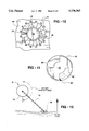
FIG. 1 is a side view of a rotary encoder according to the invention;
FIG. 2 is a front view of the circuit board of the encoder of FIG. 1;
FIG. 3 is a rear view of the encoder disk of the encoder of FIG. 1;
FIG. 4 is a schematic diagram of an electronic circuit for the encoder of FIG. 1;
FIGS. 5A and 5B are clocking and driving waveforms used in the circuit of FIG. 4;
FIG. 6 is a set of current waveforms developed by the circuit of FIG. 4;
FIG. 7 is a set of current waveforms for the several phases developed by the circuit of FIG. 4;
FIGS. 8A-8D are summed current waveforms for certain phases;
FIG. 9 is a graph of a phase signal developed by the circuit of FIG. 4;
FIG. 10 is a front view of the circuit board of a second embodiment of the encoder of FIG. 1, according to the invention;
FIG. 11 is a rear view of the encoder disk of the second embodiment of the encoder of FIG. 1; and
FIG. 12 is a front view of a rotary encoder in a liquid level sensor, according to the invention.
DESCRIPTION OF THE INVENTION
Referring to FIG. 1, a rotary encoder 8 comprises a stationary circuit board 10, a rotary disk 12 which is also a circuit board, a shaft 14 for holding the disk, and a bearing 16 on the circuit board 10 for rotatably mounting the shaft 14 which extends through a hole 18 in the circuit board 10. To produce signals representing the position of the shaft or an input device driving the shaft, conductive patterns on the board 10 and disk 12 are capacitively coupled according to disk angular position, and excitation signals are applied to the conductive patterns. The resultant signals are analyzed to determine the angular position. An integrated circuit 19 containing the electronic circuits discussed below is mounted on the circuit board 10.
FIG. 2 shows the conductive pattern applied to the circuit board 10. It includes a central pickup pad 20 surrounding the hole 18, an annular shield 22 around the pickup pad, and a circular array at least three conductive of segments 24 surrounding the shield. The shield 22 prevents capacitive coupling between the edges of the pickup pad 20 and the edges of the segments 24. Each of the segments 24 is designated as .O slashed.A-.O slashed.E according to the phase of its respective excitation signal. In this example eight segments are used.
The conductive pattern 26 on the disk 12 is an encoder pattern as shown in FIG. 3. It has a center circular portion 28 surrounding the shaft 14 and directly opposed to the pickup pad 20, and an outer portion 30 extending around half the disk and overlying half the segment array. In one position of the disk the outer portion will align with the segments .O slashed.A-.O slashed.D, and if rotated slightly, it will align with .O slashed.B-.O slashed.D and only portions of segments .O slashed.A and .O slashed.E, and so forth. The disk 12 is mounted sufficiently close to the circuit board 10 to capacitively couple the encoder pattern to the pickup pad and the segment array. Excitation signals imposed on the segments are coupled to the encoder pattern in proportion to the extent that any segment is aligned with or overlaps the encoder pattern. These coupled signal are summed on the encoder and coupled to the pickup pad 20. By selecting suitable excitation signals, the summed signal on the pickup pad will reflect the position of the rotor as a phase angle. This arrangement of capacitively coupled conductors 20-26 on the disk and on the circuit board comprises a rotary sensor 32.
The circuit which drives and detects this sensor 32 is shown in FIG. 4. A counter 34 comprising a prescaler 36 and a main counter 38 is clocked by a clock signal which causes the prescaler to count every clock pulse and issue a carry signal which is coupled to a clock enable pin of the main counter 38. Thus the main counter is clocked once for each complete cycle of the prescaler. The main counter is preferably a 9 bit counter and its outputs are coupled to pins IN0 to IN8 of a logic circuit 40. The outputs .O slashed.A-.O slashed.H of the output logic are digital waveforms which are identical but differing in phase; each signal is delayed by 64 counts of the main counter from an adjacent signal. For example, .O slashed.B begins its sequence 64 counts after .O slashed.A begins its sequence. The entire sequence repeats for each waveform every 512 counts of the main counter. These outputs along with the inputs IN0-IN8 are shown in FIGS. 5A and 5B which cover one half of a complete cycle. Thus IN8 remains low until the end of FIG. 5B and then remains high for the other half of the main counter cycle, not shown. The signal IN0 is the base count of the main counter 38 and comprises a continuous stream of high frequency digital pulses.
Each of the output signals .O slashed.A-.O slashed.H comprises streams of high frequency pulses interrupted by a group of four pulses at half the main counter frequency, a break lasting for eight main counter pulses, and resuming with another four lower frequency pulses. The phase of the pulses changes after each break. For example, in FIG. 5A .O slashed.B is initially in phase with the main counter signal IN0 and after the break it is in inverse phase with IN0. The signals .O slashed.E-.O slashed.H are the logical inverses of .O slashed.A-.O slashed.D, respectively. The waveform sequences appear to be very complex but they are easily derived from the main counter outputs with a small number of gates.
Referring again to FIG. 4, the waveforms .O slashed.A-.O slashed.H output from the logic circuit are each coupled to one of the segments 24 which, along with the encoder pattern, comprises one of the capacitors CA-CH. The pickup pad 20 and the encoder pattern 26 comprise another capacitor CP which couples the summed signals out of the sensor 32. That output is coupled to V/2 via a resistor 42 and to a synchronous detector 44. The detector 44 includes an analog switch 48 operated by the main counter signal IN0 which is fed through a delay circuit 50. One switch 48 output is connected to a capacitor 52 and a second output is connected to capacitor 54 to develop a differential phase signal. A differential amplifier 56 is coupled to the two capacitors and the amplified phase output is connected through a switched capacitor low pass filter 58 to a comparator 60 referenced to V/2 to determine the zero crossing point of the phase signal. A latch 62 has a first section 62A having inputs coupled to the main counter outputs and a second section 62B having inputs coupled to the prescaler outputs. Both latch sections are clocked by the zero crossing signal from the comparator 60 so that the latched output will be a precise measure of the phase angle which is the measure of the encoder angular position.
The analog switch control input is derived from IN0 and is delayed to guarantee that the analog switch state is held stable when signals .O slashed.A-.O slashed.H switch. With this arrangement, charge is pumped by the transitions present on the signals .O slashed.A-.O slashed.H through the sensor capacitors, CA-CH and through the pickup capacitor, CP, to the capacitors 52 and 54. The capacitors 52 and 54 are alternately connected to the pickup capacitor CP by the analog switch 48. It can be seen that 1) rising edges increase the voltage and falling edges decrease the voltage; and 2) similarly, rising and falling edges present on signals .O slashed.A-.O slashed.H that are inverted in phase with respect to IN0 cause charge to be pumped to and from capacitor 54. This is illustrated for .O slashed.A in FIG. 6. The bottom two traces show the current pulses into capacitors 52 and 54 as a result of the transitions on .O slashed.A as a function of main counter counts. The top two traces show the number and polarity of current pulses occurring in each eight count interval, an average current. One waveform is the exact negative of the other; the differential nature of these two signals is important for noise rejection. The other seven drive signals generate similar waveforms but with different phase relationships. FIG. 6 does not reflect the reduction of amplitudes occurring when a capacitance CA-CH is less than the maximum value due to partial coupling of a segment with the encoder pattern.
The currents contributed by each of the eight drive signals are summed by the sensor in proportion to their respective capacitors CA--CH. FIG. 7 shows maximum average current for each of the eight drive waveforms for capacitor 52. FIGS. 8A-8D respectively show the summed currents for .O slashed.A through .O slashed.D (0°), .O slashed.B through .O slashed.E (45°), .O slashed.C through .O slashed.F (90°), and .O slashed.D through .O slashed.G (135°). Intermediate positions are not shown. For each increment of encoder rotation the summed current waveform (and the resulting voltage waveform) is correspondingly shifted linearly. Thus by measuring the phase angle the encoder position is also measured. The capacitor voltage waveform is the integrated capacitor current waveform and is shown in FIG. 9. This is the voltage waveform for the sum of .O slashed.A through .O slashed.D or 0°. The zero crossing point is measured at the crossing of the decreasing voltage. A phase shift due to the low pass filter causes a small offset of 0 count from 0°. The switched capacitor filter 58 causes the offset to be constant with temperature. Also a switched capacitor filter can be implemented totally in silicon without external components to thereby minimize its cost.
To develop the phase signal, the differential amplifier 56 differentially amplifies the voltage on capacitors 52 and 54. The filter 58 is a second order low pass filter inserted after the amplifier 56 to remove some distortion which is possible due to the encoder crossing between the various drive signal phases. The phase signal is biased to swing about V/2 and is compared to V/2 with the analog comparator 60 to determine the zero crossing point. The output of the comparator 60 is synchronized to the system clock and the main counter is then latched.
Latching the main counter value gives nine bit resolution. Each count of the main counter latch corresponds to 360/512 degrees of rotation. The prescaler counter 36 allows the position of the zero crossing of the phase signal to be discriminated with additional accuracy. Adding prescaler bits increases resolution, but increases the required clock frequency. A binary prescaler with P bits resolves each count of the main counter into 2P prescaler counts. Each count of the prescaler latch then corresponds to 360/(512* 2P) degrees of rotation.
Additional resolution can be obtained by adding multiple cycles of the drive waveforms to the circuit board and encoder disk patterns. The same sequence of drive waveforms .O slashed.A-.O slashed.H is repeated more than once around the periphery of the encoder, and the encoder disk pattern is modified to couple to the multiple cycles of the drive signals. A two cycle pattern is shown in FIGS. 10 and 11. The segment array includes 16 segments 24' so that each drive signal is applied to two different segments. The encoder disk pattern 26' is shaped as a center circular portion 28' with two outer lobes 30' to simultaneously couple to corresponding segments in each cycle. The behavior of a multiple cycle encoder is similar to a single cycle encoder with the exception that the measurement is performed over a decreased angular span (360/N) where N is the number of cycles. The position measurement is no longer absolute, the measurement repeats N times over 360 degrees. An up/down counter can be incorporated to keep track of which cycle the measurement is on with simple logic. Some means must be included to initialize this counter to correspond to the desired cycle on power-up to get an accurate reading. An eight cycle encoder has been successfully operated.
In the examples illustrated herein eight segments per cycle and corresponding eight driving waveforms are employed. Other numbers may be used however. It is expected that as few as three segments and driving signals could be used, although with lower resolution.
FIG. 12 illustrates an application of the rotary encoder as a fluid level sensor of the type used in vehicles to measure the level of fuel in a tank. A float 70 on an arm 72 drives the encoder disk 74 of a rotary encoder 76 as a function of the fluid level. The encoder 76 is like the encoder 8 discussed above. As fluid level changes, the encoder disk is rotated as fluid level varies. The fluid level does not have any minimum or maximum limits, and the encoder will travel up to 180°.
Some advantages of the capacitive rotary fuel level sensor are:
1) The sensor provides a digital output which is a function of fluid level. This digital information can be directly transmitted from a remote location by integrating a serial transmitter into the electronics. The digital format leads to greater accuracy since the variable resistance of the vehicle harness is not a factor.
2) External noise is eliminated. Typical analog sensors on the other hand are extremely sensitive to power supply noise and line noise.
3) Microprocessor interface to this sensor is inexpensive via serial interface, whereas typical analog sensors require expensive analog to digital converters.
4) There is no requirement for the electrical parts to make moving contact as in a resistive potentiometer or to be otherwise exposed. Where the sensor is exposed to corrosive elements, the metal portions are readily encapsulated in plastic or other protective coating and can be safely used in fuel containing corrosive liquids such as alcohol. In contrast, analog sensors require expensive protection to avoid corrosion including special low current circuits to reduce the effects of electrolytic destruction.
5) A loading impedance required for analog sensors is not required.
It will thus be seen that the rotary capacitive encoder can be used in many applications and is especially desirable where low cost, high accuracy, extremely high resolution, robustness and reliability are desired. In addition to the fuel level sensor described above, some of those applications in a vehicle are feedback of a gauge pointer position, a throttle position sensor, a suspension system sensor, air controls air door position sensor, a rotary switch or knob position sensor, and an attitude sensor.

Claims (7)

We claim:
1. A rotary position encoder comprising:
a circuit board having at least three conductive segments in a circular array and a pickup conductor concentric with the array;
an encoder disk mounted adjacent the circuit board for rotation about an axis concentric with the array;
means for supplying a pattern of digital signals to the conductive segments, the signal patterns differing in phase for each segment;
means for selectively summing the signals as a function of rotary position of the encoder disk comprising an encoder conductor on the disk capacitively coupled with some of the segments according to the rotational position;
the encoder conductor including a region capacitively coupled with the pickup conductor so that for segments coupled to the encoder conductor the respective signals will be summed and coupled to the pickup conductor;
a detector circuit connected to the pickup conductor for producing a phase signal; and
means for determining the phase of the phase signal wherein the phase is a measure of the rotational position of the encoder disk.
2. The invention as defined in claim 1 wherein:
the detector circuit comprises a synchronous detector connected to the pickup conductor for receiving the summed signals and producing a differential phase signal; and
a differential amplifier is coupled to the detector circuit for amplifying the differential phase signal.
3. The invention as defined in claim 1 wherein the means for determining the phase of the phase signal includes a zero crossing detector.
4. The invention as defined in claim 1 wherein the means for supplying a pattern of digital signals comprises:
a counter for generating a plurality of count outputs; and
a logic circuit coupled to the count outputs for generating the pattern of digital signals.
5. The invention as defined in claim 4 wherein the circuit for determining the phase of the phase signal includes:
a zero crossing detector coupled to the phase signal for producing a zero crossing signal; and
a latch clocked by the zero crossing signal and having data inputs comprising the count outputs, whereby the count latched by the zero crossing signal is a measure of the phase.
6. The invention as defined in claim 5 wherein the counter comprises:
a main counter providing count outputs to the logic circuit and to the latch; and
a prescaler providing count outputs to the latch, whereby the count latched by the zero crossing signal is expanded to increase the resolution of the phase measurement.
7. The invention as defined in claim 1 wherein the conductive segments in an array which are supplied by the pattern of signals comprise one of a plurality of groups of corresponding segments which are replicated in other parts of the array and supplied by the same pattern of signals, and the encoder conductor is formed to selectively sum the signals from corresponding segments of all the groups.
US08/714,740 1996-09-16 1996-09-16 Capacitive rotary position encoder Expired - Lifetime US5736865A (en)

Priority Applications (2)

Application Number Priority Date Filing Date Title
US08/714,740 US5736865A (en) 1996-09-16 1996-09-16 Capacitive rotary position encoder
US08/984,923 US5941122A (en) 1996-09-16 1997-12-04 Liquid level sensor incorporating a capacitive rotary position encoder

Applications Claiming Priority (1)

Application Number Priority Date Filing Date Title
US08/714,740 US5736865A (en) 1996-09-16 1996-09-16 Capacitive rotary position encoder

Related Child Applications (1)

Application Number Title Priority Date Filing Date
US08/984,923 Division US5941122A (en) 1996-09-16 1997-12-04 Liquid level sensor incorporating a capacitive rotary position encoder

Publications (1)

Publication Number Publication Date
US5736865A true US5736865A (en) 1998-04-07

Family

ID=24871272

Family Applications (2)

Application Number Title Priority Date Filing Date
US08/714,740 Expired - Lifetime US5736865A (en) 1996-09-16 1996-09-16 Capacitive rotary position encoder
US08/984,923 Expired - Fee Related US5941122A (en) 1996-09-16 1997-12-04 Liquid level sensor incorporating a capacitive rotary position encoder

Family Applications After (1)

Application Number Title Priority Date Filing Date
US08/984,923 Expired - Fee Related US5941122A (en) 1996-09-16 1997-12-04 Liquid level sensor incorporating a capacitive rotary position encoder

Country Status (1)

Country Link
US (2) US5736865A (en)

Cited By (29)

* Cited by examiner, † Cited by third party
Publication number Priority date Publication date Assignee Title
US5961574A (en) * 1997-01-08 1999-10-05 Woodfield; David Alan Device for obtaining positional information
EP1026478A1 (en) * 1999-02-02 2000-08-09 C.R.F. Società Consortile per Azioni Driving and position detecting unit for a rotatable member
US6118283A (en) * 1997-10-20 2000-09-12 Methode Electronics, Inc. Capacitive rotary position sensor
US6157280A (en) * 1998-11-09 2000-12-05 Siemens Aktiengesellschaft Switchable gradient coil arrangement
US6587093B1 (en) 1999-11-04 2003-07-01 Synaptics Incorporated Capacitive mouse
US6603319B1 (en) * 1998-06-16 2003-08-05 Oki Electric Industries Co., Ltd. Water immersion detecting circuit
US20030214938A1 (en) * 2002-03-21 2003-11-20 Jindal Deepak Kumar Method for routing of label switched paths (LSPS) through an internet supporting multi-protocol label switching (MPLS) technology
US20040189327A1 (en) * 2003-03-31 2004-09-30 Mr. Steven Al-Rawi Capacitive sensor
US20050156881A1 (en) * 2002-04-11 2005-07-21 Synaptics, Inc. Closed-loop sensor on a solid-state object position detector
US20060032587A1 (en) * 2000-09-29 2006-02-16 Infineon Technolgies Ag Device for connecting two wafers in a planar manner for grinding down and cutting up a product wafer
US20060143981A1 (en) * 2005-01-04 2006-07-06 Toseland Bernard A Dehydrogenation of liquid fuel in microchannel catalytic reactor
US20080047765A1 (en) * 2005-04-07 2008-02-28 Microsoft Corporation Circular Touch Sensor
US20090091336A1 (en) * 2007-10-04 2009-04-09 Steven Basil Al-Rawi Capacitive Position Sensor
US20090134886A1 (en) * 2007-11-26 2009-05-28 Guangjin Li Angle-measuring device with an absolute-type disk capacitive sensor
US7825797B2 (en) 2006-06-02 2010-11-02 Synaptics Incorporated Proximity sensor device and method with adjustment selection tabs
US20110175629A1 (en) * 2008-08-04 2011-07-21 The Regents Of The University Of California Capacitance displacement and rotation sensor
US20110174972A1 (en) * 2009-12-15 2011-07-21 The Regents Of The University Of California Apparatus and methods for controlling electron microscope stages
DE102010046778A1 (en) 2010-09-28 2012-03-29 Trw Automotive Electronics & Components Gmbh Capacitive encoder
US8779783B1 (en) * 2013-03-12 2014-07-15 Cypress Semiconductor Corporation Mutual capacitance sensing using a self-capacitance sensing device
US8847611B2 (en) 2011-10-18 2014-09-30 The Board Of Trustees Of The Leland Stanford Junior University Capacitive differential quadrature rotary position sensor
EP2824426A1 (en) 2013-07-09 2015-01-14 Leica Geosystems AG Capacitative rotation angle sensor
US9092082B2 (en) 2010-12-22 2015-07-28 Synaptics Incorporated Methods and apparatus for mounting a touch sensor device
RU2581078C2 (en) * 2011-03-30 2016-04-10 Текем Энерджи Сервисиз Гмбх Device and method for capacitance reading of rotary motion of rotary element
US9513152B1 (en) 2011-12-20 2016-12-06 Varec, Inc. Liquid level transmitter utilizing low cost, capacitive, absolute encoders
US20170115136A1 (en) * 2015-10-23 2017-04-27 Miele & Cie. Kg Method and rotational angle sensor for measuring an angular position of a rotatable signal-inducing unit
US9910531B2 (en) 2015-01-12 2018-03-06 Synaptics Incorporated Circular outline single layer pattern
US10209117B1 (en) 2008-09-17 2019-02-19 Varec, Inc. Method and system for measuring and managing inventory of product in a collapsible tank
CN109540178A (en) * 2018-12-20 2019-03-29 金卡智能集团股份有限公司 A kind of counting structure judging character wheel position based on capacitance
US20220244078A1 (en) * 2021-02-02 2022-08-04 Cypress Semiconductor Corporation Capacitive differential rotary encoder

Families Citing this family (5)

* Cited by examiner, † Cited by third party
Publication number Priority date Publication date Assignee Title
US6367325B1 (en) 2000-01-13 2002-04-09 Visteon Global Technologies, Inc. Motor vehicle fuel level sensor
US6591483B1 (en) 2000-04-04 2003-07-15 The Cherry Corporation Method of forming a spatially fine magnetic structure
CN102519554A (en) * 2011-11-21 2012-06-27 程有信 Capacitor type differential operation floater liquid level sensor
WO2016029204A1 (en) * 2014-08-22 2016-02-25 Ksr Ip Holdings Llc. Inductive sensor
DE102016222849B4 (en) * 2016-11-21 2024-03-14 Audi Ag Method for calibrating a level display

Citations (3)

* Cited by examiner, † Cited by third party
Publication number Priority date Publication date Assignee Title
US4788546A (en) * 1984-10-29 1988-11-29 Mitutoyo Mfg. Co., Ltd. Electrostatic capacity type encoder
US4842387A (en) * 1987-02-06 1989-06-27 Hitachi, Ltd. Automatic focusing apparatus for use in video camera and the like
US4879552A (en) * 1985-05-23 1989-11-07 Mitutoyo Mfg. Co., Ltd. Variable capacitance type encoder

Family Cites Families (3)

* Cited by examiner, † Cited by third party
Publication number Priority date Publication date Assignee Title
US4160239A (en) * 1977-11-25 1979-07-03 Chevron Research Company Transponder system including an oscillator/ripple counter controlling a fixed Gray code logic network in circuit with a decoder/driver network for generating "red alert" end condition digital signals in a storage tank gauging system
US4313114A (en) * 1980-05-30 1982-01-26 Leupold & Stevens, Inc. Liquid level recorder apparatus and method for storing level differences in memory
US5596188A (en) * 1992-07-01 1997-01-21 Whessoe Varec, Inc. Clock recovery system and rotational detection circuit

Patent Citations (3)

* Cited by examiner, † Cited by third party
Publication number Priority date Publication date Assignee Title
US4788546A (en) * 1984-10-29 1988-11-29 Mitutoyo Mfg. Co., Ltd. Electrostatic capacity type encoder
US4879552A (en) * 1985-05-23 1989-11-07 Mitutoyo Mfg. Co., Ltd. Variable capacitance type encoder
US4842387A (en) * 1987-02-06 1989-06-27 Hitachi, Ltd. Automatic focusing apparatus for use in video camera and the like

Cited By (50)

* Cited by examiner, † Cited by third party
Publication number Priority date Publication date Assignee Title
US5961574A (en) * 1997-01-08 1999-10-05 Woodfield; David Alan Device for obtaining positional information
US6118283A (en) * 1997-10-20 2000-09-12 Methode Electronics, Inc. Capacitive rotary position sensor
US6603319B1 (en) * 1998-06-16 2003-08-05 Oki Electric Industries Co., Ltd. Water immersion detecting circuit
US6157280A (en) * 1998-11-09 2000-12-05 Siemens Aktiengesellschaft Switchable gradient coil arrangement
EP1026478A1 (en) * 1999-02-02 2000-08-09 C.R.F. Società Consortile per Azioni Driving and position detecting unit for a rotatable member
US20060038783A1 (en) * 1999-11-04 2006-02-23 Shaw Scott J Capacitive mouse
US20110001703A1 (en) * 1999-11-04 2011-01-06 Synaptics Incorporated Capacitive mouse
US7817135B2 (en) 1999-11-04 2010-10-19 Synaptics Incorporated Capacitive mouse
US20110001704A1 (en) * 1999-11-04 2011-01-06 Synaptics Incorporated Capacitive mouse
US6587093B1 (en) 1999-11-04 2003-07-01 Synaptics Incorporated Capacitive mouse
US8035616B2 (en) 1999-11-04 2011-10-11 Synaptics Incorporated Capacitive mouse
US20060032587A1 (en) * 2000-09-29 2006-02-16 Infineon Technolgies Ag Device for connecting two wafers in a planar manner for grinding down and cutting up a product wafer
US20030214938A1 (en) * 2002-03-21 2003-11-20 Jindal Deepak Kumar Method for routing of label switched paths (LSPS) through an internet supporting multi-protocol label switching (MPLS) technology
US8259076B2 (en) 2002-04-11 2012-09-04 Synaptics Incorporated Closed-loop sensor on a solid-state object position detector
US20080042976A1 (en) * 2002-04-11 2008-02-21 Synaptics Incorporated Closed-loop sensor on a solid-state object position detector
US7466307B2 (en) 2002-04-11 2008-12-16 Synaptics Incorporated Closed-loop sensor on a solid-state object position detector
US20060187216A1 (en) * 2002-04-11 2006-08-24 Synaptics, Inc. Closed-loop sensor on a solid-state object position detector
US8669943B2 (en) 2002-04-11 2014-03-11 Synaptics Incoporated Closed-loop sensor on a solid-state object position detector
US7710407B2 (en) 2002-04-11 2010-05-04 Synaptics Incorporated Closed-loop sensor on a solid-state object position detector
US20050156881A1 (en) * 2002-04-11 2005-07-21 Synaptics, Inc. Closed-loop sensor on a solid-state object position detector
US20040189327A1 (en) * 2003-03-31 2004-09-30 Mr. Steven Al-Rawi Capacitive sensor
US20060143981A1 (en) * 2005-01-04 2006-07-06 Toseland Bernard A Dehydrogenation of liquid fuel in microchannel catalytic reactor
US20080047765A1 (en) * 2005-04-07 2008-02-28 Microsoft Corporation Circular Touch Sensor
US7786981B2 (en) * 2005-04-07 2010-08-31 Microsoft Corporation Circular touch sensor
US7825797B2 (en) 2006-06-02 2010-11-02 Synaptics Incorporated Proximity sensor device and method with adjustment selection tabs
US20090091336A1 (en) * 2007-10-04 2009-04-09 Steven Basil Al-Rawi Capacitive Position Sensor
US20090134886A1 (en) * 2007-11-26 2009-05-28 Guangjin Li Angle-measuring device with an absolute-type disk capacitive sensor
US8093915B2 (en) * 2007-11-26 2012-01-10 Guilin Gemred Sensor Technology Ltd. Angle-measuring device with an absolute-type disk capacitive sensor
US20110175629A1 (en) * 2008-08-04 2011-07-21 The Regents Of The University Of California Capacitance displacement and rotation sensor
US8704536B2 (en) 2008-08-04 2014-04-22 The Regents Of The University Of California Lateral displacement and rotational displacement sensor
US10209117B1 (en) 2008-09-17 2019-02-19 Varec, Inc. Method and system for measuring and managing inventory of product in a collapsible tank
US9103769B2 (en) 2009-12-15 2015-08-11 The Regents Of The University Of California Apparatus and methods for controlling electron microscope stages
US20110174972A1 (en) * 2009-12-15 2011-07-21 The Regents Of The University Of California Apparatus and methods for controlling electron microscope stages
DE102010046778A1 (en) 2010-09-28 2012-03-29 Trw Automotive Electronics & Components Gmbh Capacitive encoder
WO2012041498A1 (en) 2010-09-28 2012-04-05 Trw Automotive Electronics & Components Gmbh Capacitive rotary transducer
US9250058B2 (en) 2010-09-28 2016-02-02 Trw Automotive Electronics & Components Gmbh Capacitive rotary encoder
US9092082B2 (en) 2010-12-22 2015-07-28 Synaptics Incorporated Methods and apparatus for mounting a touch sensor device
RU2581078C2 (en) * 2011-03-30 2016-04-10 Текем Энерджи Сервисиз Гмбх Device and method for capacitance reading of rotary motion of rotary element
US8847611B2 (en) 2011-10-18 2014-09-30 The Board Of Trustees Of The Leland Stanford Junior University Capacitive differential quadrature rotary position sensor
US9513152B1 (en) 2011-12-20 2016-12-06 Varec, Inc. Liquid level transmitter utilizing low cost, capacitive, absolute encoders
US8779783B1 (en) * 2013-03-12 2014-07-15 Cypress Semiconductor Corporation Mutual capacitance sensing using a self-capacitance sensing device
CN104280053A (en) * 2013-07-09 2015-01-14 莱卡地球系统公开股份有限公司 Capacitive rotary position encoder and capacitive rotary position detection method
EP2824426A1 (en) 2013-07-09 2015-01-14 Leica Geosystems AG Capacitative rotation angle sensor
US9441990B2 (en) 2013-07-09 2016-09-13 Leica Geosystems Ag Capacitive rotary position encoder
US9910531B2 (en) 2015-01-12 2018-03-06 Synaptics Incorporated Circular outline single layer pattern
US20170115136A1 (en) * 2015-10-23 2017-04-27 Miele & Cie. Kg Method and rotational angle sensor for measuring an angular position of a rotatable signal-inducing unit
US10113885B2 (en) * 2015-10-23 2018-10-30 Miele & Cie. Kg Method and rotational angle sensor for measuring an angular position of a rotatable signal-inducing unit
CN109540178A (en) * 2018-12-20 2019-03-29 金卡智能集团股份有限公司 A kind of counting structure judging character wheel position based on capacitance
CN109540178B (en) * 2018-12-20 2024-03-19 金卡智能集团股份有限公司 Counting structure for judging position of character wheel based on capacitance
US20220244078A1 (en) * 2021-02-02 2022-08-04 Cypress Semiconductor Corporation Capacitive differential rotary encoder

Also Published As

Publication number Publication date
US5941122A (en) 1999-08-24

Similar Documents

Publication Publication Date Title
US5736865A (en) Capacitive rotary position encoder
US4490674A (en) Rotational angle detection device having two magnetoresistive sensing elements
US5880586A (en) Apparatus for determining rotational position of a rotatable element without contacting it
US6304079B1 (en) Incremental rotary encoder for measuring horizontal or vertical angles
US5311666A (en) Rotary displacement measuring apparatus
US5929631A (en) Method of position sensing utilizing giant magneto resistance elements and solid state switch array
US6914543B2 (en) Method for initializing position with an encoder
US4866382A (en) Magnetic rotary encoder system having a multi-element magnetoresistive sensor
Brasseur A robust capacitive angular position sensor
US7406883B2 (en) Compact device for measuring the speed and the direction of rotation of an object
US20030218840A1 (en) Device for generating output voltages
GB2163852A (en) Measuring apparatus using magnetoresistance elements
US20020171417A1 (en) Angle detector with magnetoresistive sensor elements
WO2003021207A1 (en) Liquid level sensor device
US7323864B2 (en) Absolute angular position sensor on 360 of a rotating element
US5252824A (en) Analog transmitter of position and direction of rotation having a signal amplitude varies on each change of state of sensors
CN114459511B (en) Magnetic encoder and working method thereof
Bhaskarrao et al. A simple signal conditioner for tunneling magneto-resistance based angle sensor
CN116067404A (en) High-precision absolute value magnetic encoder and signal processing method thereof
EP0372136B1 (en) Magnetic rotary encoder system
JP2001091298A (en) Noncontact magnetic type measuring device
Li et al. A novel low-cost noncontact resistive potentiometric sensor for the measurement of low speeds
US4532600A (en) Electronic integrating meter
JPH0571985A (en) Data output encoder
Li et al. A new method for the measurement of low speed using a multiple-electrode capacitive sensor

Legal Events

Date Code Title Description
AS Assignment

Owner name: DELCO ELECTRONICS CORPORATION, INDIANA

Free format text: ASSIGNMENT OF ASSIGNORS INTEREST;ASSIGNORS:NELSON, JAMES EDWARD;SELBY, RONALD KENNETH;LIPPMANN, RAYMOND;AND OTHERS;REEL/FRAME:008177/0904

Effective date: 19960829

STCF Information on status: patent grant

Free format text: PATENTED CASE

FPAY Fee payment

Year of fee payment: 4

FPAY Fee payment

Year of fee payment: 8

AS Assignment

Owner name: DELPHI TECHNOLOGIES INC., MICHIGAN

Free format text: ASSIGNMENT OF ASSIGNORS INTEREST;ASSIGNOR:DELCO ELECTRONICS CORPORATION;REEL/FRAME:017115/0208

Effective date: 20050930

FPAY Fee payment

Year of fee payment: 12