US5740357A - Generic fault management of a computer system - Google Patents
Generic fault management of a computer system Download PDFInfo
- Publication number
- US5740357A US5740357A US08/329,800 US32980094A US5740357A US 5740357 A US5740357 A US 5740357A US 32980094 A US32980094 A US 32980094A US 5740357 A US5740357 A US 5740357A
- Authority
- US
- United States
- Prior art keywords
- error
- fault
- handler
- hierarchy
- level
- Prior art date
- Legal status (The legal status is an assumption and is not a legal conclusion. Google has not performed a legal analysis and makes no representation as to the accuracy of the status listed.)
- Expired - Lifetime
Links
Images


Classifications
-
- G—PHYSICS
- G06—COMPUTING; CALCULATING OR COUNTING
- G06F—ELECTRIC DIGITAL DATA PROCESSING
- G06F11/00—Error detection; Error correction; Monitoring
- G06F11/07—Responding to the occurrence of a fault, e.g. fault tolerance
- G06F11/0703—Error or fault processing not based on redundancy, i.e. by taking additional measures to deal with the error or fault not making use of redundancy in operation, in hardware, or in data representation
- G06F11/0706—Error or fault processing not based on redundancy, i.e. by taking additional measures to deal with the error or fault not making use of redundancy in operation, in hardware, or in data representation the processing taking place on a specific hardware platform or in a specific software environment
- G06F11/0709—Error or fault processing not based on redundancy, i.e. by taking additional measures to deal with the error or fault not making use of redundancy in operation, in hardware, or in data representation the processing taking place on a specific hardware platform or in a specific software environment in a distributed system consisting of a plurality of standalone computer nodes, e.g. clusters, client-server systems
-
- G—PHYSICS
- G06—COMPUTING; CALCULATING OR COUNTING
- G06F—ELECTRIC DIGITAL DATA PROCESSING
- G06F11/00—Error detection; Error correction; Monitoring
- G06F11/07—Responding to the occurrence of a fault, e.g. fault tolerance
- G06F11/0703—Error or fault processing not based on redundancy, i.e. by taking additional measures to deal with the error or fault not making use of redundancy in operation, in hardware, or in data representation
- G06F11/0793—Remedial or corrective actions
Definitions
- the present invention relates to computer systems, and more specifically, to the managing of faults in a computer system.
- Fault management is the management of the abnormal operation of a computer system.
- a computer system may comprise many individual components coupled together. Since faults may be thought of as, the underlying cause of abnormal system operation, the purpose of fault management is to return a computer system to normal operation. Therefore, fault management encompasses the entire process of managing faults from their detection to their logical and/or physical removal from the system. Fault management encompasses the handling of faults after they occur, and does not encompass the avoidance of faults.
- a system is defined as an interacting set of subsystems that provide a service to a user (or client).
- the service delivered by the system is the behavior of the system as specified by the user.
- the subsystems within the system can be further subdivided into additional subsystems, to a desired level of detail.
- a system failure occurs when the delivered service (as observed by the user) deviates from the specified service.
- An error occurs when a portion of the system assumes an undesirable condition.
- An error observed at the output of the system by the user is considered a failure.
- a fault is considered to be the underlying cause of an error, although it may or may not be physically identified. Faults may originate from hardware, software, human, or environmental sources. In summary, a fault is the root cause which in turn may result in an error. If the effects of the error are observed by the user of a service, a failure results.
- a fault In order for a fault to cause an error, a fault must be both active and stimulated (affecting the service provided by the system). An error must be detected in order to control the results of the service. Undetected errors are not manageable and the integrity of the system may be compromised. Error detection is a necessary prerequisite for error recovery. Error recovery (fault tolerance) ultimately dictates the user response: success if the service was recovered, or failure if the service could not be recovered.
- Error detection is the act of recognizing a difference between the current, actual behavior of an entity and the expected behavior.
- the ability to detect errors is a prerequisite to fault management. After detection, the error condition must be communicated to a function that can deal appropriately with (i.e. handle) the error condition. This function is called error handling and is performed by the error handler.
- error recovery When an error condition is detected, it is most desirable to remove the effect of the error to complete the specified service request. This is the responsibility of the error handler, referred to as error recovery. If error recovery is successful, a success response is returned to the user. Because it determines what service response (success if recovered, or failure if not recovered) must be returned to the user, error handling must be performed synchronously with the respective service.
- error handling is ultimately responsible for processing an error event within the context of a single service request/response.
- error handling may remove the effect of an error, it has no bearing whatsoever on the originating fault, since the fault will remain in the system.
- fault repair Aside from removing the effects of errors from the system, it is also important to remove the source of these errors: the faults.
- the process of removing faults from a system (which is called fault repair) is the responsibility of the fault handler. Fault handling may be performed asynchronously to the corresponding error handling as it has no impact on the outcome of the error recovery.
- the error handler delivers an error information report to the fault handler.
- the error handler will learn of the error before the fault handler will learn of the underlying fault, since errors are the detectable results of faults. Before the repair can take place, it is imperative that information about the fault is available.
- the fault handler uses the error information report (possibly along with previous reports) to determine the location of the fault and to initiate repair activity.
- the repair or removal of a fault may be physical (such as the replacement of a part, or the installation of a software patch), or logical (such as bad page mapping).
- the repair can be either temporary or permanent.
- the present invention separates error recovery techniques and fault repair techniques into error handling and fault handling components.
- the method of managing faults in a computer system according to the present invention includes the steps of detecting an error, handling the error along a functional hierarchy, and handling the fault that caused the error, this fault handling being performed in a management hierarchy that is separate from the functional hierarchy.
- error handling and fault handling components allows effective management of faults within the computer system while minimizing the impact of faults within the components of the computer system.
- error handling and fault handling into different hierarchies allows error handling to be performed synchronously with the functional operation of the system, and the fault handling to be performed asynchronously.
- a management element is attached to each component in the computer system that provides a service (a service element).
- the management element includes an error detector that compares the expected behavior of the service element with its actual behavior. If the error detector detects a difference between the expected and the actual behaviors, an error report is sent to an error handler.
- the error handler attempts error recovery with the service element. Regardless of the success of this error recovery, the error information is passed to a fault handler in the management element.
- the fault handler will attempt to repair the fault in the service element so that the error will not recur.
- the error handler and the fault handler in the fault management element can use a tester that will test the service element to gather further information or verify recovery and repair actions executed by the error handler and/or fault handler.
- FIG. 1 shows an embodiment of a computer system having a functional hierarchy and a management hierarchy.
- FIG. 2 shows an embodiment of a fault management element.
- FIG. 3 illustrates in greater detail the error detector used in the embodiment of the management agent of FIG. 2 constructed in accordance with an embodiment of the present invention.
- FIG. 4 illustrates in more detail an error handler used in the management agent of FIG. 2 constructed in accordance with an embodiment of the present invention.
- FIG. 5 illustrates a fault handler used in the management agent of FIG. 2 constructed in accordance with an embodiment of the present invention.
- FIG. 6 shows in more detail a tester used in the management agent of FIG. 2 constructed in accordance with an embodiment of the present invention.
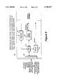
- FIG. 1 illustrates an example of a computer system 10.
- the system comprises a number of individual manageable system components, hereinafter referred to as entities 12a-12f.
- the entities 12f, e, c form a functional hierarchy for a particular service in which higher level entities are considered to be the clients for the services provided by the lower level entities.
- Each entity 12a-12f comprises a service element 14, e.g. a disk drive, a CPU, etc. which performs a primary function of the entity, and a management agent 17 that represents the management functionality and the management interface for the entity 12.
- Each management agent 17 includes a fault management element 16, which will be described in more detail later.
- the first hierarchy the functional hierarchy
- This functional hierarchy is represented by the solid lines between the entities 12c, 12e and 12f.
- entity 12c is the client of the services provided by entity 12e, which is the client of the services provided by entity 12f.
- the second type of hierarchy is a management hierarchy that is independent of the functional hierarchy.
- the management hierarchy exists to allow the management of the individual entities 12a-12f.
- the dashed lines in FIG. 1 represent the couplings of the management agents 17 of the individual service elements 12a-12f.
- higher level entities manage lower level entities by sending management requests and receiving corresponding responses.
- the functional hierarchy can be different than the management hierarchy. This allows the error detection and handling to follow a different path than the fault handling and repair.
- the error handling hierarchy must follow the functional hierarchy (i.e. be synchronous with the service operation) whereas the fault handling hierarchy does not need to follow the functional hierarchy (i.e. is asynchronous with it).
- FIG. 2 An example of a fault management element 16 is illustrated in FIG. 2.
- the fault management element 16 comprises five components--error detector 30, error handler 40, fault handler 50, tester 60, and control 70.
- the individual components of the fault management element 16 will be described in more detail later with reference to FIGS. 3-6. The functional operation of these components will be described below.
- the error detector 30 monitors the behavior of the service element 14 by comparing expected behavior with actual, observed behavior. When a difference (error) is detected, the return of a service response to the client (i.e. the next higher level entity in the functional hierarchy) is delayed until the result of error handling becomes available. Upon the detection of a difference, the error detector 30 notifies and provides corresponding error information to the error handler 40.
- error detector 30 can be changed by the tester 60 in order to test, enable, disable or change error detection algorithms.
- error detectors include parity detectors and cyclic redundancy check (CRC checks) in hardware.
- CRC checks cyclic redundancy check
- error detectors include boundary pages, data structure consistency checks, and time-outs. Syntax checking is done to detect administration errors. Furthermore, temperature or voltage detection checks are performed to detect environmental errors.
- the error handler 40 evaluates each error that is passed from the error detector 30 to determine if the error is recoverable. The error handler 40 drives the attempted recovery until it is successful or exhausted. Error information is always provided from the error handler 40 to the fault handler 50, regardless of the success of the attempted recovery.
- Error recovery is achieved by either retrying the failed function (in which case the error handler 40 may simply reissue the original client request), or via correction of the error within the error handler 40.
- the error handler 40 can also use the tester 60 in order to refine the information that is required for successful error recovery. For example, the error handler 40 could cause testing of which bit of a double bit error is solid in order to correct the error.
- the error handler 40 returns and responds to the error detector 30 to indicate the success or failure of the recovery attempt (the recovery status).
- the attempted recovery must be finished before a final response is returned to the user.
- error handling is performed synchronously with the service requested by the client.
- error handling examples include: correction of a single bit in hardware; collection of missing input parameters for a software routine; correction of a syntax error and retry of an operation after a power failure. These are merely examples, and other types of errors can be handled.
- the fault handler 50 acts upon error information received from the error handler 40. Fault handler 50 analyzes the error information and attempts to determine the location of the fault, and then initiates the appropriate repair action. In doing so, the fault handler 50 can employ the services of the tester 60 to refine the error information in its attempt to isolate the fault. The repair activities initiated by the fault handler 50 use services available to it for the particular fault under investigation.
- Verification of the repair action is also controlled by the fault handler 50. This may be done by using the tester 60 to apply stimuli (excite) and observe the behavior. Another verification method is performed by waiting for a designated period of time in which the same error does not recur. The repair status feedback is required in order to complete the repair activity.
- the reversal of previous repair activity may be initiated if it is determined later that the repair was incorrect or incomplete.
- a temporary repair may also be reversed once a permanent repair plan has been initiated.
- fault handling examples include bypassing of failed services; fail-over to redundant services; fault diagnosis algorithms to determine failing replaceable services; requesting the physical exchange of a part or upgrading to a new revision/path level etc. by a repair agent.
- the tester 60 corresponds to the test capabilities available to the fault management element 16. It can be used by either the error handler 40 or the fault handler 50. It can also be used by higher level entities via the control function. Accordingly, requests are sent by either the error handler 40 or the fault handler 50 and the tester 60 returns corresponding responses.
- the tester 60 provides various stimuli to the service element 14 for different functions. One stimulus enables/disables or changes the detection algorithms of the error detector 30 as directed by the error handler 40. The result of this action is observed by the error handler 40 through the signals Error Flag and Info sent by the error detector 30, or by the absence of such notification.
- Another stimulus checks the error detector by inserting a fault, modifies the detection algorithms, applies stimuli and receives the result directly from the error detector 30.
- the signal Error Flag and Info to the error handler 40 can be disabled in this situation.
- Another stimulus from the tester 60 excites less frequently-used functions by applying the stimuli and embodving the result directly at the tester 60.
- the status is returned to the initiator of the test, either the error handler 40 or the fault handler 50.
- Another stimulus applies stress and observes the result directly at the tester 60. Again, the status is returned to the initiator of the test, either the fault handler 50 or the error handler 40.
- the control 70 is the part of the management agent 16 which allows higher level fault management elements 16 to control specific, predetermined attributes of the components 30, 40, 50 and 60 in the local level management agent 12. Therefore, the control 70 interprets management requests, performs the requested function if correctly validated, and provides a corresponding management response. In an embodiment of the present invention, the control 70 also forwards higher level management requests to lower levels. In this embodiment, control 70 also forwards management responses from the lower level to the requesting higher level.
- the control 70 allows the error handler 40, the fault handler 50 and the tester 60 at a local level to have access to lower level counterparts. In other words, the control 70 allows communication between fault handlers 50 and error handlers 40 within a management agent 16, or between separate management agents 16 on different levels.
- error handling entails removing the effects of errors in order to provide correct service
- error handling must co-exist within the functional hierarchy, indicated by the solid lines in FIG. 1. Therefore, the error handling hierarchy is the same as the functional hierarchy.
- a success/fail response is used to synchronize error detection and error handling within the functional hierarchy.
- the error report interface is used to provide information necessary for error handling from one level to another level. If an error is not detected at a particular level, the error detector 30 passes the success response on to the next level. If a fail response is received from a lower level, or if an error is detected at the local level, the response to the next higher level is delayed until error handling is complete.
- the error can be detected at the local level, in which case the error handler 40 will attempt recovery as described above.
- the third possibility is for a fail response without an associated error report being received from the lower level. In this case, the error handler 40 may use a management request/response exchange via the control 70 to gather more information from a lower level error handler 40. If the recovery is successful, a success response is sent to the next higher level. If the recovery is not successful, a fail response and error report (if applicable) is sent to the next higher level.
- Error information will be sent to the local level fault handler 50 to allow repair activity to be evaluated within the fault handling hierarchy.
- a fault handler 50 may send a fault report to higher level fault handlers 50.
- Fault handling at a particular level begins when the fault handler 50 receives an error information report from the error handler 40 at the local level, or when the fault handler 50 receives a fault report from a lower level fault handler 50.
- the fault handler 50 attempts to determine the required repair activity as described earlier.
- the control 70 can be used by a local level fault handler 50 and the resulting management request/response to request further information from a lower level fault handler 50.
- the local level fault handler 50 may use the tester 60 of lower levels to refine the fault information. Further, the fault handler 50 may attempt or request repair by sending a fault report to the next higher level. Fault handler 50 can verify a repair, by using tester 60 at the local or lower levels.
- the fault reports are sent up the management hierarchy.
- Thresholds (not shown) can be used to prevent each report from being passed up, and cause a fault report to be passed further up the management hierarchy only when the same fault has been reported a predetermined number of times.
- the error detector 30, the error handler 40, the fault handler 50, and the tester 60 have all been described generally with reference with FIG. 2. A more detailed description of each of these components is provided below with reference to FIGS. 3-6.
- the error detector 30 is shown in more detail in FIG. 3. As stated earlier, the error detector 30 monitors the behavior of the service element 14 by comparing its expected behavior to its actual behavior. The error detector 30 notifies and provides corresponding error information to the error handler 40 upon detection of a difference.
- the error detector 30 is the conceptual location of one or more detection points of a given entity 12. Each entity 12 defines the relationship between detection points and components of the error detector 30. For example, an entity can have many detection points and as many error detectors 30.
- the error detector 30 Upon receiving a success response from a lower level entity, the error detector 30 merely passes the success response to a synchronizer 36. After the synchronizer receives the success response and if an error is not detected at the local level, the success response is provided from the synchronizer 36 to the next higher level entity in the functional hierarchy.
- the detection points 32 inhibit the return of a service response until activity at this local level is complete. A failed service response received from the lower level entity in the functional hierarchy will result in the same inhibition.
- Error information (the error report) is collected by the collector 31 in conjunction with the detection of unexpected behavior or a fail response. This error report may originate locally, or may be contained within an error report received synchronously with the fail response from the lower level entity.
- the collector 31 provides an error flag and error information (Error Fag and Info) to the error handler 40. If recovery is successful, the error handler 40 unstalls the stalled service response, and returns a success response to the next higher level entity by providing the recovery status to the synchronizer 36. If recovery was not possible, the recovery status provided to the synchronizer 36 causes a failed response to be sent to the next higher level entity. Synchronously with this fail response, the error handler 40 may send an error report containing additional error information to the next higher level entity.
- the tester 60 can modify the detection points 32 or observe behavior to verify that the detection points 32 are functioning properly.
- the tester 60 can also request that the Error Flag and Info from the collector 31 be sent to the tester 60.
- the control 70 can also read or modify the detection points 32 via the access function 33.
- the error handler 40 is shown in greater detail in FIG. 4. As stated earlier, the error handler 40 attempts recovery from an error. The error handler 40 evaluates every error detected by the error detector 30 for recoverability. The error handler 40 drives the attempted error recovery until it is either successful or exhausted. The error handler 40 returns status information to the error detector 30 and passes information to the fault handler 50 and to the higher level error detector 30, if appropriate.
- an analyze function 41 controls the error handler 40.
- the analyze function 41 executes a plan of action for a specific error that is reported by the error detector 30. Depending upon the error, the error handler 40 performs certain steps. Activity starts in the error handler 40 when an Error Flag and Info is received from the error detector 30. The plan of action is selected based upon the error symptom indicated by the Error Flag and Info. More information can be collected from the local level entity 12 or from a lower level entity 12 via an access function 43.
- the access function 43 provides a request/response access to and from the control 70 and the tester 60.
- the tester 60 may be used by the error handler 40 to refine the information available for error recovery. Using a recover function 45, a specific recovery operation may be requested to the local level service element 14. The corresponding response will indicate success or failure of the recovery operation. If the error was detected at the local level, the analyze function 41 generates the required error information and incorporates it into any corresponding error report. If the error was detected by a lower level entity and reported to this local level by an error report, the local level error handler 40 adds an entity identification (i.d.) plus any additional information to a corresponding error report that it generates.
- entity identification i.d.
- Success or failure of a recovery attempt by the recover function 45 is reported back to the error detector 30. Unsuccessful recovery will cause the analyze function 41 to pass error information on to the next higher level entity in an error report through a reporting function 44. The error report is synchronized with the corresponding fail response which travels up the functional path to the next higher level entity. The error information at the local level will be passed to the fault handler 50 regardless of recovery success or failure.
- the recover function 45 performs and controls specific recovery operations. One method of recovery retries the failed operation. In this case, the recover function 45 becomes the client of the corresponding functional path. It is therefore the service client and receives a service response.
- the recover function 45 returns the success indicator to the analyze function 41 as a response to the recovery operation request.
- the analyze function 41 in return returns a success recovery status to the error detector 30, which enables unstalling of the service response to the higher level entity.
- an unsuccessful service response is returned to the recover function 45.
- This unsuccessful service response is passed along to the analyzer function 41.
- the analyzer function 41 can attempt more retrys or other types of recovery operations. If the error cannot be recovered, the analyzer function 41 returns a failed recovery status to the error detector 30 which will then send a failed response to the higher level entity.
- the error handler 50 can also send an error report to the client.
- the access function 43 allows management of the local level error handler 40 by a higher level entity 12.
- Some of this management of the local level error handler 40 includes reading and writing of a scratch pad function 42 that serves as temporary storage of error, state, and status information; access to and control of analyzer function 41 attributes, such as counters and error handling thresholds; switching the reporting function 44 to report to the tester 60 instead of to the fault handler 50, or to the next higher level entity; and for diagnostic purposes, the higher level entity 12 may change the reporting function 44 to report only to the tester 60 via the access function 43.
- the reporting function 44 is controlled by the analyzer function 41, which provides the error information and directs the sending of this information.
- the reporting function 44 sends error information to the local level fault handler 50, and if recovery was unsuccessful, it may send an error report to the next higher level entity.
- fault handling is the process that attempts to temporarily or permanently remove a fault from the system. Fault handling proceeds even if the error is recovered by error handling, because even a fully-tolerated fault should be removed for performance reasons to prevent repetition of error recovery, and to maintain a high level of fault tolerance.
- An embodiment of the fault handler 50 is shown in FIG. 5.
- a fault analysis function 51 controls the fault handler 50. It receives the fault reports from lower level fault handlers 50, and Error Info from the error handler 40 at this level.
- the fault handler 50 Depending upon the specific fault, certain steps are performed by the fault handler 50. Activity starts when error information is received from the error handler 40 or a fault report from a lower level fault handler 50. A plan of action for fault handling is then selected based upon the specific error that has been reported. The plan of action controls analysis of the information received, with the goal of the plan being to isolate the fault and select and initiate a repair action. More information can be collected from the error handlers 40 at the local level or from a lower level via an access function 53. The tester 60 can be used to refine the information available for repair by running diagnostics. The access function 53 is again used to accomplish this task.
- a specific repair action may be requested from a repair function 55.
- the corresponding response from the repair function 55 indicates the success or failure of the repair action.
- a Service Already Initiated Flag is set in the fault report if the request for the service agent has already been made. If a higher level fault handler 50 is required to request the involvement of a service agent, the Initiate Service Required Flag is set in the fault report. Verification of the repair action is also controlled by the fault analysis function 51. This could be done by using the tester 60 to apply stimuli and observe the behavior, or by waiting for a designated time in which the same error does not recur. The reversal of previous repair activity may be initiated if it is determined later that the repair is based on a premature or incomplete diagnosis or to implement a permanent repair after a temporary repair had been instituted.
- the repair function 55 controls repair action by using services made available for the particular fault under investigation.
- the services include, among others, configuration management to bypass failed parts, failover to redundant parts, and fault recovery mechanisms such as mapping bad disk blocks or memory pages.
- the repair function may also request the physical exchange of a part or an upgrade to a new revision by a service agent.
- the required repair action as determined by the fault analysis 51 function can differ for every individual product and every individual error. Therefore, individual algorithms must be defined for each product and error. Repair analysis is well-known to those of ordinary skill in the art. Specific fault analysis algorithms are well-known to those of ordinary skill in the art of product repair.
- Classification of repair actions can be simplified by the accurate definition of repair levels, which in turn facilitates the corresponding analysis by higher level fault handler 50.
- One definition of a repair action is no repair in which the fault cannot be isolated and removed or that a repair is not needed.
- a second definition of a repair action is temporary repair, where the fault may have been removed and service upgraded, so that further repair action is required.
- a third definition of a repair action is permanent repair, in which the fault has been removed logically or physically and no further repair action is required.
- the fault handler 50 may abandon attempts to repair the fault. In this case, the fault handler 50 reports any repair actions to the next highest level fault handler 50 along with the results of those actions. This procedure allows the higher level fault handler 50 to continue the attempted repair.
- the repair process involves several functions of the fault handler 50.
- the report function 54 sends fault reports to higher level fault handlers 50, as directed by them.
- the access function 53 permits the local level fault handler 50 to obtain access to report filters of lower level fault handler 50 and their record functions 52.
- the access function 53 also allows a higher level fault handler 50 to control the setting of the local level's report filters and access to its record function 52.
- the record function 52 serves as the memory for the fault analysis and the repair functions.
- the record function 52 contains all the available information for any repair activity in progress at this local level. Once a fault is repaired, the repair actions are made available for storage by the analyze function 51.
- test directed diagnosis 63 (TDD).
- TDD test directed diagnosis 63
- the TDD 63 accomplishes its task by one of a number of different methods. One method uses the normal functions of the service element by using available on-line diagnostics. Another method uses the TDD function 63 of the local level entity 12; another uses the TDD functions of lower level entities; and another uses fault insertion.
- test strategies may be provided by the tester 60.
- One strategy is the test directed diagnosis in which less frequently used functions, and diagnostic functions of the entity, are excited via an excite function 65. The results are observed directly by an observe function 61.
- An access function 64 is used to return the corresponding status to the initiator of the test.
- test strategy is stress testing.
- normal functions are excited at maximum rate and/or over extended periods of time to stress-test the entity 12.
- the results are observed by the observe function 61.
- the access function 64 returns the status to the initiator of the test.
- a third test strategy is the fault insertion strategy, which is performed by modifying the detection points 32 of the error detector 30. This is done by using the fault insert function 62 of the tester 60. In an operation, the service element is excited and will cause the error detector 30 to detect an error. Error flag and error data are reported directly to the observe function 61 of the tester 60 by the collect function 31 in the error detector 30. This allows verification of the error detecting signaling mechanism and the detected symptom information. The error flag and error data are reported to the error handler 40. This can be the result of a test initiated by the error handler 50 (for example, which bit of a double bit error is the solid bad bit).
- the corresponding test would be complete in this case, as the initiator of the corresponding TDD function 63 had received the corresponding response.
- the test can also be controlled by the TDD function 63, which would have changed the report function in the error handler 40 to send the error report to the observe function 61 in the tester 60. This allows testing of the error detector 30 and the error handler 40.
- Error flag and error data are reported to the fault handler 50. This can be the result of the test initiated by the fault handler 50, for example, to verify a repair action. The corresponding test would be complete in this case, as the initiator of the corresponding TDD function 63 had received the corresponding response. The test could also be controlled by the TDD function 63, which would have changed the report function in the fault handler 50 to report the fault report to the observe function 61 in the tester component. This allows testing of the error detector 30, error handler 40 and fault handler 50.
- error handling is attempted over multiple levels up to the highest level entity in the functional hierarchy. Error handling takes place until recovery is successful or recovery possibilities are exhausted. If the error was recovered, a success response is reported to the client. The error report stops at the level where the error is recovered. If the error could not be recovered, the corresponding fail response, plus possibly an error report, reaches the client.
- an error handler 40 at the local level has no knowledge whether the error handler 40 in the next higher level will be able to recover from an error. Therefore, the error handler 40 cannot determine whether the error will be recovered by the higher level.
- the error reporting rule is that an error handler which detects an error places all error information which may be required for error recovery at a higher level into the error report, or stores it at the local level. The error handler must report every error, whether recovered or unrecovered, to the fault handler at the local level. This report should contain all the information which may be required for fault isolation and repair in order to make fault handling possible.
- fault reports are not normally generated to travel along the fault handling hierarchy for such errors. If such an error is reported to a fault handler 50, the complete information required for fault handling is made available.
- Higher level management relies on management information from all lower levels for which it has been assigned the manager. For example, the highest level management, the network manager, must know about all of the entities coupled to the network to properly manage the network.
- the management hierarchy is set up by the network manager and it remains in effect until changed by management request.
- the fault reporting path which follows the management hierarchy, is static and may be different from the path used for error reports.
- the fault reporting path is always the same for a given entity until it is changed by management.
- fault handling does not occur synchronously with a client service request, but may be performed later (i.e. asynchronously).
- fault reports are delivered in their sequence of occurrence. Since fault reporting may be restricted by the setting of the fault handler report filters, there is no guarantee that all fault reports generated due to a single error are reported. Therefore, one fault information rule is that the fault handler 50 can be capable of preserving all error information received from the error handler 40 that may be required for fault repair.
- fault reports from lower level fault handlers 50 may not carry the complete information relating to the fault. Therefore, another rule is that the fault handler 50 generates fault reports for all errors which are unrecoverable at the corresponding level.
- Management domains may be crossed by a single client service request or response. If an error occurs on such a request, the corresponding error report will also cross those domains. However, fault reports will follow the fault handling hierarchy within the respective domains only and the corresponding service response, which may be an error report. Fault reports are restricted to a domain while error reports are not. Accordingly, fault reports from a low level entity may travel up a different management path than successive fault reports from higher level entities involved in the specific client service request. This leads to the rule that fault handling across management domains requires fault handlers which are visible across the corresponding domains.
- the fault handling typically involves multiple fault handling levels.
- an error considered fatal to one level may not be of interest to a higher level.
- a fatal disk problem may cause activity in the fault handler responsible for disk errors, yet may not be of concern to the fault handler at the next highest level.
- a lower level fault handler that determines that higher level repair involvement is required may need to report this via the normal fault reporting path, yet the higher level fault handler may not recognize the receipt of the fault report nor act upon it.
- Another problem is that the lower level fault handler that determines that repair action is required may need to report this via the normal fault report path, yet the higher level fault handler 50 may not recognize the received fault report nor act upon it.
- Another potential problem is that the lower level fault handler 50 that determines that repair action is required may want to allow a higher level fault handler 50 to add value. However, there is no simple way for the lower level fault handler 50 to assure that the higher level fault handler 50 does not perform the value-adding service.
- a third potential problem is that the lower level fault handler 50 may have access to a path to initiate repair. The corresponding fault report that flows up to higher levels of fault management could trigger another request for repair from those higher level, which would be redundant.
- fault reports can include a field that carries an Initiate Repair Flag and one that carries a Repair Already Initiated Flag.
Abstract
Description
Claims (8)
Priority Applications (1)
| Application Number | Priority Date | Filing Date | Title |
|---|---|---|---|
| US08/329,800 US5740357A (en) | 1990-04-26 | 1994-10-26 | Generic fault management of a computer system |
Applications Claiming Priority (3)
| Application Number | Priority Date | Filing Date | Title |
|---|---|---|---|
| US51518090A | 1990-04-26 | 1990-04-26 | |
| US6088493A | 1993-05-12 | 1993-05-12 | |
| US08/329,800 US5740357A (en) | 1990-04-26 | 1994-10-26 | Generic fault management of a computer system |
Related Parent Applications (1)
| Application Number | Title | Priority Date | Filing Date |
|---|---|---|---|
| US6088493A Continuation | 1990-04-26 | 1993-05-12 |
Publications (1)
| Publication Number | Publication Date |
|---|---|
| US5740357A true US5740357A (en) | 1998-04-14 |
Family
ID=26740461
Family Applications (1)
| Application Number | Title | Priority Date | Filing Date |
|---|---|---|---|
| US08/329,800 Expired - Lifetime US5740357A (en) | 1990-04-26 | 1994-10-26 | Generic fault management of a computer system |
Country Status (1)
| Country | Link |
|---|---|
| US (1) | US5740357A (en) |
Cited By (78)
| Publication number | Priority date | Publication date | Assignee | Title |
|---|---|---|---|---|
| WO1998039870A2 (en) * | 1997-03-07 | 1998-09-11 | Mci Worldcom, Inc. | System and method for managing network resources using distributed intelligence and state management |
| US6115643A (en) * | 1998-02-03 | 2000-09-05 | Mcms | Real-time manufacturing process control monitoring method |
| WO2001050262A1 (en) * | 1999-12-30 | 2001-07-12 | Intel Corporation | Cooperative error handling system |
| US20010042227A1 (en) * | 2000-05-11 | 2001-11-15 | Patrick Stephenson | Graceful degradation system |
| US6334193B1 (en) * | 1997-05-29 | 2001-12-25 | Oracle Corporation | Method and apparatus for implementing user-definable error handling processes |
| WO2002023338A2 (en) * | 2000-09-18 | 2002-03-21 | Tenor Networks, Inc. | System resource availability manager |
| US6363494B1 (en) * | 1998-06-19 | 2002-03-26 | At&T Corp | System and method for characterizing and repairing intelligent systems |
| US6385665B1 (en) * | 1998-12-18 | 2002-05-07 | Alcatel Usa Sourcing, L.P. | System and method for managing faults in a data transmission system |
| US6401119B1 (en) * | 1998-09-18 | 2002-06-04 | Ics Intellegent Communication Software Gmbh | Method and system for monitoring and managing network condition |
| US20020087687A1 (en) * | 2000-09-18 | 2002-07-04 | Tenor Networks,Inc. | System resource availability manager |
| US20020162045A1 (en) * | 2001-04-27 | 2002-10-31 | Nec Corporation | Communication device that performs automatic failure recovery and automatic failure recovery method |
| US6477667B1 (en) * | 1999-10-07 | 2002-11-05 | Critical Devices, Inc. | Method and system for remote device monitoring |
| US20020176577A1 (en) * | 2001-05-25 | 2002-11-28 | Intel Corporation | Digital signature collection and authentication |
| US20030093516A1 (en) * | 2001-10-31 | 2003-05-15 | Parsons Anthony G.J. | Enterprise management event message format |
| US20030126516A1 (en) * | 2001-12-28 | 2003-07-03 | Komarla Eshwari P. | Scalable CPU error recorder |
| US6636991B1 (en) * | 1999-12-23 | 2003-10-21 | Intel Corporation | Flexible method for satisfying complex system error handling requirements via error promotion/demotion |
| US6654903B1 (en) * | 2000-05-20 | 2003-11-25 | Equipe Communications Corporation | Vertical fault isolation in a computer system |
| US6665262B1 (en) | 1999-02-16 | 2003-12-16 | Telefonaktiebolaget Lm Ericsson (Publ) | Distributed fault management architecture |
| US6691250B1 (en) | 2000-06-29 | 2004-02-10 | Cisco Technology, Inc. | Fault handling process for enabling recovery, diagnosis, and self-testing of computer systems |
| US6708291B1 (en) * | 2000-05-20 | 2004-03-16 | Equipe Communications Corporation | Hierarchical fault descriptors in computer systems |
| US6715097B1 (en) * | 2000-05-20 | 2004-03-30 | Equipe Communications Corporation | Hierarchical fault management in computer systems |
| US6718486B1 (en) * | 2000-01-26 | 2004-04-06 | David E. Lovejoy | Fault monitor for restarting failed instances of the fault monitor |
| US20040073829A1 (en) * | 1998-07-16 | 2004-04-15 | Olarig Sompong P. | Fail-over of multiple memory blocks in multiple memory modules in computer system |
| US6754855B1 (en) * | 1999-12-01 | 2004-06-22 | Microsoft Corporation | Automated recovery of computer appliances |
| US6760722B1 (en) * | 2000-05-16 | 2004-07-06 | International Business Machines Corporation | Computer implemented automated remote support |
| US20040169644A1 (en) * | 2000-12-29 | 2004-09-02 | Intel Corporation | Wireless display systems and stylii |
| US6789114B1 (en) * | 1998-08-05 | 2004-09-07 | Lucent Technologies Inc. | Methods and apparatus for managing middleware service in a distributed system |
| US20040177340A1 (en) * | 2003-03-07 | 2004-09-09 | Han-Wen Hsu | Firmware structuring method and related apparatus for unifying handling of execution responses of subroutines |
| EP1460541A2 (en) * | 2003-01-16 | 2004-09-22 | Siemens Aktiengesellschaft | Method for monitoring functional components in tree structures |
| US20050089153A1 (en) * | 2003-06-17 | 2005-04-28 | Qubica S.P.A. | Method and a system for managing at least one event in a bowling establishment |
| US6901582B1 (en) | 1999-11-24 | 2005-05-31 | Quest Software, Inc. | Monitoring system for monitoring the performance of an application |
| US6983362B1 (en) | 2000-05-20 | 2006-01-03 | Ciena Corporation | Configurable fault recovery policy for a computer system |
| US7047523B1 (en) * | 1999-06-02 | 2006-05-16 | Siemens Aktiengesellschaft | System for determining a total error description of at least one part of a computer program |
| US20060184823A1 (en) * | 2005-02-17 | 2006-08-17 | Kunihito Matsuki | Access control device and interface installed in same |
| US7117397B1 (en) * | 1999-12-15 | 2006-10-03 | Fujitsu Limited | Apparatus and method for preventing an erroneous operation at the time of detection of a system failure |
| US20060268725A1 (en) * | 2005-05-25 | 2006-11-30 | International Business Machines Corporation | Operating network managers in verification mode to facilitate error handling of communications networks |
| US20070050671A1 (en) * | 2005-08-30 | 2007-03-01 | Markevitch James A | Selective error recovery of processing complex using privilege-level error discrimination |
| US20070067673A1 (en) * | 2005-08-19 | 2007-03-22 | Algirdas Avizienis | Hierarchical configurations in error-correcting computer systems |
| US20070118560A1 (en) * | 2005-11-21 | 2007-05-24 | Christof Bornhoevd | Service-to-device re-mapping for smart items |
| US20070118496A1 (en) * | 2005-11-21 | 2007-05-24 | Christof Bornhoevd | Service-to-device mapping for smart items |
| US20070130208A1 (en) * | 2005-11-21 | 2007-06-07 | Christof Bornhoevd | Hierarchical, multi-tiered mapping and monitoring architecture for service-to-device re-mapping for smart items |
| US20070168201A1 (en) * | 2006-01-06 | 2007-07-19 | Chellam Sudhakar V | Formula for automatic prioritization of the business impact based on a failure on a service in a loosely coupled application |
| US20070233881A1 (en) * | 2006-03-31 | 2007-10-04 | Zoltan Nochta | Active intervention in service-to-device mapping for smart items |
| US20070283002A1 (en) * | 2006-05-31 | 2007-12-06 | Christof Bornhoevd | Modular monitor service for smart item monitoring |
| US20070282988A1 (en) * | 2006-05-31 | 2007-12-06 | Christof Bornhoevd | Device registration in a hierarchical monitor service |
| US20080126857A1 (en) * | 2006-08-14 | 2008-05-29 | Robert Beverley Basham | Preemptive Data Protection for Copy Services in Storage Systems and Applications |
| US20080244331A1 (en) * | 2007-03-28 | 2008-10-02 | Grimes Andrew W | System and Method for In-Band Problem Log Data Collection Between a Host System and a Storage System |
| US20080320332A1 (en) * | 2007-06-21 | 2008-12-25 | Joanna Katharine Brown | Error Processing Across Multiple Initiator Network |
| US7519701B1 (en) | 2008-02-15 | 2009-04-14 | International Business Machines Corporation | System and method of propagating status among related entities |
| US7580994B1 (en) * | 2004-01-21 | 2009-08-25 | Nortel Networks Limited | Method and apparatus for enabling dynamic self-healing of multi-media services |
| EP2101264A2 (en) * | 2008-03-06 | 2009-09-16 | Continental Automotive GmbH | Method for error treatment and tachography system |
| EP1410205B1 (en) | 1999-09-06 | 2010-03-31 | Sperling, Axel | Method and device for monitoring and controlling the operational performance of a computer system or processor system |
| US20100115348A1 (en) * | 2008-07-29 | 2010-05-06 | Frank Van Gilluwe | Alternate procedures assisting computer users in solving problems related to error and informational messages |
| WO2010112974A2 (en) * | 2009-03-31 | 2010-10-07 | Freescale Semiconductor, Inc. | System for tree sequence testing of a device and method for tree sequence testing of a device in a test framework architecture |
| US7979245B1 (en) | 2006-05-17 | 2011-07-12 | Quest Software, Inc. | Model-based systems and methods for monitoring computing resource performance |
| US8065411B2 (en) | 2006-05-31 | 2011-11-22 | Sap Ag | System monitor for networks of nodes |
| US8175863B1 (en) | 2008-02-13 | 2012-05-08 | Quest Software, Inc. | Systems and methods for analyzing performance of virtual environments |
| US8185598B1 (en) | 2006-11-03 | 2012-05-22 | Quest Software, Inc. | Systems and methods for monitoring messaging systems |
| US8327189B1 (en) | 2009-12-22 | 2012-12-04 | Emc Corporation | Diagnosing an incident on a computer system using a diagnostics analyzer database |
| US20130081027A1 (en) * | 2011-09-23 | 2013-03-28 | Elwha LLC, a limited liability company of the State of Delaware | Acquiring, presenting and transmitting tasks and subtasks to interface devices |
| US20130086589A1 (en) * | 2011-09-30 | 2013-04-04 | Elwha Llc | Acquiring and transmitting tasks and subtasks to interface |
| US8862570B1 (en) | 2004-03-02 | 2014-10-14 | Rockstar Consortium Us Lp | Method and apparatus for open management of multi-media services |
| US9098444B2 (en) * | 2013-03-12 | 2015-08-04 | Dell Products, Lp | Cooperative data recovery in a storage stack |
| US9141495B2 (en) | 2013-03-12 | 2015-09-22 | Dell Products, Lp | Automatic failure recovery using snapshots and replicas |
| US9215142B1 (en) | 2011-04-20 | 2015-12-15 | Dell Software Inc. | Community analysis of computing performance |
| US9269063B2 (en) | 2011-09-23 | 2016-02-23 | Elwha Llc | Acquiring and transmitting event related tasks and subtasks to interface devices |
| US9274758B1 (en) | 2015-01-28 | 2016-03-01 | Dell Software Inc. | System and method for creating customized performance-monitoring applications |
| US9479414B1 (en) | 2014-05-30 | 2016-10-25 | Dell Software Inc. | System and method for analyzing computing performance |
| US9557879B1 (en) | 2012-10-23 | 2017-01-31 | Dell Software Inc. | System for inferring dependencies among computing systems |
| US9996577B1 (en) | 2015-02-11 | 2018-06-12 | Quest Software Inc. | Systems and methods for graphically filtering code call trees |
| US10187260B1 (en) | 2015-05-29 | 2019-01-22 | Quest Software Inc. | Systems and methods for multilayer monitoring of network function virtualization architectures |
| US10200252B1 (en) | 2015-09-18 | 2019-02-05 | Quest Software Inc. | Systems and methods for integrated modeling of monitored virtual desktop infrastructure systems |
| US10223188B2 (en) * | 2012-05-09 | 2019-03-05 | Infosys Limited | Method and system for detecting symptoms and determining an optimal remedy pattern for a faulty device |
| US10230601B1 (en) | 2016-07-05 | 2019-03-12 | Quest Software Inc. | Systems and methods for integrated modeling and performance measurements of monitored virtual desktop infrastructure systems |
| US10291493B1 (en) | 2014-12-05 | 2019-05-14 | Quest Software Inc. | System and method for determining relevant computer performance events |
| US10333820B1 (en) | 2012-10-23 | 2019-06-25 | Quest Software Inc. | System for inferring dependencies among computing systems |
| US11005738B1 (en) | 2014-04-09 | 2021-05-11 | Quest Software Inc. | System and method for end-to-end response-time analysis |
| US11249883B2 (en) | 2020-01-02 | 2022-02-15 | Bank Of America Corporation | Error repair tool using sentiment analysis |
Citations (6)
| Publication number | Priority date | Publication date | Assignee | Title |
|---|---|---|---|---|
| US4085448A (en) * | 1976-10-04 | 1978-04-18 | International Business Machines Corporation | Data communication bus structure |
| US4342084A (en) * | 1980-08-11 | 1982-07-27 | International Business Machines Corporation | Main storage validation means |
| US4438494A (en) * | 1981-08-25 | 1984-03-20 | Intel Corporation | Apparatus of fault-handling in a multiprocessing system |
| US4453213A (en) * | 1981-07-30 | 1984-06-05 | Harris Corporation | Error reporting scheme |
| US4468731A (en) * | 1981-12-15 | 1984-08-28 | Honeywell Information Systems Inc. | Identification apparatus for use in a controller to facilitate the diagnosis of faults |
| US4570261A (en) * | 1983-12-09 | 1986-02-11 | Motorola, Inc. | Distributed fault isolation and recovery system and method |
-
1994
- 1994-10-26 US US08/329,800 patent/US5740357A/en not_active Expired - Lifetime
Patent Citations (6)
| Publication number | Priority date | Publication date | Assignee | Title |
|---|---|---|---|---|
| US4085448A (en) * | 1976-10-04 | 1978-04-18 | International Business Machines Corporation | Data communication bus structure |
| US4342084A (en) * | 1980-08-11 | 1982-07-27 | International Business Machines Corporation | Main storage validation means |
| US4453213A (en) * | 1981-07-30 | 1984-06-05 | Harris Corporation | Error reporting scheme |
| US4438494A (en) * | 1981-08-25 | 1984-03-20 | Intel Corporation | Apparatus of fault-handling in a multiprocessing system |
| US4468731A (en) * | 1981-12-15 | 1984-08-28 | Honeywell Information Systems Inc. | Identification apparatus for use in a controller to facilitate the diagnosis of faults |
| US4570261A (en) * | 1983-12-09 | 1986-02-11 | Motorola, Inc. | Distributed fault isolation and recovery system and method |
Non-Patent Citations (10)
| Title |
|---|
| Fernandez, J., "SNA and OSI: Which Manages Multivendor Networks Best?", Data Communications, Apr. 1989. |
| Fernandez, J., SNA and OSI: Which Manages Multivendor Networks Best , Data Communications , Apr. 1989. * |
| Huntington, J., "OSI-Based Net Management: Is it Too Early or Too Late?", Data Communications, Mar. 1989. |
| Huntington, J., OSI Based Net Management: Is it Too Early or Too Late , Data Communications , Mar. 1989. * |
| Lew, H., et al., "TCP/IP network management with an eye toward OSI", Data Communications, Aug. 1989, pp. 123-130. |
| Lew, H., et al., TCP/IP network management with an eye toward OSI , Data Communications , Aug. 1989, pp. 123 130. * |
| Retz, D., "TCP/IP:DOD suite marches into the business world", Data Communications, Nov. 1987, pp. 209-225. |
| Retz, D., TCP/IP:DOD suite marches into the business world , Data Communications , Nov. 1987, pp. 209 225. * |
| Wakid, S. et al., "Coming to OSI: Network Resource Management and Global Reachability", Data Communications, Dec. 1987. |
| Wakid, S. et al., Coming to OSI: Network Resource Management and Global Reachability , Data Communications , Dec. 1987. * |
Cited By (136)
| Publication number | Priority date | Publication date | Assignee | Title |
|---|---|---|---|---|
| WO1998039870A2 (en) * | 1997-03-07 | 1998-09-11 | Mci Worldcom, Inc. | System and method for managing network resources using distributed intelligence and state management |
| WO1998039870A3 (en) * | 1997-03-07 | 1998-10-29 | Mci Communications Corp | System and method for managing network resources using distributed intelligence and state management |
| US6052722A (en) * | 1997-03-07 | 2000-04-18 | Mci Communications Corporation | System and method for managing network resources using distributed intelligence and state management |
| US6334193B1 (en) * | 1997-05-29 | 2001-12-25 | Oracle Corporation | Method and apparatus for implementing user-definable error handling processes |
| US6115643A (en) * | 1998-02-03 | 2000-09-05 | Mcms | Real-time manufacturing process control monitoring method |
| US6363494B1 (en) * | 1998-06-19 | 2002-03-26 | At&T Corp | System and method for characterizing and repairing intelligent systems |
| US20040073829A1 (en) * | 1998-07-16 | 2004-04-15 | Olarig Sompong P. | Fail-over of multiple memory blocks in multiple memory modules in computer system |
| US7055054B2 (en) * | 1998-07-16 | 2006-05-30 | Hewlett-Packard Development Company, L.P. | Fail-over of multiple memory blocks in multiple memory modules in computer system |
| US6789114B1 (en) * | 1998-08-05 | 2004-09-07 | Lucent Technologies Inc. | Methods and apparatus for managing middleware service in a distributed system |
| US6401119B1 (en) * | 1998-09-18 | 2002-06-04 | Ics Intellegent Communication Software Gmbh | Method and system for monitoring and managing network condition |
| US6385665B1 (en) * | 1998-12-18 | 2002-05-07 | Alcatel Usa Sourcing, L.P. | System and method for managing faults in a data transmission system |
| US6665262B1 (en) | 1999-02-16 | 2003-12-16 | Telefonaktiebolaget Lm Ericsson (Publ) | Distributed fault management architecture |
| US7047523B1 (en) * | 1999-06-02 | 2006-05-16 | Siemens Aktiengesellschaft | System for determining a total error description of at least one part of a computer program |
| EP1410205B1 (en) | 1999-09-06 | 2010-03-31 | Sperling, Axel | Method and device for monitoring and controlling the operational performance of a computer system or processor system |
| US6477667B1 (en) * | 1999-10-07 | 2002-11-05 | Critical Devices, Inc. | Method and system for remote device monitoring |
| US20050193376A1 (en) * | 1999-11-24 | 2005-09-01 | Guy Harrison | Systems and methods for monitoring a computing environment |
| US8555244B2 (en) | 1999-11-24 | 2013-10-08 | Dell Software Inc. | Systems and methods for monitoring a computing environment |
| US8181154B2 (en) | 1999-11-24 | 2012-05-15 | Quest Software, Inc. | Systems and methods for monitoring a computing environment |
| US6901582B1 (en) | 1999-11-24 | 2005-05-31 | Quest Software, Inc. | Monitoring system for monitoring the performance of an application |
| US20110047496A1 (en) * | 1999-11-24 | 2011-02-24 | Quest Software, Inc. | Systems and methods for monitoring a computing environment |
| US7784027B2 (en) | 1999-11-24 | 2010-08-24 | Quest Software, Inc. | Systems and methods for monitoring a computing environment |
| US7131026B2 (en) | 1999-12-01 | 2006-10-31 | Microsoft Corporation | Automated recovery of computer appliances |
| US20040221194A1 (en) * | 1999-12-01 | 2004-11-04 | Microsoft Corporation | Automated recovery of computer appliances |
| US20060212750A1 (en) * | 1999-12-01 | 2006-09-21 | Microsoft Corporation | Automated Recovery of Computer Appliances |
| US7409584B2 (en) | 1999-12-01 | 2008-08-05 | Microsoft Corporation | Automated recovery of computer appliances |
| US6754855B1 (en) * | 1999-12-01 | 2004-06-22 | Microsoft Corporation | Automated recovery of computer appliances |
| US7117397B1 (en) * | 1999-12-15 | 2006-10-03 | Fujitsu Limited | Apparatus and method for preventing an erroneous operation at the time of detection of a system failure |
| US6636991B1 (en) * | 1999-12-23 | 2003-10-21 | Intel Corporation | Flexible method for satisfying complex system error handling requirements via error promotion/demotion |
| GB2372125B (en) * | 1999-12-30 | 2004-06-30 | Intel Corp | Cooperative error handling system |
| US20040019835A1 (en) * | 1999-12-30 | 2004-01-29 | Intel Corporation | System abstraction layer, processor abstraction layer, and operating system error handling |
| WO2001050262A1 (en) * | 1999-12-30 | 2001-07-12 | Intel Corporation | Cooperative error handling system |
| GB2372125A (en) * | 1999-12-30 | 2002-08-14 | Intel Corp | Cooperative error handling system |
| US7904751B2 (en) | 1999-12-30 | 2011-03-08 | Intel Corporation | System abstraction layer, processor abstraction layer, and operating system error handling |
| US6622260B1 (en) | 1999-12-30 | 2003-09-16 | Suresh Marisetty | System abstraction layer, processor abstraction layer, and operating system error handling |
| US6718486B1 (en) * | 2000-01-26 | 2004-04-06 | David E. Lovejoy | Fault monitor for restarting failed instances of the fault monitor |
| US7185237B2 (en) | 2000-05-11 | 2007-02-27 | Quest Software, Inc. | Systems and methods for providing for degradation of a computer application |
| US6944798B2 (en) * | 2000-05-11 | 2005-09-13 | Quest Software, Inc. | Graceful degradation system |
| US20010042227A1 (en) * | 2000-05-11 | 2001-11-15 | Patrick Stephenson | Graceful degradation system |
| US20060005086A1 (en) * | 2000-05-11 | 2006-01-05 | Patrick Stephenson | Systems and methods for providing for degradation of a computer application |
| US6760722B1 (en) * | 2000-05-16 | 2004-07-06 | International Business Machines Corporation | Computer implemented automated remote support |
| US6654903B1 (en) * | 2000-05-20 | 2003-11-25 | Equipe Communications Corporation | Vertical fault isolation in a computer system |
| US6983362B1 (en) | 2000-05-20 | 2006-01-03 | Ciena Corporation | Configurable fault recovery policy for a computer system |
| US6715097B1 (en) * | 2000-05-20 | 2004-03-30 | Equipe Communications Corporation | Hierarchical fault management in computer systems |
| US6708291B1 (en) * | 2000-05-20 | 2004-03-16 | Equipe Communications Corporation | Hierarchical fault descriptors in computer systems |
| US6691250B1 (en) | 2000-06-29 | 2004-02-10 | Cisco Technology, Inc. | Fault handling process for enabling recovery, diagnosis, and self-testing of computer systems |
| WO2002023338A2 (en) * | 2000-09-18 | 2002-03-21 | Tenor Networks, Inc. | System resource availability manager |
| WO2002023338A3 (en) * | 2000-09-18 | 2003-10-02 | Tenor Networks Inc | System resource availability manager |
| US20020087687A1 (en) * | 2000-09-18 | 2002-07-04 | Tenor Networks,Inc. | System resource availability manager |
| US7222268B2 (en) | 2000-09-18 | 2007-05-22 | Enterasys Networks, Inc. | System resource availability manager |
| US20040169644A1 (en) * | 2000-12-29 | 2004-09-02 | Intel Corporation | Wireless display systems and stylii |
| US7248251B2 (en) | 2000-12-29 | 2007-07-24 | Intel Corporation | Wireless display systems and stylii |
| US20020162045A1 (en) * | 2001-04-27 | 2002-10-31 | Nec Corporation | Communication device that performs automatic failure recovery and automatic failure recovery method |
| US7043662B2 (en) * | 2001-04-27 | 2006-05-09 | Nec Corporation | Communication device that performs automatic failure recovery and automatic failure recovery method |
| US20110090182A1 (en) * | 2001-05-25 | 2011-04-21 | Jianping Xu | Digital signature collection and authentication |
| US20020176577A1 (en) * | 2001-05-25 | 2002-11-28 | Intel Corporation | Digital signature collection and authentication |
| US8537141B2 (en) | 2001-05-25 | 2013-09-17 | Intel Corporation | Digital signature collection and authentication |
| US8970561B2 (en) | 2001-05-25 | 2015-03-03 | Intel Corporation | Digital signature collection and authentication |
| US8547363B2 (en) | 2001-05-25 | 2013-10-01 | Intel Corporation | Digital signature collection and authentication |
| US7279646B2 (en) | 2001-05-25 | 2007-10-09 | Intel Corporation | Digital signature collection and authentication |
| US20030093516A1 (en) * | 2001-10-31 | 2003-05-15 | Parsons Anthony G.J. | Enterprise management event message format |
| US7117396B2 (en) * | 2001-12-28 | 2006-10-03 | Intel Corporation | Scalable CPU error recorder |
| US20030126516A1 (en) * | 2001-12-28 | 2003-07-03 | Komarla Eshwari P. | Scalable CPU error recorder |
| EP1460541A3 (en) * | 2003-01-16 | 2008-07-23 | Siemens Aktiengesellschaft | Method for monitoring functional components in tree structures |
| EP1460541A2 (en) * | 2003-01-16 | 2004-09-22 | Siemens Aktiengesellschaft | Method for monitoring functional components in tree structures |
| US20040177340A1 (en) * | 2003-03-07 | 2004-09-09 | Han-Wen Hsu | Firmware structuring method and related apparatus for unifying handling of execution responses of subroutines |
| US7487404B2 (en) * | 2003-03-07 | 2009-02-03 | Mediatek Inc. | Firmware structuring method and related apparatus for unifying handling of execution responses of subroutines |
| US20050089153A1 (en) * | 2003-06-17 | 2005-04-28 | Qubica S.P.A. | Method and a system for managing at least one event in a bowling establishment |
| US8628428B2 (en) * | 2003-06-17 | 2014-01-14 | Qubicaamf Europe S.P.A. | Method and a system for managing at least one event in a bowling establishment |
| US7580994B1 (en) * | 2004-01-21 | 2009-08-25 | Nortel Networks Limited | Method and apparatus for enabling dynamic self-healing of multi-media services |
| US8862570B1 (en) | 2004-03-02 | 2014-10-14 | Rockstar Consortium Us Lp | Method and apparatus for open management of multi-media services |
| US7478267B2 (en) | 2005-02-17 | 2009-01-13 | Hitachi, Ltd. | Access control device and interface installed in same |
| US20060184823A1 (en) * | 2005-02-17 | 2006-08-17 | Kunihito Matsuki | Access control device and interface installed in same |
| EP1693755A1 (en) * | 2005-02-17 | 2006-08-23 | Hitachi, Ltd. | Storage control device for reporting fault recovery and fault occurence information |
| US20060268725A1 (en) * | 2005-05-25 | 2006-11-30 | International Business Machines Corporation | Operating network managers in verification mode to facilitate error handling of communications networks |
| US20070067673A1 (en) * | 2005-08-19 | 2007-03-22 | Algirdas Avizienis | Hierarchical configurations in error-correcting computer systems |
| US7861106B2 (en) * | 2005-08-19 | 2010-12-28 | A. Avizienis And Associates, Inc. | Hierarchical configurations in error-correcting computer systems |
| US20070050671A1 (en) * | 2005-08-30 | 2007-03-01 | Markevitch James A | Selective error recovery of processing complex using privilege-level error discrimination |
| US7721151B2 (en) * | 2005-08-30 | 2010-05-18 | Cisco Technology, Inc. | Selective error recovery of processing complex using privilege-level error discrimination |
| US20070118560A1 (en) * | 2005-11-21 | 2007-05-24 | Christof Bornhoevd | Service-to-device re-mapping for smart items |
| US20070118496A1 (en) * | 2005-11-21 | 2007-05-24 | Christof Bornhoevd | Service-to-device mapping for smart items |
| US8156208B2 (en) | 2005-11-21 | 2012-04-10 | Sap Ag | Hierarchical, multi-tiered mapping and monitoring architecture for service-to-device re-mapping for smart items |
| US8005879B2 (en) | 2005-11-21 | 2011-08-23 | Sap Ag | Service-to-device re-mapping for smart items |
| US20070130208A1 (en) * | 2005-11-21 | 2007-06-07 | Christof Bornhoevd | Hierarchical, multi-tiered mapping and monitoring architecture for service-to-device re-mapping for smart items |
| US20070168201A1 (en) * | 2006-01-06 | 2007-07-19 | Chellam Sudhakar V | Formula for automatic prioritization of the business impact based on a failure on a service in a loosely coupled application |
| US20070233881A1 (en) * | 2006-03-31 | 2007-10-04 | Zoltan Nochta | Active intervention in service-to-device mapping for smart items |
| US8522341B2 (en) | 2006-03-31 | 2013-08-27 | Sap Ag | Active intervention in service-to-device mapping for smart items |
| US7979245B1 (en) | 2006-05-17 | 2011-07-12 | Quest Software, Inc. | Model-based systems and methods for monitoring computing resource performance |
| US8175862B1 (en) | 2006-05-17 | 2012-05-08 | Quest Software, Inc. | Model-based systems and methods for monitoring resources |
| US8892415B2 (en) | 2006-05-17 | 2014-11-18 | Dell Software Inc. | Model-based systems and methods for monitoring resources |
| US8131838B2 (en) | 2006-05-31 | 2012-03-06 | Sap Ag | Modular monitor service for smart item monitoring |
| US8065411B2 (en) | 2006-05-31 | 2011-11-22 | Sap Ag | System monitor for networks of nodes |
| US8751644B2 (en) | 2006-05-31 | 2014-06-10 | Sap Ag | Modular monitor service for smart item monitoring |
| US20070282988A1 (en) * | 2006-05-31 | 2007-12-06 | Christof Bornhoevd | Device registration in a hierarchical monitor service |
| US20070283002A1 (en) * | 2006-05-31 | 2007-12-06 | Christof Bornhoevd | Modular monitor service for smart item monitoring |
| US8296413B2 (en) * | 2006-05-31 | 2012-10-23 | Sap Ag | Device registration in a hierarchical monitor service |
| US20080126857A1 (en) * | 2006-08-14 | 2008-05-29 | Robert Beverley Basham | Preemptive Data Protection for Copy Services in Storage Systems and Applications |
| US7676702B2 (en) | 2006-08-14 | 2010-03-09 | International Business Machines Corporation | Preemptive data protection for copy services in storage systems and applications |
| US20110252268A1 (en) * | 2006-08-18 | 2011-10-13 | Algirdas Avizienis | Hierarchical configurations in error-correcting computer systems |
| US8185598B1 (en) | 2006-11-03 | 2012-05-22 | Quest Software, Inc. | Systems and methods for monitoring messaging systems |
| US20080244331A1 (en) * | 2007-03-28 | 2008-10-02 | Grimes Andrew W | System and Method for In-Band Problem Log Data Collection Between a Host System and a Storage System |
| US7882393B2 (en) | 2007-03-28 | 2011-02-01 | International Business Machines Corporation | In-band problem log data collection between a host system and a storage system |
| US7779308B2 (en) * | 2007-06-21 | 2010-08-17 | International Business Machines Corporation | Error processing across multiple initiator network |
| US20080320332A1 (en) * | 2007-06-21 | 2008-12-25 | Joanna Katharine Brown | Error Processing Across Multiple Initiator Network |
| US9275172B2 (en) | 2008-02-13 | 2016-03-01 | Dell Software Inc. | Systems and methods for analyzing performance of virtual environments |
| US8364460B2 (en) | 2008-02-13 | 2013-01-29 | Quest Software, Inc. | Systems and methods for analyzing performance of virtual environments |
| US8175863B1 (en) | 2008-02-13 | 2012-05-08 | Quest Software, Inc. | Systems and methods for analyzing performance of virtual environments |
| US7519701B1 (en) | 2008-02-15 | 2009-04-14 | International Business Machines Corporation | System and method of propagating status among related entities |
| EP2101264A2 (en) * | 2008-03-06 | 2009-09-16 | Continental Automotive GmbH | Method for error treatment and tachography system |
| EP2101264A3 (en) * | 2008-03-06 | 2010-11-03 | Continental Automotive GmbH | Method for error treatment and tachography system |
| US8645760B2 (en) * | 2008-07-29 | 2014-02-04 | FAQware | Alternate procedures assisting computer users in solving problems related to error and informational messages |
| US20100115348A1 (en) * | 2008-07-29 | 2010-05-06 | Frank Van Gilluwe | Alternate procedures assisting computer users in solving problems related to error and informational messages |
| WO2010112974A3 (en) * | 2009-03-31 | 2011-06-30 | Freescale Semiconductor, Inc. | System for tree sequence testing of a device and method for tree sequence testing of a device in a test framework architecture |
| WO2010112974A2 (en) * | 2009-03-31 | 2010-10-07 | Freescale Semiconductor, Inc. | System for tree sequence testing of a device and method for tree sequence testing of a device in a test framework architecture |
| US8533544B2 (en) | 2009-03-31 | 2013-09-10 | Freescale Semiconductor, Inc. | System for tree sequence testing of a device and method for tree sequence testing of a device in a test framework architecture |
| US8327189B1 (en) | 2009-12-22 | 2012-12-04 | Emc Corporation | Diagnosing an incident on a computer system using a diagnostics analyzer database |
| US9215142B1 (en) | 2011-04-20 | 2015-12-15 | Dell Software Inc. | Community analysis of computing performance |
| US9710768B2 (en) | 2011-09-23 | 2017-07-18 | Elwha Llc | Acquiring and transmitting event related tasks and subtasks to interface devices |
| US9269063B2 (en) | 2011-09-23 | 2016-02-23 | Elwha Llc | Acquiring and transmitting event related tasks and subtasks to interface devices |
| US20130081027A1 (en) * | 2011-09-23 | 2013-03-28 | Elwha LLC, a limited liability company of the State of Delaware | Acquiring, presenting and transmitting tasks and subtasks to interface devices |
| US20130086589A1 (en) * | 2011-09-30 | 2013-04-04 | Elwha Llc | Acquiring and transmitting tasks and subtasks to interface |
| US10223188B2 (en) * | 2012-05-09 | 2019-03-05 | Infosys Limited | Method and system for detecting symptoms and determining an optimal remedy pattern for a faulty device |
| US9557879B1 (en) | 2012-10-23 | 2017-01-31 | Dell Software Inc. | System for inferring dependencies among computing systems |
| US10333820B1 (en) | 2012-10-23 | 2019-06-25 | Quest Software Inc. | System for inferring dependencies among computing systems |
| US9098444B2 (en) * | 2013-03-12 | 2015-08-04 | Dell Products, Lp | Cooperative data recovery in a storage stack |
| US9378101B2 (en) | 2013-03-12 | 2016-06-28 | Dell Products, Lp | Automatic failure recovery using snapshots and replicas |
| US10191821B2 (en) | 2013-03-12 | 2019-01-29 | Dell Products, Lp | Cooperative data recovery in a storage stack |
| US9141495B2 (en) | 2013-03-12 | 2015-09-22 | Dell Products, Lp | Automatic failure recovery using snapshots and replicas |
| US11005738B1 (en) | 2014-04-09 | 2021-05-11 | Quest Software Inc. | System and method for end-to-end response-time analysis |
| US9479414B1 (en) | 2014-05-30 | 2016-10-25 | Dell Software Inc. | System and method for analyzing computing performance |
| US10291493B1 (en) | 2014-12-05 | 2019-05-14 | Quest Software Inc. | System and method for determining relevant computer performance events |
| US9274758B1 (en) | 2015-01-28 | 2016-03-01 | Dell Software Inc. | System and method for creating customized performance-monitoring applications |
| US9996577B1 (en) | 2015-02-11 | 2018-06-12 | Quest Software Inc. | Systems and methods for graphically filtering code call trees |
| US10187260B1 (en) | 2015-05-29 | 2019-01-22 | Quest Software Inc. | Systems and methods for multilayer monitoring of network function virtualization architectures |
| US10200252B1 (en) | 2015-09-18 | 2019-02-05 | Quest Software Inc. | Systems and methods for integrated modeling of monitored virtual desktop infrastructure systems |
| US10230601B1 (en) | 2016-07-05 | 2019-03-12 | Quest Software Inc. | Systems and methods for integrated modeling and performance measurements of monitored virtual desktop infrastructure systems |
| US11249883B2 (en) | 2020-01-02 | 2022-02-15 | Bank Of America Corporation | Error repair tool using sentiment analysis |
Similar Documents
| Publication | Publication Date | Title |
|---|---|---|
| US5740357A (en) | Generic fault management of a computer system | |
| US5675724A (en) | Knowledge based resource management | |
| US4922491A (en) | Input/output device service alert function | |
| AU660661B2 (en) | Knowledge based machine initiated maintenance system | |
| US5404503A (en) | Hierarchical distributed knowledge based machine inititated maintenance system | |
| US6829729B2 (en) | Method and system for fault isolation methodology for I/O unrecoverable, uncorrectable error | |
| CA2206840C (en) | Mesh interconnected array in a fault-tolerant computer system | |
| US6266785B1 (en) | File system filter driver apparatus and method | |
| US7475387B2 (en) | Problem determination using system run-time behavior analysis | |
| US6845469B2 (en) | Method for managing an uncorrectable, unrecoverable data error (UE) as the UE passes through a plurality of devices in a central electronics complex | |
| US6971049B2 (en) | Method and apparatus for detecting and isolating failures in equipment connected to a data bus | |
| US8347142B2 (en) | Non-disruptive I/O adapter diagnostic testing | |
| Lyu et al. | Software fault tolerance in a clustered architecture: Techniques and reliability modeling | |
| Mueller et al. | RAS strategy for IBM S/390 G5 and G6 | |
| Anderson et al. | Fault tolerance terminology proposals | |
| Bondavalli et al. | Discriminating fault rate and persistency to improve fault treatment | |
| US7684654B2 (en) | System and method for fault detection and recovery in a medical imaging system | |
| US6622285B1 (en) | Methods and systems for fault location | |
| Meyers et al. | No. 4 ESS: Maintenance Software | |
| Bowman et al. | 1A processor: Maintenance software | |
| JP3342039B2 (en) | Processing unit that manages files | |
| JP4103141B2 (en) | Computer system, input / output control unit and input / output control program | |
| JPH06139089A (en) | Fault processing device for information processor | |
| GAWHON | SAFEGUARD Data-Processing System | |
| JPS62113241A (en) | Fault recovery device |
Legal Events
| Date | Code | Title | Description |
|---|---|---|---|
| STCF | Information on status: patent grant |
Free format text: PATENTED CASE |
|
| FPAY | Fee payment |
Year of fee payment: 4 |
|
| AS | Assignment |
Owner name: COMPAQ INFORMATION TECHNOLOGIES GROUP, L.P., TEXAS Free format text: ASSIGNMENT OF ASSIGNORS INTEREST;ASSIGNORS:DIGITAL EQUIPMENT CORPORATION;COMPAQ COMPUTER CORPORATION;REEL/FRAME:012447/0903;SIGNING DATES FROM 19991209 TO 20010620 |
|
| AS | Assignment |
Owner name: HEWLETT-PACKARD DEVELOPMENT COMPANY, L.P., TEXAS Free format text: CHANGE OF NAME;ASSIGNOR:COMPAQ INFORMANTION TECHNOLOGIES GROUP LP;REEL/FRAME:014102/0224 Effective date: 20021001 |
|
| FPAY | Fee payment |
Year of fee payment: 8 |
|
| FPAY | Fee payment |
Year of fee payment: 12 |
|
| AS | Assignment |
Owner name: GOOGLE INC., CALIFORNIA Free format text: ASSIGNMENT OF ASSIGNORS INTEREST;ASSIGNORS:HEWLETT-PACKARD DEVELOPMENT COMPANY, L.P.;HEWLETT-PACKARD COMPANY;REEL/FRAME:027661/0258 Effective date: 20111025 |
|
| AS | Assignment |
Owner name: GOOGLE LLC, CALIFORNIA Free format text: CHANGE OF NAME;ASSIGNOR:GOOGLE INC.;REEL/FRAME:044144/0001 Effective date: 20170929 |