US5745275A - Multi-channel stabilization of a multi-channel transmitter through correlation feedback - Google Patents
Multi-channel stabilization of a multi-channel transmitter through correlation feedback Download PDFInfo
- Publication number
- US5745275A US5745275A US08/729,934 US72993496A US5745275A US 5745275 A US5745275 A US 5745275A US 72993496 A US72993496 A US 72993496A US 5745275 A US5745275 A US 5745275A
- Authority
- US
- United States
- Prior art keywords
- channel
- data
- correlation
- signal
- channels
- Prior art date
- Legal status (The legal status is an assumption and is not a legal conclusion. Google has not performed a legal analysis and makes no representation as to the accuracy of the status listed.)
- Expired - Lifetime
Links
Images


Classifications
-
- H—ELECTRICITY
- H04—ELECTRIC COMMUNICATION TECHNIQUE
- H04B—TRANSMISSION
- H04B10/00—Transmission systems employing electromagnetic waves other than radio-waves, e.g. infrared, visible or ultraviolet light, or employing corpuscular radiation, e.g. quantum communication
- H04B10/50—Transmitters
- H04B10/501—Structural aspects
- H04B10/506—Multiwavelength transmitters
-
- H—ELECTRICITY
- H04—ELECTRIC COMMUNICATION TECHNIQUE
- H04B—TRANSMISSION
- H04B10/00—Transmission systems employing electromagnetic waves other than radio-waves, e.g. infrared, visible or ultraviolet light, or employing corpuscular radiation, e.g. quantum communication
- H04B10/50—Transmitters
- H04B10/508—Pulse generation, e.g. generation of solitons
-
- H—ELECTRICITY
- H04—ELECTRIC COMMUNICATION TECHNIQUE
- H04B—TRANSMISSION
- H04B10/00—Transmission systems employing electromagnetic waves other than radio-waves, e.g. infrared, visible or ultraviolet light, or employing corpuscular radiation, e.g. quantum communication
- H04B10/50—Transmitters
- H04B10/564—Power control
Definitions
- the present invention relates to a system for monitoring and controlling the output power of each channel of a multi-channel transmitter, in particular for an integrated distributive feedback laser array or a multi-frequency laser.
- the output power of each channel varies with changes in temperature and/or aging of the device. Small changes in temperature, for example, in an integrated multi-frequency laser can cause variations in channel power output of several factors of ten. It is due to these fluctuations that multi-channel transmission systems require some means for monitoring and controlling the output power in each transmitted channel. Typically monitoring and controlling of the output power is performed locally using some type of built-in means at the transmitter on each individual channel. For example, in a wavelength division multiplex (WDM) lightwave system each transmitter has its own photodetector positioned behind it for monitoring the backface light emitted from a single semiconductor laser and a feedback loop for controlling the output power.
- WDM wavelength division multiplex
- an integrated multi-channel transmitter may not have a built-in means of monitoring each channel independently.
- integrated multi-channel transmitters require some type of external detection device.
- DFB distributed feedback laser
- MFL multi-frequency laser
- the channels may be monitored using an optical spectrometer to separate the WDM channels. Spectrometers, however, are relatively slow in operation and high in cost and, thus, a more efficient means by which to separate the channels is desired.
- the present invention relates to a correlation feedback method and apparatus for multi-channel stabilization of a multi-channel transmitter in which a single external receiver is used to detect total power output of the multi-channel transmitter which, in turn, is correlated with channel data to measure each channels' signal power and control the output power via a feedback loop.
- the system in accordance with the invention is suitable for use with and able to accommodate both integrated lasers and an array of discrete independent lasers. Moreover, the system is equally applicable for use with channel data comprising random independent data or broadcast data.
- the correlation feedback stabilization system no longer requires that the bandwidth of the correlator match the bandwidth of the data.
- the correlation feedback control loop compensates for temperature-induced changes in the multi-channel transmitter.
- the invention also monitors the optical light output from the front end of the transmitter, not the back, which is more desirable for truly monitoring a fraction of the total laser output being transmitted.
- the correlation-feedback stabilization method and apparatus of the invention also does not require that the multi-channel transmitter, or any of the individual channels, be shut-down during stabilization.
- FIG. 1a schematically depicts a correlation feedback multi-channel stabilization system constructed in accordance with a first embodiment of the present invention
- FIG. 1b schematically depicts a correlation feedback multi-channel stabilization system constructed in accordance with a second embodiment of the present invention
- FIG. 2 schematically depicts an experimental set-up of a correlation feedback stabilization system for an integrated 24-channel 1550 nm InGaAsP laser in accordance with the invention
- FIG. 3 is a graph representing RF mixer output voltage as a function of relative delay of LO signal input for single-channel operation of the experimental set-up of FIG. 2;
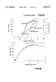
- FIG. 4a is a graph showing (1) continuous wave channel power and modulated output power monitored on an optical spectrum analyzer as a function of channel bias current with single-channel operation of the multi-frequency laser using the experimental set-up of FIG. 2, and (2) mixer output voltage with the relative delay of a LO input signal to the mixer set to obtain maximum correlation using the experimental set-up of FIG. 2;
- FIG. 4b is a graph representing mixer output versus channel output power of the data shown in FIG. 4a;
- FIG. 5 is a graph representing mixer output voltage as a function of channel 3's power as monitored on an optical spectrum analyzer using the experimental set-up of FIG. 2;
- FIG. 6a depicts a total output signal of the multi-frequency laser in the experimental set-up of FIG. 2 with non-return-to-zero modulation of all 8-channels simultaneously;
- FIG. 6b depicts a non-return-to-zero eye pattern of one channel of the multi-frequency laser in the experimental set-up of FIG. 2 filtered by an 8-channel arrayed waveguide grating router;
- FIG. 6c depicts a total output signal of the multi-frequency laser in the experimental set-up of FIG. 2 using sequential return-to-zero modulation
- FIG. 6d depicts a sequentially return-to-zero modulated eye pattern of one channel of the multi-frequency laser in the experimental set-up of FIG. 2 filtered by the 8-channel arrayed waveguide grating router.
- stabilization and equalization ofeach channel of a multi-channel transmitter may be based on adjusting the ⁇ 0 ⁇ current (I ⁇ 0 ⁇ ) or ⁇ 1 ⁇ current (I ⁇ 1 ⁇ ) levels, bias current, modulation current, or any combination thereof. Since all such adjustmentsare generally performed in a similar manner, the process will only be described, by way of illustrative example, with regard to stabilization based on the bias current.
- a multi-channel stabilization system constituted in accordance with a first embodiment of the present invention receives a data stream of N channels from a data source.
- the data stream of N data channels generated from the data source is received by a laser driver 10 which generates N driving signals that control the bias current in each ofthe N channels.
- the laser driver 10 is also capable of controlling modulation current and ⁇ 0 ⁇ and ⁇ 1 ⁇ current levels (I ⁇ 0 ⁇ and I ⁇ 1 ⁇ ).
- the N driving signals are received by a multi-channel transmitter 20, as for example an integrated DFB laser array or MFL, which generates a total power output signal.
- tapping device 40 splits the optical light output from the multi-channel transmitter 20 in some proportional ratio, e.g. 20:80% or any other desired ratio, into two taps or ports. Although two taps or ports are shown in FIG. 1a, it is contemplated that more than two taps or ports may also be used. Moreover, in FIG. 1a, tapping device 40 is shown as separate from the multi-channel transmitter 40; however, tapping device 40 may be integrated with certain multi-channel transmitters. One of the taps or ports of tapping device 40 is connected to a lightwaves system 90 in which the multi-channel transmitter is the optical source.
- a lightwaves system 90 in which the multi-channel transmitter is the optical source.
- An optical to electrical converter 50 such as an optical receiver or photodetector, receives a sample of the total power output signal through the other tap or port of tapping device 40 and converts the optical signal to an output electrical signal. This output electrical signal is used to measure the output power of each channel.
- the N data channels generated by the data source are also received by a selector 30, such as a multiplexer or switching device, which in response to a control signal from a controller 80 sequences through a set of reference data signals associated with each of the N channel data signals and selects a reference data signal associated with a single channel to thereby make that single channel active.
- a correlator 60a correlates the reference data signal output of the selector 30 with the output electricalsignal of converter 50 and generates a correlation voltage proportional to the output power of the active channel.
- Correlator 60a may be, for example, a single RF mixer or high-speed analog multiplier.
- an analog-to-digital converter or voltmeter may be used to convert the output from the correlator from an analog signal to a digital signal when using an analog device as the correlator, e.g. an RF mixer, in conjunction with a digital controller.
- an analog device e.g. an RF mixer
- the need for an analog-to-digital converter may be eliminated by using an analog device as the correlator and an analog controller.
- Controller 80a compares the correlation voltage to a predetermined set-point correlation voltage. If the correlation voltage is not equal to or does not surpass the set-point correlation voltage, then the bias current is adjusted (incremented/decremented) appropriately via a correction signal from the controller 80 to the laser driver 10 and the process is repeated. Otherwise--if the correlation voltage is either equalto or surpasses the set-point correlation voltage--then the channel has reached a nominal operating point and the process stops. If the bias current is adjusted and the correlation voltage surpasses the set-point correlation voltage, then after all of the channels have been sequenced tothereby return to the same channel, the bias current will start at the level prior to surpassing the set-point correlation voltage.
- the bias current for channel i will be incremented and, if the correlation voltage is then 51 mV, the process stops. After all of the N data channels have been stabilized and channel i is once again selected, the bias current for channel i will start at the previous level before the correlation voltage surpassed the set-point correlation voltage and the process is repeated.
- controller 80a When the correlation voltage of a particular channel surpasses or is equal to the set-point correlation voltage, that active channel is nominally equalized; controller 80a then signals selector 30 to sequence through theset of reference data signals to the next reference data signal associated with the next channel, and the process is repeated. Controller 80a continuously sequences through the set of reference data signals, one at atime, by sending a control signal to selector 30, and the correlation feedback process is repeated for each channel during operation of the multi-channel transmitter so that the output power of each of the channelsis equalized. Thus, in accordance with the invention the output power of each channel may be stabilized without having to shut-down the multi-channel transmitter.
- FIG. 1b In a second embodiment, shown in FIG. 1b, stabilization of the channels is performed for each of the N data channels in parallel, instead of sequentially as in the first embodiment shown in FIG. 1a.
- the multi-channel stabilization system of this second embodiment is distinguishable from the first embodiment in that: 1) selector 30 has beeneliminated in the second embodiment so that correlator 60b directly receives the N data channels in parallel; 2) correlator 60b comprises, by way of example, a plurality of RF mixers or a plurality of high-speed analog multipliers, one for each of the N data channels, or a single digital signal processing chip, and generates a plurality of correlation voltages, one for each of the N data channels; and 3) controller 80b generates a plurality of correction signals, one for each of the N data channels.
- the correlation feedback multi-channel stabilization system in accordance with this second embodiment employs the same correlation feedback technique as the first embodiment, the only difference between the embodiments being that in the first embodiment stabilization of the channels is performed sequentially whereas, in the second embodiment, stabilization of all of the N data channels is performed in parallel.
- the correlation feedback system in accordance with either the first or second embodiment of the invention may also be used, when necessary, to correct for inherent offset errors, for example, when using an analog mixer as the correlation device.
- offset errors are measured in one round while sequencing through the channels by disabling (turning off) a single channel at a time and determining the correlation voltage using the reference data signal associated with the disabled channel.
- the controller sends a signal to laser driver 10 to disable a single channel and the correlation voltage is determined.
- the controller Based on the correlation voltage, which represents a measured offset error, the controller generates an offset error signal which is used to compensate for offset errors, via the feedback loop to laser driver 10. Then the next reference data signal is selected, the associated channel is disabled and the offseterror process is repeated until the offset error has been corrected for each channel. This offset error correction process is performed once for each channel.
- longer correlation times may be used to reduce cross-correlation errors, or crosscorrelation errors may be reduced by using binary correlators as for example a Harris Semiconductor HSP45256 Binary Correlator, in order to synthesize real-time corrections to the correlation voltage.
- a nominal bias current and set-point correlation voltage is set depending on the design objective. Stabilization processing is performed on each channel independently by selecting the reference data signal for which stabilization processing is to begin.
- the data stream of N data channels generated by the data source is transmitted to the laser driver and the selector 30.
- Laser driver 10 generates N driving signals, one for each of the N data channels, which are received by the multi-channel transmitter 20 and a total power output signal is generated.A sample of the total power output signal from the multi-channel transmitter 20 is converted from an optical to an electrical signal.
- the output electrical signal from converter 50 and the reference data signal from the selector 30 are correlated and the correlation signal generated is converted to a correlation voltage.
- Controller 80 compares the correlation voltage with the set-point correlation voltage.
- the bias current is adjusted via a correction signal from the controller to the laser driver and the correlation voltage is determined. This process is repeated until a nominal operating point is reached, when the correlation voltage surpasses or is equal to the set-point correlation voltage. Once the nominal operating point of a channel has been reached, the controller sends a control signal to the selector 30 to sequence through to the next reference data signal so that the next channel becomes the active channel. This iterative process is continuously performed during operation of the multi-channel transmitter in order to stabilize each channel's output power. A similar operation is performed using the disclosed second embodiment of the invention the only difference being that the N data channels are not processed sequentially but are instead stabilized in parallel.
- offset errors may be measured by disabling (turning off) the presently active channel and determining the correlation voltage. If the correlation voltage is zero, then no offset error is detected. Otherwise, the correlation voltage represents the measured offset error of the channel.
- the laser driving signal of the channel is adjusted on the basis of the measured offset error, via a feedback loop from the controller. This offset correction process is performed a single time for each channel in order to correct for inherent offset when using an analog mixing device as the correlator.
- the correlation feedback stabilization method and apparatus of the invention is particularly versatile in that both independent random data and broadcast data may be used as the channel data.
- the data In the instance in which broadcast data is used, the data must be decorrelated to ensure thatthe channels will be properly distinguished. Decorrelation of the data may be accomplished by introducing relative time delays, as for example using shift registers, between the channels. Alternatively, or in addition thereto, longer correlation times may be used to differentiate the channels.
- the invention can be used with broadcast data so long as the channel data is sufficiently decorrelated, irrespective of the means by which the data is decorrelated.
- the reference data signals may be simply the channel data signals themselves, or a unique identification code carried as part of each data channel, as for example a header or trailer, may also be used.
- the unique identification codes associated with each of the N data channels may be represented by a matrix, the rows of which form an orthogonal set of vectors corresponding in number to the number of channels in the multi-channel transmitter such that each row is used to identify each of the channels.
- the orthogonal set of eight 8-bit vectors for an 8-channel multi-channel transmitter may be represented by the matrix ##EQU1##
- the array A may be written in bipolar form to clearly show that the inner product of any two rows is zero. Furthermore, the equal density of marks and spaces also ensures that other input noise will average to zero at theoutput of the correlator.
- Use of identification codes provides the additional benefit of simplifying the implementation of correlation feedback in regenerators by locally synthesizing the correlation sequencesrather than having to recover the data from all of the channels.
- the unique identification codes may be a small modulation depth on top of the data stream. It is also contemplated that each channel may be identified using unique audio tones or any other means by which the individual channels may be distinguished.
- An experimental apparatus was used to verify the accuracy of stabilization through correlation feedback in accordance with the invention.
- an integrated 24-channel 1550 nm InGaAsP laser as described in the aforementioned publication by M. Zirngibl, C. H. Joyner and L. W. Stulz, "Demonstration of a 9 ⁇ 200 Mbit/s Wavelength Division Multiplexed Transmitter", Electron. Lett., Vol. 30, p.1484 (1994), was used as the multi-frequency laser 20'.
- the InGaAsP laser included an arrayed-waveguide router with gain sections on each of the 24 channel ports and a single common amplifier on the output port.
- the laser was packaged with a thermo-electric cooler and connectorized with a lensedfiber pigtail. Only 8 laser channels were operated with 200 GHz channel spacing (approximately 1548 to 1559.5 nm wavelength range) and each of the8 gain sections was biased in the nominal range of 50 to 80 mA.
- the modulation signals approximately 40 mA peak-to-peak, were AC-coupled through bias tees. Each channel was modulated with 50 Mb/s, 1 Kbit length random strings created from a random number generator using different seednumbers for each channel. Broadcast data was also tested by copying the same data pattern into all channels and shifting successive channels by 1 bit (20 ns) in order to decorrelate the data.
- the total fiber-coupled output power from the laser was approximately -10 dBm with NRZ modulation (-13 dBm with sequential RZ) andwas divided through a 20:80% fiber-splitter 40' with the output from the 80% tap connected to an optical receiver 50' used for the feedback loop.
- the output electrical signal of the optical receiver 50' was connected to the RF input of a 10 MHz bandwidth RF electrical mixer 60'. A 10 MHz bandwidth was sufficient here to obtain correlation measurements on 50 Mb/s data.
- the RF mixer's LO input was connected to one channel of a multi-channel modulation source 30'; the mixer's IF output was connected to a voltmeter 70'.
- the output of the voltmeter was proportional to the correlation of the laser output power P total (t) and the LO input signal V LOJ (t) where j designates the selected channel.
- the mixer output is given by the equation
- K is a scale factor
- P cw is the continuous wave output power, which includes amplified spontaneous emission and unmodulated channel power
- ⁇ P i (t) represents the summation of each channels' output power
- P i (t), P j (t) represent the output power of different channels
- i, j designates two separate selected channels.
- V mix is proportional to the modulated signal power in channel j.
- FIG. 3 The relative timing of the LO and RF input voltages to the RF mixer were adjusted to obtain the maximum output signal as shown in FIG. 3. This measurement was obtained with the laser operating on a single NRZ channel and mixing the received signal with a delayed replica of the data.
- the curve shown in FIG. 3 is typical of an autocorrelation function of random data; the response is maximum where the input signals to the mixer are bitsynchronized and approaches zero when the delay is advanced or retarded by more than one bit period.
- FIG. 3 also illustrates the principle of decorrelating the broadcast data.
- FIG. 4a shows measured L-I curves of the optical output power in the 20% port of the fiber-splitter versus DC laser bias with the MFL operating in a single channel.
- the common output amplifier was biased at 150 mA. These measurements were taken with continuous wave and NRZ modulated laser conditions. Also shown is the mixer output when the delay of the Lo signalto the mixer was set to obtain the maximum correlation.
- the continuous wavelasing threshold was approximately 50 mA; the apparent threshold under modulation was 30 mA as the modulation current of 40 mA peak-to-peak was AC coupled through the bias tee. Above 70 mA DC bias, the modulated L-I curve slope efficiency sharply increased as the ⁇ 0 ⁇ level went above threshold. Near this same bias condition the mixer output leveled off and then declined due to laser saturation.
- FIG. 4b represents the mixer output versus channel output power and clearlyshows the saturation of the mixer output once the ⁇ 0 ⁇ level bias reaches the laser threshold. Saturation of the mixer output is a useful signature for identifying the optimum operating currents for the MFL channels.
- the mixer output for channel 3 was measured with interference from the other 7 channels also modulated with random 50 Mb/s NRZ data. Each channel was programmed with a different random sequence to minimize their cross-correlation.
- a linear autocorrelation response was achieved, as shown in FIG. 5 which representsthe mixer output versus channel 3 power.
- the measurement was obtained by changing the DC bias current to channel 3 after setting the 8 channels to have equal output power at the nominal operating point where the channel 3bias current (I bias 3) was 56 mA.
- the linear response curve confirms that the mixer output voltage is a valid measure of optical signal power in a single modulated channel in the presence of interfering channels.
- the mixer voltages of all channels stabilized to within 5% of the set-point value after seven iterations of adjusting the currents to each of the eight channels.
- the average adjustment period for each channel was 3.7 sec., limited by the speed of the computer control interface. Use of a dedicated controller could reducethis time to an average period of the correlation measurement of approximately 200 msec.
- Offset errors in the mixer output voltages due to cross-correlations among the channels were measured by turning off the active channel after the channels were nominally equalized, and the measured offset error was then used to correct the mixer voltages once all channels were turned on again.
- Table 1 summarizes the offset voltages with independent NRZ data channels and the steady-state, normalized channel powers measured when cycling the MFL from between 15° C. and 20° C.
- the set-point mixer voltage is 40 mV.
- the results of Table 1 show that good uniformity in channel power was obtained--that is, temperature changes of 5° C. produced fluctuations in power of less than 1 dB and the maximum power difference among all eight channels was 1.23 dB. Similar experimental results were obtained using broadcast NRZ data in which the maximum power difference among all eight channels was 0.74 dB.
- the correlation feedback control loop of the present invention compensates for temperature-induced fluctuations or changes in the output power of the MFL. Without the control loop, greater than 10 dB excursions in channel power were observed over small changes intemperature of 5° C. However, in this software-implemented control loop, the maximum allowable temperature slew rate was less than 4° C./min because of the slow cycling of the control sequence. This was tested by first adjusting the laser temperature controller from 15°C. to 20° C. at a slew rate of 25° C./min, and then from 20° C. to 15° C. at a slew rate of -4° C./min, and observing the power excursions in each channel. The observed power fluctuations are summarized below in Table 3. As seen from the results in Table 3, at the lower slew rate of -4° C./min the power variations were limited to within 2.5 dB, whereas variations greater than 7 dB were observed at the higher slew rate of 25° C./min.
- Output eye patterns and bit-error-rate performance were tested with the NRZand sequential RZ modulation of the 8 channels during stabilization by correlation feedback.
- the output eye patterns and bit-error-rate performance results were generated by sending the signal at the 20% port of the fiber-splitter40' through an erbidium-doped fiber amplifier (EDFA) 90'.
- the output from EDFA 90' was filtered by an array waveguide grating router (AWGR) 100', thereby generating a single channel eye pattern.
- the single channel eye pattern was transmitted to an optical spectrum analyzer (OSA)/bit-error-rate receiver (BER Rx) 1101 to measure the modulated output power and bit-error-rate performance.
- OSA optical spectrum analyzer
- BER Rx bit-error-rate receiver
- FIGS. 6a through 6d show the MFL output and eye patterns detected with a 400 MHz bandwidth receiver.
- FIG. 6a shows the total output signal from the MFL during NRZ modulation
- FIG. 6b shows a representative eye pattern of one channel filtered by the AWGR.
- Significant turn-on delay due to below-threshold operation and distortion due to crosstalk in the common amplifier were evident, as seen in FIG. 6b.
- the MFL output signal with sequential RZ modulation is shown in FIG. 6c and a representative signal-channel eye pattern filtered by the AWGR is shown in FIG. 6d.
- FIG. 6d In contrast to that shown in FIG. 6b, no significant interchannel crosstalk was observed using sequential RZ modulation while the power differences inFIG. 6c were caused by timing errors encountered during NRZ modulation.
Abstract
Description
V.sub.mix =K×AVG V.sub.LOJ (t)×P.sub.total (t)!
P.sub.total (t)=P.sub.cw +Σ P.sub.i (t)
AVG P.sub.i (t)×P.sub.j (t)!=0 for ≠j
              TABLE 1
______________________________________
Relative Channel-To-Channel Power Variation with
Independent NRZ Data
Wavelength
        V.sub.offset
                P@15° C.
                         P@20° C.
                                P@15° C.
                                       →P@20° C.
No.     (mV)    (dB)→
                         (dB)→
                                (dB)→
                                       (dB)
______________________________________
1       16.89   0.83     0      1.06   0.14
2       4.98    0.71     0.83   0.77   0.49
3       19.24   0.76     1.06   1.03   0.47
4       20.07   1.21     0.43   1.13   0.66
5       15.53   0.71     0.23   0.50   0.57
6       12.44   1.21     0.72   1.05   1.15
7       12.58   0.20     0.49   1.28   1.25
8       22.07   0.63     1.23   0.79   0.81
______________________________________
              TABLE 2
______________________________________
Relative Channel-To-Channel Power Variation with
Sequential RZ Modulated Data
Wavelength No.
          V.sub.offset (mV)
                     P@16° C. (dB)
                                 P@20° C. (dB)
______________________________________
1         4.5        1.38        1.04
2         4.8        1.43        2.10
3         5.3        1.09        1.17
4         4.7        0.79        1.41
5         5.1        0.55        1.32
6         5.3        -0.68       0.28
7         5.4        1.32        1.33
8         5.4        -2.87       0
______________________________________
              TABLE 3
______________________________________
Temperature Induced Channel Power Fluctuations
             Power Variation
                          Power Variation
Wavelength No.
             @-4° C./min (dB)
                          @25° C./min (dB)
______________________________________
1            1.68         4.39
2            1.45         3.23
3            0.94         4.90
4            1.72         4.14
5            2.34         7.06
6            2.46         4.19
7            2.24         4.22
8            1.97         5.48
______________________________________
Claims (21)
Priority Applications (1)
| Application Number | Priority Date | Filing Date | Title |
|---|---|---|---|
| US08/729,934 US5745275A (en) | 1996-10-15 | 1996-10-15 | Multi-channel stabilization of a multi-channel transmitter through correlation feedback |
Applications Claiming Priority (1)
| Application Number | Priority Date | Filing Date | Title |
|---|---|---|---|
| US08/729,934 US5745275A (en) | 1996-10-15 | 1996-10-15 | Multi-channel stabilization of a multi-channel transmitter through correlation feedback |
Publications (1)
| Publication Number | Publication Date |
|---|---|
| US5745275A true US5745275A (en) | 1998-04-28 |
Family
ID=24933206
Family Applications (1)
| Application Number | Title | Priority Date | Filing Date |
|---|---|---|---|
| US08/729,934 Expired - Lifetime US5745275A (en) | 1996-10-15 | 1996-10-15 | Multi-channel stabilization of a multi-channel transmitter through correlation feedback |
Country Status (1)
| Country | Link |
|---|---|
| US (1) | US5745275A (en) |
Cited By (41)
| Publication number | Priority date | Publication date | Assignee | Title |
|---|---|---|---|---|
| US5917623A (en) * | 1997-05-22 | 1999-06-29 | Nec Corporation | Wavelength division multiplexing systems |
| US6031647A (en) * | 1996-10-23 | 2000-02-29 | Nortel Networks Corporation | Stable power control for optical transmission systems |
| US6040933A (en) * | 1997-12-19 | 2000-03-21 | Nortel Networks Corporation | Method and apparatus for channel equalization in wavelength division multiplexed systems |
| US6043915A (en) * | 1997-03-31 | 2000-03-28 | Lucent Technologies Inc. | Stabilization of a multi-channel optical signal transmitter through correlation feedback |
| US6178026B1 (en) * | 1997-06-02 | 2001-01-23 | Nec Corporation | Analog optical transmission apparatus |
| US6252692B1 (en) * | 1996-06-07 | 2001-06-26 | Nortel Networks Limited | Optical fibre transmission systems |
| US6275516B1 (en) * | 1998-07-02 | 2001-08-14 | Agere Systems Optoelectronics Guardian Corp. | Article for detecting power drift in the putout of a diode array source |
| US6304350B1 (en) * | 1997-05-27 | 2001-10-16 | Lucent Technologies Inc | Temperature compensated multi-channel, wavelength-division-multiplexed passive optical network |
| EP1176714A2 (en) * | 2000-06-28 | 2002-01-30 | TRW Inc. | Analog power control system for a multi-carrier transmitter |
| EP1176734A2 (en) * | 2000-06-28 | 2002-01-30 | TRW Inc. | Digital power control system for a multi-carrier transmitter |
| US6351583B1 (en) | 2000-01-28 | 2002-02-26 | Agere Systems Guardian Corp. | Multiple laser wavelength stabilization |
| US6369923B1 (en) * | 1999-09-07 | 2002-04-09 | Cinta Corporation | Multiwavelength stabilization with a single reference comb filter in DWDM systems |
| US6421151B1 (en) * | 1997-08-13 | 2002-07-16 | Lucent Technologies Inc. | Method and arrangement for stabilizing wavelength of multi-channel optical transmission systems |
| WO2002079837A1 (en) * | 2001-03-28 | 2002-10-10 | Prima Luci, Inc. | All optical multiplexer |
| US6501773B1 (en) * | 2000-06-19 | 2002-12-31 | Versatile Optical Networks, Inc. | Stabilization of a laser array module |
| GB2377838A (en) * | 2001-07-21 | 2003-01-22 | Zarlink Semiconductor Ab | Programmable EPROM controller for optical transmitter array |
| EP1283570A1 (en) * | 2000-04-19 | 2003-02-12 | Fujitsu Limited | Parallel optical module and information processing device |
| US6577399B1 (en) | 2000-03-24 | 2003-06-10 | Triquing Technology Holding Co. | Optical waveguide based power and wavelength monitor |
| US6708003B1 (en) * | 1999-12-16 | 2004-03-16 | Northrop Grumman Corporation | Optical energy transmission system utilizing precise phase and amplitude control |
| US20040131366A1 (en) * | 2000-03-16 | 2004-07-08 | Hideaki Tsushima | Wavelength tunable optical transmitter, optical transponder and optical transmission system |
| US20070003281A1 (en) * | 2005-06-30 | 2007-01-04 | Infinera Corporation | Active control loop for power control of optical channel groups |
| US20070174062A1 (en) * | 2006-01-20 | 2007-07-26 | Microsoft Corporation | Complex-transform channel coding with extended-band frequency coding |
| US20070172071A1 (en) * | 2006-01-20 | 2007-07-26 | Microsoft Corporation | Complex transforms for multi-channel audio |
| US20070174063A1 (en) * | 2006-01-20 | 2007-07-26 | Microsoft Corporation | Shape and scale parameters for extended-band frequency coding |
| US20070185706A1 (en) * | 2001-12-14 | 2007-08-09 | Microsoft Corporation | Quality improvement techniques in an audio encoder |
| US20080221908A1 (en) * | 2002-09-04 | 2008-09-11 | Microsoft Corporation | Multi-channel audio encoding and decoding |
| US20090083046A1 (en) * | 2004-01-23 | 2009-03-26 | Microsoft Corporation | Efficient coding of digital media spectral data using wide-sense perceptual similarity |
| US8645146B2 (en) | 2007-06-29 | 2014-02-04 | Microsoft Corporation | Bitstream syntax for multi-process audio decoding |
| US20140099116A1 (en) * | 2012-10-08 | 2014-04-10 | Futurewei Technologies, Inc. | Resource-Efficient Digital Chromatic Dispersioin Compensation in Fiber Optical Communication Using Spectral-Shaping Subcarrier Modulation |
| US20140186056A1 (en) * | 2011-12-02 | 2014-07-03 | Semtech Corporation | Closed Loop Optical Modulation Amplitude Control |
| US9264533B2 (en) | 2000-01-07 | 2016-02-16 | Tq Delta, Llc | Systems and methods for establishing a diagnostic transmission mode and communicating over the same |
| US9286251B2 (en) | 2004-10-12 | 2016-03-15 | Tq Delta, Llc | Resource sharing in a telecommunications environment |
| US9300601B2 (en) | 2001-10-05 | 2016-03-29 | Tq Delta, Llc | Bonding device and method |
| US9300324B2 (en) | 2004-09-25 | 2016-03-29 | Tq Delta, Llc | CRC counter normalization |
| US9485055B2 (en) | 2006-04-12 | 2016-11-01 | Tq Delta, Llc | Packet retransmission and memory sharing |
| US9485128B2 (en) | 1999-11-09 | 2016-11-01 | Tq Delta, Llc | System and method for scrambling using a bit scrambler and a phase scrambler |
| US9521003B2 (en) | 1998-01-26 | 2016-12-13 | Tq Delta, Llc | Multicarrier transmission system with low power sleep mode and rapid-on capability |
| US9621198B2 (en) | 2004-10-15 | 2017-04-11 | Tq Delta, Llc | DMT symbol repetition in the presence of impulse noise |
| US9768865B2 (en) * | 2014-10-15 | 2017-09-19 | Infinera Corporation | Arbitrary wavelocking of an optical transmitter using embedded data sequences |
| CN109964412A (en) * | 2016-11-15 | 2019-07-02 | 华为技术有限公司 | A kind of multipath correction device, amplitude correction method, method for correcting phase, receive-transmit system and base station |
| US10567112B2 (en) | 2004-03-03 | 2020-02-18 | Tq Delta, Llc | Impulse noise management |
Citations (1)
| Publication number | Priority date | Publication date | Assignee | Title |
|---|---|---|---|---|
| US5387992A (en) * | 1992-10-15 | 1995-02-07 | Kokusai Denshin Denwa Kabushiki Kaisha | Optical frequency multiplex carrier control system |
-
1996
- 1996-10-15 US US08/729,934 patent/US5745275A/en not_active Expired - Lifetime
Patent Citations (1)
| Publication number | Priority date | Publication date | Assignee | Title |
|---|---|---|---|---|
| US5387992A (en) * | 1992-10-15 | 1995-02-07 | Kokusai Denshin Denwa Kabushiki Kaisha | Optical frequency multiplex carrier control system |
Cited By (100)
| Publication number | Priority date | Publication date | Assignee | Title |
|---|---|---|---|---|
| US6252692B1 (en) * | 1996-06-07 | 2001-06-26 | Nortel Networks Limited | Optical fibre transmission systems |
| US6031647A (en) * | 1996-10-23 | 2000-02-29 | Nortel Networks Corporation | Stable power control for optical transmission systems |
| US6043915A (en) * | 1997-03-31 | 2000-03-28 | Lucent Technologies Inc. | Stabilization of a multi-channel optical signal transmitter through correlation feedback |
| US5917623A (en) * | 1997-05-22 | 1999-06-29 | Nec Corporation | Wavelength division multiplexing systems |
| US6304350B1 (en) * | 1997-05-27 | 2001-10-16 | Lucent Technologies Inc | Temperature compensated multi-channel, wavelength-division-multiplexed passive optical network |
| US6178026B1 (en) * | 1997-06-02 | 2001-01-23 | Nec Corporation | Analog optical transmission apparatus |
| US6421151B1 (en) * | 1997-08-13 | 2002-07-16 | Lucent Technologies Inc. | Method and arrangement for stabilizing wavelength of multi-channel optical transmission systems |
| US6040933A (en) * | 1997-12-19 | 2000-03-21 | Nortel Networks Corporation | Method and apparatus for channel equalization in wavelength division multiplexed systems |
| US9521003B2 (en) | 1998-01-26 | 2016-12-13 | Tq Delta, Llc | Multicarrier transmission system with low power sleep mode and rapid-on capability |
| US6275516B1 (en) * | 1998-07-02 | 2001-08-14 | Agere Systems Optoelectronics Guardian Corp. | Article for detecting power drift in the putout of a diode array source |
| US6369923B1 (en) * | 1999-09-07 | 2002-04-09 | Cinta Corporation | Multiwavelength stabilization with a single reference comb filter in DWDM systems |
| US9755876B2 (en) | 1999-11-09 | 2017-09-05 | Tq Delta, Llc | System and method for scrambling the phase of the carriers in a multicarrier communications system |
| US9485128B2 (en) | 1999-11-09 | 2016-11-01 | Tq Delta, Llc | System and method for scrambling using a bit scrambler and a phase scrambler |
| US10187240B2 (en) | 1999-11-09 | 2019-01-22 | Tq Delta, Llc | System and method for scrambling the phase of the carriers in a multicarrier communications system |
| US6708003B1 (en) * | 1999-12-16 | 2004-03-16 | Northrop Grumman Corporation | Optical energy transmission system utilizing precise phase and amplitude control |
| US9838531B2 (en) | 2000-01-07 | 2017-12-05 | Tq Delta, Llc | Systems and methods for establishing a diagnostic transmission mode and communicating over the same |
| US10623559B2 (en) | 2000-01-07 | 2020-04-14 | Tq Delta, Llc | Systems and methods for establishing a diagnostic transmission mode and communicating over the same |
| US9264533B2 (en) | 2000-01-07 | 2016-02-16 | Tq Delta, Llc | Systems and methods for establishing a diagnostic transmission mode and communicating over the same |
| US9973624B2 (en) | 2000-01-07 | 2018-05-15 | Tq Delta, Llc | Systems and methods for establishing a diagnostic transmission mode and communicating over the same |
| US9319512B2 (en) | 2000-01-07 | 2016-04-19 | Tq Delta, Llc | Systems and methods for establishing a diagnostic transmission mode and communicating over the same |
| US9479637B2 (en) | 2000-01-07 | 2016-10-25 | Tq Delta, Llc | Systems and methods for establishing a diagnostic transmission mode and communicating over the same |
| US10264119B2 (en) | 2000-01-07 | 2019-04-16 | Tq Delta, Llc | Systems and methods for establishing a diagnostic transmission mode and communicating over the same |
| US6351583B1 (en) | 2000-01-28 | 2002-02-26 | Agere Systems Guardian Corp. | Multiple laser wavelength stabilization |
| US20040131366A1 (en) * | 2000-03-16 | 2004-07-08 | Hideaki Tsushima | Wavelength tunable optical transmitter, optical transponder and optical transmission system |
| US6577399B1 (en) | 2000-03-24 | 2003-06-10 | Triquing Technology Holding Co. | Optical waveguide based power and wavelength monitor |
| EP1283570A4 (en) * | 2000-04-19 | 2006-07-05 | Fujitsu Ltd | Parallel optical module and information processing device |
| EP1283570A1 (en) * | 2000-04-19 | 2003-02-12 | Fujitsu Limited | Parallel optical module and information processing device |
| US6501773B1 (en) * | 2000-06-19 | 2002-12-31 | Versatile Optical Networks, Inc. | Stabilization of a laser array module |
| EP1176714A3 (en) * | 2000-06-28 | 2003-11-05 | TRW Inc. | Analog power control system for a multi-carrier transmitter |
| EP1176734A3 (en) * | 2000-06-28 | 2003-11-05 | TRW Inc. | Digital power control system for a multi-carrier transmitter |
| EP1176734A2 (en) * | 2000-06-28 | 2002-01-30 | TRW Inc. | Digital power control system for a multi-carrier transmitter |
| EP1176714A2 (en) * | 2000-06-28 | 2002-01-30 | TRW Inc. | Analog power control system for a multi-carrier transmitter |
| US7174069B2 (en) | 2001-03-28 | 2007-02-06 | Main Street Ventures Llc | All optical multiplexer |
| US20040184804A1 (en) * | 2001-03-28 | 2004-09-23 | Arie Shahar | All optical multiplexer |
| WO2002079837A1 (en) * | 2001-03-28 | 2002-10-10 | Prima Luci, Inc. | All optical multiplexer |
| US20030025972A1 (en) * | 2001-07-21 | 2003-02-06 | Zarlink Semiconductor Ab | Multi-channel laser driver with individually programmable channels |
| GB2377838A (en) * | 2001-07-21 | 2003-01-22 | Zarlink Semiconductor Ab | Programmable EPROM controller for optical transmitter array |
| US9894014B2 (en) | 2001-10-05 | 2018-02-13 | Tq Delta, Llc | Bonding device and method |
| US10341261B2 (en) | 2001-10-05 | 2019-07-02 | Tq Delta, Llc | Bonding device and method |
| US9300601B2 (en) | 2001-10-05 | 2016-03-29 | Tq Delta, Llc | Bonding device and method |
| US8554569B2 (en) | 2001-12-14 | 2013-10-08 | Microsoft Corporation | Quality improvement techniques in an audio encoder |
| US7917369B2 (en) | 2001-12-14 | 2011-03-29 | Microsoft Corporation | Quality improvement techniques in an audio encoder |
| US20070185706A1 (en) * | 2001-12-14 | 2007-08-09 | Microsoft Corporation | Quality improvement techniques in an audio encoder |
| US20090326962A1 (en) * | 2001-12-14 | 2009-12-31 | Microsoft Corporation | Quality improvement techniques in an audio encoder |
| US9443525B2 (en) | 2001-12-14 | 2016-09-13 | Microsoft Technology Licensing, Llc | Quality improvement techniques in an audio encoder |
| US8805696B2 (en) | 2001-12-14 | 2014-08-12 | Microsoft Corporation | Quality improvement techniques in an audio encoder |
| US7860720B2 (en) | 2002-09-04 | 2010-12-28 | Microsoft Corporation | Multi-channel audio encoding and decoding with different window configurations |
| US20080221908A1 (en) * | 2002-09-04 | 2008-09-11 | Microsoft Corporation | Multi-channel audio encoding and decoding |
| US8620674B2 (en) | 2002-09-04 | 2013-12-31 | Microsoft Corporation | Multi-channel audio encoding and decoding |
| US20110060597A1 (en) * | 2002-09-04 | 2011-03-10 | Microsoft Corporation | Multi-channel audio encoding and decoding |
| US8386269B2 (en) | 2002-09-04 | 2013-02-26 | Microsoft Corporation | Multi-channel audio encoding and decoding |
| US8069050B2 (en) | 2002-09-04 | 2011-11-29 | Microsoft Corporation | Multi-channel audio encoding and decoding |
| US8099292B2 (en) | 2002-09-04 | 2012-01-17 | Microsoft Corporation | Multi-channel audio encoding and decoding |
| US8255230B2 (en) | 2002-09-04 | 2012-08-28 | Microsoft Corporation | Multi-channel audio encoding and decoding |
| US20110054916A1 (en) * | 2002-09-04 | 2011-03-03 | Microsoft Corporation | Multi-channel audio encoding and decoding |
| US20090083046A1 (en) * | 2004-01-23 | 2009-03-26 | Microsoft Corporation | Efficient coding of digital media spectral data using wide-sense perceptual similarity |
| US8645127B2 (en) | 2004-01-23 | 2014-02-04 | Microsoft Corporation | Efficient coding of digital media spectral data using wide-sense perceptual similarity |
| US10805040B2 (en) | 2004-03-03 | 2020-10-13 | Tq Delta, Llc | Impulse noise management |
| US10567112B2 (en) | 2004-03-03 | 2020-02-18 | Tq Delta, Llc | Impulse noise management |
| US11005591B2 (en) | 2004-03-03 | 2021-05-11 | Tq Delta, Llc | Impulse noise management |
| US10049003B2 (en) | 2004-09-25 | 2018-08-14 | Tq Delta, Llc | CRC counter normalization |
| US10346243B2 (en) | 2004-09-25 | 2019-07-09 | Tq Delta, Llc | CRC counter normalization |
| US9300324B2 (en) | 2004-09-25 | 2016-03-29 | Tq Delta, Llc | CRC counter normalization |
| US9898220B2 (en) | 2004-10-12 | 2018-02-20 | Tq Delta, Llc | Resource sharing in a telecommunications environment |
| US10409510B2 (en) | 2004-10-12 | 2019-09-10 | Tq Delta, Llc | Resource sharing in a telecommunications environment |
| US11010073B2 (en) | 2004-10-12 | 2021-05-18 | Tq Delta, Llc | Resource sharing in a telecommunications environment |
| US9286251B2 (en) | 2004-10-12 | 2016-03-15 | Tq Delta, Llc | Resource sharing in a telecommunications environment |
| US10579291B2 (en) | 2004-10-12 | 2020-03-03 | Tq Delta, Llc | Resource sharing in a telecommunications environment |
| US11543979B2 (en) | 2004-10-12 | 2023-01-03 | Tq Delta, Llc | Resource sharing in a telecommunications environment |
| US9547608B2 (en) | 2004-10-12 | 2017-01-17 | Tq Delta, Llc | Resource sharing in a telecommunications environment |
| US11394485B2 (en) | 2004-10-15 | 2022-07-19 | Tq Delta, Llc | DMT symbol repetition in the presence of impulse noise |
| US9621198B2 (en) | 2004-10-15 | 2017-04-11 | Tq Delta, Llc | DMT symbol repetition in the presence of impulse noise |
| US8064771B2 (en) * | 2005-06-30 | 2011-11-22 | Infinera Corporation | Active control loop for power control of optical channel groups |
| US20070003281A1 (en) * | 2005-06-30 | 2007-01-04 | Infinera Corporation | Active control loop for power control of optical channel groups |
| US20070174062A1 (en) * | 2006-01-20 | 2007-07-26 | Microsoft Corporation | Complex-transform channel coding with extended-band frequency coding |
| US20110035226A1 (en) * | 2006-01-20 | 2011-02-10 | Microsoft Corporation | Complex-transform channel coding with extended-band frequency coding |
| US7953604B2 (en) | 2006-01-20 | 2011-05-31 | Microsoft Corporation | Shape and scale parameters for extended-band frequency coding |
| US8190425B2 (en) * | 2006-01-20 | 2012-05-29 | Microsoft Corporation | Complex cross-correlation parameters for multi-channel audio |
| US20070174063A1 (en) * | 2006-01-20 | 2007-07-26 | Microsoft Corporation | Shape and scale parameters for extended-band frequency coding |
| US9105271B2 (en) | 2006-01-20 | 2015-08-11 | Microsoft Technology Licensing, Llc | Complex-transform channel coding with extended-band frequency coding |
| US7831434B2 (en) | 2006-01-20 | 2010-11-09 | Microsoft Corporation | Complex-transform channel coding with extended-band frequency coding |
| US20070172071A1 (en) * | 2006-01-20 | 2007-07-26 | Microsoft Corporation | Complex transforms for multi-channel audio |
| US10484140B2 (en) | 2006-04-12 | 2019-11-19 | Tq Delta, Llc | Packet retransmission and memory sharing |
| US10044473B2 (en) | 2006-04-12 | 2018-08-07 | Tq Delta, Llc | Packet retransmission and memory sharing |
| US9749235B2 (en) | 2006-04-12 | 2017-08-29 | Tq Delta, Llc | Packet retransmission |
| US9485055B2 (en) | 2006-04-12 | 2016-11-01 | Tq Delta, Llc | Packet retransmission and memory sharing |
| US11362765B2 (en) | 2006-04-12 | 2022-06-14 | Tq Delta, Llc | Packet retransmission using one or more delay requirements |
| US11290216B2 (en) | 2006-04-12 | 2022-03-29 | Tq Delta, Llc | Packet retransmission and memory sharing |
| US10498495B2 (en) | 2006-04-12 | 2019-12-03 | Tq Delta, Llc | Packet retransmission |
| US10833809B2 (en) | 2006-04-12 | 2020-11-10 | Tq Delta, Llc | Techniques for packet and message communication in a multicarrier transceiver environment |
| US8645146B2 (en) | 2007-06-29 | 2014-02-04 | Microsoft Corporation | Bitstream syntax for multi-process audio decoding |
| US9026452B2 (en) | 2007-06-29 | 2015-05-05 | Microsoft Technology Licensing, Llc | Bitstream syntax for multi-process audio decoding |
| US9741354B2 (en) | 2007-06-29 | 2017-08-22 | Microsoft Technology Licensing, Llc | Bitstream syntax for multi-process audio decoding |
| US9349376B2 (en) | 2007-06-29 | 2016-05-24 | Microsoft Technology Licensing, Llc | Bitstream syntax for multi-process audio decoding |
| US20140186056A1 (en) * | 2011-12-02 | 2014-07-03 | Semtech Corporation | Closed Loop Optical Modulation Amplitude Control |
| US9300405B2 (en) * | 2011-12-02 | 2016-03-29 | Semtech Corporation | Closed loop optical modulation amplitude control |
| US9112608B2 (en) * | 2012-10-08 | 2015-08-18 | Futurewei Technologies, Inc. | Resource-efficient digital chromatic dispersion compensation in fiber optical communication using spectral shaping subcarrier modulation |
| US20140099116A1 (en) * | 2012-10-08 | 2014-04-10 | Futurewei Technologies, Inc. | Resource-Efficient Digital Chromatic Dispersioin Compensation in Fiber Optical Communication Using Spectral-Shaping Subcarrier Modulation |
| US9768865B2 (en) * | 2014-10-15 | 2017-09-19 | Infinera Corporation | Arbitrary wavelocking of an optical transmitter using embedded data sequences |
| CN109964412A (en) * | 2016-11-15 | 2019-07-02 | 华为技术有限公司 | A kind of multipath correction device, amplitude correction method, method for correcting phase, receive-transmit system and base station |
Similar Documents
| Publication | Publication Date | Title |
|---|---|---|
| US5745275A (en) | Multi-channel stabilization of a multi-channel transmitter through correlation feedback | |
| US6043915A (en) | Stabilization of a multi-channel optical signal transmitter through correlation feedback | |
| US6735395B1 (en) | WDM communication system utilizing WDM optical sources with stabilized wavelengths and light intensity and method for stabilization thereof | |
| US8155488B2 (en) | Wavelength locking and power control systems for multi-channel photonic integrated circuits (PICs) | |
| US6421151B1 (en) | Method and arrangement for stabilizing wavelength of multi-channel optical transmission systems | |
| CA2612165C (en) | Wavelength locking and power control systems for multi-channel photonic integrated circuits (pics) | |
| US9008515B2 (en) | Direct laser modulation | |
| KR20050040149A (en) | Optical signal transmitter with reflective gain clamped semiconductor optical amplifier and optical communicating system using thereof | |
| US20040032643A1 (en) | Method and system for precision cross-talk cancellation in optical amplifiers | |
| US7853155B2 (en) | Method for adjusting bias in optical transmitter with external modulator | |
| US20110158651A1 (en) | Method and apparatus for filtering locking | |
| CN112385158B (en) | Multi-laser wavelength control system and method | |
| US20030030876A1 (en) | Optical transmitter, optical receiver and light wavelength multiplexing system | |
| JPH09214427A (en) | Method for reducing influence of optical beat interruption and optical wave signal transmission system | |
| JPH07199251A (en) | Optical frequency controller | |
| US7212747B2 (en) | Optical transmission device and optical transmission method for transmitting a burst radio signal | |
| US6865015B2 (en) | Method and transmission system for optimization of the transmission characteristics of an optical wavelength division multiplex system | |
| KR20070115006A (en) | Injection locking type light source which of the noise can be minimized | |
| Bell et al. | A/D conversion of microwave signals using a hybrid optical/electronic technique | |
| US6781747B2 (en) | Method for the amplification of wavelength division multiplex (WDM) signals in a WDM transmission system, as well as optical amplifier, optical amplifier system and WDM transmission system for it | |
| US6885462B2 (en) | Wavelength monitoring device and method of tunable laser sources | |
| US8089381B2 (en) | Photonic D/A | |
| US11309973B2 (en) | Optical burst monitoring | |
| EP0622913B1 (en) | Optical transmission apparatus with a directly modulated emitter and an optical filtering before the receiver | |
| Giles et al. | Multichannel stabilization of an integrated WDM laser transmitter through correlation feedback |
Legal Events
| Date | Code | Title | Description |
|---|---|---|---|
| AS | Assignment |
Owner name: LUCENT TECHNOLOGIES INC., NEW JERSEY Free format text: ASSIGNMENT OF ASSIGNORS INTEREST;ASSIGNORS:GILES, CLINTON RANDY;ZIRNGIBL, MARTIN;REEL/FRAME:008532/0316;SIGNING DATES FROM 19970415 TO 19970416 |
|
| FEPP | Fee payment procedure |
Free format text: PAYOR NUMBER ASSIGNED (ORIGINAL EVENT CODE: ASPN); ENTITY STATUS OF PATENT OWNER: LARGE ENTITY |
|
| STCF | Information on status: patent grant |
Free format text: PATENTED CASE |
|
| AS | Assignment |
Owner name: THE CHASE MANHATTAN BANK, AS COLLATERAL AGENT, TEX Free format text: CONDITIONAL ASSIGNMENT OF AND SECURITY INTEREST IN PATENT RIGHTS;ASSIGNOR:LUCENT TECHNOLOGIES INC. (DE CORPORATION);REEL/FRAME:011722/0048 Effective date: 20010222 |
|
| FPAY | Fee payment |
Year of fee payment: 4 |
|
| FPAY | Fee payment |
Year of fee payment: 8 |
|
| AS | Assignment |
Owner name: LUCENT TECHNOLOGIES INC., NEW JERSEY Free format text: TERMINATION AND RELEASE OF SECURITY INTEREST IN PATENT RIGHTS;ASSIGNOR:JPMORGAN CHASE BANK, N.A. (FORMERLY KNOWN AS THE CHASE MANHATTAN BANK), AS ADMINISTRATIVE AGENT;REEL/FRAME:018584/0446 Effective date: 20061130 |
|
| FPAY | Fee payment |
Year of fee payment: 12 |