US5746793A - Reinforced ceramic air bag filters - Google Patents
Reinforced ceramic air bag filters Download PDFInfo
- Publication number
- US5746793A US5746793A US08/586,044 US58604496A US5746793A US 5746793 A US5746793 A US 5746793A US 58604496 A US58604496 A US 58604496A US 5746793 A US5746793 A US 5746793A
- Authority
- US
- United States
- Prior art keywords
- layer
- filter
- particles
- ceramic
- metal particles
- Prior art date
- Legal status (The legal status is an assumption and is not a legal conclusion. Google has not performed a legal analysis and makes no representation as to the accuracy of the status listed.)
- Expired - Fee Related
Links
Images

Classifications
-
- B—PERFORMING OPERATIONS; TRANSPORTING
- B60—VEHICLES IN GENERAL
- B60R—VEHICLES, VEHICLE FITTINGS, OR VEHICLE PARTS, NOT OTHERWISE PROVIDED FOR
- B60R21/00—Arrangements or fittings on vehicles for protecting or preventing injuries to occupants or pedestrians in case of accidents or other traffic risks
- B60R21/02—Occupant safety arrangements or fittings, e.g. crash pads
- B60R21/16—Inflatable occupant restraints or confinements designed to inflate upon impact or impending impact, e.g. air bags
- B60R21/26—Inflatable occupant restraints or confinements designed to inflate upon impact or impending impact, e.g. air bags characterised by the inflation fluid source or means to control inflation fluid flow
- B60R21/264—Inflatable occupant restraints or confinements designed to inflate upon impact or impending impact, e.g. air bags characterised by the inflation fluid source or means to control inflation fluid flow using instantaneous generation of gas, e.g. pyrotechnic
- B60R21/2644—Inflatable occupant restraints or confinements designed to inflate upon impact or impending impact, e.g. air bags characterised by the inflation fluid source or means to control inflation fluid flow using instantaneous generation of gas, e.g. pyrotechnic using only solid reacting substances, e.g. pellets, powder
-
- B—PERFORMING OPERATIONS; TRANSPORTING
- B01—PHYSICAL OR CHEMICAL PROCESSES OR APPARATUS IN GENERAL
- B01D—SEPARATION
- B01D39/00—Filtering material for liquid or gaseous fluids
- B01D39/14—Other self-supporting filtering material ; Other filtering material
- B01D39/20—Other self-supporting filtering material ; Other filtering material of inorganic material, e.g. asbestos paper, metallic filtering material of non-woven wires
- B01D39/2027—Metallic material
- B01D39/2031—Metallic material the material being particulate
- B01D39/2034—Metallic material the material being particulate sintered or bonded by inorganic agents
-
- B—PERFORMING OPERATIONS; TRANSPORTING
- B01—PHYSICAL OR CHEMICAL PROCESSES OR APPARATUS IN GENERAL
- B01D—SEPARATION
- B01D39/00—Filtering material for liquid or gaseous fluids
- B01D39/14—Other self-supporting filtering material ; Other filtering material
- B01D39/20—Other self-supporting filtering material ; Other filtering material of inorganic material, e.g. asbestos paper, metallic filtering material of non-woven wires
- B01D39/2068—Other inorganic materials, e.g. ceramics
- B01D39/2072—Other inorganic materials, e.g. ceramics the material being particulate or granular
- B01D39/2075—Other inorganic materials, e.g. ceramics the material being particulate or granular sintered or bonded by inorganic agents
-
- B—PERFORMING OPERATIONS; TRANSPORTING
- B01—PHYSICAL OR CHEMICAL PROCESSES OR APPARATUS IN GENERAL
- B01D—SEPARATION
- B01D39/00—Filtering material for liquid or gaseous fluids
- B01D39/14—Other self-supporting filtering material ; Other filtering material
- B01D39/20—Other self-supporting filtering material ; Other filtering material of inorganic material, e.g. asbestos paper, metallic filtering material of non-woven wires
- B01D39/2068—Other inorganic materials, e.g. ceramics
- B01D39/2093—Ceramic foam
Definitions
- the present invention relates in general to filters for pyrotechnic air bag restraint modules.
- the present invention relates to improved unitary, monolithic filters for such modules.
- Pyrotechnic air bag restraint modules are well known, and generally include an inflator connected to a cushion.
- the cushion is inflated by generation of gas by a material stored within the inflator housing.
- gas generant materials With most commonly used gas generant materials, however, an undesirable amount of solids are produced during gas generation, and as such a filter is provided within the housing to reduce the solids to an acceptable level.
- the filter also serves as a heat sink to cool the gas, which may be extremely hot.
- While various shapes and sizes of filters are known, two of the most common filter shapes are referred to as disk and tubular herein.
- the disk filters are planar elements with a circular periphery, and are commonly employed in axial flow inflators.
- the second type, tubular take the form of a length of hollow tube. Both of these filters have typically been formed of multiple layers of various filtering materials such as wire mesh and ceramic paper.
- Ceramic filters are very heat resistant, and are also very strong in compression. However, they are quite weak in tension. As such, ceramics are useful for the disk filters which are placed almost entirely in compression, but are not suited to tubular filters, where large hoop stresses are generated.
- An object of the present invention is to provide a filter for an air bag which is simple and inexpensive to produce, and easy to install.
- Another object of the present invention is to provide such a filter which will withstand the heat and pressure of air bag activation, while providing the desired filtering.
- a further object of the present invention is to provide a filter material with sufficient strength that it may be employed as the exterior housing for the inflator.
- the filters have a first layer having a high porosity, and a second layer having a low porosity.
- the first layer is preferably formed of low-cost ceramic grit sintered into a rigid mass, or a rigid reticulated ceramic.
- the second layer is formed of metal particles, and provides increased strength for the brittle ceramic.
- the metal particles may be formed onto the second layer and then sintered in place.
- the second layer may be formed separately and secured in position on the first layer.
- the second layer may be applied by plasma arc deposition upon the first layer.
- the metal particles provide increased strength to the filter, as well as providing a fine filtering layer.
- the metal layer can also place the ceramic in compression to pre-load the ceramic layer for increased resistance to breakage.
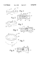
- FIG. 1 is a perspective view of a disk filter according to a first embodiment of the present invention
- FIG. 2 is a cross-sectional view of a driver side inflator using the filter of FIG. 1;
- FIG. 3 is a perspective view of a disk filter according to a second embodiment of the present invention.
- FIG. 4 is a cross-sectional view of a driver side inflator using the filter of FIG. 3;
- FIG. 5 is a perspective view of a tubular filter according to a further embodiment of the present invention.
- FIG. 6 is a cross-sectional view of a driver side inflator using the filter of FIG. 5;
- FIG. 7 is a perspective view of a passenger side inflator in which a filter according to the invention forms a portion of the housing;
- FIG. 8 is an enlarged detail representation of an aggregate/particle configuration according to the present invention.
- FIG. 9 is an enlarged detail representation of a foam/particle configuration according to the present invention.
- the present invention is primarily concerned with the constituents and internal structure for unitary filters for air bags and other pyrotechnic inflation devices. To better describe the invention, therefore, a few of the more common final shapes for filters and inflators are initially noted.
- a disk filter according to the present invention is generally designated by reference numeral 10.
- the filter 10 is appropriately in the form of a disk, with circular upper and lower faces 12 and 14, respectively, and a peripheral sidewall 16.
- Disk filters are typically employed in a driver side air bag inflator having a cylindrical shape, as shown in FIG. 2 and referenced generally as 18.
- the inflator 18 includes top and bottom walls 20 and 22, joined together by a peripheral sidewall 24. Within the confines of these walls, there is a tubular inner wall 26 which defines an initiator cavity 28 containing a first pyrotechnic material. A set of gas ports 30 extend through the inner wall 26 to an annular generant chamber 32 defined between the inner wall and the peripheral sidewall 24. This generant chamber houses a second pyrotechnic material 34, typically referred to as generant, which produces the majority of the gas used to fill the cushion (not shown) of the air bag.
- generant typically referred to as generant
- the filter 10 is mounted in the generant chamber 32, between the top wall 20 and the generant 34.
- the top wall 20 includes a set of exit ports 36 from which the gas generated by the generant may leave the inflator. As may be seen, this gas must pass through the disk filter 10 before exiting from the ports 36. The filter thus may remove particulate materials from the gas and cool the gas.
- FIG. 4 A slight variation of this arrangement is shown in FIG. 4, where like reference numerals denote like elements.
- the only difference is the location of the exit ports 36, which extend through the side wall 24.
- the ports are located, however, such that the gas must pass through the filter before exiting the ports.
- a barrier 38 may be provided between the generant and the filter adjacent the ports. The barrier will force the gas to the radially inward portion of the filter, causing the gas to pass through a sufficient portion of the filter to cause cooling and filtering.
- the filter in this arrangement may be sealed at its upper face 12 to prevent passage of the gas between the filter and the top wall 20 of the inflator. This sealing may be by known sealant compounds, or a layer of ceramic slurry formed of alumina, silica or zirconia.
- a second common filter type, a tubular filter, is shown in FIG. 5, and is designated by reference numeral 40.
- the tubular filter takes the form of a section of a tube, with a sidewall 42 bounded by longitudinal ends 44.
- the tubular filter is commonly used in both driver side and passenger side inflators, with appropriate changes in the proportions and size of the tube.
- a driver side inflator is shown in FIG. 6, and includes many of the same elements as in the inflators of FIGS. 2 and 4. The difference here is that the tubular filter extends about the inner face of the sidewall 24, such that it is between the generant 34 and the side wall containing the exit ports.
- a typical passenger inflator is similar in form to the driver inflator of FIG. 6, but with a few differences. First, passenger side inflators are typically longer. Also, there is typically not a rigid inner wall 26 surrounding the initiator chamber 28, but instead simply a foil wrapping.
- a portion (or all) of the housing may be formed of the unitary filter material, thus combining the function of the filter and the structural housing into a single component.
- the typical sidewall of the inflator has been replaced with a filter sidewall 46 formed from a tubular filter.
- the housing is completed by the top and bottom walls (usually referred to as end caps for passenger side inflators) which may be secured to the filter side wall in a variety of known ways. With appropriate changes this same principle may be used in driver side inflators also.
- the filters according to the present invention may be used within the inflator housing, or form at least a portion of the housing.
- first layer 48 typically at the upstream or entrance face of the filter
- second layer 50 typically at the downstream or exit face of the filter. While these layers may be further subdivided into plural sub-layers, the general form of first and second layers will hold for each embodiment of this invention.
- the two basic forms of filters, disk and tubular the most common arrangements of the two layers are discs and tubes.
- the overall shape is a disc, and the gas flow is along the longitudinal axis.
- the first layer and second layer both take the form of a disc, with the first layer being on the bottom, adjacent the generant, and the second layer on top adjacent the exit ports.
- the overall shape is again a disc, however, while the gas flow begins longitudinally, it exits radially, as required for the inflator of FIG. 4.
- the first layer takes the form of a central disc, while the second layer is tubular and placed at the side wall of the filter.
- the gas flow is fully radial, and the first layer takes the form of a radially interior tube, with the second layer forming a radially exterior tube.
- the first layer will have a generally large porosity, and will function mainly to cool the gas.
- the second layer will have a lower porosity, and will function mainly to remove the particulates. There is of course some filtering in the first layer and some cooling in the second layer.
- the first layer could be formed of a variety of materials. While metals are feasible, it is preferred that ceramics be employed due to their low cost.
- the ceramics may be in the form of bonded ceramic particles 52 (FIG. 8), or a reticulated foam 54 (FIG. 9).
- a loose mass of these particles are formed together into the form of the filter (i.e., disk, etc.).
- This mixture having a consistency similar to wet sand, is molded to a form at least approximating the final desired shape. This may be effected by extrusion of the mixture, isostatic compression, or pressing in a mold or form, to produce a preform or green. The green is then treated (as by simple drying, calcining and/or sintering) to produce the solid, strong unitary filter.
- the particle sizes may vary, depending upon the desired porosity of the first layer. For most uses, particles within the range of about 0.053" (1.35 mm, or 10 mesh) to 0.012" (0.30 mm, or 50 mesh) are acceptable. Various ceramic materials may be employed for the particles, such as silicon carbide, alumina, etc.
- a sacrificial foam typically open-celled polyurethane
- a ceramic slurry for example formed of silica, zirconia or alumina.
- the ceramic material is allowed to dry, and thereafter the ceramic coated sacrificial foam is heated to burn out the polyurethane sacrificial foam, leaving behind the ceramic material in the form of the reticulated foamed ceramic 54.
- Ceramic foams 54 having a porosity in the range of 10-70 pores per inch will typically be acceptable for the first layer.
- the ceramic will provide adequate thermal and filtering properties.
- these ceramics are not strong in tension. As such, the forces of the gas production which place the filter in tension may tend to break the ceramic filter material, reducing its effectiveness. This is especially true for the tube filters, which are subject to hoop stresses upon generation of the gas.
- the second layer 50 of the present invention provides added strength to the filter.
- the second layer 50 is formed of metal, and provides a strong layer serving to reinforce the brittle first layer, in addition to filtering and cooling.
- the second layer is an agglomeration of metal particles 56.
- the particle sizes may vary, depending upon the desired porosity of the first layer. For most uses particles within the range of about 0.053" (1.35 mm, or 10 mesh) to 0.012" (0.30 mm, or 50 mesh) are acceptable.
- Various metals may be used for the particles 56, so long as the melting point of the metal is greater than that expected to be encountered in the inflator. Some suitable metals are stainless steel, carbon steel, aluminum and nickel.
- the first two methods involve forming a mass of the particles into the desired shape and then sintering the particles. The difference between these first two methods is whether the particles are formed in to their shape on or off of the first ceramic layer.
- the third method of making the metal second layer is plasma arc deposition.
- the second layer is formed as a planar disk, as in FIG. 1, the green must be formed directly upon the first layer, either by pressing the mass of particles prior to sintering, or by plasma arc deposition. If the second layer is in the form of a tube, however, any of the three processes may be used. The reasons for this will be explained more fully below.
- the first method of making the metal second layer is pressing of the metal second layer particles directly upon the first layer.
- the first layer may be a ceramic foam or a ceramic aggregate.
- the first layer is placed within an appropriate mold. Thereafter a mass of the metal particles are also placed in the mold, and compressed. This compression forces the metal particles into their form as a green. The particles will then retain their shape, either by use of a binder, or simply due to the compression if it is sufficiently great. Additionally, this compression can secure the green to the first layer.
- FIG. 8 there is shown an expanded representation of the sintered ceramic aggregate 52 of first layer 48 and the metal particles 56 of the second layer 50.
- the particles 56 can be forced into the interstices of the first layer. This contact between the ceramic and metal, especially if a binder is used, serves to hold the second layer to the first. Additionally, forcing the metal into the tortuous interstices can cause numerous interference connections, which further serve to secure the second layer to the first. This is especially true after sintering.
- FIG. 9 shows an expanded representation of the reticulated carbon foam first layer 48, and the metal particles of the second layer 50.
- the particles 56 can be forced into the pores. This results in contact and interference connections as with the example above.
- the combination of the first and second layers are sintered. This is performed at a suitable temperature for the metal, rather than the previously formed ceramic first layer. This sintering step serves to firmly secure the particles to each other to complete the second layer, as well as further securing the metal second layer to the ceramic first layer.
- the second method of forming the metal second layer will now be described. This process is believed to be the same regardless of whether the first layer is the ceramic foam, or the ceramic aggregate. It is this process which is not believed to be suitable for planar layers, but only for tubular, as described below.
- the first layer 48 is formed and sintered, as before. Thereafter, a mass of metal particles are pressed together in a mold to form the tubular second layer green. This pressing is done without the first layer, so that the green contains only the metal of the second layer. During this forming, the inner diameter of the second layer 50 is sized to just fit over the outer diameter of the disk or tubular first layer 48, similar to a close sliding fit. The second layer green is then sintered.
- the tubular second layer 50 is slid over the outer diameter of the first layer 48. Since the metal of the second layer has a greater coefficient of thermal expansion than the ceramic first layer, the second layer shrinks more than the first layer during cooling. As such, this creates an interference fit which secures the second layer to the first. Additionally, this greater contraction of the second layer 50 will place the first layer 48 in compression. This serves to pre-load the ceramic first layer, increasing the tensile load it may bear.
- a somewhat similar effect may be achieved upon sintering the green second layer on the ceramic first layer according to the first process. Specifically, upon cooling the tubular second layer will contract upon the inner first layer to place it in compression. This effect may be enhanced by maintaining pressure upon the second layer 50 during the sintering process.
- this contraction effect is used to securely retain the tubular second layer upon the disk or tubular second layer. It should also be apparent that this contraction can not be used to reliably secure the planar second layer of FIG. 1. Specifically, while there could be some increased interference and compression of the first layer via the interference created during initial pressing, this would be minimal, and would not serve to adequately maintain the two layers together.
- the third method of providing the second layer of metal particles is plasma arc spraying, also known as flame spray deposition.
- plasma arc spraying also known as flame spray deposition.
- a powder typically metallic, is introduced into the arc of a torch. The particles are propelled toward the deposition surface by the torch, and at the same time heated. This heating is sufficient to cause the metal particles to bond to the deposition surface (and each other), but does not cause a true melting of the particles. As such, the deposition surface receives a coating of fine particles.
- the first, ceramic, layer is initially formed and sintered. Thereafter, standard plasma arc spraying equipment is employed to provide a thin coating of metal particles upon the first layer, thus forming the second metal layer.
- the filter may be rotated, reciprocated, or otherwise moved during the deposition process to provide a uniform coating.
- the powder is a metal which has a melting point sufficiently high that the final metal layer will survive the temperatures generated during operation of the inflator.
- Typical metals which may be employed are stainless steel, carbon steel, aluminum and nickels.
- the size of particles used may be the same as with the sintered powder, namely within the range of about 50-200 microns.
- the particles are applied by this process in a random manner, which is essentially the same as that depicted in FIGS. 7 and 8, although possibly with less intermingling.
- Several passes of the arc over the first layer may be required to achieve a sufficient thickness.
- the final thickness will depend upon a variety of factors, including: porosity of the first, ceramic, layer; strength of the first, ceramic, layer; metal particle size; and desired final porosity.
- the particles will be applied in a thickness sufficient to provide the strength necessary to support the first layer, and to provide a desired final porosity for the completed filter.
- the final (i.e., inner and outer layers combined) filter have a porosity of about 2-15 CFM/sq. ft. of filter surface area at a pressure of 1/2" of water. This may of course be achieved by various combinations of first layer porosities and second layer porosities. So long as adequate cooling, adequate filtration, and a porosity in this 2-15 CFM range is provided, the particular porosity of any individual layer (or sub-layer) is not critical.
- first layer 48 of the ceramic aggregate 52 While the above arrangements are acceptable, it possible to make modifications to the first layer 48 of the ceramic aggregate 52 and still practice the present invention. The possible modifications may make the first layer 48 stronger and/or provide better gas diffusion. Even if made stronger, however, the second layer 50 is still applied.
- the aggregate sizes may be characterized as large grits and small grits, respectively, with the large aggregate being from about 0.053-0.028" (1.35-0.70 mm, or 10-25 mesh), and the small aggregate being about one-third to one half the size of the large grit, or about 0.030-0.012" (0.750-0.30 mm, or 20-50 mesh). It is noted that, even though the noted ranges overlap, it is not envisioned that the large and small aggregates used would be of approximately the same size.
- the difference in particle size be appreciable, and at least on the order of 1:1.5, and preferably about a 2:1 ratio.
- These two different aggregate sizes may be mixed in proportions between about 1:1-1:10 small to large particles by weight.
- the small aggregate serves to fill the void areas between the large grit, in a manner similar to the small metal particles filling the interstices between the large aggregate in FIG. 8, reducing the size of any large passages through the first layer, thus increasing filtration of solids.
- the aggregate sizes may be characterized as large aggregate and very small aggregate, respectively.
- the large aggregate may again have a size within the range of about 0.053-0.028" (1.35-0.70 mm, or 10-25 mesh), though the very small aggregate has a size in the range of about 0.0029-0.0014" (0.075-0.035 mm, or 200-400 mesh).
- the two aggregate sizes may be mixed in a proportion between about 1:2-1:5 very small to large particles by weight.
- the smaller sized aggregate at least partially fills, and reduces the size of, the interstitial spaces between the large aggregate, thus reducing the size of a solid object which may pass through the filter.
- this can also reduce the amount of interference between the first and second layers, as the smaller aggregate may block the metal particles from entering the interstices.
- this problem can be reduced. Additionally, such a problem does not exist if the first and second layers are secured together using the thermal contraction method noted above.
- a second arrangement for the first layer 48 is to provide the disparate aggregate sizes, yet in a more layered manner, similar to the layering between the first and second layers in FIG. 7. With this arrangement, the aggregate sizes are not uniformly mixed, but are kept separate. Each of the aggregate sizes is subjected to the forming process described above to form a green, but of a reduced thickness such that each green will form a sub-layer of the completed filter. These layers will of course extend in the direction of gas flow through the filter.
- the green layers may be assembled together within a mold and pressed or compressed together to unite the greens. This may be facilitated by reducing the amount of pressure applied to initially form the individual green sub-layers, compared to a single forming step as described above, such that they may be further compacted during this second step. It is preferred that all sub-layers of the filter be assembled at the same time in this second compacting step, but an individual layer or layers may be pressed into position separately. This second pressing or compacting step forces the disparate layers together sufficiently that they will be secured together.
- the pressing or compacting to form the unitary layer 48 will cause some amount of intermingling of aggregate sizes across the boundary between adjacent layers.
- This intermingling will produce a transition zone of mixed size grit, similar to the uniformly mixed aggregate sizes discussed above.
- This transition zone will thus have greatly reduced voids and passageways.
- the gas flow from the large aggregate sub-layer will be diffused before entering the smaller aggregate sub-layer(s) downstream. This will improve filtering, as a more even flow will be filtered by the smaller aggregate sub-layer(s).
- the final form must fit within the inflator, and as such the thickness of the sub-layers depends upon such final size.
- the number of sub-layers, and their order, however, may be varied for best results in a particular application.
- the benefits of using multiple aggregate sizes are not limited to the ceramic first layer.
- the metal particles for the sintered second layer may also be used in essentially identical manners as described above. The only differences would be the possible deletion of the binder, as metal particles may be forced into a green simply by application of sufficient pressure, if desired, and the temperatures required to sinter the green would be reduced to known metal sintering temperatures. All other factors, including particle sizes, and mixture percentages, are essentially identical.
- the final forms described above may also be achieved in the plasma arc metal layer.
- two different particle sizes may be fed to the torch to provide the fully intermingled layer.
- several passes may be deposited with a first particle size, and then further passes deposited with a different particle size.
- the plasma arc deposited particles will achieve a configuration similar to that for the sintered metal particles.
Abstract
Description
Claims (19)
Priority Applications (3)
| Application Number | Priority Date | Filing Date | Title |
|---|---|---|---|
| US08/586,044 US5746793A (en) | 1996-01-16 | 1996-01-16 | Reinforced ceramic air bag filters |
| EP97300092A EP0785014A1 (en) | 1996-01-16 | 1997-01-09 | Reinforced ceramic air bag filters |
| JP1997000120U JP3039607U (en) | 1996-01-16 | 1997-01-16 | Unit filter for pyrotechnic inflator |
Applications Claiming Priority (1)
| Application Number | Priority Date | Filing Date | Title |
|---|---|---|---|
| US08/586,044 US5746793A (en) | 1996-01-16 | 1996-01-16 | Reinforced ceramic air bag filters |
Publications (1)
| Publication Number | Publication Date |
|---|---|
| US5746793A true US5746793A (en) | 1998-05-05 |
Family
ID=24344072
Family Applications (1)
| Application Number | Title | Priority Date | Filing Date |
|---|---|---|---|
| US08/586,044 Expired - Fee Related US5746793A (en) | 1996-01-16 | 1996-01-16 | Reinforced ceramic air bag filters |
Country Status (3)
| Country | Link |
|---|---|
| US (1) | US5746793A (en) |
| EP (1) | EP0785014A1 (en) |
| JP (1) | JP3039607U (en) |
Cited By (7)
| Publication number | Priority date | Publication date | Assignee | Title |
|---|---|---|---|---|
| US20040113405A1 (en) * | 2002-12-12 | 2004-06-17 | Trw Automotive Safety Systems Gmbh | Gas bag module |
| US6929866B1 (en) * | 1998-11-16 | 2005-08-16 | Ultramet | Composite foam structures |
| WO2006004934A2 (en) * | 2004-06-29 | 2006-01-12 | Automotive Systems Laboratory, Inc. | Gas generating system |
| US20060082113A1 (en) * | 2004-10-19 | 2006-04-20 | Smith Bradley W | Inflator device for airbag installations |
| WO2014209698A1 (en) * | 2013-06-26 | 2014-12-31 | Flsmidth A/S | Filter media and methods of manufacturing thereof |
| WO2016112273A1 (en) * | 2015-01-08 | 2016-07-14 | Trafalgar Associates, LLC | Filtration devices for use in automotive airbag applications and related methods |
| CN106488365A (en) * | 2015-08-27 | 2017-03-08 | 苹果公司 | There is the audio tweeter that rigidity adsorbs insertion body |
Families Citing this family (5)
| Publication number | Priority date | Publication date | Assignee | Title |
|---|---|---|---|---|
| JP2572819Y2 (en) * | 1992-02-13 | 1998-05-25 | ポップリベット・ファスナー株式会社 | Screw grommet |
| KR20010072950A (en) * | 1998-08-24 | 2001-07-31 | 와이너 길버트 피. | Porous structures and methods and apparatus for forming porous structures |
| WO2000027673A1 (en) * | 1998-11-09 | 2000-05-18 | Nippon Kayaku Kabushiki-Kaisha | Gas generator |
| DE102007032060B4 (en) * | 2007-07-10 | 2019-05-23 | Herding Gmbh Filtertechnik | Heat-resistant filter element with coating and method for its production |
| CN109908664B (en) * | 2019-04-08 | 2021-10-22 | 永康市宝莱斯杯业有限公司 | Filter element formula capable of rapidly precipitating mineral substances and production process thereof |
Citations (41)
| Publication number | Priority date | Publication date | Assignee | Title |
|---|---|---|---|---|
| US2995088A (en) * | 1959-06-29 | 1961-08-08 | Bermite Powder Company | Multi-stage igniter charge |
| US3853332A (en) * | 1972-03-31 | 1974-12-10 | Specialty Prod Dev Corp | Porous diffuser for gas supply to passenger restraint |
| JPS5048797A (en) * | 1973-08-31 | 1975-05-01 | ||
| US3912458A (en) * | 1972-12-26 | 1975-10-14 | Nissan Motor | Air bag gas generator casing |
| US3950263A (en) * | 1972-12-26 | 1976-04-13 | Nissan Motor Co., Ltd. | Gas cooling and filtering agent for air bag gas generator |
| US4265659A (en) * | 1979-10-09 | 1981-05-05 | Swiss Aluminium Ltd. | Molten metal filter |
| US4316874A (en) * | 1978-05-29 | 1982-02-23 | Nissan Motor Co., Ltd. | Gas generator utilizing granular silicon carbide as coolant |
| US4568595A (en) * | 1984-04-26 | 1986-02-04 | Morris Jeffrey R | Coated ceramic structure and method of making same |
| JPS61149221A (en) * | 1984-12-22 | 1986-07-07 | Toyota Motor Corp | Filter for collecting particulate of diesel engine |
| US4629483A (en) * | 1986-01-06 | 1986-12-16 | Refractron Corp. | Ceramic filter with plural layers of different porosity |
| US4732594A (en) * | 1985-08-16 | 1988-03-22 | Swiss Aluminium Ltd. | Process for scrubbing exhaust gases from diesel engines and filter cartridge for carrying out the process |
| US4810273A (en) * | 1985-04-17 | 1989-03-07 | Ngk Insulators, Ltd. | Porous ceramic filter |
| US4846906A (en) * | 1987-12-02 | 1989-07-11 | The Duriron Company, Inc. | Methods for the manufacture of porous ceramic shapes containing membraneous surfaces |
| US4865635A (en) * | 1988-08-17 | 1989-09-12 | Talley Automotive Products, Inc. | Filter assembly for non-welded inflator device |
| JPH02169007A (en) * | 1988-12-21 | 1990-06-29 | Toyota Motor Corp | Particulate collecting filter |
| US4965101A (en) * | 1987-12-10 | 1990-10-23 | Swiss Aluminium Ltd. | Ceramic foam for filters for cleaning exhaust gases of diesel engines |
| US4976760A (en) * | 1987-12-02 | 1990-12-11 | Cercona, Inc. | Porous ceramic article for use as a filter for removing particulates from diesel exhaust gases |
| SU1632484A1 (en) * | 1989-04-11 | 1991-03-07 | Предприятие П/Я В-8729 | Low-temperature gas generator |
| US5000479A (en) * | 1988-09-21 | 1991-03-19 | Bayern-Chemie Gesellschaft Fuer Flugchemische Antriebe Mbh | Housing for a gas generator |
| US5064459A (en) * | 1989-08-11 | 1991-11-12 | Bayern-Chemie Gesellschaft Fur Flugchemische Antriebe Mbh | Filter arrangement for airbag gas generators |
| US5071457A (en) * | 1985-11-25 | 1991-12-10 | Industrial Filter & Pump Mfg. Co. | Composite for filtering hot gas and method of its manufacture |
| US5075160A (en) * | 1988-06-13 | 1991-12-24 | Martin Marietta Energy Systems, Inc. | Ceramic fiber reinforced filter |
| JPH042542A (en) * | 1990-04-19 | 1992-01-07 | Sumitomo Electric Ind Ltd | Filter for air bag gas generator |
| US5196120A (en) * | 1991-05-13 | 1993-03-23 | Minnesota Mining And Manufacturing Company | Ceramic-ceramic composite filter |
| US5204068A (en) * | 1991-05-01 | 1993-04-20 | Trw Inc. | Filter |
| US5215721A (en) * | 1990-09-06 | 1993-06-01 | Nippon Oil And Fats Co., Ltd. | Gas generating device |
| US5230726A (en) * | 1992-04-30 | 1993-07-27 | Morton International, Inc. | Spiral wrapped gas generator filter |
| US5346254A (en) * | 1993-02-01 | 1994-09-13 | Trw Inc. | Inflator assembly |
| US5351619A (en) * | 1991-02-18 | 1994-10-04 | Imperial Chemical Industries Plc | Gas generator ignited by lamina or film |
| US5364586A (en) * | 1993-08-17 | 1994-11-15 | Ultram International L.L.C. | Process for the production of porous membranes |
| US5368329A (en) * | 1993-03-03 | 1994-11-29 | Morton International, Inc. | Dual stage inflator |
| EP0626295A1 (en) * | 1993-05-24 | 1994-11-30 | Morton International, Inc. | Inflatable restraint system inflator emission treatment |
| WO1994027842A1 (en) * | 1993-05-20 | 1994-12-08 | Ultramet | Filter and method of forming |
| US5374407A (en) * | 1992-04-08 | 1994-12-20 | Daicel Chemical Industries, Ltd. | Gas generator with porous outer wall |
| EP0640515A1 (en) * | 1993-08-30 | 1995-03-01 | Morton International, Inc. | Pyrotechnic air bag inflator with unitary filter |
| US5466420A (en) * | 1994-07-26 | 1995-11-14 | Morton International, Inc. | Air bag inflator |
| US5503806A (en) * | 1994-07-26 | 1996-04-02 | Morton International, Inc. | Varying permeability filter for airbag inflator |
| WO1996010453A2 (en) * | 1994-10-01 | 1996-04-11 | Imas Technology Limited | A filter, apparatus including the filter and a method of use of the apparatus |
| US5547638A (en) * | 1993-08-30 | 1996-08-20 | Morton International, Inc. | Pyrotechnic air bag inflator with unitary filter |
| US5564741A (en) * | 1995-06-12 | 1996-10-15 | Morton International, Inc. | Air bag filter and seal arrangement |
| US5582427A (en) * | 1995-06-28 | 1996-12-10 | Morton International, Inc. | Dual-wall pyrotechnic air bag inflator with tortuous gas flow |
-
1996
- 1996-01-16 US US08/586,044 patent/US5746793A/en not_active Expired - Fee Related
-
1997
- 1997-01-09 EP EP97300092A patent/EP0785014A1/en not_active Withdrawn
- 1997-01-16 JP JP1997000120U patent/JP3039607U/en not_active Expired - Lifetime
Patent Citations (45)
| Publication number | Priority date | Publication date | Assignee | Title |
|---|---|---|---|---|
| US2995088A (en) * | 1959-06-29 | 1961-08-08 | Bermite Powder Company | Multi-stage igniter charge |
| US3853332A (en) * | 1972-03-31 | 1974-12-10 | Specialty Prod Dev Corp | Porous diffuser for gas supply to passenger restraint |
| US3912458A (en) * | 1972-12-26 | 1975-10-14 | Nissan Motor | Air bag gas generator casing |
| US3950263A (en) * | 1972-12-26 | 1976-04-13 | Nissan Motor Co., Ltd. | Gas cooling and filtering agent for air bag gas generator |
| JPS5048797A (en) * | 1973-08-31 | 1975-05-01 | ||
| US4316874A (en) * | 1978-05-29 | 1982-02-23 | Nissan Motor Co., Ltd. | Gas generator utilizing granular silicon carbide as coolant |
| US4265659A (en) * | 1979-10-09 | 1981-05-05 | Swiss Aluminium Ltd. | Molten metal filter |
| US4568595A (en) * | 1984-04-26 | 1986-02-04 | Morris Jeffrey R | Coated ceramic structure and method of making same |
| JPS61149221A (en) * | 1984-12-22 | 1986-07-07 | Toyota Motor Corp | Filter for collecting particulate of diesel engine |
| US4810273A (en) * | 1985-04-17 | 1989-03-07 | Ngk Insulators, Ltd. | Porous ceramic filter |
| US4732594A (en) * | 1985-08-16 | 1988-03-22 | Swiss Aluminium Ltd. | Process for scrubbing exhaust gases from diesel engines and filter cartridge for carrying out the process |
| US5071457A (en) * | 1985-11-25 | 1991-12-10 | Industrial Filter & Pump Mfg. Co. | Composite for filtering hot gas and method of its manufacture |
| US4629483A (en) * | 1986-01-06 | 1986-12-16 | Refractron Corp. | Ceramic filter with plural layers of different porosity |
| US4846906A (en) * | 1987-12-02 | 1989-07-11 | The Duriron Company, Inc. | Methods for the manufacture of porous ceramic shapes containing membraneous surfaces |
| US4976760A (en) * | 1987-12-02 | 1990-12-11 | Cercona, Inc. | Porous ceramic article for use as a filter for removing particulates from diesel exhaust gases |
| US4965101A (en) * | 1987-12-10 | 1990-10-23 | Swiss Aluminium Ltd. | Ceramic foam for filters for cleaning exhaust gases of diesel engines |
| US5075160A (en) * | 1988-06-13 | 1991-12-24 | Martin Marietta Energy Systems, Inc. | Ceramic fiber reinforced filter |
| US4865635A (en) * | 1988-08-17 | 1989-09-12 | Talley Automotive Products, Inc. | Filter assembly for non-welded inflator device |
| US5000479A (en) * | 1988-09-21 | 1991-03-19 | Bayern-Chemie Gesellschaft Fuer Flugchemische Antriebe Mbh | Housing for a gas generator |
| JPH02169007A (en) * | 1988-12-21 | 1990-06-29 | Toyota Motor Corp | Particulate collecting filter |
| SU1632484A1 (en) * | 1989-04-11 | 1991-03-07 | Предприятие П/Я В-8729 | Low-temperature gas generator |
| US5064459A (en) * | 1989-08-11 | 1991-11-12 | Bayern-Chemie Gesellschaft Fur Flugchemische Antriebe Mbh | Filter arrangement for airbag gas generators |
| JPH042542A (en) * | 1990-04-19 | 1992-01-07 | Sumitomo Electric Ind Ltd | Filter for air bag gas generator |
| US5215721A (en) * | 1990-09-06 | 1993-06-01 | Nippon Oil And Fats Co., Ltd. | Gas generating device |
| US5351619A (en) * | 1991-02-18 | 1994-10-04 | Imperial Chemical Industries Plc | Gas generator ignited by lamina or film |
| US5204068A (en) * | 1991-05-01 | 1993-04-20 | Trw Inc. | Filter |
| US5196120A (en) * | 1991-05-13 | 1993-03-23 | Minnesota Mining And Manufacturing Company | Ceramic-ceramic composite filter |
| US5374407A (en) * | 1992-04-08 | 1994-12-20 | Daicel Chemical Industries, Ltd. | Gas generator with porous outer wall |
| US5230726A (en) * | 1992-04-30 | 1993-07-27 | Morton International, Inc. | Spiral wrapped gas generator filter |
| US5346254A (en) * | 1993-02-01 | 1994-09-13 | Trw Inc. | Inflator assembly |
| US5368329A (en) * | 1993-03-03 | 1994-11-29 | Morton International, Inc. | Dual stage inflator |
| US5372380A (en) * | 1993-05-20 | 1994-12-13 | Ultramet | Filter and method of forming |
| WO1994027842A1 (en) * | 1993-05-20 | 1994-12-08 | Ultramet | Filter and method of forming |
| EP0626295A1 (en) * | 1993-05-24 | 1994-11-30 | Morton International, Inc. | Inflatable restraint system inflator emission treatment |
| US5378015A (en) * | 1993-05-24 | 1995-01-03 | Morton International, Inc. | Inflatable restraint system inflator emission treatment |
| US5364586A (en) * | 1993-08-17 | 1994-11-15 | Ultram International L.L.C. | Process for the production of porous membranes |
| US5556439A (en) * | 1993-08-30 | 1996-09-17 | Morton International, Inc. | Unitary filter for pyrotechnic air bag inflator |
| US5547638A (en) * | 1993-08-30 | 1996-08-20 | Morton International, Inc. | Pyrotechnic air bag inflator with unitary filter |
| EP0640515A1 (en) * | 1993-08-30 | 1995-03-01 | Morton International, Inc. | Pyrotechnic air bag inflator with unitary filter |
| US5466420A (en) * | 1994-07-26 | 1995-11-14 | Morton International, Inc. | Air bag inflator |
| US5503806A (en) * | 1994-07-26 | 1996-04-02 | Morton International, Inc. | Varying permeability filter for airbag inflator |
| US5466420B1 (en) * | 1994-07-26 | 1998-10-06 | Morton Int Inc | Air bag inflator |
| WO1996010453A2 (en) * | 1994-10-01 | 1996-04-11 | Imas Technology Limited | A filter, apparatus including the filter and a method of use of the apparatus |
| US5564741A (en) * | 1995-06-12 | 1996-10-15 | Morton International, Inc. | Air bag filter and seal arrangement |
| US5582427A (en) * | 1995-06-28 | 1996-12-10 | Morton International, Inc. | Dual-wall pyrotechnic air bag inflator with tortuous gas flow |
Cited By (15)
| Publication number | Priority date | Publication date | Assignee | Title |
|---|---|---|---|---|
| US6929866B1 (en) * | 1998-11-16 | 2005-08-16 | Ultramet | Composite foam structures |
| US20040113405A1 (en) * | 2002-12-12 | 2004-06-17 | Trw Automotive Safety Systems Gmbh | Gas bag module |
| WO2006004934A2 (en) * | 2004-06-29 | 2006-01-12 | Automotive Systems Laboratory, Inc. | Gas generating system |
| US20060016362A1 (en) * | 2004-06-29 | 2006-01-26 | Quioc Eduardo L | Gas generating system |
| US8608196B2 (en) | 2004-06-29 | 2013-12-17 | Tk Holdings Inc. | Gas generating system |
| WO2006004934A3 (en) * | 2004-06-29 | 2007-05-03 | Automotive Systems Lab | Gas generating system |
| US7347448B2 (en) | 2004-10-19 | 2008-03-25 | Autoliv Asp, Inc. | Inflator device for airbag installations |
| US20060082113A1 (en) * | 2004-10-19 | 2006-04-20 | Smith Bradley W | Inflator device for airbag installations |
| WO2014209698A1 (en) * | 2013-06-26 | 2014-12-31 | Flsmidth A/S | Filter media and methods of manufacturing thereof |
| CN105358230A (en) * | 2013-06-26 | 2016-02-24 | Fl史密斯公司 | Filter media and methods of manufacturing thereof |
| WO2016112273A1 (en) * | 2015-01-08 | 2016-07-14 | Trafalgar Associates, LLC | Filtration devices for use in automotive airbag applications and related methods |
| US20160200282A1 (en) * | 2015-01-08 | 2016-07-14 | Trafalgar Associates, LLC | Filtration devices for use in automotive airbag applications and related methods |
| US10336286B2 (en) * | 2015-01-08 | 2019-07-02 | Trafalgar Associates, LLC | Filtration devices for use in automotive airbag applications and related methods |
| CN106488365A (en) * | 2015-08-27 | 2017-03-08 | 苹果公司 | There is the audio tweeter that rigidity adsorbs insertion body |
| CN106488365B (en) * | 2015-08-27 | 2019-08-20 | 苹果公司 | The method of audio tweeter and formation loudspeaker with rigidity absorption insertion body |
Also Published As
| Publication number | Publication date |
|---|---|
| JP3039607U (en) | 1997-07-31 |
| EP0785014A1 (en) | 1997-07-23 |
Similar Documents
| Publication | Publication Date | Title |
|---|---|---|
| US5746793A (en) | Reinforced ceramic air bag filters | |
| US8128722B2 (en) | Honeycomb filter for purifying exhaust gases, adhesive, coating material, and manufacturing method of honeycomb filter for purifying exhaust gases | |
| EP0228631B1 (en) | Ceramic filter with plural layers of different porosity | |
| US4662911A (en) | Equipment for trapping particulates in engine exhaust gas | |
| US7585471B2 (en) | Honeycomb structured body and exhaust gas purifying device | |
| US5666726A (en) | Method of making a mounting mat for fragile structures such as catalytic converters | |
| EP1978006B1 (en) | Honeycomb filter | |
| EP1382444B1 (en) | A filter for purifying exhaust gas | |
| US7214253B2 (en) | Filtering body comprising a plurality of filtering units, in particular designed for a particulate filter | |
| EP1245262B1 (en) | Method of manufacturing an exhaust gas purifying filter | |
| CN101094976B (en) | Honeycomb body with an at least partially ceramic honeycomb structure and a receptacle for a measurement sensor, and process for producing such a honeycomb body | |
| US5759219A (en) | Unitary drop-in airbag filters | |
| US5372380A (en) | Filter and method of forming | |
| WO2006041174A1 (en) | Ceramic honeycomb structure | |
| EP2957548B1 (en) | Honeycomb structure | |
| JP2004113887A (en) | Honeycomb catalyst carrier and its production method | |
| EP2138290B1 (en) | Method for manufacturing a honeycomb structure | |
| US6596168B2 (en) | Filter element and method for the manufacture | |
| EP2067515B1 (en) | Processes for producing ceramic honeycomb filter | |
| CA2036385A1 (en) | Permeable, porous body for the treatment of gases and/or vapors and/or liquids and method of producing it | |
| AU2002226432A1 (en) | Filter element and method for the manufacture | |
| US3762026A (en) | Method of making a high temperature body of uniform porosity | |
| US3961909A (en) | Uniformly porous body | |
| US20060231988A1 (en) | Multilayer ceramic composite | |
| CA1227811A (en) | Ceramic foam cement |
Legal Events
| Date | Code | Title | Description |
|---|---|---|---|
| AS | Assignment |
Owner name: MORTON INTERNATIONAL, INC., ILLINOIS Free format text: ASSIGNMENT OF ASSIGNORS INTEREST;ASSIGNORS:LETENDRE, GUY R.;TEVEROVSKY, ALEXANDER;MARJANKSI, GEORGE C.;AND OTHERS;REEL/FRAME:007841/0770;SIGNING DATES FROM 19951220 TO 19960110 |
|
| AS | Assignment |
Owner name: AUTOLIV ASP, INC, UTAH Free format text: MERGER AND CHANGE OF NAME;ASSIGNOR:MORTON INTERNATIONAL, INC;REEL/FRAME:009866/0350 Effective date: 19970429 |
|
| FEPP | Fee payment procedure |
Free format text: PAYOR NUMBER ASSIGNED (ORIGINAL EVENT CODE: ASPN); ENTITY STATUS OF PATENT OWNER: LARGE ENTITY |
|
| FEPP | Fee payment procedure |
Free format text: PAYOR NUMBER ASSIGNED (ORIGINAL EVENT CODE: ASPN); ENTITY STATUS OF PATENT OWNER: LARGE ENTITY Free format text: PAYER NUMBER DE-ASSIGNED (ORIGINAL EVENT CODE: RMPN); ENTITY STATUS OF PATENT OWNER: LARGE ENTITY |
|
| FEPP | Fee payment procedure |
Free format text: PAYOR NUMBER ASSIGNED (ORIGINAL EVENT CODE: ASPN); ENTITY STATUS OF PATENT OWNER: LARGE ENTITY Free format text: PAYER NUMBER DE-ASSIGNED (ORIGINAL EVENT CODE: RMPN); ENTITY STATUS OF PATENT OWNER: LARGE ENTITY |
|
| FPAY | Fee payment |
Year of fee payment: 4 |
|
| REMI | Maintenance fee reminder mailed | ||
| LAPS | Lapse for failure to pay maintenance fees | ||
| LAPS | Lapse for failure to pay maintenance fees |
Free format text: PATENT EXPIRED FOR FAILURE TO PAY MAINTENANCE FEES (ORIGINAL EVENT CODE: EXP.); ENTITY STATUS OF PATENT OWNER: LARGE ENTITY |
|
| STCH | Information on status: patent discontinuation |
Free format text: PATENT EXPIRED DUE TO NONPAYMENT OF MAINTENANCE FEES UNDER 37 CFR 1.362 |
|
| FP | Lapsed due to failure to pay maintenance fee |
Effective date: 20060505 |