US5767022A - Friction pad containing high temperature stable continuous filament glass fibers - Google Patents
Friction pad containing high temperature stable continuous filament glass fibers Download PDFInfo
- Publication number
- US5767022A US5767022A US08/768,868 US76886896A US5767022A US 5767022 A US5767022 A US 5767022A US 76886896 A US76886896 A US 76886896A US 5767022 A US5767022 A US 5767022A
- Authority
- US
- United States
- Prior art keywords
- friction pad
- fibers
- high temperature
- mole percent
- glass fibers
- Prior art date
- Legal status (The legal status is an assumption and is not a legal conclusion. Google has not performed a legal analysis and makes no representation as to the accuracy of the status listed.)
- Expired - Fee Related
Links
Images


Classifications
-
- C—CHEMISTRY; METALLURGY
- C03—GLASS; MINERAL OR SLAG WOOL
- C03C—CHEMICAL COMPOSITION OF GLASSES, GLAZES OR VITREOUS ENAMELS; SURFACE TREATMENT OF GLASS; SURFACE TREATMENT OF FIBRES OR FILAMENTS MADE FROM GLASS, MINERALS OR SLAGS; JOINING GLASS TO GLASS OR OTHER MATERIALS
- C03C13/00—Fibre or filament compositions
-
- Y—GENERAL TAGGING OF NEW TECHNOLOGICAL DEVELOPMENTS; GENERAL TAGGING OF CROSS-SECTIONAL TECHNOLOGIES SPANNING OVER SEVERAL SECTIONS OF THE IPC; TECHNICAL SUBJECTS COVERED BY FORMER USPC CROSS-REFERENCE ART COLLECTIONS [XRACs] AND DIGESTS
- Y10—TECHNICAL SUBJECTS COVERED BY FORMER USPC
- Y10T—TECHNICAL SUBJECTS COVERED BY FORMER US CLASSIFICATION
- Y10T428/00—Stock material or miscellaneous articles
- Y10T428/26—Web or sheet containing structurally defined element or component, the element or component having a specified physical dimension
- Y10T428/268—Monolayer with structurally defined element
-
- Y—GENERAL TAGGING OF NEW TECHNOLOGICAL DEVELOPMENTS; GENERAL TAGGING OF CROSS-SECTIONAL TECHNOLOGIES SPANNING OVER SEVERAL SECTIONS OF THE IPC; TECHNICAL SUBJECTS COVERED BY FORMER USPC CROSS-REFERENCE ART COLLECTIONS [XRACs] AND DIGESTS
- Y10—TECHNICAL SUBJECTS COVERED BY FORMER USPC
- Y10T—TECHNICAL SUBJECTS COVERED BY FORMER US CLASSIFICATION
- Y10T428/00—Stock material or miscellaneous articles
- Y10T428/26—Web or sheet containing structurally defined element or component, the element or component having a specified physical dimension
- Y10T428/269—Web or sheet containing structurally defined element or component, the element or component having a specified physical dimension including synthetic resin or polymer layer or component
-
- Y—GENERAL TAGGING OF NEW TECHNOLOGICAL DEVELOPMENTS; GENERAL TAGGING OF CROSS-SECTIONAL TECHNOLOGIES SPANNING OVER SEVERAL SECTIONS OF THE IPC; TECHNICAL SUBJECTS COVERED BY FORMER USPC CROSS-REFERENCE ART COLLECTIONS [XRACs] AND DIGESTS
- Y10—TECHNICAL SUBJECTS COVERED BY FORMER USPC
- Y10T—TECHNICAL SUBJECTS COVERED BY FORMER US CLASSIFICATION
- Y10T428/00—Stock material or miscellaneous articles
- Y10T428/30—Self-sustaining carbon mass or layer with impregnant or other layer
-
- Y—GENERAL TAGGING OF NEW TECHNOLOGICAL DEVELOPMENTS; GENERAL TAGGING OF CROSS-SECTIONAL TECHNOLOGIES SPANNING OVER SEVERAL SECTIONS OF THE IPC; TECHNICAL SUBJECTS COVERED BY FORMER USPC CROSS-REFERENCE ART COLLECTIONS [XRACs] AND DIGESTS
- Y10—TECHNICAL SUBJECTS COVERED BY FORMER USPC
- Y10T—TECHNICAL SUBJECTS COVERED BY FORMER US CLASSIFICATION
- Y10T428/00—Stock material or miscellaneous articles
- Y10T428/31504—Composite [nonstructural laminate]
- Y10T428/31551—Of polyamidoester [polyurethane, polyisocyanate, polycarbamate, etc.]
- Y10T428/31627—Next to aldehyde or ketone condensation product
-
- Y—GENERAL TAGGING OF NEW TECHNOLOGICAL DEVELOPMENTS; GENERAL TAGGING OF CROSS-SECTIONAL TECHNOLOGIES SPANNING OVER SEVERAL SECTIONS OF THE IPC; TECHNICAL SUBJECTS COVERED BY FORMER USPC CROSS-REFERENCE ART COLLECTIONS [XRACs] AND DIGESTS
- Y10—TECHNICAL SUBJECTS COVERED BY FORMER USPC
- Y10T—TECHNICAL SUBJECTS COVERED BY FORMER US CLASSIFICATION
- Y10T442/00—Fabric [woven, knitted, or nonwoven textile or cloth, etc.]
- Y10T442/20—Coated or impregnated woven, knit, or nonwoven fabric which is not [a] associated with another preformed layer or fiber layer or, [b] with respect to woven and knit, characterized, respectively, by a particular or differential weave or knit, wherein the coating or impregnation is neither a foamed material nor a free metal or alloy layer
- Y10T442/2344—Coating or impregnation is anti-slip or friction-increasing other than specified as an abrasive
-
- Y—GENERAL TAGGING OF NEW TECHNOLOGICAL DEVELOPMENTS; GENERAL TAGGING OF CROSS-SECTIONAL TECHNOLOGIES SPANNING OVER SEVERAL SECTIONS OF THE IPC; TECHNICAL SUBJECTS COVERED BY FORMER USPC CROSS-REFERENCE ART COLLECTIONS [XRACs] AND DIGESTS
- Y10—TECHNICAL SUBJECTS COVERED BY FORMER USPC
- Y10T—TECHNICAL SUBJECTS COVERED BY FORMER US CLASSIFICATION
- Y10T442/00—Fabric [woven, knitted, or nonwoven textile or cloth, etc.]
- Y10T442/20—Coated or impregnated woven, knit, or nonwoven fabric which is not [a] associated with another preformed layer or fiber layer or, [b] with respect to woven and knit, characterized, respectively, by a particular or differential weave or knit, wherein the coating or impregnation is neither a foamed material nor a free metal or alloy layer
- Y10T442/2926—Coated or impregnated inorganic fiber fabric
- Y10T442/2959—Coating or impregnation contains aldehyde or ketone condensation product
-
- Y—GENERAL TAGGING OF NEW TECHNOLOGICAL DEVELOPMENTS; GENERAL TAGGING OF CROSS-SECTIONAL TECHNOLOGIES SPANNING OVER SEVERAL SECTIONS OF THE IPC; TECHNICAL SUBJECTS COVERED BY FORMER USPC CROSS-REFERENCE ART COLLECTIONS [XRACs] AND DIGESTS
- Y10—TECHNICAL SUBJECTS COVERED BY FORMER USPC
- Y10T—TECHNICAL SUBJECTS COVERED BY FORMER US CLASSIFICATION
- Y10T442/00—Fabric [woven, knitted, or nonwoven textile or cloth, etc.]
- Y10T442/20—Coated or impregnated woven, knit, or nonwoven fabric which is not [a] associated with another preformed layer or fiber layer or, [b] with respect to woven and knit, characterized, respectively, by a particular or differential weave or knit, wherein the coating or impregnation is neither a foamed material nor a free metal or alloy layer
- Y10T442/2926—Coated or impregnated inorganic fiber fabric
- Y10T442/2975—Coated or impregnated ceramic fiber fabric
Definitions
- the present invention relates to continuous filament glass fibers and friction pads containing the same. More particularly, it relates to a relatively low cost method of producing continuous filament glass fibers with an upper temperature use limit equivalent to refractory ceramic fiber of 2300° F. Specifically, the invention relates to continuous filament glass fibers which may be used as a reinforcement material in friction and polymer reinforcement applications. For example, the continuous filament glass fibers may be used for reinforcement of organic matrix material for a wide variety of applications, including for use in products such as friction pads.
- Glass fibers are the oldest type of strong fibers used in applications such as composite structural materials. Although the possibility of forming fibers from heat-softened glass was known thousands of years ago, these fibers were discontinous, and it was not until the 1930's that the production of continuous glass fiber became commercially viable. The first use for substantial quantities of continuous glass fiber was for electrical insulation of fine wires used at elevated temperatures. The continuous glass fibers for this application became known as "E” glass because of their electrical properties. "E” glass does not have a specifically defined composition, but is a type of glass of defined electrical properties, and is generally a low alkali, calcium aluminum borosilicate. "E” glass has an upper temperature use limit of about 1100° F.
- S glass is a magnesium-aluminosilicate composition with considerably higher strength and modulus, and an upper temperature use limit of about 1500° F.
- U.S. Pat. No. 3,402,055 describes the application of a variety of substances through aqueous or organic solvent base treatments of magnesium-aluminosilicate fibers to enhance temperature resistance of the fibers.
- U.S. Pat. No. 4,379,111 describes uniformly coating fibers with chromium oxide to enhance heat resistance over uncoated fibers or non-uniformly coated fibers of the same composition.
- U.S. Pat. No. 4,492,722 describes the deposition of a surface coating consisting essentially of TiO 2 from an organic solution to extend the upper use temperature limit to approximately 2000° F.
- RCF refractory ceramic fiber
- Shot refers to high density, unfiberized particles which are detrimental to thermal efficiency, act as stress risers in reinforcing applications, and cause excessive wear in friction applications.
- the ability to chop continuous filaments to any desired length is particularly advantageous in papermaking and in reinforcing applications.
- An object of the present invention is to prepare continuous filament glass fibers which have an upper temperature use limit higher than that of "S" glass.
- Another object of the present invention is to prepare high temperature stable continuous filament glass fibers by a direct melt method which is more economical than sol-gel methods or post treatment processes.
- a further object of the present invention is to prepare continuous filament glass fibers with an upper temperature use limit equivalent to refractory ceramic fiber.
- Still another object of the present invention is to prepare friction pads containing the continuous filament glass fibers, as above.
- the present invention therefore provides high temperature stable glass fibers consisting essentially of about 62 to about 85 mole percent SiO 2 , about 9.5 to about 20 mole percent Al 2 O 3 , about 5 to about 15.5 mole percent MgO, about 0.5 to about 5 mole percent TiO x , wherein 0 ⁇ x ⁇ 2, and 0 to about 5 mole percent ZrO 2 .
- the present invention further provides high temperature stable continuous filament glass ceramic fibers comprising about 62 to about 85 mole percent SiO 2 , about 9.5 to about 20 mole percent Al 2 O 3 , about 5 to about 15.5 mole percent MgO, about 0.5 to about 5 mole percent TiO x , wherein 0 ⁇ x ⁇ 2, and 0 to about 5 mole percent ZrO 2 .
- continuous filament fibers with preferred compositions within the above range have physical properties and thermal performance better than traditional refractory ceramic fibers.
- TiO 2 at low percentages in a preferred range of about 1 mole % to about 2 mole % results particularly in an increase in the upper use temperature limit of produced fibers, namely in beneficial low shrinkage characteristics for the produced fibers.
- the present invention provides a process for the production of high temperature stable glass fibers, comprising melting a ceramic powder feed to form a melt, and forming said melt into filaments, wherein said ceramic powder feed consists essentially of about 62 to about 85 mole percent SiO 2 , about 9.5 to about 20 mole percent Al 2 O 3 , about 5 to about 15.5 mole percent MgO, about 0.5 to about 5 mole percent TiO x , wherein 0 ⁇ x ⁇ 2, and 0 to about 5 mole percent ZrO 2 .
- the present invention also provides, by virtue of the low shrinkage characteristics and increased fiber diameters of produced filaments having compositions in the range specified above, useful compositions for the manufacture of refractory ceramic fibers by traditional blowing or spinning methods.
- the present invention provides a process for producing continuous filament glass fibers, with an upper use temperature limit equivalent to refractory ceramic fiber of 2300° F. by an economical direct melt method.
- the present invention therefore provides a process for the production of high temperature stable continuous filament glass fibers, comprising melting a ceramic powder feed to form a melt, and drawing said melt into continuous filaments, wherein said ceramic powder feed comprises about 62 to about 85 mole percent SiO 2 , about 9.5 to about 20 mole percent Al 2 O 3 , about 5 to about 15.5 mole percent MgO, about 0.5 to about 5 mole percent TiO x , wherein 0 ⁇ x ⁇ , and 0 to about 5 mole percent ZrO 2 .
- the present invention further provides continuous filament glass fibers with increased upper use temperature limits, for use as insulation materials in a variety of forms, including woven textile products, ropes, braids, boards, papers, blankets, and mats.
- the present invention also provides continuous filament glass fibers with increased upper use temperature limits and improved physical properties, for reinforcement of organic matrix materials, to provide increased tensile strength and modulus, increased flexural strength and modulus, and increased deflection temperature under load.
- the present invention further provides continuous filament glass fibers with increased upper use temperature limits for use in friction materials; such as phenolics or for reinforcement of matrices of carbonized carbonaceous binders, otherwise known as carbon bodies, for such applications as friction discs or friction pads for use in disc brakes or drum brakes, ranging from light automotive to severe duty applications.
- friction materials such as phenolics or for reinforcement of matrices of carbonized carbonaceous binders, otherwise known as carbon bodies, for such applications as friction discs or friction pads for use in disc brakes or drum brakes, ranging from light automotive to severe duty applications.
- the present invention further provides a friction pad comprising a reinforced organic matrix material, wherein the matrix is reinforced with at least one reinforcement material, said at least one reinforcement material including high temperature stable glass fibers consisting essentially of about 67.5 to about 85 mole percent SiO 2 , about 9.5 to about 20 mole percent Al 2 O 3 , about 5 to about 15.5 mole percent MgO, about 0.5 to about 5 mole percent TiO x , wherein 0 ⁇ x ⁇ , and 0 to about 5 mole percent ZrO 2 .
- FIG. 1 is a molar composition diagram of glass components.
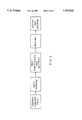
- FIG. 2 is a block flow diagram of continuous filament production.
- FIG. 3 is a graphical representation of fiber tensile strength versus temperature.
- FIG. 4 is a graphical representation of the Youngs' Modulus of fiber versus temperature.
- FIG. 5 is a graphical representation of stress versus displacement based upon a Three Point Bend Test.
- FIG. 6 is a graphical comparison of flex strength and displacement to 850 psi of glass fibers of the present invention with prior art glass fibers.
- FIG. 7 is a graphical comparison of flex displacement to fracture at room temperature and flex displacement to 860 psi at room temperature of glass fibers of the present invention with prior art glass fibers.
- FIGS. 8A-8D are plurality of graphical representations relating to a series of friction tests performed on friction pads containing 1/4 inch "S" glass fibers.
- FIGS. 9A-9D are plurality of graphical representations relating to a series of friction tests performed on friction pads containing 1/4 inch "E" glass fibers.
- FIGS. 10A-10D are plurality of graphical representations relating to a series of friction tests performed on friction pads containing the high temperature glass fibers of the present invention.
- FIGS. 11A-11D are plurality of graphical representations relating to a series of friction tests performed on friction pads containing standard refractory ceramic fibers.
- FIGS. 12A-12D are plurality of graphical representations relating to a series of friction tests performed on friction pads containing another type of standard refractory ceramic fibers.
- the present invention is directed to the preparation of improved glass fibers for applications which include insulation and reinforcement of various matrices, the improvement comprising increased strength properties, improved shrinkage characteristics, and the preparation of these glass fibers with an upper use temperature limit equivalent to refractory ceramic fiber of 2300° F. but in a continuous form, through an economical direct melt method.
- the inorganic feed compounds are commercially available in reagent and technical grade, for example silica, high quality calcined alumina, magnesia and rutile titania, from a number of domestic supplies.
- the continuous filament glass fibers prepared using inorganic compounds in the above composition ranges can be produced by conventional melt drawing techniques.
- continuous filament fibers with preferred compositions within the above range have physical properties such as tensile strength, Young 's modulus, and thermal shrinkage performance, such as exhibited in testing at 2300° C. for 24 hours, which are improved over traditional refractory ceramic fibers.
- TiO x such as TiO 2
- at preferred low percentages of about 1 mole % to about 2 mole %, and most preferably 1.25 mole % to about 1.5 mole % provides an increase in the upper use temperature limit of produced fibers, namely in beneficial low shrinkage characteristics for the produced fibers.
- FIG. 1 is a molar composition diagram of glass components SiO 2 , Al 2 O 3 and MgO projected on a 0% titania plane.
- FIG. 1 details drawable glass fiber compositions in the lightly shaded area, and preferred drawable compositions containing 1.5% titania which particularly yield target properties in terms of improved strength and improved shrinkage characteristics in the dark shaded area.
- target properties with regard to improved strength are generally defined as tensile strength greater than about 250 Ksi and Young's modulus greater than about 12 Msi.
- the target property with regard to improved shrinkage characteristics is generally defined as less than about 3% shrinkage at 2300° F. for 24 hours.
- the lightly shaded area of FIG. I which lies within the compositional ranges of the glass ceramic components detailed above generally corresponds to the preferred ranges of those components, and the dark shaded area of FIG. 1 generally corresponds to the most preferred ranges of those components.
- compositions of high temperature stable continuous filament glass fibers of the present invention comprise
- ZrO 2 has been found useful in obtaining high tensile strength.
- compositions are preferred for continuous filament glass fibers, such compositions display improved properties when utilized in discontinuous high temperature stable glass fibers, also.
- FIG. 2 is a block flow diagram of continuous filament production.
- the major steps in continuous filament production include preparation of a ceramic powder feed, introduction of the powder feed into a melt furnace, melt conditioning (such as fining) and delivery to the fiber-drawing furnaces, called bushings, from which the filaments are drawn, followed by sizing and winding of the fibers.
- Stage 1 consists of the actual glass manufacture, the fusion of selected raw materials in a melt furnace and delivery to the fiber-drawing furnaces.
- Stage 2 consists of the conversion of the glass into fibers in the fiber-drawing furnace, called the bushing.
- Continuous glass fibers are prepared through the rapid mechanical attenuation of molten drops of glass exuding from a large number of nozzles, usually about 200, located on the underside of the bushing which is usually electrically heated. Molten glass exudes from each nozzle where the glass forms a meniscus during fiber-drawing as a result of the mechanical attenuation.
- the individual fibers pass over an applicator which deposits a protecting and lubricating size onto the filaments before they are gathered into bundles of filaments called strands.
- the strands then pass through a light water spray on their way to the winder, which consists of a slightly expandable rotating cylinder, called a collet, covered during the winding process by a removable plastic or paper tube onto which the strand is wound, and a device which lays successive lengths of strands onto the tube at small angles to one another to facilitate subsequent unwinding.
- Stage 3 consists of the conversion of the glass fibers into products.
- Compositions of the present invention have melting points and drawing temperatures between about 1500° C. and about 2000° C. depending upon the specific component ranges utilized. Since the melting points and drawing temperatures are in excess of 1500° C. high temperature melting and drawing equipment are utilized in the manufacture of filaments according to the present invention. Other than the use of high temperature materials of construction, the actual melting and drawing of the filaments by the method of the present invention is accomplished following techniques known to those skilled in the art for melting and drawing of conventional fiberglass.
- compositions of the present invention demonstrate improved properties over traditional refractory ceramic fibers, when manufactured as continuous refractory ceramic fibers by sol-gel methods, as well as refractory ceramic fibers manufactured by traditional blowing or spinning methods, or any other method known to those skilled in the art.
- Manufacture of high temperature stable continuous glass filaments according to the present invention results in increased fiber diameter, relative to standard aluminosilicate materials, when produced using a blowing fiberization technique.
- the ability to control fiber diameter, especially the ability to control fiber diameters to larger values, is beneficial from the aspect of physiological concerns as well as for certain thermal and reinforcement performance.
- compositions of the present invention demonstrate, within a preferred range of about 1 mole % to about 2 mole % TiO 2 in the overall composition and a most preferred range of about 1.25 to about 1.5 mole % TiO 2 , a beneficial effect of low shrinkage characteristics for produced filaments.
- the reason for the improvement in shrinkage characteristics is not completely understood. While not being bound by theory, it is believed that the decreased shrinkage is due to a change in micro-structure within the fiber, from an essentially amorphous structure to a nucleated structure which readily crystallizes when reheated. This theory, however, has not been confirmed by detailed analysis.
- the desired properties of the continuous filament glass fibers of the present invention can be enhanced when at least a portion of the titanium utilized in the melt is in a reduced form as compared to TiO 2 .
- This can be accomplished by a variety of methods.
- One method is to utilize a form of titanium oxide other than, or in addition to, an appropriate portion of titanium dioxide (+4 oxidation state) in the melt. Such other forms include TiO (+2 oxidation state) and Ti 2 O 3 (+3 oxidation state).
- Another method is to introduce at least a portion of the titanium component into the melt in the form of metallic titanium.
- a further method is to add other reducing agents into the melt (or furnace), such as carbon or carbon monoxide, or to use a furnace with a reducing environment, such as a graphite furnace.
- the high temperature stable continuous filament glass fibers of the present invention demonstrate many advantages over traditional refractory ceramic fiber in discontinuous form. These advantages include, but are not limited to, the elimination of shot, the ability to chop filaments to any desired length(s), the ability to utilize the filaments directly for the manufacture of textile products, and the ability to custom manufacture fibers of known diameter.
- Shot refers to high density, unfiberized particles which are detrimental to thermal efficiency, act as stress risers in reinforcing applications, and cause excessive wear in friction applications.
- the elimination of shot in the production of the continuous filament glass fibers of the present invention eliminates the necessity of an additional beneficiation step which is often employed in the production of other types of glass fibers in order to remove the deleterious shot from the fibers.
- the average diameter of fibers produced according to the present invention are controllable within a range of about 5 to about 50 microns, and are preferably used in the range of about 5 to about 25 microns.
- the continuous filament glass fibers of the present invention demonstrate an upper temperature use limit significantly higher than that of "E" glass or "S” glass.
- the continuous fibers of the present invention therefore, are suitable for applications which currently use “E” glass or “S” glass while offering greatly improved high temperature stability in those applications.
- the present invention demonstrates the preparation of continuous filament glass fibers with an upper temperature use limit equivalent to refractory ceramic fiber of 2300° F. while utilizing a direct melt method which is more economical than sol-gel methods or post treatment processes.
- the continuous fibers of the present invention therefore, are suitable for applications which currently use traditional refractory ceramic fibers, while offering the improvements attributable to the continuous nature of the fiber and improved economy in those applications, as well as improved physical properties described above.
- the continuous filament glass fibers of the present invention demonstrate high upper use temperature limits and are suitable for use by methods known in the art as insulation materials in a variety of forms, including woven textile products, ropes, braids, boards, papers, blankets, and mats.
- the ability to utilize the continuous filaments of the present invention directly for such processes as weaving and spinning for the manufacture of textile products provides a distinct advantage over the prior art, by eliminating the organic carriers required with traditional refractory ceramic fiber.
- the high temperature stable continuous filament glass fibers of the present invention are suitable for use in the reinforcement of organic matrix materials. Reinforcement of organic matrices by the fibers of the present invention provide improved properties, including increased tensile strength and modulus, increased flexural strength and modulus, and increased deflection temperature under load. Organic matrices containing continuous fiber reinforcement display exceptional mechanical properties and are generally termed advanced composites to distinguish them from chopped-fiber reinforced materials.
- Suitable organic materials for use as matrices in composites reinforced by the fibers of the present invention are generally polymeric materials of two broad classifications, thermoplastics and thermosets.
- Thermoplastics are polymeric materials which reversibly pass into a plastic state when heated and into a hardened state when cooled.
- Thermosets are polymeric materials which pass once through a plastic state and then harden irreversibly due to the formation of crosslinks.
- thermoplastic polymers suitable for use in fiber-reinforced composite materials include, but are not limited to, polyamides such as nylon-6,6 and nylon-6, polyolefins such as polyethylene and polypropylene, polycarbonates, polyacetals, polystyrene, polysulfones, polyphenylene sulfide, and essentially linear polyesters and polyurethanes.
- thermoset polymers suitable for use in fiber-reinforced composite materials include, but are not limited to, alkyd resins, diallyl ortho-phthalate resins, epoxy resins, phenolic resins, melamine resins, urea resins, silicone resins, polyester resins, and urethane resins.
- the high temperature stable continuous filament glass fibers of the present invention are suitable for use in the reinforcement of matrices of carbonized carbonaceous binders, otherwise known as carbon bodies, produced conventionally. These carbon bodies are useful for a wide variety of applications, wherever strong lightweight bodies are needed, and are especially useful in friction applications.
- One such application is as friction pads for use in brakes, and particularly as friction pads for use in disc brakes, by virtue of the high heat capacity, high strength, high temperature stability, and high coefficient of friction of the glass fiber-reinforced carbon bodies.
- the continuous nature of the high temperature glass fibers of the present invention allows them to be successively circumferentially wound, axially compressed, and radially overlapped in order to prevent failure mechanisms due to improper orientation of the reinforcing fibers.
- the continuous filament glass fibers of the present invention are useful for other friction applications, ranging from automotive to severe duty, when used with conventional binders such as phenolics, fillers, and friction modifiers, if any.
- Loading levels of the high temperature stable glass fiber of the present invention in a matrix material may range from about 1% to about 50% by weight, more preferably, from about 2% to about 30% by weight, and even more preferably, from about 5% to about 20% by weight. It will also be appreciated that the high temperature stable glass fiber may be employed with other glass fibers such as "E" glass to give the matrix material additional strength at certain service temperatures.
- the high temperature glass fibers of the present invention have been found to have particular application in friction pads. That is, friction pads made from a reinforced matrix material which has been reinforced with reinforcement material containing the continuous filament glass fibers of the present invention have been found to exhibit improved flexural strength and improved displacement as compared to friction pads containing "S" glass or "E” glass reinforcement.
- the matrix materials reinforced with the glass fibers of the present invention which form the friction pads have been found to be very strong, very tough composites, exhibiting flexural strength which is twice as high as composites using "E” glass or rockwool. Without being limited to theory, we believe that this result is a function of the improved modulus of the glass fibers of the present invention as compared to "E" glass.
- composition of the fiber of the present invention for these tests fall within the ranges specified hereinabove and specifically include the following: about 72 mole % SiO 2 , about 13 mole % Al 2 O 3 , about 13.5 mole % MgO, and about 1.5 mole % TiO 2 .
- the fibers were substantially uniform 1/4 inch, chopped fibers in hard bundles, and 8 microns in diameter. "Hard bundle” refers to the sizing used to hold the bundle of fibers together. Those that are designed to maintain their integrity after chopping are considered “hard”, while those designed to fall apart after chopping are considered “loose”.
- Preferred lengths for the chopped fibers of the present invention range from about 1/16 of an inch to about 3/4 of an inch, with about 1/16-inch to about 1/4-inch being most preferred.
- FIG. 5 depicts the results of a three point bend test comparison among four brake pad formulations, including a formulation containing the fibers of the present invention.
- This three point bend test which is well known in the friction industry and can be performed by those skilled in the art without undue experimentation, generally takes a predetermined, elongated segment of the brake composite and places it onto a test apparatus which pushes on one side at a point in the middle of the elongated segment while holding the other side at points on the segment's ends.
- the amount of applied stress (in psi) or Modulus of Rupture (MOR) is graphed versus displacement (in inches). Displacement identifies the amount of bend of the segment before rupture.
- the segment of the brake composite containing the chopped, continuous fibers of the present invention (e.g., 1/4" hard bundle continuous filament) was able to handle significantly more applied stress and exhibited a significant increase in displacement as compared to 1/4" and 1/8" "E” glass, rockwool, and even "E” glass formulations having three times higher "E” glass loadings in the segment.
- FIG. 6 is another comparison among various friction pad formulations, including a formulation containing the fibers of the present invention, denoted as “CRF” in the FIG.
- the graph in this FIG. compares flexural strength in psi, denoted as “Series 1" in the graph, and displacement (in inches) to 850 psi, denoted as “Series 2" in the graph.
- the friction composite containing matrix material reinforced with the fibers of the present invention showed significant improvement in flex strength over each of the other friction composites using different reinforcement materials, such as rockwool or "E" glass, even when these composites were loaded at two or three times higher levels of the particular reinforcement material.
- the friction composite utilizing the continuous fibers of the present invention exhibited a flexural strength of almost 8000 psi, whereas the next closest composite, one having a three times higher "E" glass loading, exhibited a flexural strength of only about 5000 psi.
- the glass fibers of the present invention appear to be effective in providing reinforcement to matrix material in friction pads and exhibiting flexural strength of well over 5000 psi, and even above 7000 psi.
- the friction composite containing matrix material reinforced with the glass fibers of the present invention showed significant improvement in that characteristic as well. Displacement was increased significantly to over 0.16 inches as compared to the composites utilizing fibers of the prior art which exhibited displacements of less than 0.10 in most instances.
- the glass fibers of the present invention appear to be effective in providing reinforcement to matrix material in friction pads and increasing displacement to well over 0.10 inches, and even above 0.14 inches at 850 psi.
- FIG. 7 shows still another comparison among various friction pad formulations, including a formulation containing the continuous fibers of the present invention, denoted as "CRF" in the FIG.
- CPF continuous fibers of the present invention
- This FIG. compares displacement (in inches) of the friction composites to fracture when flexed at room temperature and displacement (in inches) of the composites to 860 psi when flexed at room temperature, the composites being molded at 6000 pal.
- the reinforcement materials used included rockwool, "E” glass and the fiber of the present invention. 1/4 inch and 1/8 inch chopped "E” glass fibers used with phenolic binder was used as the baseline formulation.
- the friction composite containing matrix material reinforced with the glass fibers of the present invention showed a significant increase in displacement to fracture and displacement to 860 psi as compared to friction composites containing matrix material reinforced with other fibers, even those having two to three times higher loadings.
- Displacement to fracture of CRF was over 0.04 inches as compared to the other fibers where displacement to fracture was closer to about 0.02 inches.
- Displacement to 860 psi was increased significantly to over 0.18 inches as compared to the composites utilizing fibers of the prior art which exhibited displacements of less than 0.1 in most instances.
- the continuous fibers of the present invention appear to be effective in providing reinforcement to matrix material in friction pads and increasing displacement to well over 0.10 inches, and even above 0.18 inches at 860 psi.
- FIGS. 8A-8D to 12A-12D compare a series of friction tests performed on friction pads made from matrix material reinforced with various glass and ceramic fibers. Specifically, the friction pad/brake formulations included the following material at the following load levels.
- FIG. 8A-8D are uses a friction pad containing 1/4 inch "S" glass fibers;
- FIG. 9 use a friction pad containing 1/4 inch "E” glass;
- FIGS. 10A-10D use a friction pad containing the glass fiber of the present invention;
- FIG. 11A-11D use a friction pad containing a standard ceramic fiber used in passenger car and light truck disc brake pads;
- FIG. 12A-11D use a friction pad containing another type of ceramic fiber typically used for super heavy duty brakes on heavy trucks and the like.
- the tests were performed on a conventional automotive dynamometer in accordance with Procedure A04F, a well known, documented procedure commonly used in the friction industry for determining various friction characteristics, including pad and rotor wear, brake effectiveness, and fade properties.
- the graphs in the upper right-hand corner of the FIGS. relate to initial wear characteristics in "breaking the brake in,” and allows each friction pad to perform under optimal conditions.
- FIGS. 8B to 12B and 8C to 12C These two very important graphs depict the effectiveness of braking at 30 mph (FIGS. 8B to 12B) and 60 mph (FIGS. 8C to 12C), and, specifically, indicate how much pressure must be applied in a brake line to the friction pad in order to provide a particular deceleration rate.
- the test is run in four stages or efforts, with each friction pad undergoing a predetermined series of extensive steps designed to "age” the friction pad between efforts. Once the friction pad has been properly “aged”, the effectiveness is then tested again and so on. A friction pad is considered effective if it does not degrade with each effort. That is, the line pressure used to reach a particular deceleration rate should preferably remain essentially constant.
- the graphs in FIGS. 8D to 12D show fade and recovery properties.
- the rotor temperature of the brake is increased over a series of braking applications. Upon each application, the amount of applied pressure required to stop is measured. It will be appreciated that, as the temperature increased, the amount of applied pressure also increases. Also, as the temperature increases, the differential between the maximum pressure and minimum pressure also increases.
- the temperature is lower or returned to normal over another series of braking applications.
- the pressure applied to the brakes should return back to where it originally started as quickly as possible.
- FIGS. 8A-8D to 12A-12D Upon review of the FIGS. 8A-8D to 12A-12D it will be appreciated that the friction pad utilizing the continuous filament glass fibers of the present invention (FIGS. 10A-10D exhibited excellent fade and recovery properties which exceeded the fade and recovery properties of the "S" glass and "E” glass fibers (FIGS. 8A-8D to 9A-9D) and which were as good as, if not better than, the fade and recovery properties of the refractory ceramic fibers (FIGS. 11A-11D to 12A-12D).
- the high temperature stable glass fibers of the present invention are effective in reinforcing organic and/or carbon matrix material used in friction pads.
- the fibers are the present invention are particularly suitable for disc brake disc pads for passenger cars and light trucks, but are not necessarily limited thereto, the fibers also being useful in other friction pad applications, including but not limited to clutch friction pads, heavy duty truck brake blocks, and brake shoes for drum brakes.
- Continuous filament glass fibers were prepared according to the general procedure detailed in FIG. 2, a block flow diagram which outlines the major steps in continuous filament production. Ceramic powder feeds containing the various amounts of inorganic components detailed in the following numbered examples were prepared and introduced into a melt furnace, followed by melt conditioning and delivery to the bushing, followed by sizing and winding of the filaments. Diameters of samples were measured, and the filaments were tested for physical properties. Shrinkage characteristics for some samples were determined at 1800° F. 2100° F. and 2300° F.
- Shrinkage testing included the analysis of one gram of the tested fiber, ground and pressed into a bar. The linear shrinkage of the bars was measured with vernier calipers cold and then after heating at temperature. This method was confirmed by conducting the test on control K spun fibers and comparing the shrinkage of the K spun bar to the shrinkage of a blanket consisting of K spun fibers.
- examples 1-30 represent samples wherein the concentration of one or more components falls outside the range of compositions defined by the present invention.
- the designation “RO” stands for metal oxides other than silica and alumina, and this column may alternatively contain designations of the derivation of the particular comparative fibers exemplified.
- Examples 1-3 represent "S" glass and “E” glass compositions. The upper use temperature limits for these samples are much lower than those of the glass fibers of the present invention.
- Examples 4-5 represent conventional refractory ceramic fibers derived from kaolin which contain higher Al 2 O 3 percentages and lower MgO percentages than the fibers of the present invention.
- Examples 6-13 each contain MgO percentages lower than the fibers of the present invention.
- Examples 14-20 contain higher percentages of SiO 2 , and lower percentages of Al 2 O 3 and MgO than the fibers of the present invention.
- Examples 21-22 contain lower Al 2 O 3 percentages than the fibers of the present invention.
- Examples 23-30 contain SiO 2 , Al 2 O 3 , and MgO within the ranges of the fibers of the present invention, but no TiO 2 is contained in any of examples 1-30.
- Examples 1-30 are comparative examples which demonstrate physical properties which are generally poorer than those of the fibers of the present invention. For example, the fibers described in examples 1-30 demonstrate much larger shrinkage percentages than the fibers of the present invention, except for examples 4 and 5 which are more comparable (although these fibers are discontinuous).
- Examples 31-86 of Table I generally comprise all inventive components within the composition ranges defined by the present invention, except for those examples described as K Spun which are derived from kaolin and which were measured as control samples to monitor test accuracy for standard shrinkage properties, and examples 42, 54, and 55 which contain no TiO 2 but are included as additional comparative examples to illustrate the beneficial effect of TiO 2 (that is, "TiO x ”) in the fibers of the present invention.
- Examples whose components fall within the inventive range of compositions described herein demonstrate generally improved physical properties and reduced shrinkage as compared to the comparative examples detailed above.
- examples of glass fibers of the present invention demonstrate increased tensile strength, increased Young's modulus and decreased shrinkage as compared to the comparative examples detailed above.
- Examples 72-74, and 83-86 of the continuous filament glass fibers of the present invention exceed target properties with regard to improved strength, with values for tensile strength generally greater than 250 Ksi and Young's modulus generally greater than 12 Msi.
- Target properties for improved linear thermal shrinkage characteristics are demonstrated by examples 31-33, 37-39, 48-50, 51-53, 56-58, 62-65, 66-67, 68-70, 77-81, and 83-86 with values of less than 3% shrinkage at 2300° F. for 24 hours.
- Example 44 shows that a lower level of TiO 2 is not as effective in reducing shrinkage (11.2% shrinkage) as the higher levels of examples 49 and 57 (1.6% shrinkage).
- Example 57 also illustrates the beneficial effect of the addition of 2% TiO 2 when compared to comparative example 54, without TiO 2 , which demonstrates 18.8% shrinkage.
- the data for tensile strength tests and Youngs' modulus determinations are graphically represented in FIG. 3 and FIG. 4 respectively.
- the benefit of the inventive glass fiber compositions is demonstrated by the maintenance of tensile strength at high temperatures.
- the slope of the strength curve of the inventive fiber decreases the least at high temperatures, and in fact, the inventive fiber has the highest strength at 750° C. of any of the fibers tested.
- the slopes of the strength curves of the S glass fibers were compared to a curve of the experimental data reported by Harris et al in U.S. Pat. No. 3,402,055 described above, and were found to coincide, thereby validating the test protocol.
Landscapes
- Chemical & Material Sciences (AREA)
- Life Sciences & Earth Sciences (AREA)
- Engineering & Computer Science (AREA)
- Chemical Kinetics & Catalysis (AREA)
- General Chemical & Material Sciences (AREA)
- Geochemistry & Mineralogy (AREA)
- Materials Engineering (AREA)
- Organic Chemistry (AREA)
- Glass Compositions (AREA)
Abstract
Description
______________________________________
SiO.sub.2       62-85,
Al.sub.2 O.sub.3
                9.5-20,
MgO             5-15.5,
TiO.sub.x       0.5-5, (wherein 0 ≦ x ≦ 2),
ZrO.sub.2       0-5.
______________________________________
______________________________________
SiO.sub.2
         about        62-85,
Al.sub.2 O.sub.3
         about        9.5-20,
MgO      about        5-15.5,
TiO.sub.x
         about        0.5-5 (wherein 0 ≦ x ≦ 2),
ZrO.sub.2
         about        0-5.
______________________________________
______________________________________
Material             Loading Level (Wt. %)
______________________________________
Calcuim Carbonate    40.6
Barium Sulfate       15.2
Phenolic Resin (Cardolite NC-126)
                     15.2
Cashew Particle (10A40)
                     15.2
Aromatic Polyamide Fiber (Kevlar ®)
                     3.8
Fiber                10.0
______________________________________
TABLE I
__________________________________________________________________________
Diam. Tensile
Mod
EX.
(micron)
(KSI) (MSI) Shrinkage Composition Mole %
NO.
Mean
Std.
Mean
Std.
Mean
Std.
2300° F.
2100° F.
1800° F.
SiO.sub.2
Al.sub.2 O.sub.3
RO
__________________________________________________________________________
1 10.2
0.73
340.2
79.8
9.5
0.8
12.1 12.3 13.6 68.6
15.6
15.8 MgO (S-glass)
2 16.0 106.0
15.3
10.3
0.8 57.4
9.1 33.5 (E-glass)
3 11.2
0.83
231.8
43.2
8.8
0.3 57.4
9.1 33.5 (E-glass)
4 8.6
3.49
164.2
59.1
9.2
2.3
3.4 2.1 0.9 66.7
30.0
3.0 (Kspun)
5 13.4
4.28
173.7
71.9
9.4
2.6 66.7
30.0
3.0 (Kspun)
6 11.5
0.87
147.3
49.9
5.9
1.6 86.3
10.5
3.2 CaO
7 14.8
1.32
141.0
37.8
8.8
1.6 15.1 9.0 86.3
10.5
3.2 CaO
8 10.7
3.95
134.7
39.4
8.2
1.5 86.3
10.5
3.2 CaO
9 9.6
0.67
175.3
72.5
9.3
1.6 86.3
10.5
3.2 MgO
10 9.3
0.89
201.7
70.3
10.4
2.6 86.3
10.5
3.2 MgO
11 9.3
0.81
175.2
47.9
9.6
1.5
8.8 0.6 86.3
10.5
3.2 MgO
12 10.2
0.29
193.4
64.8
9.8
0.8
15.3 17.0 2.0 86.3
10.5
3.2 BaO
13 9.6
1.38
138.8
43.1
9.1
0.7 5.0 89.0
10.0
1.0 CaO
14 7.5
0.64
161.6
46.4
9.9
3.3 90.5
5.2 4.3 ZrO.sub.2
15 10.0
0.98
155.8
62.9
10.2
1.5 90.5
5.2 4.3 ZrO.sub.2
16 12.1
0.89
92.9
30.3
8.1
1.6 90.5
5.2 4.3 TiO.sub.2
17 13.7
0.51
120.7
42.9
9.0
0.9
5.4 3.6 90.5
5.2 4.3 TiO.sub.2
18 15.0
0.88
102.7
57.8
8.1
1.4
8.2 90.5
5.2 4.3 ZrO.sub.2
19 19.7
1.94
83.3
27.0
8.0
1.3 90.5
5.2 4.3 ZrO.sub.2
20 11.7
0.75
114.8
40.3
9.5
1.7 90.5
5.2 4.3 TiO.sub.2
21 10.4
1.59
193.1
62.7
10.6
2.4 84.9
7.5 7.6 ZrO.sub.2
22 8.6
1.48
194.3
94.6
11.7
1.5 84.9
7.5 7.6 ZrO.sub.2
23 10.5
0.23
229.3
57.3
11.2
1.2 78.1
13.9
8.0 MgO
24 8.6
0.67
225.6
62.9
10.1
1.6
9.8 8.8 1.4 78.1
13.9
8.0 MgO
25 16.2
1.71
183.9
40.2
10.2
1.1
10.9 10.2 78.1
13.9
8.0 MgO
26 9.6
1.30
169.2
52.9
7.6
1.4
13.4 9.5 1.4 78.0
11.0
9 MgO, 2 ZrO.sub.2
27 6.0
0.25
273.8
69.3
9.3
1.4 78.0
11.0
9 MgO, 2 ZrO.sub.2
28 5.3
0.39
330.3
95.9
11.3
1.7
16.2 11.9 1.4 78.0
11.0
9 MgO, 2 ZrO.sub.2
29 7.1
0.64
271.3
111.3
10.9
1.5 78.0
11.0
9 MgO, 2 ZrO.sub.2
30 11.6
0.38
227.4
53.8
10.8
0.9 78.0
11.0
9 MgO, 2 ZrO.sub.2
31 6.5
0.46
243.9
56.4
11.0
1.4
2.8 1.3 80.1
10.0
8.1 MgO, 1.8 TiO.sub.2
32 6.4
0.31
228.7
67.0
9.7
1.0 80.1
10.0
8.1 MgO, 1.8 TiO.sub.2
33 11.1
0.21
157.2
22.9
10.0
0.7 80.1
10.0
8.1 MgO, 1.8 TiO.sub.2
34 3.1 Kspun
35 8.6
0.41
130.0
33.7
7.7
0.9
4.1 81.6
10.0
6.8 MgO, 1.6 TiO.sub.2
36 3.1 Kspun
37 6.4
0.41
143.9
47.7
8.4
1.1
2.2 78.0
10.0
10.5 MgO, 1.5 TiO.sub.2
38 5.8
0.01
178.9
57.1
9.4
0.4 10.5 MgO, 1.5 TiO.sub.2
39 9.8
0.51
160.3
34.6
7.7
0.8 78.0
11.0
10.5 MgO, 1.5 TiO.sub.2
40 3.4 Kspun
41 9.3
0.30
178.3
36.0
9.1
0.7 78.0
10.0
10.5 MgO, 1.5 TiO.sub.2
42 8.4
0.78
161.0
51.0
8.0
1.3 78.0
11.0
11 Mg0
43 7.1
0.22
270.3
101.4
9.3
0.7 78.0
12.0
9.0 MgO, 1.0 TiO.sub.2
44 13.1
0.23
137.4
83.7
8.8
0.4
11.2 78.0
12.0
9.0 MgO, 1.0 TiO.sub.2
45 9.0
0.20
209.9
94.3
9.2
0.6 78.0
12.0
9.0 MgO, 1.0 TiO.sub.2
46 7.7
0.15
205.9
65.1
9.1
0.5 78.0
12.0
9.0 MgO, 1.0 TiO.sub.2
47 3.0 Kspun
48 5.6
0.18
245.3
52.7
10.2
0.8 78.0
12.3
8.2 MgO, 1.5 TiO.sub.2
49 7.0
0.13
231.5
34.9
10.3
0.5
1.8 78.0
12.3
8.2 MgO, 1.5 TiO.sub.2
50 10.9
0.18
183.3
23.0
10.0
0.3 78.0
12.3
8.2 MgO, 1.5 TiO.sub.2
51 15.1
0.15
204.3
34.4
11.7
0.4 81.0
10.0
7.5 MgO, 1.5 TiO.sub.2
52 9.8
0.11
204.6
36.1
12.0
0.4 81.0
10.0
7.5 MgO, 1.5 TiO.sub.2
53 21.8
0.62
181.5
35.4
10.5
0.4
1.1 81.0
10.0
7.5 MgO, 1.5 TiO.sub.2
54 6.2
0.30
194.0
78.0
8.7
1.0
18.8 78.0
11.0
11 MgO
55 8.7
0.23
181.3
44.0
9.8
0.6 78.0
11.0
11 MgO
56 9.1
0.36
176.8
36.0
9.5
0.8 78.0
10.0
10 MgO, 2 TiO.sub.2
57 11.6
0.39
165.0
28.0
10.0
0.7
1.6 78.0
10.0
10 MgO, 2 TiO.sub.2
58 8.4
0.47
151.0
52.0
8.8
1.1 78.0
10.0
10 MgO, 2 TiO.sub.2
59 10.0
0.12
222.5
47.2
11.6
0.4 81.0
10.0
7.5 MgO, 1.5 TiO.sub.2
60 7.7
0.13
226.3
61.1
11.6
0.4 81.0
10.0
7.5 MgO, 1.5 TiO.sub.2
61 2.4 Kspun
62 7.4
0.14
274.7
81.8
10.2
0.4 79.5
9.5 7.7 MgO, 1.5 TiO.sub.2, 1.8
ZrO.sub.2
63 9.1
0.12
214.9
87.4
10.4
0.3
2.2 79.5
9.5 7.7 MgO, 1.5 TiO.sub.2, 1.8
ZrO.sub.2
64 6.2
0.18
361.0
76.1
10.8
0.7 79.5
9.5 7.7 MgO, 1.5 TiO.sub.2, 1.8
ZrO.sub.2
65 13.2
0.16
179.4
65.4
11.8
0.4 79.5
9.5 7.7 MgO, 1.5 TiO.sub.2, 1.8
ZrO.sub.2
66 7.3
0.12
256.5
96.2
11.3
0.5
1.6 79.5
9.5 7.7 MgO, 1.5 TiO.sub.2, 1.8
ZrO.sub.2
67 9.6
0.13
212.9
68.1
11.6
0.4 79.5
9.5 7.7 MgO, 1.5 TiO.sub.2, 1.8
ZrO.sub.2
68 9.7
0.12
297.4
61.1
11.6
0.4 76.0
11.66
10.84 MgO, 1.5 TiO.sub.2
69 11.8
0.14
266.8
44.9
11.4
0.3
0.8 76.0
11.66
10.84 MgO, 1.5 TiO.sub.2
70 7.1
0.13
286.2
74.0
11.1
0.4 76.0
11.66
10.84 MgO, 1.5 TiO.sub.2
71 2.5 Kspun
72 10.4
0.13
276.0
33.4
12.5
0.4 68.6
15.6
14.3 MgO, 1.5 TiO.sub.2
73 7.6
0.15
293.6
28.1
12.3
0.5
5.7 68.6
15.6
14.3 MgO, 1.5 TiO.sub.2
74 14.6
0.34
218.1
24.9
11.5
0.6 68.6
15.6
14.3 MgO, 1.5 TiO.sub.2
75 10.8 68.6
15.6
15.3 MgO, 0.5 TiO.sub.2
76 2.9 Kspun
77 6.1
0.26
320.0
36.0
11.8
1.2 76.0
11.66
10.84 MgO, 1.5 TiO.sub.2
78 9.4
0.44
270.6
46.2
10.9
0.9 76.0
11.66
10.84 MgO, 1.5 TiO.sub.2
79 14.5
0.65
213.0
36.9
10.5
0.9 76.0
11.66
10.84 MgO, 1.5 TiO.sub.2
80 4.1
0.21
281.0
42.0
10.2
1.0 76.0
11.66
10.84 MgO, 1.5 TiO.sub.2
81 2.5 76.0
11.60
10.84 MgO, 1.5 TiO.sub.2
82 3.3 Kspun
83 1.7 79.5
9.5 7.7 MgO, 1.5 TiO.sub.2, 1.8
ZrO.sub.2
84 6.6
0.23
317.3
100.7
12.2
0.8 79.5
9.5 7.7 MgO, 1.5 TiO.sub.2, 1.8
ZrO.sub.2
85 10.8
0.59
248.7
87.9
13.3
1.5 79.5
9.5 7.7 MgO, 1.5 TiO.sub.2, 1.8
ZrO.sub.2
86 15.3
0.65
177.8
31.8
12.4
0.8 79.5
9.5 7.7 MgO, 1.5 TiO.sub.2, 1.8
ZrO.sub.2
__________________________________________________________________________
                                  TABLE II
__________________________________________________________________________
EX.
   TEST DIAM. (microns)
                TENSILE (KSI)
                        MOD (MSI)
                                COMPOSITION MOLE %
NO.
   TEMP °C.
        MEAN
            STD.
                MEAN
                    STD.
                        MEAN
                            STD.
                                SIO.sub.2
                                   AL.sub.2 O.sub.3
                                       RO
__________________________________________________________________________
87 25.0 15.9
            0.69
                184.8
                    27.6
                        13.7
                            1.2 67.5
                                   15.3
                                       15.5 MgO, 1.5 TiO.sub.2
88 25.0 16.0
            0.54
                190.2
                    35.5
                        13.6
                            0.9 67.5
                                   15.3
                                       15.5 MgO, 1.5 TiO.sub.2
89 260.0
        15.9
            0.43
                181.9
                    44.4
                        13.4
                            0.7 67.5
                                   15.3
                                       15.5 MgO, 1.5 TiO.sub.2
90 500.0
        15.9
            0.53
                177.3
                    30.4
                        13.5
                            1.0 67.5
                                   15.3
                                       15.5 MgO, 1.5 TiO.sub.2
91 750.0
        16.0
            0.50
                121.7
                    23.5
                        11.2
                            0.8 67.5
                                   15.3
                                       15.5 MgO, 1.5 TiO.sub.2
92 25.0 9.6 1.10
                393.4
                    70.6
                        12.5
                            0.6 (S2 COM)
93 25.0 9.2 1.06
                451.7
                    91.5
                        13.6
                            0.6 (S2 COM)
94 260.0
        9.3 0.92
                332.6
                    60.7
                        12.4
                            0.8 (S2 COM)
95 500.0
        9.7 0.59
                333.5
                    56.6
                        12.1
                            0.5 (S2 COM)
96 750.0
        9.7 0.97
                159.0
                    17.4
                        10.1
                            0.6 (S2 COM)
97 25.0 6.5 0.56
                211.9
                    49.2
                        10.6
                            0.7 E Glass (mb)
98 250.0
        6.8 0.44
                223.2
                    68.0
                        10.2
                            0.5 E Glass (mb)
99 500.0
        6.7 0.40
                197.6
                    28.2
                        9.2 0.8 E Glass (mb)
100
   600.0
        6.8 0.49
                152.4
                    25.0
                        8.4 0.7 E Glass (mb)
101
   25.0 8.2 1.39
                366.5
                    46.8
                        12.9
                            0.6 S2 mb
102
   250.0
        8.2 0.72
                294.7
                    56.5
                        12.7
                            0.5 S2 mb
103
   500.0
        8.0 1.02
                299.7
                    60.6
                        12.0
                            0.7 S2 mb
104
   750.0
        8.2 1.20
                141.8
                    40.1
                        9.6 0.9 S2 mb
__________________________________________________________________________
Claims (23)
Priority Applications (1)
| Application Number | Priority Date | Filing Date | Title |
|---|---|---|---|
| US08/768,868 US5767022A (en) | 1994-08-23 | 1996-12-17 | Friction pad containing high temperature stable continuous filament glass fibers |
Applications Claiming Priority (3)
| Application Number | Priority Date | Filing Date | Title |
|---|---|---|---|
| US29425894A | 1994-08-23 | 1994-08-23 | |
| US08/575,060 US5585312A (en) | 1994-08-23 | 1995-12-21 | High temperature stable continuous filament glass ceramic fiber |
| US08/768,868 US5767022A (en) | 1994-08-23 | 1996-12-17 | Friction pad containing high temperature stable continuous filament glass fibers |
Related Parent Applications (1)
| Application Number | Title | Priority Date | Filing Date |
|---|---|---|---|
| US08/575,060 Continuation-In-Part US5585312A (en) | 1994-08-23 | 1995-12-21 | High temperature stable continuous filament glass ceramic fiber |
Publications (1)
| Publication Number | Publication Date |
|---|---|
| US5767022A true US5767022A (en) | 1998-06-16 |
Family
ID=26968433
Family Applications (1)
| Application Number | Title | Priority Date | Filing Date |
|---|---|---|---|
| US08/768,868 Expired - Fee Related US5767022A (en) | 1994-08-23 | 1996-12-17 | Friction pad containing high temperature stable continuous filament glass fibers |
Country Status (1)
| Country | Link |
|---|---|
| US (1) | US5767022A (en) |
Cited By (8)
| Publication number | Priority date | Publication date | Assignee | Title |
|---|---|---|---|---|
| US6193025B1 (en) * | 1997-11-20 | 2001-02-27 | Sumitomo Electric Industries, Ltd. | Disk-brake pad |
| US6668891B2 (en) * | 2001-09-12 | 2003-12-30 | Borgwarner Inc. | Unitary, circumferentially edge wound friction material clutch plate, and method of making same |
| US20090155539A1 (en) * | 2007-12-14 | 2009-06-18 | Douglas Bracher | System, apparatus and method for manufacturing metal ingots |
| EP2380857A1 (en) * | 2010-04-22 | 2011-10-26 | Rockwool International A/S | Friction material comprising chopped continuous mineral fibres |
| US20120247695A1 (en) * | 2011-03-31 | 2012-10-04 | Nichias Corporation | Inorganic fiber paper and method of producing the same |
| US8465825B1 (en) | 2009-05-29 | 2013-06-18 | Hrl Laboratories, Llc | Micro-truss based composite friction-and-wear apparatus and methods of manufacturing the same |
| US8940134B2 (en) * | 2011-04-05 | 2015-01-27 | Nichias Corporation | Paper comprising heat treated bio-soluble inorganic fibers, and method and equipment for making same |
| US9933213B1 (en) | 2008-01-11 | 2018-04-03 | Hrl Laboratories, Llc | Composite structures with ordered three-dimensional (3D) continuous interpenetrating phases |
Citations (20)
| Publication number | Priority date | Publication date | Assignee | Title |
|---|---|---|---|---|
| US3380818A (en) * | 1964-03-18 | 1968-04-30 | Owens Illinois Inc | Glass composition and method and product |
| US3402055A (en) * | 1962-05-25 | 1968-09-17 | Owens Corning Fiberglass Corp | Glass composition |
| US3459568A (en) * | 1965-06-22 | 1969-08-05 | Ppg Industries Inc | High strength fiber glass |
| US3597179A (en) * | 1967-03-30 | 1971-08-03 | Owens Illinois Inc | Glass treatment and glass-ceramic article therefrom |
| US3759353A (en) * | 1970-06-22 | 1973-09-18 | Carborundum Co | Disc brake containing reinforced carbon bodies |
| US3804608A (en) * | 1971-05-24 | 1974-04-16 | Pilkington Brothers Ltd | Method for making glass ceramic materials |
| US3871934A (en) * | 1973-06-28 | 1975-03-18 | Carborundum Co | Resurfacing brake discs |
| US4036654A (en) * | 1972-12-19 | 1977-07-19 | Pilkington Brothers Limited | Alkali-resistant glass compositions |
| US4078939A (en) * | 1975-06-28 | 1978-03-14 | Bayer Aktiengesellschaft | Reinforcing glass fibers of ZnO-MgO-Al2 O3 -SiO2 -TiO2 |
| US4102692A (en) * | 1975-07-23 | 1978-07-25 | Bayer Aktiengesellschaft | Reinforcing glass fibers of MgO-CaO-ZnO-Al2 O3 -SiO2 -TiO2 |
| US4140506A (en) * | 1977-04-06 | 1979-02-20 | Owens-Corning Fiberglas Corporation | Method for processing glass in forming fibers |
| US4159205A (en) * | 1976-07-23 | 1979-06-26 | The Carborundum Company | Process for producing polycrystalline oxide fibers |
| US4277269A (en) * | 1979-12-19 | 1981-07-07 | Kennecott Corporation | Process for the manufacture of ceramic oxide fibers from solvent solution |
| US4379111A (en) * | 1979-05-21 | 1983-04-05 | Kennecott Corporation | Method for producing chromium oxide coated refractory fibers |
| US4492722A (en) * | 1983-07-25 | 1985-01-08 | Owens-Corning Fiberglas Corporation | Preparation of glass-ceramic fibers |
| US4558015A (en) * | 1983-04-22 | 1985-12-10 | Manville Service Corporation | Chemically resistant refractory fiber |
| US4582748A (en) * | 1984-01-26 | 1986-04-15 | Owens-Corning Fiberglas Corporation | Glass compositions having low expansion and dielectric constants |
| US4868142A (en) * | 1987-12-16 | 1989-09-19 | Stemcor Corporation | Method of manufacturing a molten metal-resistant ceramic fiber composition |
| US5064785A (en) * | 1989-08-23 | 1991-11-12 | Nippon Electric Glass Co., Ltd. | Alkali-resistant glass for forming glass fibers |
| US5585312A (en) * | 1994-08-23 | 1996-12-17 | Unifrax Corporation | High temperature stable continuous filament glass ceramic fiber |
-
1996
- 1996-12-17 US US08/768,868 patent/US5767022A/en not_active Expired - Fee Related
Patent Citations (20)
| Publication number | Priority date | Publication date | Assignee | Title |
|---|---|---|---|---|
| US3402055A (en) * | 1962-05-25 | 1968-09-17 | Owens Corning Fiberglass Corp | Glass composition |
| US3380818A (en) * | 1964-03-18 | 1968-04-30 | Owens Illinois Inc | Glass composition and method and product |
| US3459568A (en) * | 1965-06-22 | 1969-08-05 | Ppg Industries Inc | High strength fiber glass |
| US3597179A (en) * | 1967-03-30 | 1971-08-03 | Owens Illinois Inc | Glass treatment and glass-ceramic article therefrom |
| US3759353A (en) * | 1970-06-22 | 1973-09-18 | Carborundum Co | Disc brake containing reinforced carbon bodies |
| US3804608A (en) * | 1971-05-24 | 1974-04-16 | Pilkington Brothers Ltd | Method for making glass ceramic materials |
| US4036654A (en) * | 1972-12-19 | 1977-07-19 | Pilkington Brothers Limited | Alkali-resistant glass compositions |
| US3871934A (en) * | 1973-06-28 | 1975-03-18 | Carborundum Co | Resurfacing brake discs |
| US4078939A (en) * | 1975-06-28 | 1978-03-14 | Bayer Aktiengesellschaft | Reinforcing glass fibers of ZnO-MgO-Al2 O3 -SiO2 -TiO2 |
| US4102692A (en) * | 1975-07-23 | 1978-07-25 | Bayer Aktiengesellschaft | Reinforcing glass fibers of MgO-CaO-ZnO-Al2 O3 -SiO2 -TiO2 |
| US4159205A (en) * | 1976-07-23 | 1979-06-26 | The Carborundum Company | Process for producing polycrystalline oxide fibers |
| US4140506A (en) * | 1977-04-06 | 1979-02-20 | Owens-Corning Fiberglas Corporation | Method for processing glass in forming fibers |
| US4379111A (en) * | 1979-05-21 | 1983-04-05 | Kennecott Corporation | Method for producing chromium oxide coated refractory fibers |
| US4277269A (en) * | 1979-12-19 | 1981-07-07 | Kennecott Corporation | Process for the manufacture of ceramic oxide fibers from solvent solution |
| US4558015A (en) * | 1983-04-22 | 1985-12-10 | Manville Service Corporation | Chemically resistant refractory fiber |
| US4492722A (en) * | 1983-07-25 | 1985-01-08 | Owens-Corning Fiberglas Corporation | Preparation of glass-ceramic fibers |
| US4582748A (en) * | 1984-01-26 | 1986-04-15 | Owens-Corning Fiberglas Corporation | Glass compositions having low expansion and dielectric constants |
| US4868142A (en) * | 1987-12-16 | 1989-09-19 | Stemcor Corporation | Method of manufacturing a molten metal-resistant ceramic fiber composition |
| US5064785A (en) * | 1989-08-23 | 1991-11-12 | Nippon Electric Glass Co., Ltd. | Alkali-resistant glass for forming glass fibers |
| US5585312A (en) * | 1994-08-23 | 1996-12-17 | Unifrax Corporation | High temperature stable continuous filament glass ceramic fiber |
Non-Patent Citations (26)
| Title |
|---|
| Cheng, Y. et al The Behavior of ZrO 2 in Y 2 O 3 Al 2 O 3 SiO 2 Glasses, Br. Ceram, Trans. J., 87, 107 110, (1988). * |
| Cheng, Y. et al The Behavior of ZrO2 in Y2 O3 -Al2 O3 -SiO2 Glasses, Br. Ceram, Trans. J., 87, 107-110, (1988). |
| Hayashi, K. et al, Densification of Compacted Magnesium Alumino Silicate Glass Powders, Journal of the Ceramic Society of Japan, Int. Edition, vol. 98 1077, 11 16 (1990). * |
| Hayashi, K. et al, Densification of Compacted Magnesium Alumino--Silicate Glass Powders, Journal of the Ceramic Society of Japan, Int. Edition, vol. 98-1077, 11-16 (1990). |
| Kajiwara, M., Formation and Crystallisation of Al 2 O 3 TiO 2 SiO 2 glasses, Glass Technology vol. 29 No. 5, Oct. 1988, 188 192. * |
| Kajiwara, M., Formation and Crystallisation of Al2 O3 -TiO2 -SiO2 glasses, Glass Technology vol. 29 No. 5, Oct. 1988, 188-192. |
| Lambertson, W.A. et al, Continuous Filament Ceramic Fibers, WADD Technical Report 60 244, (1960) 19 51, 57 59. * |
| Lambertson, W.A. et al, Continuous Filament Ceramic Fibers, WADD Technical Report 60-244, (1960) 19-51, 57-59. |
| Lowenstein, K.L. et al, The Manufacturing Technology of Continuous Glass Fibres, 2nd. Ed. (Elsevier, 1983) 32 55. * |
| Lowenstein, K.L. et al, The Manufacturing Technology of Continuous Glass Fibres, 2nd. Ed. (Elsevier, 1983) 32-55. |
| Maier, V. et al, Nucleation and Crystallization in Mg Al silicate glass ceramics, Cfi/Ber.DKG 6/7 (1988), pp. 208 212. * |
| Maier, V. et al, Nucleation and Crystallization in Mg-Al silicate-glass-ceramics, Cfi/Ber.DKG 6/7 (1988), pp. 208-212. |
| Murakami, Y. et al, Phase Equilibria in the Al 2 O 3 Y 2 O 3 SiO 2 System, and Phase Separtaion and Crystallization Behavior of Glasses, Journal of the Ceramic Society of Japan. Int. Edition, vol. 99 210 216, (1990). * |
| Murakami, Y. et al, Phase Equilibria in the Al2 O3 -Y2 O3 -SiO2 System, and Phase Separtaion and Crystallization Behavior of Glasses, Journal of the Ceramic Society of Japan. Int. Edition, vol. 99--210-216, (1990). |
| Robinson, J.W. et al, Ceramic Fibers for friction applications, Automotive Engineering, vol. 98,No. 12, (1990) 47 52. * |
| Robinson, J.W. et al, Ceramic Fibers for friction applications, Automotive Engineering, vol. 98,No. 12, (1990) 47-52. |
| Shyu, J. et al, Effect of TiO 2 addition on the nucleation of apatite in MgO CaO SiO 2 P 2 O 5 glass, Journal of Materials Science Letters, 10 (1991), 1056 1058. * |
| Shyu, J. et al, Effect of TiO2 addition on the nucleation of apatite in MgO-CaO-SiO2 -P2 O5 glass, Journal of Materials Science Letters, 10 (1991), 1056-1058. |
| Sue, Y. et al, Spheurulitic growth from a phase separated Vitreous Matrix in a Cordierite Y Stabilized Ziroconia glass Ceramic, J. Am. Ceram. Soc., 74 1 85 91 (1991). * |
| Sue, Y. et al, Spheurulitic growth from a phase-separated Vitreous Matrix in a Cordierite-Y-Stabilized Ziroconia glass-Ceramic, J. Am. Ceram. Soc., 74 1! 85-91 (1991). |
| Sue, Y. et al, Surface nucleation and cellular growth kinetics of cordierite glass ceramics containing 3 mol % Y 2 O 3 ZrO 2 , Journal of Materials Science 26 (1991) 1699 1704. * |
| Sue, Y. et al, Surface nucleation and cellular growth kinetics of cordierite glass ceramics containing 3 mol % Y2 O3 --ZrO2, Journal of Materials Science 26 (1991) 1699-1704. |
| Vogel, W. et al, Nucleation and crystallization kinetics of an MgO Al 2 O 3 SiO 2 base glass with various dopants, pp. 125 145. * |
| Vogel, W. et al, Nucleation and crystallization kinetics of an MgO-Al2 O3 -SiO2 base glass with various dopants, pp. 125-145. |
| Wallenberger, F. et al, Inviscid Melt Spinning of Alumina Fibers Chemical Jet Stabilization, J. Am. Ceram. Soc., 75 3 629 636 (1992). * |
| Wallenberger, F. et al, Inviscid Melt Spinning of Alumina Fibers--Chemical Jet Stabilization, J. Am. Ceram. Soc., 75 3! 629-636 (1992). |
Cited By (11)
| Publication number | Priority date | Publication date | Assignee | Title |
|---|---|---|---|---|
| US6193025B1 (en) * | 1997-11-20 | 2001-02-27 | Sumitomo Electric Industries, Ltd. | Disk-brake pad |
| US6668891B2 (en) * | 2001-09-12 | 2003-12-30 | Borgwarner Inc. | Unitary, circumferentially edge wound friction material clutch plate, and method of making same |
| US20090155539A1 (en) * | 2007-12-14 | 2009-06-18 | Douglas Bracher | System, apparatus and method for manufacturing metal ingots |
| US8517083B2 (en) | 2007-12-14 | 2013-08-27 | Refractory Specialties, Incorporated | System, apparatus and method for manufacturing metal ingots |
| US9933213B1 (en) | 2008-01-11 | 2018-04-03 | Hrl Laboratories, Llc | Composite structures with ordered three-dimensional (3D) continuous interpenetrating phases |
| US8465825B1 (en) | 2009-05-29 | 2013-06-18 | Hrl Laboratories, Llc | Micro-truss based composite friction-and-wear apparatus and methods of manufacturing the same |
| EP2380857A1 (en) * | 2010-04-22 | 2011-10-26 | Rockwool International A/S | Friction material comprising chopped continuous mineral fibres |
| WO2011131761A1 (en) * | 2010-04-22 | 2011-10-27 | Rockwool International A/S | Friction material comprising chopped continuous mineral fibres |
| US20120247695A1 (en) * | 2011-03-31 | 2012-10-04 | Nichias Corporation | Inorganic fiber paper and method of producing the same |
| US8641868B2 (en) * | 2011-03-31 | 2014-02-04 | Nichias Corporation | Inorganic fiber paper and method of producing the same |
| US8940134B2 (en) * | 2011-04-05 | 2015-01-27 | Nichias Corporation | Paper comprising heat treated bio-soluble inorganic fibers, and method and equipment for making same |
Similar Documents
| Publication | Publication Date | Title |
|---|---|---|
| US5585312A (en) | High temperature stable continuous filament glass ceramic fiber | |
| US6030910A (en) | High temperature resistant glass fiber | |
| US5874375A (en) | High temperature resistant glass fiber | |
| US6953757B2 (en) | High temperature a resistant vitreous inorganic fiber | |
| US4778722A (en) | Reinforcing fibers and composite materials reinforced with said fibers | |
| US4588699A (en) | High strength, thermally stable magnesium aluminosilicate glass-ceramic matrix-sic fiber composites | |
| US4589900A (en) | High-strength thermally stable magnesium aluminosilicate glass-ceramic matrix sic fiber composite | |
| CA1313721C (en) | Phenolic molding materials and processes | |
| US5767022A (en) | Friction pad containing high temperature stable continuous filament glass fibers | |
| EP0198139A1 (en) | Reinforced alkaline earth aluminosilicate glasses | |
| US4403047A (en) | Asbestos-free friction material | |
| US3812077A (en) | Fiber reinforced composite materials | |
| JPH04224174A (en) | Coated fiber-reinforced material, ceramic composite containing it and method for preparation thereof | |
| US6579616B1 (en) | String binders | |
| US5399440A (en) | Composite material with a glass-ceramic or ceramic matrix obtained by the sol-gel process and reinforced by fibers based on silicon carbide, its manufacture and its applications | |
| EP2380857A1 (en) | Friction material comprising chopped continuous mineral fibres | |
| US5164341A (en) | Fiber reinforced ceramic matrix composites exhibiting improved high-temperature strength | |
| US4976761A (en) | Method for making ceramic matrix composite article | |
| US5350716A (en) | Fiber-reinforced composites | |
| JP3270903B2 (en) | Brake material with high friction coefficient composed of carbon-carbon composite material | |
| US4722864A (en) | Heat-strengthened yarn | |
| AU727752B2 (en) | High temperature resistant glass fiber | |
| JPH0725645A (en) | Fiber reinforced composite material | |
| SU331533A1 (en) | REINFORCED GLASS | |
| JPH06241381A (en) | Heat insulator |
Legal Events
| Date | Code | Title | Description |
|---|---|---|---|
| AS | Assignment |
Owner name: UNIFRAX CORPORATION, NEW YORK Free format text: ASSIGNMENT OF ASSIGNORS INTEREST;ASSIGNORS:CLERE, THOMAS M.;OLSON, JAMES;REEL/FRAME:008466/0834 Effective date: 19970415 |
|
| AS | Assignment |
Owner name: BANK OF AMERICA, N.A., AS ADMINISTRATIVE AGENT FOR Free format text: SECURITY INTEREST;ASSIGNOR:UNIFRAX CORPORATION;REEL/FRAME:011238/0647 Effective date: 20001005 |
|
| FEPP | Fee payment procedure |
Free format text: PAT HOLDER NO LONGER CLAIMS SMALL ENTITY STATUS, ENTITY STATUS SET TO UNDISCOUNTED (ORIGINAL EVENT CODE: STOL); ENTITY STATUS OF PATENT OWNER: LARGE ENTITY |
|
| REFU | Refund |
Free format text: REFUND - PAYMENT OF MAINTENANCE FEE, 4TH YR, SMALL ENTITY (ORIGINAL EVENT CODE: R283); ENTITY STATUS OF PATENT OWNER: LARGE ENTITY |
|
| FPAY | Fee payment |
Year of fee payment: 4 |
|
| SULP | Surcharge for late payment | ||
| AS | Assignment |
Owner name: UNIFRAX CORPORATION, NEW YORK Free format text: RELEASE OF SECURITY INTEREST;ASSIGNOR:BANK OF AMERICA, N.A.;REEL/FRAME:014475/0588 Effective date: 20030905 Owner name: WACHOVIA BANK NATIONAL ASSOCIATION, NORTH CAROLINA Free format text: SECURITY INTEREST;ASSIGNOR:UNIFRAX CORPORATION;REEL/FRAME:014491/0473 Effective date: 20030905 |
|
| FEPP | Fee payment procedure |
Free format text: PAYOR NUMBER ASSIGNED (ORIGINAL EVENT CODE: ASPN); ENTITY STATUS OF PATENT OWNER: LARGE ENTITY |
|
| REMI | Maintenance fee reminder mailed | ||
| LAPS | Lapse for failure to pay maintenance fees | ||
| AS | Assignment |
Owner name: UNIFRAX CORPORATION, NEW YORK Free format text: RELEASE AND ASSIGNMENT OF SECURITY INTEREST;ASSIGNOR:WACHOVIA BANK NATIONAL ASSOCIATION;REEL/FRAME:017882/0263 Effective date: 20050502 |
|
| STCH | Information on status: patent discontinuation |
Free format text: PATENT EXPIRED DUE TO NONPAYMENT OF MAINTENANCE FEES UNDER 37 CFR 1.362 |
|
| FP | Lapsed due to failure to pay maintenance fee |
Effective date: 20060616 |