US5771237A - Multiple rate waveshaping technique for fast ethernet media driver - Google Patents
Multiple rate waveshaping technique for fast ethernet media driver Download PDFInfo
- Publication number
- US5771237A US5771237A US08/590,428 US59042896A US5771237A US 5771237 A US5771237 A US 5771237A US 59042896 A US59042896 A US 59042896A US 5771237 A US5771237 A US 5771237A
- Authority
- US
- United States
- Prior art keywords
- frequency
- transmission data
- waveshape
- transmission
- signals
- Prior art date
- Legal status (The legal status is an assumption and is not a legal conclusion. Google has not performed a legal analysis and makes no representation as to the accuracy of the status listed.)
- Expired - Lifetime
Links
Images


Classifications
-
- H—ELECTRICITY
- H04—ELECTRIC COMMUNICATION TECHNIQUE
- H04L—TRANSMISSION OF DIGITAL INFORMATION, e.g. TELEGRAPHIC COMMUNICATION
- H04L25/00—Baseband systems
- H04L25/02—Details ; arrangements for supplying electrical power along data transmission lines
- H04L25/03—Shaping networks in transmitter or receiver, e.g. adaptive shaping networks
- H04L25/03828—Arrangements for spectral shaping; Arrangements for providing signals with specified spectral properties
- H04L25/03834—Arrangements for spectral shaping; Arrangements for providing signals with specified spectral properties using pulse shaping
-
- H—ELECTRICITY
- H04—ELECTRIC COMMUNICATION TECHNIQUE
- H04L—TRANSMISSION OF DIGITAL INFORMATION, e.g. TELEGRAPHIC COMMUNICATION
- H04L12/00—Data switching networks
- H04L12/28—Data switching networks characterised by path configuration, e.g. LAN [Local Area Networks] or WAN [Wide Area Networks]
- H04L12/40—Bus networks
- H04L12/407—Bus networks with decentralised control
- H04L12/413—Bus networks with decentralised control with random access, e.g. carrier-sense multiple-access with collision detection (CSMA-CD)
Definitions
- the present invention relates to a waveshaping technique, and especially to a multiple rate waveshaping technique for a fast Ethernet media driver.
- the computer or workstation must convert the data into transmission codes according to the communication protocol frequency, and then couple the transmission codes into a transfer medium such as a twisted-pair, etc. Therefore in order to effectively and simply transfer and convert data of different protocols at the physical level of a network for matching different communication protocol frequencies such as 10 Mbps for 10 BASE-T or 125 Mbps for 100 BASE-T, a multiple rate-waveshaping technique for fast ethernet media drivers is needed.
- the multiple rate waveshaping technique for fast ethernet media drivers of the present invention is used to solve this problem.
- the present invention can be used in application, such as transmission between both 10 BASE-T and 100 BASE-T Physical Interface at multiple data rates, 10 Mbps for 10 BASE-T and 125 Mbps for 100 BASE-T.
- the data speed is selectable and so is the waveshape and frequency spectrum content of the transmission waveshape.
- the selectable waveshape can be coupled to the transmission cable for different frequency spectrum requirements of 10 BASE-T and 100 BASE-T Physical Interfaces.
- the multiple rate waveshaping technique for fast ethernet media driver of the present invention is made up of state machines of different frequency, select multiplexers and a set of differential current source drivers.
- the waveshaping technique of the present invention selects a state machine according to the communication protocol frequency. This state machine generates a series of waveshape signals from transmission data and feeds the signals into a current source driver, and then the waveshape signals are coupled with transmission media by the power driver. Therefore the wavefrom generator of the present invention generates multiple rates in a network interface card.
- the state machine is designed to include some pre-stored waveshapes.
- the pre-stored waveshapes is utilized for reducing the EMI (Electronic magnetic interference) by shifting the frequency power spectrum to low frequency without an external Low Pass Filter.
- the waveshapes are determined for any data sequence and variable data rate, and stored in the state machine. By pre-stored the group of current drivers, any waveshapes can be synthesized for different applications.
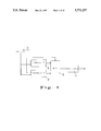
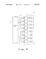
- FIG. 1 is a functional block diagram of the multiple rate waveshaping technique for fast ethernet media drivers of the preferred embodiment of the present invention.
- FIG. 2 shows the state diagram of a state machine which can generate 10 BASE-T Manchester Code.
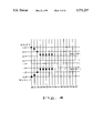
- FIG. 3 shows a predetermined short waveshape used in the state diagram of FIG. 2.
- FIG. 4 shows a predetermined long waveshape used in the state diagram of FIG. 2.
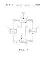
- FIG. 5 shows a waveshape download machine used the 10 BASE-T state machine of FIG. 2.
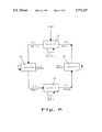
- FIG. 6 is the state diagram of a state machine which can generate 100 BASE-T MLT-3 Code.
- FIG. 7 shows a predetermined waveshape used in the state diagram of FIG. 6.
- FIG. 8 shows a waveshape download machine using the 100 BASE-T state machine of FIG. 6.
- FIG. 9 shows a select multiplexer
- FIG. 10 shows a set of differential current source drivers.
- FIG. 1 is a block diagram of the multiple rate waveshaping technique for fast ethernet media drivers of the preferred embodiment of the present invention.
- the block diagram show of two sets of state machine 1 (10 BASE-T) and 2 (100 BASE-T), a set of select multiplexers 3 (Mux), and a set of differential current source drivers 4 (Drivers).
- the block diagram further show a select signal line 5 (Select) and a sampling pulse CK N:1!.
- the select signal line 5 is used to select the different state machines 1 or 2 of different protocol frequency and provides the select signal to the select multiplex 3; while the sampling pulse provides a reference pulse CK N:1! to the state machine 1 and state machine 2.
- N is selected as 7 in this example.
- FIG. 2 is the diagram of state machine 1 for generating a 10 BASE-T Manchester Code.
- FIG. 3 shows a pre-stored short waveshape used by the state machine of FIG. 2.
- FIG. 4 shows a pre-stored long waveshape used by the state machine of FIG. 2.
- FIG. 5 shows a waveshape download machine used by the state machine.
- the state diagram for the Manchester Code of the present invention comprises 4 states 11, 12, 13, and 14, and 6 pre-stored waveshapes WS-1T1, WS1T-1,WS-1T-.5,WS-.5T1,WS1T.5,WS.5T-1, wherein the 4 states are:
- the waveshape signal comprises two pre-stored short waveshapes WS-1T1, WS1T-1 (referring to FIG. 3).
- the waveshape signal comprises two pre-stored short waveshapes WS1T-1, WS-1T1 (referring to FIG. 3).
- the waveshape signal comprises a long wave containing two pre-stored short waveshapes WS1T.5, WS.5T-1 (referring to FIG. 4).
- the waveshape signal comprises a long wave containing two pre-stored short waveshapes WS-1T-.5, WS.5T1 (referring to FIG. 4).
- the level of the pre-stored 6 waveshapes is as follows.
- WS-1T1 the transmission level is changed from -1 to 1, as shown in the black block section curve of the FIG. 3. In the curve, the transmission level is changed from -1 at time t0 to 1 of time t7 through -0.7, -0.4, 0.4, 0.7, and 0.9 at t2, t3, t4, t5, and t6, respectively.
- WS1T-1 the transmission level is changed from 1 to -1, as shown in the black round point curve of the FIG. 3. In the curve, the transmission level is changed from 1 at time t0 to -1 of time t7 through 0.7, 0.4, -0.4, -0.7, and -0.9 at t2, t3, t4, t5, and t6, respectively.
- WS-1T-.5 the transmission level is changed from -1 to -0.5, as shown in the black block section curve of the FIG. 4. In the curve, the transmission level is changed from -1 at time t0 through -0.7, and -0.5 at t2 and t3, respectively, and then is retained at 0.5 from t4 to t7.
- WS-.5T1 the transmission level is changed from -0.5 to -1, as shown in the white block section curve of the FIG. 4. In the curve, the transmission level is retained at -0.5 through t0 to t3, then it is changed from 0.5 of t4 to 1 at t7 through 0.7 and 0.9 at t5 and t6, respectively.
- WS1T.5 the transmission level which is the front part of a long wave is changed from 1 to 0.5, as shown in the black block section curve of the FIG. 4. In the curve, the transmission level is changed from 1 at time t0 through 0.9, 0.7 and 0.5 at t1, t2 and t3, respectively, and then is retained at 0.5 from t4 to t7.
- WS.5T-1 the transmission level which is the later part of a long wave is changed from 0.5 to -1, as shown in the white block section curve of the FIG. 4. In the curve, the transmission level is retained at 0.5 through t0 to t3, then it is changed from -0.5 of t4 to -1.0 at t7 through -0.7 and -0.9 at t5 and t6, respectively.
- the change for each information in the state diagram of FIG. 2 includes two short waves or half waves. Each of those waves contains the time period from t0 to t7. Because the state machine needs to generate a waveshape of 10 Mbps, the period of each half wave is 50 ns. Therefore, the total time of two half waves is 100 ns so the frequency is exactly equal to 10 Mbps.
- the state machine shown in FIG. 5 comprises a state control section 7 and a waveshape download machine 6, wherein the waveshape download machine downloads the predetermined waveshape into the current source driver 4 by using a D type flip-flop.
- the timing of the download machine 6 is controlled by a sampling pulse CK 7:0!.
- Each one of the set of sampling pulses CK 7:0! is delayed for 50 ns so that it generated a synthesized waveshape with an equal period of 50 ns, while the adjacent pulses, such as CK1, CK2, etc., are separated by 6.25 ns.
- the pulse may be generated by a general circular oscillator of an analog phase-locked loop.
- FIG. 6 shows the state diagram of the state machine 2 which can generate 100 BASE-T MLT-3 Code.
- FIG. 7 shows a pre-stored waveshape used in FIG. 6.
- FIG. 8 shows a waveshape download machine 7 used in the 100 BASE-T state machine 2.
- MLT-3 Code there are four kinds of MLT-3 Code in the present embodiment which form states 21, 22, 23 and 24.
- FIG. 7 there are three types of the pre-stored waveshapes of the state machine 7, including elevating waveshapes, descending waveshapes, and horizontal waveshape.
- the seven pre-stored waveshapes are: WS0T0, WS1T1, WS-1T-1, WS1T0, WS0T1, WS-1T0 and WS0T-1. If the transmission data is 1, MLT-3 Code performs the elevating or descending transformation of 0 to 1, 1 to 0, 0 to -1 or -1 to 0 according the prior condition of the transmission code level (i.e., 0, 1, -1). If the transmission data is 0, the transmission code level state is retained in the original state.
- the level transformation of the seven pre-stored waveshapes is as follows:
- WS0T0 is a waveshape for which the transmission level is retained at 0, for example, the black horizontal line in the upper part of FIG. 7.
- WS1T1 is a waveshape for which the transmission level is retained at 1, for example, the black horizontal line in the middle part of FIG. 7.
- WS-1T-1 is a waveshape for which the transmission level is retained at -1, for example, the black horizontal line in the lower part of FIG. 7.
- WS0T1 is an elevating waveshape for which the transmission level is transmitted from 0 to 1, for example, the white block elevating curve in FIG. 7.
- WS0T-1 is a descending waveshape for which the transmission level is transmitted from 0 to -1, for example, the white block descending curve in FIG. 7.
- WS1T0 is a descending waveshape for which the transmission level is transmitted from 1 to 0, for example, the black circular point descending curve in FIG. 7.
- WS-1T0 is a elevating waveshape for which the transmission level is transmitted from -1 to 0, for example, the black circular point elevating curve in FIG. 7.
- the transmission level is equal to 1. If the transmission datum is 0, the transmission datum is retained as the original form, i.e., the waveshape of WS-1T-1. If the transmission datum is 1, the transmission level is elevated to 0 according to the elevated waveshape WS-1T0 and is changed to the state 22.
- the transmission level is equal to 0. If the transmission datum is 0, the transmission datum is retained as the original form, i.e., the waveshape of WS0T0. If the transmission datum is 1, the transmission level is elevated to 1 according to the elevated waveshape WS0T1 and is changed to the state 23.
- the transmission level is equal to 1. If the transmission datum is 0, the transmission datum is retained as the original form, i.e., the waveshape of WS1T1. If the transmission datum is 1, the transmission level is descended to 0 according to the descended waveshape WS1T0 and is change to the state 24.
- the transmission level is equal to 0. If the transmission datum is 0, the transmission datum is retained as the original form, i.e., the waveshape of WS0T0. If the transmission datum is 1, the transmission level is descended to -1 according to the descended waveshape WS0T-1 and is changed to the state 21.
- each change of the data is generated from one of the predetermined waveshapes. Since the state machine 2 must generate a waveshape of 125 Mbps, the period of each waveshape is equal to 8 ns, which means that the time between t0 and t7 is 8 ns.
- the state machine 2 shown in FIG. 8 includes a state control section 9 and a waveshape download machine 8, in which the waveshape download machine 9 downloads the predetermined waveshape of the state machine 2 into the current source driver 4 by using D type flip-flop.
- the timing of the download machine 8 is controlled by a sampling pulse CK 7:0!.
- Each one of the set of sampling pulses CK 7:0! is delayed for 8 ns so that it generates a synthesized waveshape with equal periods of 8 ns.
- the adjacent pulses such as CK1, CK2, etc., are separated by 1 ns.
- the pulses may be generated by a general circular oscillator of an analog phase-locked loop.
- the select multiplexer 3 in FIG. 9 selects the waveshape signal generated by state machine 1 or state machine 2 according to the select signal line 5 and transfers the signals to the current source driver 4.
- the driver 4 includes eight multiplexers 31 to 38 having two sets of select functions of two to 1.
- the current source driver 4 of FIG. 10 couples the output waveshape signal of the select multiplexers 3 into the transmission media.
- the current source driver 4 contains eight independent current source drivers 41 to 48.
- Various waveshapes are synthesized from the predetermined waveshape signals of state machine 1, 2 as well as current source drivers with different current values.
- Each of the current source drivers 41 to 48 may have different current valves.
- the current source drivers in the embodiment may be changed from eight to ten so to increase the quality of the waveshape, but the number of the current source drivers must match the number of state machines.
- the predetermined waveshapes can be changed to match the communication transmission codes of different communication protocols. Therefore, the invention is not to be limited to the disclosed embodiment, but on the contrary, is intended to cover any modifications and equivalent arrangements included within the spirit and scope of the appended claims.
Abstract
Description
Claims (15)
Priority Applications (1)
| Application Number | Priority Date | Filing Date | Title |
|---|---|---|---|
| US08/590,428 US5771237A (en) | 1996-01-23 | 1996-01-23 | Multiple rate waveshaping technique for fast ethernet media driver |
Applications Claiming Priority (1)
| Application Number | Priority Date | Filing Date | Title |
|---|---|---|---|
| US08/590,428 US5771237A (en) | 1996-01-23 | 1996-01-23 | Multiple rate waveshaping technique for fast ethernet media driver |
Publications (1)
| Publication Number | Publication Date |
|---|---|
| US5771237A true US5771237A (en) | 1998-06-23 |
Family
ID=24362237
Family Applications (1)
| Application Number | Title | Priority Date | Filing Date |
|---|---|---|---|
| US08/590,428 Expired - Lifetime US5771237A (en) | 1996-01-23 | 1996-01-23 | Multiple rate waveshaping technique for fast ethernet media driver |
Country Status (1)
| Country | Link |
|---|---|
| US (1) | US5771237A (en) |
Cited By (12)
| Publication number | Priority date | Publication date | Assignee | Title |
|---|---|---|---|---|
| US5920705A (en) * | 1996-01-31 | 1999-07-06 | Nokia Ip, Inc. | Method and apparatus for dynamically shifting between routing and switching packets in a transmission network |
| US5991303A (en) * | 1997-07-28 | 1999-11-23 | Conexant Systems, Inc. | Multi-rate switching physical device for a mixed communication rate ethernet repeater |
| US6014708A (en) * | 1998-02-19 | 2000-01-11 | Alcatel | Adaptor and method for mapping a fast ethernet payload input signal to a synchronous payload envelope, as well as a clock selector for use therewith |
| US6172634B1 (en) * | 1998-02-25 | 2001-01-09 | Lucent Technologies Inc. | Methods and apparatus for providing analog-fir-based line-driver with pre-equalization |
| US6215816B1 (en) * | 1997-03-04 | 2001-04-10 | Texas Instruments Incorporated | Physical layer interface device |
| US6466626B1 (en) | 1999-02-23 | 2002-10-15 | International Business Machines Corporation | Driver with in-situ variable compensation for cable attenuation |
| US20020191574A1 (en) * | 2001-06-04 | 2002-12-19 | Rebecca S. Taylor | Dynamically extensible communications gateway |
| US20030191883A1 (en) * | 2002-04-05 | 2003-10-09 | Sycamore Networks, Inc. | Interface for upgrading serial backplane application from ethernet to gigabit ethernet |
| US20050005022A1 (en) * | 1999-02-16 | 2005-01-06 | Taylor Rebecca S. | Generic Communications Protocol Translator |
| US20050015535A1 (en) * | 2003-07-14 | 2005-01-20 | Broadcom Corporation | Method and system for addressing a plurality of ethernet controllers integrated into a single chip which utilizes a single bus interface |
| US20100122122A1 (en) * | 2008-11-11 | 2010-05-13 | Realtek Semiconductor Corp. | Wired network connection establishing method and network device for performing the method |
| US20100248774A1 (en) * | 2009-03-24 | 2010-09-30 | Liang-Wei Huang | Power consumption control method of a communication system and related communication system |
Citations (5)
| Publication number | Priority date | Publication date | Assignee | Title |
|---|---|---|---|---|
| US5048055A (en) * | 1990-02-26 | 1991-09-10 | International Business Machines Corporation | Multi-data rate selectable equalizer |
| US5309036A (en) * | 1993-05-28 | 1994-05-03 | Myson Technology Inc. | Driver circuit for an attachment unit interface used in a network system |
| US5357145A (en) * | 1992-12-22 | 1994-10-18 | National Semiconductor Corporation | Integrated waveshaping circuit using weighted current summing |
| US5485488A (en) * | 1994-03-29 | 1996-01-16 | Apple Computer, Inc. | Circuit and method for twisted pair current source driver |
| US5541957A (en) * | 1994-06-15 | 1996-07-30 | National Semiconductor Corporation | Apparatus for transmitting and/or receiving data at different data transfer rates especially in applications such as dual-rate ethernet local-area networks |
-
1996
- 1996-01-23 US US08/590,428 patent/US5771237A/en not_active Expired - Lifetime
Patent Citations (5)
| Publication number | Priority date | Publication date | Assignee | Title |
|---|---|---|---|---|
| US5048055A (en) * | 1990-02-26 | 1991-09-10 | International Business Machines Corporation | Multi-data rate selectable equalizer |
| US5357145A (en) * | 1992-12-22 | 1994-10-18 | National Semiconductor Corporation | Integrated waveshaping circuit using weighted current summing |
| US5309036A (en) * | 1993-05-28 | 1994-05-03 | Myson Technology Inc. | Driver circuit for an attachment unit interface used in a network system |
| US5485488A (en) * | 1994-03-29 | 1996-01-16 | Apple Computer, Inc. | Circuit and method for twisted pair current source driver |
| US5541957A (en) * | 1994-06-15 | 1996-07-30 | National Semiconductor Corporation | Apparatus for transmitting and/or receiving data at different data transfer rates especially in applications such as dual-rate ethernet local-area networks |
Cited By (21)
| Publication number | Priority date | Publication date | Assignee | Title |
|---|---|---|---|---|
| US5920705A (en) * | 1996-01-31 | 1999-07-06 | Nokia Ip, Inc. | Method and apparatus for dynamically shifting between routing and switching packets in a transmission network |
| US6215816B1 (en) * | 1997-03-04 | 2001-04-10 | Texas Instruments Incorporated | Physical layer interface device |
| US5991303A (en) * | 1997-07-28 | 1999-11-23 | Conexant Systems, Inc. | Multi-rate switching physical device for a mixed communication rate ethernet repeater |
| US6359893B1 (en) | 1997-07-28 | 2002-03-19 | Conexant Systems, Inc. | Multi-rate switching device for a mixed communication rate ethernet repeater |
| US6014708A (en) * | 1998-02-19 | 2000-01-11 | Alcatel | Adaptor and method for mapping a fast ethernet payload input signal to a synchronous payload envelope, as well as a clock selector for use therewith |
| US6172634B1 (en) * | 1998-02-25 | 2001-01-09 | Lucent Technologies Inc. | Methods and apparatus for providing analog-fir-based line-driver with pre-equalization |
| US20050005022A1 (en) * | 1999-02-16 | 2005-01-06 | Taylor Rebecca S. | Generic Communications Protocol Translator |
| US7792981B2 (en) | 1999-02-16 | 2010-09-07 | Taylor Rebecca S | Generic communications protocol translator |
| US8341281B2 (en) | 1999-02-16 | 2012-12-25 | Lubec Campobello Llc | Generic communications protocol translator |
| US20110004694A1 (en) * | 1999-02-16 | 2011-01-06 | Taylor Rebecca S | Generic communications protocol translator |
| US6466626B1 (en) | 1999-02-23 | 2002-10-15 | International Business Machines Corporation | Driver with in-situ variable compensation for cable attenuation |
| US20020191574A1 (en) * | 2001-06-04 | 2002-12-19 | Rebecca S. Taylor | Dynamically extensible communications gateway |
| US7668144B2 (en) * | 2001-06-04 | 2010-02-23 | Taylor Rebecca S | Dynamically extensible communications device |
| US20030191883A1 (en) * | 2002-04-05 | 2003-10-09 | Sycamore Networks, Inc. | Interface for upgrading serial backplane application from ethernet to gigabit ethernet |
| US20050015535A1 (en) * | 2003-07-14 | 2005-01-20 | Broadcom Corporation | Method and system for addressing a plurality of ethernet controllers integrated into a single chip which utilizes a single bus interface |
| US7644194B2 (en) * | 2003-07-14 | 2010-01-05 | Broadcom Corporation | Method and system for addressing a plurality of Ethernet controllers integrated into a single chip which utilizes a single bus interface |
| US20100122122A1 (en) * | 2008-11-11 | 2010-05-13 | Realtek Semiconductor Corp. | Wired network connection establishing method and network device for performing the method |
| US8295194B2 (en) * | 2008-11-11 | 2012-10-23 | Realtek Semiconductor Corp. | Wired network connection establishing method and network device for performing the method |
| TWI404389B (en) * | 2008-11-11 | 2013-08-01 | Realtek Semiconductor Corp | Wired network connection method and network device applying the method |
| US20100248774A1 (en) * | 2009-03-24 | 2010-09-30 | Liang-Wei Huang | Power consumption control method of a communication system and related communication system |
| US8554260B2 (en) * | 2009-03-24 | 2013-10-08 | Realtek Semiconductor Corp. | Power consumption control method of a communication system and related communication system |
Similar Documents
| Publication | Publication Date | Title |
|---|---|---|
| US5771237A (en) | Multiple rate waveshaping technique for fast ethernet media driver | |
| US7599390B2 (en) | Approximate bit-loading for data transmission over frequency-selective channels | |
| US5838727A (en) | Method and apparatus for transmitting and receiving digital data over a bandpass channel | |
| Dally et al. | Transmitter equalization for 4-Gbps signaling | |
| DE69726823T2 (en) | Convertible transmitter / receiver for asymmetrical switching systems | |
| US5253271A (en) | Method and apparatus for quadrature amplitude modulation of digital data using a finite state machine | |
| EP0716785B1 (en) | An improved rom filter | |
| CA2251372A1 (en) | System and method for high-speed skew-insensitive multi-channel data transmission | |
| US6452975B1 (en) | Method and apparatus to transmit signals over a cable | |
| WO2006036330A2 (en) | Digital synthesis of communication signals | |
| DE69913582T2 (en) | Versatile signal generator | |
| US6925130B2 (en) | Method and system for a reduced emissions direct drive transmitter for unshielded twisted pair (UTP) applications | |
| EP0883840A1 (en) | Method for continuous waveform synthesis | |
| EP0174005B1 (en) | Line equalizer operable in response to an input signal of a variable data rate | |
| JP3941862B2 (en) | Speed negotiation device, speed negotiation method, and speed negotiation means | |
| EP0132988B1 (en) | Digital synthesis technique for pulses having predetermined time and frequency domain characteristics | |
| US5548541A (en) | Finite impulse response filter for modulator in digital data transmission system | |
| CA1267195A (en) | Technique for synthesizing the modulation of a time varying waveform with a data signal | |
| JPH06510416A (en) | High speed time multiplexed data transmission system | |
| US5751724A (en) | Demultiplexer for a multi-bitline bus | |
| US7342977B2 (en) | Serial data transmitter with bit doubling | |
| WO1998043358A1 (en) | Pulse shaping and filtering circuit for digital pulse data transmissions | |
| CN110168966A (en) | Optic communication driving circuit and method, optic communication transmitting terminal, system, the vehicles | |
| EP0923048A3 (en) | Apparatus for tetrahedral and pruned tetrahedral interpolation | |
| US5657353A (en) | Pulse shaping filter for received digital transmissions using phase lock loop for adjusting shift register |
Legal Events
| Date | Code | Title | Description |
|---|---|---|---|
| AS | Assignment |
Owner name: LITE-ON COMMUNICATIONS, INC., CALIFORNIA Free format text: ASSIGNMENT OF ASSIGNORS INTEREST;ASSIGNOR:KAO, RON;REEL/FRAME:007840/0526 Effective date: 19960104 Owner name: LITE-ON COMMUNICATIONS CORP., TAIWAN Free format text: ASSIGNMENT OF ASSIGNORS INTEREST;ASSIGNOR:KAO, RON;REEL/FRAME:007840/0526 Effective date: 19960104 |
|
| STCF | Information on status: patent grant |
Free format text: PATENTED CASE |
|
| FEPP | Fee payment procedure |
Free format text: PAYOR NUMBER ASSIGNED (ORIGINAL EVENT CODE: ASPN); ENTITY STATUS OF PATENT OWNER: LARGE ENTITY |
|
| REFU | Refund |
Free format text: REFUND - PAYMENT OF MAINTENANCE FEE, 4TH YR, SMALL ENTITY (ORIGINAL EVENT CODE: R283); ENTITY STATUS OF PATENT OWNER: LARGE ENTITY Free format text: REFUND - 3.5 YR SURCHARGE - LATE PMT W/IN 6 MO, SMALL ENTITY (ORIGINAL EVENT CODE: R286); ENTITY STATUS OF PATENT OWNER: LARGE ENTITY |
|
| FPAY | Fee payment |
Year of fee payment: 4 |
|
| FEPP | Fee payment procedure |
Free format text: PAYER NUMBER DE-ASSIGNED (ORIGINAL EVENT CODE: RMPN); ENTITY STATUS OF PATENT OWNER: LARGE ENTITY Free format text: PAYOR NUMBER ASSIGNED (ORIGINAL EVENT CODE: ASPN); ENTITY STATUS OF PATENT OWNER: LARGE ENTITY Free format text: PAT HOLDER NO LONGER CLAIMS SMALL ENTITY STATUS, ENTITY STATUS SET TO UNDISCOUNTED (ORIGINAL EVENT CODE: STOL); ENTITY STATUS OF PATENT OWNER: LARGE ENTITY |
|
| REFU | Refund |
Free format text: REFUND - PAYMENT OF MAINTENANCE FEE, 8TH YR, SMALL ENTITY (ORIGINAL EVENT CODE: R2552); ENTITY STATUS OF PATENT OWNER: LARGE ENTITY |
|
| FPAY | Fee payment |
Year of fee payment: 8 |
|
| FPAY | Fee payment |
Year of fee payment: 12 |