US5779379A - Receipt form handling system for automated banking machine - Google Patents
Receipt form handling system for automated banking machine Download PDFInfo
- Publication number
- US5779379A US5779379A US08/827,567 US82756797A US5779379A US 5779379 A US5779379 A US 5779379A US 82756797 A US82756797 A US 82756797A US 5779379 A US5779379 A US 5779379A
- Authority
- US
- United States
- Prior art keywords
- paper
- controller
- sensor
- path
- operative
- Prior art date
- Legal status (The legal status is an assumption and is not a legal conclusion. Google has not performed a legal analysis and makes no representation as to the accuracy of the status listed.)
- Expired - Lifetime
Links
Images


Classifications
-
- G—PHYSICS
- G07—CHECKING-DEVICES
- G07F—COIN-FREED OR LIKE APPARATUS
- G07F19/00—Complete banking systems; Coded card-freed arrangements adapted for dispensing or receiving monies or the like and posting such transactions to existing accounts, e.g. automatic teller machines
- G07F19/20—Automatic teller machines [ATMs]
-
- B—PERFORMING OPERATIONS; TRANSPORTING
- B41—PRINTING; LINING MACHINES; TYPEWRITERS; STAMPS
- B41J—TYPEWRITERS; SELECTIVE PRINTING MECHANISMS, i.e. MECHANISMS PRINTING OTHERWISE THAN FROM A FORME; CORRECTION OF TYPOGRAPHICAL ERRORS
- B41J11/00—Devices or arrangements of selective printing mechanisms, e.g. ink-jet printers or thermal printers, for supporting or handling copy material in sheet or web form
- B41J11/36—Blanking or long feeds; Feeding to a particular line, e.g. by rotation of platen or feed roller
- B41J11/42—Controlling printing material conveyance for accurate alignment of the printing material with the printhead; Print registering
- B41J11/46—Controlling printing material conveyance for accurate alignment of the printing material with the printhead; Print registering by marks or formations on the paper being fed
-
- B—PERFORMING OPERATIONS; TRANSPORTING
- B41—PRINTING; LINING MACHINES; TYPEWRITERS; STAMPS
- B41J—TYPEWRITERS; SELECTIVE PRINTING MECHANISMS, i.e. MECHANISMS PRINTING OTHERWISE THAN FROM A FORME; CORRECTION OF TYPOGRAPHICAL ERRORS
- B41J11/00—Devices or arrangements of selective printing mechanisms, e.g. ink-jet printers or thermal printers, for supporting or handling copy material in sheet or web form
- B41J11/66—Applications of cutting devices
- B41J11/663—Controlling cutting, cutting resulting in special shapes of the cutting line, e.g. controlling cutting positions, e.g. for cutting in the immediate vicinity of a printed image
-
- B—PERFORMING OPERATIONS; TRANSPORTING
- B41—PRINTING; LINING MACHINES; TYPEWRITERS; STAMPS
- B41J—TYPEWRITERS; SELECTIVE PRINTING MECHANISMS, i.e. MECHANISMS PRINTING OTHERWISE THAN FROM A FORME; CORRECTION OF TYPOGRAPHICAL ERRORS
- B41J11/00—Devices or arrangements of selective printing mechanisms, e.g. ink-jet printers or thermal printers, for supporting or handling copy material in sheet or web form
- B41J11/66—Applications of cutting devices
- B41J11/666—Cutting partly, e.g. cutting only the uppermost layer of a multiple-layer printing material
-
- B—PERFORMING OPERATIONS; TRANSPORTING
- B41—PRINTING; LINING MACHINES; TYPEWRITERS; STAMPS
- B41J—TYPEWRITERS; SELECTIVE PRINTING MECHANISMS, i.e. MECHANISMS PRINTING OTHERWISE THAN FROM A FORME; CORRECTION OF TYPOGRAPHICAL ERRORS
- B41J11/00—Devices or arrangements of selective printing mechanisms, e.g. ink-jet printers or thermal printers, for supporting or handling copy material in sheet or web form
- B41J11/66—Applications of cutting devices
- B41J11/70—Applications of cutting devices cutting perpendicular to the direction of paper feed
-
- G—PHYSICS
- G07—CHECKING-DEVICES
- G07F—COIN-FREED OR LIKE APPARATUS
- G07F19/00—Complete banking systems; Coded card-freed arrangements adapted for dispensing or receiving monies or the like and posting such transactions to existing accounts, e.g. automatic teller machines
- G07F19/20—Automatic teller machines [ATMs]
- G07F19/201—Accessories of ATMs
-
- G—PHYSICS
- G07—CHECKING-DEVICES
- G07G—REGISTERING THE RECEIPT OF CASH, VALUABLES, OR TOKENS
- G07G5/00—Receipt-giving machines
Definitions
- This invention relates to automated banking machines. Specifically this invention relates to a system for handling transaction receipts or other sheets being delivered to a user operating an automated banking machine which avoids producing a sheet which is unsuitable in size for handling by the machine.
- Automated banking machines are well known in the prior art. Automated banking machines may include automated teller machines (ATMs) through which consumers may conduct banking transactions. Other types of automated banking machines include devices which count or deliver cash or other items of value to a consumer, bank teller or other user, as well as point of sale (POS) terminals and other terminals which enable users to carry out transactions of value.
- ATMs automated teller machines
- POS point of sale
- Receipts may include information such as the user's name, the time of day, the location where the transaction was conducted and an account balance. Receipts may also include the user's card number and all account number of a user's account.
- the receipt typically remains extending outward from a receipt delivery opening in the machine until a next transaction is conducted and another receipt is provided.
- the subsequent receipt typically pushes the prior receipt out from the delivery opening and the prior receipt falls to the ground or on the floor adjacent to the machine.
- receipts may contain information and can be utilized by criminals. This information may include account numbers and balances which may be used for illicit purposes.
- TOF top of form
- the nature of TOF indicators may vary between form types and suppliers. As a result, a change in forms may necessitate adjustment of the machine to properly sense the TOF indicator on the new form type.
- plain roll paper for printing receipts.
- the roll paper does not include pre-printed information.
- the color and quality of plain roll paper can vary. If the type of roll paper is changed the machine may require readjustment to properly detect and handle the new type of paper.
- a receipt form handling system in an automated banking machine which includes a sheet source in an interior area of the machine.
- the sheet source delivers a sheet which comprises a transaction receipt.
- the source is typically a printer device that prints indicia on the form sheet responsive to the transactions conducted at the machine.
- the system also includes an outlet from which the user may take a sheet that has been delivered.
- the printer is operative to print indicia on paper that extends in a paper path.
- the paper path extends from a supply such as a paper roll or stack, to a delivery area.
- the delivery area in the preferred embodiment includes a nip through which a form sheet is pulled into a sheet transport.
- the delivery area may include other types of areas from which a form sheet may be mechanically or manually removed.
- a drive is positioned in the paper path.
- the drive engages the paper and selectively moves it toward the delivery area.
- a cutter is also positioned adjacent to the paper path. The cutter is selectively operative to transversely cut the paper in the paper path.
- a sensor is positioned adjacent to the paper path. The sensor senses the presence of the paper at a location that is upstream in the path from the cutter.
- a controller is operatively connected to the cutter and the sensor.
- the controller operates to enable the cutter to cut the paper at the end of each form sheet which is printed.
- the controller ceases operation of the cutter. This avoids cutting a form sheet which is of insufficient length to be moved by the drive to the delivery area. It also eliminates the creation of short scraps of paper which might otherwise remain in the printer.
- a servicer replenishing the paper supply need not be concerned with the possibility that small scraps of paper which could cause malfunctions may remain in the printer.
- the servicer may load a new supply of paper and return the system to service. The fact that the servicer does not have to open or disassemble components of the system to inspect for such paper scraps saves time.
- the controller of the preferred embodiment of the present invention is adapted to enable handling receipt form sheets of the pre-printed variety which include a top of form (TOF) indicator, as well as plain paper receipts.
- the preferred embodiment is also self-adjusting to accommodate changes in paper color and quality.
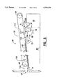
- FIG. 1 is an isometric view of an automated banking machine.
- FIG. 2 is an isometric view of the receipt transport and retrieval apparatus of a preferred embodiment of the present invention.
- FIG. 3 is a schematic side view of the apparatus shown in FIG. 2 with the gate member in a first position.
- FIG. 4 is a view similar to FIG. 3 but with the gate member moved to a second position by engagement with a sheet.
- FIG. 5 is a view similar to FIG. 4 but with a sheet positioned at an outlet.
- FIG. 6 is a view similar to FIG. 5 but with a sheet shown in the process of being retrieved.
- FIG. 7 is a view similar to FIG. 6 with the sheet retrieved and held in a storage location.
- FIG. 8 is a schematic view of the apparatus shown in FIG. 2 moved to a service condition to access retrieved sheets in the storage location.
- FIG. 9 is an isometric view of the gate of the apparatus of the invention.
- FIG. 10 is a top plan view of the gate shown in FIG. 9.
- FIG. 11 is a right side view of the gate shown in FIG. 9.
- FIG. 12 is a cross-sectional end view of a frame and belt flights moving a sheet in the apparatus of the present invention.
- FIG. 13 is a schematic representation of steps executed by a controller of the preferred embodiment in a printing and transport control routine.
- FIGS. 14 through 16 are a schematic representation of steps executed by the controller in a paper loading and grading routine.
- FIG. 17 is a schematic representation of steps executed by the controller in a paper form length control routine.
- FIGS. 18 through 20 are a schematic representation of steps executed by the controller in a cut form routine.
- FIG. 21 is a schematic representation of steps executed by the controller in a present form routine.
- FIGS. 22 and 23 are a schematic representation of steps executed by the controller in a retract form routine.
- FIG. 24 is a schematic representation of steps executed by the controller in a purge form routine.
- Automated banking machine 10 is an automated teller machine.
- the present invention may be used in other types of automated banking machines including currency counting units, currency acceptors, scrip terminals, POS terminals and similar type devices.
- Automated banking machine 10 includes a fascia 12 which includes a user interface.
- the fascia includes an opening through which a screen 14 may be viewed.
- a screen is used for providing instructions and delivering messages to the user.
- the fascia also has thereon a keyboard 16 through which the user may enter instructions.
- the fascia also includes openings for other types of devices and mechanisms. In the embodiment shown these include a depository opening 18 into which a user may place deposits. A currency delivery opening 20 is also provided through which currency is delivered to the user. The fascia also includes a card entry slot 22 wherein a user inputs a debit or credit card which is used to initiate operation of the machine. The fascia also includes a receipt delivery opening 24 through which transaction receipts are delivered to the user.
- Apparatus 26 includes a base 28 which is supported in an interior area of machine 10.
- Base 28 supports thereon a sheet source, which in the preferred form of the invention is a transaction receipt printer 30 (see FIG. 3).
- Printer 30 is preferably a conventional type receipt printer which prints receipts on sheets using thermal, dot matrix, ink jet, laser or other printing techniques.
- the printer also preferably is fed from a continuous roll or a fan-fold stack of paper.
- the printer also preferably includes a cut-off device for cutting sheets and separating them after the receipt information has been printed thereon.
- the present invention may be used to produce receipts of uniform length or of varied lengths.
- the preferred embodiment of the present invention is also specifically adapted for use with either pre-printed type form receipts or plain paper-type receipts.
- Apparatus 26 further includes a frame 32.
- Frame 32 is supported and rotatably mounted on a pair of uprights 34 and 36.
- Upright 34 supports a drive which includes a motor 38 which is operable to drive a pulley 40 through a belt 42.
- Pulley 40 in turn is connected to a shaft 44.
- Frame 32 is supported on and rotatably movable about shaft 44.
- a pair of pulleys 46 and 48 are mounted on shaft 44. Pulleys 46 and 48 operate to drive a pair of transversely spaced belts 50 and 52 respectively. Belts 50 and 52 are continuous belts which extend about pulleys 54 and 56. Pulleys 54 and 56 are mounted on a shaft 58 at an opposed end of frame 32 from shaft 44. As best shown in FIG. 12, frame 32 in cross-section includes a lower wall 60. The inside surface of lower wall 60 includes ah upward extending supporting projection 62 thereon. As shown in FIG. 12 a sheet 64 may be transported in engaged relation with lower flights of belts 50 and 52 and supporting projection 62. This arrangement provides for reliable transport of sheets with limited controlled slippage.
- lower wall 60 of transport 32 includes upturned end projections 66 and 68. End projections 66 and 68 include an opening 70 therebetween. Supporting projection 62 extends downward in opening 70.
- Frame 32 further has supported thereon a roller 72 which serves as a supporting member.
- Roller 72 is free-wheeling and is generally engaged with the lower flights of belts 50 and 52.
- Roller 72 further includes a central recess 74 as shown in FIG. 3.
- Supporting projection 62 extends downwardly in recess 74.
- a gate member 76 is rotatably mounted in supported relation on frame 32. Gate member 76 is shown in greater detail in FIGS. 9, 10, and 11. Gate member 76 includes a pair of slots 78 therein. The lower belt flights of belts 50 and 52 each extend in a slot 78 when gate member 76 is in the position shown in FIG. 2.
- a storage location or bin generally indicated 80 is positioned generally below frame 32 in the operative position of the transport and retrieval apparatus shown on FIG. 2.
- Frame 32 is supported in the operative position by member 82, which is attached to base 28.
- member 82 limits the downward rotation of frame 32 about shaft 44.
- An electrical switch is provided to sense when the frame is in the downward position in which the transport is operative to deliver sheets. It should be further noted that member 82 is configured to direct sheets produced by printer 30 toward the lower belt flights and gate member 76.
- Gate member 76 is shown in greater detail in FIGS. 9 through 11.
- Gate member 76 is arcuate in cross-sectional profile and includes an outside surface 86 and an inside surface 88.
- Gate 76 includes spaced end walls 90. End walls 90 have inwardly tapered portions 92.
- End walls 90 further include a pair of outwardly directed shaft projections 94.
- Shaft projections are journaled in supported relation on frame 32 and comprise a pivot. It should be noted that shaft projections 94 are disposed off-center from a center of the arcs of the inside and outside surfaces. The center of the arcs is schematically indicated 95 in FIG. 11.
- End walls 90 each further include outward extending stop projections 96.
- the purpose of stop projections 96 is later discussed in detail.
- Inside surface 88 further includes small inward extending projections 98 thereon.
- Inward extending projections 98 serve to break surface tension between sheets passing in supported relation with the inside surface in a manner later discussed.
- the inward extending projections 98 also keep the leading edges of sheets from catching on the bottoms of slots 78.
- Gate member 76 further includes a top edge 100. Slots 78 extend transversely through the inside and outside surfaces of the gate member and terminate at top edge 100. Top edge 100 is somewhat tapered and thinned relative to the remainder of the arcuate profile of the gate member as shown in FIG. 11. Gate member 76 further includes a bottom edge 102. Inside surface 88 extends in an are approximately 180 degrees between the top edge and the bottom edge. Slots 78 extend in a first portion generally indicated 104 of the outside surface of the gate member. The outside surface also has a second portion generally indicated 106 which is a smooth, arcuate surface and which provides low resistance to the movement of sheets thereon.
- the gate member 76 is biased by gravity to rotate about shaft projections 94 in a clockwise direction from the position shown in FIG. 11.
- This weight distribution provide a biasing means which is operative to move the gate member in a manner later discussed.
- Printer 30 delivers a sheet 108 which in the preferred embodiment comprises a transaction receipt form.
- Printer 30 delivers the sheet 108 upwardly toward the lower belt flights of belts 50 and 52. Only belt 52 is shown in the Figures for purposes of simplicity.
- First sensor 110 is preferably a photoelectric optical type sensor.
- First sensor 110 is operatively connected to a controller 112 which is shown schematically in FIG. 5. The operation of the controller is later discussed in greater detail with reference to FIGS. 13 through 24.
- controller 112 operates the drive by starting motor 38 to begin moving the lower belt flight in an outward direction generally indicated by Arrow A.
- the controller circuit is connected to a control device for the printer so that the drive begins moving responsive to operation of the printer having moved the paper an amount sufficient so that the paper sheet protrudes from the printer sufficiently to engage the belt flights.
- the drive may begin moving responsive to the sensor sensing the sheet moving adjacent thereto.
- Sheet 108 is directed into a delivery area which includes a nip generally indicated 114 formed by the outside surface of the gate member and a downward facing first side of the lower belt flight.
- the delivery area is an area from which the form sheet delivered from the printer may be removed.
- the moving lower belt flight pulls sheet 108 into the nip and causes the sheet to engage the area on the outside surface of the gate member where the belt flight extends through the slot 78.
- a stop serves to prevent rotation of gate member 76 in a clockwise direction.
- the stop operates by engagement of the stop projection 96 on the gate member with a surface of the frame. The stop assures that when the gate member is not being acted upon by a sheet moving in the outward direction, the gate member is maintained in the first position shown in FIG. 3.
- the gate member is preferably freely rotatably movable.
- Shaft projections 94 extend in journaled relation in frame 32. The force applied by sheet 108 moves the gate member to the second position without significant resistance. In the second position of the gate member, sheet 108 is enabled to readily pass in an outward direction over the outside surface of the gate.
- a gap 116 extends between the top edge 100 of the gate member and the roller 72. This gap is substantially closed as the gate member moves from the first position to the second position. This closure of gap 116 operates to insure that sheets passing over the gate member are directed to maintain engagement with the lower belt flight.
- the rotation of roller 72 is in a counter-clockwise direction as shown when the belt flight moves in an outward direction. As a result, any sheets which tend to maintain engagement with the outside surface of the gate member are directed against the moving surface of roller 72 and are directed back into engagement with the belt flight.
- stop further limits movement of gate member 76 in the counter-clockwise direction. This is done by engaging the stop projection 96 with a further surface of the frame as indicated in FIG. 4. Thus the stop prevents the gate member from rotating too far in response to a force applied by the sheet.
- Sheets moving in the outward direction pass the gate member 76. Once the sheets are no longer engaged with the gate member, the gate member returns to the first position due to the biasing force of gravity as represented in FIG. 5.
- the sheets pass in the outward direction along a path which is preferably longer than a sheet length, until they reach an outlet generally indicated 118. At outlet 118 the sheet is accessible to the user.
- sheet 108 extends outwardly at the outlet through the receipt delivery opening 24 in fascia 12.
- the drive operates responsive to the controller to move the lower belt with the engaged sheet in the outward direction until a second photoelectric sensor 120 at the exit end of the path senses the passage of the inward end of the sheet.
- Sensor 120 is connected to controller 112 which operates to stop motor 38, which stops the drive moving the lower belt flight.
- controller runs the transport in reverse until it again senses the inward end of the sheet, and then stops transport movement.
- the sheet 108 remains engaged to the belt flight and is directed slightly upward by the end projections 66 and 68, so as to facilitate its removal by the user through the opening 24.
- the belt flights allow limited slippage so the user may manually remove the extending sheet without damage.
- Controller 112 is operatively connected with a timer schematically indicated 122.
- Controller 112 preferably includes one or more processors, and timer 112 is part of a programmed routine executed by a processor as later discussed. Alternatively, the timer may be resident in another system connected to the controller.
- the controller operates a retract routine to move the drive in an opposed direction such that the lower belt flight moves in an inward direction as indicated by arrow B in FIG. 6. If the customer has not removed the sheet, the controller operates the drive so as to retrieve the sheet in a manner hereinafter described. If, however, the user has removed the sheet 108, the sheet will not be sensed and the controller executes programmed steps in response to this condition. Subsequently the apparatus is ready to deliver the next sheet.
- controller 112 operates the drive so that the lower belt flight moves in the inward direction.
- sheet 108 moves in an inward direction along the path until it engages the arcuate inside surface of gate member 76.
- the sheet is directed in supported relation thereon into the storage location 80. As shown in FIG. 6 as the sheet 108 passes over the inside surface of the gate member it its turned 180 degrees. The sheet is also sensed by sensor 110 as it moves adjacent to the gate member 76.
- the controller 112 runs the drive with the lower belt flight moving in the inward direction for a sufficiently long time and in a manner to assure that the sheet is moved into the storage location. Upon the sheet reaching the storage location it preferably lies in a flat position supported on base 24. Because the retrieved sheet is delivered in a flat orientation, a large number of sheets may be stored in the storage location 80 before the retrieved sheets must be removed. As shown in FIG. 7 once the retrieved sheet has been delivered to the storage location, the transport and retrieval apparatus 26 is ready to deliver and retrieve further sheets from printer 30.
- FIG. 8 The removal of accumulated sheets is schematically demonstrated in FIG. 8.
- a stack 124 of retrieved sheets is housed in storage location 80.
- the controller is operative to detect when the storage location is full in a manner later discussed.
- the stack may be manually accessed and removed by rotating frame 32 about shaft 44 to the position shown in FIG. 8. This transversely disposes the frame and the bell flights supported thereon away from the storage location. In this position the stack 124 is more readily accessed for removal.
- the printer 30 is also readily accessed for purposes of maintenance such as the changing of print cartridges or the replenishment of paper supplies or servicing.
- the frame 132 is returned to the operative position with the belt again extending between the sheet source which is printer 30, and the outlet.
- the retrieved sheets of the embodiment shown lie in a generally horizontal orientation in the storage location 80. This is because the inside surface 88 of the gate member 76 extends generally about 180 degrees. However, in other embodiments of the invention the gate member can have different inside surface contours and angular configurations. For example, a 90 degrees arc may be used to align sheets vertically in a storage location. This may be desirable if storage location space is available only below the gate.
- the system of the preferred embodiment is operated by controller 112 in a number of different ways in response to the occurrence of certain programmed conditions.
- the controller operates to purge forms out of the receipt opening in response to the storage location 80 being fall, or in response to the receipt being too long to retract.
- the controller also operates in ways which are operative to correct malfunctions such as paper jams.
- the controller 112 preferably includes a microprocessor.
- the microprocessor is in operative connection with a memory.
- the memory is preferably a semi-conductor memory or firmware. However, in other embodiments other types of memories may be used.
- the controller which operates the receipt transport and retrieval system of the present invention may also operate the printer 30 and control the printing of the receipt forms. In other embodiments of the invention separate controllers for the printer and the receipt transport and retrieval system may be used.
- FIG. 13 is a schematic representation of the steps executed by the controller in a printing and transport control routine.
- the routine commences from a step 126 in which the printer is operating to print characters or other indicia on the paper.
- the determination is made by the controller 112 as to whether the paper on which printing is being conducted was sensed as having moved in response to the printer efforts to move the paper. Paper movement is preferably sensed using the system shown in co-pending application U.S. Ser. No. 08/568,887 filed Dec. 7, 1995 the disclosure of which is incorporated herein by reference. If it is sensed that the paper is not moving in response to the printer, a fault indication is given by the controller at a step 130.
- the controller next determines at a step 132 if it has received a form feed command. If not, the controller next checks at a step 134 to determine if it has received a cut command which is indicative of an instruction to the printer to cut the paper. If no cut command has been received, a check is made at a step 136 to determine if a present form command has been received. If no command to present a form has been received, a determination is made at a step 138 if a command to retract the form has been received. Finally, a check is made at a step 140 to determine if a purge command has been received.
- step 142 the controller is operative at a step 142 to enable the transport to operate at medium speed.
- the transport is operated in accordance with the particular steps associated with the command that it has received which are hereinafter discussed. From step 142 the controller returns to step 126.
- step 144 a decision is made at a step 144 as to whether the length of paper that the printer has operated to print upon in the current form sufficiently protrudes from the printer to engage the belt flights of the transport. This is preferably done by the controller comparing a distance that the paper has been moved since the last cutting operation to a stored value. If the paper is not yet sufficiently long to engage the belt flights the transport is temporarily disabled at a step 146 and the program steps return to step 126. Once the paper has reached a sufficient length to engage the belt flights the controller executes a step 148. Step 148 is operative to begin moving the belts of the transport in a forward direction at a slow speed.
- the belt flights urge the sheet to move towards the receipt opening 24.
- the configuration of the transport is such that the belts are enabled to overrun in engagement with the receipt form. From step 148 the belts continue to run at low speed until one of the other commands is received.
- FIGS. 14 through 17 schematically demonstrate the steps executed by the controller as part of the paper loading and grading routine.
- the preferred form of the invention is operative to sense characteristics of the paper so that the controller may dynamically store and change stored threshold values to match the character of the paper in the sheets being used.
- the preferred form of the invention is dynamically adaptable to paper of varying quality and color.
- the controller is also preferably operable to store and update threshold values that are indicative of paper being sensed adjacent to a sensor as printing activities are conducted. In this way the preferred form of the system is enabled to operate properly with paper types that vary substantially. It also accommodates variations in the paper which occur in the middle of a roll or fanfold stack.
- the system also dynamically adjusts to the optical properties of "top of form” (TOF) marks when TOF type paper is used.
- TOF top of form
- the paper loading and grading routine commences with an entry step 150 after which a check is made at a step 152 as to whether the transport for the receipts is in the operative position. If the transport has been moved to the position for servicing, such as for changing, the paper supply, the controller will next execute a step 154.
- step 154 the controller is operative to adjust a base paper color value to conform with that presented at a sensor 155 (see FIG. 7).
- Sensor 155 is preferably positioned within a paper path indicated 151 within the printer 30.
- the sensor 155 is positioned in the paper path at a location in advance of at least one paper drive mechanism schematically indicated by rolls 157, 159 which engage the paper and move it in the paper path.
- the sensor 155 is also preferably positioned in the paper path in advance of a paper cutter mechanism, schematically indicated 153.
- Cutter 153 is selectively operative to transversely cut the paper in the paper path.
- Sensor 155 is positioned sufficiently inward in the paper path so that when the end of the paper is sensed at the location by the sensor, the remaining paper can be moved outward by rolls 157 to engage the belts of the transport at the nip 114.
- the senor 155 is an optical type sensor that includes an emitter and a receiver.
- the controller is operative to adjust the intensity of the emitter so that the level of light reflected from the paper and sensed by the receiver in sensor 155 is increased to above a desired level. This assures that sensor 155 may reliably sense the paper adjacent thereto.
- a stored threshold level of the signal from the receiver may be appropriately adjusted to indicate the presence of paper, or both emitter and receiver threshold levels may be adjusted in response to characteristics of the paper. This is preferably accomplished based on reflectance from at least two spaced areas on a sheet, which are then used to set the threshold.
- the readings from the two spaced locations may be averaged, and then an offset taken from the average for purposes of establishing the threshold level.
- the signals from sensor 155 may also be used to change emitter values or to adjust the paper sensing thresholds for signals from sensors 110 and 120.
- TOF marks are dark marks which are positioned on each sheet form. They are used to provide a reference for the printing and cutting of the form. Because TOF marks are uniformly positioned and are much darker (less reflective) than the surrounding surface of the form, the controller may be programmed to respond to the significant reflectance fluctuations, associated with TOF marks and make the decision in step 156 based on the presence or absence of such fluctuations.
- step 158 the printer is operative to advance the paper using rolls 157 and/or other drive mechanisms a sufficient distance to collect sample information concerning both the reflectance of the paper in the area of the TOF marks as well as in areas disposed from the marks.
- the paper is advanced by the printer a distance of at least two TOF marks and threshold values corresponding to the presence of paper and the presence of a TOF mark on the paper adjacent to sensor 155 are updated and stored in memory.
- the controller executes a cut form routine at a step 160 which is later described in detail, and proceeds to the steps that are later discussed in connection with FIG. 16.
- step 156 If it is determined at step 156 that the paper that is being used is not TOF paper, the controller next executes a step 162.
- step 162 the paper is advanced a sufficient distance to insure that the printer is enabled to move the paper reliably. In the preferred form of the invention the paper is moved forward about 10 inches. Thereafter the controller proceeds to step 160 and cuts the paper using cutter mechanism 153.
- Step 164 is a retract routine which is later discussed in connection with FIGS. 22 and 23.
- the controller is operative to move the belts of the transport to assure that any form therein is retracted and moved into the storage location 80. This step assures that before new paper is loaded the transport is clear.
- the controller next executes a step 166.
- the paper is moved forward in the paper path 151 by the drive mechanism in the printer.
- a timing step 168 it is checked to see if an elapsed time has expired without the paper being sensed. If the paper has been attempted to be moved forward beyond the elapsed time without being sensed, the controller executes a step 170 in which the controller sets a status indicating that the printer is out of paper or is experiencing a similar fault. From step 170 the controller exits the routine.
- Step 172 is similar to step 154 previously discussed.
- the controller is operative to evaluate the signals received from sensor 110 and to adjust the threshold intensity of the emitter associated with the sensor, or the threshold levels for signals from the sensor receiver to correspond with the reflectance characteristics of the paper which has been loaded.
- the controller then moves on to a step 174 which is similar to step 156 wherein a determination is made as to whether or not the paper that has been loaded is top of form paper. As with the previously discussed step this may be done based on an input or may be determined based on variations in paper reflectance.
- the controller executes a step 176 in which it sets threshold levels for detection of a TOF mark on the paper. These TOF mark threshold levels are set based on the general reflectance of the paper which is determined at step 172, if the decision as to the presence of TOF paper is based on a manual input. If the determination is made automatically, the mark threshold levels may be based on the reflectance characteristics of the TOF mark(s) sensed in the determination process.
- the controller next executes a step 178 in which a determination is made whether the paper is adjacent to sensor 155. If paper is not sensed adjacent to the entry sensor a determination is made at a step 180 as to whether the paper is sensed adjacent to the exit sensor of the transport which is second sensor 120. If paper is sensed adjacent to the exit sensor but not sensor 155 then there is a problem and a faulty entry sensor status is set at a step 182.
- step 182 the controller is operative to execute a cut paper routine at a step 184 and execute a purge form routine at a step 186. These routines are later discussed in detail. Thereafter the controller proceeds to execute the steps shown in FIG. 16.
- Step 188 is again a determination as to whether or not top of form paper is in use. This determination may be based on an input from a user, based on a determination from variations in reflectance values from the paper, or based on the decision that was made in step 174.
- step 190 the printer is operative to move the paper so as to place a TOF mark adjacent to sensor 155.
- the controller is thereafter operative to adjust the threshold representative of the presence of a TOF mark. This may be done by either adjusting the threshold intensity of an emitter associated with the sensor or adjusting the threshold signal values corresponding to the adjacent TOF mark.
- the: controller After adjusting the thresholds associated with the adjacent TOF mark in step 190, the: controller then executes the cut paper routine at a step 192. After cutting the paper the controller executes the retract routine at a step 194 and advances the paper to position the next TOF mark adjacent to sensor 155 at a step 156.
- step 188 if in step 188 it is determined that top of form paper is not being used, the controller advances to a step 198 in which a cut paper routine is executed. At step 200 the form that has been cut is retracted back into the storage location. At either step 196 or step 200 the controller is operative to execute a step 202 which clears any residual status indication that the reading from the entry sensor is faulty.
- step 204 the controller proceeds to step 204 shown in FIG. 16.
- step 204 the prior values which the controller had been using for sensing TOF marks prior to execution of the current paper loading and grading routine are deleted.
- prior fault values such as a fault value indicative of a paper out condition which existed prior to the current paper loading routine are cleared.
- the controller executes a preprogrammed routine in which it prints a test pattern on a single form, advances the form appropriately based on whether the form is a TOF form sheet or plain paper sheet and executes a cut routine and a retract routine to place the form in the storage location.
- test routine at step 208 executes successfully, information indicative thereof is indicated in the program parameters of the controller at a step 210.
- information indicative thereof is indicated in the program parameters of the controller at a step 210.
- the apparatus has been determined to be out of paper at step 206, status information indicative thereof is updated at step 210.
- the controller exits the program at a step 212.
- the printer responds to electrical signals from the controller which art indicative of the indicia to be printed on the form that is to be delivered.
- the controller executes a step 144 which enables the transport to begin moving at a step 148.
- the form extends in the transport past the gate member,
- the form may be a variable length which is determined by the amount of printing thereon.
- the form may be one or more connected TOF sheets extending in the transport.
- controller When the printing on the form is complete the controller is operative to execute the steps in the cut form routine represented in FIGS. 18 through 20. Thereafter the controller is operative to execute the steps in the present form routine shown in FIG. 21, which operates to present the form sheet to the customer.
- the controller enters the cut form routine at a step 214.
- a determination is made at a step 216 if entry into the routine is erroneous because the form length based on the amount of printing is zero. If the form length is zero, the controller immediately exits the routine at a step 218. Assuming that the form length is not zero as determined at step 216, a determination is then made at a step 220 concerning whether the printed form length is above the minimum necessary for transport. Again this decision is based on the distance the printer has moved the form and conducted printing. If the decision made in the step 220 is that the form length is below the minimum, a step 222 is executed to advance the paper to the minimum form length.
- step 224 which involves making a determination of whether the transport is clear. If in step 224 the exit sensor 120 is sensing a form, a purge routine is executed at a step 226. The purge routine will generally remove the form at the exit and clear the transport. If however at a step 228 it is determined that the exit sensor is still not clear, a problem status is indicated at a step 230 and the controller exits the routine at a step 232.
- step 224 If at step 224 no form is detected near the exit sensor or if the purge routine executed at step 226 is effective to clear the form, the controller executes a step 234.
- step 234 the printer cuts the paper by actuating cutter mechanism 153.
- the controller is also operative to update the top of form and paper reflectance threshold values stored in memory based on the reflectance characteristics of the particular form that has just been processed. This provides for updating the threshold values for each sheet and compensates for variations which occur among the sheets.
- step 234 the controller next proceeds to a step 236 at which a determination is made as to whether the transport is in the operative position. If so, the controller executes step 238 in which the transport moves forward so as to move a form of the minimum transportable length outward into the vicinity of the exit sensor 120. Alternatively, if the transport is found not be in operative position at step 236, the steps shown schematically in FIG. 20 are executed as later discussed.
- step 240 a determination is made as to whether the paper is still being sensed adjacent to the entry sensor 110 in spite of the fact that the form should have been moved a distance sufficient to place it adjacent to the exit sensor. If the form is still adjacent to the entry sensor, a step 242 is executed in which the printer attempts to again cut the paper. From step 242 the transport again at tempts to move the form towards the exit sensor in step 244. This time the advance of the form is attempted at middle speed.
- step 246 a determination is again made as to whether the form is still adjacent to the entry sensor 110. If so, the controller executes a step 248 which indicates a failure status and exits the program at a step 250.
- step 252 which clears any cutter failure status indication which may be in memory.
- the controller then operates the transport to advance the form towards the exit at high speed in step 254.
- step 256 a determination is made as to whether the form is esensed adjacent the exit sensor 120. If so, the steps shown in FIG. 20 are executed.
- step 258 is executed.
- the controller operates the transport so as to advance the form at high speed towards the exit.
- a determination is then made at a step 260 as to whether the form has reached the exit. If the form is now adjacent to the exit sensor the controller proceeds to the steps in FIG. 20. If however the form is not adjacent to the exit sensor the controller proceeds to a step 262.
- a jam-clear routine is executed.
- the controller is operative to move the belts 42 and 52 of the transport in a back and forth motion, first in one direction and then the other.
- the belts move in a first direction and then in an opposed direction from the initial starting point. This is done three times with the displacement of the belts in each direction increasing with each cycle.
- the back and forth movement of the belts in the jam recovery routine is generally operative to clear any jam and enable a stack sheet to begin moving.
- the jam recovery routine is used in a number of situations by the preferred embodiment of the invention.
- step 264 a determination is made as to whether the form was seen during the jam recovery routine adjacent to the exit sensor 120. If so, then the form has been freed and has likely been moved either out of the transport or into the storage location.
- step 266 is executed in which any failure status indications are cleared and the controller proceeds to the steps in FIG. 20.
- step 262 If however the jam recovery routine in step 262 was not sufficient to cause the form to be sensed by the exit sensor, then the controller is operative at step 268 to indicate a present failure status and the controller exits the program at a step 270.
- step 272 any present failure status indications are cleared.
- step 272 any present failure status indications are cleared.
- the controller then executes step 274 in which the form length and print counters are reset. This enables the controller to begin calculating a form length for the next form to be printed.
- step 276 a check is made as to whether the transport remains attached, and if so the controller moves to a step 278 in which it indicates that a form for a customer is now in escrow in the transport. Of course, if the transport is no longer attached then it is not appropriate to indicate that there is a form in escrow. Thereafter the controller exits the routine at a step 280.
- the controller is operative to execute the present form routine schematically represented in FIG. 21.
- the presentation of printed forms is generally done one at a time.
- the preferred embodiment of the present invention enables the holding of more than one form in escrow in the transport if desired. This may be accomplished through appropriate programming which verifies a form as cut by moving it adjacent to the exit sensor 120 and then retracting it based on its length to an intermediate point in the transport pending the printing of additional forms.
- the controller executes the steps schematically indicated in FIG. 21.
- the controller begins by executing a step 282. From there a determination is made at a step 284 as to whether the transport is properly attached. If the transport is not attached a determination is made at a step 286 as to whether a form has been printed on or advanced. If not, the controller sets a form taken status at a step 288 and exits the program at a step 290. Likewise, if a form has been printed upon the controller executes a step 292 to feed the form. From step 292 the controller then proceeds through steps 288 and 290 to exit the program.
- step 284 If in step 284 it is determined that the transport is attached the controller proceeds to a step 294.
- step 294 a determination is made as to whether there is a status indicated in memory which represents that there is a form in escrow in the transport. If not, the controller exits the program. If however the proper status of a form being in escrow is indicated, the controller executes a step 296. In step 296 the controller operates the transport in an effort to move the form outward beyond the exit sensor 120.
- step 296 While moving the form outward in step 296 an elapsed time is measured in a step 298. If the form is not sensed as having moved outward past the exit sensor within the elapsed time, then the jam recovery routine is executed at a step 300.
- the jam recovery routine is similar to that previously discussed in which the belts move cyclically back and forth in an effort to move the form.
- step 306 the controller is operative to execute a step 308.
- step 308 the controller monitors whether the form has been taken by the customer. If the customer takes the form the form will be no longer detected by the exit sensor. Also during step 308 the controller is operative to execute a timing routine. As previously discussed, if the form is present at the exit sensor longer than a time set in the programming of the controller, the form will be retracted in accordance with the steps described in connection with FIGS. 22 and 23. When the form is presented in monitoring step 308 the controller exits the routine through a step 310.
- step 308 the customer takes the form, then a form taken status is indicated and the transport is ready to proceed to present the next form to either the same customer or a different customer. If however the customer fails to take the form within the time specified the controller is operative to execute the steps represented by the retract routine graphically represented in FIGS. 22 and 23.
- the controller enters the retract form routine beginning with a step 312. From step 312 a determination is made at a step 314 as to whether the transport is attached. If not, the controller exits the program at a step 316. If the transport is attached, the controller executes a step 318 in which a determination is made as to whether a status is indicated as the transport having a form in escrow. If at step 318 it is determined that the status indicative of a form being in escrow in the transport is no longer in memory, the controller operates to execute a step 320 in which the transport is run in reverse for sufficient time to retract any form that may be in the transport into the storage location, and then exits the routine.
- step 318 the controller determines that there is a status indication that a form is in escrow in the transport, the controller moves to a step 322.
- step 322 a determination is made concerning the length of the form that the printer has printed based on the line counters in the printer. The determination made in step 322 is whether the form is longer than the maximum length which can be retracted by the transport. It should be understood that in the preferred embodiment of the invention the printer is enabled to print forms which extend from the printer all the way through the transport to the customer. Therefore it is possible to have a form which is longer than can be retracted.
- step 324 is executed by the controller.
- step 324 the steps in the purge routine shown in FIG. 24 are carried out.
- the controller is operative to execute a step 326 in which the form status is indicated as taken, and the controller exits the routine at a step 328.
- step 322 If in step 322 it is determined based on the length of form printed that the form in escrow is not too long to be retracted, the controller proceeds to a step 330.
- step 330 a determination is made as to whether the form is currently adjacent to the exit sensor 120. IF so, the controller executes a step 332 in which the transport is run in reverse to clear the exit sensor. After executing step 332, a step 334 is executed to determine if the form is still adjacent the exit. If so, the controller executes a purge form routine at a step 336. Thereafter the controller is operative to execute a jam recovery routine at a step 338. The controller then executes a step 340 to indicate that the form has been taken and exits the program at a step 342.
- step 344 the controller is operative to run the transport in reverse until the form is sensed adjacent to the transport entry sensor 110. As shown in FIG. 23, a determination is made at a step 346 as to whether the form has moved adjacent to the entry sensor. If not, the controller is operative to operate a jam recovery routine at a step 348.
- step 350 the transport is continued to be run in a reverse direction until the entry sensor is clear. This indicates that the form has been retracted and directed by the gate member into the storage location 80.
- the controller next executes a step 352 in which a determination is made as to whether despite the operation of step 350 the form is still sensed adjacent to the entry sensor. If so, this is indicative that the storage location is full. An indication thereof is given by the controller through the execution of a step 354, and thereafter the controller exits the routine at a step 356.
- step 352 If in step 352 the form is no longer sensed adjacent to the entry sensor this indicates that it has been likely properly retracted into the storage location.
- the controller next executes a step 358.
- step 358 the controller is operative to run the transport forward a short distance and then stop.
- a step 360 is then executed in which a determination is made as to whether running the transport forward this short distance has pulled a form from the storage location which is sensed by the entry sensor. If so, this is indicative that the storage location is full and step 354 is executed.
- step 360 If however in step 360 it is determined that the storage location is not full, a step 362 is executed. In step 362 the controller is operative to run the transport in reverse a distance similar to the distance that the transport was run forward in step 358.
- step 364 a determination is made as to whether the form was seen by the entry sensor 110 during the course of conducting the retract routine. If so, a step 366 is executed in which a form retracted status is set by the controller. If however in step 364 it is determined that the form was not sensed by the entry sensor, then this is indicative that the customer took the form or that it was otherwise moved out of the transport. In response to this condition the controller is operative to execute a step 368 and to set a form taken status. From either steps 368 or 366 the controller exits the routine at a step 370.
- the purge routine referred to in the discussion of the prior program steps is schematically represented in FIG. 24.
- the controller enters the routine through a step 372 and thereafter makes a determination in a step 374 as to whether the transport is attached to the printer. If the transport is not attached, the controller exits the routine in a step 376.
- the controller next executes a step 378 in which a determination is made as to whether the printer has printed a form or a form has been advanced. If not, a form is advanced at a step 380.
- the controller is then operative at a step 382 to run the belts of the transport in a forward direction a distance sufficient to push any forms in the transport outward through the receipt opening 24. In the preferred form of the invention the distance that the belts are moved forward is about 20 inches.
- step 382 the controller next executes a step 384 in which a determination is made as to whether either of sensors 110 or 120 detect a form adjacent thereto. If so, a jam recovery routine is conducted at a step 386.
- the jam recovery routine is similar to that previously discussed in which the belts undergo an oscillating motion in an effort to clear a stuck form.
- a determination is made at a step 388 as to whether a form is sensed adjacent to either of the sensors of the transport. If not, or alternatively if the transport sensors were clear at step 384, the controller is operative at a step 390 to set a form purged status indicative that the form has been pushed out of the receipt opening and that the transport is clear.
- the controller is thereafter operative to exit the program at a step 392. If however at step 388 it is determined that a form is still sensed adjacent to one of the transport sensors, then the controller is operative at a step 394 to set a purge fail status. The controller then exits the routine.
- a further novel feature of the preferred embodiment of the present invention is that it avoids cutting of the paper when approaching the end of the paper supply. This is particularly helpful when a continuous roll of paper is used as the supply and the cutting of the paper after printing the "last" form will leave a short scrap of paper which cannot be handled by the printer or transport. Such a scrap piece of paper may jam the printer when new paper is fed.
- a form length control routine which is executed by the controller is schematically represented by the steps shown in FIG. 17.
- the form length control is operative in the processing of each form.
- This routine is critically involved when little paper is left and it is desired to install a new roll or supply. Alteratively, the routine may be used to test paper movement.
- the controller proceeds to determine if the system is in a transactional mode or a service mode at a step 397. The setting of this mode is based on inputs or other conditions sensed by the controller. If the system is in service mode, the controller proceeds to determine if a feed switch is enabled at a step 398.
- the feed switch is a manual type switch that is enabled by the controller. For example, the controller may disable the feed switch in response to certain status conditions. If the feed switch is determined not to be enabled in step 398 the controller exits the routine at a step 400.
- step 400 the controller next executes a step 402 to determine if the feed switch has been manually pressed. This is done when test feeding paper or when unloading paper from an almost depleted supply so a new supply may be installed. If the switch has not been pressed the controller exits the routine at a step 404. If the feed switch was pressed the controller moves on to a step 406.
- step 406 which is reached from either step 397 or step 402 a determination is made as to whether the paper being used is TOF paper. As previously discussed, this can the based on an input by a user indicative that TOF paper is being used. Alternatively, this may be derived by moving the paper past the sensor 155 and sensing the periodic variations in reflectance associated with the presence of TOF marks.
- TOF paper is indicated at step 406 the paper is advanced at a step 408 to the next TOF mark or until the amount the paper advanced corresponds to a programmed maximum form length. However, if TOF paper is not indicated in step 406, the non-TOF paper is advanced in a step 410 an amount which corresponds to the minimum form length suitable for handling by the transport.
- step 416 a determination is made as to whether paper is still being supplied. This determination is preferably made based on sensor 155 no longer sensing paper. Alternatively, the end of the paper may be sensed using the apparatus disclosed in U.S. patent application Ser. No. 08/568,887 the disclosure of which is incorporated herein by reference. If paper is no longer being supplied, the cutting action of the cutter mechanism 153 associated with the printer 30 is disabled at a step 417.
- step 418 the controller proceeds to execute the cut routine in step 418.
- step 417 was executed the paper is not actually cut during the cut routine. As a result all the paper remaining in the supply is moved through the printer and into the transport. In other cases the length of form pulled into the transport in step 418 will be the minimum form length or the maximum retractable form length.
- the controller determines if it is in transactional mode or service mode at a step 419. If the machine is in service mode the controller executes a retract routine at a step 420. The retract routine is operative to retract the form into the storage location. If at step 419 the controller is in the transactional mode, the controller executes a present form routine at a step 421. The execution of this routine will generally result in delivery of the form to a customer. At a next step 422 the controller operates to update its internal status record. If for example, the paper is now out, a status indicative thereof is set. Likewise if a form was cut as a test, the status set indicates that the paper is loaded and the transport is ready. The controller then exits the routine at a step 426.
- the paper cutting and printing activities are suspended whenever the paper is sensed as depleted.
- the remaining paper is sufficiently long to be moved by the printer transport mechanism through rolls 157, into engagement with the belts of the transport.
- the transport carries the last portion of the paper away from the printer.
- the sensor 155 is enabled to provide a signal to the controller which indicates that it should cease further operation of the cutter. In this embodiment this result is achieved because the location in the paper path at which sensor 155 senses the paper is disposed a first distance in the paper path from the final drive rolls 157 which engage and move paper through the printer. This first distance is greater than a second distance that the paper must extend beyond the drive rolls 157 in the paper path to reach the delivery area from which the form sheets may be taken.
- the delivery area includes the nip 114 from which the transport may take the sheets. Of course, in other embodiments the delivery area may be an entrance to a different type of transport or an area in which a sheet may be manually engaged by a customer.
- the cutter mechanism 153 is disposed in the paper path upstream from the rolls 157, so the rolls may solidly move the cut sheets to the delivery area.
- the cutter may be positioned on the downstream side of the final drive rolls 157.
- the place where indicia are printed on the paper by the printer mechanism is positioned upstream in the paper path from both the cutter and the final drive rolls.
- different arrangements may be used in other embodiments.
- sensor 155 is used to sense the presence of paper at a single location in the paper path, and the controller discontinues cutting operations as soon as the sensor no longer senses the paper
- other embodiments may use other types of sensors and may delay the cessation of cutting activities until the paper has moved a further distance beyond the condition where the end of the paper supply is sensed. This will depend on the system configuration, the ability to calculate the distance the paper moves and the amount of paper remaining when the end of the paper is sensed.
- Those skilled in the art will devise other embodiments of the invention which employ the fundamental aspects of avoiding production of a form sheet which is too short to extend from the drive to the delivery area based on the disclosure herein.
- the system includes an auto load feature.
- the servicer extends paper from a new roll or other supply into the printer.
- the paper is sensed by a paper sensor within the printer positioned upstream of the drive rolls.
- the printer is operated to engage the paper and move it to a position in which it is ready for printing. As a result the time required to install a new paper supply is greatly reduced.
- controller 112 is described as adjusting threshold levels for detection of paper at the entry sensor 155, corresponding threshold levels for detecting paper at the transport sensors 110 and 120 may similarly be adjusted. This may be done either through the process of sensing successive areas on a sheet with sensor 110 or 120 in a manner similar to that described with reference to sensor 155, or by adjusting threshold levels for one or both sensors 110 and 120 in accordance with the paper characteristics as determined using sensor 155.
- the preferred form of the present invention provides a simple yet highly reliable transport and retrieval apparatus for receipts and other sheets delivered by an automated banking machine.
- the invention is also highly compact because of the gate member and the ability of the apparatus to store numerous retrieved sheets in a stacked relation in a confined area. It also enables ready removal of the retrieved sheets as well as superior access for servicing the components thereof. It is also self-adapting to various form and paper types.
- the new sheet transport and retrieval system of the present invention achieves the above-stated objectives, eliminates difficulties encountered in the use of prior devices and systems, solves problems and attains the desirable results described herein.
- any feature described as a means for performing a function shall be construed as encompassing any means capable of performing the recited function, and shall not be deemed limited to the means shown or described herein for performing the recited function or mere equivalents thereof.
Abstract
Description
Claims (19)
Priority Applications (7)
| Application Number | Priority Date | Filing Date | Title |
|---|---|---|---|
| US08/827,567 US5779379A (en) | 1997-03-28 | 1997-03-28 | Receipt form handling system for automated banking machine |
| EP97950895A EP0971820B1 (en) | 1996-11-27 | 1997-11-25 | automated banking machine |
| BR9714889-0A BR9714889A (en) | 1996-11-27 | 1997-11-25 | "system for issuing receipt forms in an automatic bank machine" |
| PCT/US1997/022511 WO1998023448A1 (en) | 1996-11-27 | 1997-11-25 | Receipt form handling system for automated banking machine |
| CA002271050A CA2271050C (en) | 1996-11-27 | 1997-11-25 | Receipt form handling system for automated banking machine |
| DE69730998T DE69730998T2 (en) | 1996-11-27 | 1997-11-25 | MONEY MACHINE |
| ES97950895T ES2229396T3 (en) | 1996-11-27 | 1997-11-25 | AUTOMATIC BANK CASHIER. |
Applications Claiming Priority (1)
| Application Number | Priority Date | Filing Date | Title |
|---|---|---|---|
| US08/827,567 US5779379A (en) | 1997-03-28 | 1997-03-28 | Receipt form handling system for automated banking machine |
Publications (1)
| Publication Number | Publication Date |
|---|---|
| US5779379A true US5779379A (en) | 1998-07-14 |
Family
ID=25249552
Family Applications (1)
| Application Number | Title | Priority Date | Filing Date |
|---|---|---|---|
| US08/827,567 Expired - Lifetime US5779379A (en) | 1996-11-27 | 1997-03-28 | Receipt form handling system for automated banking machine |
Country Status (1)
| Country | Link |
|---|---|
| US (1) | US5779379A (en) |
Cited By (51)
| Publication number | Priority date | Publication date | Assignee | Title |
|---|---|---|---|---|
| US5927879A (en) * | 1997-12-05 | 1999-07-27 | International Business Machines Corporation | Medium processing apparatus and ejected medium drop prevention mechanism |
| US20030069856A1 (en) * | 2001-10-10 | 2003-04-10 | First Data Corporation | Method and system for performing money transfer transactions |
| US6547464B1 (en) * | 1999-12-01 | 2003-04-15 | Diebòld, Incorporated | Automated transaction machine printer |
| US20030126083A1 (en) * | 2002-01-03 | 2003-07-03 | First Data Corporation | Method for receiving electronically transferred funds using an automated teller machine |
| US20040136141A1 (en) * | 2002-12-19 | 2004-07-15 | Avx Corporation | Transmission line capacitor |
| US20050167481A1 (en) * | 1999-10-26 | 2005-08-04 | First Data Corporation | System and method for transferring money from one country to a stored value account in a different country |
| US20060163341A1 (en) * | 1999-10-26 | 2006-07-27 | First Data Corp. | Internet funds transfer system using ATM pickup |
| US7096205B2 (en) | 2001-03-31 | 2006-08-22 | First Data Corporation | Systems and methods for enrolling consumers in goods and services |
| US20060191999A1 (en) * | 1999-10-26 | 2006-08-31 | First Data Corporation | Method and system for performing money transfer transactions |
| US7103577B2 (en) | 2001-03-31 | 2006-09-05 | First Data Corporation | Systems and methods for staging transactions, payments and collections |
| US7117183B2 (en) | 2001-03-31 | 2006-10-03 | First Data Coroporation | Airline ticket payment and reservation system and methods |
| US7130817B2 (en) | 2000-12-15 | 2006-10-31 | First Data Corporation | Electronic gift linking |
| US20060253321A1 (en) * | 2005-05-06 | 2006-11-09 | First Data Corporation | Loyalty enrollment systems and methods |
| US20060253320A1 (en) * | 2005-05-06 | 2006-11-09 | First Data Corporation | Loyalty systems and methods |
| US7158955B2 (en) | 2001-03-31 | 2007-01-02 | First Data Corporation | Electronic identifier payment systems and methods |
| US7184989B2 (en) | 2001-03-31 | 2007-02-27 | First Data Corporation | Staged transactions systems and methods |
| US7219832B2 (en) | 2004-06-17 | 2007-05-22 | First Data Corporation | ATM machine and methods with currency conversion capabilities |
| US7266533B2 (en) | 2000-12-15 | 2007-09-04 | The Western Union Company | Electronic gift greeting |
| US20070258748A1 (en) * | 2004-09-30 | 2007-11-08 | Satoru Moriyama | Printer and Printing Method |
| US20070267480A1 (en) * | 1999-10-26 | 2007-11-22 | The Western Union Company | Value transfer systems and methods |
| US7392940B2 (en) | 2005-05-18 | 2008-07-01 | The Western Union Company | In-lane money transfer systems and methods |
| US7398252B2 (en) | 2000-07-11 | 2008-07-08 | First Data Corporation | Automated group payment |
| US20080247794A1 (en) * | 2004-10-13 | 2008-10-09 | Canon Kabushiki Kaisha | Image forming device, control method of image forming device, program for achieving control method, and storage medium for storing program |
| US7463946B2 (en) | 2001-11-08 | 2008-12-09 | First Data Corporation | Mail handling equipment and methods |
| US7587342B2 (en) | 2000-07-11 | 2009-09-08 | First Data Corporation | Method for requesting and receiving an online payment through a payment enabler system |
| US7596529B2 (en) | 2002-02-13 | 2009-09-29 | First Data Corporation | Buttons for person to person payments |
| US7606734B2 (en) | 2000-07-11 | 2009-10-20 | The Western Union Company | Wide area network person-to-person payment |
| US7613653B2 (en) | 1999-12-30 | 2009-11-03 | First Data Corporation | Money order debit from stored value fund |
| US7641109B2 (en) | 2005-05-18 | 2010-01-05 | The Western Union Company | Money transfer cards, systems and methods |
| US7783571B2 (en) | 2007-05-31 | 2010-08-24 | First Data Corporation | ATM system for receiving cash deposits from non-networked clients |
| US20110069976A1 (en) * | 2009-09-18 | 2011-03-24 | Fuji Xerox Co., Ltd. | Image forming apparatus, recording medium transportation apparatus, recording medium transportation method and computer readable medium |
| US7933835B2 (en) | 2007-01-17 | 2011-04-26 | The Western Union Company | Secure money transfer systems and methods using biometric keys associated therewith |
| US20110293347A1 (en) * | 2010-05-31 | 2011-12-01 | Toshiba Tec Kabushiki Kaisha | Paper discharge apparatus, paper discharge method, image forming apparatus and image forming method |
| US20120010061A1 (en) * | 2010-07-12 | 2012-01-12 | Toshiba Tec Kabushiki Kaisha | Paper discharge apparatus, paper discharge method, image forming apparatus and image forming method |
| US8150763B2 (en) | 2001-03-31 | 2012-04-03 | The Western Union Company | Systems and methods for staging transactions, payments and collections |
| US8244632B2 (en) | 2001-10-26 | 2012-08-14 | First Data Corporation | Automated transfer with stored value |
| US8271382B2 (en) | 1999-10-26 | 2012-09-18 | The Western Union Company | Systems and methods of introducing and receiving information across a computer network |
| US20130014624A1 (en) * | 2011-07-11 | 2013-01-17 | Toshiba Tec Kabushiki Kaisha | Paper discharging apparatus, paper discharging method, image forming apparatus and image forming method |
| US8374962B2 (en) | 2001-10-26 | 2013-02-12 | First Data Corporation | Stored value payouts |
| US20130068834A1 (en) * | 2011-09-15 | 2013-03-21 | Oki Electric Industry Co., Ltd. | Automatic transaction apparatus |
| US8504473B2 (en) | 2007-03-28 | 2013-08-06 | The Western Union Company | Money transfer system and messaging system |
| US8672220B2 (en) | 2005-09-30 | 2014-03-18 | The Western Union Company | Money transfer system and method |
| US8818904B2 (en) | 2007-01-17 | 2014-08-26 | The Western Union Company | Generation systems and methods for transaction identifiers having biometric keys associated therewith |
| CN104239911A (en) * | 2014-09-12 | 2014-12-24 | 湖南长城信息金融设备有限责任公司 | Large-capacity E-bank verification module issuing system for financial self-service system |
| US8960537B2 (en) | 2004-10-19 | 2015-02-24 | The Western Union Company | Money transfer systems and methods |
| EP2529938A3 (en) * | 2011-06-02 | 2016-08-17 | Fujitsu Component Limited | Printer and method of controlling printer |
| JP2016182792A (en) * | 2015-03-26 | 2016-10-20 | ブラザー工業株式会社 | Printer |
| US9853759B1 (en) | 2001-03-31 | 2017-12-26 | First Data Corporation | Staged transaction system for mobile commerce |
| US11176785B1 (en) | 2020-06-15 | 2021-11-16 | Bank Of America Corporation | Detection of dispensing errors in automated teller machines |
| EP4116104A1 (en) * | 2021-07-01 | 2023-01-11 | Toshiba TEC Kabushiki Kaisha | Printer |
| US11643236B2 (en) * | 2017-09-21 | 2023-05-09 | Brother Kogyo Kabushiki Kaisha | Tape and tape cassette |
Citations (8)
| Publication number | Priority date | Publication date | Assignee | Title |
|---|---|---|---|---|
| US4216719A (en) * | 1977-07-13 | 1980-08-12 | Logabox | Printing machine paper drive |
| JPS5919180A (en) * | 1982-07-22 | 1984-01-31 | Fujitsu Ltd | Ticket printing system |
| US4895466A (en) * | 1988-01-20 | 1990-01-23 | Datamax Corporation | Processor for forms with multi-format data |
| EP0459601A2 (en) * | 1990-05-31 | 1991-12-04 | MANNESMANN Aktiengesellschaft | Method and apparatus for positioning continuous forms in printers |
| US5099290A (en) * | 1990-02-15 | 1992-03-24 | Kabushiki Kaisha Sato | Continuous paper printer with monitoring time period in which the paper feed speed is lower than when printing |
| US5452959A (en) * | 1994-08-26 | 1995-09-26 | Ko-Pack Corporation | Apparatus for printing characters onto both surfaces of a sheet material |
| US5588762A (en) * | 1995-02-01 | 1996-12-31 | Star Micronics Co., Ltd. | Paper discharge apparatus |
| US5649776A (en) * | 1994-12-19 | 1997-07-22 | Star Micronics Co., Ltd. | Paper discharge apparatus |
-
1997
- 1997-03-28 US US08/827,567 patent/US5779379A/en not_active Expired - Lifetime
Patent Citations (8)
| Publication number | Priority date | Publication date | Assignee | Title |
|---|---|---|---|---|
| US4216719A (en) * | 1977-07-13 | 1980-08-12 | Logabox | Printing machine paper drive |
| JPS5919180A (en) * | 1982-07-22 | 1984-01-31 | Fujitsu Ltd | Ticket printing system |
| US4895466A (en) * | 1988-01-20 | 1990-01-23 | Datamax Corporation | Processor for forms with multi-format data |
| US5099290A (en) * | 1990-02-15 | 1992-03-24 | Kabushiki Kaisha Sato | Continuous paper printer with monitoring time period in which the paper feed speed is lower than when printing |
| EP0459601A2 (en) * | 1990-05-31 | 1991-12-04 | MANNESMANN Aktiengesellschaft | Method and apparatus for positioning continuous forms in printers |
| US5452959A (en) * | 1994-08-26 | 1995-09-26 | Ko-Pack Corporation | Apparatus for printing characters onto both surfaces of a sheet material |
| US5649776A (en) * | 1994-12-19 | 1997-07-22 | Star Micronics Co., Ltd. | Paper discharge apparatus |
| US5588762A (en) * | 1995-02-01 | 1996-12-31 | Star Micronics Co., Ltd. | Paper discharge apparatus |
Cited By (96)
| Publication number | Priority date | Publication date | Assignee | Title |
|---|---|---|---|---|
| US5927879A (en) * | 1997-12-05 | 1999-07-27 | International Business Machines Corporation | Medium processing apparatus and ejected medium drop prevention mechanism |
| US7613655B2 (en) | 1999-10-26 | 2009-11-03 | Western Union Company | Value transfer systems and methods |
| US20080215487A1 (en) * | 1999-10-26 | 2008-09-04 | The Western Union Company | Method and system for performing money transfer transactions |
| US20070267480A1 (en) * | 1999-10-26 | 2007-11-22 | The Western Union Company | Value transfer systems and methods |
| US8955741B2 (en) | 1999-10-26 | 2015-02-17 | The Western Union Company | Money transfer systems and methods for travelers |
| US8494956B2 (en) | 1999-10-26 | 2013-07-23 | The Western Union Company | Internet funds transfer system using ATM pickup |
| US20050167481A1 (en) * | 1999-10-26 | 2005-08-04 | First Data Corporation | System and method for transferring money from one country to a stored value account in a different country |
| US20060163341A1 (en) * | 1999-10-26 | 2006-07-27 | First Data Corp. | Internet funds transfer system using ATM pickup |
| US8271382B2 (en) | 1999-10-26 | 2012-09-18 | The Western Union Company | Systems and methods of introducing and receiving information across a computer network |
| US20060191999A1 (en) * | 1999-10-26 | 2006-08-31 | First Data Corporation | Method and system for performing money transfer transactions |
| US7549575B2 (en) | 1999-10-26 | 2009-06-23 | The Western Union Company | Money transfer systems and methods for travelers |
| US7950575B2 (en) | 1999-10-26 | 2011-05-31 | The Western Union Company | Method and system for performing money transfer transactions |
| US7673792B2 (en) | 1999-10-26 | 2010-03-09 | The Western Union Company | Method and system for performing money transfer transactions |
| US7578434B2 (en) | 1999-10-26 | 2009-08-25 | The Western Union Company | System and method for transferring money from one country to a stored value account in a different country |
| US20100179908A1 (en) * | 1999-10-26 | 2010-07-15 | The Western Union Company | Method And System For Performing Money Transfer Transactions |
| US7654449B2 (en) | 1999-10-26 | 2010-02-02 | The Western Union Company | Method and system for performing money transfer transactions |
| US10558960B2 (en) | 1999-10-26 | 2020-02-11 | The Western Union Company | Cash payment for remote transactions |
| US6547464B1 (en) * | 1999-12-01 | 2003-04-15 | Diebòld, Incorporated | Automated transaction machine printer |
| US7613653B2 (en) | 1999-12-30 | 2009-11-03 | First Data Corporation | Money order debit from stored value fund |
| US7941342B2 (en) | 2000-07-11 | 2011-05-10 | The Western Union Company | Wide area network person-to-person payment |
| US7930216B2 (en) | 2000-07-11 | 2011-04-19 | The Western Union Company | Method for making an online payment through a payment enabler system |
| US8024229B2 (en) | 2000-07-11 | 2011-09-20 | The Western Union Company | Wide area network person-to-person payment |
| US7610222B2 (en) | 2000-07-11 | 2009-10-27 | First Data Corporation | Method for providing a money transfer service through a payment enabler system |
| US10558957B2 (en) | 2000-07-11 | 2020-02-11 | The Western Union Company | Requestor-based funds transfer system and methods |
| US7606734B2 (en) | 2000-07-11 | 2009-10-20 | The Western Union Company | Wide area network person-to-person payment |
| US7398252B2 (en) | 2000-07-11 | 2008-07-08 | First Data Corporation | Automated group payment |
| US7937292B2 (en) | 2000-07-11 | 2011-05-03 | The Western Union Company | Wide area network person-to-person payment |
| US7587342B2 (en) | 2000-07-11 | 2009-09-08 | First Data Corporation | Method for requesting and receiving an online payment through a payment enabler system |
| US7941346B2 (en) | 2000-07-11 | 2011-05-10 | The Western Union Company | Wide area network person-to-person payment |
| US7908179B2 (en) | 2000-12-15 | 2011-03-15 | The Western Union Company | Electronic gift linking |
| US7512552B2 (en) | 2000-12-15 | 2009-03-31 | The Western Union Company | Electronic gift linking |
| US7130817B2 (en) | 2000-12-15 | 2006-10-31 | First Data Corporation | Electronic gift linking |
| US7266533B2 (en) | 2000-12-15 | 2007-09-04 | The Western Union Company | Electronic gift greeting |
| US8706640B2 (en) | 2001-03-31 | 2014-04-22 | The Western Union Company | Systems and methods for enrolling consumers in goods and services |
| US7103577B2 (en) | 2001-03-31 | 2006-09-05 | First Data Corporation | Systems and methods for staging transactions, payments and collections |
| US8515874B2 (en) | 2001-03-31 | 2013-08-20 | The Western Union Company | Airline ticket payment and reservation system and methods |
| US9129464B2 (en) | 2001-03-31 | 2015-09-08 | The Western Union Company | Staged transactions systems and methods |
| US7096205B2 (en) | 2001-03-31 | 2006-08-22 | First Data Corporation | Systems and methods for enrolling consumers in goods and services |
| US9853759B1 (en) | 2001-03-31 | 2017-12-26 | First Data Corporation | Staged transaction system for mobile commerce |
| US8150763B2 (en) | 2001-03-31 | 2012-04-03 | The Western Union Company | Systems and methods for staging transactions, payments and collections |
| US7158955B2 (en) | 2001-03-31 | 2007-01-02 | First Data Corporation | Electronic identifier payment systems and methods |
| US7107249B2 (en) | 2001-03-31 | 2006-09-12 | First Data Corporation | Electronic identifier payment systems and methods |
| US7184989B2 (en) | 2001-03-31 | 2007-02-27 | First Data Corporation | Staged transactions systems and methods |
| US7716128B2 (en) | 2001-03-31 | 2010-05-11 | The Western Union Company | Electronic indentifier payment systems and methods |
| US7117183B2 (en) | 2001-03-31 | 2006-10-03 | First Data Coroporation | Airline ticket payment and reservation system and methods |
| US7165052B2 (en) | 2001-03-31 | 2007-01-16 | First Data Corporation | Payment service method and system |
| US20030069856A1 (en) * | 2001-10-10 | 2003-04-10 | First Data Corporation | Method and system for performing money transfer transactions |
| US8374962B2 (en) | 2001-10-26 | 2013-02-12 | First Data Corporation | Stored value payouts |
| US8244632B2 (en) | 2001-10-26 | 2012-08-14 | First Data Corporation | Automated transfer with stored value |
| US7463946B2 (en) | 2001-11-08 | 2008-12-09 | First Data Corporation | Mail handling equipment and methods |
| US20030126083A1 (en) * | 2002-01-03 | 2003-07-03 | First Data Corporation | Method for receiving electronically transferred funds using an automated teller machine |
| US7617157B2 (en) | 2002-01-03 | 2009-11-10 | The Western Union Company | Method for receiving electronically transferred funds using an automated teller machine |
| US7596529B2 (en) | 2002-02-13 | 2009-09-29 | First Data Corporation | Buttons for person to person payments |
| US20040136141A1 (en) * | 2002-12-19 | 2004-07-15 | Avx Corporation | Transmission line capacitor |
| US6898070B2 (en) | 2002-12-19 | 2005-05-24 | Avx Corporation | Transmission line capacitor |
| US7458507B2 (en) | 2004-06-17 | 2008-12-02 | First Data Corporation | ATM machine and methods with currency conversion capabilities |
| US7219832B2 (en) | 2004-06-17 | 2007-05-22 | First Data Corporation | ATM machine and methods with currency conversion capabilities |
| US20070228150A1 (en) * | 2004-06-17 | 2007-10-04 | First Data Corporation | Atm machine and methods with currency conversion capabilities |
| US8016501B2 (en) * | 2004-09-30 | 2011-09-13 | Brother Kogyo Kabushiki Kaisha | Printer and printing method |
| US20070258748A1 (en) * | 2004-09-30 | 2007-11-08 | Satoru Moriyama | Printer and Printing Method |
| US20080247794A1 (en) * | 2004-10-13 | 2008-10-09 | Canon Kabushiki Kaisha | Image forming device, control method of image forming device, program for achieving control method, and storage medium for storing program |
| US8960537B2 (en) | 2004-10-19 | 2015-02-24 | The Western Union Company | Money transfer systems and methods |
| US20060253321A1 (en) * | 2005-05-06 | 2006-11-09 | First Data Corporation | Loyalty enrollment systems and methods |
| US20060253320A1 (en) * | 2005-05-06 | 2006-11-09 | First Data Corporation | Loyalty systems and methods |
| US7753267B2 (en) | 2005-05-18 | 2010-07-13 | The Western Union Company | In-lane money transfer systems and methods |
| US9384476B2 (en) | 2005-05-18 | 2016-07-05 | The Western Union Company | Money transfer system and method |
| US7641109B2 (en) | 2005-05-18 | 2010-01-05 | The Western Union Company | Money transfer cards, systems and methods |
| US7392940B2 (en) | 2005-05-18 | 2008-07-01 | The Western Union Company | In-lane money transfer systems and methods |
| US8851371B2 (en) | 2005-05-18 | 2014-10-07 | The Western Union Company | In-lane money transfer systems and methods |
| US8672220B2 (en) | 2005-09-30 | 2014-03-18 | The Western Union Company | Money transfer system and method |
| US8818904B2 (en) | 2007-01-17 | 2014-08-26 | The Western Union Company | Generation systems and methods for transaction identifiers having biometric keys associated therewith |
| US7933835B2 (en) | 2007-01-17 | 2011-04-26 | The Western Union Company | Secure money transfer systems and methods using biometric keys associated therewith |
| US9123044B2 (en) | 2007-01-17 | 2015-09-01 | The Western Union Company | Generation systems and methods for transaction identifiers having biometric keys associated therewith |
| US8504473B2 (en) | 2007-03-28 | 2013-08-06 | The Western Union Company | Money transfer system and messaging system |
| US10311410B2 (en) | 2007-03-28 | 2019-06-04 | The Western Union Company | Money transfer system and messaging system |
| US8762267B2 (en) | 2007-03-28 | 2014-06-24 | The Western Union Company | Money transfer system and messaging system |
| US7783571B2 (en) | 2007-05-31 | 2010-08-24 | First Data Corporation | ATM system for receiving cash deposits from non-networked clients |
| US20110069976A1 (en) * | 2009-09-18 | 2011-03-24 | Fuji Xerox Co., Ltd. | Image forming apparatus, recording medium transportation apparatus, recording medium transportation method and computer readable medium |
| US20110293347A1 (en) * | 2010-05-31 | 2011-12-01 | Toshiba Tec Kabushiki Kaisha | Paper discharge apparatus, paper discharge method, image forming apparatus and image forming method |
| US20120010061A1 (en) * | 2010-07-12 | 2012-01-12 | Toshiba Tec Kabushiki Kaisha | Paper discharge apparatus, paper discharge method, image forming apparatus and image forming method |
| US8721207B2 (en) * | 2010-07-12 | 2014-05-13 | Toshiba Tec Kabushiki Kaisha | Paper discharge apparatus, paper discharge method, image forming apparatus and image forming method |
| EP2529938A3 (en) * | 2011-06-02 | 2016-08-17 | Fujitsu Component Limited | Printer and method of controlling printer |
| US9944485B2 (en) | 2011-07-11 | 2018-04-17 | Toshiba Tec Kabushiki Kaisha | Paper discharging apparatus, paper discharging method, image forming apparatus and image forming method |
| US20150108197A1 (en) * | 2011-07-11 | 2015-04-23 | Toshiba Tec Kabushiki Kaisha | Paper discharging apparatus, paper discharging method, image forming apparatus and image forming method |
| US8925432B2 (en) * | 2011-07-11 | 2015-01-06 | Toshiba Tec Kabushiki Kaisha | Paper discharging apparatus, paper discharging method, image forming apparatus and image forming method |
| US9527691B2 (en) * | 2011-07-11 | 2016-12-27 | Toshiba Tec Kabushiki Kaisha | Paper discharging apparatus, paper discharging method, image forming apparatus and image forming method |
| US20130014624A1 (en) * | 2011-07-11 | 2013-01-17 | Toshiba Tec Kabushiki Kaisha | Paper discharging apparatus, paper discharging method, image forming apparatus and image forming method |
| US9196109B2 (en) * | 2011-09-15 | 2015-11-24 | Oki Electric Industry Co., Ltd. | Automatic transaction apparatus that guides conveyance of a paper medium |
| US20130068834A1 (en) * | 2011-09-15 | 2013-03-21 | Oki Electric Industry Co., Ltd. | Automatic transaction apparatus |
| CN104239911B (en) * | 2014-09-12 | 2017-04-19 | 湖南长城信息金融设备有限责任公司 | Large-capacity E-bank verification module issuing system for financial self-service system |
| CN104239911A (en) * | 2014-09-12 | 2014-12-24 | 湖南长城信息金融设备有限责任公司 | Large-capacity E-bank verification module issuing system for financial self-service system |
| JP2016182792A (en) * | 2015-03-26 | 2016-10-20 | ブラザー工業株式会社 | Printer |
| US11643236B2 (en) * | 2017-09-21 | 2023-05-09 | Brother Kogyo Kabushiki Kaisha | Tape and tape cassette |
| US11176785B1 (en) | 2020-06-15 | 2021-11-16 | Bank Of America Corporation | Detection of dispensing errors in automated teller machines |
| EP4116104A1 (en) * | 2021-07-01 | 2023-01-11 | Toshiba TEC Kabushiki Kaisha | Printer |
| US11701903B2 (en) | 2021-07-01 | 2023-07-18 | Toshiba Tec Kabushiki Kaisha | Printer |
Similar Documents
| Publication | Publication Date | Title |
|---|---|---|
| US5779379A (en) | Receipt form handling system for automated banking machine | |
| EP0944543B1 (en) | Receipt transport and retrieval system for automated banking machine | |
| US5879092A (en) | Paper feed fault detection system for automated banking machine | |
| US4844369A (en) | Voucher issuing device and a method of automatically loading continuous voucher forms | |
| US6098837A (en) | Note hopper/dispenser | |
| EP0616963B1 (en) | Sheet handling apparatus | |
| US7156295B2 (en) | Cash dispensing automated banking machine deposit accepting system and method | |
| JP4964978B2 (en) | Medium detection method, medium detection apparatus, medium discharge apparatus, and printing apparatus | |
| JPH10181125A (en) | Paper discharge device | |
| US7311245B2 (en) | Paper jam detection apparatus and method for automated banking machine | |
| JP4291791B2 (en) | Printing device | |
| JPS6363955B2 (en) | ||
| JPH11339100A (en) | Paper money storage device | |
| EP0971820B1 (en) | automated banking machine | |
| US7784680B1 (en) | Delayed annunciation of receipt jam for automated banking machine | |
| RU2167065C2 (en) | System for handling receipt forms for banker's automatic machine | |
| JPH1196441A (en) | Circulating paper money paying and receiving machine | |
| JP2006248707A (en) | Roll paper replenishment device | |
| JP4534391B2 (en) | Media handling device | |
| JP2956860B2 (en) | Receipt printing device | |
| RU2189345C2 (en) | Device and method for checking thickness of bank note for electronic currency recycling machine | |
| JP2718226B2 (en) | Continuous media feed mechanism | |
| JPH0640634A (en) | Device for feeding paper to receptacle | |
| JPH1196439A (en) | Circulating paper money paying and receiving machine | |
| JPH0717657A (en) | Paper sheet handling device and paper sheet storage case |
Legal Events
| Date | Code | Title | Description |
|---|---|---|---|
| AS | Assignment |
Owner name: INTERBOLD, OHIO Free format text: ASSIGNMENT OF ASSIGNORS INTEREST;ASSIGNORS:MASON, THOMAS S.;BRANNAN, JEFFREY A.;HOOVER, TIMOTHY R.;REEL/FRAME:008485/0010 Effective date: 19970207 |
|
| STCF | Information on status: patent grant |
Free format text: PATENTED CASE |
|
| FPAY | Fee payment |
Year of fee payment: 4 |
|
| FEPP | Fee payment procedure |
Free format text: PAYOR NUMBER ASSIGNED (ORIGINAL EVENT CODE: ASPN); ENTITY STATUS OF PATENT OWNER: LARGE ENTITY |
|
| FPAY | Fee payment |
Year of fee payment: 8 |
|
| AS | Assignment |
Owner name: DIEBOLD SELF-SERVICE SYSTEMS, OHIO Free format text: CHANGE OF NAME;ASSIGNOR:INTERBOLD;REEL/FRAME:020143/0092 Effective date: 20030725 |
|
| FEPP | Fee payment procedure |
Free format text: PAYOR NUMBER ASSIGNED (ORIGINAL EVENT CODE: ASPN); ENTITY STATUS OF PATENT OWNER: LARGE ENTITY Free format text: PAYER NUMBER DE-ASSIGNED (ORIGINAL EVENT CODE: RMPN); ENTITY STATUS OF PATENT OWNER: LARGE ENTITY |
|
| FPAY | Fee payment |
Year of fee payment: 12 |
|
| AS | Assignment |
Owner name: JPMORGAN CHASE BANK, N.A., AS ADMINISTRATIVE AGENT Free format text: PATENT SECURITY AGREEMENT;ASSIGNORS:DIEBOLD, INCORPORATED;DIEBOLD SELF SERVICE SYSTEMS;REEL/FRAME:039723/0548 Effective date: 20160812 |
|
| AS | Assignment |
Owner name: DIEBOLD NIXDORF, INCORPORATED, OHIO Free format text: CHANGE OF NAME;ASSIGNOR:DIEBOLD SELF-SERVICE SYSTEMS DIVISION OF DIEBOLD, INCORPORATED;REEL/FRAME:044013/0486 Effective date: 20161209 |
|
| AS | Assignment |
Owner name: DIEBOLD SELF-SERVICE SYSTEMS DIVISION OF DIEBOLD NIXDORF, INCORPORATED, OHIO Free format text: CORRECTIVE ASSIGNMENT TO CORRECT THE RECEIVING PARTY NAME PREVIOUSLY RECORDED ON REEL 044013 FRAME 0486. ASSIGNOR(S) HEREBY CONFIRMS THE CHANGE FROM DIEBOLD NIXDORF, INCORPORATED TODIEBOLD SELF-SERVICE SYSTEMS DIVISION OF DIEBOLD NIXDORF, INCORPORATED;ASSIGNOR:DIEBOLD SELF-SERVICE SYSTEMS DIVISION OF DIEBOLD, INCORPORATED;REEL/FRAME:053622/0112 Effective date: 20161209 |
|
| AS | Assignment |
Owner name: DIEBOLD SELF-SERVICE SYSTEMS, OHIO Free format text: RELEASE OF SECURITY INTEREST IN PATENTS INTELLECTUAL PROPERTY;ASSIGNOR:JPMORGAN CHASE BANK, N.A., AS AGENT;REEL/FRAME:062338/0429 Effective date: 20221229 Owner name: DIEBOLD NIXDORF, INCORPORATED (F/K/A DIEBOLD, INCORPORATED), OHIO Free format text: RELEASE OF SECURITY INTEREST IN PATENTS INTELLECTUAL PROPERTY;ASSIGNOR:JPMORGAN CHASE BANK, N.A., AS AGENT;REEL/FRAME:062338/0429 Effective date: 20221229 |