US5789672A - Metering assembly with vapor barrier - Google Patents
Metering assembly with vapor barrier Download PDFInfo
- Publication number
- US5789672A US5789672A US08/351,346 US35134696A US5789672A US 5789672 A US5789672 A US 5789672A US 35134696 A US35134696 A US 35134696A US 5789672 A US5789672 A US 5789672A
- Authority
- US
- United States
- Prior art keywords
- terminal
- assembly according
- grommet
- glass
- aperture
- Prior art date
- Legal status (The legal status is an assumption and is not a legal conclusion. Google has not performed a legal analysis and makes no representation as to the accuracy of the status listed.)
- Expired - Lifetime
Links
- 230000004888 barrier function Effects 0.000 title description 4
- 239000011521 glass Substances 0.000 claims abstract description 43
- 238000007789 sealing Methods 0.000 claims abstract description 41
- 230000006835 compression Effects 0.000 claims abstract description 5
- 238000007906 compression Methods 0.000 claims abstract description 5
- 239000012858 resilient material Substances 0.000 claims description 3
- 230000007613 environmental effect Effects 0.000 claims description 2
- XLYOFNOQVPJJNP-UHFFFAOYSA-N water Substances O XLYOFNOQVPJJNP-UHFFFAOYSA-N 0.000 abstract description 19
- 229920003023 plastic Polymers 0.000 description 12
- 239000004033 plastic Substances 0.000 description 11
- 239000004417 polycarbonate Substances 0.000 description 9
- 229920000515 polycarbonate Polymers 0.000 description 9
- 239000000463 material Substances 0.000 description 7
- 230000005540 biological transmission Effects 0.000 description 6
- 229920001971 elastomer Polymers 0.000 description 6
- 239000005060 rubber Substances 0.000 description 6
- 239000002184 metal Substances 0.000 description 5
- 229910052751 metal Inorganic materials 0.000 description 5
- 238000013459 approach Methods 0.000 description 3
- 230000008901 benefit Effects 0.000 description 3
- 238000009833 condensation Methods 0.000 description 3
- 230000005494 condensation Effects 0.000 description 3
- 238000000034 method Methods 0.000 description 3
- 238000000465 moulding Methods 0.000 description 3
- 239000003921 oil Substances 0.000 description 3
- 239000007787 solid Substances 0.000 description 3
- 229920000181 Ethylene propylene rubber Polymers 0.000 description 2
- 230000009471 action Effects 0.000 description 2
- 230000000712 assembly Effects 0.000 description 2
- 238000000429 assembly Methods 0.000 description 2
- 239000005388 borosilicate glass Substances 0.000 description 2
- 238000004891 communication Methods 0.000 description 2
- 230000008602 contraction Effects 0.000 description 2
- 230000009977 dual effect Effects 0.000 description 2
- 239000007789 gas Substances 0.000 description 2
- 238000004519 manufacturing process Methods 0.000 description 2
- 229910000906 Bronze Inorganic materials 0.000 description 1
- RYGMFSIKBFXOCR-UHFFFAOYSA-N Copper Chemical compound [Cu] RYGMFSIKBFXOCR-UHFFFAOYSA-N 0.000 description 1
- 229920002943 EPDM rubber Polymers 0.000 description 1
- CBENFWSGALASAD-UHFFFAOYSA-N Ozone Chemical compound [O-][O+]=O CBENFWSGALASAD-UHFFFAOYSA-N 0.000 description 1
- XUIMIQQOPSSXEZ-UHFFFAOYSA-N Silicon Chemical compound [Si] XUIMIQQOPSSXEZ-UHFFFAOYSA-N 0.000 description 1
- 239000012080 ambient air Substances 0.000 description 1
- 239000010974 bronze Substances 0.000 description 1
- 239000011248 coating agent Substances 0.000 description 1
- 238000000576 coating method Methods 0.000 description 1
- 238000010276 construction Methods 0.000 description 1
- 239000000356 contaminant Substances 0.000 description 1
- 229910052802 copper Inorganic materials 0.000 description 1
- 239000010949 copper Substances 0.000 description 1
- KUNSUQLRTQLHQQ-UHFFFAOYSA-N copper tin Chemical compound [Cu].[Sn] KUNSUQLRTQLHQQ-UHFFFAOYSA-N 0.000 description 1
- 125000004122 cyclic group Chemical group 0.000 description 1
- 230000003111 delayed effect Effects 0.000 description 1
- 230000001419 dependent effect Effects 0.000 description 1
- 230000000694 effects Effects 0.000 description 1
- 239000000839 emulsion Substances 0.000 description 1
- 239000004519 grease Substances 0.000 description 1
- 230000006872 improvement Effects 0.000 description 1
- 238000003780 insertion Methods 0.000 description 1
- 230000037431 insertion Effects 0.000 description 1
- 239000002650 laminated plastic Substances 0.000 description 1
- 238000012986 modification Methods 0.000 description 1
- 230000004048 modification Effects 0.000 description 1
- 239000002991 molded plastic Substances 0.000 description 1
- 230000003287 optical effect Effects 0.000 description 1
- 230000035699 permeability Effects 0.000 description 1
- 238000004382 potting Methods 0.000 description 1
- 230000003763 resistance to breakage Effects 0.000 description 1
- 229910052710 silicon Inorganic materials 0.000 description 1
- 239000010703 silicon Substances 0.000 description 1
- 239000000126 substance Substances 0.000 description 1
- 238000012360 testing method Methods 0.000 description 1
- 238000011179 visual inspection Methods 0.000 description 1
Images


Classifications
-
- H—ELECTRICITY
- H01—ELECTRIC ELEMENTS
- H01R—ELECTRICALLY-CONDUCTIVE CONNECTIONS; STRUCTURAL ASSOCIATIONS OF A PLURALITY OF MUTUALLY-INSULATED ELECTRICAL CONNECTING ELEMENTS; COUPLING DEVICES; CURRENT COLLECTORS
- H01R13/00—Details of coupling devices of the kinds covered by groups H01R12/70 or H01R24/00 - H01R33/00
- H01R13/46—Bases; Cases
- H01R13/52—Dustproof, splashproof, drip-proof, waterproof, or flameproof cases
- H01R13/521—Sealing between contact members and housing, e.g. sealing insert
-
- G—PHYSICS
- G01—MEASURING; TESTING
- G01D—MEASURING NOT SPECIALLY ADAPTED FOR A SPECIFIC VARIABLE; ARRANGEMENTS FOR MEASURING TWO OR MORE VARIABLES NOT COVERED IN A SINGLE OTHER SUBCLASS; TARIFF METERING APPARATUS; MEASURING OR TESTING NOT OTHERWISE PROVIDED FOR
- G01D11/00—Component parts of measuring arrangements not specially adapted for a specific variable
- G01D11/24—Housings ; Casings for instruments
- G01D11/26—Windows; Cover glasses; Sealings therefor
-
- G—PHYSICS
- G01—MEASURING; TESTING
- G01F—MEASURING VOLUME, VOLUME FLOW, MASS FLOW OR LIQUID LEVEL; METERING BY VOLUME
- G01F15/00—Details of, or accessories for, apparatus of groups G01F1/00 - G01F13/00 insofar as such details or appliances are not adapted to particular types of such apparatus
- G01F15/14—Casings, e.g. of special material
Definitions
- This invention relates to vapour barriers and particularly to methods and arrangements for passing electrical terminals through a glass or other wall, in vapour tight fashion.
- the present invention relates to metering assemblies in which there is a dual requirement for a transparent window--enabling viewing of an internal number wheel or other display--and an electrical terminal passing through the transparent window--enabling a connection to be made between remote meter reading equipment and circuitry within the meter.
- the example will be taken of a water meter, a traditional form of which comprises a bronze or copper housing having water inlet and outlet, a metering unit within the housing, a number wheel display and a glass cover through which the display can be read.
- a water meter a traditional form of which comprises a bronze or copper housing having water inlet and outlet, a metering unit within the housing, a number wheel display and a glass cover through which the display can be read.
- circuitry which, in combination with the number wheel display, provides an electronic representation of the meter reading.
- Water meters are typically provided in pits, basements or other inaccessible locations and the electronic encoding facility enables the meter to be wired to a more conveniently located reading unit. This may take the form of a simple, slave display. More usually, the reading unit enables remote interrogation through communication with a portable reader unit or communication over telephone, radio or other links with a central reading station.
- the water meter should continue to have a number wheel or other display directly viewable at the meter.
- the meter housing must therefore continue to include a transparent window.
- a polycarbonate cover has been developed, the shape of the cover being generally identical with a traditional glass cover but the plastics cover having integrally moulded terminals.
- the present invention consists in one aspect in a metering assembly comprising a housing having a transparent window; a metering unit disposed in the housing and having a display viewable through the window; electronic encoding means within the housing, connected to the metering unit to provide an electronic representation of the reading; and terminal means enabling connection to be made externally of the metering assembly with the encoding means, wherein the window is formed of glass having an aperture, the terminal means extends through the aperture and sealing means are provided to form a vapour seal between the terminal means and the glass window.
- the sealing means comprises a body of resilient material abutting the terminal means and the glass window, in compression.
- the sealing means comprises a grommet located at the glass aperture and having at least one through bore for the passage of the terminal means.
- the terminal means comprises at least two terminals and wherein the grommet comprises a through bore for each of the terminals.
- the present invention consists in a terminal structure for establishing an electrical connection through a glass or other wall, in vapour proof fashion, comprising a first clamping plate disposed externally of the glass window and having at least one terminal hole; a grommet located at the glass aperture and having at least one terminal bore; a second clamping plate positioned internally of the glass window and having at least one terminal hole; and terminal means comprising at least one terminal extending through the first and second clamping plates and the grommet, the terminal having screw thread engaging parts, relative rotation of which serves to draw together the first and second clamping plates.
- FIG. 1 is a cross-section through a meter assembly according to the prior art
- FIG. 2 is a cross-section through a meter assembly according to the present invention.
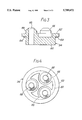
- FIG. 3 is a cross-section, to an enlarged scale, of the sealing element utilised in the arrangement of FIG. 2;
- FIG. 4 is a plan elevation of the sealing element shown in FIG. 3;
- FIG. 5 is a part view from FIG. 2, to an enlarged scale.
- FIG. 1 there is shown a meter assembly according to the prior art.
- a metal, cup-shaped housing 10 provides an enclosure for the register or metering unit 11.
- the assembly is closed by a domed polycarbonate cover 12 having an integral mounting flange 14. This is received within a lip 16 of the metal housing.
- a J-section seal 18 is interposed between the plastics cover and the metal housing to provide a vapour proof seal.
- a series of, typically, three terminals 20 are insert moulded into the plastics cover 12. These provide electrical connection to the internal encoding circuitry (not shown).
- the transparent plastics cover enables visual inspection of the number wheel or other display (not shown).
- vapour transmission paths arise in two ways. First, the polycarbonate cover is not totally impervious to water vapour. Second, differential thermal expansion between the terminals and the surrounding regions of the polycarbonate cover may lead to vapour paths opening as temperature cycles.
- the present invention involves a radical shift in thinking. Instead of adding further laminate to the plastic cover to reduce vapour permeability or taking steps to protect circuitry from vapour which unavoidably enters the enclosure, this invention proposes a return to glass. Surprisingly, it has been recognised that with an appropriate sealing arrangement, terminals can pass through a simple aperture machined or otherwise formed in the glass cover.
- FIG. 2 there is shown a metering assembly in accordance with the present invention.
- the polycarbonate cover of the prior art is replaced by a moulded glass cover 30.
- borosilicate glass was selected for its vapour transmission barrier properties, moulding capabilities, mechanical strength, thermo-dimensional stability and optical transmissivity. Borosilicate glass is also resistant to chemical attack.
- the choice of wall thickness for the glass cover is a compromise of cost against mechanical strength; in this example a wall thickness of 5 to 6 mm is employed.
- the glass cover is moulded with a blind recess. This enables a drilled hole to be initiated below the surface of the glass to produce the required aperture 32 whilst leaving the margin of the aperture smooth and undamaged.
- a rubber grommet 34 is located within the aperture 32 as an interference fit.
- Ethylene propylene rubber (EPR or EPDM) was selected as the preferred rubber material for its excellent resistance to weathering, ozone and water vapour permeation; good low and high temperature capabilities; excellent resistance to set and good resilience. Whilst this is the preferred choice, it will be recognised that a wide variety of other rubbers or other resilient materials could be employed.
- the grommet 34 is effectively sandwiched between an outer sealing plate 36 and an inner sealing plate 38. As will later be described in more detail, these are brought together in a clamping action by tightening of the nut 48 on terminal shank 50, with each terminal head 52 being held captive within a complimentarily shaped recess 54 in the outer sealing plate 36.
- grommet 34 is seen most clearly from the component drawings at FIGS. 3 and 4.
- the grommet 34 has a cylindrical portion 60 with a flange 62.
- An annular projection 64 is provided at the underside of the flange 62, essentially forming a sealing ring.
- Three bosses 66 equally angularly spaced, extend upwardly. Coaxial with each boss 66, is a terminal bore 68 which passes axially through the grommet. The upper surface of each boss 66 is chamfered.
- FIG. 5 shows the sealing arrangement of FIG. 2, to an enlarged scale.
- the outer sealing plate 36 has three hexagonal recesses 54, shaped to capture the head 52 of each terminal.
- the recesses 54 open into holes 56 which in turn open into a disk shaped cavity 58 bounded by an annular skirt 70.
- the lower sealing plate 38 takes the form of a disk with three holes 72 receiving the respective terminals 50.
- a nut 48 screw threadedly engaged with the end of each terminal 50, completes the structure.
- the rubber grommet 34 is first engaged as an interference fit within the aperture 32.
- the flange 62 overlies the glass 30 at the margin of the aperture with contact confined to the sealing ring 64.
- the outer sealing plate 36 is placed over the grommet 34 with the flange 62 being received in recess 58 and with each boss 66 extending through the corresponding terminal hole 56 and entering the hexagonal recess 54.
- the three terminals 50 are then inserted through the holes in the outer sealing plate 36 and the aligned bores 64 in the grommet.
- the central shank portion of each terminal is arranged to provide an interference fit within the grommet bore 68. If it is necessary to facilitate insertion, the terminals can be pre-greased with, for example, a silicon based grease.
- the hexagonal bolt heads 52 of the terminals are captive in the hexagonal recesses 54 and rest on the chamfered extremities of the respective bosses 66.
- the inner sealing plate 38 is offered over the screw threaded terminal ends 50 and the nuts 48 are engaged and tightened.
- the inner sealing plate 34 engages hard against the interior glass surface and each terminal head 52 is forced to the bottom of the associated recess 54, compressing the bosses 66. This effects a seal about each terminal shank.
- the outer sealing plate 36 is drawn towards the exterior glass surface so compressing the flange 62 and flattening the sealing ring 64.
- sealing is effected at the exterior surface of the glass cover. This, as noted above, is left blemish free in the manufacturing process so as to promote good sealing. Importantly, the thickness of the glass cover is not a material factor in the sealing. Relatively wide tolerances in the thickness can therefore be accommodated. It is also important to note that sealing is not dependent upon an attempt to compress solid rubber or other grommet material.
Abstract
Description
Claims (15)
Applications Claiming Priority (3)
| Application Number | Priority Date | Filing Date | Title |
|---|---|---|---|
| GB929212465A GB9212465D0 (en) | 1992-06-12 | 1992-06-12 | Vapour barrier |
| GB9212465 | 1992-06-12 | ||
| PCT/GB1993/001246 WO1993025867A1 (en) | 1992-06-12 | 1993-06-11 | Vapour barrier |
Publications (1)
| Publication Number | Publication Date |
|---|---|
| US5789672A true US5789672A (en) | 1998-08-04 |
Family
ID=10716966
Family Applications (1)
| Application Number | Title | Priority Date | Filing Date |
|---|---|---|---|
| US08/351,346 Expired - Lifetime US5789672A (en) | 1992-06-12 | 1993-06-11 | Metering assembly with vapor barrier |
Country Status (8)
| Country | Link |
|---|---|
| US (1) | US5789672A (en) |
| EP (1) | EP0644998B1 (en) |
| AT (1) | ATE163088T1 (en) |
| AU (1) | AU674857B2 (en) |
| CA (1) | CA2137570C (en) |
| DE (1) | DE69316891T2 (en) |
| GB (1) | GB9212465D0 (en) |
| WO (1) | WO1993025867A1 (en) |
Cited By (10)
| Publication number | Priority date | Publication date | Assignee | Title |
|---|---|---|---|---|
| US6522124B1 (en) | 2000-11-01 | 2003-02-18 | Schlumberger Resource Management Services, Inc. | Snap connecting inner modules for an electric utility meter |
| US20040056807A1 (en) * | 2001-03-09 | 2004-03-25 | Dan Winter | Meter register |
| US20050007260A1 (en) * | 2003-06-13 | 2005-01-13 | Dan Winter | Meter register and remote meter reader utilizing a stepper motor |
| US6885185B1 (en) | 1998-12-01 | 2005-04-26 | Itron Electricity Metering, Inc. | Modular meter configuration and methodology |
| US6904385B1 (en) * | 1998-05-29 | 2005-06-07 | Powerweb, Inc. | Multi-utility energy control system with internet energy platform having diverse energy-related engines |
| FR2868530A1 (en) * | 2004-03-30 | 2005-10-07 | Actaris | ARRANGEMENT FOR FASTENING A DEVICE ON THE HOOD OF A FLUID COUNTER. |
| US20060162467A1 (en) * | 2004-09-23 | 2006-07-27 | Arad Measuring Technologies, Ltd. | Meter register having an encoder |
| US20120312704A1 (en) * | 2010-03-15 | 2012-12-13 | Patrick Rolland | Package having opening detection |
| US20170176232A1 (en) * | 2014-08-14 | 2017-06-22 | RG5 Meter Company, (dba RG-3) | Perpetual Meter with Noise Damping |
| US20220146283A1 (en) * | 2020-11-12 | 2022-05-12 | Das Technology Co., Ltd. | Monitoring device of water meter |
Families Citing this family (3)
| Publication number | Priority date | Publication date | Assignee | Title |
|---|---|---|---|---|
| ES2066723B1 (en) * | 1993-05-25 | 1995-11-01 | Contadores De Agua De Zaragoza | IMPROVEMENTS FOR FLUID METERS. |
| US6121865A (en) * | 1998-08-03 | 2000-09-19 | Caterpillar Inc. | Solenoid assembly having a sealing device for the electrical leads |
| EP4107819A1 (en) * | 2020-02-18 | 2022-12-28 | Micro Motion, Inc. | Assemblies, components, and methods for creating a flameproof or explosion proof barrier |
Citations (12)
| Publication number | Priority date | Publication date | Assignee | Title |
|---|---|---|---|---|
| US3093973A (en) * | 1959-06-29 | 1963-06-18 | Chemetron Corp | System for metering liquefied gas |
| US3576555A (en) * | 1967-09-12 | 1971-04-27 | Sangamo Electric Co | Meter dial extension system |
| US3599022A (en) * | 1970-07-07 | 1971-08-10 | Singer Co | Impulse generator for meters |
| DE1774578A1 (en) * | 1968-07-19 | 1972-02-03 | Bopp & Reuther Gmbh | Remote transmission of measurement results, especially for liquid counters |
| US3720106A (en) * | 1967-08-25 | 1973-03-13 | A Varga | Fluid meter |
| US3731534A (en) * | 1970-11-18 | 1973-05-08 | Rockwell Mfg Co | Housing structure for meters |
| US3829775A (en) * | 1972-01-28 | 1974-08-13 | G Brock | Meter with electrically selectable scales |
| US4063661A (en) * | 1975-02-18 | 1977-12-20 | Westinghouse Electric Corporation | Electric load research device including an enclosure having adjustable meter positions |
| US4581933A (en) * | 1985-02-04 | 1986-04-15 | Penn Airborne Products Company | Aircraft casing indicator seal |
| WO1988007780A1 (en) * | 1987-03-23 | 1988-10-06 | Abl Arbetsbelysning Ab | Arrangement for an opening |
| US5049810A (en) * | 1989-09-22 | 1991-09-17 | Landis & Gyr Metering, Inc. | Watt-hour meter cover with battery hatch reset switch and optical communication port |
| US5057767A (en) * | 1990-04-05 | 1991-10-15 | General Electric Company | Optical communications light shield for energy meter |
-
1992
- 1992-06-12 GB GB929212465A patent/GB9212465D0/en active Pending
-
1993
- 1993-06-11 CA CA002137570A patent/CA2137570C/en not_active Expired - Lifetime
- 1993-06-11 US US08/351,346 patent/US5789672A/en not_active Expired - Lifetime
- 1993-06-11 AT AT93913349T patent/ATE163088T1/en not_active IP Right Cessation
- 1993-06-11 DE DE69316891T patent/DE69316891T2/en not_active Expired - Lifetime
- 1993-06-11 EP EP93913349A patent/EP0644998B1/en not_active Expired - Lifetime
- 1993-06-11 AU AU43455/93A patent/AU674857B2/en not_active Ceased
- 1993-06-11 WO PCT/GB1993/001246 patent/WO1993025867A1/en active IP Right Grant
Patent Citations (12)
| Publication number | Priority date | Publication date | Assignee | Title |
|---|---|---|---|---|
| US3093973A (en) * | 1959-06-29 | 1963-06-18 | Chemetron Corp | System for metering liquefied gas |
| US3720106A (en) * | 1967-08-25 | 1973-03-13 | A Varga | Fluid meter |
| US3576555A (en) * | 1967-09-12 | 1971-04-27 | Sangamo Electric Co | Meter dial extension system |
| DE1774578A1 (en) * | 1968-07-19 | 1972-02-03 | Bopp & Reuther Gmbh | Remote transmission of measurement results, especially for liquid counters |
| US3599022A (en) * | 1970-07-07 | 1971-08-10 | Singer Co | Impulse generator for meters |
| US3731534A (en) * | 1970-11-18 | 1973-05-08 | Rockwell Mfg Co | Housing structure for meters |
| US3829775A (en) * | 1972-01-28 | 1974-08-13 | G Brock | Meter with electrically selectable scales |
| US4063661A (en) * | 1975-02-18 | 1977-12-20 | Westinghouse Electric Corporation | Electric load research device including an enclosure having adjustable meter positions |
| US4581933A (en) * | 1985-02-04 | 1986-04-15 | Penn Airborne Products Company | Aircraft casing indicator seal |
| WO1988007780A1 (en) * | 1987-03-23 | 1988-10-06 | Abl Arbetsbelysning Ab | Arrangement for an opening |
| US5049810A (en) * | 1989-09-22 | 1991-09-17 | Landis & Gyr Metering, Inc. | Watt-hour meter cover with battery hatch reset switch and optical communication port |
| US5057767A (en) * | 1990-04-05 | 1991-10-15 | General Electric Company | Optical communications light shield for energy meter |
Cited By (30)
| Publication number | Priority date | Publication date | Assignee | Title |
|---|---|---|---|---|
| US6904385B1 (en) * | 1998-05-29 | 2005-06-07 | Powerweb, Inc. | Multi-utility energy control system with internet energy platform having diverse energy-related engines |
| US7701199B2 (en) | 1998-12-01 | 2010-04-20 | Itron, Inc. | Modular meter configuration and methodology |
| US20050162149A1 (en) * | 1998-12-01 | 2005-07-28 | Makinson David N. | Modular meter configuration and methodology |
| US6885185B1 (en) | 1998-12-01 | 2005-04-26 | Itron Electricity Metering, Inc. | Modular meter configuration and methodology |
| US6522124B1 (en) | 2000-11-01 | 2003-02-18 | Schlumberger Resource Management Services, Inc. | Snap connecting inner modules for an electric utility meter |
| US7343795B2 (en) | 2001-03-09 | 2008-03-18 | Arad Measuring Technologies Ltd | Meter register and meter register tampering detector |
| US20040056807A1 (en) * | 2001-03-09 | 2004-03-25 | Dan Winter | Meter register |
| US20050212710A1 (en) * | 2001-03-09 | 2005-09-29 | Arad Measuring Technologies, Ltd. | Meter register |
| USRE47407E1 (en) | 2001-03-09 | 2019-05-28 | Arad Measuring Technologies Ltd. | Meter register transmitting flow rate warning |
| US6954178B2 (en) | 2001-03-09 | 2005-10-11 | Arad Measuring Technologies, Ltd. | Meter register |
| US8109131B2 (en) | 2001-03-09 | 2012-02-07 | Arad Measuring Technologies Ltd. | Meter register transmitting flow rate warning |
| US10330507B2 (en) | 2001-03-09 | 2019-06-25 | Arad Measuring Technologies Ltd. | Meter register and utility meter having wireless remote reading arrangement |
| US7126551B2 (en) | 2001-03-09 | 2006-10-24 | Arad Measuring Technologies Ltd | Meter register |
| US20070109209A1 (en) * | 2001-03-09 | 2007-05-17 | Arad Measuring Technologies Ltd. | Meter register |
| US6819292B2 (en) | 2001-03-09 | 2004-11-16 | Arad Measuring Technologies Ltd | Meter register |
| US9356334B2 (en) | 2001-03-09 | 2016-05-31 | Arad Measuring Technologies Ltd. | Meter register transmitting flow rate warning |
| US20080209985A1 (en) * | 2001-03-09 | 2008-09-04 | Arad Measuring Technologies Ltd. | Meter register |
| US7775422B2 (en) | 2003-06-13 | 2010-08-17 | Arad Measuring Technologies Ltd. | Meter register and remote meter reader utilizing a stepper motor |
| US20050007260A1 (en) * | 2003-06-13 | 2005-01-13 | Dan Winter | Meter register and remote meter reader utilizing a stepper motor |
| US8157160B2 (en) | 2003-06-13 | 2012-04-17 | Arad Measuring Technologies Ltd. | Meter register and remote meter reader utilizing a stepper motor |
| US8448845B2 (en) | 2003-06-13 | 2013-05-28 | Arad Measuring Technologies Ltd. | Meter register and remote meter reader utilizing a stepper motor |
| EP1586869A1 (en) | 2004-03-30 | 2005-10-19 | Actaris SAS | Unit for fixing of a device on the cap of a flowmeter |
| FR2868530A1 (en) * | 2004-03-30 | 2005-10-07 | Actaris | ARRANGEMENT FOR FASTENING A DEVICE ON THE HOOD OF A FLUID COUNTER. |
| US7267014B2 (en) | 2004-09-23 | 2007-09-11 | Arad Measuring Technologies Ltd. | Meter register having an encoder |
| US20060162467A1 (en) * | 2004-09-23 | 2006-07-27 | Arad Measuring Technologies, Ltd. | Meter register having an encoder |
| US9404944B2 (en) * | 2010-03-15 | 2016-08-02 | Sagamcom Energy & Telecom Sas | Package having opening detection |
| US20120312704A1 (en) * | 2010-03-15 | 2012-12-13 | Patrick Rolland | Package having opening detection |
| US20170176232A1 (en) * | 2014-08-14 | 2017-06-22 | RG5 Meter Company, (dba RG-3) | Perpetual Meter with Noise Damping |
| US10006794B2 (en) * | 2014-08-14 | 2018-06-26 | Michael Lee Gregory | Perpetual meter with noise damping |
| US20220146283A1 (en) * | 2020-11-12 | 2022-05-12 | Das Technology Co., Ltd. | Monitoring device of water meter |
Also Published As
| Publication number | Publication date |
|---|---|
| CA2137570C (en) | 2004-11-02 |
| AU4345593A (en) | 1994-01-04 |
| CA2137570A1 (en) | 1993-12-23 |
| ATE163088T1 (en) | 1998-02-15 |
| WO1993025867A1 (en) | 1993-12-23 |
| DE69316891D1 (en) | 1998-03-12 |
| EP0644998A1 (en) | 1995-03-29 |
| AU674857B2 (en) | 1997-01-16 |
| GB9212465D0 (en) | 1992-07-22 |
| EP0644998B1 (en) | 1998-02-04 |
| DE69316891T2 (en) | 1998-05-28 |
Similar Documents
| Publication | Publication Date | Title |
|---|---|---|
| US5789672A (en) | Metering assembly with vapor barrier | |
| US5821695A (en) | Encapsulated explosion-proof pilot light | |
| US4958938A (en) | Temperature transmitter with integral secondary seal | |
| KR20040111322A (en) | Pressure measuring device | |
| EP0775292A1 (en) | Transmitter with moisture draining housing and improved method of mounting rfi filters | |
| RU2628759C2 (en) | Dual-chamber protection against environment | |
| CN100565151C (en) | The relative pressure measuring transducer | |
| US20050250371A1 (en) | Sealing structure for connector | |
| KR101799490B1 (en) | Explosion-proof junction box | |
| JP2014220054A (en) | Waterproof main terminal | |
| US5365785A (en) | Submersible meter register case and assembly | |
| JP2005188517A (en) | Electric component protecting device | |
| US7699537B2 (en) | Optical port apparatus and method of making the same | |
| US20060131141A1 (en) | Composite cover with electrical bridge | |
| JPH11118649A (en) | Pressure oscillator | |
| TW351820B (en) | Process for fabricating test switch casing and method thereof | |
| US2847498A (en) | Disengageable hermetically sealled closure for electrical and electronic components | |
| CN216559166U (en) | Camera shooting instrument suitable for severe environment | |
| CN116754028A (en) | Flowmeter and flow detection device | |
| JP2720940B2 (en) | Electrical parts storage case | |
| KR102405224B1 (en) | Device for integrated type valve panel of underground box | |
| CN218038738U (en) | Combined type casting explosion-proof electromagnetic coil | |
| JPH0843232A (en) | Pressure sensor | |
| JP2720939B2 (en) | Electrical parts storage case | |
| CN101692564A (en) | Connection box and connection assembly comprising such a box |
Legal Events
| Date | Code | Title | Description |
|---|---|---|---|
| AS | Assignment |
Owner name: ABB KENT PLC, ENGLAND Free format text: ASSIGNMENT OF ASSIGNORS INTEREST;ASSIGNORS:ROGERS, IVOR THOMAS;SAMUEL, WAYNE DAVID;REEL/FRAME:007339/0346;SIGNING DATES FROM 19940311 TO 19941028 |
|
| STCF | Information on status: patent grant |
Free format text: PATENTED CASE |
|
| FPAY | Fee payment |
Year of fee payment: 4 |
|
| SULP | Surcharge for late payment | ||
| REMI | Maintenance fee reminder mailed | ||
| FPAY | Fee payment |
Year of fee payment: 8 |
|
| SULP | Surcharge for late payment |
Year of fee payment: 7 |
|
| AS | Assignment |
Owner name: ABB METERING HOLDINGS LIMITED, UNITED KINGDOM Free format text: CHANGE OF NAME;ASSIGNOR:ABB KENT PLC;REEL/FRAME:019580/0670 Effective date: 19990111 |
|
| AS | Assignment |
Owner name: ELSTER METERING HOLDINGS LIMITED, UNITED KINGDOM Free format text: CHANGE OF NAME;ASSIGNOR:ABB METERING HOLDINGS LIMITED;REEL/FRAME:019597/0957 Effective date: 20021205 |
|
| FPAY | Fee payment |
Year of fee payment: 12 |