US5790658A - High performance echo canceller for high speed modem - Google Patents
High performance echo canceller for high speed modem Download PDFInfo
- Publication number
- US5790658A US5790658A US08/739,009 US73900996A US5790658A US 5790658 A US5790658 A US 5790658A US 73900996 A US73900996 A US 73900996A US 5790658 A US5790658 A US 5790658A
- Authority
- US
- United States
- Prior art keywords
- echo
- signal
- filter
- coupled
- analytic
- Prior art date
- Legal status (The legal status is an assumption and is not a legal conclusion. Google has not performed a legal analysis and makes no representation as to the accuracy of the status listed.)
- Expired - Lifetime
Links
Images


Classifications
-
- H—ELECTRICITY
- H04—ELECTRIC COMMUNICATION TECHNIQUE
- H04B—TRANSMISSION
- H04B3/00—Line transmission systems
- H04B3/02—Details
- H04B3/20—Reducing echo effects or singing; Opening or closing transmitting path; Conditioning for transmission in one direction or the other
- H04B3/23—Reducing echo effects or singing; Opening or closing transmitting path; Conditioning for transmission in one direction or the other using a replica of transmitted signal in the time domain, e.g. echo cancellers
- H04B3/237—Reducing echo effects or singing; Opening or closing transmitting path; Conditioning for transmission in one direction or the other using a replica of transmitted signal in the time domain, e.g. echo cancellers using two adaptive filters, e.g. for near end and for end echo cancelling
Definitions
- This invention is related to the field of echo cancellation in communication networks employing hybrid transformers, and more particularly to an echo cancellation system that uses more than one adaptation stage for training echo cancellation filters.
- Telephone networks commonly employ two-wire bi-directional communication lines which connect a subscriber, such as a telephone set in a home or office, to the network central office.
- two-wire bi-directional communication lines are used in the subscriber loop for reduced cost.
- other communication paths in the telephone network such as trunks between central offices, use four-wire communication lines.
- Four-wire communication lines have separate transmit and receive paths and provide better transmission quality due to the fact that each path may be separately optimized.
- Another advantage of four-wire lines is that communication techniques such as frequency division multiplexing (FDM), which require separate transmit and receive paths, may be employed.
- FDM frequency division multiplexing
- Central office line controller circuits frequently use hybrid transformers to provide two-wire to four-wire circuit conversion.
- Hybrid transformers are also widely used in digital terminal equipment such as digital cordless telephone base stations, digital telephone answering devices, etc.
- a hybrid transformer With the use of a hybrid transformer, four-wire communication lines may be used in most of the telephone network, providing increased transmission quality while less expensive two-wire lines are principally used in the subscriber loop.
- the problem of impedance mismatch is introduced at the two-wire to four-wire interfaces, namely at the hybrids. This impedance mismatch results in the transmit path signal reflecting back to the receive path at the conversion point. This reflection introduced primarily in the hybrid is commonly referred to as "echo".
- the amount of echo a hybrid generates depends on the ability of the hybrid to separate the receive and transmit paths and the line load conditions. On a long, heavily loaded loop, the echo effect will be larger. Typical echo is about 10 to 16 dB below the source signal without an echo canceler.
- Echo can originate not only from reflection on the line but also acoustic reflection (e.g., speaker phone application). Whatever the source of echo, the result is annoying to the user. Not only might the user hear an echo of his or her voice, but worse yet, may be incapable of effectively receiving certain remote commends. A problem known as "double talking" may occur which can deleteriously effect reception of certain remote commands. Double-talking occurs where the communication line is transmitting and receiving simultaneously.
- DTMF dual-tone multifrequency
- the answering machine When the answering machine is in playback mode, the played speech on the transmit path echoes back to the receive path. If the user at a remote telephone is also entering DTMF commands, this may cause the DTMF detector to not be able to detect the remote DTMF commands. In other words, if speech is being played, such as the answering machine greeting or a recorded message, and is echoed back to the answer machine, and if the DTMF detector is receiving tones, the DTMF detector may have difficulty detecting the DTMF signals which are mixed with the presence of speech. As a result, the answering machine may miss the command. Hence, employment of an echo canceler in this case would be useful.
- Prior art echo cancellation methods include measuring the impulse response of the hybrid and then constructing a balancing filter that has the same characteristics as the hybrid.
- the filter receives the transmit path signal and generates an estimate of the echo.
- the echo estimate is subtracted from the actual received signal. The result is the echo canceled transmit signal.
- a balancing filter which performs echo cancellation (hereafter, also called an echo canceling filter) can be readily produced given the fixed characteristics under which the filter operates.
- an echo canceling filter which performs echo cancellation
- An adaptive balancing filter updates its coefficients based on the transmit path signal and an error signal.
- a commonly used error signal is the difference between the actual received signal and the echo estimate.
- the update process by which the filter coefficients are repeatedly adjusted to eventually match the network conditions and thereafter track the conditions as they change is known as the convergence process.
- the state of the filter when the coefficients have substantially achieved their optimal values is herein referred to as the convergence point.
- the abbreviated term "convergence" is commonly used to refer to both the convergence process and the convergence point, and the exact meaning must be determined from the context in which it is used. The use of the abbreviated term will be avoided herein.
- LMS least mean square
- the convergence speed determines the average time for the filter coefficients to reach the convergence point given a "distance" between the current state and the convergence point. A higher convergence speed provides a smaller time to reach the convergence point.
- a second criteria is the signal to distortion ratio (SDR), which is expressed as a ratio of signal power to distortion power.
- the distortion power may be estimated by comparing the received signal to a theoretical ideal calculated assuming no channel noise and no echo components.
- the following equation measures the echo cancellation accuracy: ##EQU1##
- r(n) is the sampled receive signal
- d(n) is the difference between the sampled received signal and the theoretical ideal
- n is a sample index
- N is the measurement frame size.
- SDR signal to distortion ratio
- the filter coefficients are calculated using:
- n is a sample index
- W k ( ) is a filter coefficient
- u 1 and u 2 are step sizes
- e( ) is an error signal
- x( ) is the sampled transmit path signal
- k signifies one of the filter coefficients
- N is the number of filter coefficients
- sign( ) takes an algebraic sign of its argument.
- the step size used is a crucial factor in determining the convergence speed and stability of the filter. If the step size is too large, the noise added into the operation will cause the adaptive algorithm to diverge. On the other hand, if the step size is too small, the filter coefficients may take a long time to converge.
- the coefficient update value which is the product of the step size and error value, becomes a value which is smaller than the smallest difference between possible fixed precision coefficient values.
- the step size of an LMS algorithm is upper bounded by twice the reciprocal of the largest eigenvalue ⁇ max of the correlation matrix of the transmit path signal.
- the step size also has a lower bound, determined by quantization of the update value of the filter coefficients. To ensure the filter coefficient values are updated, the update must be larger than the smallest quantization value of the update.
- the condition under which the i th coefficient of the balance filter stops updating is:
- step size u is the step size
- e( ) is the sampled error signal
- x( ) is the sampled transmit path signal
- ⁇ is the increment between two consecutive legal quantizer output levels.
- the lower bound on step size u is then given by: ##EQU2## where ⁇ x 2 is the average power of transmit path signal, and ⁇ min is the minimum power of the error signal at steady state, that is, at the convergence point.
- the convergence speed of the LMS algorithm, t is inversely proportional to the step size ⁇ : ##EQU3## wherein ⁇ min represents the smallest eigenvalue of the correlation matrix of the transmit path signal. It should be noted that a trade-off exists in the choice of the step size. Within the allowed range of step sizes, a larger step size leads to a reduced time for reaching the convergence point, but a smaller step size provides for a reduced variation in the steady state estimate. Hence, a more accurate estimation of the filter coefficients is provided by a smaller step size. However, because the accuracy which is achievable by simply reducing the step size is often insufficient, other avenues must be explored.
- an architecture that includes a multi-stage adaptation algorithm which operates on echo cancellation filters of different configurations.
- the resulting architecture gains an increased estimation accuracy. The increased accuracy readily translates into improved echo cancellation performances.
- the present invention comprises a system and method for performing echo cancellation in a communications network which experiences reflections of a transmit signal which interfere with a receive signal during full-duplex operation.
- the system includes an echo canceler with a passband signal filter configuration and a baseband signal filter configuration.
- Each filter configuration has its own adaptation algorithm module. The increased sensitivity of the baseband signal filter configuration to the estimation of an offset frequency is used to provide an accurately estimated parameter to the passband signal filter configuration, thereby allowing improved echo cancellation performance by the passband filter configuration.
- the present invention further contemplates a modem with echo canceling ability, wherein the echo canceling ability is provided by more than one echo canceling filter configuration.
- the modem comprises an adaptive baseband filter configuration and an adaptive passband filter configuration.
- the adaptive passband filter configuration achieves an improved echo cancellation performance in part due to a more accurate estimate of an offset frequency parameter provided by the adaptive baseband filter configuration.
- FIG. 1 is a signal flow diagram of a communications network using echo cancellation
- FIG. 2 is a block diagram of a first embodiment of a digital modem with an echo canceler
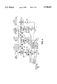
- FIG. 3 is a block diagram of a second embodiment of a digital modem with an improved high performance echo canceler.
- FIG. 1 an idealized signal flow diagram of a communications network is shown. This configuration serves to deliver data from a local input terminal 114 to a remote output terminal 116 while simultaneously delivering data from remote input terminal 118 to local output terminal 120.
- a local modem 100 is coupled to a remote modem 102 via communications channel comprised of a local two-wire bi-directional signal path 104, a local hybrid 106, a four-wire signal path 108, a remote hybrid 110, and a remote two-wire bi-directional signal path 112.
- Local modem 100 comprises a transmitter 122 coupled to receive data from local input terminal 114 and configured to deliver a transmit signal representative of input data via a hybrid transformer 124 to the communications channel described previously.
- Local modem 100 further comprises a receiver 126 coupled to accept a receive signal delivered via hybrid transformer 124 from the communications channel described previously.
- Hybrid transformer 124 is necessary for full-duplex operation of local modem 100 on local two-wire bi-directional signal path 104. Due to reasons which will be discussed below, it is expected that the receive signal will contain an echo of the transmit signal. It being advantageous to have the echo removed, local modem 100 further comprises echo canceler 128. Echo canceler 128 is coupled to receive data from local input terminal 114 and configured to deliver a replica of the echo contained in the receive signal.
- echo canceler 128 adjusts the coefficients of an adaptive balancing filter in accordance with an algorithm responsive to the receive signal.
- a summer 130 is coupled to accept the echo replica from echo canceler 128 and configured to subtract the echo replica from the receive signal thereby "canceling" the echo contained in the receive signal.
- Local hybrid 106 functions as an interface between local two-wire bi-directional signal path 104 and four-wire signal path 108.
- the transmit signal and the receive signal are each carried in isolation.
- the isolation is provided by two uni-directional two-wire signal paths which make up the four-wire signal path.
- An inductive coupling provided by the hybrid is designed to preserve this isolation while permitting transfer of the receive and transmit signals to and from a bi-directional two-wire signal path. All hybrids in the communications network are designed to function in this manner. However, impedance mismatches occur at the interfaces in the hybrid which in effect undermine the isolation and allow signal coupling between the transmit and receive paths. This coupling creates an echo of the transmit signal which returns along the receive path as part of the receive signal.
- the plurality of hybrids creates a multiplicity of echoes, but the overall accumulation of echoes appears essentially as two smeared echoes.
- the two echoes are separated in time.
- the first echo is attributable to coupling in the local part of the channel, and is commonly termed the “near echo”.
- the second echo is attributable to coupling in the remote part of the channel and is commonly termed the "far echo".
- the signals which pass through only the local part of the communications channel experience very little in the way of nonlinear effects. For this reason, the near echo may be accurately expressed as a linear function of the transmit signal.
- signaling across the four-wire portion of the channel is often done using nonlinear modulation techniques.
- the far echo which is generated by remote portions of the channel often experiences a nonlinear transformation.
- This transformation can be well approximated as a modulation of the input symbols by a different carrier frequency.
- This new carrier frequency is typically expressed relative to the original carrier frequency, i.e. as a frequency offset.
- One further characteristic of the far echo is that typically it is greatly attenuated relative to the near echo.
- local modem 100 further comprises an adaptive algorithm module 132.
- Adaptive algorithm module 132 is coupled to accept the output of summer 130 and thereafter apply an adaptation update to echo canceler 128.
- the adaptation is governed by an algorithm such as the LMS algorithm described previously.
- the adaptive update is therefore based on the previous echo-canceled output from summer 130.
- the update occurs through the feedback arrangements shown.
- the signal lines depicted inside modem 100 are generic in the sense that they may be used to carry either real-valued or complex-valued signals.
- Complex numbers are numbers having a real component and an imaginary component.
- Complex values are a common way of representing two-dimensional signals such as those used for quadrature amplitude modulation (QAM) and quadrature phase-shift keying (QPSK).
- QAM quadrature amplitude modulation
- QPSK quadrature phase-shift keying
- complex-valued signals will be carried by a pair of signal lines, while real values signals will be carried by a single signal line.
- the echo replica signal shown actually comprises two signals, a near echo replica signal and a far echo replica signal. Consequently, though the FIG.
- symbol is herein used to refer to a discrete-time, discrete-amplitude signal (i.e. a sample of a digital signal). This usage follows from the ability to represent a digital signal as a sequence of symbols.
- FIG. 2 a block diagram of one embodiment of a digital modem with echo cancellation is shown.
- Two-dimensional input symbols 114 are accepted by transmitter 122 which then generates a digital transmit signal.
- the digital transmit signal is then converted to a continuous time transmit signal via digital-to-analog (D/A) converter 134 and bandpass filter 136.
- the continuous time transmit signal is then coupled to local two-wire bi-directional signal path 104 by hybrid 124.
- Hybrid 124 also couples a continuous time receive signal from local two-wire bi-directional signal path 104.
- the continuous time receive signal is converted to a digital receive signal via a bandpass filter 138 and an analog-to-digital (A/D) converter 140.
- A/D converter is sampling at some multiple n of the symbol rate. The higher sampling frequency is implemented to avoid a requirement for clock synchronization prior to echo cancellation.
- the digital receive signal is coupled to a Hilbert transform filter 142 which provides an analytic receive signal.
- a bandpass signal may be represented as the real part of an analytic signal that expresses the quadrature components of the bandpass signal as a complex-valued signal. See, e.g., Jean-Jacques Werner, "An Echo-Cancellation-Based 4800 Bit/s Full-Duplex DDD Modem," IEEE J. Selected Areas in Communications, vol. 2, no. 5, pp. 722-730, Sept. 1984; and Stephen B. Weinstein, "A Passband Data-Driven Echo Canceller for Full-Duplex Transmission on Two-Wire Circuits," IEEE Trans. Communications, vol. 25, no. 7, pp. 654-666, Jul.
- Echo canceler 128 comprises a symbol buffer 144 coupled to accept input symbols 114. Symbols from buffer 144 are modulated, or "rotated", by multiplication 146 with a complex sinusoid.
- the complex sinusoid oscillates at the carrier frequency ⁇ c/ 2 ⁇ and progresses in time steps of nT where T is the sampling period of A/D converter 140 and n is the number of samples per symbol period. This allows for a reduced implementation complexities of filters discussed below. Details of reduced complexity filter implementation are set forth in the Werner article incorporated herein.
- the rotated symbols are held in a symbol buffer 148 for usage by a near-echo canceler 150.
- the rotated symbols are subsequently rotated a second time by a multiplication 152 with a second complex sinusoid.
- the second complex sinusoid oscillates at an adaptively determined offset frequency ⁇ off /2 ⁇ and progresses in time steps of (n-D)T where D is the measured delay of the second echo.
- the twice-rotated signals are held in a symbol buffer 154 for usage by far-echo canceler 156.
- Near echo canceler 150 is coupled to receive rotated symbols from buffer 148.
- Near echo canceler 150 takes the form of a linear filter with adjustable coefficients. The coefficients form an approximation of the channel response experienced by the modulated input symbols as they pass from the transmitter across the local part of the communications channel and echo back to the receiver. By convolving (i.e. filtering) the sequence of rotated symbols with the channel response, the near echo canceler generates a replica of the near echo.
- Far echo canceler 156 is coupled to receive rotated symbols from buffer 154.
- Far echo canceler 156 takes the form of a linear filter with adjustable coefficients. The coefficients form an approximation of the channel response experienced by the modulated input symbols as they pass from the transmitter to the remote part of the communications channel and echo back to the receiver. By convolving the sequence of rotated symbols with the channel response, the far echo canceler generates a replica of the far echo.
- Summer 158 is coupled to add the replica of the near echo to the replica of the far echo and thereby generate a total echo signal.
- the total echo signal is then subtracted from the analytic receive signal by summer 160.
- the resulting echo-canceled signal is then coupled to a receiver for demodulation.
- An adaptation algorithm module (AAM) 132 is coupled to receive the echo canceled signal.
- the function of AAM 132 is to iteratively update the coefficients of near echo canceler 150 and far echo canceler 156 in such a way as to minimize any residual echo.
- AAM 132 is also used to adaptively update the estimate of ⁇ off .
- AAM 132 is typically implemented using some form of the LMS algorithm.
- the SDR For reliable information exchange, the SDR must be maintained above a predetermined level. One primary obstacle to achieving this level is inaccurate estimation of the frequency offset of the far echo. It should be noted that for the embodiment of FIG. 2, one error signal is being used to simultaneously update (1) the near echo coefficients, (2) the far echo coefficients, and (3) the offset frequency.
- the adaptation of items (2) and (3) is complicated by the 40 dB to 50 dB difference in power of the near and far echo components.
- the estimate of item (3) is further complicated by the inherent non-linearity of the phase-lock loop (PLL) which must be used.
- PLL phase-lock loop
- FIG. 3 a block diagram of a second embodiment of a digital modem with echo cancellation is shown which addresses the concerns expressed immediately above.
- the structure of this embodiment differs in the following ways: the use of the Hilbert transform filter (which serves to provide an analytic signal from a real valued signal) is deferred, and only the real part of the output of near echo canceler 150 and far echo canceler 156 are used for echo cancellation.
- Summers 158 and 160 operate to remove the echo from the digital receive signal and thereby produce a real-valued error signal.
- AAM 132 is split into two modules 132a and 132b.
- AAM 132a operates on the error signal to iteratively update the coefficients of near echo canceler 150 and far echo canceler 156.
- AAM 132a does not form an estimate of the offset frequency ( ⁇ off ). Rather, the offset frequency is obtained in a more accurate manner which will be described below. This allows for more accurate adaptation of the coefficients of far echo canceler 156.
- summer 162 is coupled to remove the replica of the near echo from the digital receive signal.
- the near-echo canceled signal is passed through Hilbert transform filter 142 to produce an analytic near-echo canceled signal.
- a summer 168 then removes an analytic far-echo signal from the analytic near-echo canceled signal to produce echo canceled signal 120.
- the analytic far-echo signal is generated by means of a second far echo canceler 164.
- Far echo canceler 164 is coupled directly to symbol buffer 144. Note that signal modulation does not occur prior to the filtering operation.
- Far echo canceler 164 takes the form of a linear filter with adjustable coefficients.
- the coefficients form an approximation of the channel response experienced by input symbols 114 as they pass through the transmitter to the remote part of the communications channel and echo back to the receiver.
- the far echo canceler By convolving the sequence of input symbols with the channel response, the far echo canceler generates an analytic low-pass replica of the far echo.
- the analytic low-pass replica is then modulated by a multiplication 166 with complex sinusoid.
- the complex sinusoid oscillates at the carrier frequency ( ⁇ c + ⁇ off ) /2 ⁇ and progresses in time steps of T.
- the resulting analytic far echo signal is coupled to summer 168.
- the second AAM 132b operates on the analytic error-canceled signal to iteratively update the coefficients of second far echo canceler 164.
- AAM 132b also generates an estimate of ⁇ off .
- the configuration of this adaptive loop with the modulation occurring after the filtering provides a higher sensitivity of the adaptation algorithm to ⁇ off , thereby permitting a high accuracy estimate of the offset frequency.
- the second adaptation loop since the near echo has been essentially removed, the second adaptation loop does not suffer the dominating interference of the near echo. This permits a more focused optimization of update parameters for adaptation of second far echo canceler coefficients.
- this embodiment achieves improved performance by splitting the adaptive algorithm module in the described manner.
- the second adaptation stage achieves a high accuracy estimation of the far echo characteristics and frequency offset due to the removal of the dominating influence of the near echo by the first stage.
- the first stage in turn achieves better performance by the better estimation of the frequency offset provided by the second stage.
- summer 130 is functionally replaced by two summers, summer 162 and summer 168.
- the output of summer 168 is forwarded to receiver 126.
Abstract
Description
w.sub.k (n+1)=w.sub.k (n)+u.sub.1 e(n)x(n-k), k=0, 1, . . . , N-1
w.sub.k (n+1)=w.sub.k (n)+u.sub.2 sign(e(n))sign(x(n-k)), k=0, 1, . . . , N-1
|u e(n)x(n-i)|<δ/2
Claims (8)
Priority Applications (1)
| Application Number | Priority Date | Filing Date | Title |
|---|---|---|---|
| US08/739,009 US5790658A (en) | 1996-10-28 | 1996-10-28 | High performance echo canceller for high speed modem |
Applications Claiming Priority (1)
| Application Number | Priority Date | Filing Date | Title |
|---|---|---|---|
| US08/739,009 US5790658A (en) | 1996-10-28 | 1996-10-28 | High performance echo canceller for high speed modem |
Publications (1)
| Publication Number | Publication Date |
|---|---|
| US5790658A true US5790658A (en) | 1998-08-04 |
Family
ID=24970431
Family Applications (1)
| Application Number | Title | Priority Date | Filing Date |
|---|---|---|---|
| US08/739,009 Expired - Lifetime US5790658A (en) | 1996-10-28 | 1996-10-28 | High performance echo canceller for high speed modem |
Country Status (1)
| Country | Link |
|---|---|
| US (1) | US5790658A (en) |
Cited By (55)
| Publication number | Priority date | Publication date | Assignee | Title |
|---|---|---|---|---|
| US20010002903A1 (en) * | 1999-12-07 | 2001-06-07 | Lg Electronics Inc. | DTMF transmission structure of W-CDMA WLL system |
| US6266367B1 (en) * | 1998-05-28 | 2001-07-24 | 3Com Corporation | Combined echo canceller and time domain equalizer |
| US6317494B1 (en) * | 1997-05-07 | 2001-11-13 | Agere Systems Guardian Corp. | Line-compensating codec |
| US6404809B1 (en) * | 1998-09-08 | 2002-06-11 | Conexant Systems, Inc. | Method and apparatus for training equalizer structures in a digital communication system having periodic digital impairments |
| US6577731B1 (en) * | 1998-09-02 | 2003-06-10 | Nec Corporation | Method and apparatus of cancelling multi-channel echoes |
| US20030108093A1 (en) * | 2001-12-10 | 2003-06-12 | Yhean-Sen Lai | Efficient PCM modem |
| US6754187B1 (en) | 2000-04-06 | 2004-06-22 | Inter-Tel, Inc. | Performance enhancement system for digital PBX |
| US6795405B1 (en) * | 1999-12-27 | 2004-09-21 | Telogy Networks, Inc. | Digital modem echo canceler enhancement |
| US6904088B1 (en) * | 2000-11-09 | 2005-06-07 | Texas Instruments Incorporated | Efficient equalization for detection of symbols in digital burst transmissions |
| US7023812B1 (en) | 2000-02-15 | 2006-04-04 | Siemens Communications, Inc. | System and method for improving modem transmission through private branch exchanges, central offices, and other systems |
| US7280060B1 (en) | 2000-05-23 | 2007-10-09 | Marvell International Ltd. | Communication driver |
| US7327995B1 (en) * | 2000-07-31 | 2008-02-05 | Marvell International Ltd. | Active resistance summer for a transformer hybrid |
| US7649483B1 (en) | 2000-05-23 | 2010-01-19 | Marvell International Ltd. | Communication driver |
| US7737788B1 (en) | 2005-08-09 | 2010-06-15 | Marvell International Ltd. | Cascode gain boosting system and method for a transmitter |
| US7761076B1 (en) | 2000-07-31 | 2010-07-20 | Marvell International Ltd. | Apparatus and method for converting single-ended signals to a differential signal, and transceiver employing same |
| USRE41831E1 (en) | 2000-05-23 | 2010-10-19 | Marvell International Ltd. | Class B driver |
| US20110075833A1 (en) * | 2007-10-02 | 2011-03-31 | Adrian Fratila | Echo Canceller With Correlation Using Pre-Whitened Data Values Received By Downlink Codec |
| US8045946B2 (en) | 2000-07-31 | 2011-10-25 | Marvell International Ltd. | Active resistive summer for a transformer hybrid |
| WO2015179874A1 (en) * | 2014-05-23 | 2015-11-26 | Kumu Networks, Inc. | Systems and methods for multi-rate digital self-interference cancellation |
| US9337885B2 (en) | 2013-12-12 | 2016-05-10 | Kumu Networks, Inc. | Systems and methods for hybrid self-interference cancellation |
| US9455756B2 (en) | 2013-08-09 | 2016-09-27 | Kumu Networks, Inc. | Systems and methods for frequency independent analog self-interference cancellation |
| US9520983B2 (en) | 2013-09-11 | 2016-12-13 | Kumu Networks, Inc. | Systems for delay-matched analog self-interference cancellation |
| US9521023B2 (en) | 2014-10-17 | 2016-12-13 | Kumu Networks, Inc. | Systems for analog phase shifting |
| US9634823B1 (en) | 2015-10-13 | 2017-04-25 | Kumu Networks, Inc. | Systems for integrated self-interference cancellation |
| US9667299B2 (en) | 2013-08-09 | 2017-05-30 | Kumu Networks, Inc. | Systems and methods for non-linear digital self-interference cancellation |
| US9673854B2 (en) | 2015-01-29 | 2017-06-06 | Kumu Networks, Inc. | Method for pilot signal based self-inteference cancellation tuning |
| US9698860B2 (en) | 2013-08-09 | 2017-07-04 | Kumu Networks, Inc. | Systems and methods for self-interference canceller tuning |
| US9712312B2 (en) | 2014-03-26 | 2017-07-18 | Kumu Networks, Inc. | Systems and methods for near band interference cancellation |
| US9712313B2 (en) | 2014-11-03 | 2017-07-18 | Kumu Networks, Inc. | Systems for multi-peak-filter-based analog self-interference cancellation |
| US9742593B2 (en) | 2015-12-16 | 2017-08-22 | Kumu Networks, Inc. | Systems and methods for adaptively-tuned digital self-interference cancellation |
| US9755692B2 (en) | 2013-08-14 | 2017-09-05 | Kumu Networks, Inc. | Systems and methods for phase noise mitigation |
| US9774405B2 (en) | 2013-12-12 | 2017-09-26 | Kumu Networks, Inc. | Systems and methods for frequency-isolated self-interference cancellation |
| US9800275B2 (en) | 2015-12-16 | 2017-10-24 | Kumu Networks, Inc. | Systems and methods for out-of band-interference mitigation |
| US9819325B2 (en) | 2015-12-16 | 2017-11-14 | Kumu Networks, Inc. | Time delay filters |
| US9887728B2 (en) | 2011-02-03 | 2018-02-06 | The Board Of Trustees Of The Leland Stanford Junior University | Single channel full duplex wireless communications |
| US9979374B2 (en) | 2016-04-25 | 2018-05-22 | Kumu Networks, Inc. | Integrated delay modules |
| US10103774B1 (en) | 2017-03-27 | 2018-10-16 | Kumu Networks, Inc. | Systems and methods for intelligently-tuned digital self-interference cancellation |
| US10177836B2 (en) | 2013-08-29 | 2019-01-08 | Kumu Networks, Inc. | Radio frequency self-interference-cancelled full-duplex relays |
| US10230422B2 (en) | 2013-12-12 | 2019-03-12 | Kumu Networks, Inc. | Systems and methods for modified frequency-isolation self-interference cancellation |
| US10236922B2 (en) | 2017-03-27 | 2019-03-19 | Kumu Networks, Inc. | Systems and methods for tunable out-of-band interference mitigation |
| US10243718B2 (en) | 2012-02-08 | 2019-03-26 | The Board Of Trustees Of The Leland Stanford Junior University | Systems and methods for full-duplex signal shaping |
| US10243719B2 (en) | 2011-11-09 | 2019-03-26 | The Board Of Trustees Of The Leland Stanford Junior University | Self-interference cancellation for MIMO radios |
| US10284356B2 (en) | 2011-02-03 | 2019-05-07 | The Board Of Trustees Of The Leland Stanford Junior University | Self-interference cancellation |
| US10338205B2 (en) | 2016-08-12 | 2019-07-02 | The Board Of Trustees Of The Leland Stanford Junior University | Backscatter communication among commodity WiFi radios |
| US10382085B2 (en) | 2017-08-01 | 2019-08-13 | Kumu Networks, Inc. | Analog self-interference cancellation systems for CMTS |
| US10425115B2 (en) | 2018-02-27 | 2019-09-24 | Kumu Networks, Inc. | Systems and methods for configurable hybrid self-interference cancellation |
| US10454444B2 (en) | 2016-04-25 | 2019-10-22 | Kumu Networks, Inc. | Integrated delay modules |
| US10523176B2 (en) | 2017-02-09 | 2019-12-31 | Imec Vzw | Front-end module comprising an EBD circuit, telecommunication device comprising the front-end module and method for Operating Them |
| US10666305B2 (en) | 2015-12-16 | 2020-05-26 | Kumu Networks, Inc. | Systems and methods for linearized-mixer out-of-band interference mitigation |
| US10673519B2 (en) | 2013-08-29 | 2020-06-02 | Kuma Networks, Inc. | Optically enhanced self-interference cancellation |
| US10868661B2 (en) | 2019-03-14 | 2020-12-15 | Kumu Networks, Inc. | Systems and methods for efficiently-transformed digital self-interference cancellation |
| US11163050B2 (en) | 2013-08-09 | 2021-11-02 | The Board Of Trustees Of The Leland Stanford Junior University | Backscatter estimation using progressive self interference cancellation |
| US11209536B2 (en) | 2014-05-02 | 2021-12-28 | The Board Of Trustees Of The Leland Stanford Junior University | Method and apparatus for tracking motion using radio frequency signals |
| US11211969B2 (en) | 2017-03-27 | 2021-12-28 | Kumu Networks, Inc. | Enhanced linearity mixer |
| US11483836B2 (en) | 2016-10-25 | 2022-10-25 | The Board Of Trustees Of The Leland Stanford Junior University | Backscattering ambient ism band signals |
Citations (10)
| Publication number | Priority date | Publication date | Assignee | Title |
|---|---|---|---|---|
| US4142075A (en) * | 1977-10-11 | 1979-02-27 | Burr-Brown Research Corporation | Interface circuit and method for telephone extension lines |
| US4845746A (en) * | 1987-06-23 | 1989-07-04 | Rockwell International Corporation | Echo canceller with relative feedback control |
| US4987569A (en) * | 1989-04-05 | 1991-01-22 | Codex Corporation | Fast training echo canceller |
| US5132963A (en) * | 1989-06-22 | 1992-07-21 | International Business Machines Corp. | Echo cancelling device providing adjustment of the echo canceller coefficients during full-duplex transmission |
| US5253291A (en) * | 1990-10-18 | 1993-10-12 | Ag Communication Systems Corporation | Hybrid balance and combination codec filter circuit |
| US5287406A (en) * | 1990-07-06 | 1994-02-15 | Fujitsu Limited | Hybrid circuit having a two-wire/four-wire converting function |
| US5325396A (en) * | 1989-08-14 | 1994-06-28 | Interdigital Technology Corporation | Subscriber unit for wireless digital subscriber communication system |
| US5521949A (en) * | 1992-05-29 | 1996-05-28 | At&T Corp. | Synchronization scheme for digital communications systems transporting data at a customer-controlled rate |
| US5559881A (en) * | 1992-09-25 | 1996-09-24 | Qualcomm Incorporated | Network echo canceller |
| US5661718A (en) * | 1993-06-14 | 1997-08-26 | Lucent Technologies Inc. | Simultaneous analog and digital communication |
-
1996
- 1996-10-28 US US08/739,009 patent/US5790658A/en not_active Expired - Lifetime
Patent Citations (10)
| Publication number | Priority date | Publication date | Assignee | Title |
|---|---|---|---|---|
| US4142075A (en) * | 1977-10-11 | 1979-02-27 | Burr-Brown Research Corporation | Interface circuit and method for telephone extension lines |
| US4845746A (en) * | 1987-06-23 | 1989-07-04 | Rockwell International Corporation | Echo canceller with relative feedback control |
| US4987569A (en) * | 1989-04-05 | 1991-01-22 | Codex Corporation | Fast training echo canceller |
| US5132963A (en) * | 1989-06-22 | 1992-07-21 | International Business Machines Corp. | Echo cancelling device providing adjustment of the echo canceller coefficients during full-duplex transmission |
| US5325396A (en) * | 1989-08-14 | 1994-06-28 | Interdigital Technology Corporation | Subscriber unit for wireless digital subscriber communication system |
| US5287406A (en) * | 1990-07-06 | 1994-02-15 | Fujitsu Limited | Hybrid circuit having a two-wire/four-wire converting function |
| US5253291A (en) * | 1990-10-18 | 1993-10-12 | Ag Communication Systems Corporation | Hybrid balance and combination codec filter circuit |
| US5521949A (en) * | 1992-05-29 | 1996-05-28 | At&T Corp. | Synchronization scheme for digital communications systems transporting data at a customer-controlled rate |
| US5559881A (en) * | 1992-09-25 | 1996-09-24 | Qualcomm Incorporated | Network echo canceller |
| US5661718A (en) * | 1993-06-14 | 1997-08-26 | Lucent Technologies Inc. | Simultaneous analog and digital communication |
Non-Patent Citations (4)
| Title |
|---|
| Weinstein, Stephen B., "A Passband Data-Driven Echo Canceller for Full-Duplex Transmission on Two-Wire Circuits," IEEE Transactions on Communications, vol. COM-25, No. 7, Jul. 1977, pp. 654-666. |
| Weinstein, Stephen B., A Passband Data Driven Echo Canceller for Full Duplex Transmission on Two Wire Circuits, IEEE Transactions on Communications, vol. COM 25, No. 7, Jul. 1977, pp. 654 666. * |
| Werner, Jean Jacques, An Echo Cancellation Based 4800 Bit/s Full Duplex DDD Modem, IEEE Journal on Selected Areas in Communications, vol. SAC 2, No. 5, Sep. 1984, pp. 722 730. * |
| Werner, Jean-Jacques, "An Echo-Cancellation-Based 4800 Bit/s Full-Duplex DDD Modem," IEEE Journal on Selected Areas in Communications, vol. SAC-2, No. 5, Sep. 1984, pp. 722-730. |
Cited By (90)
| Publication number | Priority date | Publication date | Assignee | Title |
|---|---|---|---|---|
| US6317494B1 (en) * | 1997-05-07 | 2001-11-13 | Agere Systems Guardian Corp. | Line-compensating codec |
| US6266367B1 (en) * | 1998-05-28 | 2001-07-24 | 3Com Corporation | Combined echo canceller and time domain equalizer |
| US6577731B1 (en) * | 1998-09-02 | 2003-06-10 | Nec Corporation | Method and apparatus of cancelling multi-channel echoes |
| US6404809B1 (en) * | 1998-09-08 | 2002-06-11 | Conexant Systems, Inc. | Method and apparatus for training equalizer structures in a digital communication system having periodic digital impairments |
| US20010002903A1 (en) * | 1999-12-07 | 2001-06-07 | Lg Electronics Inc. | DTMF transmission structure of W-CDMA WLL system |
| US6810025B2 (en) * | 1999-12-07 | 2004-10-26 | Lg Electronics Inc. | DTMF transmission structure of W-CDMA WLL system |
| US6795405B1 (en) * | 1999-12-27 | 2004-09-21 | Telogy Networks, Inc. | Digital modem echo canceler enhancement |
| US7023812B1 (en) | 2000-02-15 | 2006-04-04 | Siemens Communications, Inc. | System and method for improving modem transmission through private branch exchanges, central offices, and other systems |
| US6754187B1 (en) | 2000-04-06 | 2004-06-22 | Inter-Tel, Inc. | Performance enhancement system for digital PBX |
| USRE41831E1 (en) | 2000-05-23 | 2010-10-19 | Marvell International Ltd. | Class B driver |
| US7649483B1 (en) | 2000-05-23 | 2010-01-19 | Marvell International Ltd. | Communication driver |
| US8009073B2 (en) | 2000-05-23 | 2011-08-30 | Marvell International Ltd. | Method and apparatus for generating an analog signal having a pre-determined pattern |
| US7280060B1 (en) | 2000-05-23 | 2007-10-09 | Marvell International Ltd. | Communication driver |
| US8503961B1 (en) | 2000-07-31 | 2013-08-06 | Marvell International Ltd. | Active resistive summer for a transformer hybrid |
| US7466971B1 (en) * | 2000-07-31 | 2008-12-16 | Marvell International Ltd. | Active resistive summer for a transformer hybrid |
| US7536162B1 (en) * | 2000-07-31 | 2009-05-19 | Marvell International Ltd. | Active resistive summer for a transformer hybrid |
| US7327995B1 (en) * | 2000-07-31 | 2008-02-05 | Marvell International Ltd. | Active resistance summer for a transformer hybrid |
| US8050645B1 (en) * | 2000-07-31 | 2011-11-01 | Marvell International Ltd. | Active resistive summer for a transformer hybrid |
| US7761076B1 (en) | 2000-07-31 | 2010-07-20 | Marvell International Ltd. | Apparatus and method for converting single-ended signals to a differential signal, and transceiver employing same |
| US8880017B1 (en) | 2000-07-31 | 2014-11-04 | Marvell International Ltd. | Active resistive summer for a transformer hybrid |
| US8045946B2 (en) | 2000-07-31 | 2011-10-25 | Marvell International Ltd. | Active resistive summer for a transformer hybrid |
| US6904088B1 (en) * | 2000-11-09 | 2005-06-07 | Texas Instruments Incorporated | Efficient equalization for detection of symbols in digital burst transmissions |
| US7003027B2 (en) * | 2001-12-10 | 2006-02-21 | Agere Systems Inc. | Efficient PCM modem |
| US20030108093A1 (en) * | 2001-12-10 | 2003-06-12 | Yhean-Sen Lai | Efficient PCM modem |
| US7737788B1 (en) | 2005-08-09 | 2010-06-15 | Marvell International Ltd. | Cascode gain boosting system and method for a transmitter |
| US20110075833A1 (en) * | 2007-10-02 | 2011-03-31 | Adrian Fratila | Echo Canceller With Correlation Using Pre-Whitened Data Values Received By Downlink Codec |
| US8073497B2 (en) * | 2007-10-02 | 2011-12-06 | Agere Systems Inc. | Echo canceller with correlation using pre-whitened data values received by downlink codec |
| US9887728B2 (en) | 2011-02-03 | 2018-02-06 | The Board Of Trustees Of The Leland Stanford Junior University | Single channel full duplex wireless communications |
| US10230419B2 (en) | 2011-02-03 | 2019-03-12 | The Board Of Trustees Of The Leland Stanford Junior University | Adaptive techniques for full duplex communications |
| US10284356B2 (en) | 2011-02-03 | 2019-05-07 | The Board Of Trustees Of The Leland Stanford Junior University | Self-interference cancellation |
| US10243719B2 (en) | 2011-11-09 | 2019-03-26 | The Board Of Trustees Of The Leland Stanford Junior University | Self-interference cancellation for MIMO radios |
| US10243718B2 (en) | 2012-02-08 | 2019-03-26 | The Board Of Trustees Of The Leland Stanford Junior University | Systems and methods for full-duplex signal shaping |
| US9455756B2 (en) | 2013-08-09 | 2016-09-27 | Kumu Networks, Inc. | Systems and methods for frequency independent analog self-interference cancellation |
| US10050659B2 (en) | 2013-08-09 | 2018-08-14 | Kumu Networks, Inc. | Systems and methods for non-linear digital self-interference cancellation |
| US11163050B2 (en) | 2013-08-09 | 2021-11-02 | The Board Of Trustees Of The Leland Stanford Junior University | Backscatter estimation using progressive self interference cancellation |
| US9667299B2 (en) | 2013-08-09 | 2017-05-30 | Kumu Networks, Inc. | Systems and methods for non-linear digital self-interference cancellation |
| US9832003B2 (en) | 2013-08-09 | 2017-11-28 | Kumu Networks, Inc. | Systems and methods for self-interference canceller tuning |
| US9698860B2 (en) | 2013-08-09 | 2017-07-04 | Kumu Networks, Inc. | Systems and methods for self-interference canceller tuning |
| US9755692B2 (en) | 2013-08-14 | 2017-09-05 | Kumu Networks, Inc. | Systems and methods for phase noise mitigation |
| US10979131B2 (en) | 2013-08-29 | 2021-04-13 | Kumu Networks, Inc. | Self-interference-cancelled full-duplex relays |
| US11637623B2 (en) | 2013-08-29 | 2023-04-25 | Kumu Networks, Inc. | Optically enhanced self-interference cancellation |
| US10177836B2 (en) | 2013-08-29 | 2019-01-08 | Kumu Networks, Inc. | Radio frequency self-interference-cancelled full-duplex relays |
| US10673519B2 (en) | 2013-08-29 | 2020-06-02 | Kuma Networks, Inc. | Optically enhanced self-interference cancellation |
| US9520983B2 (en) | 2013-09-11 | 2016-12-13 | Kumu Networks, Inc. | Systems for delay-matched analog self-interference cancellation |
| US9337885B2 (en) | 2013-12-12 | 2016-05-10 | Kumu Networks, Inc. | Systems and methods for hybrid self-interference cancellation |
| US9774405B2 (en) | 2013-12-12 | 2017-09-26 | Kumu Networks, Inc. | Systems and methods for frequency-isolated self-interference cancellation |
| US10230422B2 (en) | 2013-12-12 | 2019-03-12 | Kumu Networks, Inc. | Systems and methods for modified frequency-isolation self-interference cancellation |
| US9712312B2 (en) | 2014-03-26 | 2017-07-18 | Kumu Networks, Inc. | Systems and methods for near band interference cancellation |
| US11209536B2 (en) | 2014-05-02 | 2021-12-28 | The Board Of Trustees Of The Leland Stanford Junior University | Method and apparatus for tracking motion using radio frequency signals |
| US9455761B2 (en) | 2014-05-23 | 2016-09-27 | Kumu Networks, Inc. | Systems and methods for multi-rate digital self-interference cancellation |
| US9276682B2 (en) | 2014-05-23 | 2016-03-01 | Kumu Networks, Inc. | Systems and methods for multi-rate digital self-interference cancellation |
| WO2015179874A1 (en) * | 2014-05-23 | 2015-11-26 | Kumu Networks, Inc. | Systems and methods for multi-rate digital self-interference cancellation |
| US9521023B2 (en) | 2014-10-17 | 2016-12-13 | Kumu Networks, Inc. | Systems for analog phase shifting |
| US9712313B2 (en) | 2014-11-03 | 2017-07-18 | Kumu Networks, Inc. | Systems for multi-peak-filter-based analog self-interference cancellation |
| US9673854B2 (en) | 2015-01-29 | 2017-06-06 | Kumu Networks, Inc. | Method for pilot signal based self-inteference cancellation tuning |
| US9634823B1 (en) | 2015-10-13 | 2017-04-25 | Kumu Networks, Inc. | Systems for integrated self-interference cancellation |
| US10243598B2 (en) | 2015-10-13 | 2019-03-26 | Kumu Networks, Inc. | Systems for integrated self-interference cancellation |
| US9800275B2 (en) | 2015-12-16 | 2017-10-24 | Kumu Networks, Inc. | Systems and methods for out-of band-interference mitigation |
| US10541840B2 (en) | 2015-12-16 | 2020-01-21 | Kumu Networks, Inc. | Systems and methods for adaptively-tuned digital self-interference cancellation |
| US10230410B2 (en) | 2015-12-16 | 2019-03-12 | Kumu Networks, Inc. | Systems and methods for out-of-band interference mitigation |
| US10200217B2 (en) | 2015-12-16 | 2019-02-05 | Kumu Networks, Inc. | Systems and methods for adaptively-tuned digital self-interference cancellation |
| US11671129B2 (en) | 2015-12-16 | 2023-06-06 | Kumu Networks, Inc. | Systems and methods for linearized-mixer out-of-band interference mitigation |
| US9742593B2 (en) | 2015-12-16 | 2017-08-22 | Kumu Networks, Inc. | Systems and methods for adaptively-tuned digital self-interference cancellation |
| US9819325B2 (en) | 2015-12-16 | 2017-11-14 | Kumu Networks, Inc. | Time delay filters |
| US10404297B2 (en) | 2015-12-16 | 2019-09-03 | Kumu Networks, Inc. | Systems and methods for out-of-band interference mitigation |
| US11082074B2 (en) | 2015-12-16 | 2021-08-03 | Kumu Networks, Inc. | Systems and methods for linearized-mixer out-of-band interference mitigation |
| US10050597B2 (en) | 2015-12-16 | 2018-08-14 | Kumu Networks, Inc. | Time delay filters |
| US10666305B2 (en) | 2015-12-16 | 2020-05-26 | Kumu Networks, Inc. | Systems and methods for linearized-mixer out-of-band interference mitigation |
| US10454444B2 (en) | 2016-04-25 | 2019-10-22 | Kumu Networks, Inc. | Integrated delay modules |
| US9979374B2 (en) | 2016-04-25 | 2018-05-22 | Kumu Networks, Inc. | Integrated delay modules |
| US10338205B2 (en) | 2016-08-12 | 2019-07-02 | The Board Of Trustees Of The Leland Stanford Junior University | Backscatter communication among commodity WiFi radios |
| US11483836B2 (en) | 2016-10-25 | 2022-10-25 | The Board Of Trustees Of The Leland Stanford Junior University | Backscattering ambient ism band signals |
| US10523176B2 (en) | 2017-02-09 | 2019-12-31 | Imec Vzw | Front-end module comprising an EBD circuit, telecommunication device comprising the front-end module and method for Operating Them |
| US10840968B2 (en) | 2017-03-27 | 2020-11-17 | Kumu Networks, Inc. | Systems and methods for intelligently-tuned digital self-interference cancellation |
| US11515906B2 (en) | 2017-03-27 | 2022-11-29 | Kumu Networks, Inc. | Systems and methods for tunable out-of-band interference mitigation |
| US10862528B2 (en) | 2017-03-27 | 2020-12-08 | Kumu Networks, Inc. | Systems and methods for tunable out-of-band interference mitigation |
| US11764825B2 (en) | 2017-03-27 | 2023-09-19 | Kumu Networks, Inc. | Systems and methods for tunable out-of-band interference mitigation |
| US10236922B2 (en) | 2017-03-27 | 2019-03-19 | Kumu Networks, Inc. | Systems and methods for tunable out-of-band interference mitigation |
| US10547346B2 (en) | 2017-03-27 | 2020-01-28 | Kumu Networks, Inc. | Systems and methods for intelligently-tuned digital self-interference cancellation |
| US11121737B2 (en) | 2017-03-27 | 2021-09-14 | Kumu Networks, Inc. | Systems and methods for intelligently-tuned digital self-interference cancellation |
| US10623047B2 (en) | 2017-03-27 | 2020-04-14 | Kumu Networks, Inc. | Systems and methods for tunable out-of-band interference mitigation |
| US10382089B2 (en) | 2017-03-27 | 2019-08-13 | Kumu Networks, Inc. | Systems and methods for intelligently-tuned digital self-interference cancellation |
| US11211969B2 (en) | 2017-03-27 | 2021-12-28 | Kumu Networks, Inc. | Enhanced linearity mixer |
| US10103774B1 (en) | 2017-03-27 | 2018-10-16 | Kumu Networks, Inc. | Systems and methods for intelligently-tuned digital self-interference cancellation |
| US10382085B2 (en) | 2017-08-01 | 2019-08-13 | Kumu Networks, Inc. | Analog self-interference cancellation systems for CMTS |
| US10425115B2 (en) | 2018-02-27 | 2019-09-24 | Kumu Networks, Inc. | Systems and methods for configurable hybrid self-interference cancellation |
| US10804943B2 (en) | 2018-02-27 | 2020-10-13 | Kumu Networks, Inc. | Systems and methods for configurable hybrid self-interference cancellation |
| US11128329B2 (en) | 2018-02-27 | 2021-09-21 | Kumu Networks, Inc. | Systems and methods for configurable hybrid self-interference cancellation |
| US11562045B2 (en) | 2019-03-14 | 2023-01-24 | Kumu Networks, Inc. | Systems and methods for efficiently-transformed digital self-interference cancellation |
| US10868661B2 (en) | 2019-03-14 | 2020-12-15 | Kumu Networks, Inc. | Systems and methods for efficiently-transformed digital self-interference cancellation |
Similar Documents
| Publication | Publication Date | Title |
|---|---|---|
| US5790658A (en) | High performance echo canceller for high speed modem | |
| Murano et al. | Echo cancellation and applications | |
| US5117418A (en) | Frequency domain adaptive echo canceller for full-duplex data transmission | |
| US4131767A (en) | Echo cancellation in two-wire, two-way data transmission systems | |
| US4912758A (en) | Full-duplex digital speakerphone | |
| US4074086A (en) | Joint adaptive echo canceller and equalizer for two-wire full-duplex data transmission | |
| US4587382A (en) | Echo canceller using end delay measurement | |
| AU723088B2 (en) | Echo path delay estimation | |
| US5896452A (en) | Multi-channel echo canceler and method using convolution of two training signals | |
| EP0878060B1 (en) | A system and method for performing echo cancellation in a communications network employing a mixed mode lms adaptive balance filter | |
| US4593161A (en) | Method of initializing a filter in an echo canceller and communication system using said method | |
| US5351291A (en) | Adaptive echo cancellation method and device for implementing said method | |
| US8300802B2 (en) | Adaptive filter for use in echo reduction | |
| US5852661A (en) | Adaptive echo cancellation used with echo suppression to reduce short and long duration echoes | |
| USRE31253E (en) | Echo cancellation in two-wire, two-way data transmission systems | |
| JPH0511687B2 (en) | ||
| US7068780B1 (en) | Hybrid echo canceller | |
| US20020101982A1 (en) | Line echo canceller scalable to multiple voice channels/ports | |
| US5189664A (en) | Listener echo cancellation | |
| JPS59225626A (en) | Echo canceller device for data transmitter | |
| US7711109B2 (en) | System and method for subliminal time domain duplexing | |
| KR20040045088A (en) | Echo canceller of adsl system and method for training thereof | |
| US6741701B1 (en) | Dual echo canceller and method for increasing dynamic range of a receiver | |
| US6181791B1 (en) | Apparatus and method for reducing local interference in subscriber loop communication system | |
| Raghavendran | Implementation of an acoustic echo canceller using matlab |
Legal Events
| Date | Code | Title | Description |
|---|---|---|---|
| AS | Assignment |
Owner name: ADVANCED MICRO DEVICES, INC., CALIFORNIA Free format text: ASSIGNMENT OF ASSIGNORS INTEREST;ASSIGNORS:YIP, PHILIP C.;COLE, TERRY;REEL/FRAME:008287/0419;SIGNING DATES FROM 19961016 TO 19961025 |
|
| STCF | Information on status: patent grant |
Free format text: PATENTED CASE |
|
| AS | Assignment |
Owner name: MORGAN STANLEY & CO. INCORPORATED, NEW YORK Free format text: SECURITY INTEREST;ASSIGNOR:LEGERITY, INC.;REEL/FRAME:011601/0539 Effective date: 20000804 |
|
| CC | Certificate of correction | ||
| AS | Assignment |
Owner name: LEGERITY, INC., TEXAS Free format text: ASSIGNMENT OF ASSIGNORS INTEREST;ASSIGNOR:ADVANCED MICRO DEVICES, INC.;REEL/FRAME:011700/0686 Effective date: 20000731 |
|
| FPAY | Fee payment |
Year of fee payment: 4 |
|
| AS | Assignment |
Owner name: MORGAN STANLEY & CO. INCORPORATED, AS FACILITY COL Free format text: SECURITY AGREEMENT;ASSIGNORS:LEGERITY, INC.;LEGERITY HOLDINGS, INC.;LEGERITY INTERNATIONAL, INC.;REEL/FRAME:013372/0063 Effective date: 20020930 |
|
| FPAY | Fee payment |
Year of fee payment: 8 |
|
| AS | Assignment |
Owner name: LEGERITY, INC., TEXAS Free format text: RELEASE BY SECURED PARTY;ASSIGNOR:MORGAN STANLEY SENIOR FUNDING INC;REEL/FRAME:019640/0676 Effective date: 20070803 Owner name: LEGERITY, INC.,TEXAS Free format text: RELEASE BY SECURED PARTY;ASSIGNOR:MORGAN STANLEY SENIOR FUNDING INC;REEL/FRAME:019640/0676 Effective date: 20070803 |
|
| FPAY | Fee payment |
Year of fee payment: 12 |
|
| AS | Assignment |
Owner name: ZARLINK SEMICONDUCTOR (U.S.) INC., TEXAS Free format text: MERGER;ASSIGNOR:LEGERITY, INC.;REEL/FRAME:031746/0171 Effective date: 20071130 Owner name: MICROSEMI SEMICONDUCTOR (U.S.) INC., TEXAS Free format text: CHANGE OF NAME;ASSIGNOR:ZARLINK SEMICONDUCTOR (U.S.) INC.;REEL/FRAME:031746/0214 Effective date: 20111121 |
|
| AS | Assignment |
Owner name: MORGAN STANLEY & CO. LLC, NEW YORK Free format text: PATENT SECURITY AGREEMENT;ASSIGNOR:MICROSEMI SEMICONDUCTOR (U.S.) INC.;REEL/FRAME:031729/0667 Effective date: 20131125 |
|
| AS | Assignment |
Owner name: BANK OF AMERICA, N.A., AS SUCCESSOR AGENT, NORTH C Free format text: NOTICE OF SUCCESSION OF AGENCY;ASSIGNOR:ROYAL BANK OF CANADA (AS SUCCESSOR TO MORGAN STANLEY & CO. LLC);REEL/FRAME:035657/0223 Effective date: 20150402 |
|
| AS | Assignment |
Owner name: MICROSEMI SEMICONDUCTOR (U.S.) INC., A DELAWARE CO Free format text: RELEASE BY SECURED PARTY;ASSIGNOR:BANK OF AMERICA, N.A.;REEL/FRAME:037558/0711 Effective date: 20160115 Owner name: MICROSEMI CORP.-MEMORY AND STORAGE SOLUTIONS (F/K/ Free format text: RELEASE BY SECURED PARTY;ASSIGNOR:BANK OF AMERICA, N.A.;REEL/FRAME:037558/0711 Effective date: 20160115 Owner name: MICROSEMI CORPORATION, CALIFORNIA Free format text: RELEASE BY SECURED PARTY;ASSIGNOR:BANK OF AMERICA, N.A.;REEL/FRAME:037558/0711 Effective date: 20160115 Owner name: MICROSEMI CORP.-ANALOG MIXED SIGNAL GROUP, A DELAW Free format text: RELEASE BY SECURED PARTY;ASSIGNOR:BANK OF AMERICA, N.A.;REEL/FRAME:037558/0711 Effective date: 20160115 Owner name: MICROSEMI COMMUNICATIONS, INC. (F/K/A VITESSE SEMI Free format text: RELEASE BY SECURED PARTY;ASSIGNOR:BANK OF AMERICA, N.A.;REEL/FRAME:037558/0711 Effective date: 20160115 Owner name: MICROSEMI SOC CORP., A CALIFORNIA CORPORATION, CAL Free format text: RELEASE BY SECURED PARTY;ASSIGNOR:BANK OF AMERICA, N.A.;REEL/FRAME:037558/0711 Effective date: 20160115 Owner name: MICROSEMI FREQUENCY AND TIME CORPORATION, A DELAWA Free format text: RELEASE BY SECURED PARTY;ASSIGNOR:BANK OF AMERICA, N.A.;REEL/FRAME:037558/0711 Effective date: 20160115 |
|
| AS | Assignment |
Owner name: MORGAN STANLEY SENIOR FUNDING, INC., NEW YORK Free format text: PATENT SECURITY AGREEMENT;ASSIGNORS:MICROSEMI CORPORATION;MICROSEMI SEMICONDUCTOR (U.S.) INC. (F/K/A LEGERITY, INC., ZARLINK SEMICONDUCTOR (V.N.) INC., CENTELLAX, INC., AND ZARLINK SEMICONDUCTOR (U.S.) INC.);MICROSEMI FREQUENCY AND TIME CORPORATION (F/K/A SYMMETRICON, INC.);AND OTHERS;REEL/FRAME:037691/0697 Effective date: 20160115 |
|
| AS | Assignment |
Owner name: MICROSEMI SEMICONDUCTOR (U.S.), INC., CALIFORNIA Free format text: RELEASE BY SECURED PARTY;ASSIGNOR:MORGAN STANLEY SENIOR FUNDING, INC.;REEL/FRAME:046251/0391 Effective date: 20180529 Owner name: MICROSEMI FREQUENCY AND TIME CORPORATION, CALIFORN Free format text: RELEASE BY SECURED PARTY;ASSIGNOR:MORGAN STANLEY SENIOR FUNDING, INC.;REEL/FRAME:046251/0391 Effective date: 20180529 Owner name: MICROSEMI CORP. - RF INTEGRATED SOLUTIONS, CALIFOR Free format text: RELEASE BY SECURED PARTY;ASSIGNOR:MORGAN STANLEY SENIOR FUNDING, INC.;REEL/FRAME:046251/0391 Effective date: 20180529 Owner name: MICROSEMI CORPORATION, CALIFORNIA Free format text: RELEASE BY SECURED PARTY;ASSIGNOR:MORGAN STANLEY SENIOR FUNDING, INC.;REEL/FRAME:046251/0391 Effective date: 20180529 Owner name: MICROSEMI COMMUNICATIONS, INC., CALIFORNIA Free format text: RELEASE BY SECURED PARTY;ASSIGNOR:MORGAN STANLEY SENIOR FUNDING, INC.;REEL/FRAME:046251/0391 Effective date: 20180529 Owner name: MICROSEMI CORP. - POWER PRODUCTS GROUP, CALIFORNIA Free format text: RELEASE BY SECURED PARTY;ASSIGNOR:MORGAN STANLEY SENIOR FUNDING, INC.;REEL/FRAME:046251/0391 Effective date: 20180529 Owner name: MICROSEMI SOC CORP., CALIFORNIA Free format text: RELEASE BY SECURED PARTY;ASSIGNOR:MORGAN STANLEY SENIOR FUNDING, INC.;REEL/FRAME:046251/0391 Effective date: 20180529 |