US5812760A - Programmable byte wise MPEG systems layer parser - Google Patents
Programmable byte wise MPEG systems layer parser Download PDFInfo
- Publication number
- US5812760A US5812760A US08/670,090 US67009096A US5812760A US 5812760 A US5812760 A US 5812760A US 67009096 A US67009096 A US 67009096A US 5812760 A US5812760 A US 5812760A
- Authority
- US
- United States
- Prior art keywords
- data
- bytes
- byte
- buffer
- error
- Prior art date
- Legal status (The legal status is an assumption and is not a legal conclusion. Google has not performed a legal analysis and makes no representation as to the accuracy of the status listed.)
- Expired - Lifetime
Links
Images


Classifications
-
- H—ELECTRICITY
- H04—ELECTRIC COMMUNICATION TECHNIQUE
- H04N—PICTORIAL COMMUNICATION, e.g. TELEVISION
- H04N7/00—Television systems
- H04N7/24—Systems for the transmission of television signals using pulse code modulation
- H04N7/52—Systems for transmission of a pulse code modulated video signal with one or more other pulse code modulated signals, e.g. an audio signal or a synchronizing signal
-
- H—ELECTRICITY
- H04—ELECTRIC COMMUNICATION TECHNIQUE
- H04N—PICTORIAL COMMUNICATION, e.g. TELEVISION
- H04N21/00—Selective content distribution, e.g. interactive television or video on demand [VOD]
- H04N21/20—Servers specifically adapted for the distribution of content, e.g. VOD servers; Operations thereof
- H04N21/23—Processing of content or additional data; Elementary server operations; Server middleware
- H04N21/236—Assembling of a multiplex stream, e.g. transport stream, by combining a video stream with other content or additional data, e.g. inserting a URL [Uniform Resource Locator] into a video stream, multiplexing software data into a video stream; Remultiplexing of multiplex streams; Insertion of stuffing bits into the multiplex stream, e.g. to obtain a constant bit-rate; Assembling of a packetised elementary stream
Definitions
- This invention relates generally to the processing of multimedia bitstreams and more particularly to a system for parsing MPEG Systems Layer bitstreams in programmable, byte-wise fashion.
- MPEG Moving Pictures Experts Group
- the MPEG standards organize data into various fields known as layers. Some layers include raw, or elementary data, such as the blocks, slices, pictures and groups of pictures which form a moving video image. Other layers, referred to as systems layers, include data processing information such as that for decoding and synchronizing the compressed elementary data.
- bitstreams typically comprise raw data which may be passed directly to the decoder. If the data comprises separate types such as raw audio and raw video data, such types must be segregated, or parsed, into separate buffer. Often, however, the streams include other information, such as the systems layer, which must be parsed, from the raw data prior to decoding. Additionally, the systems layer typically includes various sublayers which may require parsing into separate buffers.
- bitstream parsers One problem presented in the design of bitstream parsers is the ever increasing bandwidth demands of fast, high resolution multimedia applications. As the efficiency of bitstream decoders increases to service data to meet these demands, so must that of the parsers which provide their data.
- MPEG bitstreams may be presented to a parser in serial or parallel fashion, over audio and video ports, and via elementary, systems/program and packetized elementary stream (PES) data transfer modes with various layer components and syntactical relationships.
- PES packetized elementary stream
- a byte-wise programmable multimedia bitstream parser is provided to facilitate increased efficiency, easier identification and treatment of problems, and operation on various data contexts transfer modes.
- the parser includes an input data organizer, a data management buffer, a register file, a logical unit, and a microprogram controller.
- Data is input through audio and video ports to the parser in parallel bytes, or, alternatively, serially, wherein the parser converts the serial data to data bytes which are passed to the data management buffer, which maintains the data and associates status flags with each byte to facilitate its processing.
- the register file includes dual register sets to handle context switching between data from the various ports.
- the logical unit includes inputs for data comparison, and the microprogram controller, preferably at the direction of a custom instruction set, controls data parsing by coordinating the operations of the input data organizer, the data management buffer, the register file and the logical unit.
- the status flags associated with each byte in the data management buffer provide processing information to the controller.
- An Audio/Video (“AV”) flag in conjunction with the dual register sets, facilitates processing in dual contexts by maintaining an audio or a video context for each byte passing through the data management buffer.
- a Synchronization (“Sync") flag may be used in two ways. First, it may be used to indicate that the input data organizer detected a start code associated with the current byte. A detected start code may be compared to predetermined data for identification and parsing of the data bytes following the start code. Alternatively, the Sync flag may be used to indicate that data remains synchronized while it is being loaded from the data management buffer. Finally, an error flag may be set where the data source issues an error associated with a processed byte or, alternatively, may be set where the controller detects an error with the processing of data. In either case, the controller may implement programmable error handling routines.
- the register sets are arranged in pairs to handle context switching between data received from the audio, or alternatively, the video port. Additionally, the sets include counter and data buffer registers to accommodate temporary storage of data and the processing of bitstream layers which do not have a predetermined length.
- the status flags and dual register sets facilitate a byte-wise flow of data which may be more efficiently processed than a serial stream. Additionally, because the parser processes data in bytes, it may be easily programmed and, likewise, modified to handle a variety of incoming bitstreams. Parser efficiency and ease of modification is enhanced by provision of a microprogram controller which may be programmed using instructions which are customized to an application or related groups of applications.
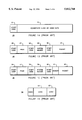
- FIGS. 1a-1c are block diagrams illustrating conventional elementary, systems and program bitstream profiles.
- FIG. 1d is a block diagram illustrating a conventional PES packet.
- FIG. 2 is a schematic diagram illustrating a preferred embodiment of the programmable systems layer parser in accordance with the present invention.
- FIGS. 3a-b are flow charts illustrating parser mode determination in accordance with the present invention.
- FIG. 4 is a flow chart illustrating parser operation in the elementary video mode in accordance with the present invention.
- FIG. 5 is a flow chart illustrating parser operation in the systems/program mode in accordance with the present invention.
- an elementary MPEG stream profile is shown to include start code 21 and data 22 portions.
- the start code 21 is typically 32 total bits and includes a twenty four 24 bit start code prefix (usually 23 zeroes followed by a 1) followed by an 8 bit stream identifier (in hexadecimal, 0000 01xx, where xx is the identifier).
- Elementary mode bitstreams typically include raw audio or video data which may be directly provided to a decoder or intermediately stored in a buffer and, thus, do not require systems layer parsing.
- audio and video data are parsed into separate buffers for decoding.
- a simplified MPEG-1 systems stream profile 25 is shown to include a pack layer 27, system header layer 29, packet layer 31 and corresponding start code portions 26, 28, 30.
- the pack layer 27 and system header layer 29 have a length which is predetermined by MPEG syntax. These layers 27, 29 are identified by start codes 26, 28, and provide, for example, bitstream decoding and synchronization information.
- the data in the packet layer 31 may be elementary audio or video, private MPEG data, or stuffing (garbage data) as defined by the start code stream identifier.
- the length of the packet layer 31 is not predetermined by syntax standards.
- the packet layer length, and other information is provided within the bitstream in a predetermined location (usually immediately following the start code). Parsing is more complicated than in the elementary mode since the various layers, such as the system header and the packet, may each be parsed into separate buffers and, moreover, since the length of the packet layer 31 may not be predetermined.
- an MPEG-2 Program bitstream 35 is shown to include a pack layer 37, system header layer 39, packet layer 42 and corresponding start code 36, 38, 40 portions.
- This stream profile is similar to the systems stream profile 25 except for its provision of a separate header 41.
- the bitstream 25 includes information such as the length of the header 41 and the packet layer 42. Neither the length of the header 41 or the packet layer 42 are predetermined by MPEG syntax, further complicating parsing.
- a transport decoder which typically outputs PES packets one byte at a time.
- the PES packets which may comprise audio and video data without a predetermined order, may be input to the parser.
- the bitstream is divided into portions 51, 52, 53 with non-predetermined lengths. Specifically, audio 51, 53 and video 52 packet portions of one or more bytes are multiplexed for PES transmission to the parser by the transport decoder.
- the input data organizer 201 preferably includes two serial to parallel converters 202, 204, a serial to parallel converter controller 214 and a multiplexer 220.
- the two serial to parallel converters 202, 204 for audio 204 and video 202 contexts each include a serial data input 206 (shown as a single, shared input port which accommodates multiple contexts), a control input 210 and a data byte output 212.
- the serial to parallel controller 214 is coupled 210 to send and receive control signals to and from the converters 202, 204 and the outputs 212 of the converters 202, 204 are input 212 to a multiplexer 220 which also includes a parallel port input 208 (also shown as a single, shared input), a serial/parallel mode control input 218 and a data output 222 which serves as the input data organizer 201 output.
- the data management buffer is a first-in-first-out buffer or register (“data FIFO") 224 which receives data bytes from the multiplexer output 222 and includes a control input 234 and a data output 236.
- the signals for the control input 234 are supplied by a data FIFO controller 238 which is coupled to the serial to parallel converter controller 214 and the microprogram controller 290.
- Each word in the data FIFO 224 includes a preselected number of data bits, preferably 8, and three status flags-AV 228, Sync 230 and Error 232.
- the data FIFO 224 output 236 and mask data 244 are input to a data mask 242 which provides data 248 to a multiplexer 250 along with immediate data 246 from microcode ROM 294 to provide a data output 252 to the system bus 254.
- Mask and immediate data as well as control signals for controlling the data mask 242 and multiplexer 250 are provided by the microprogram controller 290.
- the register file includes dual register sets to handle instantaneous context switching between the audio and video ports.
- Each register set is coupled to the bus 254 and comprises interrupt vector registers (not shown), counters 258, 260, 264, 266 and intermediate data buffers 270, 272, 278, 280.
- the register file includes corresponding audio and video context packet header counters 260, 258, packet length counters 266, 264, bottom of channel (“BOC") header data buffers 272, 270 and BOC packet data buffers 280, 278.
- Each of the register sets is coupled 262, 268, 274, 282 to the data bus. Additionally, the BOC header data buffers 278, 280 and the BOC packet data buffers 270, 272 output 284, 276 to a 4 ⁇ 1 multiplexer 285 which selects data 286 for a BOC FIFO (not shown).
- the logical unit is conventional and includes a comparator 287 with inputs 288, 289 connected to the bus 254 and the microprogram controller 290 with an equal output 291 which provides signals to the controller 290.
- the microprogram controller 290 preferably includes an instruction decoder 293 which includes logic to decode and execute instructions; a read only memory (ROM) 294 for storing microcode instructions, masking data and other information; and a plurality of program counters 296, 297 for processing data in dual contexts.
- the microprogram controller 290 is in communication with various elements including the serial to parallel converters 202, 204, the data FIFO 224, the register file and the logical unit 287 through a system bus 254.
- the controller 290 processes data in byte wise fashion at the direction of programmable instructions stored in the microcode portion of ROM 294.
- serial/parallel mode bit 218 is set to control the multiplexer 220 to provide data bytes to the data FIFO 224 from either the serial to parallel converters 202, 204 or a parallel port connected to the parallel input 208.
- Data may be provided to the parser 200 through audio and video ports.
- the data is supplied through a shared port with two valid (audio and video) and two request signals, although a variety of arrangements, including two separate ports, may be implemented.
- the AV bit 228 is set dependent upon the data input port. For example, if the audio valid signal is set for incoming data, then the AV bit in the data FIFO 224 is set as audio (0 or 1, as selected). Likewise, if subsequent data is transferred on video valid, then the AV bit 228 associated with such bytes is set as video.
- AV bit 228 merely identifies the port through which the data is provided, rather than the type of data provided. Association of the AV bit 228 to the data bytes in the data FIFO 224 provides an ongoing data context record which may be used by the controller 290 to segregate and separately process such data.
- Serial input data 206 is provided to the serial to parallel converters 202, 204 which convert the serial bitstream into parallel bytes of data and supply data bytes for each context to the multiplexer 220 for selective input to the data FIFO 224.
- the converters 202, 204 may be prompted by the controller 290 to seek start codes in the incoming bitstream.
- Each serial to parallel converter 202, 204 is arranged to detect an MPEG start code comprising twenty three zeroes followed by a one and a start code identifier.
- a state machine is used which detects start code prefixes by finding twenty three consecutive zeroes followed by a one. As logical zeroes are detected in the bitstream, the state machine progresses from an initial, or first state through a twenty third state. If a logical one is detected prior to the detection of twenty three consecutive zeroes, the state machine reverts back to the initial state to seek another string of zeroes.
- the state machine remains in the twenty third state while zeroes continue to be detected in the bitstream and, upon the detection of a one in the bitstream, a start code is detected.
- the start code identifier byte which typically follows the string of 23 zeroes and a one is passed to the data FIFO 224.
- the sync flag 230 is set (e.g. to logical one) in association with the identifier byte so that the parser 200 can process the byte as an identifier byte and, similarly, identify the data which follows it.
- the serial to parallel converters 202, 204 continue to convert the serial bitstream (for each context) into parallel bytes for processing.
- the sync flag 230 remains or is set to zero in association with such bytes. Since the sync flag 230 may be monitored for each processed byte, the parser 200 may be arranged to continuously process the byte aligned data while the sync flag remains at a given state (such as at zero for byte aligned data following a detected start code).
- the converters 202, 204 may also be prompted to seek unexpected start codes in the bitstream.
- An unexpected start code is detected by the state machine in the same fashion that a sought start code is detected as explained above and, similarly, the sync flag 230 may be set upon the detection of a start code.
- An unexpected start code could indicate a synchronization error.
- the controller 290 may prompt the serial to parallel converters 202, 204 to provide notification of an unexpected, non-byte aligned start code, or, in other words, a sync error, so that the controller 290 may interrupt processing of the synchronized byte aligned data.
- the controller 290 is arranged to continuously process byte aligned data while the sync flag 230 is at logical zero and branch to a synchronization error handling routine if an unexpected start code is indicated by the sync flag 230 at logical one.
- synchronization errors such as controller detected sync errors, which may be monitored using the sync flag 230.
- start codes in the byte aligned data may be sought and detected by the controller 290 by using programmed code which facilitates the comparison of data bytes to predetermined data (e.g. to detect twenty three zeroes followed by a one and a start code identifier, a string of bytes such as 00, 00, 01, xx could be detected).
- an Error flag 232 may be associated with bytes in the data FIFO 224 to indicate an error.
- the error flag may be set by the source of data through an external error pin (not shown) where the data source detected and issued an error signal associated to the transmitted data.
- the microprogram controller 290 may detect a syntax error in the bitstream and set the error flag, 232 through the FIFO controller 238.
- the controller 290 may detect such a syntax error and, accordingly, set the error flag 232 in association with the defective byte or bytes.
- the affected program counter 296, 297 will be forced to the interrupt vector provided that the interrupt is not masked.
- Interrupt handling is preferably provided by the dual interrupt vector registers (not shown). The interrupt is maskable with a mask bit that is set by the microprogram controller 290 and is programmable to handle multiple interrupt routines.
- the data is sequentially loaded in bytes from the multiplexer 220 to the data FIFO 224 and, since each data word preferably includes eight bits of data and three status bits, the three flags 228, 230, 232 remain associated with the data bytes to facilitate processing by the microprogram controller 290.
- the data FIFO 224 sequentially provides data bytes for parsing to the system bus 254 at the direction of the controller 290.
- the register file is connected to the system bus 254 to receive bytes which pass through the data FIFO 224 or, alternatively, data for processing such bytes.
- the packet header counters 258, 260 maintain the number of data bytes contained in a processed packet header and work with the BOC header data buffers 270, 272 to parse packet header data.
- the packet length counters 264, 266 maintain the amount of packet data to be segregated into the BOC packet data buffers 278, 280. For example, the packet length may be indicated as 64 Kbytes, and that value may be loaded into the appropriate packet length counter 264, 266.
- Subsequent packet data bytes would be sequentially loaded into the appropriate packet data buffer 278, 280, and, as such bytes are loaded, the packet length counter 264, 266 may be decremented to monitor the amount of remaining bytes to be loaded.
- the data temporarily stored in the data buffers 270, 272, 278, 280 is provided to multiplexer 285 which directs it to another buffer, preferably a bottom of channel (BOC) FIFO (not shown) which, in turn, provides the data to a destination buffer such as a DRAM channel (not shown) arranged per MPEG standards.
- BOC bottom of channel
- the various buffers facilitate a steady flow of data to the DRAM channel to prevent it from emptying (and causing a gap in decoding)
- This architecture in conjunction with the custom parsing instruction set and with an appropriately size and service rate for the BOC, provides a minimum data transfer rate of approximately 40 megabits per second.
- the register file also includes dual sets which, in conjunction with the dual program counters 296, 297, facilitate instantaneous context switching between data transferred through the audio and video ports. Specifically, where the bytes of data are identified as video by the AV flag 228 in the data FIFO 224, they are processed using the video program counter 296 and video register set 258, 264, 270, 278. The information for a first context may be retained in these registers while another context, or an interrupt handling routine, is processed.
- the logical unit 287 is arranged to compare data and, on a positive comparison, output an equal flag 291 which feeds back to the microprogram controller 290.
- the equal output may be used to identify bytes from the data FIFO 224 or other data. For example, if a data byte is recognized as a start code, the controller 290 may pass the start code identifier byte to the logical unit 287 to compare it to immediate data 246 from the microcode ROM 294 for identification.
- the microprogram controller 290 manages comparison, flow and storage of data bytes from the data FIFO 224 by issuing control signals to and receiving signals from the logical unit 287, the register file, the serial to parallel converters 202, 204 and the Data FIFO 224.
- the controller 290 incorporates various operations to manage the flow of byte aligned data through the data FIFO 224. Specifically, the controller 290 may mask the present byte by supplying data and appropriate controls to the data mask 242, pass the byte to the logical unit 287 for identification or comparison to other data, load the byte into a buffer for that type of data, or load the byte into an appropriate register in the register file. For example, elementary video data may be transferred into a video data buffer such as a DRAM channel, or, where an MPEG program bitstream is processed, bytes of packet 31, 42 data may be loaded into a BOC packet data buffer.
- a video data buffer such as a DRAM channel
- an MPEG program bitstream is processed
- the controller 290 in conjunction with the register file, is arranged to process layers of data with various predetermined and non-predetermined lengths. If the identified bitstream has a fixed, predetermined length (e.g. as defined by syntax), then the number of bytes which must be sent to the appropriate buffer may be provided in the program code in microcode ROM 294. However, if the bitstream length is not predetermined, then the number of bytes which must be sent to a buffer is preferably determined from information in the bitstream and loaded into a counter whereby the extent of data loading into an intermediate buffer can be tracked. For example, if a bitstream start code is recognized as an MPEG-1 systems stream packet layer 31, then the length of the bitstream is found, according to syntax, in the packet layer header.
- a bitstream start code is recognized as an MPEG-1 systems stream packet layer 31
- the length of the bitstream is found, according to syntax, in the packet layer header.
- the length can be converted into the number of bytes which must be loaded from the data FIFO 224 for parsing into the packet layer buffer and this number is loaded into a packet length counter 264, 266 for tracking. If packet layer parsing is ongoing and the present context is interrupted, for example, by byte aligned data from the other context or an interrupt, then the counter will maintain the number of bytes which must still be parsed.
- a microprogram controller 290 is used for parsing, a custom instruction set may be designed for each application using microprogramming techniques.
- An instruction set and corresponding microprogram for a common application may be designed and provided in microcode ROM 294. This allows for flexible parser design and easy debugging and variation from application to application. Additionally, since only necessary instructions are implemented, the parser is extremely efficient. Finally, a parser for a common application may be designed and provided very inexpensively.
- the instruction set facilitates comparison of data for identification and other purposes, storage of data and branching to predetermined routines under defined conditions and control of the flow of data.
- These basic operations allow the parser to be programmed to operate as specified above and, more specifically, to process MPEG data as set forth below.
- instructions may be provided which facilitate comparison of start codes to known data to identify bitstreams, storing data in locations appropriate to the identified data type, branching to routines including error handling routines, and continuously storing data while it is synchronized and no error has occurred.
- the controller 290 initially checks 305 the AV status bit 228 to determine the present context. This is preferably done by masking the data byte and comparing the masked data to predetermined (immediate) data using the logical unit 287 sets the equal output 291 upon a positive identification. Where the audio context is indicated, the controller 290 branches 310 to an audio mode determination routine 313 wherein it prompts the logical unit 287 to set the equal output 291 if the PES Stream mode bit (not shown) is set 315 and branches 320 on equal to the PES Audio Data operational mode 325.
- the Systems/Program Stream Status bit is checked 330 to determine whether to branch to that operational mode 340. Similarly, the controller determines whether the Elementary Stream Status bit is set 345 to branch 350 to that mode 355 or, by default, to the Systems/Program Stream protocol 340.
- parser 200 operation for mode determination 360 where the AV status bit 228 indicates the video context is shown.
- the controller 290 initially determines whether the PES Stream mode bit is set 365, branches 370 on equal to the PES Video Stream protocol 375 and otherwise determines whether the Elementary Stream mode bit is set 380 to branch 385 to that protocol 390 or, alternatively, to the discard video data protocol 395.
- parser 200 operation in the elementary video 390 operational mode is shown.
- the controller 290 initially determines whether parallel or serial data are incoming by checking that mode bit 405 and branches 410 to the appropriate data input mode.
- a start code may be detected 413 by using the logical unit 287 in a series of comparisons to detect twenty three zeroes followed by a one (the bytes are assumed to be aligned in the parallel mode) as described above.
- bytes are continuously loaded 415 from the data FIFO 224 to a destination buffer such as a video data buffer (not shown) while they remain synchronized and no data error 425 has been issued by the source of data.
- a set error bit 425 may initiate any desired error handling routines, such as one which indicates 430 the error in the video data buffer, removes 435 a preselected number of bytes from the data FIFO 224 and returns to data loading 415.
- the controller enters a stall mode, or, where the controller is reset, seeks a new start code.
- the controller 290 issues 440 a synchronization command prompting the serial to parallel converters 202, 204 to seek start codes in the incoming bitstream and indicate receipt of the start code by setting the sync flag associated with the start code bytes, or, at least, the start code identifier byte.
- the controller monitors 445 the sync bit and discards successive data bytes 485 or stores 450 the start code prefix and stream identifier in the video data buffer dependent upon the status of the sync bit 450.
- the contents of the data FIFO 224 are continuously loaded 460 into the video data buffer while the data bytes are synchronized 490 and no error has been issued 470 by the source of data or detected 470 by the controller 290 such that the sync flag 230 is set.
- Various routines for handling sync and source issued errors may be provided, but preferably, if the source issues an error, data loading 460 proceeds after the error is indicated in the video data buffer 473 and a preselected number of bytes are removed from 480 the data FIFO 224. If a sync error occurs 490, a byte is removed 485 from the data FIFO 224 and the controller 290 seeks the next start code 440 and if both errors occur 470, 475, the controller 290 seeks 440 the next start code in the incoming bitstream after indicating 473 the error in the video data buffer and removal 495 of a preselected number of bytes from the Data FIFO 224.
- the parser 200 In the MPEG Systems/Program stream mode 340, the parser 200 expects MPEG-1 System stream syntax or, alternatively, MPEG-2 Program stream syntax. Audio and Video data are assumed to be time multiplexed into one data stream and strobed into the parser on the audio port. The video port data is ignored when operating in this mode, but the data type is distinguished within the bitstream.
- this mode 340 includes bitstream identification through examination 510 of the start code identifier.
- the parser 200 identifies 510 the bitstream by comparing the identifier to known data stored in memory 294 and, upon a positive identification, branches to the appropriate routine. If the identifier indicates that the bitstream to follow has a fixed, predetermined length such as the pack 27, 37 and system header 29, 39 layers of Systems 25 or Program 30 bitstreams, the controller 290 branches 515 to routines for loading 520 the known number of bytes from the data FIFO 224 to a destination data buffer (not shown) appropriate for the identified data.
- the examination 510 of the start code reveals a variable or undetermined length bitstream such as a packet layer 31, 42, the controller branches to routines to handle such layers.
- Identification 525 of an MPEG-1 systems stream packet layer 31 prompts loading 530 of the packet length counter 266 according to the information in the packet header followed by sequential byte loading from the data FIFO 224 to the BOC packet data buffer 280.
- the packet length counter 266 is decremented 540 as bytes are loaded until it equals one 575 whereupon the last byte in the packet layer 31 is processed 600 specially. For example, the last byte may be loaded into the buffer and then the next start code may be sought 602.
- An MPEG-2 Program Stream packet layer must be parsed differently since the bitstreams for both the header 41 and packet 42 have lengths which are not predetermined by the syntax, but, rather, are defined within each individual bitstream.
- Identification 550 of a program stream 30 packet layer 42 prompts the controller 290 to load 555, 560 the packet header counter 260 and the packet length counter 266 according to the information provided in the bitstream 25.
- the parser 200 at the instruction of the controller 290, then loads the BOC header data buffer 272 with byte-aligned header data from the Data FIFO 224 and intermediately decrements 540 the packet header counter 260 until it reaches one 575 whereupon the last byte in the header 36 is loaded 580.
- the BOC Packet data buffer 280 is loaded 585 from the data FIFO 224 based upon the packet length counter until it reaches one 595 whereupon the last data byte in the packet layer 42 is processed 600 specially.
- the last byte is loaded into its appropriate buffer and then and the next start code is sought.
- the parser 200 In the PES stream mode, the parser 200 expects to receive audio PES packets on the audio port and video PES packets on the video port. Audio packets strobed through the video port, and vice versa, are discarded.
- the parser is able to context switch between audio and video port data and assembles those portions of the packet layer that are transmitted to the parser.
- the basic operation of the parser is similar to that set forth for the elementary and systems/program modes. Here, however, portions of audio and video packets are transmitted to the parser as shown in FIG. 1d.
- the context switching capabilities of the parser 200 allow it to process one context and to hold the status of that context when another context is identified. Identification is immediate, as each data byte includes an AV status.
- the controller 290 may be programmed according to the particulars of the PES transfer protocol.
- any multimedia data with a syntax which defines layers of predetermined and/or non-predetermined lengths including those other than MPEG types may be processed by the parser 200.
- dual registers in addition to the packet header counters 258, 260, packet length counters 264, 266, and header and packet data buffers 270, 272, 278, 280 may be provided where additional data portions require intermediate storage.
Abstract
Description
Claims (13)
Priority Applications (1)
| Application Number | Priority Date | Filing Date | Title |
|---|---|---|---|
| US08/670,090 US5812760A (en) | 1996-06-25 | 1996-06-25 | Programmable byte wise MPEG systems layer parser |
Applications Claiming Priority (1)
| Application Number | Priority Date | Filing Date | Title |
|---|---|---|---|
| US08/670,090 US5812760A (en) | 1996-06-25 | 1996-06-25 | Programmable byte wise MPEG systems layer parser |
Publications (1)
| Publication Number | Publication Date |
|---|---|
| US5812760A true US5812760A (en) | 1998-09-22 |
Family
ID=24688948
Family Applications (1)
| Application Number | Title | Priority Date | Filing Date |
|---|---|---|---|
| US08/670,090 Expired - Lifetime US5812760A (en) | 1996-06-25 | 1996-06-25 | Programmable byte wise MPEG systems layer parser |
Country Status (1)
| Country | Link |
|---|---|
| US (1) | US5812760A (en) |
Cited By (39)
| Publication number | Priority date | Publication date | Assignee | Title |
|---|---|---|---|---|
| US6041406A (en) * | 1997-04-08 | 2000-03-21 | Advanced Micro Devices, Inc. | Parallel and serial debug port on a processor |
| US6142683A (en) * | 1997-04-08 | 2000-11-07 | Advanced Micro Devices, Inc. | Debug interface including data steering between a processor, an input/output port, and a trace logic |
| EP1051041A1 (en) * | 1999-05-07 | 2000-11-08 | Deutsche Thomson-Brandt Gmbh | Method for searching start codes |
| US6148381A (en) * | 1997-04-08 | 2000-11-14 | Advanced Micro Devices, Inc. | Single-port trace buffer architecture with overflow reduction |
| EP1056297A2 (en) * | 1999-05-24 | 2000-11-29 | Agilent Technologies Inc. | Multimedia decoder with error detection |
| US6175914B1 (en) * | 1997-12-17 | 2001-01-16 | Advanced Micro Devices, Inc. | Processor including a combined parallel debug and trace port and a serial port |
| US6226291B1 (en) * | 1996-11-01 | 2001-05-01 | Texas Instruments Incorporated | Transport stream packet parser system |
| US20010004768A1 (en) * | 1998-09-28 | 2001-06-21 | Hodge Winston W. Hodge Winston W. | Highly integrated computer controlled digital head end |
| US20010005908A1 (en) * | 1998-09-28 | 2001-06-28 | Hodge Winston W. | Method for buffering video, data and voice signals using a common shared bus |
| US6263019B1 (en) * | 1998-10-09 | 2001-07-17 | Matsushita Electric Industrial Co., Ltd. | Variable rate MPEG-2 video syntax processor |
| US20020056143A1 (en) * | 1998-09-28 | 2002-05-09 | Hodge Winston W. | Programmable broadband downstream module |
| US20020056125A1 (en) * | 1998-09-28 | 2002-05-09 | Hodge Winston W. | Multi-tier buffering system and method which combines video, data, and voice packets |
| US20020144279A1 (en) * | 2001-03-30 | 2002-10-03 | Guojun Zhou | Method and apparatus for providing custom television channels to viewers |
| US6502152B1 (en) * | 1999-03-08 | 2002-12-31 | Texas Instruments Incorporated | Dual interrupt vector mapping |
| US6522694B1 (en) * | 1998-10-09 | 2003-02-18 | Matsushita Electric Industrial Co., Ltd. | Programmable filter for removing stuffing bits from an MPEG-2 bit-stream |
| US20030106049A1 (en) * | 2001-11-30 | 2003-06-05 | Sun Microsystems, Inc. | Modular parser architecture |
| US6611524B2 (en) | 1999-06-30 | 2003-08-26 | Cisco Technology, Inc. | Programmable data packet parser |
| US6717620B1 (en) * | 1998-06-12 | 2004-04-06 | Ati Technologies, Inc. | Method and apparatus for decompressing compressed data |
| US6763390B1 (en) | 2000-01-24 | 2004-07-13 | Ati Technologies, Inc. | Method and system for receiving and framing packetized data |
| US6778533B1 (en) | 2000-01-24 | 2004-08-17 | Ati Technologies, Inc. | Method and system for accessing packetized elementary stream data |
| US20040165666A1 (en) * | 2002-11-26 | 2004-08-26 | Hiroaki Kubo | Format conversion circuit |
| US6785336B1 (en) * | 2000-01-24 | 2004-08-31 | Ati Technologies, Inc. | Method and system for retrieving adaptation field data associated with a transport packet |
| US20040174912A1 (en) * | 1999-05-01 | 2004-09-09 | Samsung Electronics Co., Ltd. | Multiplexing video decoding apparatus and method |
| EP1028593A3 (en) * | 1999-02-11 | 2005-01-26 | PacketVideo Corporation | Method and device for control and delivery of digitally compressed visual data in a heterogeneous communication network |
| US20050028047A1 (en) * | 2003-07-30 | 2005-02-03 | Dehai Kong | Method and circuit for command integrity checking (CIC) in a graphics controller |
| US20050060420A1 (en) * | 2003-09-11 | 2005-03-17 | Kovacevic Branko D. | System for decoding multimedia data and method thereof |
| US6885680B1 (en) | 2000-01-24 | 2005-04-26 | Ati International Srl | Method for synchronizing to a data stream |
| US20050105564A1 (en) * | 2001-03-07 | 2005-05-19 | General Instrument Corporation | Methods and apparatus for reconfiguring protocol data when reducing multiplexed data streams |
| US20050175106A1 (en) * | 2004-02-09 | 2005-08-11 | Ravindra Bidnur | Unified decoder architecture |
| US20050238010A1 (en) * | 2004-04-26 | 2005-10-27 | Rina Panigrahy | Programmable packet parsing processor |
| US6988238B1 (en) | 2000-01-24 | 2006-01-17 | Ati Technologies, Inc. | Method and system for handling errors and a system for receiving packet stream data |
| US20070009236A1 (en) * | 2000-11-06 | 2007-01-11 | Ati Technologies, Inc. | System for digital time shifting and method thereof |
| US7366961B1 (en) | 2000-01-24 | 2008-04-29 | Ati Technologies, Inc. | Method and system for handling errors |
| US20110116507A1 (en) * | 2009-11-16 | 2011-05-19 | Alon Pais | Iterative parsing and classification |
| US8284845B1 (en) | 2000-01-24 | 2012-10-09 | Ati Technologies Ulc | Method and system for handling data |
| USRE44466E1 (en) | 1995-12-07 | 2013-08-27 | Koninklijke Philips Electronics N.V. | Method and device for packaging audio samples of a non-PCM encoded audio bitstream into a sequence of frames |
| CN104904146A (en) * | 2013-01-04 | 2015-09-09 | 索尼公司 | JCTVC-L0226: VPS and VPS_EXTENSION updates |
| CN113228665A (en) * | 2018-10-31 | 2021-08-06 | 威诺瓦国际有限公司 | Method, device, computer program and computer-readable medium for processing configuration data |
| GB2596646B (en) * | 2018-10-31 | 2023-08-02 | V Nova Int Ltd | Methods, apparatuses, computer programs and computer-readable media for scalable image coding |
Citations (6)
| Publication number | Priority date | Publication date | Assignee | Title |
|---|---|---|---|---|
| US5526054A (en) * | 1995-03-27 | 1996-06-11 | International Business Machines Corporation | Apparatus for header generation |
| US5533021A (en) * | 1995-02-03 | 1996-07-02 | International Business Machines Corporation | Apparatus and method for segmentation and time synchronization of the transmission of multimedia data |
| US5561670A (en) * | 1994-05-13 | 1996-10-01 | Apple Computer, Inc. | Method and apparatus for operating a multicast system on an unreliable network |
| US5652749A (en) * | 1995-02-03 | 1997-07-29 | International Business Machines Corporation | Apparatus and method for segmentation and time synchronization of the transmission of a multiple program multimedia data stream |
| US5675829A (en) * | 1995-07-07 | 1997-10-07 | Sun Microsystems, Inc. | Method and apparatus for coordinating data transfer between hardware and software by comparing entry number of data to be transferred data to entry number of transferred data |
| US5689509A (en) * | 1995-07-07 | 1997-11-18 | Sun Microsystems, Inc. | Apparatus and method for packetizing and segmenting MPEG packets |
-
1996
- 1996-06-25 US US08/670,090 patent/US5812760A/en not_active Expired - Lifetime
Patent Citations (6)
| Publication number | Priority date | Publication date | Assignee | Title |
|---|---|---|---|---|
| US5561670A (en) * | 1994-05-13 | 1996-10-01 | Apple Computer, Inc. | Method and apparatus for operating a multicast system on an unreliable network |
| US5533021A (en) * | 1995-02-03 | 1996-07-02 | International Business Machines Corporation | Apparatus and method for segmentation and time synchronization of the transmission of multimedia data |
| US5652749A (en) * | 1995-02-03 | 1997-07-29 | International Business Machines Corporation | Apparatus and method for segmentation and time synchronization of the transmission of a multiple program multimedia data stream |
| US5526054A (en) * | 1995-03-27 | 1996-06-11 | International Business Machines Corporation | Apparatus for header generation |
| US5675829A (en) * | 1995-07-07 | 1997-10-07 | Sun Microsystems, Inc. | Method and apparatus for coordinating data transfer between hardware and software by comparing entry number of data to be transferred data to entry number of transferred data |
| US5689509A (en) * | 1995-07-07 | 1997-11-18 | Sun Microsystems, Inc. | Apparatus and method for packetizing and segmenting MPEG packets |
Non-Patent Citations (15)
| Title |
|---|
| Beriont, W., The Broadband Network Interface for Television, GTE Labs, Mass., IEEE Transaction on Consumer Electronics, vol. 38, No. 4, pp. 906 909, 4 Nov. 1992. * |
| Beriont, W., The Broadband Network Interface for Television, GTE Labs, Mass., IEEE Transaction on Consumer Electronics, vol. 38, No. 4, pp. 906-909, 4 Nov. 1992. |
| Galbi, A. et al., An MPEG 1 Audio/Video Decoder w/ Run Length Compressed Antialiased Video Overlays, IEEE Solid State Circuit Conference, 1995, pp. 286 287, 1995. * |
| Galbi, A. et al., An MPEG-1 Audio/Video Decoder w/ Run-Length Compressed Antialiased Video Overlays, IEEE Solid State Circuit Conference, 1995, pp. 286-287, 1995. |
| Keck, Wolfram, A Method for Robust Decoding of Erroreous MPEG 2 Bitstreams, University of Stuttgart, Germany, IEEE vol. 42, No. 3 Transaction on Consumer Electronics, pp. 411 421, 10 Jun. 1996. * |
| Keck, Wolfram, A Method for Robust Decoding of Erroreous MPEG-2 Bitstreams, University of Stuttgart, Germany, IEEE vol. 42, No. 3 Transaction on Consumer Electronics, pp. 411-421, 10 Jun. 1996. |
| La Porta, T. et al., Performance Analysis of MSP:Feature Rich High Speed Transport Protocol, IEEE Transaction on Networking. vol. 1, No. 6, pp. 740 753, 6 Dec. 1993. * |
| La Porta, T. et al., Performance Analysis of MSP:Feature-Rich High Speed Transport Protocol, IEEE Transaction on Networking. vol. 1, No. 6, pp. 740-753, 6 Dec. 1993. |
| Pasquale, Joseph et al., Real time dissemination of Continuous Media in Packet Switched Networks, Compcon Sir 93, IEEE Computer Society Int l Conference, pp. 47 48, 1993. * |
| Pasquale, Joseph et al., Real-time dissemination of Continuous Media in Packet-Switched Networks, Compcon Sir 93, IEEE Computer Society Int'l Conference, pp. 47-48, 1993. |
| T.H. Doi et al., A PC Based MPEG Compressed Data Decoder, Nanyang University, Singapore, IEEE Transaction on Consumer Electronics, vol. 41, Issue No. 4, 22 Aug. 1995. * |
| T.H. Doi et al., A PC-Based MPEG Compressed Data Decoder, Nanyang University, Singapore, IEEE Transaction on Consumer Electronics, vol. 41, Issue No. 4, 22 Aug. 1995. |
| Thomas La Porta, et. al., The Multistream Protocol: A Highly Flexible High Speed Transport Protocol, Journal on Selected Areas in Communication, vol. 11, No. 4, IEEE, 4 May 1993. * |
| V. Bhaskaran, Media Processing in the Compressed Domain, H P Labs, Palo Alto, CA., Compcon 96 IEEE Computer Society Int l pp. 204 209, 1996. * |
| V. Bhaskaran, Media Processing in the Compressed Domain, H P Labs, Palo Alto, CA., Compcon 96 IEEE Computer Society Int'l pp. 204-209, 1996. |
Cited By (58)
| Publication number | Priority date | Publication date | Assignee | Title |
|---|---|---|---|---|
| USRE44955E1 (en) | 1995-12-07 | 2014-06-17 | Koninklijke Philips N.V. | Method and device for packaging audio samples of a non-PCM encoded audio bitstream into a sequence of frames |
| USRE44466E1 (en) | 1995-12-07 | 2013-08-27 | Koninklijke Philips Electronics N.V. | Method and device for packaging audio samples of a non-PCM encoded audio bitstream into a sequence of frames |
| US6226291B1 (en) * | 1996-11-01 | 2001-05-01 | Texas Instruments Incorporated | Transport stream packet parser system |
| US6142683A (en) * | 1997-04-08 | 2000-11-07 | Advanced Micro Devices, Inc. | Debug interface including data steering between a processor, an input/output port, and a trace logic |
| US6041406A (en) * | 1997-04-08 | 2000-03-21 | Advanced Micro Devices, Inc. | Parallel and serial debug port on a processor |
| US6148381A (en) * | 1997-04-08 | 2000-11-14 | Advanced Micro Devices, Inc. | Single-port trace buffer architecture with overflow reduction |
| US6175914B1 (en) * | 1997-12-17 | 2001-01-16 | Advanced Micro Devices, Inc. | Processor including a combined parallel debug and trace port and a serial port |
| US6717620B1 (en) * | 1998-06-12 | 2004-04-06 | Ati Technologies, Inc. | Method and apparatus for decompressing compressed data |
| US20010005908A1 (en) * | 1998-09-28 | 2001-06-28 | Hodge Winston W. | Method for buffering video, data and voice signals using a common shared bus |
| US20020056143A1 (en) * | 1998-09-28 | 2002-05-09 | Hodge Winston W. | Programmable broadband downstream module |
| US20020056125A1 (en) * | 1998-09-28 | 2002-05-09 | Hodge Winston W. | Multi-tier buffering system and method which combines video, data, and voice packets |
| US20010004768A1 (en) * | 1998-09-28 | 2001-06-21 | Hodge Winston W. Hodge Winston W. | Highly integrated computer controlled digital head end |
| US6263019B1 (en) * | 1998-10-09 | 2001-07-17 | Matsushita Electric Industrial Co., Ltd. | Variable rate MPEG-2 video syntax processor |
| US6522694B1 (en) * | 1998-10-09 | 2003-02-18 | Matsushita Electric Industrial Co., Ltd. | Programmable filter for removing stuffing bits from an MPEG-2 bit-stream |
| EP1028593A3 (en) * | 1999-02-11 | 2005-01-26 | PacketVideo Corporation | Method and device for control and delivery of digitally compressed visual data in a heterogeneous communication network |
| US6502152B1 (en) * | 1999-03-08 | 2002-12-31 | Texas Instruments Incorporated | Dual interrupt vector mapping |
| US7421026B2 (en) * | 1999-05-01 | 2008-09-02 | Samsung Electronics Co., Ltd. | Multiplexing video decoding apparatus and method |
| US20040174912A1 (en) * | 1999-05-01 | 2004-09-09 | Samsung Electronics Co., Ltd. | Multiplexing video decoding apparatus and method |
| EP1051041A1 (en) * | 1999-05-07 | 2000-11-08 | Deutsche Thomson-Brandt Gmbh | Method for searching start codes |
| EP1056297A2 (en) * | 1999-05-24 | 2000-11-29 | Agilent Technologies Inc. | Multimedia decoder with error detection |
| EP1056297A3 (en) * | 1999-05-24 | 2002-10-02 | Agilent Technologies, Inc. (a Delaware corporation) | Multimedia decoder with error detection |
| US6611524B2 (en) | 1999-06-30 | 2003-08-26 | Cisco Technology, Inc. | Programmable data packet parser |
| US8284845B1 (en) | 2000-01-24 | 2012-10-09 | Ati Technologies Ulc | Method and system for handling data |
| US6785336B1 (en) * | 2000-01-24 | 2004-08-31 | Ati Technologies, Inc. | Method and system for retrieving adaptation field data associated with a transport packet |
| US20050021813A1 (en) * | 2000-01-24 | 2005-01-27 | Ati Technologies, Inc. | Method and system for receiving and framing packetized data |
| US6778533B1 (en) | 2000-01-24 | 2004-08-17 | Ati Technologies, Inc. | Method and system for accessing packetized elementary stream data |
| US6885680B1 (en) | 2000-01-24 | 2005-04-26 | Ati International Srl | Method for synchronizing to a data stream |
| US6763390B1 (en) | 2000-01-24 | 2004-07-13 | Ati Technologies, Inc. | Method and system for receiving and framing packetized data |
| US7376692B2 (en) | 2000-01-24 | 2008-05-20 | Ati Technologies, Inc. | Method and system for receiving and framing packetized data |
| US7366961B1 (en) | 2000-01-24 | 2008-04-29 | Ati Technologies, Inc. | Method and system for handling errors |
| US6988238B1 (en) | 2000-01-24 | 2006-01-17 | Ati Technologies, Inc. | Method and system for handling errors and a system for receiving packet stream data |
| US20070009236A1 (en) * | 2000-11-06 | 2007-01-11 | Ati Technologies, Inc. | System for digital time shifting and method thereof |
| US8260109B2 (en) | 2000-11-06 | 2012-09-04 | Ati Technologies Ulc | System for digital time shifting and method thereof |
| USRE47054E1 (en) | 2000-11-06 | 2018-09-18 | Ati Technologies Ulc | System for digital time shifting and method thereof |
| US20050105564A1 (en) * | 2001-03-07 | 2005-05-19 | General Instrument Corporation | Methods and apparatus for reconfiguring protocol data when reducing multiplexed data streams |
| US7653089B2 (en) * | 2001-03-07 | 2010-01-26 | General Instrument Corporation | Methods and apparatus for reconfiguring protocol data when reducing multiplexed data streams |
| US20020144279A1 (en) * | 2001-03-30 | 2002-10-03 | Guojun Zhou | Method and apparatus for providing custom television channels to viewers |
| US7089541B2 (en) * | 2001-11-30 | 2006-08-08 | Sun Microsystems, Inc. | Modular parser architecture with mini parsers |
| US20030106049A1 (en) * | 2001-11-30 | 2003-06-05 | Sun Microsystems, Inc. | Modular parser architecture |
| US20040165666A1 (en) * | 2002-11-26 | 2004-08-26 | Hiroaki Kubo | Format conversion circuit |
| US8014452B2 (en) * | 2002-11-26 | 2011-09-06 | International Business Machines Corporation | Format conversion circuit |
| US7197669B2 (en) * | 2003-07-30 | 2007-03-27 | Via Technologies, Inc. | Method and circuit for command integrity checking (CIC) in a graphics controller |
| US20050028047A1 (en) * | 2003-07-30 | 2005-02-03 | Dehai Kong | Method and circuit for command integrity checking (CIC) in a graphics controller |
| US20050060420A1 (en) * | 2003-09-11 | 2005-03-17 | Kovacevic Branko D. | System for decoding multimedia data and method thereof |
| EP1562383A3 (en) * | 2004-02-09 | 2005-08-17 | Broadcom Corporation | Multistandard video decoder |
| US20050175106A1 (en) * | 2004-02-09 | 2005-08-11 | Ravindra Bidnur | Unified decoder architecture |
| US7720294B2 (en) | 2004-02-09 | 2010-05-18 | Broadcom Corporation | Unified decoder architecture |
| US7586851B2 (en) * | 2004-04-26 | 2009-09-08 | Cisco Technology, Inc. | Programmable packet parsing processor |
| US20050238010A1 (en) * | 2004-04-26 | 2005-10-27 | Rina Panigrahy | Programmable packet parsing processor |
| US8599859B2 (en) * | 2009-11-16 | 2013-12-03 | Marvell World Trade Ltd. | Iterative parsing and classification |
| US20110116507A1 (en) * | 2009-11-16 | 2011-05-19 | Alon Pais | Iterative parsing and classification |
| CN104904146A (en) * | 2013-01-04 | 2015-09-09 | 索尼公司 | JCTVC-L0226: VPS and VPS_EXTENSION updates |
| CN104904146B (en) * | 2013-01-04 | 2018-03-13 | 索尼公司 | JCTVC‑L0226:VPS and VPS_EXTENSION renewals |
| CN113228665A (en) * | 2018-10-31 | 2021-08-06 | 威诺瓦国际有限公司 | Method, device, computer program and computer-readable medium for processing configuration data |
| US20210377550A1 (en) * | 2018-10-31 | 2021-12-02 | V-Nova International Limited | Methods, apparatuses, computer programs and computer-readable media for processing configuration data |
| GB2596646B (en) * | 2018-10-31 | 2023-08-02 | V Nova Int Ltd | Methods, apparatuses, computer programs and computer-readable media for scalable image coding |
| US11750825B2 (en) * | 2018-10-31 | 2023-09-05 | V-Nova International Limited | Methods, apparatuses, computer programs and computer-readable media for processing configuration data |
| US20240048738A1 (en) * | 2018-10-31 | 2024-02-08 | V-Nova International Limited | Methods, apparatuses, computer programs and computer-readable media for processing configuration data |
Similar Documents
| Publication | Publication Date | Title |
|---|---|---|
| US5812760A (en) | Programmable byte wise MPEG systems layer parser | |
| US5821886A (en) | Variable length code detection in a signal processing system | |
| JP3641336B2 (en) | Data separator | |
| JP3464264B2 (en) | Data packet transmission / reception method | |
| US6654423B2 (en) | PID/section filter in digital television system | |
| EP0840518B1 (en) | MPEG transport stream parser system and method | |
| KR100441822B1 (en) | Compressed Video Signal Transmitter | |
| US5898897A (en) | Bit stream signal feature detection in a signal processing system | |
| US20080288663A1 (en) | Method and system for handling errors | |
| KR19980073528A (en) | MPEG System Decoder | |
| US5812976A (en) | System and method for interfacing a transport decoder to a bitrate-constrained audio recorder | |
| US4974223A (en) | Parallel architecture for high speed flag detection and packet identification | |
| US6278838B1 (en) | Peak-ahead FIFO for DVD system stream parsing | |
| JP3693702B2 (en) | Media error code generator for reverse transport processor | |
| US6512775B1 (en) | Method and apparatus for a programmable bitstream parser for audiovisual and generic decoding systems | |
| EP0933949B1 (en) | Transmitting system, transmitting apparatus, recording and reproducing apparatus | |
| EP0948214A2 (en) | Method and apparatus for detecting a start code in a bitstream | |
| US5675654A (en) | System and method for interfacing a transport decoder to a national renewable security systems (NRSS) smart card | |
| US7697537B2 (en) | System and method for using generic comparators with firmware interface to assist video/audio decoders in achieving frame sync | |
| US7590117B2 (en) | Multichannel processor | |
| US6961338B2 (en) | Demultiplexer for handling different multiplexed data formats | |
| US20040264502A1 (en) | Data alignment of the packetized elementary streams in the coded data buffer for dual decode | |
| USRE41179E1 (en) | Device for extracting parameters for decoding a video data flow coded according to an MPEG standard | |
| JP3844854B2 (en) | System decoder and MPEG2 decoding device | |
| US20040190631A1 (en) | PES data processing |
Legal Events
| Date | Code | Title | Description |
|---|---|---|---|
| AS | Assignment |
Owner name: LSI LOGIC CORPORATION, CALIFORNIA Free format text: ASSIGNMENT OF ASSIGNORS INTEREST;ASSIGNORS:MENDENHALL, TODD;NEUMAN, DARREN;GOZU, MANABU;REEL/FRAME:008056/0609 Effective date: 19960624 |
|
| STCF | Information on status: patent grant |
Free format text: PATENTED CASE |
|
| FEPP | Fee payment procedure |
Free format text: PAYOR NUMBER ASSIGNED (ORIGINAL EVENT CODE: ASPN); ENTITY STATUS OF PATENT OWNER: LARGE ENTITY |
|
| FPAY | Fee payment |
Year of fee payment: 4 |
|
| FPAY | Fee payment |
Year of fee payment: 8 |
|
| FEPP | Fee payment procedure |
Free format text: PAYOR NUMBER ASSIGNED (ORIGINAL EVENT CODE: ASPN); ENTITY STATUS OF PATENT OWNER: LARGE ENTITY Free format text: PAYER NUMBER DE-ASSIGNED (ORIGINAL EVENT CODE: RMPN); ENTITY STATUS OF PATENT OWNER: LARGE ENTITY |
|
| AS | Assignment |
Owner name: LSI CORPORATION, CALIFORNIA Free format text: CHANGE OF NAME;ASSIGNOR:LSI LOGIC CORPORATION;REEL/FRAME:023627/0545 Effective date: 20070406 |
|
| FPAY | Fee payment |
Year of fee payment: 12 |
|
| AS | Assignment |
Owner name: DEUTSCHE BANK AG NEW YORK BRANCH, AS COLLATERAL AG Free format text: PATENT SECURITY AGREEMENT;ASSIGNORS:LSI CORPORATION;AGERE SYSTEMS LLC;REEL/FRAME:032856/0031 Effective date: 20140506 |
|
| AS | Assignment |
Owner name: AVAGO TECHNOLOGIES GENERAL IP (SINGAPORE) PTE. LTD Free format text: ASSIGNMENT OF ASSIGNORS INTEREST;ASSIGNOR:LSI CORPORATION;REEL/FRAME:035058/0248 Effective date: 20140804 |
|
| AS | Assignment |
Owner name: LSI CORPORATION, CALIFORNIA Free format text: TERMINATION AND RELEASE OF SECURITY INTEREST IN PATENT RIGHTS (RELEASES RF 032856-0031);ASSIGNOR:DEUTSCHE BANK AG NEW YORK BRANCH, AS COLLATERAL AGENT;REEL/FRAME:037684/0039 Effective date: 20160201 Owner name: AGERE SYSTEMS LLC, PENNSYLVANIA Free format text: TERMINATION AND RELEASE OF SECURITY INTEREST IN PATENT RIGHTS (RELEASES RF 032856-0031);ASSIGNOR:DEUTSCHE BANK AG NEW YORK BRANCH, AS COLLATERAL AGENT;REEL/FRAME:037684/0039 Effective date: 20160201 |
|
| AS | Assignment |
Owner name: BANK OF AMERICA, N.A., AS COLLATERAL AGENT, NORTH CAROLINA Free format text: PATENT SECURITY AGREEMENT;ASSIGNOR:AVAGO TECHNOLOGIES GENERAL IP (SINGAPORE) PTE. LTD.;REEL/FRAME:037808/0001 Effective date: 20160201 Owner name: BANK OF AMERICA, N.A., AS COLLATERAL AGENT, NORTH Free format text: PATENT SECURITY AGREEMENT;ASSIGNOR:AVAGO TECHNOLOGIES GENERAL IP (SINGAPORE) PTE. LTD.;REEL/FRAME:037808/0001 Effective date: 20160201 |
|
| AS | Assignment |
Owner name: AVAGO TECHNOLOGIES GENERAL IP (SINGAPORE) PTE. LTD., SINGAPORE Free format text: TERMINATION AND RELEASE OF SECURITY INTEREST IN PATENTS;ASSIGNOR:BANK OF AMERICA, N.A., AS COLLATERAL AGENT;REEL/FRAME:041710/0001 Effective date: 20170119 Owner name: AVAGO TECHNOLOGIES GENERAL IP (SINGAPORE) PTE. LTD Free format text: TERMINATION AND RELEASE OF SECURITY INTEREST IN PATENTS;ASSIGNOR:BANK OF AMERICA, N.A., AS COLLATERAL AGENT;REEL/FRAME:041710/0001 Effective date: 20170119 |