US5852257A - Optical module with fluxless laser reflow soldered joints - Google Patents
Optical module with fluxless laser reflow soldered joints Download PDFInfo
- Publication number
- US5852257A US5852257A US08/794,761 US79476196A US5852257A US 5852257 A US5852257 A US 5852257A US 79476196 A US79476196 A US 79476196A US 5852257 A US5852257 A US 5852257A
- Authority
- US
- United States
- Prior art keywords
- solder
- conductive
- pad
- lead
- electrical assembly
- Prior art date
- Legal status (The legal status is an assumption and is not a legal conclusion. Google has not performed a legal analysis and makes no representation as to the accuracy of the status listed.)
- Expired - Fee Related
Links
Images


Classifications
-
- B—PERFORMING OPERATIONS; TRANSPORTING
- B23—MACHINE TOOLS; METAL-WORKING NOT OTHERWISE PROVIDED FOR
- B23K—SOLDERING OR UNSOLDERING; WELDING; CLADDING OR PLATING BY SOLDERING OR WELDING; CUTTING BY APPLYING HEAT LOCALLY, e.g. FLAME CUTTING; WORKING BY LASER BEAM
- B23K35/00—Rods, electrodes, materials, or media, for use in soldering, welding, or cutting
- B23K35/22—Rods, electrodes, materials, or media, for use in soldering, welding, or cutting characterised by the composition or nature of the material
- B23K35/24—Selection of soldering or welding materials proper
- B23K35/26—Selection of soldering or welding materials proper with the principal constituent melting at less than 400 degrees C
- B23K35/268—Pb as the principal constituent
-
- B—PERFORMING OPERATIONS; TRANSPORTING
- B23—MACHINE TOOLS; METAL-WORKING NOT OTHERWISE PROVIDED FOR
- B23K—SOLDERING OR UNSOLDERING; WELDING; CLADDING OR PLATING BY SOLDERING OR WELDING; CUTTING BY APPLYING HEAT LOCALLY, e.g. FLAME CUTTING; WORKING BY LASER BEAM
- B23K1/00—Soldering, e.g. brazing, or unsoldering
- B23K1/005—Soldering by means of radiant energy
- B23K1/0056—Soldering by means of radiant energy soldering by means of beams, e.g. lasers, E.B.
-
- G—PHYSICS
- G02—OPTICS
- G02B—OPTICAL ELEMENTS, SYSTEMS OR APPARATUS
- G02B6/00—Light guides; Structural details of arrangements comprising light guides and other optical elements, e.g. couplings
- G02B6/24—Coupling light guides
- G02B6/42—Coupling light guides with opto-electronic elements
- G02B6/4201—Packages, e.g. shape, construction, internal or external details
- G02B6/4219—Mechanical fixtures for holding or positioning the elements relative to each other in the couplings; Alignment methods for the elements, e.g. measuring or observing methods especially used therefor
- G02B6/4236—Fixing or mounting methods of the aligned elements
- G02B6/4238—Soldering
-
- G—PHYSICS
- G02—OPTICS
- G02B—OPTICAL ELEMENTS, SYSTEMS OR APPARATUS
- G02B6/00—Light guides; Structural details of arrangements comprising light guides and other optical elements, e.g. couplings
- G02B6/24—Coupling light guides
- G02B6/42—Coupling light guides with opto-electronic elements
- G02B6/4201—Packages, e.g. shape, construction, internal or external details
- G02B6/4246—Bidirectionally operating package structures
-
- G—PHYSICS
- G02—OPTICS
- G02B—OPTICAL ELEMENTS, SYSTEMS OR APPARATUS
- G02B6/00—Light guides; Structural details of arrangements comprising light guides and other optical elements, e.g. couplings
- G02B6/24—Coupling light guides
- G02B6/42—Coupling light guides with opto-electronic elements
- G02B6/4292—Coupling light guides with opto-electronic elements the light guide being disconnectable from the opto-electronic element, e.g. mutually self aligning arrangements
-
- H—ELECTRICITY
- H05—ELECTRIC TECHNIQUES NOT OTHERWISE PROVIDED FOR
- H05K—PRINTED CIRCUITS; CASINGS OR CONSTRUCTIONAL DETAILS OF ELECTRIC APPARATUS; MANUFACTURE OF ASSEMBLAGES OF ELECTRICAL COMPONENTS
- H05K3/00—Apparatus or processes for manufacturing printed circuits
- H05K3/30—Assembling printed circuits with electric components, e.g. with resistor
- H05K3/32—Assembling printed circuits with electric components, e.g. with resistor electrically connecting electric components or wires to printed circuits
- H05K3/325—Assembling printed circuits with electric components, e.g. with resistor electrically connecting electric components or wires to printed circuits by abutting or pinching, i.e. without alloying process; mechanical auxiliary parts therefor
- H05K3/326—Assembling printed circuits with electric components, e.g. with resistor electrically connecting electric components or wires to printed circuits by abutting or pinching, i.e. without alloying process; mechanical auxiliary parts therefor the printed circuit having integral resilient or deformable parts, e.g. tabs or parts of flexible circuits
-
- H—ELECTRICITY
- H05—ELECTRIC TECHNIQUES NOT OTHERWISE PROVIDED FOR
- H05K—PRINTED CIRCUITS; CASINGS OR CONSTRUCTIONAL DETAILS OF ELECTRIC APPARATUS; MANUFACTURE OF ASSEMBLAGES OF ELECTRICAL COMPONENTS
- H05K3/00—Apparatus or processes for manufacturing printed circuits
- H05K3/30—Assembling printed circuits with electric components, e.g. with resistor
- H05K3/32—Assembling printed circuits with electric components, e.g. with resistor electrically connecting electric components or wires to printed circuits
- H05K3/34—Assembling printed circuits with electric components, e.g. with resistor electrically connecting electric components or wires to printed circuits by soldering
- H05K3/341—Surface mounted components
- H05K3/3421—Leaded components
-
- H—ELECTRICITY
- H05—ELECTRIC TECHNIQUES NOT OTHERWISE PROVIDED FOR
- H05K—PRINTED CIRCUITS; CASINGS OR CONSTRUCTIONAL DETAILS OF ELECTRIC APPARATUS; MANUFACTURE OF ASSEMBLAGES OF ELECTRICAL COMPONENTS
- H05K3/00—Apparatus or processes for manufacturing printed circuits
- H05K3/30—Assembling printed circuits with electric components, e.g. with resistor
- H05K3/32—Assembling printed circuits with electric components, e.g. with resistor electrically connecting electric components or wires to printed circuits
- H05K3/34—Assembling printed circuits with electric components, e.g. with resistor electrically connecting electric components or wires to printed circuits by soldering
- H05K3/3447—Lead-in-hole components
-
- H—ELECTRICITY
- H05—ELECTRIC TECHNIQUES NOT OTHERWISE PROVIDED FOR
- H05K—PRINTED CIRCUITS; CASINGS OR CONSTRUCTIONAL DETAILS OF ELECTRIC APPARATUS; MANUFACTURE OF ASSEMBLAGES OF ELECTRICAL COMPONENTS
- H05K3/00—Apparatus or processes for manufacturing printed circuits
- H05K3/30—Assembling printed circuits with electric components, e.g. with resistor
- H05K3/32—Assembling printed circuits with electric components, e.g. with resistor electrically connecting electric components or wires to printed circuits
- H05K3/34—Assembling printed circuits with electric components, e.g. with resistor electrically connecting electric components or wires to printed circuits by soldering
- H05K3/3457—Solder materials or compositions; Methods of application thereof
- H05K3/3463—Solder compositions in relation to features of the printed circuit board or the mounting process
-
- H—ELECTRICITY
- H05—ELECTRIC TECHNIQUES NOT OTHERWISE PROVIDED FOR
- H05K—PRINTED CIRCUITS; CASINGS OR CONSTRUCTIONAL DETAILS OF ELECTRIC APPARATUS; MANUFACTURE OF ASSEMBLAGES OF ELECTRICAL COMPONENTS
- H05K3/00—Apparatus or processes for manufacturing printed circuits
- H05K3/36—Assembling printed circuits with other printed circuits
- H05K3/361—Assembling flexible printed circuits with other printed circuits
- H05K3/363—Assembling flexible printed circuits with other printed circuits by soldering
-
- B—PERFORMING OPERATIONS; TRANSPORTING
- B23—MACHINE TOOLS; METAL-WORKING NOT OTHERWISE PROVIDED FOR
- B23K—SOLDERING OR UNSOLDERING; WELDING; CLADDING OR PLATING BY SOLDERING OR WELDING; CUTTING BY APPLYING HEAT LOCALLY, e.g. FLAME CUTTING; WORKING BY LASER BEAM
- B23K2101/00—Articles made by soldering, welding or cutting
- B23K2101/36—Electric or electronic devices
- B23K2101/40—Semiconductor devices
-
- G—PHYSICS
- G02—OPTICS
- G02B—OPTICAL ELEMENTS, SYSTEMS OR APPARATUS
- G02B6/00—Light guides; Structural details of arrangements comprising light guides and other optical elements, e.g. couplings
- G02B6/24—Coupling light guides
- G02B6/42—Coupling light guides with opto-electronic elements
- G02B6/4201—Packages, e.g. shape, construction, internal or external details
- G02B6/4256—Details of housings
- G02B6/4262—Details of housings characterised by the shape of the housing
- G02B6/4263—Details of housings characterised by the shape of the housing of the transisitor outline [TO] can type
-
- G—PHYSICS
- G02—OPTICS
- G02B—OPTICAL ELEMENTS, SYSTEMS OR APPARATUS
- G02B6/00—Light guides; Structural details of arrangements comprising light guides and other optical elements, e.g. couplings
- G02B6/24—Coupling light guides
- G02B6/42—Coupling light guides with opto-electronic elements
- G02B6/4201—Packages, e.g. shape, construction, internal or external details
- G02B6/4266—Thermal aspects, temperature control or temperature monitoring
- G02B6/4268—Cooling
- G02B6/4269—Cooling with heat sinks or radiation fins
-
- G—PHYSICS
- G02—OPTICS
- G02B—OPTICAL ELEMENTS, SYSTEMS OR APPARATUS
- G02B6/00—Light guides; Structural details of arrangements comprising light guides and other optical elements, e.g. couplings
- G02B6/24—Coupling light guides
- G02B6/42—Coupling light guides with opto-electronic elements
- G02B6/4201—Packages, e.g. shape, construction, internal or external details
- G02B6/4274—Electrical aspects
- G02B6/428—Electrical aspects containing printed circuit boards [PCB]
- G02B6/4281—Electrical aspects containing printed circuit boards [PCB] the printed circuit boards being flexible
-
- H—ELECTRICITY
- H05—ELECTRIC TECHNIQUES NOT OTHERWISE PROVIDED FOR
- H05K—PRINTED CIRCUITS; CASINGS OR CONSTRUCTIONAL DETAILS OF ELECTRIC APPARATUS; MANUFACTURE OF ASSEMBLAGES OF ELECTRICAL COMPONENTS
- H05K1/00—Printed circuits
- H05K1/02—Details
- H05K1/03—Use of materials for the substrate
- H05K1/0393—Flexible materials
-
- H—ELECTRICITY
- H05—ELECTRIC TECHNIQUES NOT OTHERWISE PROVIDED FOR
- H05K—PRINTED CIRCUITS; CASINGS OR CONSTRUCTIONAL DETAILS OF ELECTRIC APPARATUS; MANUFACTURE OF ASSEMBLAGES OF ELECTRICAL COMPONENTS
- H05K1/00—Printed circuits
- H05K1/02—Details
- H05K1/11—Printed elements for providing electric connections to or between printed circuits
- H05K1/118—Printed elements for providing electric connections to or between printed circuits specially for flexible printed circuits, e.g. using folded portions
-
- H—ELECTRICITY
- H05—ELECTRIC TECHNIQUES NOT OTHERWISE PROVIDED FOR
- H05K—PRINTED CIRCUITS; CASINGS OR CONSTRUCTIONAL DETAILS OF ELECTRIC APPARATUS; MANUFACTURE OF ASSEMBLAGES OF ELECTRICAL COMPONENTS
- H05K2201/00—Indexing scheme relating to printed circuits covered by H05K1/00
- H05K2201/03—Conductive materials
- H05K2201/0332—Structure of the conductor
- H05K2201/0388—Other aspects of conductors
- H05K2201/0397—Tab
-
- H—ELECTRICITY
- H05—ELECTRIC TECHNIQUES NOT OTHERWISE PROVIDED FOR
- H05K—PRINTED CIRCUITS; CASINGS OR CONSTRUCTIONAL DETAILS OF ELECTRIC APPARATUS; MANUFACTURE OF ASSEMBLAGES OF ELECTRICAL COMPONENTS
- H05K2201/00—Indexing scheme relating to printed circuits covered by H05K1/00
- H05K2201/10—Details of components or other objects attached to or integrated in a printed circuit board
- H05K2201/10007—Types of components
- H05K2201/10121—Optical component, e.g. opto-electronic component
-
- H—ELECTRICITY
- H05—ELECTRIC TECHNIQUES NOT OTHERWISE PROVIDED FOR
- H05K—PRINTED CIRCUITS; CASINGS OR CONSTRUCTIONAL DETAILS OF ELECTRIC APPARATUS; MANUFACTURE OF ASSEMBLAGES OF ELECTRICAL COMPONENTS
- H05K2201/00—Indexing scheme relating to printed circuits covered by H05K1/00
- H05K2201/10—Details of components or other objects attached to or integrated in a printed circuit board
- H05K2201/10431—Details of mounted components
- H05K2201/1059—Connections made by press-fit insertion
-
- H—ELECTRICITY
- H05—ELECTRIC TECHNIQUES NOT OTHERWISE PROVIDED FOR
- H05K—PRINTED CIRCUITS; CASINGS OR CONSTRUCTIONAL DETAILS OF ELECTRIC APPARATUS; MANUFACTURE OF ASSEMBLAGES OF ELECTRICAL COMPONENTS
- H05K2203/00—Indexing scheme relating to apparatus or processes for manufacturing printed circuits covered by H05K3/00
- H05K2203/01—Tools for processing; Objects used during processing
- H05K2203/0195—Tool for a process not provided for in H05K3/00, e.g. tool for handling objects using suction, for deforming objects, for applying local pressure
-
- H—ELECTRICITY
- H05—ELECTRIC TECHNIQUES NOT OTHERWISE PROVIDED FOR
- H05K—PRINTED CIRCUITS; CASINGS OR CONSTRUCTIONAL DETAILS OF ELECTRIC APPARATUS; MANUFACTURE OF ASSEMBLAGES OF ELECTRICAL COMPONENTS
- H05K2203/00—Indexing scheme relating to apparatus or processes for manufacturing printed circuits covered by H05K3/00
- H05K2203/10—Using electric, magnetic and electromagnetic fields; Using laser light
- H05K2203/107—Using laser light
-
- H—ELECTRICITY
- H05—ELECTRIC TECHNIQUES NOT OTHERWISE PROVIDED FOR
- H05K—PRINTED CIRCUITS; CASINGS OR CONSTRUCTIONAL DETAILS OF ELECTRIC APPARATUS; MANUFACTURE OF ASSEMBLAGES OF ELECTRICAL COMPONENTS
- H05K3/00—Apparatus or processes for manufacturing printed circuits
- H05K3/30—Assembling printed circuits with electric components, e.g. with resistor
- H05K3/306—Lead-in-hole components, e.g. affixing or retention before soldering, spacing means
-
- H—ELECTRICITY
- H05—ELECTRIC TECHNIQUES NOT OTHERWISE PROVIDED FOR
- H05K—PRINTED CIRCUITS; CASINGS OR CONSTRUCTIONAL DETAILS OF ELECTRIC APPARATUS; MANUFACTURE OF ASSEMBLAGES OF ELECTRICAL COMPONENTS
- H05K3/00—Apparatus or processes for manufacturing printed circuits
- H05K3/30—Assembling printed circuits with electric components, e.g. with resistor
- H05K3/32—Assembling printed circuits with electric components, e.g. with resistor electrically connecting electric components or wires to printed circuits
- H05K3/34—Assembling printed circuits with electric components, e.g. with resistor electrically connecting electric components or wires to printed circuits by soldering
- H05K3/3457—Solder materials or compositions; Methods of application thereof
- H05K3/3468—Applying molten solder
-
- H—ELECTRICITY
- H05—ELECTRIC TECHNIQUES NOT OTHERWISE PROVIDED FOR
- H05K—PRINTED CIRCUITS; CASINGS OR CONSTRUCTIONAL DETAILS OF ELECTRIC APPARATUS; MANUFACTURE OF ASSEMBLAGES OF ELECTRICAL COMPONENTS
- H05K3/00—Apparatus or processes for manufacturing printed circuits
- H05K3/30—Assembling printed circuits with electric components, e.g. with resistor
- H05K3/32—Assembling printed circuits with electric components, e.g. with resistor electrically connecting electric components or wires to printed circuits
- H05K3/34—Assembling printed circuits with electric components, e.g. with resistor electrically connecting electric components or wires to printed circuits by soldering
- H05K3/3494—Heating methods for reflowing of solder
-
- H—ELECTRICITY
- H05—ELECTRIC TECHNIQUES NOT OTHERWISE PROVIDED FOR
- H05K—PRINTED CIRCUITS; CASINGS OR CONSTRUCTIONAL DETAILS OF ELECTRIC APPARATUS; MANUFACTURE OF ASSEMBLAGES OF ELECTRICAL COMPONENTS
- H05K3/00—Apparatus or processes for manufacturing printed circuits
- H05K3/36—Assembling printed circuits with other printed circuits
- H05K3/366—Assembling printed circuits with other printed circuits substantially perpendicularly to each other
-
- H—ELECTRICITY
- H05—ELECTRIC TECHNIQUES NOT OTHERWISE PROVIDED FOR
- H05K—PRINTED CIRCUITS; CASINGS OR CONSTRUCTIONAL DETAILS OF ELECTRIC APPARATUS; MANUFACTURE OF ASSEMBLAGES OF ELECTRICAL COMPONENTS
- H05K3/00—Apparatus or processes for manufacturing printed circuits
- H05K3/40—Forming printed elements for providing electric connections to or between printed circuits
- H05K3/4092—Integral conductive tabs, i.e. conductive parts partly detached from the substrate
-
- Y—GENERAL TAGGING OF NEW TECHNOLOGICAL DEVELOPMENTS; GENERAL TAGGING OF CROSS-SECTIONAL TECHNOLOGIES SPANNING OVER SEVERAL SECTIONS OF THE IPC; TECHNICAL SUBJECTS COVERED BY FORMER USPC CROSS-REFERENCE ART COLLECTIONS [XRACs] AND DIGESTS
- Y02—TECHNOLOGIES OR APPLICATIONS FOR MITIGATION OR ADAPTATION AGAINST CLIMATE CHANGE
- Y02P—CLIMATE CHANGE MITIGATION TECHNOLOGIES IN THE PRODUCTION OR PROCESSING OF GOODS
- Y02P70/00—Climate change mitigation technologies in the production process for final industrial or consumer products
- Y02P70/50—Manufacturing or production processes characterised by the final manufactured product
Definitions
- This invention relates to optical data transmission and particularly to optical modules which are connected to optical fibers for providing such data transmissions. Even more particularly, this invention relates to interconnection of components within optical modules and to flexible circuit boards.
- Optical fibers include a round inner glass core coated with a material having a different index of refraction from that of the core. Light is transmitted along the core and reflected internally by the coating. Optical fibers may be enclosed in a protective sheath either as a single transmission line or as a bundle of fibers forming an optical cable. A single optical fiber has the potential to provide simultaneous bidirectional communication, however, as used in information systems today optical fibers are usually connected between optical sub-assemblies which either transmit or receive optical signals. Examples of various means for providing connections between optical fibers and electronic circuitry are illustrated in U.S. Pat. Nos.
- Optical modules include a two-part housing as described in U.S. Pat. No. 5,005,939 (Arvanitakis et al.).
- the housing provides two receptacle sections for mounting one or more and most commonly, two barrel-shaped optical sub-assemblies.
- one optical sub-assembly is a light transmitter for converting an electrical signal into an optical signal and the other is a light receiver for converting the optical signal into an electrical signal.
- the housing provides for precise alignment of the optical sub-assemblies with optical fibers contained in a suitable plug-in connector.
- an electrical interconnect structure typically a ceramic substrate with a circuit of screen printed electrical conductors on the upper surface, with electronic circuits connected to the electrical circuit on the upper surface.
- the internal interconnect structure includes leads or pins which protrude through apertures out of the housing to connect to an external electrical interconnect structure, typically a printed circuit board, to complete the optical-electrical connection.
- each optical sub-assembly communicates with a respective optic cable and from the other end, conductive pins extend axially for electrical connection to an adjacent edge of the internal interconnect structure in the housing.
- the central axis of each barrel-shaped optical sub-assembly extends parallel to the planer internal interconnect structure.
- the pins extend from the adjacent ends of the optical sub-assembly substantially above the interconnect structure so the pins are bent into an elbow or S-shape for soldered or welded connection to interconnection pads on the internal interconnect structure which provides electrical connection to the electronic circuit.
- the interconnection pads on the internal interconnect structure are made by producing a solder pad on top of a conductive pad of the electrical circuit on the top surface of the ceramic substrate.
- Dielectric layers are etched using a similar chemical process or by laser etching/ablation to form windows through the dielectric layer.
- the dielectric is laminated onto one or both sides of the circuit layer with the windows positioned for interconnection of the cable to pins of electronic components and termination connections to pads on electrical interconnect structures.
- the terminal connections to pads are formed by laying the exposed copper conductive paths or leads across conductive pads on the substrate and welding or soldering.
- U.S. Pat. No. 4,697,061 (Spater et al.) describes a process in which a tin coated copper covering is ND-YAG laser welded to a tin coated copper base which is soldered to a screen printed circuit on top of a ceramic substrate. A hold-down clamp presses the cover against the base during welding.
- U.S. Pat. No. 4,906,812 (Nied et al.) describes a machine for laser welding, braising or soldering in an inert atmosphere.
- optical sub-assemblies are connected to first ends of respective flexible ribbon cables.
- the sub-assemblies are automatically positioned in the bottom section of a two part housing with leads extending from a second end of the flexible ribbon cables positioned on 10/90 (Sn/Pb) solder pads provided on conductive pads of the thin-film electrical circuit on the top surface of a ceramic interconnect structure bonded in the bottom section.
- the bottom section of the housing is positioned in a laser soldering machine, and an atmosphere or cloud of inert gas mixed with formic acid for fluxless soldering.
- the molybdenum surface of a probe tip is extended to press the lead against the solder pad while a CW (Continuous Wave) Nd-YAG laser heats the lead adjacent to the probe which heats the solder in contact with the lead in order to form fluxless solder joint between the lead and solder pad.
- CW Continuous Wave
- FIG. 1 is a exploded perspective view of an optical module in accordance with this invention and showing a duel optical plug connector for connection thereto;
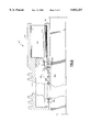
- FIG. 2 is a side elevation partial section of the optical module of FIG. 1, showing the connection of the invention between one of the optical sub-assemblies and the ceramic electrical interconnect structure within the housing;
- FIG. 3 is a schematic elevation view of the optical module in a machine of the invention for fluxless laser soldering
- FIG. 4 is a plan view of a specific flexible ribbon cable embodiment of this invention for laser soldering leads to interconnection pads on a ceramic substrate;
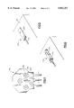
- FIG. 5 is an isometric view of a conductive pad of the thin film circuit on the top surface of a ceramic interconnect structure
- FIG. 6 is an isometric view of an interconnect pad of the invention in which a solder pad is attached on the top of the conductive pad of FIG. 4 on the ceramic interconnect structure;
- FIG. 7 is an isometric view of three leads extending from an end of a flexible ribbon cable and positioned across the top solder pads of FIG. 5 and illustrating a molybdenum surfaced tip of a probe of the invention holding a lead against a solder pad for laser soldering.
- FIG. 8 is an elevational view of the probe tip of the invention.
- FIG. 1 shows a specific embodiment of the optical module 100 of this invention.
- Longate optical sub-assembly 102 receives a first, optical signal in a port (not shown) in one longitudinal end of module 102.
- the module converts the first, optical signal into a first, electrical signal which is output through conductive pins 104 at the distal longitudinal end of the module.
- Pins 104 are soldered to flat, donut-shaped conductive, solder-wettable lands 105 encircling through holes at 106.
- the lands are on the surface of flexible ribbon cable 110 and are integrally connected to conductors 108 extending within dielectric layers of flexible ribbon cable 110.
- connection between pins 104 and cable 110 may be made by introducing solder preforms or solder paste and reflowing or preferably by mass soldering such as immersion or most preferably by wave soldering.
- the flexible ribbon cable is bent 90 degrees as shown so that exposed leads 112 of conductors 108 are positioned on interconnection pads 120 of thin film screen printed electrical circuit 122 which is on the top surface of interconnect structure 124 which is preferably of rigid construction and more preferably of ceramic construction.
- the connection of cable 110 with pads 120 is provided by laser soldering as later described in this specification.
- Electronic circuit 126 processes the first, electrical signal and transmits a first processed electrical signal.
- Electronic circuit 126 is connected through output conduits of electrical circuit 122 which are connected to pins 128.
- the first, processed, electrical signal is transmitted from electronic circuit 126, through electrical circuit 122, to pins 128.
- electrical interconnect structure 130 such as a flexible circuit board or a printed circuit board
- pins 128 couple with connectors 132 of an electrical circuit 134 which extends on the exterior and/or the interior of interconnect structure 130.
- the first, processed, electrical signal is transmitted from the pins into interconnect structure 130.
- a second, electrical signal is transmitted from external interconnect structure 130, through pins 128, through electrical circuit 122, and to electronic circuit 138 which processes the second electrical signal.
- optical sub-assembly 140 is connected through flexible ribbon cable 142 to interconnection pads 144 of electrical circuit 122 which is connected to electronic circuit 138.
- the second electrical signal is processed and transmitted to optical sub-assembly 140 which converts the second, processed, electrical signal into a second optical signal which is transmitted through a port (not shown) in one end of the module.
- Optical modules 102 and 140 and rigid interconnect structure 124 are mounted within a housing of two part construction preferably of cast aluminum which may be machined as required.
- the bottom of lower part 150 of the housing includes a matrix of apertures 152 through which pins 128 of interconnect structure 124 extend to communicate with interconnect structure 130. Alternately a window (not shown) could be provided in the bottom of lower part 150 for the pins.
- structure 124 is held in a fixed position in lower part 150 by adhesive, preferably epoxy.
- the optical sub-assemblies may also be fixed in position by an adhesive such as epoxy or may be positioned by keys to allow limited movement for adjustment to tolerances in the dimensions of plug in module 160.
- the top of upper part 154 of the housing includes fins 156 for cooling the optical module.
- Optical plug 160 connects into guide 162 to position optical connectors 164 and 166 in relation to apertures (not shown) in one end of each optical sub-assembly 102 and 140 respectively, so that bidirectional optical communication may be provided between the optical fibers of cable 168 and optical module 100.
- the substrate is metallized ceramic such as alumina and the circuit is produced by evaporation or sputtering and a selective subtractive lithographic process to produce a wiring layer.
- the metallization is 80 ⁇ chromium, 8,000-80,000 ⁇ copper, and finally another 80 ⁇ chromium.
- the substrate may be multilayer ceramic.
- the substrate may be a metal or resin such as fiberglass.
- the copper pads are 50 by 60 mils and the solder layer is produced by etching to remove the chromium surface from the pads followed by plating about 40 mils of 10/90 (Sn/Pb) solder onto the pads.
- Part of this invention is the discovery that when the pins of the optical sub-assemblies are bent and joined directly to the interconnection pads, there was a high rate of failure in the pins or joints over the life of the optical modules. It is also the discovery of applicants that these failures could be eliminated in the optical module of this invention by utilizing a flexible ribbon cable to connect between the pins of the optical sub-assembly and the ceramic interconnect structure.
- Flux should not be utilized in making the joint between the leads and the interconnection pads because integrated circuits are connected or will be connected to the top surface of the interconnect structure. Furthermore, due to high operating temperatures normal eutectic solders should not be utilized. Also, the electronic circuits are attached using flip-chip/solder ball technology. Due to thermal mismatch between the chip and substrate, the tin content is high to provide flexibility. Preferably, the solder is 20/80 to 3/97 and most preferably approximately 10/90 (Sn/Pb). Previous techniques of fluxless laser soldering could not provide a high quality, closely spaced joint on the ceramic substrate possibly because of the high heat transfer through the ceramic material. This invention has enabled high quality 10/90 (Sn/Pb) soldered connections on a ceramic substrate to be spaced closer than 2 mm.
- FIG. 2 is a partial section view of selected parts of optical module 100 of this invention mounted on a section of printed circuit board 130.
- Optical sub-assembly 140 and ceramic interconnect structure 124 with electronic circuit 144 are mounted between upper cover part 154 and lower part 150.
- Pins 104 extend axially from optical sub-assembly 140 and through passages at one end of flexible ribbon cable 110. The leads are wave soldered to lands (not shown) on the ribbon cable proximate to the passages.
- electrical conductors within dielectric layers of cable 110 extend from the lands to the distal end of the cable where they are exposed as leads 112 and laser soldered to interconnection pads 120 which are electrically connected to electronic circuit 144 for passing electrical signals between sub-assembly 140 and electronic circuit 144.
- Pins 128 pass through apertures 152 in the bottom plate of the lower part 150 to connect into the electrical circuit of printed circuit board 130.
- the electronic circuits are connected to the ceramic interconnect structure prior to connection to the optical sub-assemblies, therefore flux can not be used in the soldering operation because solvents such as water can not be used to clean the flux off from the substrate.
- FIG. 3 illustrates laser soldering machine 200 of the invention.
- Ceramic interconnect structure 202 is preferably bonded in the lower section 204 of the two-part aluminum housing.
- Optical sub-assembly 206 is also positioned in the lower section with leads 208 of flex cable 210 positioned across interconnection pad 212.
- Lower section 204 of the housing is automatically loaded in stage/conveyor 218 of laser soldering machine 200 and is positioned preferably by a motor 220 relative to laser apparatus 222 for automated laser soldering of lead 208 onto pad 212.
- Inert gas, preferably nitrogen, from source 224 is mixed with formic acid 226 preferably by bubbling the nitrogen through a reservoir of the acid to produce a mixture of inert gas and formic acid.
- the gas mixture is delivered to surround lead 208 and pad 212 with an atmosphere or cloud of inert gas mixed with formic acid for fluxless soldering.
- the robot may include a spring (not shown) to provide a preset spring load against the lead when the probe is extended.
- a beam (not shown) is directed by laser unit 221, into optic cable 223, and through head 222 onto lead 208 at 234 which is adjacent to tip 230 of probe 228.
- the beam heats the lead and the heat is conducted to the surface of pad 212 in contact with the lead to heat the contacting pad surface sufficient for soldering the lead to the pad.
- the heat from the laser beam reaches the probe tip therefore the tip is preferably constructed of a high temperature material such as molybdenum to provide long service life.
- Laser 222, motor 220 and robot 232 are connected to controller 236 which automatically directs the laser reflow soldering process.
- the laser unit is a Nd:YAG, CW, 60W laser as provided by MBB of Germany.
- the controller is an IBM PS/2.
- the robot includes an IBM System 7576 with a 7576 manipulator, 7532 industrial computer and a 7572 servo power module, the laser head includes optics and an optic fiber connected to the laser unit, a pilot laser, an IR measuring device, and a CCTV camera.
- FIG. 4 illustrates a specific embodiments of the flexible ribbon cable 240 of this invention with 3 conductors.
- 3 or 4 conductors can be used in optical modules.
- the ribbon cables are produced by laminating multiple layers of material which include at least one conductive layer and one dielectric layer. Alternatively, the layers may be built up. The thickness of the layers are selected to provide reliability, ease of construction and minimized material costs.
- the conductive layer is less than 0.3 mm thick and is sandwiched between two dielectric layers which are less than 0.1 mm thick.
- each cable apertures 242 have been prepared for soldered connection with pins (not shown) extending from one end of an optical sub-assembly.
- a window is provided in the dielectric layers to expose a land 244 attached to a conductor 246 both of an electrical circuit sandwiched between the dielectric layers of the cable.
- the lands may be for example circular or C-shaped and the electrical circuit of the land and conductor may be any thin layer of conductive solid such as copper or copper coated with chromium for enhanced adhesion with the dielectric layers.
- a layer of adhesive, preferably epoxy, may be provided to connect the conductive material and the dielectric.
- the conductors of the circuit extend out of the dielectric layers for soldered connection at line 248 to conductive pads (not shown) of the electrical circuit of a ceramic interconnect structure.
- FIG. 5 illustrates a section 250 of the electrical circuit on the surface of ceramic substrate 252.
- Circuit section 250 includes a rectangular conductive pad 254 integral with a narrower conductive path 256.
- FIG. 6 shows a completed interconnect pad 258 which includes a flat rectangular pad of approximately 10/90 (Sn/Pb) solder plated to the top of conductive pad 254 to provide a 10/90 (Sn/Pb) solder top surface 260 for reflow soldering to a lead.
- Sn/Pb 10/90 solder
- flexible ribbon cable 300 is positioned for attachment to three interconnection pads 302, 304 and 306 on the surface of ceramic substrate 308.
- Cable 302 includes three rectangular conductive paths 310, 312 and 314 generally enclosed between flexible dielectric layers 316 and 318.
- the conductive paths 310, 312 and 314 extend out of dielectric layers at the lower end of the ribbon cable as leads 320, 322, 324 respectively.
- the leads are pre-tinned, i.e., covered with a solder wettable/antioxidizing coating such as tin or preferably with eutectic 63/37 (Sn/Pb) solder.
- probe tip 330 presses against lead 320 to provide high quality thermal and mechanical contact between lead 320 and the 10/90 (Sn/Pb) solder top surface of interconnection pad 302 for soldered connection.
- the beam of a Nd-YAG laser is directed onto the lead at 332 which is adjacent to the end of probe tip 330 to heat lead 320 by incident radiation and to heat the top surface of pad 302 by conduction for reflow soldering the lead to the pad.
- tip 350 of probe 352 has notch 354 with internal sides 356 and 358 angled for contacting lead 360 only at edge corners 362 and 364 for minimizing the heat flow from the lead into the probe. This minimizes damage to the probe tip and allows more heat to flow into solder pad 366 for high temperature reflow soldering.
Abstract
Description
Claims (19)
Priority Applications (1)
| Application Number | Priority Date | Filing Date | Title |
|---|---|---|---|
| US08/794,761 US5852257A (en) | 1992-11-16 | 1996-05-30 | Optical module with fluxless laser reflow soldered joints |
Applications Claiming Priority (2)
| Application Number | Priority Date | Filing Date | Title |
|---|---|---|---|
| US07/976,620 US5604831A (en) | 1992-11-16 | 1992-11-16 | Optical module with fluxless laser reflow soldered joints |
| US08/794,761 US5852257A (en) | 1992-11-16 | 1996-05-30 | Optical module with fluxless laser reflow soldered joints |
Related Parent Applications (1)
| Application Number | Title | Priority Date | Filing Date |
|---|---|---|---|
| US07/976,620 Division US5604831A (en) | 1992-11-16 | 1992-11-16 | Optical module with fluxless laser reflow soldered joints |
Publications (1)
| Publication Number | Publication Date |
|---|---|
| US5852257A true US5852257A (en) | 1998-12-22 |
Family
ID=25524290
Family Applications (4)
| Application Number | Title | Priority Date | Filing Date |
|---|---|---|---|
| US07/976,620 Expired - Lifetime US5604831A (en) | 1992-11-16 | 1992-11-16 | Optical module with fluxless laser reflow soldered joints |
| US08/794,762 Expired - Fee Related US5742025A (en) | 1992-11-16 | 1996-05-30 | Laser reflow soldering process with lead-tin solder pads |
| US08/794,761 Expired - Fee Related US5852257A (en) | 1992-11-16 | 1996-05-30 | Optical module with fluxless laser reflow soldered joints |
| US08/660,665 Expired - Fee Related US5763854A (en) | 1992-11-16 | 1996-05-30 | Machine for laser reflow soldering |
Family Applications Before (2)
| Application Number | Title | Priority Date | Filing Date |
|---|---|---|---|
| US07/976,620 Expired - Lifetime US5604831A (en) | 1992-11-16 | 1992-11-16 | Optical module with fluxless laser reflow soldered joints |
| US08/794,762 Expired - Fee Related US5742025A (en) | 1992-11-16 | 1996-05-30 | Laser reflow soldering process with lead-tin solder pads |
Family Applications After (1)
| Application Number | Title | Priority Date | Filing Date |
|---|---|---|---|
| US08/660,665 Expired - Fee Related US5763854A (en) | 1992-11-16 | 1996-05-30 | Machine for laser reflow soldering |
Country Status (2)
| Country | Link |
|---|---|
| US (4) | US5604831A (en) |
| JP (1) | JP3077125B2 (en) |
Cited By (28)
| Publication number | Priority date | Publication date | Assignee | Title |
|---|---|---|---|---|
| US6095698A (en) * | 1997-08-08 | 2000-08-01 | Siemens Aktiengesellschaft | Hybrid connector |
| US6166330A (en) * | 1995-11-23 | 2000-12-26 | Gemplus S.C.A. | Housing for an extended-format releasable plug-in card |
| US6193135B1 (en) | 1999-09-13 | 2001-02-27 | Lucent Technologies Inc. | System for providing back-lighting of components during fluxless soldering |
| US6196446B1 (en) | 1999-09-13 | 2001-03-06 | Lucent Technologies Inc. | Automated fluxless soldering using inert gas |
| US6206276B1 (en) | 1999-09-13 | 2001-03-27 | Lucent Technologies Inc. | Direct-placement fluxless soldering using inert gas environment |
| US20030031418A1 (en) * | 2001-08-01 | 2003-02-13 | Satoshi Yoshikawa | Ball grid array element and optical communication module using the same |
| US20030159772A1 (en) * | 2002-02-27 | 2003-08-28 | Optronx, Inc. | Method for improving heat dissipation in optical transmitter |
| US20030183605A1 (en) * | 2002-01-31 | 2003-10-02 | Valeo Electronique Et Systemes De Liaison Of France | Method and equipment for welding conductors to substrates |
| US20040047570A1 (en) * | 2002-09-06 | 2004-03-11 | Paracer, Inc. | Circuit board construction for use in small form factor fiber optic communication system transponders |
| US20040047637A1 (en) * | 2002-09-06 | 2004-03-11 | Paracer, Inc. | Transponder assembly for use with parallel optics modules in fiber optic communications systems |
| US6749345B1 (en) * | 2002-05-24 | 2004-06-15 | National Semiconductor Corporation | Apparatus and method for electro-optical packages that facilitate the coupling of optical cables to printed circuit boards |
| US6767142B2 (en) | 2000-10-26 | 2004-07-27 | Fci | Optoelectronic emitter-receiver device |
| US6817782B2 (en) * | 2002-02-15 | 2004-11-16 | Finisar Corporation | Optical module with simplex port cap EMI shield |
| US6833526B2 (en) * | 2001-03-28 | 2004-12-21 | Visteon Global Technologies, Inc. | Flex to flex soldering by diode laser |
| US20050042838A1 (en) * | 2002-03-01 | 2005-02-24 | Garyainov Stanislav A | Fluxless assembly of chip size semiconductor packages |
| US6948861B2 (en) | 2001-08-01 | 2005-09-27 | Siemens Communications, Inc. | Heat sink for an optical module |
| US20060035454A1 (en) * | 2004-08-16 | 2006-02-16 | Ibm Corporation | Fluxless solder transfer and reflow process |
| US20060147159A1 (en) * | 2001-09-17 | 2006-07-06 | Stratos International, Inc | Transceiver assembly for use in fiber optics communications |
| US7073955B1 (en) | 2001-09-17 | 2006-07-11 | Stratos International, Inc. | Transceiver assembly for use in fiber optics communications |
| US7073954B1 (en) | 2001-09-17 | 2006-07-11 | Stratos International, Inc. | Transceiver assembly for use in fiber optics communications |
| US20070155197A1 (en) * | 2006-01-05 | 2007-07-05 | Rongsheng Miao | Laser package adaptor |
| US20080298750A1 (en) * | 2007-05-31 | 2008-12-04 | Finisar Corporation | Electromagnetic radiation shield for an optical subassembly |
| US20080298752A1 (en) * | 2007-05-31 | 2008-12-04 | Finisar Corporation | Electromagnetic radiation shield for an optical subassembly |
| US20080298041A1 (en) * | 2007-05-31 | 2008-12-04 | Finisar Corporation | Electromagnetic radiation shield for an optical subassembly |
| US20100158062A1 (en) * | 2008-10-13 | 2010-06-24 | Emcore Corporation | Adapted Semiconductor Laser Package |
| US20100248029A1 (en) * | 2009-01-07 | 2010-09-30 | A123 Systems, Inc. | Methods of welding battery terminals |
| US20110085767A1 (en) * | 2009-10-09 | 2011-04-14 | Emcore Corporation | Cooled Laser Module |
| US20120286904A1 (en) * | 2009-05-09 | 2012-11-15 | Fujitsu Limited | Connection terminal and transmission line |
Families Citing this family (58)
| Publication number | Priority date | Publication date | Assignee | Title |
|---|---|---|---|---|
| CA2161915A1 (en) * | 1994-11-02 | 1996-05-03 | Sosaku Sawada | Optical module circuit board having flexible structure |
| US6220878B1 (en) | 1995-10-04 | 2001-04-24 | Methode Electronics, Inc. | Optoelectronic module with grounding means |
| US5717533A (en) | 1995-01-13 | 1998-02-10 | Methode Electronics Inc. | Removable optoelectronic module |
| JP3624360B2 (en) * | 1996-04-24 | 2005-03-02 | 富士通株式会社 | Optical module |
| US6086265A (en) * | 1996-04-24 | 2000-07-11 | Fujitsu Limited | Fiber-detachable-type optical module |
| US5828031A (en) * | 1996-06-27 | 1998-10-27 | International Business Machines Corporation | Head transducer to suspension lead termination by solder ball place/reflow |
| US6046882A (en) * | 1996-07-11 | 2000-04-04 | International Business Machines Corporation | Solder balltape and method for making electrical connection between a head transducer and an electrical lead |
| US5896480A (en) * | 1996-10-22 | 1999-04-20 | Stewart Connector Systems, Inc. | Optical interconnection system |
| EP0868674A1 (en) * | 1996-10-23 | 1998-10-07 | JDS Uniphase Corporation | Optoelectronic device, holder suitable for use in such a device and method of manufacturing such a device |
| ES2140340B1 (en) * | 1998-03-13 | 2000-10-16 | Mecanismos Aux Es Ind S A M A | LASER WELDING PROCEDURE APPLICABLE TO THE JOINT OF PINS ON PRINTED CIRCUITS. |
| US6369924B1 (en) * | 1998-04-20 | 2002-04-09 | Stratos Lightwave, Inc. | Optical transceiver with enhanced shielding and related methods |
| US7003874B1 (en) * | 1998-09-03 | 2006-02-28 | Micron Technology, Inc. | Methods of bonding solder balls to bond pads on a substrate |
| US6168070B1 (en) * | 1998-10-14 | 2001-01-02 | Visteon Global Technologies, Inc. | Method for soldering DPAK-type electronic components to circuit boards |
| JP3074649B1 (en) * | 1999-02-23 | 2000-08-07 | インターナショナル・ビジネス・マシーンズ・コーポレ−ション | Lead-free solder powder, lead-free solder paste, and methods for producing them |
| US6278078B1 (en) | 1999-06-02 | 2001-08-21 | Lockheed Martin Corporation | Laser soldering method |
| US6220873B1 (en) | 1999-08-10 | 2001-04-24 | Stratos Lightwave, Inc. | Modified contact traces for interface converter |
| US6356686B1 (en) | 1999-09-03 | 2002-03-12 | International Business Machines Corporation | Optoelectronic device encapsulant |
| JP3397313B2 (en) | 1999-12-20 | 2003-04-14 | 富士通株式会社 | Semiconductor device manufacturing method and electronic component mounting method |
| US6863444B2 (en) * | 2000-12-26 | 2005-03-08 | Emcore Corporation | Housing and mounting structure |
| US6867377B2 (en) * | 2000-12-26 | 2005-03-15 | Emcore Corporation | Apparatus and method of using flexible printed circuit board in optical transceiver device |
| US6799902B2 (en) | 2000-12-26 | 2004-10-05 | Emcore Corporation | Optoelectronic mounting structure |
| TW570856B (en) | 2001-01-18 | 2004-01-11 | Fujitsu Ltd | Solder jointing system, solder jointing method, semiconductor device manufacturing method, and semiconductor device manufacturing system |
| US6851867B2 (en) * | 2001-04-14 | 2005-02-08 | Jds Uniphase Corporation | Cam-follower release mechanism for fiber optic modules with side delatching mechanisms |
| US6796715B2 (en) * | 2001-04-14 | 2004-09-28 | E20 Communications, Inc. | Fiber optic modules with pull-action de-latching mechanisms |
| US6692159B2 (en) * | 2001-04-14 | 2004-02-17 | E20 Communications, Inc. | De-latching mechanisms for fiber optic modules |
| US6635866B2 (en) | 2001-04-19 | 2003-10-21 | Internation Business Machines Corporation | Multi-functional fiber optic coupler |
| US6583385B1 (en) * | 2001-12-19 | 2003-06-24 | Visteon Global Technologies, Inc. | Method for soldering surface mount components to a substrate using a laser |
| US6680457B2 (en) * | 2002-01-15 | 2004-01-20 | Agilent Technologies, Inc. | Reflowing of solder joints |
| US20050140009A1 (en) * | 2002-06-17 | 2005-06-30 | Horst Groeninger | Method and apparatus for the production of an electronic component with external contact areas |
| US7118281B2 (en) * | 2002-08-09 | 2006-10-10 | Jds Uniphase Corporation | Retention and release mechanisms for fiber optic modules |
| KR100521081B1 (en) * | 2002-10-12 | 2005-10-14 | 삼성전자주식회사 | Fabrication and installation method of flip chip |
| JP3926724B2 (en) * | 2002-10-28 | 2007-06-06 | 富士通株式会社 | Receptacle type optical transmission / reception module and receptacle type optical transmission / reception module |
| US6863453B2 (en) * | 2003-01-28 | 2005-03-08 | Emcore Corporation | Method and apparatus for parallel optical transceiver module assembly |
| JP2005064206A (en) * | 2003-08-11 | 2005-03-10 | Niigata Seimitsu Kk | Method of soldering semiconductor part and mounting structure of semiconductor part |
| JP4659816B2 (en) * | 2004-02-27 | 2011-03-30 | フィニサー コーポレイション | Lead frame connector for optoelectronic devices, method of manufacturing optical transceiver module including the lead frame connector, and optical module using the lead frame connector |
| US20050242161A1 (en) * | 2004-04-30 | 2005-11-03 | Visteon Global Technologies, Inc. | Systems and methods for laser soldering flat flexible cable |
| EP2458635A1 (en) * | 2005-04-29 | 2012-05-30 | Finisar Corporation | Molded lead frame connector with one or more passive components |
| US20060289607A1 (en) * | 2005-06-28 | 2006-12-28 | Buchwalter Stephen L | Composite solder transfer moldplate structure and method of making same |
| US20070075057A1 (en) * | 2005-08-19 | 2007-04-05 | Yi-Hsi Chen | Method for fine tuning circuit and controlling impedance with laser process |
| JP2007071980A (en) * | 2005-09-05 | 2007-03-22 | Mitsubishi Electric Corp | Optical module |
| FR2891483B1 (en) * | 2005-10-05 | 2009-05-15 | Commissariat Energie Atomique | METHOD AND INSTALLATION OF LASER CUTTING / WELDING |
| US20070090156A1 (en) * | 2005-10-25 | 2007-04-26 | Ramanathan Lakshmi N | Method for forming solder contacts on mounted substrates |
| US7723224B2 (en) * | 2006-06-14 | 2010-05-25 | Freescale Semiconductor, Inc. | Microelectronic assembly with back side metallization and method for forming the same |
| US7672142B2 (en) * | 2007-01-05 | 2010-03-02 | Apple Inc. | Grounded flexible circuits |
| JP5019639B2 (en) * | 2009-01-30 | 2012-09-05 | 古河電気工業株式会社 | Parallel optical transmission equipment |
| JP5075139B2 (en) * | 2009-01-30 | 2012-11-14 | 古河電気工業株式会社 | Parallel optical transmission equipment |
| JP5323518B2 (en) * | 2009-01-30 | 2013-10-23 | 古河電気工業株式会社 | Parallel optical transmission equipment |
| JP2011023509A (en) * | 2009-07-15 | 2011-02-03 | Renesas Electronics Corp | Method for manufacturing semiconductor device, and semiconductor manufacturing apparatus used in the same |
| EP2287644B1 (en) * | 2009-08-18 | 2014-04-09 | Mitsubishi Electric Corporation | Light source device and method of producing the same |
| US9065236B2 (en) * | 2010-04-30 | 2015-06-23 | Seagate Technology | Method and apparatus for aligning a laser diode on a slider |
| US20140065320A1 (en) * | 2012-08-30 | 2014-03-06 | Dechao Lin | Hybrid coating systems and methods |
| KR20140054627A (en) * | 2012-10-29 | 2014-05-09 | 삼성전기주식회사 | Reflow device |
| JP5416269B2 (en) * | 2012-12-11 | 2014-02-12 | 古河電気工業株式会社 | Parallel optical transmission equipment |
| JP6354415B2 (en) * | 2013-08-14 | 2018-07-11 | 富士電機株式会社 | Laser welding machine and laser welding method using the same |
| KR102120722B1 (en) * | 2018-09-18 | 2020-06-09 | 레이저쎌 주식회사 | Laser reflow apparatus and method for electronic components with micron-class thickness |
| CN110943354B (en) * | 2018-10-10 | 2020-11-10 | 成都大唐线缆有限公司 | Hot-melting type quick connection method for digital cable |
| US11411650B2 (en) * | 2020-01-24 | 2022-08-09 | Applied Optoelectronics, Inc. | Component bridge for increasing mounting surface area on feedthrough device and an optical subassembly implementing same |
| US11627667B2 (en) | 2021-01-29 | 2023-04-11 | Orbotech Ltd. | High-resolution soldering |
Citations (19)
| Publication number | Priority date | Publication date | Assignee | Title |
|---|---|---|---|---|
| US4273413A (en) * | 1979-02-26 | 1981-06-16 | Amp Incorporated | Photoelectric element/optical cable connector |
| US4547039A (en) * | 1982-04-16 | 1985-10-15 | Amp Incorporated | Housing mountable on printed circuit board to interconnect fiber optic connectors |
| US4647148A (en) * | 1983-03-31 | 1987-03-03 | Tokyo Shibaura Denki Kabushiki Kaisha | Fiber optic receiver module |
| US4696101A (en) * | 1985-06-07 | 1987-09-29 | Vanzetti Systems, Inc. | Method and apparatus for placing and electrically connecting components on a printed circuit board |
| US4707067A (en) * | 1984-02-22 | 1987-11-17 | Siemens Aktiengesellschaft | Opto-electronic module housing |
| US4728787A (en) * | 1982-11-30 | 1988-03-01 | Thomson-Csf | Alignment process for an electro-optical device |
| US4993803A (en) * | 1989-05-18 | 1991-02-19 | General Motors Corporation | Electro-optical header connector |
| US5004317A (en) * | 1990-01-03 | 1991-04-02 | International Business Machines Corp. | Wire bond connection system with cancellation of mutual coupling |
| US5005939A (en) * | 1990-03-26 | 1991-04-09 | International Business Machines Corporation | Optoelectronic assembly |
| US5039194A (en) * | 1990-01-09 | 1991-08-13 | International Business Machines Corporation | Optical fiber link card |
| US5047835A (en) * | 1989-12-26 | 1991-09-10 | At&T Bell Laboratories | Lightwave packaging for pairs of optical devices |
| US5146526A (en) * | 1991-04-12 | 1992-09-08 | Amoco Corporation | Laser pigtail assembly and method |
| US5155786A (en) * | 1991-04-29 | 1992-10-13 | International Business Machines Corporation | Apparatus and a method for an optical fiber interface |
| US5202943A (en) * | 1991-10-04 | 1993-04-13 | International Business Machines Corporation | Optoelectronic assembly with alignment member |
| US5241614A (en) * | 1991-04-29 | 1993-08-31 | International Business Machines Corporation | Apparatus and a method for an optical fiber interface |
| US5276754A (en) * | 1992-07-06 | 1994-01-04 | Motorola, Inc. | Optoelectronic mount and method for making |
| US5295214A (en) * | 1992-11-16 | 1994-03-15 | International Business Machines Corporation | Optical module with tolerant wave soldered joints |
| US5416871A (en) * | 1993-04-09 | 1995-05-16 | Sumitomo Electric Industries, Ltd. | Molded optical connector module |
| US5475778A (en) * | 1993-10-21 | 1995-12-12 | Motorola, Inc. | Smart optical coupler and smart optical coupler system |
Family Cites Families (35)
| Publication number | Priority date | Publication date | Assignee | Title |
|---|---|---|---|---|
| US3614832A (en) * | 1966-03-09 | 1971-10-26 | Ibm | Decal connectors and methods of forming decal connections to solid state devices |
| US4018373A (en) * | 1973-06-28 | 1977-04-19 | Licentia Patent-Verwaltungs-G.M.B.H. | Device for bonding electrodes to semiconductor devices |
| JPS5633827A (en) * | 1979-08-29 | 1981-04-04 | Seiko Epson Corp | Photo etching method including surface treatment of substrate |
| DE2938254C2 (en) * | 1979-09-21 | 1982-04-22 | Siemens AG, 1000 Berlin und 8000 München | Flexible printed circuit |
| JPS56114340A (en) * | 1980-02-13 | 1981-09-08 | Mitsubishi Electric Corp | Bonding method |
| US4435740A (en) * | 1981-10-30 | 1984-03-06 | International Business Machines Corporation | Electric circuit packaging member |
| US4531044A (en) * | 1983-01-24 | 1985-07-23 | Ford Motor Company | Method of laser soldering |
| JPS6036587A (en) * | 1983-08-09 | 1985-02-25 | Sumitomo Heavy Ind Ltd | Detector for break of rope to drive leveler bar of coke oven |
| JPS60145698A (en) * | 1984-01-10 | 1985-08-01 | 日本電気株式会社 | Laser soldering inspecting device |
| JPS61153278U (en) * | 1985-03-13 | 1986-09-22 | ||
| EP0218069A1 (en) * | 1985-09-19 | 1987-04-15 | Siemens Aktiengesellschaft | Laser light welding process |
| US4646958A (en) * | 1985-10-31 | 1987-03-03 | International Business Machines Corp. | Fluxless soldering process using a silane atmosphere |
| US4745684A (en) * | 1986-12-17 | 1988-05-24 | Hughes Aircraft Company | Solder thickness measurement method and apparatus |
| US5152450A (en) * | 1987-01-26 | 1992-10-06 | Hitachi, Ltd. | Wire-bonding method, wire-bonding apparatus,and semiconductor device produced by the wire-bonding method |
| JPH01134885A (en) * | 1987-11-20 | 1989-05-26 | Furukawa Electric Co Ltd:The | Surface packaging method for connector |
| JPH01140570A (en) * | 1987-11-27 | 1989-06-01 | Nippon Telegr & Teleph Corp <Ntt> | Electric connector |
| JPH01187787A (en) * | 1988-01-20 | 1989-07-27 | Matsushita Electric Ind Co Ltd | Soldering method for hybrid integrated circuit |
| JPH01202704A (en) * | 1988-02-09 | 1989-08-15 | Fujitsu Ltd | Packing structure for optical submarine repeater internal unit |
| US4937006A (en) * | 1988-07-29 | 1990-06-26 | International Business Machines Corporation | Method and apparatus for fluxless solder bonding |
| US4894509A (en) * | 1988-12-13 | 1990-01-16 | International Business Machines Corporation | Laser assisted heater bar for multiple lead attachment |
| US5217154A (en) * | 1989-06-13 | 1993-06-08 | Small Precision Tools, Inc. | Semiconductor bonding tool |
| US5023426A (en) * | 1989-06-21 | 1991-06-11 | Honeywell Inc. | Robotic laser soldering apparatus for automated surface assembly of microscopic components |
| US5046658A (en) * | 1989-07-27 | 1991-09-10 | At&T Bell Laboratories | Method and apparatus for soldering articles |
| DE3939812C2 (en) * | 1989-12-01 | 1993-11-11 | Deutsche Aerospace | Laser soldering system for SMD elements |
| JP2844778B2 (en) * | 1989-12-28 | 1999-01-06 | ソニー株式会社 | How to solder two types of parts to a single-sided printed circuit board |
| JPH0831351B2 (en) * | 1990-01-12 | 1996-03-27 | 松下電器産業株式会社 | Covered wire soldering method |
| US4970624A (en) * | 1990-01-22 | 1990-11-13 | Molex Incorporated | Electronic device employing a conductive adhesive |
| US5090651A (en) * | 1990-01-31 | 1992-02-25 | Electrovert Ltd. | Gas curtain additives and zoned tunnel for soldering |
| JPH0428287A (en) * | 1990-05-23 | 1992-01-30 | Fujitsu Ltd | Mounting method of component on printed board |
| US5055652A (en) * | 1990-10-01 | 1991-10-08 | General Electric Company | Laser soldering of flexible leads |
| JPH04186696A (en) * | 1990-11-16 | 1992-07-03 | Mitsubishi Electric Corp | Bonding device |
| JP2549211B2 (en) * | 1991-01-16 | 1996-10-30 | 株式会社日立製作所 | Vapor soldering equipment |
| US5194710A (en) * | 1991-05-22 | 1993-03-16 | Cray Research, Inc. | Method and apparatus for laser masking of lead bonding |
| US5227604A (en) * | 1991-06-28 | 1993-07-13 | Digital Equipment Corporation | Atmospheric pressure gaseous-flux-assisted laser reflow soldering |
| JP2701183B2 (en) * | 1991-08-09 | 1998-01-21 | 株式会社小松製作所 | Liquid crystal mask laser marker |
-
1992
- 1992-11-16 US US07/976,620 patent/US5604831A/en not_active Expired - Lifetime
-
1993
- 1993-10-20 JP JP05262243A patent/JP3077125B2/en not_active Expired - Fee Related
-
1996
- 1996-05-30 US US08/794,762 patent/US5742025A/en not_active Expired - Fee Related
- 1996-05-30 US US08/794,761 patent/US5852257A/en not_active Expired - Fee Related
- 1996-05-30 US US08/660,665 patent/US5763854A/en not_active Expired - Fee Related
Patent Citations (19)
| Publication number | Priority date | Publication date | Assignee | Title |
|---|---|---|---|---|
| US4273413A (en) * | 1979-02-26 | 1981-06-16 | Amp Incorporated | Photoelectric element/optical cable connector |
| US4547039A (en) * | 1982-04-16 | 1985-10-15 | Amp Incorporated | Housing mountable on printed circuit board to interconnect fiber optic connectors |
| US4728787A (en) * | 1982-11-30 | 1988-03-01 | Thomson-Csf | Alignment process for an electro-optical device |
| US4647148A (en) * | 1983-03-31 | 1987-03-03 | Tokyo Shibaura Denki Kabushiki Kaisha | Fiber optic receiver module |
| US4707067A (en) * | 1984-02-22 | 1987-11-17 | Siemens Aktiengesellschaft | Opto-electronic module housing |
| US4696101A (en) * | 1985-06-07 | 1987-09-29 | Vanzetti Systems, Inc. | Method and apparatus for placing and electrically connecting components on a printed circuit board |
| US4993803A (en) * | 1989-05-18 | 1991-02-19 | General Motors Corporation | Electro-optical header connector |
| US5047835A (en) * | 1989-12-26 | 1991-09-10 | At&T Bell Laboratories | Lightwave packaging for pairs of optical devices |
| US5004317A (en) * | 1990-01-03 | 1991-04-02 | International Business Machines Corp. | Wire bond connection system with cancellation of mutual coupling |
| US5039194A (en) * | 1990-01-09 | 1991-08-13 | International Business Machines Corporation | Optical fiber link card |
| US5005939A (en) * | 1990-03-26 | 1991-04-09 | International Business Machines Corporation | Optoelectronic assembly |
| US5146526A (en) * | 1991-04-12 | 1992-09-08 | Amoco Corporation | Laser pigtail assembly and method |
| US5155786A (en) * | 1991-04-29 | 1992-10-13 | International Business Machines Corporation | Apparatus and a method for an optical fiber interface |
| US5241614A (en) * | 1991-04-29 | 1993-08-31 | International Business Machines Corporation | Apparatus and a method for an optical fiber interface |
| US5202943A (en) * | 1991-10-04 | 1993-04-13 | International Business Machines Corporation | Optoelectronic assembly with alignment member |
| US5276754A (en) * | 1992-07-06 | 1994-01-04 | Motorola, Inc. | Optoelectronic mount and method for making |
| US5295214A (en) * | 1992-11-16 | 1994-03-15 | International Business Machines Corporation | Optical module with tolerant wave soldered joints |
| US5416871A (en) * | 1993-04-09 | 1995-05-16 | Sumitomo Electric Industries, Ltd. | Molded optical connector module |
| US5475778A (en) * | 1993-10-21 | 1995-12-12 | Motorola, Inc. | Smart optical coupler and smart optical coupler system |
Cited By (48)
| Publication number | Priority date | Publication date | Assignee | Title |
|---|---|---|---|---|
| US6166330A (en) * | 1995-11-23 | 2000-12-26 | Gemplus S.C.A. | Housing for an extended-format releasable plug-in card |
| US6095698A (en) * | 1997-08-08 | 2000-08-01 | Siemens Aktiengesellschaft | Hybrid connector |
| US6193135B1 (en) | 1999-09-13 | 2001-02-27 | Lucent Technologies Inc. | System for providing back-lighting of components during fluxless soldering |
| US6196446B1 (en) | 1999-09-13 | 2001-03-06 | Lucent Technologies Inc. | Automated fluxless soldering using inert gas |
| US6206276B1 (en) | 1999-09-13 | 2001-03-27 | Lucent Technologies Inc. | Direct-placement fluxless soldering using inert gas environment |
| US6767142B2 (en) | 2000-10-26 | 2004-07-27 | Fci | Optoelectronic emitter-receiver device |
| US6833526B2 (en) * | 2001-03-28 | 2004-12-21 | Visteon Global Technologies, Inc. | Flex to flex soldering by diode laser |
| US20030031418A1 (en) * | 2001-08-01 | 2003-02-13 | Satoshi Yoshikawa | Ball grid array element and optical communication module using the same |
| US6948861B2 (en) | 2001-08-01 | 2005-09-27 | Siemens Communications, Inc. | Heat sink for an optical module |
| US20060153506A1 (en) * | 2001-09-17 | 2006-07-13 | Stratos International, Inc. | Transceiver assembly for use in fiber optics communications |
| US20060147159A1 (en) * | 2001-09-17 | 2006-07-06 | Stratos International, Inc | Transceiver assembly for use in fiber optics communications |
| US20060159403A1 (en) * | 2001-09-17 | 2006-07-20 | Stratos International, Inc. | Transceiver assembly for use in fiber optics communications |
| US7097365B2 (en) | 2001-09-17 | 2006-08-29 | Stratos International, Inc. | Transceiver assembly for use in fiber optics communications |
| US20060153505A1 (en) * | 2001-09-17 | 2006-07-13 | Stratos International, Inc. | Transceiver assembly for use in fiber optics communications |
| US7073954B1 (en) | 2001-09-17 | 2006-07-11 | Stratos International, Inc. | Transceiver assembly for use in fiber optics communications |
| US7101090B2 (en) | 2001-09-17 | 2006-09-05 | Stratos International, Inc. | Transceiver assembly for use in fiber optics communications |
| US7073955B1 (en) | 2001-09-17 | 2006-07-11 | Stratos International, Inc. | Transceiver assembly for use in fiber optics communications |
| US20030183605A1 (en) * | 2002-01-31 | 2003-10-02 | Valeo Electronique Et Systemes De Liaison Of France | Method and equipment for welding conductors to substrates |
| US6903303B2 (en) | 2002-01-31 | 2005-06-07 | Valeo Electronique Et Systemes De Liaison | Method and equipment for welding conductors to substrates |
| US6817782B2 (en) * | 2002-02-15 | 2004-11-16 | Finisar Corporation | Optical module with simplex port cap EMI shield |
| US6773532B2 (en) | 2002-02-27 | 2004-08-10 | Jds Uniphase Corporation | Method for improving heat dissipation in optical transmitter |
| US20030159772A1 (en) * | 2002-02-27 | 2003-08-28 | Optronx, Inc. | Method for improving heat dissipation in optical transmitter |
| US20050042838A1 (en) * | 2002-03-01 | 2005-02-24 | Garyainov Stanislav A | Fluxless assembly of chip size semiconductor packages |
| US7098072B2 (en) | 2002-03-01 | 2006-08-29 | Agng, Llc | Fluxless assembly of chip size semiconductor packages |
| US6749345B1 (en) * | 2002-05-24 | 2004-06-15 | National Semiconductor Corporation | Apparatus and method for electro-optical packages that facilitate the coupling of optical cables to printed circuit boards |
| US20060133820A1 (en) * | 2002-09-06 | 2006-06-22 | Stratos International, Inc. | Transponder assembly for use with parallel optics modules in fiber optic communications systems |
| US20060133821A1 (en) * | 2002-09-06 | 2006-06-22 | Stratos International, Inc. | Transponder assembly for use with parallel optics modules in fiber optic communications systems |
| US7064962B2 (en) * | 2002-09-06 | 2006-06-20 | Stratos International, Inc. | Transponder assembly for use with parallel optics modules in fiber optic communications systems |
| US7504668B2 (en) * | 2002-09-06 | 2009-03-17 | Stratos International, Inc. | Transponder assembly for use with parallel optics modules in fiber optic communications systems |
| US6903934B2 (en) * | 2002-09-06 | 2005-06-07 | Stratos International, Inc. | Circuit board construction for use in small form factor fiber optic communication system transponders |
| US20040047637A1 (en) * | 2002-09-06 | 2004-03-11 | Paracer, Inc. | Transponder assembly for use with parallel optics modules in fiber optic communications systems |
| US20040047570A1 (en) * | 2002-09-06 | 2004-03-11 | Paracer, Inc. | Circuit board construction for use in small form factor fiber optic communication system transponders |
| US7463831B2 (en) | 2002-09-06 | 2008-12-09 | Stratos International, Inc. | Transponder assembly for use with parallel optics modules in fiber optic communications systems |
| US7332424B2 (en) | 2004-08-16 | 2008-02-19 | International Business Machines Corporation | Fluxless solder transfer and reflow process |
| US20060035454A1 (en) * | 2004-08-16 | 2006-02-16 | Ibm Corporation | Fluxless solder transfer and reflow process |
| US20070155197A1 (en) * | 2006-01-05 | 2007-07-05 | Rongsheng Miao | Laser package adaptor |
| US7731431B2 (en) | 2007-05-31 | 2010-06-08 | Finisar Corporation | Electromagnetic radiation shield for an optical subassembly |
| US20080298041A1 (en) * | 2007-05-31 | 2008-12-04 | Finisar Corporation | Electromagnetic radiation shield for an optical subassembly |
| US20080298752A1 (en) * | 2007-05-31 | 2008-12-04 | Finisar Corporation | Electromagnetic radiation shield for an optical subassembly |
| US7621678B2 (en) | 2007-05-31 | 2009-11-24 | Finisar Corporation | Electromagnetic radiation shield for an optical subassembly |
| US20080298750A1 (en) * | 2007-05-31 | 2008-12-04 | Finisar Corporation | Electromagnetic radiation shield for an optical subassembly |
| US7762729B2 (en) * | 2007-05-31 | 2010-07-27 | Finisar Corporation | Electromagnetic radiation shield for an optical subassembly |
| US20100158062A1 (en) * | 2008-10-13 | 2010-06-24 | Emcore Corporation | Adapted Semiconductor Laser Package |
| US8189645B2 (en) | 2008-10-13 | 2012-05-29 | Emcore Corporation | Adapted semiconductor laser package |
| US20100248029A1 (en) * | 2009-01-07 | 2010-09-30 | A123 Systems, Inc. | Methods of welding battery terminals |
| US20120286904A1 (en) * | 2009-05-09 | 2012-11-15 | Fujitsu Limited | Connection terminal and transmission line |
| US8491316B2 (en) * | 2009-05-09 | 2013-07-23 | Fujitsu Limited | Connection terminal and transmission line |
| US20110085767A1 (en) * | 2009-10-09 | 2011-04-14 | Emcore Corporation | Cooled Laser Module |
Also Published As
| Publication number | Publication date |
|---|---|
| US5742025A (en) | 1998-04-21 |
| US5604831A (en) | 1997-02-18 |
| US5763854A (en) | 1998-06-09 |
| JP3077125B2 (en) | 2000-08-14 |
| JPH06267632A (en) | 1994-09-22 |
Similar Documents
| Publication | Publication Date | Title |
|---|---|---|
| US5852257A (en) | Optical module with fluxless laser reflow soldered joints | |
| US5295214A (en) | Optical module with tolerant wave soldered joints | |
| US7629537B2 (en) | Single layer flex circuit | |
| US7215886B2 (en) | Optical communication module | |
| US5539848A (en) | Optical waveguide module and method of making | |
| US7439449B1 (en) | Flexible circuit for establishing electrical connectivity with optical subassembly | |
| EP0535473B1 (en) | Optoelectronic assembly with alignment member | |
| EP1028341B1 (en) | Integrated packaging system for optical communications devices that provides automatic alignment with optical fibers | |
| US7446261B2 (en) | Flexible circuit boards with tooling cutouts for optoelectronic modules | |
| US7306377B2 (en) | Integrated optical sub-assembly having epoxy chip package | |
| EP1499167B1 (en) | Folded flex circuit interconnect having a grid array interface | |
| JP4015440B2 (en) | Optical communication module | |
| US7499614B2 (en) | Passive alignment of VCSELs to waveguides in opto-electronic cards and printed circuit boards | |
| US6151173A (en) | Assembly of optical components optically aligned and method for making this assembly | |
| US7311240B2 (en) | Electrical circuits with button plated contacts and assembly methods | |
| EP0331436B1 (en) | Optical communication apparatus | |
| US5008656A (en) | Flexible cable assembly | |
| EP2211217A1 (en) | Printed circuit board fiberoptical transceiver in surface mount technology (SMT) | |
| GB2169750A (en) | Flexible cable assembly | |
| US6285554B1 (en) | Method and an arrangement for the electrical contact of components | |
| WO2018074654A1 (en) | Package for sealing flexible circuit board and metal case | |
| US7053314B1 (en) | Methods and apparatus for providing a signal to a circuit board component | |
| CA1260623A (en) | Flexible cable assembly | |
| US7717627B2 (en) | Electrical component connector with misalignment compensation | |
| CN116867162A (en) | Soft board, connector and printed circuit board |
Legal Events
| Date | Code | Title | Description |
|---|---|---|---|
| FPAY | Fee payment |
Year of fee payment: 4 |
|
| AS | Assignment |
Owner name: JDS UNIPHASE CORPORATION, CALIFORNIA Free format text: ASSIGNMENT OF ASSIGNORS INTEREST;ASSIGNOR:INTERNATIONAL BUSINESS MACHINES CORPORATION;REEL/FRAME:012946/0429 Effective date: 20011227 |
|
| FPAY | Fee payment |
Year of fee payment: 8 |
|
| REMI | Maintenance fee reminder mailed | ||
| LAPS | Lapse for failure to pay maintenance fees | ||
| STCH | Information on status: patent discontinuation |
Free format text: PATENT EXPIRED DUE TO NONPAYMENT OF MAINTENANCE FEES UNDER 37 CFR 1.362 |
|
| FP | Lapsed due to failure to pay maintenance fee |
Effective date: 20101222 |
|
| FEPP | Fee payment procedure |
Free format text: PAYOR NUMBER ASSIGNED (ORIGINAL EVENT CODE: ASPN); ENTITY STATUS OF PATENT OWNER: LARGE ENTITY |