US5865791A - Atrial appendage stasis reduction procedure and devices - Google Patents
Atrial appendage stasis reduction procedure and devices Download PDFInfo
- Publication number
- US5865791A US5865791A US08/880,711 US88071197A US5865791A US 5865791 A US5865791 A US 5865791A US 88071197 A US88071197 A US 88071197A US 5865791 A US5865791 A US 5865791A
- Authority
- US
- United States
- Prior art keywords
- atrial appendage
- catheter
- lasso
- appendage
- portions
- Prior art date
- Legal status (The legal status is an assumption and is not a legal conclusion. Google has not performed a legal analysis and makes no representation as to the accuracy of the status listed.)
- Expired - Fee Related
Links
Images


Classifications
-
- A—HUMAN NECESSITIES
- A61—MEDICAL OR VETERINARY SCIENCE; HYGIENE
- A61B—DIAGNOSIS; SURGERY; IDENTIFICATION
- A61B17/00—Surgical instruments, devices or methods, e.g. tourniquets
- A61B17/02—Surgical instruments, devices or methods, e.g. tourniquets for holding wounds open; Tractors
- A61B17/0218—Surgical instruments, devices or methods, e.g. tourniquets for holding wounds open; Tractors for minimally invasive surgery
-
- A—HUMAN NECESSITIES
- A61—MEDICAL OR VETERINARY SCIENCE; HYGIENE
- A61B—DIAGNOSIS; SURGERY; IDENTIFICATION
- A61B17/00—Surgical instruments, devices or methods, e.g. tourniquets
- A61B17/00234—Surgical instruments, devices or methods, e.g. tourniquets for minimally invasive surgery
-
- A—HUMAN NECESSITIES
- A61—MEDICAL OR VETERINARY SCIENCE; HYGIENE
- A61B—DIAGNOSIS; SURGERY; IDENTIFICATION
- A61B17/00—Surgical instruments, devices or methods, e.g. tourniquets
- A61B17/064—Surgical staples, i.e. penetrating the tissue
-
- A—HUMAN NECESSITIES
- A61—MEDICAL OR VETERINARY SCIENCE; HYGIENE
- A61B—DIAGNOSIS; SURGERY; IDENTIFICATION
- A61B17/00—Surgical instruments, devices or methods, e.g. tourniquets
- A61B17/12—Surgical instruments, devices or methods, e.g. tourniquets for ligaturing or otherwise compressing tubular parts of the body, e.g. blood vessels, umbilical cord
- A61B17/12009—Implements for ligaturing other than by clamps or clips, e.g. using a loop with a slip knot
- A61B17/12013—Implements for ligaturing other than by clamps or clips, e.g. using a loop with a slip knot for use in minimally invasive surgery, e.g. endoscopic surgery
-
- A—HUMAN NECESSITIES
- A61—MEDICAL OR VETERINARY SCIENCE; HYGIENE
- A61B—DIAGNOSIS; SURGERY; IDENTIFICATION
- A61B17/00—Surgical instruments, devices or methods, e.g. tourniquets
- A61B17/04—Surgical instruments, devices or methods, e.g. tourniquets for suturing wounds; Holders or packages for needles or suture materials
- A61B17/0469—Suturing instruments for use in minimally invasive surgery, e.g. endoscopic surgery
-
- A—HUMAN NECESSITIES
- A61—MEDICAL OR VETERINARY SCIENCE; HYGIENE
- A61B—DIAGNOSIS; SURGERY; IDENTIFICATION
- A61B17/00—Surgical instruments, devices or methods, e.g. tourniquets
- A61B17/00234—Surgical instruments, devices or methods, e.g. tourniquets for minimally invasive surgery
- A61B2017/00238—Type of minimally invasive operation
- A61B2017/00243—Type of minimally invasive operation cardiac
-
- A—HUMAN NECESSITIES
- A61—MEDICAL OR VETERINARY SCIENCE; HYGIENE
- A61B—DIAGNOSIS; SURGERY; IDENTIFICATION
- A61B17/00—Surgical instruments, devices or methods, e.g. tourniquets
- A61B17/00234—Surgical instruments, devices or methods, e.g. tourniquets for minimally invasive surgery
- A61B2017/00349—Needle-like instruments having hook or barb-like gripping means, e.g. for grasping suture or tissue
-
- A—HUMAN NECESSITIES
- A61—MEDICAL OR VETERINARY SCIENCE; HYGIENE
- A61B—DIAGNOSIS; SURGERY; IDENTIFICATION
- A61B17/00—Surgical instruments, devices or methods, e.g. tourniquets
- A61B17/04—Surgical instruments, devices or methods, e.g. tourniquets for suturing wounds; Holders or packages for needles or suture materials
- A61B17/0401—Suture anchors, buttons or pledgets, i.e. means for attaching sutures to bone, cartilage or soft tissue; Instruments for applying or removing suture anchors
- A61B2017/044—Suture anchors, buttons or pledgets, i.e. means for attaching sutures to bone, cartilage or soft tissue; Instruments for applying or removing suture anchors with a threaded shaft, e.g. screws
- A61B2017/0443—Suture anchors, buttons or pledgets, i.e. means for attaching sutures to bone, cartilage or soft tissue; Instruments for applying or removing suture anchors with a threaded shaft, e.g. screws the shaft being resilient and having a coiled or helical shape in the released state
-
- A—HUMAN NECESSITIES
- A61—MEDICAL OR VETERINARY SCIENCE; HYGIENE
- A61B—DIAGNOSIS; SURGERY; IDENTIFICATION
- A61B17/00—Surgical instruments, devices or methods, e.g. tourniquets
- A61B17/04—Surgical instruments, devices or methods, e.g. tourniquets for suturing wounds; Holders or packages for needles or suture materials
- A61B17/0401—Suture anchors, buttons or pledgets, i.e. means for attaching sutures to bone, cartilage or soft tissue; Instruments for applying or removing suture anchors
- A61B2017/0464—Suture anchors, buttons or pledgets, i.e. means for attaching sutures to bone, cartilage or soft tissue; Instruments for applying or removing suture anchors for soft tissue
-
- A—HUMAN NECESSITIES
- A61—MEDICAL OR VETERINARY SCIENCE; HYGIENE
- A61B—DIAGNOSIS; SURGERY; IDENTIFICATION
- A61B17/00—Surgical instruments, devices or methods, e.g. tourniquets
- A61B17/04—Surgical instruments, devices or methods, e.g. tourniquets for suturing wounds; Holders or packages for needles or suture materials
- A61B17/0469—Suturing instruments for use in minimally invasive surgery, e.g. endoscopic surgery
- A61B2017/048—Suturing instruments for use in minimally invasive surgery, e.g. endoscopic surgery for reducing heart wall tension, e.g. sutures with a pad on each extremity
-
- A—HUMAN NECESSITIES
- A61—MEDICAL OR VETERINARY SCIENCE; HYGIENE
- A61B—DIAGNOSIS; SURGERY; IDENTIFICATION
- A61B17/00—Surgical instruments, devices or methods, e.g. tourniquets
- A61B17/064—Surgical staples, i.e. penetrating the tissue
- A61B2017/0649—Coils or spirals
-
- A—HUMAN NECESSITIES
- A61—MEDICAL OR VETERINARY SCIENCE; HYGIENE
- A61B—DIAGNOSIS; SURGERY; IDENTIFICATION
- A61B17/00—Surgical instruments, devices or methods, e.g. tourniquets
- A61B17/34—Trocars; Puncturing needles
- A61B2017/348—Means for supporting the trocar against the body or retaining the trocar inside the body
- A61B2017/3482—Means for supporting the trocar against the body or retaining the trocar inside the body inside
- A61B2017/3484—Anchoring means, e.g. spreading-out umbrella-like structure
- A61B2017/3488—Fixation to inner organ or inner body tissue
Definitions
- This invention relates to the reduction of regions of blood stasis and ultimately thrombus formation in such regions, particularly in the atrial appendages for patients with atrial fibrillation. More specifically, the invention relates to procedures and devices for affixing the atrial appendages in an orientation that reduces subsequent formation of thrombus.
- the atria must enable organized electrical propagation from the SA Node to the AV Node to stimulate the atria to contract in an organized way to transport blood from the atria to the ventricles, and to provide timed stimulation of the ventricles.
- the atrial appendages are especially important in the transport of blood because they have a sack-like geometry with a neck potentially more narrow than the pouch. In this case, contraction of the appendage is essential to maintain an average absolute blood velocity high enough to eliminate potential stasis regions which may lead to thrombus formation.
- Atrial fibrillation and abnormalities which may lead to atrial fibrillation are often associated with abnormal electrical propagation through the heart leading to inefficient transport of blood in certain regions of the atria, and/or an enlargement of one or both atria to up to 2-3 times the normal size.
- Atrial fibrillation has often been treated either by administration of drugs or through surgical procedures, for example, procedures which surgically create a maze pattern in the atria which reduces the probability of fibrillation.
- the typical access points into the interior of the atria during a surgical procedure are the atrial appendages. Therefore, at the conclusion of the surgical procedure, the region occupied by the atrial appendages is eliminated by surgically removing the appendages. This mitigates subsequent problems resulting from blood stasis in the atrial appendages as well as from electrical isolation of the appendages from the rest of the atria.
- maze-like procedures have been developed utilizing catheters which may create long thin lesions to effectively create a maze for electrical conduction in a predetermined path.
- minimally invasive procedures may result in regions of continued blood stasis, particularly in the atrial appendages due to electrical isolation of the appendages or decreased contractility of the tissue due to the destruction of large regions of atrial tissue.
- the response of the atria to permanent conversion from atrial fibrillation to sinus rhythm after a catheter-based and/or surgical maze procedure has not been proven to return appendage function to normal.
- An important aspect of the invention involves providing methods and devices to reposition the atrial appendages, for example by inversion thereof either totally or partially.
- several embodiments of devices are provided for grabbing or otherwise attaching themselves to an appendage wall and either inverting or otherwise pulling the walls of the appendage together to reduce the size of the region of potential blood stasis, and consequently the effective volume of the affected atrium.
- a method reduces the effective volume of an atrial appendage by introducing intravascularly into the atrium a first catheter, which is provided at its distal end with a loop or lasso.
- the method introduces a second catheter within the perimeter of the loop or lasso and attaches the second catheter to an interior surface of an atrial appendage.
- the method pulls the atrial appendage through said loop to cause inversion thereof.
- a probe device for manipulating an interior tissue surface.
- the probe device comprises a first elongated catheter body having a first distal end assembly comprising means for repositioning said tissue surface.
- the probe device also includes a second elongated catheter body having a second distal end assembly comprising means for affixing said tissue surface in said repositioned orientation.
- the probe deice further includes at least one external control means operatively connected to one of said first or second distal end assemblies for selectively effecting said repositioning and affixing thereof.
- a method reduces the effective volume of an atrial appendage by deploying a first device into the atrium, the first device carrying a loop structure having a perimeter, and deploying a second device within the perimeter of said loop structure.
- the method attaches the second device to an interior surface of an atrial appendage, and pulls the atrial appendage through said loop structure to cause inversion thereof.
- a system for manipulating an interior tissue surface comprises a first device carrying a first element to affect positioning of the tissue surface in a repositioned orientation.
- the system also includes a second device usable in association with the first device.
- the second device carries a second element to affix the tissue surface in the repositioned orientation affected by the first device.
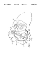
- FIG. 1 is a fragmentary view, with parts in section, illustrating introduction of a catheter into the right atrium of a heart in accordance with the invention
- FIG. 2 is a fragmentary view, with parts in section, showing introduction of a catheter into the right atrium of the heart via the femoral vein;
- FIG. 3 is a fragmentary view showing the right atrium with the catheter introduced therein and with the right atrial appendage inverted;
- FIG. 4 is a fragmentary view of the left atrium, with parts in section, illustrating introduction of a catheter into the left atrial appendage via a retrograde procedure;
- FIG. 5 is a fragmentary view, with parts in section, showing positioning of a catheter on the endocardial surface of a left atrial appendage using a transeptal procedure;
- FIG. 6 shows introduction of a catheter via a transeptal approach for inversion of the left atrial appendage
- FIG. 7 is a side view illustrating a helical coil attaching catheter used in connection with the invention.
- FIG. 8 is a sectional view illustrating a helical coil catheter with an independently rotatable hollow coil assembly with a lumen extending therethrough;
- FIG. 9 is a sectional view showing the insertion of the helical coil catheter in FIG. 7 into the myocardium to provide a focal point for pulling the appendage;
- FIG. 10 illustrates the inversion of the appendage wall shown in FIG. 9 utilizing the catheter helical coil assembly shown in FIG. 7;
- FIG. 11 is a fragmentary view showing the introduction through the helical coil assembly of FIG. 7 of a marking contrast material
- FIG. 12A is a sectional view of a catheter distal tip employing a three prong attaching catheter
- FIG. 12B is a sectional view of a catheter similar to that shown in FIG. 12A except that the prongs extend radially outward;
- FIG. 13 is a fragmentary view illustrating attachment of the catheter of FIG. 12A to an appendage wall
- FIG. 14 is a fragmentary view illustrating use of the catheter of FIG. 12A for inversion of an appendage wall
- FIG. 15 is a fragmentary view of the distal tip of the catheter of FIG. 12A retracted into a protective sheath;
- FIG. 16A is a fragmentary side view of a catheter distal section illustrating a hollow needle incorporating an internal extending, expandable type attachment/pulling element;
- FIG. 16B is a side view of the attachment/pulling element of FIG. 16A in an expanded configuration
- FIG. 17 is a fragmentary view illustrating another attachment/pulling element configuration which may be used to provide an attachment point with which to invert an atrial appendage;
- FIG. 18 is a fragmentary view showing a catheter distal tip carrying a compound loop device
- FIG. 19A illustrates an inverting catheter used in conjunction with a compound loop support catheter
- FIG. 19B is a fragmentary side view illustrating the inversion of an atrial appendage utilizing the devices shown in FIG. 19A;
- FIG. 20 is a fragmentary side view showing the use of a grasping catheter of the general type shown in FIG. 12A in conjunction with a lasso catheter for maintaining the walls of the inverted appendage together;
- FIGS. 21 and 22A are fragmentary views of the combination shown in FIG. 20 illustrating further steps of tying the appendages in an inverted orientation;
- FIG. 22B is a schematic showing one embodiment of a tying mechanism for use in the lasso catheter of FIGS. 20-22A;
- FIGS. 23 and 24A are fragmentary views illustrating the use of a catheter of the general type shown in FIG. 7 in conjunction with a releasable lasso catheter and showing the introduction of a biocompatible adhesive/filler material into the space outside of the inverted appendage;
- FIG. 24B is a fragmentary view showing the withdrawal of a catheter of the type shown in FIG. 7 after affixing in place an inverted appendage with a stabilizing filler material;
- FIG. 25 is a fragmentary sectional view showing a catheter with dual infusion ports for introduction of fluid materials
- FIG. 26 is a fragmentary view showing the use of a further embodiment of a lasso catheter, which is made of a metallic coil or other electrical conductor and is connected to an RF Generator for use in thermally fusing the appendage walls;
- FIG. 27A is a fragmentary view showing the application over an inverted appendage of a metallic mesh
- FIGS. 27B and 27C are fragmentary sectional views of a catheter mechanism used to expand the metallic mesh during insertion over the inverted appendage;
- FIG. 28 is a fragmentary sectional view showing the insertion of a helical metallic winding made from a memory transitional material which upon introduction through the appendage expands or contracts to its original form at body temperature and holds the appendage in place;
- FIG. 29 is a sectional view of a catheter containing an expandable anchor for insertion into an inverted appendage
- FIG. 30 is a cross-sectional view taken along 30--30 of FIG. 29;
- FIG. 31A is a cross-sectional view of an appendage showing the use of insertable expandable anchors in conjunction with a draw string;
- FIG. 31B is a cross-sectional view showing the appendage of FIG. 31A after it has been drawn together;
- FIG. 31C is a cross-sectional view showing a single expandable anchor inserted into an appendage wall
- FIG. 32A is a sectional view of a catheter containing an alternative type of expandable anchor for insertion into an inverted appendage;
- FIG. 32B is a cross-sectional view showing a single expandable anchor of the type shown in FIG. 32A inserted into an appendage wall;
- FIG. 33A is a side view of a handle mechanism for a catheter with a fixed hollow needle and an access point for an internal stylet mechanism
- FIG. 33B is a side view of a handle mechanism for a catheter with a moveable hollow needle and an access point for an internal stylet mechanism;
- FIG. 34 is a fragmentary view, with parts in section, illustrating introduction of a catheter into pericardium by means of a thoracostomy in accordance with the invention.
- FIG. 35 is an enlarged fragmentary view, with parts in section, of one embodiment of a catheter usable in the procedure shown in FIG. 34.
- FIGS. 1-3 show, in fragmentary fashion, the right atrium 10, the superior vena cava 12, the inferior vena cava 13, the ascending aorta 14, the right atrial appendage 16, the membranous septum 18, the right atrial freewall 20, the tricuspid valve 22, the opening of the coronary sinus 24, the valve of the coronary sinus 26, and the fossa ovalis 28.
- FIGS. 4-6 A left atrium 11 is shown in FIGS. 4-6. There are also seen therein the aortic valve 15, the left atrial appendage 17, the left superior pulmonary vein 19, the mitral valve 21, and the left ventricle 32.
- a catheter 40 is shown generally being introduced into the atria of a heart through various cardiovascular introduction passageways as will be discussed hereinafter.
- the point of attachment of catheter 40 to the wall of an atrial appendage 16 or 17 is indicated generally at 42.
- FIGS. 1-6 various ways of entering a heart chamber and positioning a catheter tip on the interior wall of the atrial appendages are illustrated.
- a catheter 40 is shown being advanced through the jugular vein past the superior vena cava 12 and into the right atrium 10 where it is steered so the tip is positioned on the endocardial surface of the right atrial appendage 16 where attachment is made.
- FIG. 2 illustrates a procedure for introducing the catheter 40 through the femoral vein into the right atrium 10 and then into the right atrial appendage 16.
- FIG. 3 illustrates the inversion of the right atrial appendage 16 using the catheter 40 introduced as shown in FIG. 2.
- FIG. 4 illustrates the positioning of a catheter distal tip at a point 42 on the endocardial surface of the left atrial appendage 17 utilizing a retrograde procedure.
- a sheath with a preformed configuration may be required to maneuver the catheter tip down through the aorta 14 and up through the mitral valve 21. In addition, such a sheath would provide additional support for maneuvering the tip of the catheter.
- FIG. 5 shows positioning of a catheter tip at a point 42 on the endocardial surface of the left atrial appendage 17 utilizing a transeptal introduction. Transeptal introduction is achieved by inserting an introducer or sheath with an internal dilator through the femoral or jugular vein and into the interior of the right atrium.
- a long hollow needle with a preformed curve and a sharpened distal tip is introduced through the dilator and is forcibly inserted through the fossa ovalis 28.
- a radiopaque contrast material is injected through the needle to ensure the needle is in the left atrium as opposed to being in the pericardial space, aorta, or other undesired location.
- FIG. 6 shows the inversion of the left atrial appendage 17 after catheter 40 has been attached at point 42 and by using a transeptal approach as shown in FIG. 5.
- the use of such delivery systems as sheaths is shown in pending U.S. application Ser. No. 08/136,218, filed Oct. 14, 1993, and entitled "Cardiac Mapping and Ablation Systems.”
- the catheter 50 includes a catheter body 52 having a distal tip portion 54.
- a hollow coil 58 is attached to the catheter distal tip 54 and has a lumen 55 extending from the proximal end of the coil at the distal tip attachment point to the catheter handle assembly (not shown), The coil 58 is rotated by torquing the catheter body 52.
- the catheter body 52 may be provided with a steering mechanism 57, for example, of the type shown in Lundquist and Thompson U.S. Pat. No. 5,254,088, which is incorporated herein by reference.
- the distal tip portion 54 of the catheter 50 is provided with an opening 56 through which the helically coiled distal tip element 58 can be advanced by rotation.
- the distal helical tip portion 58 is rotated into the wall of atrial appendage 16 or 17.
- This opening 56 may constitute a single isolated hole which fits only the outer diameter of the helical coil assembly or a larger hole in the distal portion of the tip.
- An isolated hole provides support for the helical coil assembly during advancement and withdrawal as well as providing a blunt surface masking the sharp distal tip needle 58 during manipulation of the catheter through the vasculature.
- the helical coil may alternatively be permanently attached to the distal tip of the catheter thus requiring rotation of the catheter body 52 to screw the helical coil into or out of the tissue.
- the distal tip of the helical element 58 is sharpened so that it has the capability of impaling the tissue wall.
- the rotatable supporting member 59 constitutes separate torque assembly that can be rotated manually from a point outside the body to cause rotation of element 59 relative to the catheter body 52.
- This rotatable supporting member may be made of braided composite assembly such as stainless steel braid with polyamide, or a slotted hollow tube with an outer layer of shrink tubing.
- radiopaque contrast material 60 may be injected to detect the location of the distal tip of catheter 50 using, for example, fluoroscopy. This is important so as to ensure that the distal end of the helical coil needle 58 is in the pericardial space and has not perforated the pericardium 53 as shown in FIG. 11.
- the helical coil assembly and/or the distal catheter tip may be radiopaque.
- an echoluscient material may be injected to locate the distal tip using transthoracic, transesophageal, and/or intracardiac echocardiography.
- transponders may be attached to the helical coil assembly for locating thereof by echocardiography.
- the hollow lumen 55 in the distal helical member 58 can also be used for introduction of an adhesive or bonding material therethrough as will be further set forth hereinafter.
- the catheter tip 74 includes a plurality of grasping prongs 72 which are movable from an expanded position to a retracted position as seen in FIGS. 13-14 for grasping the wall of the atrial appendage 16 or 17, so that pulling forces can be applied for inversion thereof.
- the pronged tips are enclosed in a tubular tip 74 which facilitates introduction of the catheter through the vasculature and into a heart chamber and subsequent withdrawal thereof once the procedure is completed.
- Prongs 72 are preferably mounted in a mounting block 76 in such a fashion that they are biased toward the expanded position shown in FIGS. 12A and 13.
- This block 76 is connected to a handle assembly through a stylet 62.
- the stylet 62 is retracted at the handle, the block 76 is withdrawn into tubular tip 74; the prongs are caused to contact the interior surface of the tip 74 and move toward each other, thus impaling the surface of the appendage 16 or 17 as seen in FIG. 14.
- the prongs are provided with sharp distal ends to readily penetrate tissue and with a wide section at the apex of the curvature to contact a larger amount of tissue thus forming a large surface with which to pull tissue.
- the appendage 16/17 is then inverted by pulling the catheter body sufficiently to cause inversion.
- the prongs can subsequently be released by distal extension of the stylet 62 and the block 76 thereby allowing the prongs to expand again to the position shown in FIG. 13.
- the prongs 72 After the prongs 72 are withdrawn from the wall of appendage 16 or 17, they can be returned to the compact position shown in FIG. 15 so the catheter may be withdrawn from the vasculature.
- prongs 73 are provided which in the expanded form extend radially outward.
- the prongs 73 are collapsed into a low profile and once they have passed through the appendage wall 16/17 or inside the myocardium, the stylet 62 and thereby the block 76 is extended, allowing the prongs 73 to expand from the low profile necessary for insertion to a radiating outward profile which provides a surface with which to pull the appendage 16/17.
- FIGS. 16A, 16B and 17 Yet another form of catheter attachment and pulling mechanism 80 is shown in FIGS. 16A, 16B and 17.
- a radially expandable flexible member 82 is positioned within a hollow needle 66 located inside the interior of the catheter body 52 and distal tip element 83.
- Member 82 is attached to stylet 62 which extends from the distal tip 83 to the handle assembly.
- Flexible member 82 may be made from a memory elastic material such nickel titanium or stainless steel 17/7. More than one flexible member 82 may be attached to a stylet 62, if desired, to increase the surface provided for pulling on the appendage 16/17.
- Externally operable control means such as extendable/retractable proximal knobs, are provided for advancing the stylet 62 and hollow needle 66 independently of one another.
- the distal end of the hollow needle 66 is extended through the appendage 16/17 and accesses the pericardial space.
- a contrast material may be injected to confirm the location of the distal tip of hollow needle 66.
- the stylet 62 is advanced thereby expelling the flexible member 82 and allowing it to expand from the position shown in FIG. 16A to that shown in FIG. 16B.
- the distal tip of the hollow needle 66 is provided with a sharpened point suitable for penetration of the appendage wall 16/17 when the flexible member 82 is in the retracted position.
- the flexible member 82 expands into its predetermined shape and the catheter is thereby attached to the wall as seen in FIG. 16B. In this position, a substantial pulling force can be applied to the atrial appendage 16 or 17 to cause inversion of the same.
- the hollow needle 66 may be retracted into its retracted or resting position in element 83 to minimize any damage the sharp distal needle tip may cause while pulling the appendage 16/17.
- the flexible member 82 may be coiled at its distal end to prevent perforation of the tissue especially that of the pericardium while manipulating the member 82 by means of stylet 62.
- the member 82 can have a blunt end instead of a coiled tip.
- FIGS. 16 & 17 the member 82 is attached to the stylet 62.
- An alternative configuration of the flexible member 82 (fully expanded) is shown in FIG. 17.
- member 82 A number of additional shapes not shown in the FIGURES can function as member 82. Any flexible self-expanding member or configuration which may be extended into a low profile to fit inside a hollow needle or a catheter body and when extended beyond the distal end of the constraining tube will expand, may be used to provide an attachment point to pull the appendage 16/17 into an inverted position.
- the sharpened hollow needle 66 is reinserted into the tissue to the proximal surface of the tissue and the flexible member 82 is removed by pulling the stylet 62. Thereafter, the hollow needle 66 and flexible member 82 are positioned in their retracted positions so the catheter may be safely removed from the vasculature.
- the handle 64 shown in FIGS. 33A and 33B can be used for this purpose.
- the rod 69 can be removed from the assembly shown in FIG. 33B and a stylet 62 and flexible member 82 substituted therefor.
- loop assembly 77 carried on the distal end of a catheter 52.
- Loop assembly 77 may be used as a support structure for pulling therethrough of appendage 16 or 17.
- assembly 77 is housed in an introducer sheath 74A.
- An extendable/retractable support block 76A is manipulated by extension and retraction of catheter body 52 relative to sheath 74A.
- a central opening 75 in support block 76A allows for introduction of a separate attachment catheter, for example, catheter 70 through the central lumen of catheter 52.
- One or more supporting splines 78 are attached to block 76A and support another loop 79 which is of a size adapted to encircle the appendage 16/17 when inverted as shown in FIG. 19B.
- catheter 70 is introduced separately from catheter 52.
- This compound loop assembly 77 provides a support structure to appropriately deform the atrial appendage into a necked pouch to facilitate subsequent attaching methods as described below. Any of the attaching catheters described above may be used in conjunction with the compound loop structure.
- the compound loop catheter 77 may contain multiple loops to enable pulling of the appendage 16/17 into multiple small inverted sections of tissue instead of one larger inverted section.
- FIGS. 20-22 An alternative support structure, which may also be used itself to fix inverted appendage tissue in an altered position is shown in FIGS. 20-22.
- a dual catheter system including a tying catheter 88 which inserts a lasso member 90 around a grasping catheter 70, which is shown for purposes of illustration.
- the appendage 16 or 17 is shown in the inverted position.
- the lasso member 90 is elevated around the inverted appendage 16 or 17 and thereafter tied by pulling the free end of the lasso member 90 by means of a stylet 62, which extends proximally into a handle assembly. Lasso member 90 is thus formed into a tightened configuration which holds and assists in moving the inverted appendage 16 or 17 into the position shown in FIG. 22A.
- FIG. 22B shows one embodiment of a lasso member 91 which has a ratcheting mechanism to permanently tighten when the member 91 is pulled by the operator.
- teeth 92 are adapted to slide through a slot 93 in a direction which allows tightening of the lasso, but does not allow loosening thereof.
- the lasso member 91 is cut, leaving the tightened lasso in place.
- the lasso 91 is compressed to fit within an introducer sheath 74 for introduction into the atrium.
- the lasso 91 is formed in a size sufficient to encircle the inverted atrial appendage.
- slot 93 is formed as a constriction between an anchoring member 94 and an opposed finger 98 which engages ratchet projections 92.
- Finger member 98 as seen in FIG. 22B allows the ratchet projections to slide in a downward direction, but prevents them from moving upwardly.
- a cutter 100 is provided to cut the lasso 91 loose from the catheter. Cutter 100 is actuated by pulling in a proximal direction on stylet 62. The back of cutter 100 is contoured to slide over a projection 102 that causes the cutter to engage lasso 91 and force it against a backing member 103 so that the sharpened tip of cutter 100 will sever the lasso 91.
- the anchor member 94 remains with the lasso and is disconnected from the catheter body 105 by rotation of the catheter body to disconnect a threaded connection as shown.
- a retaining ring 104 holds the cutter and backing member in place centrally within the catheter body 105.
- An alternative embodiment for attaching the appendage 16/17 uses an inverting catheter described above and the tying catheter 88 with a lasso member 90 previously described via a thoracostomy.
- the probe system is inserted through an opening made in the intercostal space of the rib cage and advanced through the pericardium where it contacts the appendage 16/17.
- the inverting catheter is attached to the distal end of the appendage 16/17 with techniques previously described and is pulled so as to stretch the appendage structure 16/17 away from the main body of the atrium. Then, the lasso member 90 is wrapped over the stretched appendage 16/17 as far toward the main atrial body as possible.
- the lasso member 90 or 91 is subsequently tightened using techniques described above to isolate as much of the appendage 16/17 as possible. Subsequently, the appendage 16/17 may be cut and permanently removed by advancing another probe with a cutting surface to cut the neck of the appendage pouch leaving the lasso member 90 or 91 holding the rest of the appendage in place. Additionally, the lasso member 90 or another cauterizing probe may be used to fuse the appendage walls 16/17 together as will be described below for additional support after cutting off the appendage 16/17.
- FIGS. 23-24B A further modified affixing embodiment is shown in FIGS. 23-24B.
- a helical coil catheter 50 as shown in FIG. 7 is used in conjunction with a lasso applying catheter 88 which applies a lasso member 90 around the inverted appendage 16 or 17.
- the hollow lumen of the helical distal end 58 of catheter 50 is used to infuse a chemical fixing agent such as a cyanoacrylate 89, which after curing, affixes the inverted appendage 16 or 17 in the position shown in FIG. 25.
- a cyanoacrylate is the preferred adhesive used in conjunction with this embodiment of the invention, other materials, for example other acrylate based adhesives such as polymethyl methacrylate or other biocompatible materials can be substituted.
- the catheter infusion lumen may have a Teflon® polytetrafluoroethylene (PTFE) or similar inert material surface inside to reduce the extent of adhesive curing in the lumen prior to injecting the adhesive into the desired region.
- more than one lumen may be contained within the catheter body to connect the helical coil hollow distal section to the injection site at the handle.
- separate lumens 48 and 49 may be used to inject adhesive 89 and a contrast material to enable the injection of either contrast material or adhesive into the desired region without needing to displace the dead volume of another material from the lumen.
- an additional lumen may be required to inject simultaneously a catalyst and an adhesive to enhance the curing of the adhesive in the desired region.
- lumens 48 and 49 both discharge into a enlarged area 47 in distal tip member 54A, which in the case of two part curable materials can be used to provide for mixing of the two components.
- the desired ratio of catalyst to adhesive for proper curing may be achieved by designing the ratio of the respective lumen diameters to match this ratio and controlling the respective infusion stylets to move simultaneously.
- the infusion lumens are preferably formed by extruding a PTFE tube and braiding a layer thereover of metal or polymeric plastic material. Thereafter and outer layer, preferably of a polyamide or polyester polymer is applied by dipping or extrusion.
- the lasso member 90 may be expanded free from the appendage walls 16/17 preferably by releasing backward pressure on the retracting stylet 62 thus allowing the lasso member to loosen.
- an extending handle assembly may be actuated to open the lasso member 90 thereby loosening it.
- lasso member 90 should not have a latching mechanism, as shown in a prior embodiment, 91, so it may be readily released upon demand. After loosening the lasso member 90, the catheters may be removed from the vasculature.
- a releasable lasso member 142 may be manufactured from electrical conductors such as platinum/iridium, gold, stainless steel, or other metallic coils or rings and may be attached through electrically conductive wires 141 traversing the catheter lumen 140 to a radiofrequency generator, such as the EPT-1000, which transmits current at 500 kHz to the lasso member 142 to resistively heat the appendage walls 16/17. This electrically isolates the appendage 16/17 to ensure no arhythmogenic fibrillation, tachycardia, and/or flutter originates from the trabeculated appendage.
- a radiofrequency generator such as the EPT-1000
- heating the appendage walls can thermally fuse the adjacent appendage walls together producing a bond to hold the appendage 16/17 in the inverted position.
- heating changes the structure of the tissue through desiccation to change the shape of the appendage 16/17 even if a thermal bond of adjacent walls is not achieved because the required bonding temperatures are not reached. These changes in structure will help maintain the appendage 16/17 in the altered position.
- temperature sensors placed in the lasso member 142 may be used to regulate the heating to controllably ablate the appendage walls and/or thermally fuse adjacent walls together. Devices usable for this purpose are shown in greater in commonly owned copending application Ser. No. 08/439,824 filed May 12, 1995, the disclosure of which is incorporated by reference herein.
- the composite loop structure 78 previously described may also be formed of an electrically conductive material and used to thermally heat and/or fuse the appendage 16/17 as described above.
- Another method for affixing the appendage walls in an inverted or alternative position involves to insertion of an attachment member into or over the appendage 16/17. This technique may be implemented when attaching the appendage in an inverted position or pulling adjacent appendage walls together to produce a sack with the appendage pouch separated from the atrium.
- FIG. 27A illustrates a mesh 95 constructed from a memory elastic material with temperature responsive transitional properties and/or superelastic properties, for example nickel titanium. Alteratively, a plastic material with elastic properties or stainless steel 17/7 may be utilized.
- the mesh 95 may be expanded over the inverted appendage with the catheter 130 shown in FIGS. 27B and 27C. Alternatively, the mesh 95 may be introduced into the pericardial space with a catheter of the type shown in FIGS. 29 and 30. In this case, a sharpened hollow needle 66 is introduced through the appendage wall 16/17 into the pericardial space. Then, a separately actuated stylet 62 is manually or automatically extended to insert the mesh attachment member 95 through the end of the hollow needle where it expands to its resting shape at body temperature to maintain the appendage 16/17 in said shape.
- an attaching catheter 50 which is sized to fit within an inner lumen 128 located in mesh introducing catheter.
- the attaching catheter 50 and the mesh introducing catheter 130 may be simultaneously introduced into the atrium.
- the attaching catheter 50 can be introduced into the atrium and attached to an appendage wall 16-17.
- the introducer catheter 130 can then be guided over the appendage attaching catheter 50.
- the mesh 95 is seen in its resting configuration in FIG. 27B.
- Mesh 95 is supported within an introducer sheath 132 and on a base plate or cylinder 134 which is provided with an annular opening 136 to allow catheter 50 to fit therethrough.
- a retaining ring 138 is provided to hold the wires 140 which may be, for example, in the form of a suture or wire.
- catheter 130 is introduced over catheter 50 in the appendage 16/17.
- the introducer sheath 132 and the retaining ring 138 and thus the pull wires 140 are retracted proximally forcing the distal end of the mesh to expand radially.
- the expanding mesh 95 is then advanced over the inverted appendage 16/17.
- the wires 140 are released from retaining ring 138 allowing the mesh 95 to close over the atrial appendage 16/17.
- the wires 140 are then retracted into sheath 132 and the assembly is then removed from the vasculature.
- FIGS. 33A and 33B Two alternative handle designs for the various catheters referred to above are shown in FIGS. 33A and 33B.
- a fixed introduction tube assembly 150 has an internal lumen 152 in which expandable anchors and/or a stylet may be inserted.
- the introduction tube assembly 170 is axially moveable.
- separate attaching and grasping catheters are used as a system.
- a single catheter of the type shown in FIGS. 29 and 30 with an integrated grasping mechanism, such as a helical coil may be used.
- FIG. 33A there is seen a typical catheter steering and manipulating mechanism.
- Catheter body 52 having a distal tip portion 54 extends distally from a handle portion 64 which contains a steering handle 63 to which steering wires 61 are attached to effect bending of steering mechanism 57 remotely from handle 63.
- Conductive wires 65 may be included in the event that it is desired that, for example, a mapping electrode be positioned on distal tip 54 to detect electrical activity within the heart.
- FIG. 33A includes an expandable anchor introduction and/or push rod port 67 and a separate infusion port 68 through which liquids can be introduced when needed in accordance with the above-described procedures.
- a porous membrane or slotted hollow tube 71 can be provided to allow flow of liquids from port 68 into the lumen of introducer port 67.
- a push rod 69 is included for the purpose of advancing expandable anchors or other components introduced into the atrium in accordance with the invention. Advancing of rod 69 distally will advance the materials contained in the introduction lumen 67 in a distal direction into the atrium.
- the entire infusion assembly 150 is axially movable so that the same can be advanced manually in order to effect tissue penetration when required in accordance with the foregoing descriptions.
- FIG. 28 shows a helical winding used as an attachment member 96 for holding the appendage 16/17 in place.
- the catheter shown in FIGS. 29 and 30, and the handle assemblies shown in FIG. 33A or 33B may be used to introduce the helical winding 96.
- the helical winding 96 is preferably made from a memory elastic material as described above.
- the helical winding 96 is introduced in an extended shape which may easily be pushed into the appendage walls 16/17 and after the helical winding 96 extends beyond the hollow needle 66 via extension of the stylet 62, the helical winding 96 expands into its resting shape holding the appendage 16/17.
- the helical winding 96 may be made from a stiffer material such as stainless steel 17/7 and screwed into the tissue.
- FIG. 29 is a sectional view of a catheter which may insert the metallic mesh 95, the helical winding of FIG. 28, or other material with an elastic memory into or through the inverted appendage to maintain the appendage in the inverted position.
- FIG. 29 shows a catheter 110 having a hollow needle distal tip portion 66 that contains an attaching expandable anchor 116.
- the hollow needle is reciprocally fitted in a distal tip member 114 which has a central opening sized to allow reciprocation therein of the hollow needle 66.
- Distal tip 114 is secured by conventional means to a catheter body 112 within which is provided a steering mechanism 57 as described above.
- a pushing stylet 118 which is utilized to expel expandable anchor 116 after the proper location has been reached through use of the sharp and hollow needle 66. After the tip has been placed in the desired position, the expandable anchor is expelled from the needle by extending stylet 118 and subsequently retracting the hollow needle 66 and the pushing stylet 118 within the rounded distal tip member 114.
- FIGS. 31A-31C show a mechanism which creates a purse-string-like constriction around the interior surface of an appendage 16 or 17 (or other body cavity). This arrangement enables pulling of adjacent walls together, thus forming a tightened sack in which the pouch of the appendage is separated from the remainder of the atrium.
- Expandable anchors 116 of the type shown in FIGS. 31C or expandable anchors 120 shown in FIG. 32 may be introduced through the appendage wall 16/17 by means of a catheter similar to the one shown in FIG. 29. In such case multiple expandable anchors 116 or 120 are placed within the hollow needle 66 and are interconnected with a suture, wire, or similar material 126.
- the suture 126 may be fed through a loop 117 in the expandable anchor 116 to permit remote tightening of the appendage walls after all expandable anchors 116 have been placed or may be secured to each of the expandable anchors 116 to tighten the walls 16/17 as the expandable anchors are being placed.
- the appendage walls 16/17 will be pulled together by the suture material 126 in the form shown in FIG. 31B.
- a filler material such as silicone or collagen may be inserted into the appendage pouch to fill the pouch and minimize or eliminate blood flow into or out of the pouch.
- a memory elastic mesh 95 may be inserted into the pouch or over the sack entrance for additional support and to prevent thrombus movement from the pouch into the atrium. Also, in this embodiment, the blood inside the pouch will clot, forming a naturally occurring support structure for the separated appendage 16/17.
- suture material 126 may be continuously fed through a central lumen 124 of pushing stylet 124 as shown.
- FIGS. 34 and 35 there is seen a procedure for reducing the effective volume of an appendage 16 or 17 by means of a thoracostomy.
- the pericardium is penetrated by means of an incision passing through the rib cage.
- the incision is entered by a grasping catheter, for example catheter 70 as already described hereinabove.
- a lasso 90 or 91 can be utilized to tie off the neck of the appendage 16 or 17 as seen in FIG. 34 utilizing a catheter 170 shown in FIG. 35.
- the appendage can also be fixed in a repositioned location with reduced effective volume by sutures, staples, memory wire, biocompatible adhesives, or by tissue ablation as described above.
- catheter 170 includes a flexible catheter body 172 having a distal tip portion 174.
- a lumen or tubular guide 176 is provided for allowing the lasso 90 to be freely axially movable so that the lasso 90 can be expanded or contracted.
- the lasso 90 may have an enlarged end 8 for the purpose of anchoring the same in catheter distal tip 174 as shown.
- the appendage 16 or 17 can be permanently fixed in the altered position utilizing staples, sutures, chemical bonding agents or by means of ablation.
- a locking or ratcheting loop 91 of the type described above can be permanently put in place to tie off the neck of the appendage 16 or 17.
Abstract
Systems and methods reduce the effective volume of an atrial appendage by deploying first and second devices into the atrium. The first device carries a first element to affect positioning of the tissue surface in a repositioned orientation. The second device carries a second element to affix the tissue surface in the repositioned orientation affected by the first device. In one embodiment, the first device carries a loop structure having a perimeter. The second device is deployed within the perimeter of said loop structure. The systems and methods attach the second device to an interior surface of an atrial appendage, and pull the atrial appendage through said loop structure to cause inversion thereof.
Description
This is a continuation of application Ser. No. 08/480,200 filed on Jun. 7, 1995 now abandoned.
This invention relates to the reduction of regions of blood stasis and ultimately thrombus formation in such regions, particularly in the atrial appendages for patients with atrial fibrillation. More specifically, the invention relates to procedures and devices for affixing the atrial appendages in an orientation that reduces subsequent formation of thrombus.
The atria must enable organized electrical propagation from the SA Node to the AV Node to stimulate the atria to contract in an organized way to transport blood from the atria to the ventricles, and to provide timed stimulation of the ventricles. The atrial appendages are especially important in the transport of blood because they have a sack-like geometry with a neck potentially more narrow than the pouch. In this case, contraction of the appendage is essential to maintain an average absolute blood velocity high enough to eliminate potential stasis regions which may lead to thrombus formation.
Atrial fibrillation and abnormalities which may lead to atrial fibrillation (such as mitral and/or tricuspid regurgitation) are often associated with abnormal electrical propagation through the heart leading to inefficient transport of blood in certain regions of the atria, and/or an enlargement of one or both atria to up to 2-3 times the normal size.
Heretofore, atrial fibrillation has often been treated either by administration of drugs or through surgical procedures, for example, procedures which surgically create a maze pattern in the atria which reduces the probability of fibrillation. The typical access points into the interior of the atria during a surgical procedure are the atrial appendages. Therefore, at the conclusion of the surgical procedure, the region occupied by the atrial appendages is eliminated by surgically removing the appendages. This mitigates subsequent problems resulting from blood stasis in the atrial appendages as well as from electrical isolation of the appendages from the rest of the atria.
More recently, maze-like procedures have been developed utilizing catheters which may create long thin lesions to effectively create a maze for electrical conduction in a predetermined path. However, such minimally invasive procedures may result in regions of continued blood stasis, particularly in the atrial appendages due to electrical isolation of the appendages or decreased contractility of the tissue due to the destruction of large regions of atrial tissue. Also, the response of the atria to permanent conversion from atrial fibrillation to sinus rhythm after a catheter-based and/or surgical maze procedure has not been proven to return appendage function to normal.
Since such catheterization procedures do not admit themselves to surgical removal of the appendages, a need has developed for procedures and devices which reduce stasis regions to effectively minimize subsequent thrombus formation within the appendages. Specifically, procedures and devices which reposition the atrial appendages and affix them in the altered position to reduce stasis regions and ultimately thrombus formation would be desirable.
An important aspect of the invention involves providing methods and devices to reposition the atrial appendages, for example by inversion thereof either totally or partially. In accordance with this aspect of the invention, several embodiments of devices are provided for grabbing or otherwise attaching themselves to an appendage wall and either inverting or otherwise pulling the walls of the appendage together to reduce the size of the region of potential blood stasis, and consequently the effective volume of the affected atrium. In accordance with this aspect, it is an object of the invention to reduce the region of potentially static blood and, hence the thrombogenicity of the atrium.
In one embodiment, a method reduces the effective volume of an atrial appendage by introducing intravascularly into the atrium a first catheter, which is provided at its distal end with a loop or lasso. The method introduces a second catheter within the perimeter of the loop or lasso and attaches the second catheter to an interior surface of an atrial appendage. The method pulls the atrial appendage through said loop to cause inversion thereof.
In another embodiment, a probe device is provided for manipulating an interior tissue surface. The probe device comprises a first elongated catheter body having a first distal end assembly comprising means for repositioning said tissue surface. The probe device also includes a second elongated catheter body having a second distal end assembly comprising means for affixing said tissue surface in said repositioned orientation. The probe deice further includes at least one external control means operatively connected to one of said first or second distal end assemblies for selectively effecting said repositioning and affixing thereof.
In another embodiment, a method reduces the effective volume of an atrial appendage by deploying a first device into the atrium, the first device carrying a loop structure having a perimeter, and deploying a second device within the perimeter of said loop structure. The method attaches the second device to an interior surface of an atrial appendage, and pulls the atrial appendage through said loop structure to cause inversion thereof.
In another embodiment, a system for manipulating an interior tissue surface comprises a first device carrying a first element to affect positioning of the tissue surface in a repositioned orientation. The system also includes a second device usable in association with the first device. The second device carries a second element to affix the tissue surface in the repositioned orientation affected by the first device.
Further objects and advantages of the invention will become apparent from the following detailed description, the claims and the accompanying drawings.
FIG. 1 is a fragmentary view, with parts in section, illustrating introduction of a catheter into the right atrium of a heart in accordance with the invention;
FIG. 2 is a fragmentary view, with parts in section, showing introduction of a catheter into the right atrium of the heart via the femoral vein;
FIG. 3 is a fragmentary view showing the right atrium with the catheter introduced therein and with the right atrial appendage inverted;
FIG. 4 is a fragmentary view of the left atrium, with parts in section, illustrating introduction of a catheter into the left atrial appendage via a retrograde procedure;
FIG. 5 is a fragmentary view, with parts in section, showing positioning of a catheter on the endocardial surface of a left atrial appendage using a transeptal procedure;
FIG. 6 shows introduction of a catheter via a transeptal approach for inversion of the left atrial appendage;
FIG. 7 is a side view illustrating a helical coil attaching catheter used in connection with the invention;
FIG. 8 is a sectional view illustrating a helical coil catheter with an independently rotatable hollow coil assembly with a lumen extending therethrough;
FIG. 9 is a sectional view showing the insertion of the helical coil catheter in FIG. 7 into the myocardium to provide a focal point for pulling the appendage;
FIG. 10 illustrates the inversion of the appendage wall shown in FIG. 9 utilizing the catheter helical coil assembly shown in FIG. 7;
FIG. 11 is a fragmentary view showing the introduction through the helical coil assembly of FIG. 7 of a marking contrast material;
FIG. 12A is a sectional view of a catheter distal tip employing a three prong attaching catheter;
FIG. 12B is a sectional view of a catheter similar to that shown in FIG. 12A except that the prongs extend radially outward;
FIG. 13 is a fragmentary view illustrating attachment of the catheter of FIG. 12A to an appendage wall;
FIG. 14 is a fragmentary view illustrating use of the catheter of FIG. 12A for inversion of an appendage wall;
FIG. 15 is a fragmentary view of the distal tip of the catheter of FIG. 12A retracted into a protective sheath;
FIG. 16A is a fragmentary side view of a catheter distal section illustrating a hollow needle incorporating an internal extending, expandable type attachment/pulling element;
FIG. 16B is a side view of the attachment/pulling element of FIG. 16A in an expanded configuration;
FIG. 17 is a fragmentary view illustrating another attachment/pulling element configuration which may be used to provide an attachment point with which to invert an atrial appendage;
FIG. 18 is a fragmentary view showing a catheter distal tip carrying a compound loop device;
FIG. 19A illustrates an inverting catheter used in conjunction with a compound loop support catheter;
FIG. 19B is a fragmentary side view illustrating the inversion of an atrial appendage utilizing the devices shown in FIG. 19A;
FIG. 20 is a fragmentary side view showing the use of a grasping catheter of the general type shown in FIG. 12A in conjunction with a lasso catheter for maintaining the walls of the inverted appendage together;
FIGS. 21 and 22A are fragmentary views of the combination shown in FIG. 20 illustrating further steps of tying the appendages in an inverted orientation;
FIG. 22B is a schematic showing one embodiment of a tying mechanism for use in the lasso catheter of FIGS. 20-22A;
FIGS. 23 and 24A are fragmentary views illustrating the use of a catheter of the general type shown in FIG. 7 in conjunction with a releasable lasso catheter and showing the introduction of a biocompatible adhesive/filler material into the space outside of the inverted appendage;
FIG. 24B is a fragmentary view showing the withdrawal of a catheter of the type shown in FIG. 7 after affixing in place an inverted appendage with a stabilizing filler material;
FIG. 25 is a fragmentary sectional view showing a catheter with dual infusion ports for introduction of fluid materials;
FIG. 26 is a fragmentary view showing the use of a further embodiment of a lasso catheter, which is made of a metallic coil or other electrical conductor and is connected to an RF Generator for use in thermally fusing the appendage walls;
FIG. 27A is a fragmentary view showing the application over an inverted appendage of a metallic mesh;
FIGS. 27B and 27C are fragmentary sectional views of a catheter mechanism used to expand the metallic mesh during insertion over the inverted appendage;
FIG. 28 is a fragmentary sectional view showing the insertion of a helical metallic winding made from a memory transitional material which upon introduction through the appendage expands or contracts to its original form at body temperature and holds the appendage in place;
FIG. 29 is a sectional view of a catheter containing an expandable anchor for insertion into an inverted appendage;
FIG. 30 is a cross-sectional view taken along 30--30 of FIG. 29;
FIG. 31A is a cross-sectional view of an appendage showing the use of insertable expandable anchors in conjunction with a draw string;
FIG. 31B is a cross-sectional view showing the appendage of FIG. 31A after it has been drawn together;
FIG. 31C is a cross-sectional view showing a single expandable anchor inserted into an appendage wall;
FIG. 32A is a sectional view of a catheter containing an alternative type of expandable anchor for insertion into an inverted appendage;
FIG. 32B is a cross-sectional view showing a single expandable anchor of the type shown in FIG. 32A inserted into an appendage wall;
FIG. 33A is a side view of a handle mechanism for a catheter with a fixed hollow needle and an access point for an internal stylet mechanism;
FIG. 33B is a side view of a handle mechanism for a catheter with a moveable hollow needle and an access point for an internal stylet mechanism;
FIG. 34 is a fragmentary view, with parts in section, illustrating introduction of a catheter into pericardium by means of a thoracostomy in accordance with the invention; and,
FIG. 35 is an enlarged fragmentary view, with parts in section, of one embodiment of a catheter usable in the procedure shown in FIG. 34.
Referring more specifically to the drawings, FIGS. 1-3 show, in fragmentary fashion, the right atrium 10, the superior vena cava 12, the inferior vena cava 13, the ascending aorta 14, the right atrial appendage 16, the membranous septum 18, the right atrial freewall 20, the tricuspid valve 22, the opening of the coronary sinus 24, the valve of the coronary sinus 26, and the fossa ovalis 28.
A left atrium 11 is shown in FIGS. 4-6. There are also seen therein the aortic valve 15, the left atrial appendage 17, the left superior pulmonary vein 19, the mitral valve 21, and the left ventricle 32.
A catheter 40 is shown generally being introduced into the atria of a heart through various cardiovascular introduction passageways as will be discussed hereinafter. The point of attachment of catheter 40 to the wall of an atrial appendage 16 or 17 is indicated generally at 42.
Referring to FIGS. 1-6, various ways of entering a heart chamber and positioning a catheter tip on the interior wall of the atrial appendages are illustrated. In FIG. 1, a catheter 40 is shown being advanced through the jugular vein past the superior vena cava 12 and into the right atrium 10 where it is steered so the tip is positioned on the endocardial surface of the right atrial appendage 16 where attachment is made. FIG. 2 illustrates a procedure for introducing the catheter 40 through the femoral vein into the right atrium 10 and then into the right atrial appendage 16. FIG. 3 illustrates the inversion of the right atrial appendage 16 using the catheter 40 introduced as shown in FIG. 2.
FIG. 4 illustrates the positioning of a catheter distal tip at a point 42 on the endocardial surface of the left atrial appendage 17 utilizing a retrograde procedure. A sheath with a preformed configuration may be required to maneuver the catheter tip down through the aorta 14 and up through the mitral valve 21. In addition, such a sheath would provide additional support for maneuvering the tip of the catheter. FIG. 5 shows positioning of a catheter tip at a point 42 on the endocardial surface of the left atrial appendage 17 utilizing a transeptal introduction. Transeptal introduction is achieved by inserting an introducer or sheath with an internal dilator through the femoral or jugular vein and into the interior of the right atrium. Once in the right atrium, a long hollow needle with a preformed curve and a sharpened distal tip is introduced through the dilator and is forcibly inserted through the fossa ovalis 28. A radiopaque contrast material is injected through the needle to ensure the needle is in the left atrium as opposed to being in the pericardial space, aorta, or other undesired location. Once the position of the needle in the left atrium is confirmed, the dilator and sheath are advanced over the needle and into the left atrium. Then, the needle and dilator are removed leaving the sheath as an access point to the left atrium. FIG. 6 shows the inversion of the left atrial appendage 17 after catheter 40 has been attached at point 42 and by using a transeptal approach as shown in FIG. 5. The use of such delivery systems as sheaths is shown in pending U.S. application Ser. No. 08/136,218, filed Oct. 14, 1993, and entitled "Cardiac Mapping and Ablation Systems."
Referring now to FIGS. 7-11, there is seen one type of catheter 50 provided for attachment of the distal tip thereof to the wall of an atrial appendage 16 or 17. The catheter 50 includes a catheter body 52 having a distal tip portion 54. In this embodiment a hollow coil 58 is attached to the catheter distal tip 54 and has a lumen 55 extending from the proximal end of the coil at the distal tip attachment point to the catheter handle assembly (not shown), The coil 58 is rotated by torquing the catheter body 52. The catheter body 52 may be provided with a steering mechanism 57, for example, of the type shown in Lundquist and Thompson U.S. Pat. No. 5,254,088, which is incorporated herein by reference.
In the embodiment shown in FIG. 8 the distal tip portion 54 of the catheter 50 is provided with an opening 56 through which the helically coiled distal tip element 58 can be advanced by rotation. Upon rotation of an inner supporting member 59 relative to catheter body 52, the distal helical tip portion 58 is rotated into the wall of atrial appendage 16 or 17. This opening 56 may constitute a single isolated hole which fits only the outer diameter of the helical coil assembly or a larger hole in the distal portion of the tip. An isolated hole provides support for the helical coil assembly during advancement and withdrawal as well as providing a blunt surface masking the sharp distal tip needle 58 during manipulation of the catheter through the vasculature.
As shown in FIG. 7, the helical coil may alternatively be permanently attached to the distal tip of the catheter thus requiring rotation of the catheter body 52 to screw the helical coil into or out of the tissue.
The distal tip of the helical element 58 is sharpened so that it has the capability of impaling the tissue wall. The rotatable supporting member 59 constitutes separate torque assembly that can be rotated manually from a point outside the body to cause rotation of element 59 relative to the catheter body 52. This rotatable supporting member may be made of braided composite assembly such as stainless steel braid with polyamide, or a slotted hollow tube with an outer layer of shrink tubing. Once the helical coil assembly 58 is screwed into the appendage 16 or 17, the appendage may be pulled into the inverted position by applying pulling forces to the catheter body 52.
Since the distal helical member 58 is preferably hollow and attached to a tube with an internal lumen passing from the distal tip to the handle assembly, radiopaque contrast material 60 may be injected to detect the location of the distal tip of catheter 50 using, for example, fluoroscopy. This is important so as to ensure that the distal end of the helical coil needle 58 is in the pericardial space and has not perforated the pericardium 53 as shown in FIG. 11. In addition, the helical coil assembly and/or the distal catheter tip may be radiopaque.
Alternatively, an echoluscient material may be injected to locate the distal tip using transthoracic, transesophageal, and/or intracardiac echocardiography. Also, transponders may be attached to the helical coil assembly for locating thereof by echocardiography.
The hollow lumen 55 in the distal helical member 58 can also be used for introduction of an adhesive or bonding material therethrough as will be further set forth hereinafter.
Referring to FIGS. 12-15, there is seen an alternative type of grasping catheter 70 provided on a catheter body 52. The catheter tip 74 includes a plurality of grasping prongs 72 which are movable from an expanded position to a retracted position as seen in FIGS. 13-14 for grasping the wall of the atrial appendage 16 or 17, so that pulling forces can be applied for inversion thereof. Preferably, the pronged tips are enclosed in a tubular tip 74 which facilitates introduction of the catheter through the vasculature and into a heart chamber and subsequent withdrawal thereof once the procedure is completed. Prongs 72 are preferably mounted in a mounting block 76 in such a fashion that they are biased toward the expanded position shown in FIGS. 12A and 13. This block 76 is connected to a handle assembly through a stylet 62. As the stylet 62 is retracted at the handle, the block 76 is withdrawn into tubular tip 74; the prongs are caused to contact the interior surface of the tip 74 and move toward each other, thus impaling the surface of the appendage 16 or 17 as seen in FIG. 14. The prongs are provided with sharp distal ends to readily penetrate tissue and with a wide section at the apex of the curvature to contact a larger amount of tissue thus forming a large surface with which to pull tissue. The appendage 16/17 is then inverted by pulling the catheter body sufficiently to cause inversion. The prongs can subsequently be released by distal extension of the stylet 62 and the block 76 thereby allowing the prongs to expand again to the position shown in FIG. 13. After the prongs 72 are withdrawn from the wall of appendage 16 or 17, they can be returned to the compact position shown in FIG. 15 so the catheter may be withdrawn from the vasculature.
Alternatively, as shown in FIG. 12B, prongs 73 are provided which in the expanded form extend radially outward. During introduction of this embodiment into the appendage 16/17, the prongs 73 are collapsed into a low profile and once they have passed through the appendage wall 16/17 or inside the myocardium, the stylet 62 and thereby the block 76 is extended, allowing the prongs 73 to expand from the low profile necessary for insertion to a radiating outward profile which provides a surface with which to pull the appendage 16/17.
Yet another form of catheter attachment and pulling mechanism 80 is shown in FIGS. 16A, 16B and 17. In accordance with this embodiment, a radially expandable flexible member 82 is positioned within a hollow needle 66 located inside the interior of the catheter body 52 and distal tip element 83. Member 82 is attached to stylet 62 which extends from the distal tip 83 to the handle assembly. Flexible member 82 may be made from a memory elastic material such nickel titanium or stainless steel 17/7. More than one flexible member 82 may be attached to a stylet 62, if desired, to increase the surface provided for pulling on the appendage 16/17.
Externally operable control means, such as extendable/retractable proximal knobs, are provided for advancing the stylet 62 and hollow needle 66 independently of one another. Preferably, the distal end of the hollow needle 66 is extended through the appendage 16/17 and accesses the pericardial space. As previously described, a contrast material may be injected to confirm the location of the distal tip of hollow needle 66. Then, the stylet 62 is advanced thereby expelling the flexible member 82 and allowing it to expand from the position shown in FIG. 16A to that shown in FIG. 16B. The distal tip of the hollow needle 66 is provided with a sharpened point suitable for penetration of the appendage wall 16/17 when the flexible member 82 is in the retracted position. Then, after penetration of the wall 16 or 17, the flexible member 82 expands into its predetermined shape and the catheter is thereby attached to the wall as seen in FIG. 16B. In this position, a substantial pulling force can be applied to the atrial appendage 16 or 17 to cause inversion of the same.
The hollow needle 66 may be retracted into its retracted or resting position in element 83 to minimize any damage the sharp distal needle tip may cause while pulling the appendage 16/17. In addition, the flexible member 82 may be coiled at its distal end to prevent perforation of the tissue especially that of the pericardium while manipulating the member 82 by means of stylet 62. In an alternative embodiment, the member 82 can have a blunt end instead of a coiled tip. In FIGS. 16 & 17, the member 82 is attached to the stylet 62. An alternative configuration of the flexible member 82 (fully expanded) is shown in FIG. 17.
A number of additional shapes not shown in the FIGURES can function as member 82. Any flexible self-expanding member or configuration which may be extended into a low profile to fit inside a hollow needle or a catheter body and when extended beyond the distal end of the constraining tube will expand, may be used to provide an attachment point to pull the appendage 16/17 into an inverted position.
To retract the flexible member 82 from the attachment point 42, the sharpened hollow needle 66 is reinserted into the tissue to the proximal surface of the tissue and the flexible member 82 is removed by pulling the stylet 62. Thereafter, the hollow needle 66 and flexible member 82 are positioned in their retracted positions so the catheter may be safely removed from the vasculature. The handle 64 shown in FIGS. 33A and 33B can be used for this purpose. The rod 69 can be removed from the assembly shown in FIG. 33B and a stylet 62 and flexible member 82 substituted therefor.
Referring to FIGS. 18, 19A and 19B, there is shown a compound loop assembly 77 carried on the distal end of a catheter 52. Loop assembly 77 may be used as a support structure for pulling therethrough of appendage 16 or 17. As seen in FIG. 18, assembly 77 is housed in an introducer sheath 74A. An extendable/retractable support block 76A is manipulated by extension and retraction of catheter body 52 relative to sheath 74A. A central opening 75 in support block 76A allows for introduction of a separate attachment catheter, for example, catheter 70 through the central lumen of catheter 52. One or more supporting splines 78 are attached to block 76A and support another loop 79 which is of a size adapted to encircle the appendage 16/17 when inverted as shown in FIG. 19B. In the embodiment of FIGS. 19A AND 19B, catheter 70 is introduced separately from catheter 52.
This compound loop assembly 77 provides a support structure to appropriately deform the atrial appendage into a necked pouch to facilitate subsequent attaching methods as described below. Any of the attaching catheters described above may be used in conjunction with the compound loop structure. The compound loop catheter 77 may contain multiple loops to enable pulling of the appendage 16/17 into multiple small inverted sections of tissue instead of one larger inverted section.
An alternative support structure, which may also be used itself to fix inverted appendage tissue in an altered position is shown in FIGS. 20-22. Here there is seen the use of a dual catheter system including a tying catheter 88 which inserts a lasso member 90 around a grasping catheter 70, which is shown for purposes of illustration. In FIGS. 20-22A, the appendage 16 or 17 is shown in the inverted position. Subsequently, the lasso member 90 is elevated around the inverted appendage 16 or 17 and thereafter tied by pulling the free end of the lasso member 90 by means of a stylet 62, which extends proximally into a handle assembly. Lasso member 90 is thus formed into a tightened configuration which holds and assists in moving the inverted appendage 16 or 17 into the position shown in FIG. 22A.
FIG. 22B shows one embodiment of a lasso member 91 which has a ratcheting mechanism to permanently tighten when the member 91 is pulled by the operator. In this case teeth 92 are adapted to slide through a slot 93 in a direction which allows tightening of the lasso, but does not allow loosening thereof. After the lasso member 91 has been tightened to maintain the position of the inverted appendage 16/17, the lasso member 91 is cut, leaving the tightened lasso in place. As seen in FIG. 22B, the lasso 91 is compressed to fit within an introducer sheath 74 for introduction into the atrium. The lasso 91 is formed in a size sufficient to encircle the inverted atrial appendage. As seen, slot 93 is formed as a constriction between an anchoring member 94 and an opposed finger 98 which engages ratchet projections 92. Finger member 98 as seen in FIG. 22B allows the ratchet projections to slide in a downward direction, but prevents them from moving upwardly. A cutter 100 is provided to cut the lasso 91 loose from the catheter. Cutter 100 is actuated by pulling in a proximal direction on stylet 62. The back of cutter 100 is contoured to slide over a projection 102 that causes the cutter to engage lasso 91 and force it against a backing member 103 so that the sharpened tip of cutter 100 will sever the lasso 91. After lasso 91 has been severed, the anchor member 94 remains with the lasso and is disconnected from the catheter body 105 by rotation of the catheter body to disconnect a threaded connection as shown. A retaining ring 104 holds the cutter and backing member in place centrally within the catheter body 105.
An alternative embodiment for attaching the appendage 16/17 uses an inverting catheter described above and the tying catheter 88 with a lasso member 90 previously described via a thoracostomy. The probe system is inserted through an opening made in the intercostal space of the rib cage and advanced through the pericardium where it contacts the appendage 16/17. The inverting catheter is attached to the distal end of the appendage 16/17 with techniques previously described and is pulled so as to stretch the appendage structure 16/17 away from the main body of the atrium. Then, the lasso member 90 is wrapped over the stretched appendage 16/17 as far toward the main atrial body as possible. The lasso member 90 or 91 is subsequently tightened using techniques described above to isolate as much of the appendage 16/17 as possible. Subsequently, the appendage 16/17 may be cut and permanently removed by advancing another probe with a cutting surface to cut the neck of the appendage pouch leaving the lasso member 90 or 91 holding the rest of the appendage in place. Additionally, the lasso member 90 or another cauterizing probe may be used to fuse the appendage walls 16/17 together as will be described below for additional support after cutting off the appendage 16/17.
A further modified affixing embodiment is shown in FIGS. 23-24B. In this embodiment, a helical coil catheter 50 as shown in FIG. 7 is used in conjunction with a lasso applying catheter 88 which applies a lasso member 90 around the inverted appendage 16 or 17. The hollow lumen of the helical distal end 58 of catheter 50 is used to infuse a chemical fixing agent such as a cyanoacrylate 89, which after curing, affixes the inverted appendage 16 or 17 in the position shown in FIG. 25. While a cyanoacrylate is the preferred adhesive used in conjunction with this embodiment of the invention, other materials, for example other acrylate based adhesives such as polymethyl methacrylate or other biocompatible materials can be substituted.
The catheter infusion lumen may have a Teflon® polytetrafluoroethylene (PTFE) or similar inert material surface inside to reduce the extent of adhesive curing in the lumen prior to injecting the adhesive into the desired region. Also, more than one lumen may be contained within the catheter body to connect the helical coil hollow distal section to the injection site at the handle. As seen in FIG. 25, separate lumens 48 and 49 may be used to inject adhesive 89 and a contrast material to enable the injection of either contrast material or adhesive into the desired region without needing to displace the dead volume of another material from the lumen. Thus, one is able to quickly inject contrast at any point during the procedure to ensure the catheter has not moved while injecting the chemical adhesive. Also, an additional lumen may be required to inject simultaneously a catalyst and an adhesive to enhance the curing of the adhesive in the desired region. In FIG. 25 lumens 48 and 49 both discharge into a enlarged area 47 in distal tip member 54A, which in the case of two part curable materials can be used to provide for mixing of the two components. The desired ratio of catalyst to adhesive for proper curing may be achieved by designing the ratio of the respective lumen diameters to match this ratio and controlling the respective infusion stylets to move simultaneously.
The infusion lumens are preferably formed by extruding a PTFE tube and braiding a layer thereover of metal or polymeric plastic material. Thereafter and outer layer, preferably of a polyamide or polyester polymer is applied by dipping or extrusion.
After the adhesive material has solidified, the lasso member 90 may be expanded free from the appendage walls 16/17 preferably by releasing backward pressure on the retracting stylet 62 thus allowing the lasso member to loosen. Alternatively, an extending handle assembly may be actuated to open the lasso member 90 thereby loosening it. For this application, lasso member 90 should not have a latching mechanism, as shown in a prior embodiment, 91, so it may be readily released upon demand. After loosening the lasso member 90, the catheters may be removed from the vasculature.
Referring to FIG. 26, a releasable lasso member 142 may be manufactured from electrical conductors such as platinum/iridium, gold, stainless steel, or other metallic coils or rings and may be attached through electrically conductive wires 141 traversing the catheter lumen 140 to a radiofrequency generator, such as the EPT-1000, which transmits current at 500 kHz to the lasso member 142 to resistively heat the appendage walls 16/17. This electrically isolates the appendage 16/17 to ensure no arhythmogenic fibrillation, tachycardia, and/or flutter originates from the trabeculated appendage. In addition, heating the appendage walls can thermally fuse the adjacent appendage walls together producing a bond to hold the appendage 16/17 in the inverted position. Alternatively, heating changes the structure of the tissue through desiccation to change the shape of the appendage 16/17 even if a thermal bond of adjacent walls is not achieved because the required bonding temperatures are not reached. These changes in structure will help maintain the appendage 16/17 in the altered position. Of course, temperature sensors placed in the lasso member 142 may be used to regulate the heating to controllably ablate the appendage walls and/or thermally fuse adjacent walls together. Devices usable for this purpose are shown in greater in commonly owned copending application Ser. No. 08/439,824 filed May 12, 1995, the disclosure of which is incorporated by reference herein.
The composite loop structure 78 previously described may also be formed of an electrically conductive material and used to thermally heat and/or fuse the appendage 16/17 as described above.
Another method for affixing the appendage walls in an inverted or alternative position involves to insertion of an attachment member into or over the appendage 16/17. This technique may be implemented when attaching the appendage in an inverted position or pulling adjacent appendage walls together to produce a sack with the appendage pouch separated from the atrium.
FIG. 27A illustrates a mesh 95 constructed from a memory elastic material with temperature responsive transitional properties and/or superelastic properties, for example nickel titanium. Alteratively, a plastic material with elastic properties or stainless steel 17/7 may be utilized. The mesh 95 may be expanded over the inverted appendage with the catheter 130 shown in FIGS. 27B and 27C. Alternatively, the mesh 95 may be introduced into the pericardial space with a catheter of the type shown in FIGS. 29 and 30. In this case, a sharpened hollow needle 66 is introduced through the appendage wall 16/17 into the pericardial space. Then, a separately actuated stylet 62 is manually or automatically extended to insert the mesh attachment member 95 through the end of the hollow needle where it expands to its resting shape at body temperature to maintain the appendage 16/17 in said shape.
Referring now to FIGS. 27A-C more particularly, there is seen an attaching catheter 50 which is sized to fit within an inner lumen 128 located in mesh introducing catheter. The attaching catheter 50 and the mesh introducing catheter 130 may be simultaneously introduced into the atrium. Alternatively, the attaching catheter 50 can be introduced into the atrium and attached to an appendage wall 16-17. The introducer catheter 130 can then be guided over the appendage attaching catheter 50. The mesh 95 is seen in its resting configuration in FIG. 27B.
In use, catheter 130 is introduced over catheter 50 in the appendage 16/17. The introducer sheath 132 and the retaining ring 138 and thus the pull wires 140 are retracted proximally forcing the distal end of the mesh to expand radially. The expanding mesh 95 is then advanced over the inverted appendage 16/17. Subsequently, the wires 140 are released from retaining ring 138 allowing the mesh 95 to close over the atrial appendage 16/17. The wires 140 are then retracted into sheath 132 and the assembly is then removed from the vasculature.
Two alternative handle designs for the various catheters referred to above are shown in FIGS. 33A and 33B. In FIG. 33A, a fixed introduction tube assembly 150 has an internal lumen 152 in which expandable anchors and/or a stylet may be inserted. In FIG. 33B, the introduction tube assembly 170 is axially moveable. In one embodiment, separate attaching and grasping catheters are used as a system. In an alternative embodiment, a single catheter of the type shown in FIGS. 29 and 30 with an integrated grasping mechanism, such as a helical coil, may be used.
In FIG. 33A there is seen a typical catheter steering and manipulating mechanism. Catheter body 52 having a distal tip portion 54 extends distally from a handle portion 64 which contains a steering handle 63 to which steering wires 61 are attached to effect bending of steering mechanism 57 remotely from handle 63. Conductive wires 65 may be included in the event that it is desired that, for example, a mapping electrode be positioned on distal tip 54 to detect electrical activity within the heart.
The embodiment of FIG. 33A includes an expandable anchor introduction and/or push rod port 67 and a separate infusion port 68 through which liquids can be introduced when needed in accordance with the above-described procedures. A porous membrane or slotted hollow tube 71 can be provided to allow flow of liquids from port 68 into the lumen of introducer port 67. In the embodiment shown in FIG. 33B, a push rod 69 is included for the purpose of advancing expandable anchors or other components introduced into the atrium in accordance with the invention. Advancing of rod 69 distally will advance the materials contained in the introduction lumen 67 in a distal direction into the atrium. In this latter embodiment the entire infusion assembly 150 is axially movable so that the same can be advanced manually in order to effect tissue penetration when required in accordance with the foregoing descriptions.
FIG. 28 shows a helical winding used as an attachment member 96 for holding the appendage 16/17 in place. The catheter shown in FIGS. 29 and 30, and the handle assemblies shown in FIG. 33A or 33B may be used to introduce the helical winding 96. The helical winding 96 is preferably made from a memory elastic material as described above. The helical winding 96 is introduced in an extended shape which may easily be pushed into the appendage walls 16/17 and after the helical winding 96 extends beyond the hollow needle 66 via extension of the stylet 62, the helical winding 96 expands into its resting shape holding the appendage 16/17. Alternatively, the helical winding 96 may be made from a stiffer material such as stainless steel 17/7 and screwed into the tissue.
FIG. 29 is a sectional view of a catheter which may insert the metallic mesh 95, the helical winding of FIG. 28, or other material with an elastic memory into or through the inverted appendage to maintain the appendage in the inverted position. FIG. 29 shows a catheter 110 having a hollow needle distal tip portion 66 that contains an attaching expandable anchor 116. The hollow needle is reciprocally fitted in a distal tip member 114 which has a central opening sized to allow reciprocation therein of the hollow needle 66. Distal tip 114 is secured by conventional means to a catheter body 112 within which is provided a steering mechanism 57 as described above. Also, fitted reciprocally within hollow needle 66 is a pushing stylet 118 which is utilized to expel expandable anchor 116 after the proper location has been reached through use of the sharp and hollow needle 66. After the tip has been placed in the desired position, the expandable anchor is expelled from the needle by extending stylet 118 and subsequently retracting the hollow needle 66 and the pushing stylet 118 within the rounded distal tip member 114.
FIGS. 31A-31C show a mechanism which creates a purse-string-like constriction around the interior surface of an appendage 16 or 17 (or other body cavity). This arrangement enables pulling of adjacent walls together, thus forming a tightened sack in which the pouch of the appendage is separated from the remainder of the atrium. Expandable anchors 116 of the type shown in FIGS. 31C or expandable anchors 120 shown in FIG. 32 may be introduced through the appendage wall 16/17 by means of a catheter similar to the one shown in FIG. 29. In such case multiple expandable anchors 116 or 120 are placed within the hollow needle 66 and are interconnected with a suture, wire, or similar material 126. The suture 126 may be fed through a loop 117 in the expandable anchor 116 to permit remote tightening of the appendage walls after all expandable anchors 116 have been placed or may be secured to each of the expandable anchors 116 to tighten the walls 16/17 as the expandable anchors are being placed. Ultimately, the appendage walls 16/17 will be pulled together by the suture material 126 in the form shown in FIG. 31B. To separate the pouch from the atrium, a filler material such as silicone or collagen may be inserted into the appendage pouch to fill the pouch and minimize or eliminate blood flow into or out of the pouch. Also, a memory elastic mesh 95 may be inserted into the pouch or over the sack entrance for additional support and to prevent thrombus movement from the pouch into the atrium. Also, in this embodiment, the blood inside the pouch will clot, forming a naturally occurring support structure for the separated appendage 16/17.
When the form of expandable anchors 120 of FIGS. 32A and 32B are used, suture material 126 may be continuously fed through a central lumen 124 of pushing stylet 124 as shown.
Referring to FIGS. 34 and 35, there is seen a procedure for reducing the effective volume of an appendage 16 or 17 by means of a thoracostomy. In this case, the pericardium is penetrated by means of an incision passing through the rib cage. The incision is entered by a grasping catheter, for example catheter 70 as already described hereinabove. Thereafter, a lasso 90 or 91 can be utilized to tie off the neck of the appendage 16 or 17 as seen in FIG. 34 utilizing a catheter 170 shown in FIG. 35. The appendage can also be fixed in a repositioned location with reduced effective volume by sutures, staples, memory wire, biocompatible adhesives, or by tissue ablation as described above.
As seen in FIG. 35, catheter 170 includes a flexible catheter body 172 having a distal tip portion 174. A lumen or tubular guide 176 is provided for allowing the lasso 90 to be freely axially movable so that the lasso 90 can be expanded or contracted. Also as seen in FIG. 35, the lasso 90 may have an enlarged end 8 for the purpose of anchoring the same in catheter distal tip 174 as shown. Utilizing this arrangement, the appendage 16 or 17 can be permanently fixed in the altered position utilizing staples, sutures, chemical bonding agents or by means of ablation. Alternatively, also a locking or ratcheting loop 91 of the type described above can be permanently put in place to tie off the neck of the appendage 16 or 17.
It should be appreciated that the repositioning and affixing methods and devices described above may apply to aneurysms, or any other body cavities that naturally or pathologically exist.
Claims (36)
1. A method of reducing the effective volume of an atrial appendage comprising the steps of
introducing a first catheter intravascularly into the atrium, said first catheter being provided at its distal end with a loop or lasso,
introducing a second catheter within the perimeter of said loop or lasso,
attaching said second catheter to an interior surface of an atrial appendage, and pulling said atrial appendage through said loop to cause inversion thereof.
2. Method according to claim 1 wherein said lasso is subsequently tightened.
3. A probe device for manipulating an interior tissue surface thereof comprising
a first elongated catheter body,
a first distal end assembly on said first catheter body comprising means for repositioning said tissue surface;
a second elongated catheter body,
a second distal end assembly on said second catheter body comprising means for affixing said tissue surface in said repositioned orientation; and
at least one external control means operatively connected to one of said first or second distal end assemblies for selectively effecting said repositioning and affixing thereof.
4. A probe according to claim 3 wherein said second distal end assembly comprises a loosenable lasso.
5. A method of reducing the effective volume of an atrial appendage comprising the steps of
deploying a first device into the atrium, the first device carrying a loop structure having a perimeter,
deploying a second device within the perimeter of said loop structure,
attaching the second device to an interior surface of an atrial appendage, and
pulling the atrial appendage through said loop structure to cause inversion thereof.
6. A method according to claim 5
and further including, after the pulling step, the step of tightening the loop structure about the inverted atrial appendage.
7. A system for manipulating an interior tissue surface comprising
a first device carrying a first element to affect positioning of the tissue surface in a repositioned orientation,
a second device usable in association with the first device, the second device carrying a second element to affix the tissue surface in the repositioned orientation affected by the first device.
8. A system according to claim 7 wherein the second element comprises a loosenable lasso.
9. A system according to claim 7 wherein the second element includes a mesh structure to encircle the tissue surface in the respositioned orientation.
10. A system according to claim 7 wherein the first element includes a member to penetrate the tissue surface.
11. A method according to claim 1 wherein said loop or lasso comprises a metallic wire, a coil electrode, or an electrode ring and energy is applied to said appendage using said loop or lasso.
12. A method according to claim 11 wherein said energy comprises RF energy.
13. A probe according to claim 3 wherein the means for affixing said tissue surface includes a mesh structure to encircle said tissue surface in said repositioned orientation.
14. A probe according to claim 3 wherein said means for repositioning said tissue surface includes a member to penetrate said tissue surface.
15. A probe according to claim 4 wherein said lasso is formed of an energy emitting material.
16. A probe according to claim 15 wherein said lasso is operatively connected to a source of RF energy.
17. A method according to claim 5
wherein said loop structure comprises a metallic wire, a coil electrode, or an electrode ring and energy is applied to said atrial appendage using said loop structure.
18. A method according to claim 17 wherein said energy comprises RF energy.
19. A system according to claim 8 wherein said loosenable lasso is formed of a thermal energy emitting material.
20. A system according to claim 19 wherein said loosenable lasso is operatively connected to a source of RF energy.
21. A device according to claim 14
wherein the member to penetrate the tissue surface includes an interior lumen connected to a source of flowable material to inject flowable material into the tissue surface the member penetrates.
22. A device according to claim 21
wherein the flowable material comprises a chemical fixing agent.
23. A system according to claim 10
wherein the member to penetrate the tissue surface includes an interior lumen connected to a source of flowable material to inject flowable material into the tissue surface the member penetrates.
24. A system according to claim 23
wherein the flowable material comprises a chemical fixing agent.
25. A method of isolating an atrial appendage having a wall defining an inner surface and an outer surface, the method comprising the steps of:
applying a compression force to at least two portions of the outer surface of the atrial appendage wall such that at least two portions of the inner surface of the atrial appendage wall are in close proximity to one another; and
fusing the at least two portions of the inner surface of the atrial appendage wall to one another.
26. A method as claimed in claim 25, further comprising the step of:
inverting the atrial appendage prior to applying the compression force.
27. A method as claimed in claim 25, wherein the step of applying a compression force to at least two portions of the outer surface of the atrial appendage wall comprises positioning a lasso around the atrial appendage and tightening the lasso.
28. A method as claimed in claim 25, wherein the step of fusing at least two portions of the inner surface of the atrial appendage wall comprises heating the atrial appendage wall to a temperature sufficient to fuse the at least two portions of the inner surface to one another.
29. A method as claimed in claim 28, wherein the step of heating the atrial appendage wall comprises applying electrical energy to the atrial appendage wall.
30. A method as claimed in claim 28, wherein the step of heating the atrial appendage wall comprises applying radio frequency energy to the atrial appendage wall.
31. A method of isolating an atrial appendage having a wall defining an inner surface and an outer surface, the method comprising the steps of:
positioning electrical conductors in contact with at least two portions of the outer surface of the atrial appendage wall, the at least two surfaces substantially opposing one another; and
heating the at least two portions of the outer surface of the atrial appendage wall with the electrical conductors.
32. A method as claimed in claim 31, further comprising the step of:
inverting the atrial appendage prior to positioning the electrical conductors in contact with the at least two portions of the outer surface of the atrial appendage wall.
33. A method as claimed in claim 31, wherein the step of positioning electrical conductors in contact with at least two portions of the outer surface of the atrial appendage wall comprises positioning a lasso including a plurality of electrical conductors around the atrial appendage.
34. A method as claimed in claim 31, wherein the step of heating the at least two portions of the outer surface of the atrial appendage wall comprises heating the atrial appendage wall to a temperature sufficient to fuse at least two portions of the inner surface to one another.
35. A method as claimed in claim 31, wherein the step of heating the at least two portions of the outer surface of the atrial appendage wall comprises applying electrical energy to the atrial appendage wall.
36. A method as claimed in claim 31, wherein the step of heating the at least two portions of the outer surface of the atrial appendage wall comprises applying radio frequency energy to the atrial appendage wall.
Priority Applications (1)
| Application Number | Priority Date | Filing Date | Title |
|---|---|---|---|
| US08/880,711 US5865791A (en) | 1995-06-07 | 1997-06-23 | Atrial appendage stasis reduction procedure and devices |
Applications Claiming Priority (4)
| Application Number | Priority Date | Filing Date | Title |
|---|---|---|---|
| US48020095A | 1995-06-07 | 1995-06-07 | |
| US48188795A | 1995-06-07 | 1995-06-07 | |
| US08/483,991 US6132438A (en) | 1995-06-07 | 1995-06-07 | Devices for installing stasis reducing means in body tissue |
| US08/880,711 US5865791A (en) | 1995-06-07 | 1997-06-23 | Atrial appendage stasis reduction procedure and devices |
Related Parent Applications (1)
| Application Number | Title | Priority Date | Filing Date |
|---|---|---|---|
| US48020095A Continuation | 1995-06-07 | 1995-06-07 |
Publications (1)
| Publication Number | Publication Date |
|---|---|
| US5865791A true US5865791A (en) | 1999-02-02 |
Family
ID=27413525
Family Applications (7)
| Application Number | Title | Priority Date | Filing Date |
|---|---|---|---|
| US08/483,991 Expired - Lifetime US6132438A (en) | 1995-06-07 | 1995-06-07 | Devices for installing stasis reducing means in body tissue |
| US08/880,711 Expired - Fee Related US5865791A (en) | 1995-06-07 | 1997-06-23 | Atrial appendage stasis reduction procedure and devices |
| US08/942,245 Expired - Lifetime US5984917A (en) | 1995-06-07 | 1997-10-01 | Device and method for remote insertion of a closed loop |
| US09/524,263 Expired - Lifetime US6379366B1 (en) | 1995-06-07 | 2000-03-13 | Devices for installing stasis reducing means in body tissue |
| US10/098,695 Expired - Fee Related US6830576B2 (en) | 1995-06-07 | 2002-03-15 | Apparatus for electrically isolating a portion of the atria |
| US10/931,346 Expired - Fee Related US7297144B2 (en) | 1995-06-07 | 2004-08-31 | Methods for electrically isolating a portion of the atria |
| US11/872,006 Expired - Fee Related US7857822B2 (en) | 1995-06-07 | 2007-10-13 | Device for installing stasis reducing means in body tissue |
Family Applications Before (1)
| Application Number | Title | Priority Date | Filing Date |
|---|---|---|---|
| US08/483,991 Expired - Lifetime US6132438A (en) | 1995-06-07 | 1995-06-07 | Devices for installing stasis reducing means in body tissue |
Family Applications After (5)
| Application Number | Title | Priority Date | Filing Date |
|---|---|---|---|
| US08/942,245 Expired - Lifetime US5984917A (en) | 1995-06-07 | 1997-10-01 | Device and method for remote insertion of a closed loop |
| US09/524,263 Expired - Lifetime US6379366B1 (en) | 1995-06-07 | 2000-03-13 | Devices for installing stasis reducing means in body tissue |
| US10/098,695 Expired - Fee Related US6830576B2 (en) | 1995-06-07 | 2002-03-15 | Apparatus for electrically isolating a portion of the atria |
| US10/931,346 Expired - Fee Related US7297144B2 (en) | 1995-06-07 | 2004-08-31 | Methods for electrically isolating a portion of the atria |
| US11/872,006 Expired - Fee Related US7857822B2 (en) | 1995-06-07 | 2007-10-13 | Device for installing stasis reducing means in body tissue |
Country Status (8)
| Country | Link |
|---|---|
| US (7) | US6132438A (en) |
| EP (1) | EP0836507B1 (en) |
| JP (1) | JP3786425B2 (en) |
| AT (1) | ATE256483T1 (en) |
| CA (1) | CA2223152C (en) |
| DE (1) | DE69631139T2 (en) |
| ES (1) | ES2215193T3 (en) |
| WO (1) | WO1996040356A1 (en) |
Cited By (460)
| Publication number | Priority date | Publication date | Assignee | Title |
|---|---|---|---|---|
| US6050936A (en) * | 1997-01-02 | 2000-04-18 | Myocor, Inc. | Heart wall tension reduction apparatus |
| US6152144A (en) * | 1998-11-06 | 2000-11-28 | Appriva Medical, Inc. | Method and device for left atrial appendage occlusion |
| US6155968A (en) * | 1998-07-23 | 2000-12-05 | Wilk; Peter J. | Method and device for improving cardiac function |
| US6174323B1 (en) | 1998-06-05 | 2001-01-16 | Broncus Technologies, Inc. | Method and assembly for lung volume reduction |
| US6183411B1 (en) | 1998-09-21 | 2001-02-06 | Myocor, Inc. | External stress reduction device and method |
| US6200333B1 (en) | 1997-04-07 | 2001-03-13 | Broncus Technologies, Inc. | Bronchial stenter |
| WO2001030266A1 (en) | 1999-10-27 | 2001-05-03 | Atritech, Inc. | Filter apparatus for ostium of left atrial appendage |
| WO2001030267A1 (en) | 1999-10-27 | 2001-05-03 | Atritech, Inc. | Barrier device for covering the ostium of left atrial appendage |
| WO2001030268A1 (en) | 1999-10-27 | 2001-05-03 | Atritech, Inc. | Barrier device for ostium of left atrial appendage |
| US6228023B1 (en) * | 1999-02-17 | 2001-05-08 | Abiomed, Inc. | Tissue pick and method for use in minimally invasive surgical procedures |
| US6231561B1 (en) | 1999-09-20 | 2001-05-15 | Appriva Medical, Inc. | Method and apparatus for closing a body lumen |
| US6258021B1 (en) | 1993-06-17 | 2001-07-10 | Peter J. Wilk | Intrapericardial assist method |
| US6261222B1 (en) | 1997-01-02 | 2001-07-17 | Myocor, Inc. | Heart wall tension reduction apparatus and method |
| US6260552B1 (en) | 1998-07-29 | 2001-07-17 | Myocor, Inc. | Transventricular implant tools and devices |
| US6264602B1 (en) | 1998-07-29 | 2001-07-24 | Myocor, Inc. | Stress reduction apparatus and method |
| US6273907B1 (en) | 1997-04-07 | 2001-08-14 | Broncus Technologies, Inc. | Bronchial stenter |
| US6283989B1 (en) | 1997-04-07 | 2001-09-04 | Broncus Technolgies, Inc. | Method of treating a bronchial tube with a bronchial stenter having diametrically adjustable electrodes |
| US6283988B1 (en) | 1997-04-07 | 2001-09-04 | Broncus Technologies, Inc. | Bronchial stenter having expandable electrodes |
| US6343605B1 (en) | 2000-08-08 | 2002-02-05 | Scimed Life Systems, Inc. | Percutaneous transluminal myocardial implantation device and method |
| US20020019580A1 (en) * | 2000-03-10 | 2002-02-14 | Lilip Lau | Expandable cardiac harness for treating congestive heart failure |
| US20020022860A1 (en) * | 2000-08-18 | 2002-02-21 | Borillo Thomas E. | Expandable implant devices for filtering blood flow from atrial appendages |
| US20020029080A1 (en) * | 1997-12-17 | 2002-03-07 | Myocor, Inc. | Valve to myocardium tension members device and method |
| WO2002024106A2 (en) * | 2000-09-21 | 2002-03-28 | Atritech, Inc. | Apparatus for implanting devices in atrial appendages |
| US20020049457A1 (en) * | 1999-05-20 | 2002-04-25 | Kaplan Aaron V. | Methods and apparatus for transpericardial left atrial appendage closure |
| US6379366B1 (en) * | 1995-06-07 | 2002-04-30 | Ep Technologies, Inc. | Devices for installing stasis reducing means in body tissue |
| US6406420B1 (en) | 1997-01-02 | 2002-06-18 | Myocor, Inc. | Methods and devices for improving cardiac function in hearts |
| US6411852B1 (en) | 1997-04-07 | 2002-06-25 | Broncus Technologies, Inc. | Modification of airways by application of energy |
| WO2002071977A2 (en) | 2001-03-08 | 2002-09-19 | Atritech, Inc. | Atrial filter implants |
| US20020169377A1 (en) * | 2000-04-13 | 2002-11-14 | Khairkhahan Alexander K. | Method and apparatus for accessing the left atrial appendage |
| US6488673B1 (en) | 1997-04-07 | 2002-12-03 | Broncus Technologies, Inc. | Method of increasing gas exchange of a lung |
| US20020183822A1 (en) * | 2001-05-30 | 2002-12-05 | Bodner Jeffrey P. | Extendable/retractable lead having downsized lead body |
| US20020183823A1 (en) * | 2001-06-04 | 2002-12-05 | Ramesh Pappu | Cardiac stimulating apparatus having a blood clot filter and atrial pacer |
| US20030023262A1 (en) * | 2001-07-18 | 2003-01-30 | Jeffrey Welch | Cardiac implant device tether system and method |
| US20030045771A1 (en) * | 1997-01-02 | 2003-03-06 | Schweich Cyril J. | Heart wall tension reduction devices and methods |
| US20030050682A1 (en) * | 1999-08-09 | 2003-03-13 | Sharkey Hugh R. | Device for improving cardiac function |
| US20030050529A1 (en) * | 2000-03-21 | 2003-03-13 | Myocor, Inc. | Splint assembly for improving cardiac function in hearts, and method for implanting the splint assembly |
| EP1313406A1 (en) * | 2000-08-29 | 2003-05-28 | KAPLAN, Aaron, V. | Methods and apparatus for transpericardial left atrial appendage closure |
| US6572629B2 (en) * | 2000-08-17 | 2003-06-03 | Johns Hopkins University | Gastric reduction endoscopy |
| US6572529B2 (en) | 1993-06-17 | 2003-06-03 | Wilk Patent Development Corporation | Intrapericardial assist method |
| US20030105384A1 (en) * | 1999-08-09 | 2003-06-05 | Sharkey Hugh R. | Method of improving cardiac function using a porous membrane |
| US20030130621A1 (en) * | 2002-01-04 | 2003-07-10 | Bryan Vincent E. | Spinal needle system |
| US6599311B1 (en) | 1998-06-05 | 2003-07-29 | Broncus Technologies, Inc. | Method and assembly for lung volume reduction |
| US6606522B2 (en) | 2001-05-30 | 2003-08-12 | Cardiac Pacemakers, Inc. | Torque mechanism and method for endocardial leads |
| US20030153949A1 (en) * | 2001-10-31 | 2003-08-14 | Lilip Lau | Heart failure treatment device and method |
| US6612978B2 (en) | 1999-12-22 | 2003-09-02 | Paracor Surgical, Inc. | Expandable cardiac harness for treating congestive heart failure |
| US6622730B2 (en) | 2001-03-30 | 2003-09-23 | Myocor, Inc. | Device for marking and aligning positions on the heart |
| US20030181928A1 (en) * | 2000-10-06 | 2003-09-25 | Myocor, Inc. | Endovascular splinting devices and methods |
| US20030191495A1 (en) * | 2001-12-19 | 2003-10-09 | Nmt Medical, Inc. | Septal occluder and associated methods |
| US6634363B1 (en) | 1997-04-07 | 2003-10-21 | Broncus Technologies, Inc. | Methods of treating lungs having reversible obstructive pulmonary disease |
| US20030199923A1 (en) * | 1998-11-06 | 2003-10-23 | Ev3 Sunnyvale, Inc., A California Corporation | Adjustable left atrial appendage implant deployment system |
| US20030208232A1 (en) * | 2002-05-06 | 2003-11-06 | Velocimed, L.L.C. | PFO closure devices and related methods of use |
| US20030208211A1 (en) * | 2002-05-01 | 2003-11-06 | Juergen Kortenbach | Tissue fastening devices and related insertion tools and methods |
| US20030212446A1 (en) * | 2002-05-10 | 2003-11-13 | Kaplan Aaron V. | Methods and apparatus for lead placement on a surface of the heart |
| US20030225421A1 (en) * | 2002-03-25 | 2003-12-04 | Nmt Medical, Inc. | Patent foramen ovale (PFO) closure clips |
| US20030233022A1 (en) * | 2002-06-12 | 2003-12-18 | Vidlund Robert M. | Devices and methods for heart valve treatment |
| US20040030335A1 (en) * | 2002-05-14 | 2004-02-12 | University Of Pittsburgh | Device and method of use for functional isolation of animal or human tissues |
| US20040034366A1 (en) * | 1999-11-08 | 2004-02-19 | Ev3 Sunnyvale, Inc., A California Corporation | Device for containing embolic material in the LAA having a plurality of tissue retention structures |
| US6701191B2 (en) | 2001-05-30 | 2004-03-02 | Cardiac Pacemakers, Inc. | Lead having composite tubing |
| US20040055608A1 (en) * | 1993-02-22 | 2004-03-25 | Ethicon, Inc. | Minimally-invasive devices and methods for treatment of congestive heart failure |
| US20040064014A1 (en) * | 2001-05-31 | 2004-04-01 | Melvin David B. | Devices and methods for assisting natural heart function |
| US20040064138A1 (en) * | 2000-10-05 | 2004-04-01 | Grabek James R. | Atrial appendage remodeling device and method |
| US20040073242A1 (en) * | 2002-06-05 | 2004-04-15 | Nmt Medical, Inc. | Patent foramen ovale (PFO) closure device with radial and circumferential support |
| US6723038B1 (en) | 2000-10-06 | 2004-04-20 | Myocor, Inc. | Methods and devices for improving mitral valve function |
| US20040093017A1 (en) * | 2002-11-06 | 2004-05-13 | Nmt Medical, Inc. | Medical devices utilizing modified shape memory alloy |
| US20040098031A1 (en) * | 1998-11-06 | 2004-05-20 | Van Der Burg Erik J. | Method and device for left atrial appendage occlusion |
| US20040098043A1 (en) * | 2002-07-09 | 2004-05-20 | Trout Hugh H. | Delivery apparatus for use during a surgical procedure and method of using the same |
| US20040098121A1 (en) * | 2002-11-07 | 2004-05-20 | Nmt Medical, Inc. | Patent foramen ovale (PFO) closure with magnetic force |
| US20040122456A1 (en) * | 2002-12-11 | 2004-06-24 | Saadat Vahid C. | Methods and apparatus for gastric reduction |
| US20040122473A1 (en) * | 2002-12-11 | 2004-06-24 | Ewers Richard C. | Delivery systems and methods for gastric reduction |
| US20040127855A1 (en) * | 2002-10-10 | 2004-07-01 | Nmt Medical, Inc. | Hemostasis valve |
| US20040127917A1 (en) * | 2001-09-07 | 2004-07-01 | Ginn Richard S. | Needle apparatus for closing septal defects and methods for using such apparatus |
| US20040133236A1 (en) * | 2001-12-19 | 2004-07-08 | Nmt Medical, Inc. | PFO closure device with flexible thrombogenic joint and improved dislodgement resistance |
| US6764510B2 (en) | 2002-01-09 | 2004-07-20 | Myocor, Inc. | Devices and methods for heart valve treatment |
| US20040143156A1 (en) * | 2001-09-10 | 2004-07-22 | Lilip Lau | Device for treating heart failure |
| US20040146296A1 (en) * | 2002-06-06 | 2004-07-29 | Irwin Gerszberg | Integrated electrical/optical hybrid communication system with revertive hitless switch |
| US20040148019A1 (en) * | 2002-11-12 | 2004-07-29 | Vidlund Robert M. | Devices and methods for heart valve treatment |
| US20040148020A1 (en) * | 2002-11-12 | 2004-07-29 | Vidlund Robert M. | Devices and methods for heart valve treatment |
| US6776754B1 (en) | 2000-10-04 | 2004-08-17 | Wilk Patent Development Corporation | Method for closing off lower portion of heart ventricle |
| US20040167546A1 (en) * | 2002-12-11 | 2004-08-26 | Vahid Saadat | Methods for reduction of a gastric lumen |
| US20040176799A1 (en) * | 2002-12-09 | 2004-09-09 | Nmt Medical, Inc. | Septal closure devices |
| US20040181237A1 (en) * | 2003-03-12 | 2004-09-16 | Sean Forde | Medical device for manipulation of a medical implant |
| US6802319B2 (en) | 1993-02-22 | 2004-10-12 | John H. Stevens | Minimally-invasive devices and methods for treatment of congestive heart failure |
| US20040210104A1 (en) * | 2002-11-15 | 2004-10-21 | Lilip Lau | Cardiac harness delivery device and method |
| US20040215230A1 (en) * | 2003-04-28 | 2004-10-28 | Frazier Andrew G. C. | Left atrial appendage occlusion device with active expansion |
| US20040220560A1 (en) * | 2003-04-29 | 2004-11-04 | Briscoe Roderick E. | Endocardial dispersive electrode for use with a monopolar RF ablation pen |
| US20040220610A1 (en) * | 1999-11-08 | 2004-11-04 | Kreidler Marc S. | Thin film composite lamination |
| US20040225183A1 (en) * | 1999-06-25 | 2004-11-11 | Usgi Medical | Apparatus and methods for forming and securing gastrointestinal tissue folds |
| US20040249242A1 (en) * | 2003-03-28 | 2004-12-09 | Lilip Lau | Multi-panel cardiac harness |
| US20040249398A1 (en) * | 2001-09-06 | 2004-12-09 | Ginn Richard S. | Clip apparatus for closing septal defects and methods of use |
| US20040267306A1 (en) * | 2003-04-11 | 2004-12-30 | Velocimed, L.L.C. | Closure devices, related delivery methods, and related methods of use |
| US20050033285A1 (en) * | 1994-10-07 | 2005-02-10 | Swanson David K. | Surgical method and apparatus for positioning a diagnostic or therapeutic element within the body |
| US20050043759A1 (en) * | 2003-07-14 | 2005-02-24 | Nmt Medical, Inc. | Tubular patent foramen ovale (PFO) closure device with catch system |
| US20050054892A1 (en) * | 2003-07-10 | 2005-03-10 | Lilip Lau | Self-anchoring cardiac harness |
| US20050059855A1 (en) * | 2002-11-15 | 2005-03-17 | Lilip Lau | Cardiac harness delivery device and method |
| US20050065397A1 (en) * | 2003-01-15 | 2005-03-24 | Usgi Medical Inc. | Endoluminal tool deployment system |
| US20050070952A1 (en) * | 2003-09-12 | 2005-03-31 | Nmt Medical, Inc. | Device and methods for preventing formation of thrombi in the left atrial appendage |
| US20050080430A1 (en) * | 2003-08-19 | 2005-04-14 | Nmt Medical, Inc. | Expandable sheath tubing |
| US20050096159A1 (en) * | 2003-11-04 | 2005-05-05 | Houston David J. | A training device used with a sports stick having a hollow handle |
| US20050098957A1 (en) * | 2003-11-07 | 2005-05-12 | The Boeing Company | Inter-fluid seal assembly and method therefor |
| US20050102014A1 (en) * | 2003-11-07 | 2005-05-12 | Lilip Lau | Cardiac harness for treating congestive heart failure and for defibrillating and/or pacing/sensing |
| US20050102013A1 (en) * | 2003-11-07 | 2005-05-12 | Lilip Lau | Cardiac harness for treating heart disease |
| US20050113868A1 (en) * | 2003-11-20 | 2005-05-26 | Devellian Carol A. | Device, with electrospun fabric, for a percutaneous transluminal procedure, and methods thereof |
| US20050137673A1 (en) * | 2003-11-07 | 2005-06-23 | Lilip Lau | Cardiac harness having electrodes and epicardial leads |
| US20050149069A1 (en) * | 2001-12-04 | 2005-07-07 | Bertolero Arthur A. | Left atrial appendage devices and methods |
| US20050154404A1 (en) * | 2003-10-09 | 2005-07-14 | Liddicoat John R. | Apparatus and method for the ligation of tissue |
| US20050154252A1 (en) * | 2004-01-09 | 2005-07-14 | Cardiokinetix, Inc. | Ventricular partitioning device |
| US20050154253A1 (en) * | 2004-01-12 | 2005-07-14 | Lilip Lau | Cardiac harness having interconnected strands |
| US20050171589A1 (en) * | 2003-11-07 | 2005-08-04 | Lilip Lau | Cardiac harness and method of delivery by minimally invasive access |
| US20050177182A1 (en) * | 2003-12-04 | 2005-08-11 | Van Der Burg Erik J. | System and method for delivering a left atrial appendage containment device |
| US20050177180A1 (en) * | 2001-11-28 | 2005-08-11 | Aptus Endosystems, Inc. | Devices, systems, and methods for supporting tissue and/or structures within a hollow body organ |
| US20050187579A1 (en) * | 1997-04-07 | 2005-08-25 | Asthmatx, Inc. | Method for treating an asthma attack |
| US20050187613A1 (en) * | 2001-11-28 | 2005-08-25 | Aptus Endosystems, Inc. | Systems and methods for attaching a prosthesis within a body lumen or hollow organ |
| US20050192626A1 (en) * | 2004-01-30 | 2005-09-01 | Nmt Medical, Inc. | Devices, systems, and methods for closure of cardiac openings |
| US20050197716A1 (en) * | 2004-03-03 | 2005-09-08 | Cardiokinetix, Inc. | Inflatable ventricular partitioning device |
| US20050203500A1 (en) * | 2004-03-09 | 2005-09-15 | Usgi Medical Inc. | Apparatus and methods for mapping out endoluminal gastrointestinal surgery |
| US20050203488A1 (en) * | 2004-03-09 | 2005-09-15 | Usgi Medical Inc. | Apparatus and methods for mapping out endoluminal gastrointestinal surgery |
| US20050222533A1 (en) * | 2004-03-30 | 2005-10-06 | Nmt Medical, Inc. | Restoration of flow in LAA via tubular conduit |
| US20050234509A1 (en) * | 2004-03-30 | 2005-10-20 | Mmt Medical, Inc. | Center joints for PFO occluders |
| US20050234540A1 (en) * | 2004-03-12 | 2005-10-20 | Nmt Medical, Inc. | Dilatation systems and methods for left atrial appendage |
| US20050234543A1 (en) * | 2004-03-30 | 2005-10-20 | Nmt Medical, Inc. | Plug for use in left atrial appendage |
| US20050240260A1 (en) * | 2001-11-28 | 2005-10-27 | Aptus Endosystems, Inc. | Endovascular aneurysm repair system |
| US20050251162A1 (en) * | 2004-05-07 | 2005-11-10 | Usgi Medical Inc. | Apparatus and methods for manipulating and securing tissue |
| US20050251160A1 (en) * | 2004-05-07 | 2005-11-10 | Usgi Medical Inc. | Apparatus for manipulating and securing tissue |
| US20050250986A1 (en) * | 2004-05-07 | 2005-11-10 | Usgi Medical Inc. | Removable apparatus and methods for manipulating and securing tissue |
| US20050256368A1 (en) * | 2002-11-15 | 2005-11-17 | Paracor Medical, Inc. | Introducer for a cardiac harness delivery |
| US20050267526A1 (en) * | 2001-06-01 | 2005-12-01 | Velocimed Pfo, Inc. | Closure devices, related delivery methods and tools, and related methods of use |
| US20050267524A1 (en) * | 2004-04-09 | 2005-12-01 | Nmt Medical, Inc. | Split ends closure device |
| US20050267523A1 (en) * | 2004-03-03 | 2005-12-01 | Nmt Medical Inc. | Delivery/recovery system for septal occluder |
| US20050267525A1 (en) * | 2004-04-26 | 2005-12-01 | Nmt Medical, Inc. | Heart-shaped PFO closure device |
| US20050273119A1 (en) * | 2003-12-09 | 2005-12-08 | Nmt Medical, Inc. | Double spiral patent foramen ovale closure clamp |
| US20050273124A1 (en) * | 2004-05-06 | 2005-12-08 | Nmt Medical, Inc. | Delivery systems and methods for PFO closure device with two anchors |
| US20050277959A1 (en) * | 2004-05-26 | 2005-12-15 | Idx Medical, Ltd. | Apparatus and methods for occluding a hollow anatomical structure |
| US20050283042A1 (en) * | 2003-03-28 | 2005-12-22 | Steve Meyer | Cardiac harness having radiopaque coating and method of use |
| US20050288786A1 (en) * | 2004-05-07 | 2005-12-29 | Nmt Medical, Inc. | Closure device with hinges |
| US20060009800A1 (en) * | 2003-04-11 | 2006-01-12 | Velocimed Pfo, Inc. | Closure devices, related delivery methods, and related methods of use |
| US20060009675A1 (en) * | 2004-07-08 | 2006-01-12 | Steven Meyer | Self-anchoring cardiac harness for treating the heart and for defibrillating and/or pacing/sensing |
| US20060014998A1 (en) * | 2002-08-01 | 2006-01-19 | Sharkey Hugh R | Multiple partitioning devices for heart treatment |
| US20060020271A1 (en) * | 2004-06-18 | 2006-01-26 | Stewart Mark T | Methods and devices for occlusion of an atrial appendage |
| US20060020276A1 (en) * | 2004-07-23 | 2006-01-26 | Usgi Medical Inc. | Apparatus and methods for achieving prolonged maintenance of gastrointestinal tissue folds |
| US20060020162A1 (en) * | 2004-06-18 | 2006-01-26 | Ablatrics, Inc. | Methods and system for tissue cavity closure |
| US20060030881A1 (en) * | 2004-08-05 | 2006-02-09 | Cardiokinetix, Inc. | Ventricular partitioning device |
| US20060052821A1 (en) * | 2001-09-06 | 2006-03-09 | Ovalis, Inc. | Systems and methods for treating septal defects |
| US20060074397A1 (en) * | 2004-10-05 | 2006-04-06 | Jin Shimada | Devices and methods for access through a tissue wall |
| US20060100640A1 (en) * | 2001-11-28 | 2006-05-11 | Aptus Endosystems, Inc. | Devices, system, and methods for guiding an operative tool into an interior body region |
| US20060106403A1 (en) * | 2004-11-15 | 2006-05-18 | Laurent Schaller | Catheter-based tissue remodeling devices and methods |
| US20060122647A1 (en) * | 2004-09-24 | 2006-06-08 | Callaghan David J | Occluder device double securement system for delivery/recovery of such occluder device |
| US7060021B1 (en) | 1998-07-23 | 2006-06-13 | Wilk Patent Development Corporation | Method and device for improving cardiac function |
| US20060129026A1 (en) * | 2004-12-15 | 2006-06-15 | Joshua Wallin | Apparatus and method for mounting a cardiac harness on the heart |
| US20060212071A1 (en) * | 2003-12-11 | 2006-09-21 | Ginn Richard S | Systems and Methods for Closing Internal Tissue Defects |
| US20060217760A1 (en) * | 2005-03-17 | 2006-09-28 | Widomski David R | Multi-strand septal occluder |
| US20060217761A1 (en) * | 2005-03-24 | 2006-09-28 | Opolski Steven W | Curved arm intracardiac occluder |
| US20060229491A1 (en) * | 2002-08-01 | 2006-10-12 | Cardiokinetix, Inc. | Method for treating myocardial rupture |
| US20060241690A1 (en) * | 2004-03-19 | 2006-10-26 | Aga Medical Corporation | Multi-layer braided structures for occluding vascular defects and for occluding fluid flow through portions of the vasculature of the body |
| US20060247726A1 (en) * | 2000-10-17 | 2006-11-02 | Asthmatx, Inc. | Control system and process for application of energy to airway walls and other mediums |
| US20060247618A1 (en) * | 2004-11-05 | 2006-11-02 | Asthmatx, Inc. | Medical device with procedure improvement features |
| US20060247617A1 (en) * | 2004-11-12 | 2006-11-02 | Asthmatx, Inc. | Energy delivery devices and methods |
| US20060247491A1 (en) * | 2005-04-27 | 2006-11-02 | Vidlund Robert M | Devices and methods for heart valve treatment |
| US20060253129A1 (en) * | 2005-04-07 | 2006-11-09 | Liddicoat John R | Apparatus and method for the ligation of tissue |
| US20060254600A1 (en) * | 2000-03-27 | 2006-11-16 | Asthmatx, Inc. | Methods for treating airways |
| US20060264980A1 (en) * | 1999-08-09 | 2006-11-23 | Alexander Khairkhahan | System for improving cardiac function |
| US20060271073A1 (en) * | 2005-05-26 | 2006-11-30 | Usgi Medical Inc. | Methods and apparatus for securing and deploying tissue anchors |
| US20060271074A1 (en) * | 2005-05-26 | 2006-11-30 | Ewers Richard C | Methods and apparatus for securing and deploying tissue anchors |
| US20060281965A1 (en) * | 2005-06-10 | 2006-12-14 | Alexander Khairkhahan | Peripheral seal for a ventricular partitioning device |
| US20070027516A1 (en) * | 2005-08-01 | 2007-02-01 | Alan Schaer | Cardiac harness having an optimal impedance range |
| US20070032696A1 (en) * | 2005-07-22 | 2007-02-08 | Sieu Duong | Cardiac harness delivery device |
| WO2007016400A2 (en) | 2005-08-01 | 2007-02-08 | Ension, Inc. | Integrated medical apparatus for non-traumatic grasping manipulating and closure of tissue |
| US7174896B1 (en) | 2002-01-07 | 2007-02-13 | Paracor Medical, Inc. | Method and apparatus for supporting a heart |
| US20070043344A1 (en) * | 2005-08-19 | 2007-02-22 | Boston Scientific Scimed, Inc. | Occlusion apparatus |
| US20070049970A1 (en) * | 2005-09-01 | 2007-03-01 | Ovalis Inc. | Suture-based systems and methods for treating septal defects |
| US20070049968A1 (en) * | 2005-08-24 | 2007-03-01 | Sibbitt Wilmer L Jr | Vascular opening edge eversion methods and apparatuses |
| US20070049967A1 (en) * | 2005-08-24 | 2007-03-01 | Sibbitt Wilmer L Jr | Vascular closure methods and apparatuses |
| US20070055333A1 (en) * | 2005-09-06 | 2007-03-08 | Sean Forde | Removable intracardiac RF device |
| US20070055091A1 (en) * | 2004-12-02 | 2007-03-08 | Lilip Lau | Cardiac harness for treating congestive heart failure and for defibrillating and/or pacing/sensing |
| US20070066993A1 (en) * | 2005-09-16 | 2007-03-22 | Kreidler Marc S | Intracardiac cage and method of delivering same |
| US20070073389A1 (en) * | 2001-11-28 | 2007-03-29 | Aptus Endosystems, Inc. | Endovascular aneurysm devices, systems, and methods |
| US20070073337A1 (en) * | 2001-09-06 | 2007-03-29 | Ryan Abbott | Clip-Based Systems And Methods For Treating Septal Defects |
| US20070083197A1 (en) * | 1998-01-07 | 2007-04-12 | Asthmatx, Inc. | Method for treating an asthma attack |
| US20070088388A1 (en) * | 2005-09-19 | 2007-04-19 | Opolski Steven W | Delivery device for implant with dual attachment sites |
| US20070093861A1 (en) * | 2005-10-24 | 2007-04-26 | Gil Vardi | Method and system to restrict stomach size |
| US20070106359A1 (en) * | 2003-11-07 | 2007-05-10 | Alan Schaer | Cardiac harness assembly for treating congestive heart failure and for pacing/sensing |
| US20070106292A1 (en) * | 2004-11-05 | 2007-05-10 | Asthmatx, Inc. | Energy delivery devices and methods |
| US20070102011A1 (en) * | 1998-06-10 | 2007-05-10 | Asthmatx, Inc. | Methods of evaluating individuals having reversible obstructive pulmonary disease |
| US20070106336A1 (en) * | 2003-11-07 | 2007-05-10 | Alan Schaer | Cardiac harness assembly for treating congestive heart failure and for pacing/sensing |
| US20070112425A1 (en) * | 2005-04-22 | 2007-05-17 | Laurent Schaller | Catheter-based tissue remodeling devices and methods |
| US20070112358A1 (en) * | 2001-09-06 | 2007-05-17 | Ryan Abbott | Systems and Methods for Treating Septal Defects |
| US7220265B2 (en) | 2002-01-14 | 2007-05-22 | Nmt Medical, Inc. | Patent foramen ovale (PFO) closure method and device |
| US20070118176A1 (en) * | 2005-10-24 | 2007-05-24 | Opolski Steven W | Radiopaque bioabsorbable occluder |
| US20070118184A1 (en) * | 1998-06-10 | 2007-05-24 | Asthmatx, Inc. | Devices for modification of airways by transfer of energy |
| US20070123958A1 (en) * | 1998-06-10 | 2007-05-31 | Asthmatx, Inc. | Apparatus for treating airways in the lung |
| US20070129598A1 (en) * | 2001-09-07 | 2007-06-07 | Raman Jaishanker | Method and apparatus for external stabilization of the heart |
| US20070135826A1 (en) * | 2005-12-01 | 2007-06-14 | Steve Zaver | Method and apparatus for delivering an implant without bias to a left atrial appendage |
| US20070161846A1 (en) * | 1999-08-09 | 2007-07-12 | Serjan Nikolic | Cardiac device and methods of use thereof |
| US20070167981A1 (en) * | 2005-12-22 | 2007-07-19 | Nmt Medical, Inc. | Catch members for occluder devices |
| US20070167828A1 (en) * | 2005-02-02 | 2007-07-19 | Vahid Saadat | Tissue imaging system variations |
| US20070175488A1 (en) * | 2006-01-27 | 2007-08-02 | Usgi Medical Inc. | Methods and apparatus for revision of obesity procedures |
| US20070203506A1 (en) * | 2005-08-24 | 2007-08-30 | Sibbitt Wilmer L Jr | Vascular closure methods and apparatuses |
| US20070244517A1 (en) * | 2006-03-31 | 2007-10-18 | Nmt Medical, Inc. | Deformable flap catch mechanism for occluder device |
| US20070255093A1 (en) * | 2002-11-15 | 2007-11-01 | Lilip Lau | Cardiac harness delivery device and method |
| WO2007127664A1 (en) * | 2006-04-28 | 2007-11-08 | Medtronic, Inc. | Methods and devices for occlusion of an atrial appendage |
| US20070260278A1 (en) * | 2006-05-03 | 2007-11-08 | Raptor Ridge, Llc | Systems and methods of tissue closure |
| US20070265656A1 (en) * | 2004-03-19 | 2007-11-15 | Aga Medical Corporation | Multi-layer braided structures for occluding vascular defects |
| US20070287883A1 (en) * | 2006-06-07 | 2007-12-13 | Lilip Lau | Apparatus and method for pulling a cardiac harness onto a heart |
| US20070293724A1 (en) * | 2005-02-02 | 2007-12-20 | Voyage Medical, Inc. | Visualization apparatus for transseptal access |
| US20080004697A1 (en) * | 2006-06-28 | 2008-01-03 | Samuel Victor Lichtenstein | Method for anchoring a mitral valve |
| US20080015445A1 (en) * | 2005-02-02 | 2008-01-17 | Voyage Medical, Inc. | Tissue visualization device and method variations |
| US20080015569A1 (en) * | 2005-02-02 | 2008-01-17 | Voyage Medical, Inc. | Methods and apparatus for treatment of atrial fibrillation |
| US20080033241A1 (en) * | 2006-08-01 | 2008-02-07 | Ruey-Feng Peh | Left atrial appendage closure |
| US20080045778A1 (en) * | 2006-08-02 | 2008-02-21 | Samuel Victor Lichtenstein | System for improving diastolic dysfunction |
| US20080058650A1 (en) * | 2006-09-01 | 2008-03-06 | Voyage Medical, Inc. | Coronary sinus cannulation |
| US20080058591A1 (en) * | 2005-10-25 | 2008-03-06 | Voyage Medical, Inc. | Tissue visualization device and method variations |
| US20080082083A1 (en) * | 2006-09-28 | 2008-04-03 | Forde Sean T | Perforated expandable implant recovery sheath |
| US20080097424A1 (en) * | 2006-10-20 | 2008-04-24 | Asthmatx, Inc. | Electrode markers and methods of use |
| US20080183036A1 (en) * | 2006-12-18 | 2008-07-31 | Voyage Medical, Inc. | Systems and methods for unobstructed visualization and ablation |
| JP2008531207A (en) * | 2005-03-01 | 2008-08-14 | ユーエスジーアイ メディカル インク. | Tissue manipulation and fixation system |
| US20080249562A1 (en) * | 2007-04-05 | 2008-10-09 | Nmt Medical, Inc. | Septal closure device with centering mechanism |
| US20080275300A1 (en) * | 2007-04-27 | 2008-11-06 | Voyage Medical, Inc. | Complex shape steerable tissue visualization and manipulation catheter |
| US20080281293A1 (en) * | 2007-05-08 | 2008-11-13 | Voyage Medical, Inc. | Complex shape steerable tissue visualization and manipulation catheter |
| US20080294175A1 (en) * | 2007-05-21 | 2008-11-27 | Epitek, Inc. | Left atrial appendage closure |
| US20080294001A1 (en) * | 2007-05-25 | 2008-11-27 | Wilson-Cook Medical Inc. | Medical devices, systems and methods for closing perforations |
| US20080300629A1 (en) * | 2007-05-31 | 2008-12-04 | Wilson-Cook Medical Inc. | Suture lock |
| US20080312664A1 (en) * | 2007-05-21 | 2008-12-18 | Epitek, Inc. | Left atrial appendage closure |
| US20080319455A1 (en) * | 2007-03-13 | 2008-12-25 | Harris Peter S | Methods and devices for reducing gastric volume |
| US20080319254A1 (en) * | 2002-08-01 | 2008-12-25 | Cardiokinetix, Inc. | Therapeutic methods and devices following myocardial infarction |
| US20090005777A1 (en) * | 2001-04-24 | 2009-01-01 | Vascular Closure Systems, Inc. | Arteriotomy closure devices and techniques |
| US20090012545A1 (en) * | 2005-07-14 | 2009-01-08 | Idx Medical, Ltd. | Apparatus and Methods for Occluding a Hallow Anatomical Structure |
| US20090018538A1 (en) * | 2007-07-12 | 2009-01-15 | Asthmatx, Inc. | Systems and methods for delivering energy to passageways in a patient |
| US20090018552A1 (en) * | 2002-12-11 | 2009-01-15 | Usgi Medical, Inc. | Apparatus and methods for forming and securing gastrointestinal tissue folds |
| CN100453053C (en) * | 2006-04-21 | 2009-01-21 | 先健科技(深圳)有限公司 | Device for ligaturing left atrial appendage and using method thereof |
| US20090030412A1 (en) * | 2007-05-11 | 2009-01-29 | Willis N Parker | Visual electrode ablation systems |
| US20090030276A1 (en) * | 2007-07-27 | 2009-01-29 | Voyage Medical, Inc. | Tissue visualization catheter with imaging systems integration |
| US20090043301A1 (en) * | 2007-08-09 | 2009-02-12 | Asthmatx, Inc. | Monopolar energy delivery devices and methods for controlling current density in tissue |
| US20090048480A1 (en) * | 2007-08-13 | 2009-02-19 | Paracor Medical, Inc. | Cardiac harness delivery device |
| US20090054723A1 (en) * | 1999-08-09 | 2009-02-26 | Alexander Khairkhahan | Retrievable devices for improving cardiac function |
| US20090054912A1 (en) * | 2001-09-06 | 2009-02-26 | Heanue Taylor A | Systems and Methods for Treating Septal Defects |
| US20090054803A1 (en) * | 2005-02-02 | 2009-02-26 | Vahid Saadat | Electrophysiology mapping and visualization system |
| US20090062841A1 (en) * | 2004-03-19 | 2009-03-05 | Aga Medical Corporation | Device for occluding vascular defects |
| US20090062790A1 (en) * | 2007-08-31 | 2009-03-05 | Voyage Medical, Inc. | Direct visualization bipolar ablation systems |
| US20090076498A1 (en) * | 2007-08-31 | 2009-03-19 | Voyage Medical, Inc. | Visualization and ablation system variations |
| US20090076597A1 (en) * | 2007-09-19 | 2009-03-19 | Jonathan Micheal Dahlgren | System for mechanical adjustment of medical implants |
| US20090082797A1 (en) * | 2007-09-20 | 2009-03-26 | Fung Gregory W | Devices and methods for remote suture management |
| US20090082786A1 (en) * | 2007-09-25 | 2009-03-26 | Wilson-Cook Medical Inc. | Medical devices, systems, and methods for using tissue anchors |
| US20090105815A1 (en) * | 2007-10-19 | 2009-04-23 | Matthew Krever | Push-in retainer system for use in the direct plication annuloplasty treatment of mitral valve regurgitation |
| US20090125022A1 (en) * | 2007-11-12 | 2009-05-14 | Voyage Medical, Inc. | Tissue visualization and ablation systems |
| US20090143808A1 (en) * | 2001-04-24 | 2009-06-04 | Houser Russell A | Guided Tissue Cutting Device, Method of Use and Kits Therefor |
| US20090143789A1 (en) * | 2007-12-03 | 2009-06-04 | Houser Russell A | Vascular closure devices, systems, and methods of use |
| US20090143791A1 (en) * | 2007-03-30 | 2009-06-04 | Sentreheart, Inc. | Devices, systems, and methods for closing the left atrial appendage |
| US20090157099A1 (en) * | 2007-12-18 | 2009-06-18 | Wilson-Cook Medical, Inc. | Device and method for placement of tissue anchors |
| US20090156892A1 (en) * | 2002-09-05 | 2009-06-18 | Paracor Medical, Inc. | Cardiac harness |
| US20090171386A1 (en) * | 2007-12-28 | 2009-07-02 | Aga Medical Corporation | Percutaneous catheter directed intravascular occlusion devices |
| US7569064B1 (en) | 2005-05-13 | 2009-08-04 | Cardica, Inc. | Apparatus and method for closing an atrial appendage |
| US20090203962A1 (en) * | 2008-02-07 | 2009-08-13 | Voyage Medical, Inc. | Stent delivery under direct visualization |
| US20090210048A1 (en) * | 2008-02-18 | 2009-08-20 | Aga Medical Corporation | Stent/stent graft for reinforcement of vascular abnormalities and associated method |
| US20090221871A1 (en) * | 2006-09-01 | 2009-09-03 | Voyage Medical, Inc. | Precision control systems for tissue visualization and manipulation assemblies |
| US20090254195A1 (en) * | 1999-08-09 | 2009-10-08 | Alexander Khairkhahan | System for improving cardiac function by sealing a partitioning membrane within a ventricle |
| US20090270912A1 (en) * | 2008-04-23 | 2009-10-29 | Wilson-Cook Medical Inc. | Tacking device |
| US20090275842A1 (en) * | 2006-12-21 | 2009-11-05 | Vahid Saadat | Stabilization of visualization catheters |
| US20090275799A1 (en) * | 2006-12-21 | 2009-11-05 | Voyage Medical, Inc. | Axial visualization systems |
| US20090281372A1 (en) * | 2008-05-06 | 2009-11-12 | Paracor Medical, Inc. | Cardiac harness assembly for treating congestive heart failure and for defibrillation and/or pacing/sensing |
| US20090287040A1 (en) * | 2005-06-10 | 2009-11-19 | Alexander Khairkhahan | Peripheral seal for a ventricular partitioning device |
| US20090287304A1 (en) * | 2008-05-13 | 2009-11-19 | Kardium Inc. | Medical Device for Constricting Tissue or a Bodily Orifice, for example a mitral valve |
| US20090306685A1 (en) * | 2008-06-10 | 2009-12-10 | Ension, Inc. | Noninvasive trans-catheter method and apparatus for remote suture placement such as for septal defect repair, left atrial appendage closure, pacemaker electrode placement, mitral valve repair, and other inner-cardiac and inner-arterial applications |
| US20090318956A1 (en) * | 2008-05-20 | 2009-12-24 | Belef W Martin | Wire-Like And Other Devices For Treating Septal Defects And Systems And Methods For Delivering The Same |
| US20090326578A1 (en) * | 2004-09-30 | 2009-12-31 | Usgi Medical, Inc. | Interlocking tissue anchor apparatus and methods |
| US20090326572A1 (en) * | 2008-06-27 | 2009-12-31 | Ruey-Feng Peh | Apparatus and methods for rapid tissue crossing |
| US20100004633A1 (en) * | 2008-07-07 | 2010-01-07 | Voyage Medical, Inc. | Catheter control systems |
| US20100004506A1 (en) * | 2005-02-02 | 2010-01-07 | Voyage Medical, Inc. | Tissue visualization and manipulation systems |
| US20100010311A1 (en) * | 2005-10-25 | 2010-01-14 | Voyage Medical, Inc. | Methods and apparatus for efficient purging |
| US20100049208A1 (en) * | 2008-08-19 | 2010-02-25 | Wilson-Cook Medical Inc. | Apparatus and methods for removing lymph nodes or anchoring into tissue during a translumenal procedure |
| US20100069955A1 (en) * | 2008-09-11 | 2010-03-18 | Wilson-Cook Medical Inc. | Methods for facilitating closure of a bodily opening using one or more tacking devices |
| US20100076408A1 (en) * | 2007-10-19 | 2010-03-25 | Matthew Krever | Deflecting guide catheter for use in a minimally invasive medical procedure for the treatment of mitral valve regurgitation |
| US20100087836A1 (en) * | 2008-10-07 | 2010-04-08 | Kardium Inc. | Surgical Instrument and Method for Tensioning and Securing a Flexible Suture |
| US20100087837A1 (en) * | 2008-10-07 | 2010-04-08 | Kardium Inc. | Surgical Instrument and Method for Tensioning and Securing a Flexible Suture |
| US20100114152A1 (en) * | 2008-11-06 | 2010-05-06 | Himanshu Shukla | Minimally-Invasive Method and Device for Permanently Compressing Tissues within the Body |
| US7713282B2 (en) | 1998-11-06 | 2010-05-11 | Atritech, Inc. | Detachable atrial appendage occlusion balloon |
| US20100130965A1 (en) * | 2005-08-24 | 2010-05-27 | Abbott Vascular Inc. | Redundant Tissue Closure Methods and Apparatuses |
| US20100130836A1 (en) * | 2008-11-14 | 2010-05-27 | Voyage Medical, Inc. | Image processing systems |
| US20100145385A1 (en) * | 2008-12-05 | 2010-06-10 | Wilson-Cook Medical, Inc. | Tissue anchors for purse-string closure of perforations |
| US20100145362A1 (en) * | 2008-12-09 | 2010-06-10 | Wilson-Cook Medical Inc. | Apparatus and methods for controlled release of tacking devices |
| US7735493B2 (en) | 2003-08-15 | 2010-06-15 | Atritech, Inc. | System and method for delivering a left atrial appendage containment device |
| US20100160935A1 (en) * | 2008-12-19 | 2010-06-24 | Wilson-Cook Medical Inc. | Clip devices and methods of delivery and deployment |
| US20100160931A1 (en) * | 2008-12-19 | 2010-06-24 | Wilson-Cook Medical Inc. | Variable thickness tacking devices and methods of delivery and deployment |
| US7749249B2 (en) | 2006-02-21 | 2010-07-06 | Kardium Inc. | Method and device for closing holes in tissue |
| US20100179570A1 (en) * | 2009-01-13 | 2010-07-15 | Salvatore Privitera | Apparatus and methods for deploying a clip to occlude an anatomical structure |
| US7766820B2 (en) | 2002-10-25 | 2010-08-03 | Nmt Medical, Inc. | Expandable sheath tubing |
| US20100199077A1 (en) * | 2009-01-30 | 2010-08-05 | Freescale Semiconductor, Inc. | Authenticated debug access for field returns |
| US20100256679A1 (en) * | 2009-04-03 | 2010-10-07 | Wilson-Cook Medical Inc. | Medical devices, systems and methods for rapid deployment and fixation of tissue anchors |
| US20100256629A1 (en) * | 2009-04-06 | 2010-10-07 | Voyage Medical, Inc. | Methods and devices for treatment of the ostium |
| US20100262183A1 (en) * | 2007-11-07 | 2010-10-14 | Ovalis Inc. | Systems devices and methods for achieving transverse orientation in the treatment of septal defects |
| US20100274227A1 (en) * | 2009-02-13 | 2010-10-28 | Alexander Khairkhahan | Delivery catheter handle cover |
| US20100274076A1 (en) * | 1997-01-02 | 2010-10-28 | Edwards Lifesciences Llc | Heart Wall Tension Reduction Apparatus and Method |
| US20100280530A1 (en) * | 2009-05-01 | 2010-11-04 | Wilson-Cook Medical Inc. | Medical systems, devices and methods for suturing perforations |
| US20100292558A1 (en) * | 2006-06-14 | 2010-11-18 | Voyage Medical, Inc. | In-vivo visualization systems |
| US7842053B2 (en) | 2004-05-06 | 2010-11-30 | Nmt Medical, Inc. | Double coil occluder |
| US20100305591A1 (en) * | 2009-05-28 | 2010-12-02 | Wilson-Cook Medical Inc. | Tacking device and methods of deployment |
| US7860555B2 (en) | 2005-02-02 | 2010-12-28 | Voyage Medical, Inc. | Tissue visualization and manipulation system |
| US20110009853A1 (en) * | 2001-12-04 | 2011-01-13 | Bertolero Arthur A | Left atrial appendage devices and methods |
| WO2011019848A1 (en) | 2009-08-11 | 2011-02-17 | Raptor Ridge, Llc | Delivery device and method for compliant tissue fasteners |
| US20110077672A1 (en) * | 1995-06-07 | 2011-03-31 | Fleischman Sidney D | Devices For Installing Stasis Reducing Means In Body Tissue |
| US7918869B2 (en) | 2004-05-07 | 2011-04-05 | Usgi Medical, Inc. | Methods and apparatus for performing endoluminal gastroplasty |
| US20110087247A1 (en) * | 2009-04-01 | 2011-04-14 | Fung Gregory W | Tissue ligation devices and controls therefor |
| US20110087320A1 (en) * | 2001-11-28 | 2011-04-14 | Aptus Endosystems, Inc. | Devices, Systems, and Methods for Prosthesis Delivery and Implantation, Including a Prosthesis Assembly |
| US20110087066A1 (en) * | 2000-08-09 | 2011-04-14 | Boutillette Michael P | Devices and methods for delivering an endocardial device |
| US7930016B1 (en) | 2005-02-02 | 2011-04-19 | Voyage Medical, Inc. | Tissue closure system |
| US20110093007A1 (en) * | 2005-07-05 | 2011-04-21 | Ovalis, Inc. | Systems and methods for treating septal defects |
| US20110106116A1 (en) * | 2009-10-30 | 2011-05-05 | Wilson-Cook Medical Inc. | Apparatus and methods for achieving serosa-to-serosa closure of a bodily opening |
| US20110112569A1 (en) * | 2008-03-27 | 2011-05-12 | Mayo Foundation For Medical Education And Research | Navigation and tissue capture systems and methods |
| US20110152914A1 (en) * | 2009-12-23 | 2011-06-23 | Boston Scientific Scimed Inc. | Less traumatic method of delivery of mesh-based devices into human body |
| US7976454B2 (en) | 2002-01-07 | 2011-07-12 | Paracor Medical, Inc. | Cardiac harness |
| US8078266B2 (en) | 2005-10-25 | 2011-12-13 | Voyage Medical, Inc. | Flow reduction hood systems |
| US8137333B2 (en) | 2005-10-25 | 2012-03-20 | Voyage Medical, Inc. | Delivery of biological compounds to ischemic and/or infarcted tissue |
| US8181656B2 (en) | 1998-06-10 | 2012-05-22 | Asthmatx, Inc. | Methods for treating airways |
| US8192351B2 (en) | 2007-08-13 | 2012-06-05 | Paracor Medical, Inc. | Medical device delivery system having integrated introducer |
| US8257389B2 (en) | 2004-05-07 | 2012-09-04 | W.L. Gore & Associates, Inc. | Catching mechanisms for tubular septal occluder |
| US8257394B2 (en) | 2004-05-07 | 2012-09-04 | Usgi Medical, Inc. | Apparatus and methods for positioning and securing anchors |
| US8277480B2 (en) | 2005-03-18 | 2012-10-02 | W.L. Gore & Associates, Inc. | Catch member for PFO occluder |
| US20120253386A1 (en) * | 2011-04-01 | 2012-10-04 | Edwards Lifesciences Corporation | Apical puncture access and closure system |
| US8313505B2 (en) | 2004-03-19 | 2012-11-20 | Aga Medical Corporation | Device for occluding vascular defects |
| US8333012B2 (en) | 2008-10-10 | 2012-12-18 | Voyage Medical, Inc. | Method of forming electrode placement and connection systems |
| US8480706B2 (en) | 2003-07-14 | 2013-07-09 | W.L. Gore & Associates, Inc. | Tubular patent foramen ovale (PFO) closure device with catch system |
| US8483831B1 (en) | 2008-02-15 | 2013-07-09 | Holaira, Inc. | System and method for bronchial dilation |
| US8500760B2 (en) | 2008-12-09 | 2013-08-06 | Cook Medical Technologies Llc | Retractable tacking device |
| US8545525B2 (en) | 2009-11-03 | 2013-10-01 | Cook Medical Technologies Llc | Planar clamps for anastomosis |
| AU2011253682B2 (en) * | 2004-03-24 | 2013-10-03 | Aptus Endosystems, Inc. | Devices, systems, and methods for supporting tissue and/or structures within a hollow body organ |
| US8551135B2 (en) | 2006-03-31 | 2013-10-08 | W.L. Gore & Associates, Inc. | Screw catch mechanism for PFO occluder and method of use |
| US8551139B2 (en) | 2006-11-30 | 2013-10-08 | Cook Medical Technologies Llc | Visceral anchors for purse-string closure of perforations |
| US20130304097A1 (en) * | 2008-01-15 | 2013-11-14 | Covidien Lp | Surgical stapling apparatus |
| US20130317531A1 (en) * | 2002-09-23 | 2013-11-28 | Pressure Products Medical Supplies Inc. | Septal puncture device |
| US8603121B2 (en) | 2010-04-14 | 2013-12-10 | Cook Medical Technologies Llc | Systems and methods for creating anastomoses |
| US20140018831A1 (en) * | 2007-01-23 | 2014-01-16 | Ghassan S. Kassab | Atrial appendage occlusion systems and methods of using the same |
| US8636754B2 (en) | 2010-11-11 | 2014-01-28 | Atricure, Inc. | Clip applicator |
| US8647368B2 (en) | 2009-04-03 | 2014-02-11 | Cook Medical Technologies Llc | Tissue anchors and medical devices for rapid deployment of tissue anchors |
| US8694071B2 (en) | 2010-02-12 | 2014-04-08 | Intuitive Surgical Operations, Inc. | Image stabilization techniques and methods |
| US8690897B2 (en) | 2001-11-28 | 2014-04-08 | Aptus Endosystems, Inc. | Devices, systems, and methods for prosthesis delivery and implantation, including the use of a fastener tool |
| US8728103B2 (en) | 2009-06-26 | 2014-05-20 | Cook Medical Technologies Llc | Linear clamps for anastomosis |
| US8740895B2 (en) | 2009-10-27 | 2014-06-03 | Holaira, Inc. | Delivery devices with coolable energy emitting assemblies |
| US8784439B1 (en) * | 2006-11-28 | 2014-07-22 | Stephen V. Ward | Percutaneous medical procedures and devices for closing vessels using mechanical closures |
| US8790242B2 (en) | 2009-10-26 | 2014-07-29 | Cardiokinetix, Inc. | Ventricular volume reduction |
| US8801746B1 (en) | 2004-05-04 | 2014-08-12 | Covidien Lp | System and method for delivering a left atrial appendage containment device |
| US8808280B2 (en) | 2008-05-09 | 2014-08-19 | Holaira, Inc. | Systems, assemblies, and methods for treating a bronchial tree |
| US8852218B2 (en) | 2008-07-21 | 2014-10-07 | AtriCore, Inc. | Apparatus and methods for occluding an anatomical structure |
| US8870913B2 (en) | 2006-03-31 | 2014-10-28 | W.L. Gore & Associates, Inc. | Catch system with locking cap for patent foramen ovale (PFO) occluder |
| US8911439B2 (en) | 2009-11-11 | 2014-12-16 | Holaira, Inc. | Non-invasive and minimally invasive denervation methods and systems for performing the same |
| US8940002B2 (en) | 2010-09-30 | 2015-01-27 | Kardium Inc. | Tissue anchor system |
| US20150073471A1 (en) * | 2009-08-26 | 2015-03-12 | Abbott Laboratories | Medical device for repairing a fistula |
| US20150088164A1 (en) * | 2007-03-13 | 2015-03-26 | Longevity Surgical, Inc. | Methods, devices and systems for approximation and fastening of soft tissue |
| US8992567B1 (en) | 2001-04-24 | 2015-03-31 | Cardiovascular Technologies Inc. | Compressible, deformable, or deflectable tissue closure devices and method of manufacture |
| US9017349B2 (en) | 2010-10-27 | 2015-04-28 | Atricure, Inc. | Appendage clamp deployment assist device |
| US9050066B2 (en) | 2010-06-07 | 2015-06-09 | Kardium Inc. | Closing openings in anatomical tissue |
| US9066741B2 (en) | 2010-11-01 | 2015-06-30 | Atricure, Inc. | Robotic toolkit |
| US9072511B2 (en) | 2011-03-25 | 2015-07-07 | Kardium Inc. | Medical kit for constricting tissue or a bodily orifice, for example, a mitral valve |
| US9138562B2 (en) | 2007-04-18 | 2015-09-22 | W.L. Gore & Associates, Inc. | Flexible catheter system |
| US9144431B2 (en) | 2009-09-30 | 2015-09-29 | Aegis Medical Innovations Inc. | Enhanced signal navigation and capture systems and methods |
| US9149276B2 (en) | 2011-03-21 | 2015-10-06 | Abbott Cardiovascular Systems, Inc. | Clip and deployment apparatus for tissue closure |
| US9149328B2 (en) | 2009-11-11 | 2015-10-06 | Holaira, Inc. | Systems, apparatuses, and methods for treating tissue and controlling stenosis |
| US9198683B2 (en) | 2009-09-30 | 2015-12-01 | Aegis Medical Innovations, Inc. | Tissue capture and occlusion systems and methods |
| US9204964B2 (en) | 2009-10-01 | 2015-12-08 | Kardium Inc. | Medical device, kit and method for constricting tissue or a bodily orifice, for example, a mitral valve |
| US9259267B2 (en) | 2005-09-06 | 2016-02-16 | W.L. Gore & Associates, Inc. | Devices and methods for treating cardiac tissue |
| US9265486B2 (en) | 2011-08-15 | 2016-02-23 | Atricure, Inc. | Surgical device |
| US9265514B2 (en) | 2012-04-17 | 2016-02-23 | Miteas Ltd. | Manipulator for grasping tissue |
| US9272132B2 (en) | 2012-11-02 | 2016-03-01 | Boston Scientific Scimed, Inc. | Medical device for treating airways and related methods of use |
| US9283374B2 (en) | 2012-11-05 | 2016-03-15 | Boston Scientific Scimed, Inc. | Devices and methods for delivering energy to body lumens |
| US9282973B2 (en) | 2012-01-20 | 2016-03-15 | Atricure, Inc. | Clip deployment tool and associated methods |
| US9332993B2 (en) | 2004-08-05 | 2016-05-10 | Cardiokinetix, Inc. | Devices and methods for delivering an endocardial device |
| US9332992B2 (en) | 2004-08-05 | 2016-05-10 | Cardiokinetix, Inc. | Method for making a laminar ventricular partitioning device |
| US9339618B2 (en) | 2003-05-13 | 2016-05-17 | Holaira, Inc. | Method and apparatus for controlling narrowing of at least one airway |
| US9345460B2 (en) | 2001-04-24 | 2016-05-24 | Cardiovascular Technologies, Inc. | Tissue closure devices, device and systems for delivery, kits and methods therefor |
| US9364209B2 (en) | 2012-12-21 | 2016-06-14 | Abbott Cardiovascular Systems, Inc. | Articulating suturing device |
| US9398933B2 (en) | 2012-12-27 | 2016-07-26 | Holaira, Inc. | Methods for improving drug efficacy including a combination of drug administration and nerve modulation |
| US9398914B2 (en) | 2003-01-30 | 2016-07-26 | Integrated Vascular Systems, Inc. | Methods of use of a clip applier |
| US9402625B2 (en) | 2000-09-08 | 2016-08-02 | Abbott Vascular Inc. | Surgical stapler |
| US9408608B2 (en) | 2013-03-12 | 2016-08-09 | Sentreheart, Inc. | Tissue ligation devices and methods therefor |
| US9408659B2 (en) | 2007-04-02 | 2016-08-09 | Atricure, Inc. | Surgical instrument with separate tool head and method of use |
| US9414824B2 (en) | 2009-01-16 | 2016-08-16 | Abbott Vascular Inc. | Closure devices, systems, and methods |
| US9414822B2 (en) | 2011-05-19 | 2016-08-16 | Abbott Cardiovascular Systems, Inc. | Tissue eversion apparatus and tissue closure device and methods for use thereof |
| US20160262891A1 (en) * | 2005-08-19 | 2016-09-15 | Bioventrix, Inc. | Method and device for treating dysfunctional cardiac tissue |
| US9474517B2 (en) | 2008-03-07 | 2016-10-25 | W. L. Gore & Associates, Inc. | Heart occlusion devices |
| US9474516B2 (en) | 2011-11-08 | 2016-10-25 | Boston Scientific Scimed, Inc. | Handle assembly for a left atrial appendage occlusion device |
| US9486191B2 (en) | 2009-01-09 | 2016-11-08 | Abbott Vascular, Inc. | Closure devices |
| US9486281B2 (en) | 2010-04-13 | 2016-11-08 | Sentreheart, Inc. | Methods and devices for accessing and delivering devices to a heart |
| US9498196B2 (en) | 2002-02-21 | 2016-11-22 | Integrated Vascular Systems, Inc. | Sheath apparatus and methods for delivering a closure device |
| US9498206B2 (en) | 2011-06-08 | 2016-11-22 | Sentreheart, Inc. | Tissue ligation devices and tensioning devices therefor |
| US20160374757A1 (en) * | 2014-03-12 | 2016-12-29 | Olympus Corporation | Treatment device and treatment system |
| US9554786B2 (en) | 2000-12-07 | 2017-01-31 | Integrated Vascular Systems, Inc. | Closure device and methods for making and using them |
| US9592086B2 (en) | 2012-07-24 | 2017-03-14 | Boston Scientific Scimed, Inc. | Electrodes for tissue treatment |
| WO2017083660A1 (en) | 2015-11-13 | 2017-05-18 | Cardiac Pacemakers, Inc. | Bioabsorbable left atrial appendage closure with endothelialization promoting surface |
| US9656063B2 (en) | 2004-06-18 | 2017-05-23 | Medtronic, Inc. | Method and system for placement of electrical lead inside heart |
| US9694121B2 (en) | 1999-08-09 | 2017-07-04 | Cardiokinetix, Inc. | Systems and methods for improving cardiac function |
| US9730701B2 (en) | 2014-01-16 | 2017-08-15 | Boston Scientific Scimed, Inc. | Retrieval wire centering device |
| US9770232B2 (en) | 2011-08-12 | 2017-09-26 | W. L. Gore & Associates, Inc. | Heart occlusion devices |
| US9770293B2 (en) | 2012-06-04 | 2017-09-26 | Boston Scientific Scimed, Inc. | Systems and methods for treating tissue of a passageway within a body |
| US9808230B2 (en) | 2014-06-06 | 2017-11-07 | W. L. Gore & Associates, Inc. | Sealing device and delivery system |
| US9814618B2 (en) | 2013-06-06 | 2017-11-14 | Boston Scientific Scimed, Inc. | Devices for delivering energy and related methods of use |
| US9814522B2 (en) | 2010-04-06 | 2017-11-14 | Intuitive Surgical Operations, Inc. | Apparatus and methods for ablation efficacy |
| US20170340329A1 (en) * | 2016-05-26 | 2017-11-30 | Mitralign, Inc. | Method and System for Closing Left Atrial Appendage |
| US9861346B2 (en) | 2003-07-14 | 2018-01-09 | W. L. Gore & Associates, Inc. | Patent foramen ovale (PFO) closure device with linearly elongating petals |
| US9883936B2 (en) | 2002-01-25 | 2018-02-06 | Boston Scientific Scimed, Inc | Atrial appendage blood filtration systems |
| US9936956B2 (en) | 2015-03-24 | 2018-04-10 | Sentreheart, Inc. | Devices and methods for left atrial appendage closure |
| US9950146B2 (en) | 2007-04-24 | 2018-04-24 | Emory Univeristy | Conduit device and system for implanting a conduit device in a tissue wall |
| US9962144B2 (en) | 2006-06-28 | 2018-05-08 | Abbott Laboratories | Vessel closure device |
| US9968353B2 (en) | 2001-06-04 | 2018-05-15 | Medtronic Vascular, Inc. | Catheter based fastener implantation apparatus and methods |
| US9980728B2 (en) | 2002-06-04 | 2018-05-29 | Abbott Vascular Inc | Blood vessel closure clip and delivery device |
| US10022226B2 (en) | 2005-06-09 | 2018-07-17 | Bioventrix, Inc. | Method and apparatus for closing off a portion of a heart ventricle |
| US10028741B2 (en) | 2013-01-25 | 2018-07-24 | Apica Cardiovascular Limited | Systems and methods for percutaneous access, stabilization and closure of organs |
| US10064696B2 (en) | 2000-08-09 | 2018-09-04 | Edwards Lifesciences Corporation | Devices and methods for delivering an endocardial device |
| US10085753B2 (en) | 2005-07-01 | 2018-10-02 | Abbott Laboratories | Clip applier and methods of use |
| US10111705B2 (en) | 2008-10-10 | 2018-10-30 | Intuitive Surgical Operations, Inc. | Integral electrode placement and connection systems |
| US10111664B2 (en) | 2000-01-05 | 2018-10-30 | Integrated Vascular Systems, Inc. | Closure system and methods of use |
| US10130369B2 (en) | 2015-03-24 | 2018-11-20 | Sentreheart, Inc. | Tissue ligation devices and methods therefor |
| US10194905B2 (en) | 2001-11-28 | 2019-02-05 | Medtronic Vascular, Inc. | Devices, systems, and methods for endovascular staple and/or prosthesis delivery and implantation |
| US10258408B2 (en) | 2013-10-31 | 2019-04-16 | Sentreheart, Inc. | Devices and methods for left atrial appendage closure |
| US10292710B2 (en) | 2016-02-26 | 2019-05-21 | Sentreheart, Inc. | Devices and methods for left atrial appendage closure |
| US10307147B2 (en) | 1999-08-09 | 2019-06-04 | Edwards Lifesciences Corporation | System for improving cardiac function by sealing a partitioning membrane within a ventricle |
| US10335131B2 (en) | 2006-10-23 | 2019-07-02 | Intuitive Surgical Operations, Inc. | Methods for preventing tissue migration |
| US10357232B2 (en) | 2011-01-28 | 2019-07-23 | Apica Cardiovascular Limited | Systems for sealing a tissue wall puncture |
| US10398445B2 (en) | 2011-01-11 | 2019-09-03 | Amsel Medical Corporation | Method and apparatus for clamping tissue layers and occluding tubular body structures |
| US10398418B2 (en) | 2003-01-30 | 2019-09-03 | Integrated Vascular Systems, Inc. | Clip applier and methods of use |
| US10413295B2 (en) | 2008-05-16 | 2019-09-17 | Abbott Laboratories | Engaging element for engaging tissue |
| US10456282B2 (en) * | 2017-04-06 | 2019-10-29 | Medtronic Vascular, Inc. | Delivery system for anchor and method |
| US10478247B2 (en) | 2013-08-09 | 2019-11-19 | Boston Scientific Scimed, Inc. | Expandable catheter and related methods of manufacture and use |
| US10485545B2 (en) | 2013-11-19 | 2019-11-26 | Datascope Corp. | Fastener applicator with interlock |
| US10485909B2 (en) | 2014-10-31 | 2019-11-26 | Thoratec Corporation | Apical connectors and instruments for use in a heart wall |
| US10499949B2 (en) | 2011-02-01 | 2019-12-10 | Emory University | Systems for implanting and using a conduit within a tissue wall |
| US10518012B2 (en) | 2013-03-15 | 2019-12-31 | Apk Advanced Medical Technologies, Inc. | Devices, systems, and methods for implanting and using a connector in a tissue wall |
| US10583301B2 (en) | 2016-11-08 | 2020-03-10 | Cardiac Pacemakers, Inc. | Implantable medical device for atrial deployment |
| US10617425B2 (en) | 2014-03-10 | 2020-04-14 | Conformal Medical, Inc. | Devices and methods for excluding the left atrial appendage |
| US10631840B2 (en) | 2015-11-25 | 2020-04-28 | Talon Medical, LLC | Tissue engagement devices, systems, and methods |
| US10687805B2 (en) | 2015-08-11 | 2020-06-23 | Amsel Medical Corporation | Apparatus and methods for clamping tissue layers and occluding hollow vessels |
| US10722240B1 (en) | 2019-02-08 | 2020-07-28 | Conformal Medical, Inc. | Devices and methods for excluding the left atrial appendage |
| US10751183B2 (en) | 2014-09-28 | 2020-08-25 | Edwards Lifesciences Corporation | Apparatuses for treating cardiac dysfunction |
| US10792025B2 (en) | 2009-06-22 | 2020-10-06 | W. L. Gore & Associates, Inc. | Sealing device and delivery system |
| US10806437B2 (en) | 2009-06-22 | 2020-10-20 | W. L. Gore & Associates, Inc. | Sealing device and delivery system |
| US10820895B2 (en) | 2011-01-11 | 2020-11-03 | Amsel Medical Corporation | Methods and apparatus for fastening and clamping tissue |
| US10828019B2 (en) | 2013-01-18 | 2020-11-10 | W.L. Gore & Associates, Inc. | Sealing device and delivery system |
| US10898330B2 (en) | 2017-03-28 | 2021-01-26 | Edwards Lifesciences Corporation | Positioning, deploying, and retrieving implantable devices |
| US10918391B2 (en) | 2011-01-11 | 2021-02-16 | Amsel Medical Corporation | Method and apparatus for clamping tissue and occluding tubular body lumens |
| US10952741B2 (en) | 2017-12-18 | 2021-03-23 | Boston Scientific Scimed, Inc. | Occlusive device with expandable member |
| US11026695B2 (en) | 2016-10-27 | 2021-06-08 | Conformal Medical, Inc. | Devices and methods for excluding the left atrial appendage |
| US11123079B2 (en) | 2018-06-08 | 2021-09-21 | Boston Scientific Scimed, Inc. | Occlusive device with actuatable fixation members |
| US11191548B2 (en) * | 2018-09-18 | 2021-12-07 | Amsel Medical Corporation | Method and apparatus for intraluminally occluding hollow or tubular body structures |
| US11224435B2 (en) | 2016-09-23 | 2022-01-18 | Sentreheart Llc | Devices and Methods for left atrial appendage closure |
| US11241239B2 (en) | 2018-05-15 | 2022-02-08 | Boston Scientific Scimed, Inc. | Occlusive medical device with charged polymer coating |
| US11324549B2 (en) | 2015-10-14 | 2022-05-10 | Transseptal Solutions Ltd. | Interatrial septum penetration |
| US11331104B2 (en) | 2018-05-02 | 2022-05-17 | Boston Scientific Scimed, Inc. | Occlusive sealing sensor system |
| US11382635B2 (en) | 2018-07-06 | 2022-07-12 | Boston Scientific Scimed, Inc. | Occlusive medical device |
| US11399842B2 (en) | 2013-03-13 | 2022-08-02 | Conformal Medical, Inc. | Devices and methods for excluding the left atrial appendage |
| US11413048B2 (en) | 2018-01-19 | 2022-08-16 | Boston Scientific Scimed, Inc. | Occlusive medical device with delivery system |
| US11426172B2 (en) | 2016-10-27 | 2022-08-30 | Conformal Medical, Inc. | Devices and methods for excluding the left atrial appendage |
| US11432809B2 (en) | 2017-04-27 | 2022-09-06 | Boston Scientific Scimed, Inc. | Occlusive medical device with fabric retention barb |
| US11478152B2 (en) | 2005-02-02 | 2022-10-25 | Intuitive Surgical Operations, Inc. | Electrophysiology mapping and visualization system |
| US11540838B2 (en) | 2019-08-30 | 2023-01-03 | Boston Scientific Scimed, Inc. | Left atrial appendage implant with sealing disk |
| US11540861B2 (en) | 2013-04-15 | 2023-01-03 | Transseptal Solutions Ltd. | Fossa ovalis puncturing catheter |
| US11596533B2 (en) | 2018-08-21 | 2023-03-07 | Boston Scientific Scimed, Inc. | Projecting member with barb for cardiovascular devices |
| US11653928B2 (en) | 2018-03-28 | 2023-05-23 | Datascope Corp. | Device for atrial appendage exclusion |
| US11672541B2 (en) | 2018-06-08 | 2023-06-13 | Boston Scientific Scimed, Inc. | Medical device with occlusive member |
| US11717303B2 (en) | 2013-03-13 | 2023-08-08 | Conformal Medical, Inc. | Devices and methods for excluding the left atrial appendage |
| US11844526B2 (en) | 2018-03-27 | 2023-12-19 | Atricure, Inc. | Devices and methods for left atrial appendage closure |
| US11896206B2 (en) * | 2015-03-03 | 2024-02-13 | Transseptal Solutions Ltd. | Treatment of appendage openings |
| US11903589B2 (en) | 2020-03-24 | 2024-02-20 | Boston Scientific Scimed, Inc. | Medical system for treating a left atrial appendage |
| US11944314B2 (en) | 2019-07-17 | 2024-04-02 | Boston Scientific Scimed, Inc. | Left atrial appendage implant with continuous covering |
| US11950838B2 (en) | 2018-10-12 | 2024-04-09 | Intuitive Surgical Operations, Inc. | Integral electrode placement and connection systems |
Families Citing this family (251)
| Publication number | Priority date | Publication date | Assignee | Title |
|---|---|---|---|---|
| US5961440A (en) * | 1997-01-02 | 1999-10-05 | Myocor, Inc. | Heart wall tension reduction apparatus and method |
| US6071292A (en) | 1997-06-28 | 2000-06-06 | Transvascular, Inc. | Transluminal methods and devices for closing, forming attachments to, and/or forming anastomotic junctions in, luminal anatomical structures |
| US5944750A (en) * | 1997-06-30 | 1999-08-31 | Eva Corporation | Method and apparatus for the surgical repair of aneurysms |
| GB9722939D0 (en) * | 1997-10-31 | 1998-01-07 | Univ Dundee | Delivery service |
| US6641593B1 (en) * | 1998-06-03 | 2003-11-04 | Coalescent Surgical, Inc. | Tissue connector apparatus and methods |
| US6613059B2 (en) | 1999-03-01 | 2003-09-02 | Coalescent Surgical, Inc. | Tissue connector apparatus and methods |
| US6945980B2 (en) | 1998-06-03 | 2005-09-20 | Medtronic, Inc. | Multiple loop tissue connector apparatus and methods |
| US6607541B1 (en) | 1998-06-03 | 2003-08-19 | Coalescent Surgical, Inc. | Tissue connector apparatus and methods |
| US7736377B1 (en) * | 1998-08-03 | 2010-06-15 | Anson Medical Limited | Devices and methods for the repair of arteries |
| US8118822B2 (en) | 1999-03-01 | 2012-02-21 | Medtronic, Inc. | Bridge clip tissue connector apparatus and methods |
| US6695859B1 (en) | 1999-04-05 | 2004-02-24 | Coalescent Surgical, Inc. | Apparatus and methods for anastomosis |
| ATE484241T1 (en) * | 1999-04-09 | 2010-10-15 | Evalve Inc | METHOD AND DEVICE FOR HEART VALVE REPAIR |
| SE514718C2 (en) † | 1999-06-29 | 2001-04-09 | Jan Otto Solem | Apparatus for treating defective closure of the mitral valve apparatus |
| US7192442B2 (en) | 1999-06-30 | 2007-03-20 | Edwards Lifesciences Ag | Method and device for treatment of mitral insufficiency |
| US6997951B2 (en) | 1999-06-30 | 2006-02-14 | Edwards Lifesciences Ag | Method and device for treatment of mitral insufficiency |
| US6328689B1 (en) | 2000-03-23 | 2001-12-11 | Spiration, Inc., | Lung constriction apparatus and method |
| US8529583B1 (en) | 1999-09-03 | 2013-09-10 | Medtronic, Inc. | Surgical clip removal apparatus |
| US6926730B1 (en) * | 2000-10-10 | 2005-08-09 | Medtronic, Inc. | Minimally invasive valve repair procedure and apparatus |
| US6911032B2 (en) | 1999-11-18 | 2005-06-28 | Scimed Life Systems, Inc. | Apparatus and method for compressing body tissue |
| US6428548B1 (en) * | 1999-11-18 | 2002-08-06 | Russell F. Durgin | Apparatus and method for compressing body tissue |
| GB2359024A (en) * | 2000-02-09 | 2001-08-15 | Anson Medical Ltd | Fixator for arteries |
| JP2004514462A (en) | 2000-03-03 | 2004-05-20 | シー・アール・バード・インク | Tissue adhesion device for endoscope with multiple suction ports |
| US7993368B2 (en) | 2003-03-13 | 2011-08-09 | C.R. Bard, Inc. | Suture clips, delivery devices and methods |
| US6551332B1 (en) | 2000-03-31 | 2003-04-22 | Coalescent Surgical, Inc. | Multiple bias surgical fastener |
| US8105351B2 (en) | 2001-05-18 | 2012-01-31 | C.R. Bard, Inc. | Method of promoting tissue adhesion |
| ES2435094T3 (en) | 2000-05-19 | 2013-12-18 | C.R. Bard, Inc. | Device and method of tissue capture and suturing |
| US6837893B2 (en) | 2000-09-01 | 2005-01-04 | Onux Medical, Inc. | Multi-fastener surgical apparatus and method |
| US6709442B2 (en) | 2000-09-01 | 2004-03-23 | Onux Medical, Inc. | Vascular bypass grafting instrument and method |
| WO2002017797A1 (en) * | 2000-09-01 | 2002-03-07 | Advanced Vascular Technologies, Llc | Endovascular fastener and grafting apparatus and method |
| US7033373B2 (en) | 2000-11-03 | 2006-04-25 | Satiety, Inc. | Method and device for use in minimally invasive placement of space-occupying intragastric devices |
| US6896682B1 (en) * | 2000-11-14 | 2005-05-24 | Biomedical Engineering Solutions, Inc. | Method and system for internal ligation of tubular structures |
| US6656221B2 (en) * | 2001-02-05 | 2003-12-02 | Viacor, Inc. | Method and apparatus for improving mitral valve function |
| EP1363559A4 (en) * | 2001-02-05 | 2008-10-01 | Viacor Inc | Apparatus and method for reducing mitral regurgitation |
| WO2002096275A2 (en) * | 2001-03-05 | 2002-12-05 | Viacor, Incorporated | Apparatus and method for reducing mitral regurgitation |
| US6890353B2 (en) * | 2001-03-23 | 2005-05-10 | Viacor, Inc. | Method and apparatus for reducing mitral regurgitation |
| US7186264B2 (en) | 2001-03-29 | 2007-03-06 | Viacor, Inc. | Method and apparatus for improving mitral valve function |
| US6923646B2 (en) * | 2001-04-18 | 2005-08-02 | Air Techniques, Inc. | Process and apparatus for treating an exhaust stream from a dental operatory |
| US20030130713A1 (en) * | 2001-05-21 | 2003-07-10 | Stewart Mark T. | Trans-septal catheter with retention mechanism |
| US6558400B2 (en) * | 2001-05-30 | 2003-05-06 | Satiety, Inc. | Obesity treatment tools and methods |
| US6860847B2 (en) * | 2001-07-10 | 2005-03-01 | Spiration, Inc. | Constriction device viewable under X ray fluoroscopy |
| US20030078654A1 (en) * | 2001-08-14 | 2003-04-24 | Taylor Daniel C. | Method and apparatus for improving mitral valve function |
| US7052487B2 (en) * | 2001-10-26 | 2006-05-30 | Cohn William E | Method and apparatus for reducing mitral regurgitation |
| US7125420B2 (en) * | 2002-02-05 | 2006-10-24 | Viacor, Inc. | Method and apparatus for improving mitral valve function |
| JP4351458B2 (en) * | 2002-03-18 | 2009-10-28 | オリンパス株式会社 | Endoscope insertion system |
| US20030199974A1 (en) * | 2002-04-18 | 2003-10-23 | Coalescent Surgical, Inc. | Annuloplasty apparatus and methods |
| US20040098042A1 (en) | 2002-06-03 | 2004-05-20 | Devellian Carol A. | Device with biological tissue scaffold for percutaneous closure of an intracardiac defect and methods thereof |
| EP1511429B1 (en) | 2002-06-12 | 2009-07-22 | Boston Scientific Limited | Suturing instruments |
| US7041111B2 (en) | 2002-08-02 | 2006-05-09 | Boston Scientific Scimed, Inc. | Placing sutures |
| US6746460B2 (en) | 2002-08-07 | 2004-06-08 | Satiety, Inc. | Intra-gastric fastening devices |
| US7033384B2 (en) | 2002-08-30 | 2006-04-25 | Satiety, Inc. | Stented anchoring of gastric space-occupying devices |
| US7214233B2 (en) | 2002-08-30 | 2007-05-08 | Satiety, Inc. | Methods and devices for maintaining a space occupying device in a relatively fixed location within a stomach |
| ES2702605T3 (en) | 2002-09-06 | 2019-03-04 | Bard Inc C R | Endoscope and integrated accessory treatment device |
| JP4660714B2 (en) * | 2002-09-06 | 2011-03-30 | シー・アール・バード・インク | Endoscopic tissue acquisition system |
| US8066724B2 (en) | 2002-09-12 | 2011-11-29 | Medtronic, Inc. | Anastomosis apparatus and methods |
| US7731655B2 (en) * | 2002-09-20 | 2010-06-08 | Id, Llc | Tissue retractor and method for using the retractor |
| US8105345B2 (en) | 2002-10-04 | 2012-01-31 | Medtronic, Inc. | Anastomosis apparatus and methods |
| US7220237B2 (en) | 2002-10-23 | 2007-05-22 | Satiety, Inc. | Method and device for use in endoscopic organ procedures |
| US20040082947A1 (en) | 2002-10-25 | 2004-04-29 | The Regents Of The University Of Michigan | Ablation catheters |
| EP1578257A4 (en) * | 2002-12-05 | 2007-10-17 | Id Llc | Tissue retractor and method for using the retractor |
| US8562646B2 (en) | 2002-12-19 | 2013-10-22 | Boston Scientific Scimed, Inc. | Anchoring to soft tissue |
| US7175638B2 (en) | 2003-04-16 | 2007-02-13 | Satiety, Inc. | Method and devices for modifying the function of a body organ |
| EP1628702B1 (en) * | 2003-04-28 | 2013-05-01 | Erwin De Winter | Anchoring screw device |
| JP4565218B2 (en) | 2003-05-16 | 2010-10-20 | シー・アール・バード・インク | Single intubation multiple-time suture endoscopic suture system |
| AU2004258950B2 (en) * | 2003-07-23 | 2010-11-04 | Viacor, Inc. | Method and apparatus for improving mitral valve function |
| US7182769B2 (en) | 2003-07-25 | 2007-02-27 | Medtronic, Inc. | Sealing clip, delivery systems, and methods |
| JP4673305B2 (en) * | 2003-08-11 | 2011-04-20 | ウィルソン−クック・メディカル・インコーポレーテッド | Surgical graft |
| US20050043749A1 (en) | 2003-08-22 | 2005-02-24 | Coalescent Surgical, Inc. | Eversion apparatus and methods |
| JP2007504885A (en) | 2003-09-11 | 2007-03-08 | エヌエムティー メディカル, インコーポレイティッド | Devices, systems and methods for suturing tissue |
| US8394114B2 (en) | 2003-09-26 | 2013-03-12 | Medtronic, Inc. | Surgical connection apparatus and methods |
| US7097650B2 (en) * | 2003-10-14 | 2006-08-29 | Satiety, Inc. | System for tissue approximation and fixation |
| US7914543B2 (en) | 2003-10-14 | 2011-03-29 | Satiety, Inc. | Single fold device for tissue fixation |
| US7419498B2 (en) | 2003-10-21 | 2008-09-02 | Nmt Medical, Inc. | Quick release knot attachment system |
| US8292910B2 (en) | 2003-11-06 | 2012-10-23 | Pressure Products Medical Supplies, Inc. | Transseptal puncture apparatus |
| US7666203B2 (en) | 2003-11-06 | 2010-02-23 | Nmt Medical, Inc. | Transseptal puncture apparatus |
| US7056286B2 (en) | 2003-11-12 | 2006-06-06 | Adrian Ravenscroft | Medical device anchor and delivery system |
| US7879047B2 (en) | 2003-12-10 | 2011-02-01 | Medtronic, Inc. | Surgical connection apparatus and methods |
| CA2553940A1 (en) | 2004-01-30 | 2005-08-18 | Nmt Medical, Inc. | Devices, systems, and methods for closure of cardiac openings |
| US20050177176A1 (en) | 2004-02-05 | 2005-08-11 | Craig Gerbi | Single-fold system for tissue approximation and fixation |
| EP1713402B1 (en) | 2004-02-13 | 2018-07-04 | Ethicon Endo-Surgery, Inc. | Device for reducing stomach volume |
| EP1725194B1 (en) | 2004-02-27 | 2018-01-17 | Ethicon Endo-Surgery, Inc. | Methods and devices for reducing stomach volume |
| US9028511B2 (en) | 2004-03-09 | 2015-05-12 | Ethicon Endo-Surgery, Inc. | Devices and methods for placement of partitions within a hollow body organ |
| US8252009B2 (en) | 2004-03-09 | 2012-08-28 | Ethicon Endo-Surgery, Inc. | Devices and methods for placement of partitions within a hollow body organ |
| US8449560B2 (en) | 2004-03-09 | 2013-05-28 | Satiety, Inc. | Devices and methods for placement of partitions within a hollow body organ |
| US8628547B2 (en) | 2004-03-09 | 2014-01-14 | Ethicon Endo-Surgery, Inc. | Devices and methods for placement of partitions within a hollow body organ |
| CA2561193A1 (en) | 2004-03-26 | 2005-10-20 | Satiety, Inc. | Systems and methods for treating obesity |
| US20050267520A1 (en) | 2004-05-12 | 2005-12-01 | Modesitt D B | Access and closure device and method |
| US20050277975A1 (en) * | 2004-06-09 | 2005-12-15 | Usgi Medical Corp. | Methods and apparatus for creating a working space within a body lumen or cavity |
| US7678133B2 (en) | 2004-07-10 | 2010-03-16 | Arstasis, Inc. | Biological tissue closure device and method |
| US8123762B2 (en) | 2004-08-19 | 2012-02-28 | Boston Scientific Scimed, Inc. | Suturing instrument |
| US20060089637A1 (en) | 2004-10-14 | 2006-04-27 | Werneth Randell L | Ablation catheter |
| US8617152B2 (en) | 2004-11-15 | 2013-12-31 | Medtronic Ablation Frontiers Llc | Ablation system with feedback |
| US20060106288A1 (en) | 2004-11-17 | 2006-05-18 | Roth Alex T | Remote tissue retraction device |
| US7429261B2 (en) | 2004-11-24 | 2008-09-30 | Ablation Frontiers, Inc. | Atrial ablation catheter and method of use |
| US7468062B2 (en) | 2004-11-24 | 2008-12-23 | Ablation Frontiers, Inc. | Atrial ablation catheter adapted for treatment of septal wall arrhythmogenic foci and method of use |
| US20100298929A1 (en) * | 2005-02-07 | 2010-11-25 | Thornton Troy L | Methods, systems and devices for cardiac valve repair |
| US8096303B2 (en) | 2005-02-08 | 2012-01-17 | Koninklijke Philips Electronics N.V | Airway implants and methods and devices for insertion and retrieval |
| US8371307B2 (en) | 2005-02-08 | 2013-02-12 | Koninklijke Philips Electronics N.V. | Methods and devices for the treatment of airway obstruction, sleep apnea and snoring |
| US20060207607A1 (en) | 2005-02-08 | 2006-09-21 | Mark Hirotsuka | System and method for percutaneous palate remodeling |
| CA2599976A1 (en) * | 2005-03-04 | 2006-09-08 | Cathrx Ltd | A catheter handle and a catheter assembly including such a handle |
| US20060241687A1 (en) * | 2005-03-16 | 2006-10-26 | Glaser Erik N | Septal occluder with pivot arms and articulating joints |
| AU2006247355B2 (en) | 2005-05-12 | 2013-01-10 | Arstasis, Inc. | Access and closure device and method |
| US8425535B2 (en) | 2005-05-20 | 2013-04-23 | Neotract, Inc. | Multi-actuating trigger anchor delivery system |
| US9549739B2 (en) | 2005-05-20 | 2017-01-24 | Neotract, Inc. | Devices, systems and methods for treating benign prostatic hyperplasia and other conditions |
| US7758594B2 (en) | 2005-05-20 | 2010-07-20 | Neotract, Inc. | Devices, systems and methods for treating benign prostatic hyperplasia and other conditions |
| US7645286B2 (en) | 2005-05-20 | 2010-01-12 | Neotract, Inc. | Devices, systems and methods for retracting, lifting, compressing, supporting or repositioning tissues or anatomical structures |
| US10925587B2 (en) | 2005-05-20 | 2021-02-23 | Neotract, Inc. | Anchor delivery system |
| US10195014B2 (en) | 2005-05-20 | 2019-02-05 | Neotract, Inc. | Devices, systems and methods for treating benign prostatic hyperplasia and other conditions |
| US9504461B2 (en) | 2005-05-20 | 2016-11-29 | Neotract, Inc. | Anchor delivery system |
| US8945152B2 (en) | 2005-05-20 | 2015-02-03 | Neotract, Inc. | Multi-actuating trigger anchor delivery system |
| US8668705B2 (en) | 2005-05-20 | 2014-03-11 | Neotract, Inc. | Latching anchor device |
| US8603106B2 (en) | 2005-05-20 | 2013-12-10 | Neotract, Inc. | Integrated handle assembly for anchor delivery system |
| US8628542B2 (en) | 2005-05-20 | 2014-01-14 | Neotract, Inc. | Median lobe destruction apparatus and method |
| JP2009500052A (en) | 2005-06-20 | 2009-01-08 | アブレーション フロンティアズ,インコーポレーテッド | Ablation catheter |
| AU2006268238A1 (en) | 2005-07-11 | 2007-01-18 | Medtronic Ablation Frontiers Llc | Low power tissue ablation system |
| WO2007017562A1 (en) * | 2005-08-04 | 2007-02-15 | Microval | Element for blocking the movement of a mesh structure serving as a prosthesis |
| US8657814B2 (en) | 2005-08-22 | 2014-02-25 | Medtronic Ablation Frontiers Llc | User interface for tissue ablation system |
| US20070049952A1 (en) * | 2005-08-30 | 2007-03-01 | Weiss Steven J | Apparatus and method for mitral valve repair without cardiopulmonary bypass, including transmural techniques |
| US8241279B2 (en) * | 2006-02-23 | 2012-08-14 | Olympus Medical Systems Corp. | Overtube and natural opening medical procedures using the same |
| US8721657B2 (en) * | 2006-01-13 | 2014-05-13 | Olympus Medical Systems Corp. | Medical instrument |
| US20080255422A1 (en) * | 2006-01-13 | 2008-10-16 | Olympus Medical Systems Corp. | Medical device |
| US7785333B2 (en) * | 2006-02-21 | 2010-08-31 | Olympus Medical Systems Corp. | Overtube and operative procedure via bodily orifice |
| US8728121B2 (en) * | 2006-01-13 | 2014-05-20 | Olympus Medical Systems Corp. | Puncture needle and medical procedure using puncture needle that is performed via natural orifice |
| US20070219411A1 (en) * | 2006-01-13 | 2007-09-20 | Olympus Medical Systems Corp. | Overtube and endoscopic treatment system |
| US20070167675A1 (en) * | 2006-01-13 | 2007-07-19 | Olympus Medical Systems Corp. | Overtube and medical procedure via natural orifice using the same |
| US20070167676A1 (en) * | 2006-01-13 | 2007-07-19 | Olympus Medical Systems Corp. | Overtube and medical procedure via natural orifice using the same |
| US9005220B2 (en) | 2006-04-04 | 2015-04-14 | C.R. Bard, Inc. | Suturing devices and methods with energy emitting elements |
| US8328836B2 (en) * | 2006-05-01 | 2012-12-11 | Ethicon Endo-Surgery, Inc. | Flexible endoscopic safety needle |
| US20070270679A1 (en) | 2006-05-17 | 2007-11-22 | Duy Nguyen | Deflectable variable radius catheters |
| US8870916B2 (en) | 2006-07-07 | 2014-10-28 | USGI Medical, Inc | Low profile tissue anchors, tissue anchor systems, and methods for their delivery and use |
| US20100069925A1 (en) * | 2006-09-21 | 2010-03-18 | Mayo Foundation For Medical Education And Research | Devices and methods for ligating anatomical structures |
| JP4750683B2 (en) * | 2006-12-13 | 2011-08-17 | メドトロニック バスキュラー インコーポレイテッド | Transluminal method and apparatus for at least one of closing a luminal anatomical structure, forming an attachment to the luminal anatomical structure, and forming an anastomosis to the luminal anatomical structure |
| US7655004B2 (en) | 2007-02-15 | 2010-02-02 | Ethicon Endo-Surgery, Inc. | Electroporation ablation apparatus, system, and method |
| US7815662B2 (en) | 2007-03-08 | 2010-10-19 | Ethicon Endo-Surgery, Inc. | Surgical suture anchors and deployment device |
| US20080228199A1 (en) * | 2007-03-16 | 2008-09-18 | Ethicon Endo-Surgery, Inc. | Endoscopic tissue approximation method |
| US7803166B2 (en) * | 2007-04-04 | 2010-09-28 | Ethicon Endo-Surgery, Inc. | Method for plicating and fastening gastric tissue |
| US7803165B2 (en) * | 2007-04-04 | 2010-09-28 | Ethicon Endo-Surgery, Inc. | Device for plicating and fastening gastric tissue |
| US7799040B2 (en) * | 2007-04-04 | 2010-09-21 | Ethicon Endo-Surgery, Inc. | Device for plicating and fastening gastric tissue |
| US7815653B2 (en) * | 2007-04-04 | 2010-10-19 | Ethicon Endo-Surgery, Inc. | Method for plicating and fastening gastric tissue |
| US7951159B2 (en) * | 2007-04-04 | 2011-05-31 | Ethicon Endo-Surgery, Inc. | Method for plicating and fastening gastric tissue |
| US20080262514A1 (en) * | 2007-04-20 | 2008-10-23 | Christoph Gasche | Systems and methods for endoscopic treatment of diverticula |
| US8075572B2 (en) | 2007-04-26 | 2011-12-13 | Ethicon Endo-Surgery, Inc. | Surgical suturing apparatus |
| US8100922B2 (en) | 2007-04-27 | 2012-01-24 | Ethicon Endo-Surgery, Inc. | Curved needle suturing tool |
| US8641704B2 (en) | 2007-05-11 | 2014-02-04 | Medtronic Ablation Frontiers Llc | Ablation therapy system and method for treating continuous atrial fibrillation |
| US20080294174A1 (en) * | 2007-05-21 | 2008-11-27 | Epitek, Inc. | Methods and apparatus for pericardial access |
| US8262655B2 (en) | 2007-11-21 | 2012-09-11 | Ethicon Endo-Surgery, Inc. | Bipolar forceps |
| US8579897B2 (en) | 2007-11-21 | 2013-11-12 | Ethicon Endo-Surgery, Inc. | Bipolar forceps |
| US8568410B2 (en) | 2007-08-31 | 2013-10-29 | Ethicon Endo-Surgery, Inc. | Electrical ablation surgical instruments |
| US20090112059A1 (en) | 2007-10-31 | 2009-04-30 | Nobis Rudolph H | Apparatus and methods for closing a gastrotomy |
| US8480657B2 (en) | 2007-10-31 | 2013-07-09 | Ethicon Endo-Surgery, Inc. | Detachable distal overtube section and methods for forming a sealable opening in the wall of an organ |
| FR2924917B1 (en) * | 2007-12-13 | 2011-02-11 | Microval | APPARATUS FOR INSTALLING SUTURE SPIERS RESULTING FROM A SHAPE MEMORY METAL WIRE. |
| EP2072027B1 (en) | 2007-12-21 | 2020-06-17 | Medtentia International Ltd Oy | pre-annuloplasty device and method |
| US7959640B2 (en) * | 2008-02-13 | 2011-06-14 | Apollo Endosurgery, Inc. | Method of performing transgastric ventral hernia repair and tissue anchors and deployment devices therefor |
| US8262680B2 (en) | 2008-03-10 | 2012-09-11 | Ethicon Endo-Surgery, Inc. | Anastomotic device |
| US8177836B2 (en) | 2008-03-10 | 2012-05-15 | Medtronic, Inc. | Apparatus and methods for minimally invasive valve repair |
| US8211129B2 (en) * | 2008-05-06 | 2012-07-03 | Unique Surgical Innovations Llc | Method for anastomosis surgery using zip-ties |
| US20090287045A1 (en) | 2008-05-15 | 2009-11-19 | Vladimir Mitelberg | Access Systems and Methods of Intra-Abdominal Surgery |
| US8679003B2 (en) | 2008-05-30 | 2014-03-25 | Ethicon Endo-Surgery, Inc. | Surgical device and endoscope including same |
| US8317806B2 (en) | 2008-05-30 | 2012-11-27 | Ethicon Endo-Surgery, Inc. | Endoscopic suturing tension controlling and indication devices |
| US8652150B2 (en) | 2008-05-30 | 2014-02-18 | Ethicon Endo-Surgery, Inc. | Multifunction surgical device |
| US8070759B2 (en) | 2008-05-30 | 2011-12-06 | Ethicon Endo-Surgery, Inc. | Surgical fastening device |
| US8114072B2 (en) | 2008-05-30 | 2012-02-14 | Ethicon Endo-Surgery, Inc. | Electrical ablation device |
| US8771260B2 (en) | 2008-05-30 | 2014-07-08 | Ethicon Endo-Surgery, Inc. | Actuating and articulating surgical device |
| US8906035B2 (en) | 2008-06-04 | 2014-12-09 | Ethicon Endo-Surgery, Inc. | Endoscopic drop off bag |
| US8403926B2 (en) | 2008-06-05 | 2013-03-26 | Ethicon Endo-Surgery, Inc. | Manually articulating devices |
| US8361112B2 (en) | 2008-06-27 | 2013-01-29 | Ethicon Endo-Surgery, Inc. | Surgical suture arrangement |
| WO2010006061A2 (en) * | 2008-07-11 | 2010-01-14 | Mayo Foundation For Medical Education And Research | Left atrial appendage occlusion devices |
| US8262563B2 (en) | 2008-07-14 | 2012-09-11 | Ethicon Endo-Surgery, Inc. | Endoscopic translumenal articulatable steerable overtube |
| US8888792B2 (en) | 2008-07-14 | 2014-11-18 | Ethicon Endo-Surgery, Inc. | Tissue apposition clip application devices and methods |
| CN102159126A (en) | 2008-07-21 | 2011-08-17 | 阿尔斯塔西斯公司 | Devices, methods, and kits for forming tracts in tissue |
| US8211125B2 (en) | 2008-08-15 | 2012-07-03 | Ethicon Endo-Surgery, Inc. | Sterile appliance delivery device for endoscopic procedures |
| US8529563B2 (en) | 2008-08-25 | 2013-09-10 | Ethicon Endo-Surgery, Inc. | Electrical ablation devices |
| US8241204B2 (en) | 2008-08-29 | 2012-08-14 | Ethicon Endo-Surgery, Inc. | Articulating end cap |
| CA2736836C (en) | 2008-08-29 | 2013-11-12 | Wilson-Cook Medical Inc. | Stapling device for closing perforations |
| US8480689B2 (en) | 2008-09-02 | 2013-07-09 | Ethicon Endo-Surgery, Inc. | Suturing device |
| US8409200B2 (en) | 2008-09-03 | 2013-04-02 | Ethicon Endo-Surgery, Inc. | Surgical grasping device |
| US8114119B2 (en) | 2008-09-09 | 2012-02-14 | Ethicon Endo-Surgery, Inc. | Surgical grasping device |
| CA2738426C (en) | 2008-09-29 | 2016-03-15 | C.R. Bard, Inc. | Endoscopic suturing device |
| US8337394B2 (en) | 2008-10-01 | 2012-12-25 | Ethicon Endo-Surgery, Inc. | Overtube with expandable tip |
| US8323316B2 (en) * | 2008-10-09 | 2012-12-04 | Covidien Lp | Knotted suture end effector |
| US8961543B2 (en) * | 2008-10-20 | 2015-02-24 | Mayo Foundation For Medical Education And Research | Tissue ligation devices and methods |
| US20100114119A1 (en) * | 2008-11-04 | 2010-05-06 | Mclawhorn Tyler Evans | Tacking Device |
| US8157834B2 (en) | 2008-11-25 | 2012-04-17 | Ethicon Endo-Surgery, Inc. | Rotational coupling device for surgical instrument with flexible actuators |
| US8172772B2 (en) | 2008-12-11 | 2012-05-08 | Ethicon Endo-Surgery, Inc. | Specimen retrieval device |
| US8361066B2 (en) | 2009-01-12 | 2013-01-29 | Ethicon Endo-Surgery, Inc. | Electrical ablation devices |
| US8828031B2 (en) | 2009-01-12 | 2014-09-09 | Ethicon Endo-Surgery, Inc. | Apparatus for forming an anastomosis |
| US9226772B2 (en) | 2009-01-30 | 2016-01-05 | Ethicon Endo-Surgery, Inc. | Surgical device |
| US8252057B2 (en) * | 2009-01-30 | 2012-08-28 | Ethicon Endo-Surgery, Inc. | Surgical access device |
| US8037591B2 (en) | 2009-02-02 | 2011-10-18 | Ethicon Endo-Surgery, Inc. | Surgical scissors |
| US20100249700A1 (en) * | 2009-03-27 | 2010-09-30 | Ethicon Endo-Surgery, Inc. | Surgical instruments for in vivo assembly |
| US8518060B2 (en) | 2009-04-09 | 2013-08-27 | Medtronic, Inc. | Medical clip with radial tines, system and method of using same |
| US8668704B2 (en) | 2009-04-24 | 2014-03-11 | Medtronic, Inc. | Medical clip with tines, system and method of using same |
| US8906056B2 (en) | 2009-05-01 | 2014-12-09 | University Of Virginia Patent Foundation | Access trocar and related method thereof |
| US20110098704A1 (en) | 2009-10-28 | 2011-04-28 | Ethicon Endo-Surgery, Inc. | Electrical ablation devices |
| CA2780122C (en) | 2009-10-30 | 2014-08-19 | Cook Medical Technologies Llc | Apparatus for maintaining a force upon tissue using a loop member |
| EP2496189A4 (en) | 2009-11-04 | 2016-05-11 | Nitinol Devices And Components Inc | Alternating circumferential bridge stent design and methods for use thereof |
| US8608652B2 (en) | 2009-11-05 | 2013-12-17 | Ethicon Endo-Surgery, Inc. | Vaginal entry surgical devices, kit, system, and method |
| ATE548986T1 (en) * | 2009-11-30 | 2012-03-15 | Sorin Crm Sas | CUTLERY FOR DRILLING THE CARDIAC SEPTUM AND IMPLANTING A TRANSSEPTAL PROBE, ESPECIALLY A PROBE FOR DETECTING/STIMULATING A DEPRESSION TO THE LEFT OF THE HEART |
| US8353487B2 (en) | 2009-12-17 | 2013-01-15 | Ethicon Endo-Surgery, Inc. | User interface support devices for endoscopic surgical instruments |
| US8496574B2 (en) | 2009-12-17 | 2013-07-30 | Ethicon Endo-Surgery, Inc. | Selectively positionable camera for surgical guide tube assembly |
| US8506564B2 (en) | 2009-12-18 | 2013-08-13 | Ethicon Endo-Surgery, Inc. | Surgical instrument comprising an electrode |
| US9028483B2 (en) | 2009-12-18 | 2015-05-12 | Ethicon Endo-Surgery, Inc. | Surgical instrument comprising an electrode |
| US9005198B2 (en) | 2010-01-29 | 2015-04-14 | Ethicon Endo-Surgery, Inc. | Surgical instrument comprising an electrode |
| US8986278B2 (en) * | 2010-04-13 | 2015-03-24 | Sentreheart, Inc. | Methods and devices for pericardial access |
| EP2624791B1 (en) | 2010-10-08 | 2017-06-21 | Confluent Medical Technologies, Inc. | Alternating circumferential bridge stent design |
| US9226824B2 (en) * | 2010-11-30 | 2016-01-05 | Edwards Lifesciences Corporation | Surgical stabilizer and closure system |
| WO2015134768A1 (en) | 2011-01-11 | 2015-09-11 | Amsel Medical Corporation | Method and apparatus for occluding a blood vessel and/or other tubular structures |
| US10092291B2 (en) | 2011-01-25 | 2018-10-09 | Ethicon Endo-Surgery, Inc. | Surgical instrument with selectively rigidizable features |
| US20120221042A1 (en) * | 2011-01-28 | 2012-08-30 | Tricardia, Llc | Methods And Devices For Treating The Left Atrial Appendage |
| US9254169B2 (en) | 2011-02-28 | 2016-02-09 | Ethicon Endo-Surgery, Inc. | Electrical ablation devices and methods |
| US9314620B2 (en) | 2011-02-28 | 2016-04-19 | Ethicon Endo-Surgery, Inc. | Electrical ablation devices and methods |
| US9233241B2 (en) | 2011-02-28 | 2016-01-12 | Ethicon Endo-Surgery, Inc. | Electrical ablation devices and methods |
| WO2012125785A1 (en) | 2011-03-17 | 2012-09-20 | Ethicon Endo-Surgery, Inc. | Hand held surgical device for manipulating an internal magnet assembly within a patient |
| US9161749B2 (en) | 2011-04-14 | 2015-10-20 | Neotract, Inc. | Method and apparatus for treating sexual dysfunction |
| US8715302B2 (en) | 2011-06-17 | 2014-05-06 | Estech, Inc. (Endoscopic Technologies, Inc.) | Left atrial appendage treatment systems and methods |
| US8968336B2 (en) | 2011-12-07 | 2015-03-03 | Edwards Lifesciences Corporation | Self-cinching surgical clips and delivery system |
| US9017347B2 (en) | 2011-12-22 | 2015-04-28 | Edwards Lifesciences Corporation | Suture clip deployment devices |
| US8986199B2 (en) | 2012-02-17 | 2015-03-24 | Ethicon Endo-Surgery, Inc. | Apparatus and methods for cleaning the lens of an endoscope |
| US9821145B2 (en) | 2012-03-23 | 2017-11-21 | Pressure Products Medical Supplies Inc. | Transseptal puncture apparatus and method for using the same |
| US10292801B2 (en) | 2012-03-29 | 2019-05-21 | Neotract, Inc. | System for delivering anchors for treating incontinence |
| US9427255B2 (en) | 2012-05-14 | 2016-08-30 | Ethicon Endo-Surgery, Inc. | Apparatus for introducing a steerable camera assembly into a patient |
| US20130317438A1 (en) | 2012-05-25 | 2013-11-28 | Arstasis, Inc. | Vascular access configuration |
| US20130317481A1 (en) | 2012-05-25 | 2013-11-28 | Arstasis, Inc. | Vascular access configuration |
| US10130353B2 (en) | 2012-06-29 | 2018-11-20 | Neotract, Inc. | Flexible system for delivering an anchor |
| US9078662B2 (en) | 2012-07-03 | 2015-07-14 | Ethicon Endo-Surgery, Inc. | Endoscopic cap electrode and method for using the same |
| US9498202B2 (en) | 2012-07-10 | 2016-11-22 | Edwards Lifesciences Corporation | Suture securement devices |
| US10016193B2 (en) | 2013-11-18 | 2018-07-10 | Edwards Lifesciences Ag | Multiple-firing crimp device and methods for using and manufacturing same |
| US9545290B2 (en) | 2012-07-30 | 2017-01-17 | Ethicon Endo-Surgery, Inc. | Needle probe guide |
| US10314649B2 (en) | 2012-08-02 | 2019-06-11 | Ethicon Endo-Surgery, Inc. | Flexible expandable electrode and method of intraluminal delivery of pulsed power |
| US9572623B2 (en) | 2012-08-02 | 2017-02-21 | Ethicon Endo-Surgery, Inc. | Reusable electrode and disposable sheath |
| US9277957B2 (en) | 2012-08-15 | 2016-03-08 | Ethicon Endo-Surgery, Inc. | Electrosurgical devices and methods |
| EP2908745A4 (en) | 2012-10-22 | 2016-06-15 | Sentreheart Inc | Pericardial access devices and methods |
| US9592047B2 (en) | 2012-12-21 | 2017-03-14 | Edwards Lifesciences Corporation | System for securing sutures |
| US10098527B2 (en) | 2013-02-27 | 2018-10-16 | Ethidcon Endo-Surgery, Inc. | System for performing a minimally invasive surgical procedure |
| EP3019092B1 (en) * | 2013-07-10 | 2022-08-31 | Medtronic Inc. | Helical coil mitral valve annuloplasty systems |
| CA2902233C (en) | 2013-07-11 | 2021-01-12 | Edwards Lifesciences Corporation | Knotless suture fastener installation system |
| JP6574197B2 (en) | 2013-12-30 | 2019-09-11 | アトリキュア インクAtricure Inc. | System and method for left atrial appendage closure |
| JP6249824B2 (en) * | 2014-02-28 | 2017-12-20 | オリンパス株式会社 | Atrial ligation instrument and atrial ligation system |
| JP2017506560A (en) | 2014-02-28 | 2017-03-09 | センターハート・インコーポレイテッドSentreHEART, Inc. | Pericardial access device and method |
| CA2903891C (en) | 2014-05-30 | 2021-01-19 | Manouchehr A. Miraki | Systems for securing sutures |
| CN108135593B (en) | 2014-12-10 | 2020-12-11 | 爱德华兹生命科学股份公司 | Multiple fire anchor and methods of using and making same |
| SG11201705137PA (en) | 2014-12-24 | 2017-07-28 | Edwards Lifesciences Corp | Suture clip deployment devices |
| US10470759B2 (en) | 2015-03-16 | 2019-11-12 | Edwards Lifesciences Corporation | Suture securement devices |
| CN107750145B (en) * | 2015-06-19 | 2021-08-10 | 皇家飞利浦有限公司 | Implantable medical device and system for cardiac tissue |
| US10939905B2 (en) | 2016-08-26 | 2021-03-09 | Edwards Lifesciences Corporation | Suture clips, deployment devices therefor, and methods of use |
| US10863980B2 (en) | 2016-12-28 | 2020-12-15 | Edwards Lifesciences Corporation | Suture fastener having spaced-apart layers |
| JP7150871B2 (en) | 2017-12-23 | 2022-10-11 | テレフレックス ライフ サイエンシズ リミテッド | Expandable tissue engagement device and method |
| US11090080B2 (en) * | 2019-05-15 | 2021-08-17 | Indian Wells Medical, Inc. | Steerable endoluminal punch with introducer |
| US20210186603A1 (en) | 2019-12-23 | 2021-06-24 | Biosense Webster (Israel) Ltd. | Lasso Catheter with Balloon |
| WO2021174206A1 (en) * | 2020-02-28 | 2021-09-02 | Indian Wells Medical, Inc. | Endoluminal punch system with introducer |
| WO2021216962A1 (en) * | 2020-04-23 | 2021-10-28 | Wake Forest University Health Sciences | Endocardial left atrial appendage management |
| JP7296522B2 (en) | 2020-08-03 | 2023-06-22 | テレフレックス ライフ サイエンシズ リミテッド | Handle cartridge system for medical intervention |
Citations (37)
| Publication number | Priority date | Publication date | Assignee | Title |
|---|---|---|---|---|
| US4741330A (en) * | 1983-05-19 | 1988-05-03 | Hayhurst John O | Method and apparatus for anchoring and manipulating cartilage |
| US4934340A (en) * | 1989-06-08 | 1990-06-19 | Hemo Laser Corporation | Device for guiding medical catheters and scopes |
| US5122156A (en) * | 1990-12-14 | 1992-06-16 | United States Surgical Corporation | Apparatus for securement and attachment of body organs |
| US5203773A (en) * | 1991-10-18 | 1993-04-20 | United States Surgical Corporation | Tissue gripping apparatus for use with a cannula or trocar assembly |
| EP0584787A1 (en) * | 1992-08-24 | 1994-03-02 | United States Surgical Corporation | Endoscopic surgical instrument |
| US5306234A (en) * | 1993-03-23 | 1994-04-26 | Johnson W Dudley | Method for closing an atrial appendage |
| US5318527A (en) * | 1992-12-22 | 1994-06-07 | Advanced Cardiovascular Systems, Inc. | Fixed wire catheter exchange device |
| US5318221A (en) * | 1989-05-26 | 1994-06-07 | United States Surgical Corporation | Apparatus and method for placing staples in laparoscopic or endoscopic procedures |
| US5354295A (en) * | 1990-03-13 | 1994-10-11 | Target Therapeutics, Inc. | In an endovascular electrolytically detachable wire and tip for the formation of thrombus in arteries, veins, aneurysms, vascular malformations and arteriovenous fistulas |
| US5358479A (en) * | 1993-12-06 | 1994-10-25 | Electro-Catheter Corporation | Multiform twistable tip deflectable catheter |
| US5364002A (en) * | 1991-10-18 | 1994-11-15 | United States Surgical Corporation | Apparatus and method for applying surgical staples to attach an object to body tissue |
| US5366460A (en) * | 1990-10-11 | 1994-11-22 | Cook Incorporated | Apparatus and method for laparoscope hernia repair |
| US5368599A (en) * | 1992-10-08 | 1994-11-29 | United States Surgical Corporation | Surgical fastening apparatus with suture array |
| US5370650A (en) * | 1992-02-24 | 1994-12-06 | United States Surgical Corporation | Articulating mesh deployment apparatus |
| US5374268A (en) * | 1991-05-13 | 1994-12-20 | United States Surgical Corporation | Device and method for repairing torn tissue |
| US5385148A (en) * | 1993-07-30 | 1995-01-31 | The Regents Of The University Of California | Cardiac imaging and ablation catheter |
| US5387219A (en) * | 1992-09-23 | 1995-02-07 | Target Therapeutics | Medical retrieval snare with coil wrapped loop |
| WO1995005121A1 (en) * | 1993-08-12 | 1995-02-23 | Vascular Technologies, Inc. | Catheter introducer with suture capability |
| US5392978A (en) * | 1991-02-08 | 1995-02-28 | United States Surgical Corporation | Surgical staple and endoscopic stapler |
| US5392979A (en) * | 1987-05-26 | 1995-02-28 | United States Surgical Corporation | Surgical stapler apparatus |
| US5395381A (en) * | 1990-12-13 | 1995-03-07 | United States Surgical Corporation | Apparatus and method for applying latchless surgical clips |
| US5397332A (en) * | 1993-09-02 | 1995-03-14 | Ethicon, Inc. | Surgical mesh applicator |
| US5403331A (en) * | 1993-03-12 | 1995-04-04 | United States Surgical Corporation | Looped suture ligating device containing a heat-shrinkable element |
| US5403342A (en) * | 1992-04-23 | 1995-04-04 | United States Surgical Corporation | Articulating endoscopic surgical apparatus |
| US5403329A (en) * | 1992-09-23 | 1995-04-04 | United States Surgical Corporation | Instrument for closing trocar puncture wounds |
| US5405376A (en) * | 1993-08-27 | 1995-04-11 | Medtronic, Inc. | Method and apparatus for ablation |
| US5405360A (en) * | 1992-02-24 | 1995-04-11 | United States Surgical Corporation | Resilient arm mesh deployer |
| US5405351A (en) * | 1992-11-27 | 1995-04-11 | Ethicon Endo-Surgery | Endoscopic loop including an applying instrument |
| US5405072A (en) * | 1991-10-17 | 1995-04-11 | United States Surgical Corporation | Anvil for surgical staplers |
| US5417691A (en) * | 1982-05-20 | 1995-05-23 | Hayhurst; John O. | Apparatus and method for manipulating and anchoring tissue |
| US5462561A (en) * | 1993-08-05 | 1995-10-31 | Voda; Jan K. | Suture device |
| US5478353A (en) * | 1987-05-14 | 1995-12-26 | Yoon; Inbae | Suture tie device system and method for suturing anatomical tissue proximate an opening |
| US5484444A (en) * | 1992-10-31 | 1996-01-16 | Schneider (Europe) A.G. | Device for the implantation of self-expanding endoprostheses |
| US5527343A (en) * | 1993-05-14 | 1996-06-18 | Bonutti; Peter M. | Suture anchor |
| US5554183A (en) * | 1994-01-19 | 1996-09-10 | Nazari; Stefano | Vascular prosthesis for the substitution or internal lining of blood vessels of medium or large diameter and device for its application |
| US5569241A (en) * | 1994-06-24 | 1996-10-29 | Vidacare, Inc. | Thin layer ablation apparatus |
| US5599329A (en) * | 1992-12-17 | 1997-02-04 | Gabbay; Shlomo | Multi purpose perfusion cannula |
Family Cites Families (61)
| Publication number | Priority date | Publication date | Assignee | Title |
|---|---|---|---|---|
| US1586654A (en) * | 1924-12-30 | 1926-06-01 | Conway Elisha Asbury | Combined chalk line and plumb bob |
| US3769984A (en) * | 1971-03-11 | 1973-11-06 | Sherwood Medical Ind Inc | Pacing catheter with frictional fit lead attachment |
| DE7305040U (en) * | 1973-02-10 | 1973-06-20 | Lindemann H | ELECTROCOAGULATION FORCEPS FOR TUBE STERILIZATION USING BIPOLAR HIGH-FREQUENCY HEAT RADIATION |
| DE2324658B2 (en) * | 1973-05-16 | 1977-06-30 | Richard Wolf Gmbh, 7134 Knittlingen | PROBE FOR COAGULATING BODY TISSUE |
| US4306561A (en) * | 1979-11-05 | 1981-12-22 | Ocean Trading Co., Ltd. | Holding apparatus for repairing severed nerves and method of using the same |
| JPS6036041A (en) * | 1983-08-09 | 1985-02-25 | 太田 富雄 | Dual electrode electric coagulating tweezers used in operation |
| DE3511107A1 (en) * | 1985-03-27 | 1986-10-02 | Fischer MET GmbH, 7800 Freiburg | DEVICE FOR BIPOLAR HIGH-FREQUENCY COAGULATION OF BIOLOGICAL TISSUE |
| US4924864A (en) * | 1985-11-15 | 1990-05-15 | Danzig Fred G | Apparatus and article for ligating blood vessels, nerves and other anatomical structures |
| US4705040A (en) * | 1985-11-18 | 1987-11-10 | Medi-Tech, Incorporated | Percutaneous fixation of hollow organs |
| DE3629809A1 (en) * | 1986-09-02 | 1988-03-10 | Wolf Gmbh Richard | COAGULATION PLIERS |
| US5365926A (en) * | 1986-11-14 | 1994-11-22 | Desai Jawahar M | Catheter for mapping and ablation and method therefor |
| US4940064A (en) * | 1986-11-14 | 1990-07-10 | Desai Jawahar M | Catheter for mapping and ablation and method therefor |
| US5215103A (en) * | 1986-11-14 | 1993-06-01 | Desai Jawahar M | Catheter for mapping and ablation and method therefor |
| SU1604377A1 (en) * | 1987-02-23 | 1990-11-07 | Благовещенский государственный медицинский институт | Artificial pericardium |
| US5026959A (en) * | 1988-11-16 | 1991-06-25 | Tokyo Keiki Co. Ltd. | Microwave radiator for warming therapy |
| US5254088A (en) | 1990-02-02 | 1993-10-19 | Ep Technologies, Inc. | Catheter steering mechanism |
| US5287536A (en) * | 1990-04-23 | 1994-02-15 | Texas Instruments Incorporated | Nonvolatile memory array wordline driver circuit with voltage translator circuit |
| US5228442A (en) * | 1991-02-15 | 1993-07-20 | Cardiac Pathways Corporation | Method for mapping, ablation, and stimulation using an endocardial catheter |
| AU660444B2 (en) * | 1991-02-15 | 1995-06-29 | Ingemar H. Lundquist | Torquable catheter and method |
| US5147357A (en) * | 1991-03-18 | 1992-09-15 | Rose Anthony T | Medical instrument |
| US5324288A (en) * | 1991-04-30 | 1994-06-28 | Utah Medical Products, Inc. | Electrosurgical loop with a depth gauge |
| GB9111972D0 (en) * | 1991-06-04 | 1991-07-24 | Clinical Product Dev Ltd | Medical/surgical devices |
| US5226429A (en) * | 1991-06-20 | 1993-07-13 | Inamed Development Co. | Laparoscopic gastric band and method |
| US5383917A (en) * | 1991-07-05 | 1995-01-24 | Jawahar M. Desai | Device and method for multi-phase radio-frequency ablation |
| US5275162A (en) * | 1991-11-08 | 1994-01-04 | Ep Technologies, Inc. | Valve mapping catheter |
| US5328467A (en) * | 1991-11-08 | 1994-07-12 | Ep Technologies, Inc. | Catheter having a torque transmitting sleeve |
| US5197964A (en) * | 1991-11-12 | 1993-03-30 | Everest Medical Corporation | Bipolar instrument utilizing one stationary electrode and one movable electrode |
| DK168419B1 (en) | 1991-11-25 | 1994-03-28 | Cook Inc A Cook Group Company | Abdominal wall support device and apparatus for insertion thereof |
| US5327905A (en) * | 1992-02-14 | 1994-07-12 | Boaz Avitall | Biplanar deflectable catheter for arrhythmogenic tissue ablation |
| US5354297A (en) * | 1992-02-14 | 1994-10-11 | Boaz Avitall | Biplanar deflectable catheter for arrhythmogenic tissue ablation |
| US5242441A (en) * | 1992-02-24 | 1993-09-07 | Boaz Avitall | Deflectable catheter with rotatable tip electrode |
| US5239999A (en) * | 1992-03-27 | 1993-08-31 | Cardiac Pathways Corporation | Helical endocardial catheter probe |
| WO1993020768A1 (en) * | 1992-04-13 | 1993-10-28 | Ep Technologies, Inc. | Steerable microwave antenna systems for cardiac ablation |
| US5443463A (en) * | 1992-05-01 | 1995-08-22 | Vesta Medical, Inc. | Coagulating forceps |
| US5318564A (en) * | 1992-05-01 | 1994-06-07 | Hemostatic Surgery Corporation | Bipolar surgical snare and methods of use |
| US5324284A (en) * | 1992-06-05 | 1994-06-28 | Cardiac Pathways, Inc. | Endocardial mapping and ablation system utilizing a separately controlled ablation catheter and method |
| US5293868A (en) * | 1992-06-30 | 1994-03-15 | American Cardiac Ablation Co., Inc. | Cardiac ablation catheter having resistive mapping electrodes |
| US5342299A (en) * | 1992-07-06 | 1994-08-30 | Catheter Imaging Systems | Steerable catheter |
| US5297536A (en) * | 1992-08-25 | 1994-03-29 | Wilk Peter J | Method for use in intra-abdominal surgery |
| DE4228909C2 (en) * | 1992-08-28 | 1994-06-09 | Ethicon Gmbh | Endoscopic instrument for the application of ligature binders and ligature binders |
| US5300065A (en) * | 1992-11-06 | 1994-04-05 | Proclosure Inc. | Method and apparatus for simultaneously holding and sealing tissue |
| US5357956A (en) * | 1992-11-13 | 1994-10-25 | American Cardiac Ablation Co., Inc. | Apparatus and method for monitoring endocardial signal during ablation |
| US5348554A (en) * | 1992-12-01 | 1994-09-20 | Cardiac Pathways Corporation | Catheter for RF ablation with cooled electrode |
| US5403312A (en) * | 1993-07-22 | 1995-04-04 | Ethicon, Inc. | Electrosurgical hemostatic device |
| US6161543A (en) * | 1993-02-22 | 2000-12-19 | Epicor, Inc. | Methods of epicardial ablation for creating a lesion around the pulmonary veins |
| US5354292A (en) | 1993-03-02 | 1994-10-11 | Braeuer Harry L | Surgical mesh introduce with bone screw applicator for the repair of an inguinal hernia |
| US5431676A (en) * | 1993-03-05 | 1995-07-11 | Innerdyne Medical, Inc. | Trocar system having expandable port |
| US5445638B1 (en) * | 1993-03-08 | 1998-05-05 | Everest Medical Corp | Bipolar coagulation and cutting forceps |
| US5318528A (en) * | 1993-04-13 | 1994-06-07 | Advanced Surgical Inc. | Steerable surgical devices |
| US5693051A (en) * | 1993-07-22 | 1997-12-02 | Ethicon Endo-Surgery, Inc. | Electrosurgical hemostatic device with adaptive electrodes |
| US5688270A (en) * | 1993-07-22 | 1997-11-18 | Ethicon Endo-Surgery,Inc. | Electrosurgical hemostatic device with recessed and/or offset electrodes |
| US5450860A (en) * | 1993-08-31 | 1995-09-19 | W. L. Gore & Associates, Inc. | Device for tissue repair and method for employing same |
| US5582609A (en) * | 1993-10-14 | 1996-12-10 | Ep Technologies, Inc. | Systems and methods for forming large lesions in body tissue using curvilinear electrode elements |
| US5540684A (en) * | 1994-07-28 | 1996-07-30 | Hassler, Jr.; William L. | Method and apparatus for electrosurgically treating tissue |
| US6142994A (en) * | 1994-10-07 | 2000-11-07 | Ep Technologies, Inc. | Surgical method and apparatus for positioning a diagnostic a therapeutic element within the body |
| US5626607A (en) * | 1995-04-03 | 1997-05-06 | Heartport, Inc. | Clamp assembly and method of use |
| US5707369A (en) * | 1995-04-24 | 1998-01-13 | Ethicon Endo-Surgery, Inc. | Temperature feedback monitor for hemostatic surgical instrument |
| US6132438A (en) * | 1995-06-07 | 2000-10-17 | Ep Technologies, Inc. | Devices for installing stasis reducing means in body tissue |
| US5662671A (en) * | 1996-07-17 | 1997-09-02 | Embol-X, Inc. | Atherectomy device having trapping and excising means for removal of plaque from the aorta and other arteries |
| US6546935B2 (en) * | 2000-04-27 | 2003-04-15 | Atricure, Inc. | Method for transmural ablation |
| US6786346B1 (en) * | 2002-08-01 | 2004-09-07 | Ted Gurnard | Security closure for a container |
-
1995
- 1995-06-07 US US08/483,991 patent/US6132438A/en not_active Expired - Lifetime
-
1996
- 1996-06-07 EP EP96921401A patent/EP0836507B1/en not_active Expired - Lifetime
- 1996-06-07 WO PCT/US1996/009600 patent/WO1996040356A1/en active IP Right Grant
- 1996-06-07 ES ES96921401T patent/ES2215193T3/en not_active Expired - Lifetime
- 1996-06-07 DE DE69631139T patent/DE69631139T2/en not_active Expired - Fee Related
- 1996-06-07 AT AT96921401T patent/ATE256483T1/en not_active IP Right Cessation
- 1996-06-07 CA CA002223152A patent/CA2223152C/en not_active Expired - Fee Related
- 1996-06-07 JP JP50188397A patent/JP3786425B2/en not_active Expired - Fee Related
-
1997
- 1997-06-23 US US08/880,711 patent/US5865791A/en not_active Expired - Fee Related
- 1997-10-01 US US08/942,245 patent/US5984917A/en not_active Expired - Lifetime
-
2000
- 2000-03-13 US US09/524,263 patent/US6379366B1/en not_active Expired - Lifetime
-
2002
- 2002-03-15 US US10/098,695 patent/US6830576B2/en not_active Expired - Fee Related
-
2004
- 2004-08-31 US US10/931,346 patent/US7297144B2/en not_active Expired - Fee Related
-
2007
- 2007-10-13 US US11/872,006 patent/US7857822B2/en not_active Expired - Fee Related
Patent Citations (37)
| Publication number | Priority date | Publication date | Assignee | Title |
|---|---|---|---|---|
| US5417691A (en) * | 1982-05-20 | 1995-05-23 | Hayhurst; John O. | Apparatus and method for manipulating and anchoring tissue |
| US4741330A (en) * | 1983-05-19 | 1988-05-03 | Hayhurst John O | Method and apparatus for anchoring and manipulating cartilage |
| US5478353A (en) * | 1987-05-14 | 1995-12-26 | Yoon; Inbae | Suture tie device system and method for suturing anatomical tissue proximate an opening |
| US5392979A (en) * | 1987-05-26 | 1995-02-28 | United States Surgical Corporation | Surgical stapler apparatus |
| US5318221A (en) * | 1989-05-26 | 1994-06-07 | United States Surgical Corporation | Apparatus and method for placing staples in laparoscopic or endoscopic procedures |
| US4934340A (en) * | 1989-06-08 | 1990-06-19 | Hemo Laser Corporation | Device for guiding medical catheters and scopes |
| US5354295A (en) * | 1990-03-13 | 1994-10-11 | Target Therapeutics, Inc. | In an endovascular electrolytically detachable wire and tip for the formation of thrombus in arteries, veins, aneurysms, vascular malformations and arteriovenous fistulas |
| US5366460A (en) * | 1990-10-11 | 1994-11-22 | Cook Incorporated | Apparatus and method for laparoscope hernia repair |
| US5395381A (en) * | 1990-12-13 | 1995-03-07 | United States Surgical Corporation | Apparatus and method for applying latchless surgical clips |
| US5122156A (en) * | 1990-12-14 | 1992-06-16 | United States Surgical Corporation | Apparatus for securement and attachment of body organs |
| US5392978A (en) * | 1991-02-08 | 1995-02-28 | United States Surgical Corporation | Surgical staple and endoscopic stapler |
| US5374268A (en) * | 1991-05-13 | 1994-12-20 | United States Surgical Corporation | Device and method for repairing torn tissue |
| US5405072A (en) * | 1991-10-17 | 1995-04-11 | United States Surgical Corporation | Anvil for surgical staplers |
| US5364002A (en) * | 1991-10-18 | 1994-11-15 | United States Surgical Corporation | Apparatus and method for applying surgical staples to attach an object to body tissue |
| US5203773A (en) * | 1991-10-18 | 1993-04-20 | United States Surgical Corporation | Tissue gripping apparatus for use with a cannula or trocar assembly |
| US5370650A (en) * | 1992-02-24 | 1994-12-06 | United States Surgical Corporation | Articulating mesh deployment apparatus |
| US5405360A (en) * | 1992-02-24 | 1995-04-11 | United States Surgical Corporation | Resilient arm mesh deployer |
| US5403342A (en) * | 1992-04-23 | 1995-04-04 | United States Surgical Corporation | Articulating endoscopic surgical apparatus |
| EP0584787A1 (en) * | 1992-08-24 | 1994-03-02 | United States Surgical Corporation | Endoscopic surgical instrument |
| US5387219A (en) * | 1992-09-23 | 1995-02-07 | Target Therapeutics | Medical retrieval snare with coil wrapped loop |
| US5403329A (en) * | 1992-09-23 | 1995-04-04 | United States Surgical Corporation | Instrument for closing trocar puncture wounds |
| US5368599A (en) * | 1992-10-08 | 1994-11-29 | United States Surgical Corporation | Surgical fastening apparatus with suture array |
| US5484444A (en) * | 1992-10-31 | 1996-01-16 | Schneider (Europe) A.G. | Device for the implantation of self-expanding endoprostheses |
| US5405351A (en) * | 1992-11-27 | 1995-04-11 | Ethicon Endo-Surgery | Endoscopic loop including an applying instrument |
| US5599329A (en) * | 1992-12-17 | 1997-02-04 | Gabbay; Shlomo | Multi purpose perfusion cannula |
| US5318527A (en) * | 1992-12-22 | 1994-06-07 | Advanced Cardiovascular Systems, Inc. | Fixed wire catheter exchange device |
| US5403331A (en) * | 1993-03-12 | 1995-04-04 | United States Surgical Corporation | Looped suture ligating device containing a heat-shrinkable element |
| US5306234A (en) * | 1993-03-23 | 1994-04-26 | Johnson W Dudley | Method for closing an atrial appendage |
| US5527343A (en) * | 1993-05-14 | 1996-06-18 | Bonutti; Peter M. | Suture anchor |
| US5385148A (en) * | 1993-07-30 | 1995-01-31 | The Regents Of The University Of California | Cardiac imaging and ablation catheter |
| US5462561A (en) * | 1993-08-05 | 1995-10-31 | Voda; Jan K. | Suture device |
| WO1995005121A1 (en) * | 1993-08-12 | 1995-02-23 | Vascular Technologies, Inc. | Catheter introducer with suture capability |
| US5405376A (en) * | 1993-08-27 | 1995-04-11 | Medtronic, Inc. | Method and apparatus for ablation |
| US5397332A (en) * | 1993-09-02 | 1995-03-14 | Ethicon, Inc. | Surgical mesh applicator |
| US5358479A (en) * | 1993-12-06 | 1994-10-25 | Electro-Catheter Corporation | Multiform twistable tip deflectable catheter |
| US5554183A (en) * | 1994-01-19 | 1996-09-10 | Nazari; Stefano | Vascular prosthesis for the substitution or internal lining of blood vessels of medium or large diameter and device for its application |
| US5569241A (en) * | 1994-06-24 | 1996-10-29 | Vidacare, Inc. | Thin layer ablation apparatus |
Cited By (1131)
| Publication number | Priority date | Publication date | Assignee | Title |
|---|---|---|---|---|
| US20080029105A1 (en) * | 1993-02-22 | 2008-02-07 | Ethicon, Inc. | Minimally-invasive devices and methods for treatment of congestive heart failure |
| US7213601B2 (en) | 1993-02-22 | 2007-05-08 | Heartport, Inc | Minimally-invasive devices and methods for treatment of congestive heart failure |
| US20040055608A1 (en) * | 1993-02-22 | 2004-03-25 | Ethicon, Inc. | Minimally-invasive devices and methods for treatment of congestive heart failure |
| US6802319B2 (en) | 1993-02-22 | 2004-10-12 | John H. Stevens | Minimally-invasive devices and methods for treatment of congestive heart failure |
| US6572529B2 (en) | 1993-06-17 | 2003-06-03 | Wilk Patent Development Corporation | Intrapericardial assist method |
| US6258021B1 (en) | 1993-06-17 | 2001-07-10 | Peter J. Wilk | Intrapericardial assist method |
| US20050033285A1 (en) * | 1994-10-07 | 2005-02-10 | Swanson David K. | Surgical method and apparatus for positioning a diagnostic or therapeutic element within the body |
| US7052492B2 (en) * | 1994-10-07 | 2006-05-30 | Ep Technologies, Inc. | Surgical method and apparatus for positioning a diagnostic or therapeutic element within the body |
| US7297144B2 (en) | 1995-06-07 | 2007-11-20 | Ep Technologies, Inc. | Methods for electrically isolating a portion of the atria |
| US20140088636A1 (en) * | 1995-06-07 | 2014-03-27 | Ep Technologies, Inc. | Devices for installing stasis reducing means in body tissue |
| US6379366B1 (en) * | 1995-06-07 | 2002-04-30 | Ep Technologies, Inc. | Devices for installing stasis reducing means in body tissue |
| US20020111636A1 (en) * | 1995-06-07 | 2002-08-15 | Fleischman Sidney D. | Devices for installing stasis reducing means in body tissue |
| US7857822B2 (en) | 1995-06-07 | 2010-12-28 | Ep Technologies, Inc. | Device for installing stasis reducing means in body tissue |
| US6830576B2 (en) * | 1995-06-07 | 2004-12-14 | Ep Technologies, Inc. | Apparatus for electrically isolating a portion of the atria |
| US20080097488A1 (en) * | 1995-06-07 | 2008-04-24 | Fleischman Sidney D | Device For Installing Stasis Reducing Means In Body Tissue |
| US20110077672A1 (en) * | 1995-06-07 | 2011-03-31 | Fleischman Sidney D | Devices For Installing Stasis Reducing Means In Body Tissue |
| US6514194B2 (en) | 1997-01-02 | 2003-02-04 | Myocor, Inc. | Heart wall tension reduction apparatus and method |
| US20040167374A1 (en) * | 1997-01-02 | 2004-08-26 | Myocor, Inc. | Heart wall tension reduction apparatus and method |
| US20030045771A1 (en) * | 1997-01-02 | 2003-03-06 | Schweich Cyril J. | Heart wall tension reduction devices and methods |
| US6261222B1 (en) | 1997-01-02 | 2001-07-17 | Myocor, Inc. | Heart wall tension reduction apparatus and method |
| US20070112244A1 (en) * | 1997-01-02 | 2007-05-17 | Myocor, Inc. | Methods and devices for improving cardiac function in hearts |
| US7883539B2 (en) | 1997-01-02 | 2011-02-08 | Edwards Lifesciences Llc | Heart wall tension reduction apparatus and method |
| US20100274076A1 (en) * | 1997-01-02 | 2010-10-28 | Edwards Lifesciences Llc | Heart Wall Tension Reduction Apparatus and Method |
| US20090137863A1 (en) * | 1997-01-02 | 2009-05-28 | Myocor, Inc. | Heart wall tension reduction apparatus |
| US20060161040A1 (en) * | 1997-01-02 | 2006-07-20 | Myocor, Inc. | Methods and devices for improving cardiac function in hearts |
| US6332863B1 (en) | 1997-01-02 | 2001-12-25 | Myocor, Inc. | Heart wall tension reduction kit |
| US6332864B1 (en) | 1997-01-02 | 2001-12-25 | Myocor, Inc. | Heart wall tension reduction apparatus |
| US8267852B2 (en) | 1997-01-02 | 2012-09-18 | Edwards Lifesciences, Llc | Heart wall tension reduction apparatus and method |
| US8460173B2 (en) | 1997-01-02 | 2013-06-11 | Edwards Lifesciences, Llc | Heart wall tension reduction apparatus and method |
| US6755777B2 (en) | 1997-01-02 | 2004-06-29 | Myocor, Inc. | Heart wall tension reduction apparatus and method |
| US6793618B2 (en) | 1997-01-02 | 2004-09-21 | Myocor, Inc. | Heart wall tension reduction apparatus |
| US6629921B1 (en) | 1997-01-02 | 2003-10-07 | Myocor, Inc. | Heart wall tension reduction apparatus and method |
| US6165119A (en) * | 1997-01-02 | 2000-12-26 | Myocor, Inc. | Heart wall tension reduction apparatus and method |
| US6589160B2 (en) | 1997-01-02 | 2003-07-08 | Myocor Inc | Heart wall tension reduction apparatus |
| US6165120A (en) * | 1997-01-02 | 2000-12-26 | Myocor, Inc. | Heart wall tension reduction apparatus and method |
| US20020169359A1 (en) * | 1997-01-02 | 2002-11-14 | Myocor, Inc. | Methods and devices for improving cardiac function in hearts |
| US7189199B2 (en) | 1997-01-02 | 2007-03-13 | Myocor, Inc. | Methods and devices for improving cardiac function in hearts |
| US6406420B1 (en) | 1997-01-02 | 2002-06-18 | Myocor, Inc. | Methods and devices for improving cardiac function in hearts |
| US6050936A (en) * | 1997-01-02 | 2000-04-18 | Myocor, Inc. | Heart wall tension reduction apparatus |
| US7695425B2 (en) | 1997-01-02 | 2010-04-13 | Edwards Lifesciences Llc | Heart wall tension reduction apparatus and method |
| US6162168A (en) * | 1997-01-02 | 2000-12-19 | Myocor, Inc. | Heart wall tension reduction apparatus |
| US6059715A (en) * | 1997-01-02 | 2000-05-09 | Myocor, Inc. | Heart wall tension reduction apparatus |
| US7770584B2 (en) | 1997-04-07 | 2010-08-10 | Asthmatx, Inc. | Modification of airways by application of microwave energy |
| US6299633B1 (en) | 1997-04-07 | 2001-10-09 | Broncus Technologies, Inc. | Bronchial stenter |
| US9027564B2 (en) | 1997-04-07 | 2015-05-12 | Asthmatx, Inc. | Method for treating a lung |
| US6411852B1 (en) | 1997-04-07 | 2002-06-25 | Broncus Technologies, Inc. | Modification of airways by application of energy |
| US20100185190A1 (en) * | 1997-04-07 | 2010-07-22 | Asthmatx, Inc. | Methods for treating asthma damaging nerve tissue |
| US8944071B2 (en) | 1997-04-07 | 2015-02-03 | Asthmatx, Inc. | Method for treating an asthma attack |
| US11033317B2 (en) | 1997-04-07 | 2021-06-15 | Boston Scientific Scimed, Inc. | Methods for treating a lung |
| US20050187579A1 (en) * | 1997-04-07 | 2005-08-25 | Asthmatx, Inc. | Method for treating an asthma attack |
| US8640711B2 (en) | 1997-04-07 | 2014-02-04 | Asthmatx, Inc. | Method for treating an asthma attack |
| US6488673B1 (en) | 1997-04-07 | 2002-12-03 | Broncus Technologies, Inc. | Method of increasing gas exchange of a lung |
| US8267094B2 (en) | 1997-04-07 | 2012-09-18 | Asthmatx, Inc. | Modification of airways by application of ultrasound energy |
| US6200333B1 (en) | 1997-04-07 | 2001-03-13 | Broncus Technologies, Inc. | Bronchial stenter |
| US6283988B1 (en) | 1997-04-07 | 2001-09-04 | Broncus Technologies, Inc. | Bronchial stenter having expandable electrodes |
| US6283989B1 (en) | 1997-04-07 | 2001-09-04 | Broncus Technolgies, Inc. | Method of treating a bronchial tube with a bronchial stenter having diametrically adjustable electrodes |
| US6273907B1 (en) | 1997-04-07 | 2001-08-14 | Broncus Technologies, Inc. | Bronchial stenter |
| US7740017B2 (en) | 1997-04-07 | 2010-06-22 | Asthmatx, Inc. | Method for treating an asthma attack |
| US7938123B2 (en) | 1997-04-07 | 2011-05-10 | Asthmatx, Inc. | Modification of airways by application of cryo energy |
| US20030159700A1 (en) * | 1997-04-07 | 2003-08-28 | Laufer Michael D. | Method of increasing gas exchange of a lung |
| US9956023B2 (en) | 1997-04-07 | 2018-05-01 | Boston Scientific Scimed, Inc. | System for treating a lung |
| US20070106296A1 (en) * | 1997-04-07 | 2007-05-10 | Asthmatx, Inc. | Expandable electode devices and methods of treating bronchial tubes |
| US10058370B2 (en) | 1997-04-07 | 2018-08-28 | Boston Scientific Scimed, Inc. | Method for treating a lung |
| US8161978B2 (en) | 1997-04-07 | 2012-04-24 | Asthmatx, Inc. | Methods for treating asthma by damaging nerve tissue |
| US6634363B1 (en) | 1997-04-07 | 2003-10-21 | Broncus Technologies, Inc. | Methods of treating lungs having reversible obstructive pulmonary disease |
| US20040127983A1 (en) * | 1997-12-17 | 2004-07-01 | Myocor, Inc. | Valve to myocardium tension members device and method |
| US20060052868A1 (en) * | 1997-12-17 | 2006-03-09 | Myocor, Inc. | Valve to myocardium tension members device and method |
| US20060195012A1 (en) * | 1997-12-17 | 2006-08-31 | Myocor, Inc. | Valve to myocardium tension members device and method |
| US8187323B2 (en) | 1997-12-17 | 2012-05-29 | Edwards Lifesciences, Llc | Valve to myocardium tension members device and method |
| US8226711B2 (en) | 1997-12-17 | 2012-07-24 | Edwards Lifesciences, Llc | Valve to myocardium tension members device and method |
| US20020029080A1 (en) * | 1997-12-17 | 2002-03-07 | Myocor, Inc. | Valve to myocardium tension members device and method |
| US8584681B2 (en) | 1998-01-07 | 2013-11-19 | Asthmatx, Inc. | Method for treating an asthma attack |
| US9789331B2 (en) | 1998-01-07 | 2017-10-17 | Boston Scientific Scimed, Inc. | Methods of treating a lung |
| US20070083197A1 (en) * | 1998-01-07 | 2007-04-12 | Asthmatx, Inc. | Method for treating an asthma attack |
| US7921855B2 (en) | 1998-01-07 | 2011-04-12 | Asthmatx, Inc. | Method for treating an asthma attack |
| US20100204689A1 (en) * | 1998-01-07 | 2010-08-12 | Asthmatx, Inc. | Method for treating an asthma attack |
| US6599311B1 (en) | 1998-06-05 | 2003-07-29 | Broncus Technologies, Inc. | Method and assembly for lung volume reduction |
| US6174323B1 (en) | 1998-06-05 | 2001-01-16 | Broncus Technologies, Inc. | Method and assembly for lung volume reduction |
| US20070123958A1 (en) * | 1998-06-10 | 2007-05-31 | Asthmatx, Inc. | Apparatus for treating airways in the lung |
| US20070118190A1 (en) * | 1998-06-10 | 2007-05-24 | Asthmatx, Inc. | Methods of treating asthma |
| US20070118184A1 (en) * | 1998-06-10 | 2007-05-24 | Asthmatx, Inc. | Devices for modification of airways by transfer of energy |
| US20060278244A1 (en) * | 1998-06-10 | 2006-12-14 | Asthmatx, Inc. | Methods of reducing mucus in airways |
| US8464723B2 (en) | 1998-06-10 | 2013-06-18 | Asthmatx, Inc. | Methods of evaluating individuals having reversible obstructive pulmonary disease |
| US8733367B2 (en) | 1998-06-10 | 2014-05-27 | Asthmatx, Inc. | Methods of treating inflammation in airways |
| US20070102011A1 (en) * | 1998-06-10 | 2007-05-10 | Asthmatx, Inc. | Methods of evaluating individuals having reversible obstructive pulmonary disease |
| US20060278243A1 (en) * | 1998-06-10 | 2006-12-14 | Asthmatx, Inc. | Methods of treating inflammation in airways |
| US8181656B2 (en) | 1998-06-10 | 2012-05-22 | Asthmatx, Inc. | Methods for treating airways |
| US8443810B2 (en) | 1998-06-10 | 2013-05-21 | Asthmatx, Inc. | Methods of reducing mucus in airways |
| US20040182399A1 (en) * | 1998-06-10 | 2004-09-23 | Asthmatx, Inc. | Methods of treating reversible obstructive pulmonary disease |
| US7992572B2 (en) | 1998-06-10 | 2011-08-09 | Asthmatx, Inc. | Methods of evaluating individuals having reversible obstructive pulmonary disease |
| US8534291B2 (en) | 1998-06-10 | 2013-09-17 | Asthmatx, Inc. | Methods of treating inflammation in airways |
| US20070062545A1 (en) * | 1998-06-10 | 2007-03-22 | Asthmatx, Inc. | Methods of regenerating tissue in airways |
| US7060021B1 (en) | 1998-07-23 | 2006-06-13 | Wilk Patent Development Corporation | Method and device for improving cardiac function |
| US6155968A (en) * | 1998-07-23 | 2000-12-05 | Wilk; Peter J. | Method and device for improving cardiac function |
| US20050143620A1 (en) * | 1998-07-29 | 2005-06-30 | Myocor, Inc. | Stress reduction apparatus and method |
| US6402680B2 (en) | 1998-07-29 | 2002-06-11 | Myocor, Inc. | Stress reduction apparatus and method |
| US8540620B2 (en) * | 1998-07-29 | 2013-09-24 | Edwards Lifesciences, Llc | Transventricular implant tools and devices |
| US20020173694A1 (en) * | 1998-07-29 | 2002-11-21 | Myocor, Inc. | Stress reduction apparatus and method |
| US7981020B2 (en) | 1998-07-29 | 2011-07-19 | Edwards Lifesciences Llc | Transventricular implant tools and devices |
| US7722523B2 (en) | 1998-07-29 | 2010-05-25 | Edwards Lifesciences Llc | Transventricular implant tools and devices |
| US6260552B1 (en) | 1998-07-29 | 2001-07-17 | Myocor, Inc. | Transventricular implant tools and devices |
| US6264602B1 (en) | 1998-07-29 | 2001-07-24 | Myocor, Inc. | Stress reduction apparatus and method |
| US8439817B2 (en) | 1998-07-29 | 2013-05-14 | Edwards Lifesciences, Llc | Chordae capturing methods for stress reduction |
| US20080319256A1 (en) * | 1998-07-29 | 2008-12-25 | Myocor, Inc. | Transventricular implant tools and devices |
| US20050148815A1 (en) * | 1998-07-29 | 2005-07-07 | Myocor, Inc. | Transventricular implant tools and devices |
| US20030032979A1 (en) * | 1998-07-29 | 2003-02-13 | Myocor, Inc. | Transventricular implant tools and devices |
| US6908424B2 (en) | 1998-07-29 | 2005-06-21 | Myocor, Inc. | Stress reduction apparatus and method |
| US20110271967A1 (en) * | 1998-07-29 | 2011-11-10 | Edwards Lifesciences Corporation | Transventricular implant tools and devices |
| US6746471B2 (en) | 1998-07-29 | 2004-06-08 | Myocor, Inc. | Transventricular implant tools and devices |
| US6808488B2 (en) | 1998-09-21 | 2004-10-26 | Myocor, Inc. | External stress reduction device and method |
| US20050065396A1 (en) * | 1998-09-21 | 2005-03-24 | Myocor, Inc. | External stress reduction device and method |
| US8579798B2 (en) | 1998-09-21 | 2013-11-12 | Edwards Lifesciences, Llc | External cardiac stress reduction method |
| US6402679B1 (en) | 1998-09-21 | 2002-06-11 | Myocor, Inc. | External stress reduction device and method |
| US6183411B1 (en) | 1998-09-21 | 2001-02-06 | Myocor, Inc. | External stress reduction device and method |
| US8523897B2 (en) | 1998-11-06 | 2013-09-03 | Atritech, Inc. | Device for left atrial appendage occlusion |
| US8535343B2 (en) | 1998-11-06 | 2013-09-17 | Atritech, Inc. | Method for left atrial appendage occlusion |
| US8834519B2 (en) | 1998-11-06 | 2014-09-16 | Artritech, Inc. | Method and device for left atrial appendage occlusion |
| US6152144A (en) * | 1998-11-06 | 2000-11-28 | Appriva Medical, Inc. | Method and device for left atrial appendage occlusion |
| US7152605B2 (en) | 1998-11-06 | 2006-12-26 | Ev3 Endovascular, Inc. | Adjustable left atrial appendage implant deployment system |
| US20040098031A1 (en) * | 1998-11-06 | 2004-05-20 | Van Der Burg Erik J. | Method and device for left atrial appendage occlusion |
| US9168043B2 (en) | 1998-11-06 | 2015-10-27 | Atritech, Inc. | Method for left atrial appendage occlusion |
| US7722641B2 (en) * | 1998-11-06 | 2010-05-25 | Atritech, Inc. | Filter mesh for preventing passage of embolic material form an atrial appendage |
| US20050004652A1 (en) * | 1998-11-06 | 2005-01-06 | Van Der Burg Eric J. | Method for left atrial appendage occlusion |
| US7713282B2 (en) | 1998-11-06 | 2010-05-11 | Atritech, Inc. | Detachable atrial appendage occlusion balloon |
| US20050203568A1 (en) * | 1998-11-06 | 2005-09-15 | Burg Erik J.V. | Filter mesh for preventing passage of embolic material form an atrial appendage |
| US20030199923A1 (en) * | 1998-11-06 | 2003-10-23 | Ev3 Sunnyvale, Inc., A California Corporation | Adjustable left atrial appendage implant deployment system |
| US7128073B1 (en) | 1998-11-06 | 2006-10-31 | Ev3 Endovascular, Inc. | Method and device for left atrial appendage occlusion |
| US8080032B2 (en) * | 1998-11-06 | 2011-12-20 | Atritech, Inc. | Method and device for left atrial appendage occlusion |
| US6228023B1 (en) * | 1999-02-17 | 2001-05-08 | Abiomed, Inc. | Tissue pick and method for use in minimally invasive surgical procedures |
| US20020103492A1 (en) * | 1999-05-20 | 2002-08-01 | Kaplan Aaron V. | Methods and apparatus for transpericardial left atrial appendage closure |
| US20080125795A1 (en) * | 1999-05-20 | 2008-05-29 | Aaron V. Kaplan | Methods and apparatus for transpericardial left atrial appendage closure |
| US20020049457A1 (en) * | 1999-05-20 | 2002-04-25 | Kaplan Aaron V. | Methods and apparatus for transpericardial left atrial appendage closure |
| US8974473B2 (en) | 1999-05-20 | 2015-03-10 | Sentreheart, Inc. | Methods and apparatus for transpericardial left atrial appendage closure |
| US7318829B2 (en) | 1999-05-20 | 2008-01-15 | Aaron V. Kaplan | Methods and apparatus for transpericardial left atrial appendage closure |
| US20020111637A1 (en) * | 1999-05-20 | 2002-08-15 | Kaplan Aaron V. | Methods and apparatus for transpericardial left atrial appendage closure |
| US9724105B2 (en) | 1999-05-20 | 2017-08-08 | Sentreheart, Inc. | Methods and apparatus for transpericardial left atrial appendage closure |
| US8721663B2 (en) | 1999-05-20 | 2014-05-13 | Sentreheart, Inc. | Methods and apparatus for transpericardial left atrial appendage closure |
| US7226458B2 (en) * | 1999-05-20 | 2007-06-05 | Aaron V. Kaplan | Methods and apparatus for transpericardial left atrial appendage closure |
| US6488689B1 (en) | 1999-05-20 | 2002-12-03 | Aaron V. Kaplan | Methods and apparatus for transpericardial left atrial appendage closure |
| US20020099390A1 (en) * | 1999-05-20 | 2002-07-25 | Kaplan Aaron V. | Methods and apparatus for transpericardial left atrial appendage closure |
| US20040225183A1 (en) * | 1999-06-25 | 2004-11-11 | Usgi Medical | Apparatus and methods for forming and securing gastrointestinal tissue folds |
| US7744613B2 (en) | 1999-06-25 | 2010-06-29 | Usgi Medical, Inc. | Apparatus and methods for forming and securing gastrointestinal tissue folds |
| US7955340B2 (en) | 1999-06-25 | 2011-06-07 | Usgi Medical, Inc. | Apparatus and methods for forming and securing gastrointestinal tissue folds |
| US20050075653A1 (en) * | 1999-06-25 | 2005-04-07 | Usgi Medical Inc. | Apparatus and methods for forming and securing gastrointestinal tissue folds |
| US8343175B2 (en) | 1999-06-25 | 2013-01-01 | Usgi Medical, Inc. | Apparatus and methods for forming and securing gastrointestinal tissue folds |
| US20100211086A1 (en) * | 1999-06-25 | 2010-08-19 | Usgi Medical, Inc. | Apparatus and methods for forming and securing gastrointestinal tissue folds |
| US7704264B2 (en) | 1999-06-25 | 2010-04-27 | Usgi Medical, Inc. | Apparatus and methods for forming and securing gastrointestinal tissue folds |
| US20050245945A1 (en) * | 1999-06-25 | 2005-11-03 | Usgi Medical Inc. | Apparatus and methods for forming and securing gastrointestinal tissue folds |
| US8574243B2 (en) | 1999-06-25 | 2013-11-05 | Usgi Medical, Inc. | Apparatus and methods for forming and securing gastrointestinal tissue folds |
| US20040225305A1 (en) * | 1999-06-25 | 2004-11-11 | Usgi Medical | Apparatus and methods for forming and securing gastrointestinal tissue folds |
| US20070213578A1 (en) * | 1999-08-09 | 2007-09-13 | Alexander Khairkhahan | System for improving cardiac function |
| US8388672B2 (en) | 1999-08-09 | 2013-03-05 | Cardiokinetix, Inc. | System for improving cardiac function by sealing a partitioning membrane within a ventricle |
| US20030050682A1 (en) * | 1999-08-09 | 2003-03-13 | Sharkey Hugh R. | Device for improving cardiac function |
| US8500795B2 (en) | 1999-08-09 | 2013-08-06 | Cardiokinetix, Inc. | Retrievable devices for improving cardiac function |
| US8672827B2 (en) | 1999-08-09 | 2014-03-18 | Cardiokinetix, Inc. | Cardiac device and methods of use thereof |
| US7887477B2 (en) | 1999-08-09 | 2011-02-15 | Cardiokinetix, Inc. | Method of improving cardiac function using a porous membrane |
| US20070213815A1 (en) * | 1999-08-09 | 2007-09-13 | Alexander Khairkhahan | System for improving cardiac function |
| US10307147B2 (en) | 1999-08-09 | 2019-06-04 | Edwards Lifesciences Corporation | System for improving cardiac function by sealing a partitioning membrane within a ventricle |
| US10307253B2 (en) | 1999-08-09 | 2019-06-04 | Edwards Lifesciences Corporation | System for improving cardiac function by sealing a partitioning membrane within a ventricle |
| US20030050685A1 (en) * | 1999-08-09 | 2003-03-13 | Nikolic Serjan D. | Method for improving cardiac function |
| US20100121132A1 (en) * | 1999-08-09 | 2010-05-13 | Serjan Nikolic | Cardiac device and methods of use thereof |
| US8500790B2 (en) | 1999-08-09 | 2013-08-06 | Cardiokinetix, Inc. | Retrievable cardiac devices |
| US8377114B2 (en) | 1999-08-09 | 2013-02-19 | Cardiokinetix, Inc. | Sealing and filling ventricular partitioning devices to improve cardiac function |
| US8257428B2 (en) | 1999-08-09 | 2012-09-04 | Cardiokinetix, Inc. | System for improving cardiac function |
| US6852076B2 (en) * | 1999-08-09 | 2005-02-08 | Cardiokinetix, Inc. | Method for improving cardiac function |
| US20030109770A1 (en) * | 1999-08-09 | 2003-06-12 | Sharkey Hugh R. | Device with a porous membrane for improving cardiac function |
| US20090062601A1 (en) * | 1999-08-09 | 2009-03-05 | Alexander Khairkhahan | System for improving cardiac function |
| US8657873B2 (en) | 1999-08-09 | 2014-02-25 | Cardiokinetix, Inc. | System for improving cardiac function |
| US20070161846A1 (en) * | 1999-08-09 | 2007-07-12 | Serjan Nikolic | Cardiac device and methods of use thereof |
| US8246671B2 (en) | 1999-08-09 | 2012-08-21 | Cardiokinetix, Inc. | Retrievable cardiac devices |
| US20030163191A1 (en) * | 1999-08-09 | 2003-08-28 | Nikolic Serjan D. | Method for improving cardiac function |
| US8747454B2 (en) | 1999-08-09 | 2014-06-10 | Cardiokinetix, Inc. | System for improving cardiac function |
| US7279007B2 (en) | 1999-08-09 | 2007-10-09 | Cardioklnetix, Inc. | Method for improving cardiac function |
| US20100262168A1 (en) * | 1999-08-09 | 2010-10-14 | Alexander Khairkhahan | Sealing and filling ventricular partitioning devices to improve cardiac function |
| US7674222B2 (en) | 1999-08-09 | 2010-03-09 | Cardiokinetix, Inc. | Cardiac device and methods of use thereof |
| US20100048987A1 (en) * | 1999-08-09 | 2010-02-25 | Alexander Khairkhahan | Retrievable cardiac devices |
| US20090254195A1 (en) * | 1999-08-09 | 2009-10-08 | Alexander Khairkhahan | System for improving cardiac function by sealing a partitioning membrane within a ventricle |
| US9694121B2 (en) | 1999-08-09 | 2017-07-04 | Cardiokinetix, Inc. | Systems and methods for improving cardiac function |
| US20060264980A1 (en) * | 1999-08-09 | 2006-11-23 | Alexander Khairkhahan | System for improving cardiac function |
| US9017394B2 (en) | 1999-08-09 | 2015-04-28 | Cardiokinetix, Inc. | Retrievable cardiac devices |
| US8192478B2 (en) | 1999-08-09 | 2012-06-05 | Cardiokinetix, Inc. | System for improving cardiac function |
| US9872767B2 (en) | 1999-08-09 | 2018-01-23 | Edwards Lifesciences Corporation | Retrievable cardiac devices |
| US20030105384A1 (en) * | 1999-08-09 | 2003-06-05 | Sharkey Hugh R. | Method of improving cardiac function using a porous membrane |
| US7303526B2 (en) | 1999-08-09 | 2007-12-04 | Cardiokinetix, Inc. | Device for improving cardiac function |
| US20090054723A1 (en) * | 1999-08-09 | 2009-02-26 | Alexander Khairkhahan | Retrievable devices for improving cardiac function |
| US6746472B2 (en) | 1999-09-20 | 2004-06-08 | Ev3 Sunnyvale, Inc. | Endoluminal anchor |
| US7780683B2 (en) | 1999-09-20 | 2010-08-24 | Roue Chad C | Method of closing an opening in a wall of the heart |
| US6419669B1 (en) | 1999-09-20 | 2002-07-16 | Appriva Medical, Inc. | Method and apparatus for patching a tissue opening |
| US7115110B2 (en) | 1999-09-20 | 2006-10-03 | Ev3 Sunnyvale, Inc. | Method and apparatus for closing a body lumen |
| US9089313B2 (en) | 1999-09-20 | 2015-07-28 | Atritech, Inc. | Method of closing an opening in a wall of the heart |
| US6328727B1 (en) | 1999-09-20 | 2001-12-11 | Appriva Medical, Inc. | Transluminal anastomosis method and apparatus |
| US6290674B1 (en) | 1999-09-20 | 2001-09-18 | Appriva Medical, Inc. | Method and apparatus for closing intracardiac septal defects |
| US7427279B2 (en) | 1999-09-20 | 2008-09-23 | Atritech, Inc. | Method of closing an opening in a wall of a heart |
| US6702825B2 (en) | 1999-09-20 | 2004-03-09 | Ev3 Sunnyvale, Inc. | Anastomosis catheter |
| US20040186486A1 (en) * | 1999-09-20 | 2004-09-23 | Ev3 Sunnyvale, Inc. | Method of closing an opening in a wall of the heart |
| US6712804B2 (en) | 1999-09-20 | 2004-03-30 | Ev3 Sunnyvale, Inc. | Method of closing an opening in a wall of the heart |
| US6436088B2 (en) | 1999-09-20 | 2002-08-20 | Appriva Medical, Inc. | Method and apparatus for closing a subcutaneous tissue opening |
| US6458100B2 (en) | 1999-09-20 | 2002-10-01 | Appriva Medical, Inc. | Atrial septal defect closure catheter |
| US6561969B2 (en) | 1999-09-20 | 2003-05-13 | Ev3 Inc. | Method of reducing the volume of the heart |
| US6641557B1 (en) | 1999-09-20 | 2003-11-04 | Ev3 Sunnyvale, Inc. | Method and apparatus for closing a body lumen |
| US20040098047A1 (en) * | 1999-09-20 | 2004-05-20 | Frazier Andrew G.C. | Method and apparatus for closing a body lumen |
| US6231561B1 (en) | 1999-09-20 | 2001-05-15 | Appriva Medical, Inc. | Method and apparatus for closing a body lumen |
| US9421004B2 (en) | 1999-09-20 | 2016-08-23 | Atritech Inc. | Method of closing an opening in a wall of the heart |
| US20040220595A1 (en) * | 1999-09-20 | 2004-11-04 | Frazier Andrew G.C. | Method of securing tissue |
| US7025756B2 (en) | 1999-09-20 | 2006-04-11 | Ev 3 Sunnyvale, Inc. | Method of securing tissue |
| US8685055B2 (en) | 1999-10-27 | 2014-04-01 | Atritech, Inc. | Filter apparatus for ostium of left atrial appendage |
| WO2001030268A1 (en) | 1999-10-27 | 2001-05-03 | Atritech, Inc. | Barrier device for ostium of left atrial appendage |
| WO2001030267A1 (en) | 1999-10-27 | 2001-05-03 | Atritech, Inc. | Barrier device for covering the ostium of left atrial appendage |
| US6949113B2 (en) | 1999-10-27 | 2005-09-27 | Atritech, Inc. | Barrier device for ostium of left atrial appendage |
| US6652555B1 (en) | 1999-10-27 | 2003-11-25 | Atritech, Inc. | Barrier device for covering the ostium of left atrial appendage |
| US20040127935A1 (en) * | 1999-10-27 | 2004-07-01 | Atritech, Inc. | Filter apparatus for ostium of left atrial appendage |
| WO2001030266A1 (en) | 1999-10-27 | 2001-05-03 | Atritech, Inc. | Filter apparatus for ostium of left atrial appendage |
| EP1433437A2 (en) | 1999-10-27 | 2004-06-30 | Atritech, Inc. | Barrier device for covering the ostium of left atrial appendage |
| US6689150B1 (en) | 1999-10-27 | 2004-02-10 | Atritech, Inc. | Filter apparatus for ostium of left atrial appendage |
| US8221445B2 (en) | 1999-10-27 | 2012-07-17 | Atritech, Inc. | Barrier device for ostium of left atrial appendage |
| US6652556B1 (en) | 1999-10-27 | 2003-11-25 | Atritech, Inc. | Filter apparatus for ostium of left atrial appendage |
| US10893926B2 (en) | 1999-10-27 | 2021-01-19 | Atritech, Inc. | Filter apparatus for ostium of left atrial appendage |
| US20040049210A1 (en) * | 1999-10-27 | 2004-03-11 | Vantassel Robert A. | Filter apparatus for ostium of left atrial appendage |
| US20050049573A1 (en) * | 1999-10-27 | 2005-03-03 | Atritech, Inc. | Barrier device for ostium of left atrial appendage |
| US9132000B2 (en) | 1999-10-27 | 2015-09-15 | Atritech Inc. | Filter apparatus for ostium of left atrial appendage |
| US6730108B2 (en) | 1999-10-27 | 2004-05-04 | Atritech, Inc. | Barrier device for ostium of left atrial appendage |
| US7727189B2 (en) | 1999-10-27 | 2010-06-01 | Atritech, Inc. | Filter apparatus for ostium of left atrial appendage |
| US6551303B1 (en) | 1999-10-27 | 2003-04-22 | Atritech, Inc. | Barrier device for ostium of left atrial appendage |
| US8287563B2 (en) | 1999-11-08 | 2012-10-16 | Atritech, Inc. | Implant retrieval system |
| US8043329B2 (en) | 1999-11-08 | 2011-10-25 | Atritech, Inc. | Method of implanting an adjustable occlusion device |
| US8323309B2 (en) | 1999-11-08 | 2012-12-04 | Atritech, Inc. | Adjustable left atrial appendage implant |
| US6994092B2 (en) | 1999-11-08 | 2006-02-07 | Ev3 Sunnyvale, Inc. | Device for containing embolic material in the LAA having a plurality of tissue retention structures |
| US20060206148A1 (en) * | 1999-11-08 | 2006-09-14 | Khairkhahan Alexander K | Method of implanting an adjustable occlusion device |
| US20040034366A1 (en) * | 1999-11-08 | 2004-02-19 | Ev3 Sunnyvale, Inc., A California Corporation | Device for containing embolic material in the LAA having a plurality of tissue retention structures |
| US8663273B2 (en) | 1999-11-08 | 2014-03-04 | Atritech, Inc. | Method of implanting an adjustable occlusion device |
| US9943299B2 (en) | 1999-11-08 | 2018-04-17 | Atritech, Inc. | Method of implanting an adjustable occlusion device |
| US20030212432A1 (en) * | 1999-11-08 | 2003-11-13 | Ev3 Sunnyvale, Inc., A California Corporation | Method of removing an implanted device |
| US20040220610A1 (en) * | 1999-11-08 | 2004-11-04 | Kreidler Marc S. | Thin film composite lamination |
| US7192439B2 (en) | 1999-11-08 | 2007-03-20 | Ev3 Endovascular, Inc. | Method of removing an implanted device |
| US7044134B2 (en) | 1999-11-08 | 2006-05-16 | Ev3 Sunnyvale, Inc | Method of implanting a device in the left atrial appendage |
| US6702732B1 (en) | 1999-12-22 | 2004-03-09 | Paracor Surgical, Inc. | Expandable cardiac harness for treating congestive heart failure |
| US6612978B2 (en) | 1999-12-22 | 2003-09-02 | Paracor Surgical, Inc. | Expandable cardiac harness for treating congestive heart failure |
| US6663558B2 (en) | 1999-12-23 | 2003-12-16 | Paracor Surgical, Inc. | Expandable cardiac harness for treating congestive heart failure |
| US10111664B2 (en) | 2000-01-05 | 2018-10-30 | Integrated Vascular Systems, Inc. | Closure system and methods of use |
| US20040106848A1 (en) * | 2000-03-10 | 2004-06-03 | Lilip Lau | Expandable cardiac harness for treating congestive heart failure |
| US20020019580A1 (en) * | 2000-03-10 | 2002-02-14 | Lilip Lau | Expandable cardiac harness for treating congestive heart failure |
| US6595912B2 (en) | 2000-03-10 | 2003-07-22 | Paracor Surgical, Inc. | Expandable cardiac harness for treating congestive heart failure |
| US6602184B2 (en) | 2000-03-10 | 2003-08-05 | Paracor Surgical, Inc. | Expandable cardiac harness for treating congestive heart failure |
| US6612979B2 (en) | 2000-03-10 | 2003-09-02 | Paracor Surgical, Inc. | Expandable cardiac harness for treating congestive heart failure |
| US20050020874A1 (en) * | 2000-03-10 | 2005-01-27 | Lilip Lau | Expandable cardiac harness for treating congestive heart failure |
| US20030065248A1 (en) * | 2000-03-10 | 2003-04-03 | Lilip Lau | Cardiac treatment apparatus |
| US6682474B2 (en) | 2000-03-10 | 2004-01-27 | Paracor Surgical, Inc. | Expandable cardiac harness for treating congestive heart failure |
| US20030050529A1 (en) * | 2000-03-21 | 2003-03-13 | Myocor, Inc. | Splint assembly for improving cardiac function in hearts, and method for implanting the splint assembly |
| US7044905B2 (en) | 2000-03-21 | 2006-05-16 | Myocor, Inc. | Splint assembly for improving cardiac function in hearts, and method for implanting the splint assembly |
| US6537198B1 (en) | 2000-03-21 | 2003-03-25 | Myocor, Inc. | Splint assembly for improving cardiac function in hearts, and method for implanting the splint assembly |
| US20060149123A1 (en) * | 2000-03-21 | 2006-07-06 | Myocor, Inc. | Splint assembly for improving cardiac function in hearts, and method for implanting the splint assembly |
| US10278766B2 (en) | 2000-03-27 | 2019-05-07 | Boston Scientific Scimed, Inc. | Methods for treating airways |
| US9358024B2 (en) | 2000-03-27 | 2016-06-07 | Asthmatx, Inc. | Methods for treating airways |
| US8251070B2 (en) | 2000-03-27 | 2012-08-28 | Asthmatx, Inc. | Methods for treating airways |
| US20060254600A1 (en) * | 2000-03-27 | 2006-11-16 | Asthmatx, Inc. | Methods for treating airways |
| US8459268B2 (en) | 2000-03-27 | 2013-06-11 | Asthmatx, Inc. | Methods for treating airways |
| US10561458B2 (en) | 2000-03-27 | 2020-02-18 | Boston Scientific Scimed, Inc. | Methods for treating airways |
| US7056294B2 (en) | 2000-04-13 | 2006-06-06 | Ev3 Sunnyvale, Inc | Method and apparatus for accessing the left atrial appendage |
| US20020169377A1 (en) * | 2000-04-13 | 2002-11-14 | Khairkhahan Alexander K. | Method and apparatus for accessing the left atrial appendage |
| US9131849B2 (en) | 2000-04-13 | 2015-09-15 | Atritech, Inc. | Method and apparatus for accessing the left atrial appendage |
| US20060009715A1 (en) * | 2000-04-13 | 2006-01-12 | Khairkhahan Alexander K | Method and apparatus for accessing the left atrial appendage |
| US6343605B1 (en) | 2000-08-08 | 2002-02-05 | Scimed Life Systems, Inc. | Percutaneous transluminal myocardial implantation device and method |
| US20110087066A1 (en) * | 2000-08-09 | 2011-04-14 | Boutillette Michael P | Devices and methods for delivering an endocardial device |
| US10064696B2 (en) | 2000-08-09 | 2018-09-04 | Edwards Lifesciences Corporation | Devices and methods for delivering an endocardial device |
| US9078660B2 (en) | 2000-08-09 | 2015-07-14 | Cardiokinetix, Inc. | Devices and methods for delivering an endocardial device |
| US6572629B2 (en) * | 2000-08-17 | 2003-06-03 | Johns Hopkins University | Gastric reduction endoscopy |
| WO2002015793A2 (en) | 2000-08-18 | 2002-02-28 | Atritech, Inc. | Expandable implant devices for filtering blood flow from atrial appendages |
| US20020022860A1 (en) * | 2000-08-18 | 2002-02-21 | Borillo Thomas E. | Expandable implant devices for filtering blood flow from atrial appendages |
| US10278805B2 (en) | 2000-08-18 | 2019-05-07 | Atritech, Inc. | Expandable implant devices for filtering blood flow from atrial appendages |
| EP1313406A4 (en) * | 2000-08-29 | 2006-09-13 | Aaron V Kaplan | Methods and apparatus for transpericardial left atrial appendage closure |
| JP4671582B2 (en) * | 2000-08-29 | 2011-04-20 | アーロン ヴィー カプラン | Method and apparatus for closing the left atrial appendage around the heart |
| JP2004520090A (en) * | 2000-08-29 | 2004-07-08 | アーロン ヴィー カプラン | Method and apparatus for closing the left atrial appendage around the heart |
| EP1313406A1 (en) * | 2000-08-29 | 2003-05-28 | KAPLAN, Aaron, V. | Methods and apparatus for transpericardial left atrial appendage closure |
| US9402625B2 (en) | 2000-09-08 | 2016-08-02 | Abbott Vascular Inc. | Surgical stapler |
| WO2002024106A3 (en) * | 2000-09-21 | 2003-02-06 | Atritech Inc | Apparatus for implanting devices in atrial appendages |
| WO2002024106A2 (en) * | 2000-09-21 | 2002-03-28 | Atritech, Inc. | Apparatus for implanting devices in atrial appendages |
| US7169164B2 (en) | 2000-09-21 | 2007-01-30 | Atritech, Inc. | Apparatus for implanting devices in atrial appendages |
| US6776754B1 (en) | 2000-10-04 | 2004-08-17 | Wilk Patent Development Corporation | Method for closing off lower portion of heart ventricle |
| US7431691B1 (en) | 2000-10-04 | 2008-10-07 | Wilk Peter J | Method and device for improving cardiac function |
| US20040064138A1 (en) * | 2000-10-05 | 2004-04-01 | Grabek James R. | Atrial appendage remodeling device and method |
| US20030181928A1 (en) * | 2000-10-06 | 2003-09-25 | Myocor, Inc. | Endovascular splinting devices and methods |
| US9198757B2 (en) | 2000-10-06 | 2015-12-01 | Edwards Lifesciences, Llc | Methods and devices for improving mitral valve function |
| US20060241340A1 (en) * | 2000-10-06 | 2006-10-26 | Myocor, Inc. | Methods and devices for improving mitral valve function |
| US20070055303A1 (en) * | 2000-10-06 | 2007-03-08 | Myocor, Inc. | Endovascular splinting devices and methods |
| US6723038B1 (en) | 2000-10-06 | 2004-04-20 | Myocor, Inc. | Methods and devices for improving mitral valve function |
| US20050075723A1 (en) * | 2000-10-06 | 2005-04-07 | Myocor, Inc. | Methods and devices for improving mitral valve function |
| US7766812B2 (en) | 2000-10-06 | 2010-08-03 | Edwards Lifesciences Llc | Methods and devices for improving mitral valve function |
| US20060247726A1 (en) * | 2000-10-17 | 2006-11-02 | Asthmatx, Inc. | Control system and process for application of energy to airway walls and other mediums |
| US9033976B2 (en) | 2000-10-17 | 2015-05-19 | Asthmatx, Inc. | Modification of airways by application of energy |
| US8257413B2 (en) | 2000-10-17 | 2012-09-04 | Asthmatx, Inc. | Modification of airways by application of energy |
| US8888769B2 (en) | 2000-10-17 | 2014-11-18 | Asthmatx, Inc. | Control system and process for application of energy to airway walls and other mediums |
| US8465486B2 (en) | 2000-10-17 | 2013-06-18 | Asthmatx, Inc. | Modification of airways by application of energy |
| US7854734B2 (en) | 2000-10-17 | 2010-12-21 | Asthmatx, Inc. | Control system and process for application of energy to airway walls and other mediums |
| US9931163B2 (en) | 2000-10-17 | 2018-04-03 | Boston Scientific Scimed, Inc. | Energy delivery devices |
| US7837679B2 (en) | 2000-10-17 | 2010-11-23 | Asthmatx, Inc. | Control system and process for application of energy to airway walls and other mediums |
| US10245013B2 (en) | 2000-12-07 | 2019-04-02 | Integrated Vascular Systems, Inc. | Closure device and methods for making and using them |
| US9554786B2 (en) | 2000-12-07 | 2017-01-31 | Integrated Vascular Systems, Inc. | Closure device and methods for making and using them |
| US9585646B2 (en) | 2000-12-07 | 2017-03-07 | Integrated Vascular Systems, Inc. | Closure device and methods for making and using them |
| US20030057156A1 (en) * | 2001-03-08 | 2003-03-27 | Dean Peterson | Atrial filter implants |
| WO2002071977A2 (en) | 2001-03-08 | 2002-09-19 | Atritech, Inc. | Atrial filter implants |
| US6622730B2 (en) | 2001-03-30 | 2003-09-23 | Myocor, Inc. | Device for marking and aligning positions on the heart |
| US20090143808A1 (en) * | 2001-04-24 | 2009-06-04 | Houser Russell A | Guided Tissue Cutting Device, Method of Use and Kits Therefor |
| US8992567B1 (en) | 2001-04-24 | 2015-03-31 | Cardiovascular Technologies Inc. | Compressible, deformable, or deflectable tissue closure devices and method of manufacture |
| US9345460B2 (en) | 2001-04-24 | 2016-05-24 | Cardiovascular Technologies, Inc. | Tissue closure devices, device and systems for delivery, kits and methods therefor |
| US20090005777A1 (en) * | 2001-04-24 | 2009-01-01 | Vascular Closure Systems, Inc. | Arteriotomy closure devices and techniques |
| US8518063B2 (en) | 2001-04-24 | 2013-08-27 | Russell A. Houser | Arteriotomy closure devices and techniques |
| US7257449B2 (en) | 2001-05-30 | 2007-08-14 | Cardiac Pacemakers, Inc. | Extendable/retractable lead having downsized lead body |
| US7337009B2 (en) | 2001-05-30 | 2008-02-26 | Cardiac Pacemakers, Inc. | Lead having composite tubing |
| US20080011504A1 (en) * | 2001-05-30 | 2008-01-17 | Cardiac Pacemakers, Inc. | Extendable/retractable lead having downsized lead body |
| US20040230277A1 (en) * | 2001-05-30 | 2004-11-18 | Cardiac Pacemakers, Inc. | Lead having composite tubing |
| US20020183822A1 (en) * | 2001-05-30 | 2002-12-05 | Bodner Jeffrey P. | Extendable/retractable lead having downsized lead body |
| US8046084B2 (en) | 2001-05-30 | 2011-10-25 | Cardiac Pacemakers, Inc. | Extendable/retractable lead having downsized lead body |
| US6701191B2 (en) | 2001-05-30 | 2004-03-02 | Cardiac Pacemakers, Inc. | Lead having composite tubing |
| US20080132984A1 (en) * | 2001-05-30 | 2008-06-05 | Cardiac Pacemakers, Inc. | Lead having composite insulative coating |
| US6606522B2 (en) | 2001-05-30 | 2003-08-12 | Cardiac Pacemakers, Inc. | Torque mechanism and method for endocardial leads |
| US20040064014A1 (en) * | 2001-05-31 | 2004-04-01 | Melvin David B. | Devices and methods for assisting natural heart function |
| US20050267526A1 (en) * | 2001-06-01 | 2005-12-01 | Velocimed Pfo, Inc. | Closure devices, related delivery methods and tools, and related methods of use |
| US8777985B2 (en) | 2001-06-01 | 2014-07-15 | St. Jude Medical, Cardiology Division, Inc. | Closure devices, related delivery methods and tools, and related methods of use |
| US9078630B2 (en) | 2001-06-01 | 2015-07-14 | St. Jude Medical, Cardiology Division, Inc. | Closure devices, related delivery methods and tools, and related methods of use |
| US7717937B2 (en) | 2001-06-01 | 2010-05-18 | St. Jude Medical, Cardiology Division, Inc. | Closure devices, related delivery methods and tools, and related methods of use |
| US20050004641A1 (en) * | 2001-06-04 | 2005-01-06 | Ramesh Pappu | Cardiac stimulating apparatus having a blood clot filter and atrial pacer |
| US20020183823A1 (en) * | 2001-06-04 | 2002-12-05 | Ramesh Pappu | Cardiac stimulating apparatus having a blood clot filter and atrial pacer |
| US9968353B2 (en) | 2001-06-04 | 2018-05-15 | Medtronic Vascular, Inc. | Catheter based fastener implantation apparatus and methods |
| US20030023262A1 (en) * | 2001-07-18 | 2003-01-30 | Jeffrey Welch | Cardiac implant device tether system and method |
| US7011671B2 (en) | 2001-07-18 | 2006-03-14 | Atritech, Inc. | Cardiac implant device tether system and method |
| US7740640B2 (en) | 2001-09-06 | 2010-06-22 | Ovalis, Inc. | Clip apparatus for closing septal defects and methods of use |
| US20100234879A1 (en) * | 2001-09-06 | 2010-09-16 | Ryan Abbott | Systems and Methods for Treating Septal Defects |
| US20060217764A1 (en) * | 2001-09-06 | 2006-09-28 | Ryan Abbott | Systems and Methods for Treating Septal Defects |
| US20060212047A1 (en) * | 2001-09-06 | 2006-09-21 | Ryan Abbott | Systems and Methods for Treating Septal Defects |
| US20070112358A1 (en) * | 2001-09-06 | 2007-05-17 | Ryan Abbott | Systems and Methods for Treating Septal Defects |
| US7678132B2 (en) | 2001-09-06 | 2010-03-16 | Ovalis, Inc. | Systems and methods for treating septal defects |
| US20060217763A1 (en) * | 2001-09-06 | 2006-09-28 | Ryan Abbott | Systems and Methods for Treating Septal Defects |
| US7686828B2 (en) | 2001-09-06 | 2010-03-30 | Ovalis, Inc. | Systems and methods for treating septal defects |
| US20090088796A1 (en) * | 2001-09-06 | 2009-04-02 | Ryan Abbott | Systems and Methods for Treating Septal Defects |
| US20070073337A1 (en) * | 2001-09-06 | 2007-03-29 | Ryan Abbott | Clip-Based Systems And Methods For Treating Septal Defects |
| US20040249398A1 (en) * | 2001-09-06 | 2004-12-09 | Ginn Richard S. | Clip apparatus for closing septal defects and methods of use |
| US8758401B2 (en) | 2001-09-06 | 2014-06-24 | ProMed, Inc. | Systems and methods for treating septal defects |
| US20060052821A1 (en) * | 2001-09-06 | 2006-03-09 | Ovalis, Inc. | Systems and methods for treating septal defects |
| US20090054912A1 (en) * | 2001-09-06 | 2009-02-26 | Heanue Taylor A | Systems and Methods for Treating Septal Defects |
| US8128553B2 (en) | 2001-09-07 | 2012-03-06 | Mardil, Inc. | Method and apparatus for external stabilization of the heart |
| US8747483B2 (en) | 2001-09-07 | 2014-06-10 | ProMed, Inc. | Needle apparatus for closing septal defects and methods for using such apparatus |
| US8715160B2 (en) | 2001-09-07 | 2014-05-06 | Mardil, Inc. | Method and apparatus for external stabilization of the heart |
| US20080215074A1 (en) * | 2001-09-07 | 2008-09-04 | Raman Jaishankar | Method and apparatus for external stabilization of the heart |
| US9289298B2 (en) | 2001-09-07 | 2016-03-22 | Mardil, Inc. | Method and apparatus for external stabilization of the heart |
| US20070129598A1 (en) * | 2001-09-07 | 2007-06-07 | Raman Jaishanker | Method and apparatus for external stabilization of the heart |
| US20040127917A1 (en) * | 2001-09-07 | 2004-07-01 | Ginn Richard S. | Needle apparatus for closing septal defects and methods for using such apparatus |
| US8070826B2 (en) | 2001-09-07 | 2011-12-06 | Ovalis, Inc. | Needle apparatus for closing septal defects and methods for using such apparatus |
| US8092367B2 (en) | 2001-09-07 | 2012-01-10 | Mardil, Inc. | Method for external stabilization of the base of the heart |
| US20050014992A1 (en) * | 2001-09-10 | 2005-01-20 | Lau Lilip | Device for treating heart failure |
| US20040143156A1 (en) * | 2001-09-10 | 2004-07-22 | Lilip Lau | Device for treating heart failure |
| US10016592B2 (en) | 2001-10-17 | 2018-07-10 | Boston Scientific Scimed, Inc. | Control system and process for application of energy to airway walls and other mediums |
| US20050033109A1 (en) * | 2001-10-31 | 2005-02-10 | Lilip Lau | Heart failure treatment device and method |
| US20030153949A1 (en) * | 2001-10-31 | 2003-08-14 | Lilip Lau | Heart failure treatment device and method |
| US9320589B2 (en) | 2001-11-28 | 2016-04-26 | Medtronic Vascular, Inc. | Endovascular aneurysm repair system |
| US20080065189A1 (en) * | 2001-11-28 | 2008-03-13 | Aptus Endosystems, Inc. | Endovascular aneurysm repair systems and methods |
| US9744021B2 (en) | 2001-11-28 | 2017-08-29 | Medtronic Vascular, Inc. | Devices, systems, and methods for prosthesis delivery and implantation, including the use of a fastener tool |
| US20060287661A1 (en) * | 2001-11-28 | 2006-12-21 | Aptus Endosystems, Inc. | Devices, systems, and methods for supporting tissue and/or structures within a hollow body organ |
| US20110238088A1 (en) * | 2001-11-28 | 2011-09-29 | Aptus Endosystems, Inc. | Devices, systems, and methods for supporting tissue and/or structures within a hollow body organ |
| US20070021829A1 (en) * | 2001-11-28 | 2007-01-25 | Aptus Endosystems, Inc. | Endovascular aneurysm repair method |
| US9023065B2 (en) * | 2001-11-28 | 2015-05-05 | Aptus Endosystems, Inc. | Devices, systems, and methods for supporting tissue and/or structures within a hollow body organ |
| US20070073389A1 (en) * | 2001-11-28 | 2007-03-29 | Aptus Endosystems, Inc. | Endovascular aneurysm devices, systems, and methods |
| US20060100640A1 (en) * | 2001-11-28 | 2006-05-11 | Aptus Endosystems, Inc. | Devices, system, and methods for guiding an operative tool into an interior body region |
| US20110087320A1 (en) * | 2001-11-28 | 2011-04-14 | Aptus Endosystems, Inc. | Devices, Systems, and Methods for Prosthesis Delivery and Implantation, Including a Prosthesis Assembly |
| US8083752B2 (en) | 2001-11-28 | 2011-12-27 | Aptus Endosystems, Inc. | Endovascular aneurysm repair systems and methods |
| US8092519B2 (en) | 2001-11-28 | 2012-01-10 | Aptus Endosystems, Inc. | Endovascular aneurysm repair system |
| US10098770B2 (en) | 2001-11-28 | 2018-10-16 | Medtronic Vascular, Inc. | Endovascular aneurysm devices, systems, and methods |
| US8690897B2 (en) | 2001-11-28 | 2014-04-08 | Aptus Endosystems, Inc. | Devices, systems, and methods for prosthesis delivery and implantation, including the use of a fastener tool |
| US10595867B2 (en) | 2001-11-28 | 2020-03-24 | Medtronic Vascular, Inc. | Systems and methods for attaching a prosthesis within a body lumen or hollow organ |
| US8685044B2 (en) | 2001-11-28 | 2014-04-01 | Aptus Endosystems, Inc. | Systems and methods for attaching a prosthesis with a body lumen or hollow organ |
| US20060020326A9 (en) * | 2001-11-28 | 2006-01-26 | Aptus Endosystems, Inc. | Systems and methods for attaching a prosthesis within a body lumen or hollow organ |
| US10194905B2 (en) | 2001-11-28 | 2019-02-05 | Medtronic Vascular, Inc. | Devices, systems, and methods for endovascular staple and/or prosthesis delivery and implantation |
| US20050177180A1 (en) * | 2001-11-28 | 2005-08-11 | Aptus Endosystems, Inc. | Devices, systems, and methods for supporting tissue and/or structures within a hollow body organ |
| US20050187613A1 (en) * | 2001-11-28 | 2005-08-25 | Aptus Endosystems, Inc. | Systems and methods for attaching a prosthesis within a body lumen or hollow organ |
| US10357230B2 (en) | 2001-11-28 | 2019-07-23 | Medtronic Vascular, Inc. | Devices, system, and methods for guiding an operative tool into an interior body region |
| US7959663B2 (en) | 2001-11-28 | 2011-06-14 | Aptus Endosystems, Inc. | Endovascular aneurysm repair method |
| US9320503B2 (en) | 2001-11-28 | 2016-04-26 | Medtronic Vascular, Inc. | Devices, system, and methods for guiding an operative tool into an interior body region |
| US9320591B2 (en) | 2001-11-28 | 2016-04-26 | Medtronic Vascular, Inc. | Devices, systems, and methods for prosthesis delivery and implantation, including the use of a fastener tool |
| US20050240260A1 (en) * | 2001-11-28 | 2005-10-27 | Aptus Endosystems, Inc. | Endovascular aneurysm repair system |
| US9808250B2 (en) | 2001-11-28 | 2017-11-07 | Medtronic Vascular, Inc. | Systems and methods for attaching a prosthesis within a body lumen or hollow organ |
| US10299791B2 (en) | 2001-11-28 | 2019-05-28 | Medtronic Vascular, Inc. | Endovascular aneurysm repair system |
| US8231639B2 (en) | 2001-11-28 | 2012-07-31 | Aptus Endosystems, Inc. | Systems and methods for attaching a prosthesis within a body lumen or hollow organ |
| US10524791B2 (en) | 2001-12-04 | 2020-01-07 | Atricure, Inc. | Left atrial appendage devices and methods |
| US9888925B2 (en) | 2001-12-04 | 2018-02-13 | Atricure, Inc. | Left atrial appendage devices and methods |
| US20110009853A1 (en) * | 2001-12-04 | 2011-01-13 | Bertolero Arthur A | Left atrial appendage devices and methods |
| US20050149069A1 (en) * | 2001-12-04 | 2005-07-07 | Bertolero Arthur A. | Left atrial appendage devices and methods |
| US10098640B2 (en) | 2001-12-04 | 2018-10-16 | Atricure, Inc. | Left atrial appendage devices and methods |
| US20030191495A1 (en) * | 2001-12-19 | 2003-10-09 | Nmt Medical, Inc. | Septal occluder and associated methods |
| US7318833B2 (en) | 2001-12-19 | 2008-01-15 | Nmt Medical, Inc. | PFO closure device with flexible thrombogenic joint and improved dislodgement resistance |
| US8758403B2 (en) | 2001-12-19 | 2014-06-24 | W.L. Gore & Associates, Inc. | PFO closure device with flexible thrombogenic joint and improved dislodgement resistance |
| US7867250B2 (en) | 2001-12-19 | 2011-01-11 | Nmt Medical, Inc. | Septal occluder and associated methods |
| US7967840B2 (en) | 2001-12-19 | 2011-06-28 | Nmt Medical, Inc. | PFO closure device with flexible thrombogenic joint and improved dislodgement resistance |
| US20040133236A1 (en) * | 2001-12-19 | 2004-07-08 | Nmt Medical, Inc. | PFO closure device with flexible thrombogenic joint and improved dislodgement resistance |
| US20080228218A1 (en) * | 2001-12-19 | 2008-09-18 | Nmt Medical, Inc. | Pfo closure device with flexible thrombogenic joint and improved dislodgement resistance |
| US20030130621A1 (en) * | 2002-01-04 | 2003-07-10 | Bryan Vincent E. | Spinal needle system |
| US7976454B2 (en) | 2002-01-07 | 2011-07-12 | Paracor Medical, Inc. | Cardiac harness |
| US7174896B1 (en) | 2002-01-07 | 2007-02-13 | Paracor Medical, Inc. | Method and apparatus for supporting a heart |
| US20100185276A1 (en) * | 2002-01-09 | 2010-07-22 | Edwards Lifesciences Llc | Devices and Methods for Heart Valve Treatment |
| US7077862B2 (en) | 2002-01-09 | 2006-07-18 | Myocor, Inc. | Devices and methods for heart valve treatment |
| US8070805B2 (en) | 2002-01-09 | 2011-12-06 | Edwards Lifesciences Llc | Devices and methods for heart valve treatment |
| US20040243229A1 (en) * | 2002-01-09 | 2004-12-02 | Myocor, Inc. | Devices and methods for heart valve treatment |
| US20070050022A1 (en) * | 2002-01-09 | 2007-03-01 | Myocor, Inc. | Devices and methods for heart valve treatment |
| US8506624B2 (en) | 2002-01-09 | 2013-08-13 | Edwards Lifesciences, Llc | Devices and methods for heart valve treatment |
| US20060041306A1 (en) * | 2002-01-09 | 2006-02-23 | Myocor, Inc. | Devices and methods for heart valve treatment |
| US6764510B2 (en) | 2002-01-09 | 2004-07-20 | Myocor, Inc. | Devices and methods for heart valve treatment |
| US7678145B2 (en) | 2002-01-09 | 2010-03-16 | Edwards Lifesciences Llc | Devices and methods for heart valve treatment |
| US7220265B2 (en) | 2002-01-14 | 2007-05-22 | Nmt Medical, Inc. | Patent foramen ovale (PFO) closure method and device |
| US20070265642A1 (en) * | 2002-01-14 | 2007-11-15 | Nmt Medical, Inc. | Patent foramen ovale (PFO) closure method and device |
| US10751158B2 (en) | 2002-01-25 | 2020-08-25 | Atritech, Inc. | Atrial appendage blood filtration systems |
| US9883936B2 (en) | 2002-01-25 | 2018-02-06 | Boston Scientific Scimed, Inc | Atrial appendage blood filtration systems |
| US9498196B2 (en) | 2002-02-21 | 2016-11-22 | Integrated Vascular Systems, Inc. | Sheath apparatus and methods for delivering a closure device |
| US10201340B2 (en) | 2002-02-21 | 2019-02-12 | Integrated Vascular Systems, Inc. | Sheath apparatus and methods for delivering a closure device |
| US9241695B2 (en) | 2002-03-25 | 2016-01-26 | W.L. Gore & Associates, Inc. | Patent foramen ovale (PFO) closure clips |
| US20030225421A1 (en) * | 2002-03-25 | 2003-12-04 | Nmt Medical, Inc. | Patent foramen ovale (PFO) closure clips |
| US7811295B2 (en) | 2002-05-01 | 2010-10-12 | Boston Scientific Scimed, Inc. | Tissue fastening devices and related insertion tools and methods |
| US7077850B2 (en) * | 2002-05-01 | 2006-07-18 | Scimed Life Systems, Inc. | Tissue fastening devices and related insertion tools and methods |
| US20030208211A1 (en) * | 2002-05-01 | 2003-11-06 | Juergen Kortenbach | Tissue fastening devices and related insertion tools and methods |
| US20070021756A1 (en) * | 2002-05-01 | 2007-01-25 | Scimed Life Systems, Inc. | Tissue fastening devices and related insertion tools and methods |
| US9433410B2 (en) | 2002-05-01 | 2016-09-06 | Boston Scientific Scimed, Inc. | Tissue fastening devices and related insertion tools and methods |
| US7691128B2 (en) | 2002-05-06 | 2010-04-06 | St. Jude Medical, Cardiology Division, Inc. | PFO closure devices and related methods of use |
| US7976564B2 (en) | 2002-05-06 | 2011-07-12 | St. Jude Medical, Cardiology Division, Inc. | PFO closure devices and related methods of use |
| US20030208232A1 (en) * | 2002-05-06 | 2003-11-06 | Velocimed, L.L.C. | PFO closure devices and related methods of use |
| US20070156217A1 (en) * | 2002-05-10 | 2007-07-05 | Cardiac Pacemakers, Inc. | Apparatus for lead placement on a surface of the heart |
| US8996133B2 (en) | 2002-05-10 | 2015-03-31 | Sentreheart, Inc. | Methods and apparatus for lead placement on a surface of the heart |
| US20030212446A1 (en) * | 2002-05-10 | 2003-11-13 | Kaplan Aaron V. | Methods and apparatus for lead placement on a surface of the heart |
| US7610104B2 (en) | 2002-05-10 | 2009-10-27 | Cerebral Vascular Applications, Inc. | Methods and apparatus for lead placement on a surface of the heart |
| US20070156220A1 (en) * | 2002-05-10 | 2007-07-05 | Cardiac Pacemakers, Inc. | Methods for lead placement on a surface of the heart |
| US20070203554A1 (en) * | 2002-05-10 | 2007-08-30 | Cardiac Pacemakers, Inc. | Methods and apparatus for lead placement on a surface of the heart |
| US7527634B2 (en) * | 2002-05-14 | 2009-05-05 | University Of Pittsburgh | Device and method of use for functional isolation of animal or human tissues |
| US8007504B2 (en) | 2002-05-14 | 2011-08-30 | University Of Pittsburgh Of The Commonwealth System Of Higher Education | Device and method of use for functional isolation of animal or human tissues |
| US20090182326A1 (en) * | 2002-05-14 | 2009-07-16 | Marco Zenati | Device and method of use for functional isolation of animal or human tissues |
| US20040030335A1 (en) * | 2002-05-14 | 2004-02-12 | University Of Pittsburgh | Device and method of use for functional isolation of animal or human tissues |
| US9980728B2 (en) | 2002-06-04 | 2018-05-29 | Abbott Vascular Inc | Blood vessel closure clip and delivery device |
| US20040073242A1 (en) * | 2002-06-05 | 2004-04-15 | Nmt Medical, Inc. | Patent foramen ovale (PFO) closure device with radial and circumferential support |
| US8784448B2 (en) | 2002-06-05 | 2014-07-22 | W.L. Gore & Associates, Inc. | Patent foramen ovale (PFO) closure device with radial and circumferential support |
| US9028527B2 (en) | 2002-06-05 | 2015-05-12 | W.L. Gore & Associates, Inc. | Patent foramen ovale (PFO) closure device with radial and circumferential support |
| US7431729B2 (en) | 2002-06-05 | 2008-10-07 | Nmt Medical, Inc. | Patent foramen ovale (PFO) closure device with radial and circumferential support |
| US20040146296A1 (en) * | 2002-06-06 | 2004-07-29 | Irwin Gerszberg | Integrated electrical/optical hybrid communication system with revertive hitless switch |
| US20030233022A1 (en) * | 2002-06-12 | 2003-12-18 | Vidlund Robert M. | Devices and methods for heart valve treatment |
| US20040098043A1 (en) * | 2002-07-09 | 2004-05-20 | Trout Hugh H. | Delivery apparatus for use during a surgical procedure and method of using the same |
| US20080319254A1 (en) * | 2002-08-01 | 2008-12-25 | Cardiokinetix, Inc. | Therapeutic methods and devices following myocardial infarction |
| US8529430B2 (en) | 2002-08-01 | 2013-09-10 | Cardiokinetix, Inc. | Therapeutic methods and devices following myocardial infarction |
| US7862500B2 (en) | 2002-08-01 | 2011-01-04 | Cardiokinetix, Inc. | Multiple partitioning devices for heart treatment |
| US8827892B2 (en) | 2002-08-01 | 2014-09-09 | Cardiokinetix, Inc. | Therapeutic methods and devices following myocardial infarction |
| US20060229491A1 (en) * | 2002-08-01 | 2006-10-12 | Cardiokinetix, Inc. | Method for treating myocardial rupture |
| US20060014998A1 (en) * | 2002-08-01 | 2006-01-19 | Sharkey Hugh R | Multiple partitioning devices for heart treatment |
| US9592123B2 (en) | 2002-08-01 | 2017-03-14 | Cardiokinetix, Inc. | Therapeutic methods and devices following myocardial infarction |
| US20090156892A1 (en) * | 2002-09-05 | 2009-06-18 | Paracor Medical, Inc. | Cardiac harness |
| US20130317531A1 (en) * | 2002-09-23 | 2013-11-28 | Pressure Products Medical Supplies Inc. | Septal puncture device |
| US20040127855A1 (en) * | 2002-10-10 | 2004-07-01 | Nmt Medical, Inc. | Hemostasis valve |
| US7766820B2 (en) | 2002-10-25 | 2010-08-03 | Nmt Medical, Inc. | Expandable sheath tubing |
| US20080058859A1 (en) * | 2002-11-06 | 2008-03-06 | Chanduszko Andrzej J | Medical Devices Utilizing Modified Shape Memory Alloy |
| US20040093017A1 (en) * | 2002-11-06 | 2004-05-13 | Nmt Medical, Inc. | Medical devices utilizing modified shape memory alloy |
| US20040098121A1 (en) * | 2002-11-07 | 2004-05-20 | Nmt Medical, Inc. | Patent foramen ovale (PFO) closure with magnetic force |
| US7112219B2 (en) | 2002-11-12 | 2006-09-26 | Myocor, Inc. | Devices and methods for heart valve treatment |
| US20060036317A1 (en) * | 2002-11-12 | 2006-02-16 | Myocor, Inc. | Decives and methods for heart valve treatment |
| US20040148020A1 (en) * | 2002-11-12 | 2004-07-29 | Vidlund Robert M. | Devices and methods for heart valve treatment |
| US7666224B2 (en) | 2002-11-12 | 2010-02-23 | Edwards Lifesciences Llc | Devices and methods for heart valve treatment |
| US7247134B2 (en) | 2002-11-12 | 2007-07-24 | Myocor, Inc. | Devices and methods for heart valve treatment |
| US20040148019A1 (en) * | 2002-11-12 | 2004-07-29 | Vidlund Robert M. | Devices and methods for heart valve treatment |
| US20050256368A1 (en) * | 2002-11-15 | 2005-11-17 | Paracor Medical, Inc. | Introducer for a cardiac harness delivery |
| US20050090707A1 (en) * | 2002-11-15 | 2005-04-28 | Lilip Lau | Cardiac harness delivery device and method |
| US20070255093A1 (en) * | 2002-11-15 | 2007-11-01 | Lilip Lau | Cardiac harness delivery device and method |
| US7736299B2 (en) | 2002-11-15 | 2010-06-15 | Paracor Medical, Inc. | Introducer for a cardiac harness delivery |
| US20050033322A1 (en) * | 2002-11-15 | 2005-02-10 | Lilip Lau | Cardiac harness delivery device and method |
| US20050055032A1 (en) * | 2002-11-15 | 2005-03-10 | Lilip Lau | Cardiac harness delivery device and method |
| US20050059855A1 (en) * | 2002-11-15 | 2005-03-17 | Lilip Lau | Cardiac harness delivery device and method |
| US20040210104A1 (en) * | 2002-11-15 | 2004-10-21 | Lilip Lau | Cardiac harness delivery device and method |
| US20040176799A1 (en) * | 2002-12-09 | 2004-09-09 | Nmt Medical, Inc. | Septal closure devices |
| US9017373B2 (en) | 2002-12-09 | 2015-04-28 | W.L. Gore & Associates, Inc. | Septal closure devices |
| US20040122473A1 (en) * | 2002-12-11 | 2004-06-24 | Ewers Richard C. | Delivery systems and methods for gastric reduction |
| US7942898B2 (en) | 2002-12-11 | 2011-05-17 | Usgi Medical, Inc. | Delivery systems and methods for gastric reduction |
| US8216260B2 (en) | 2002-12-11 | 2012-07-10 | Usgi Medical, Inc. | Apparatus and methods for forming and securing gastrointestinal tissue folds |
| US20040122456A1 (en) * | 2002-12-11 | 2004-06-24 | Saadat Vahid C. | Methods and apparatus for gastric reduction |
| US20090018552A1 (en) * | 2002-12-11 | 2009-01-15 | Usgi Medical, Inc. | Apparatus and methods for forming and securing gastrointestinal tissue folds |
| US20040167546A1 (en) * | 2002-12-11 | 2004-08-26 | Vahid Saadat | Methods for reduction of a gastric lumen |
| US7942884B2 (en) | 2002-12-11 | 2011-05-17 | Usgi Medical, Inc. | Methods for reduction of a gastric lumen |
| US7918845B2 (en) | 2003-01-15 | 2011-04-05 | Usgi Medical, Inc. | Endoluminal tool deployment system |
| US20050065397A1 (en) * | 2003-01-15 | 2005-03-24 | Usgi Medical Inc. | Endoluminal tool deployment system |
| US11589856B2 (en) | 2003-01-30 | 2023-02-28 | Integrated Vascular Systems, Inc. | Clip applier and methods of use |
| US10398418B2 (en) | 2003-01-30 | 2019-09-03 | Integrated Vascular Systems, Inc. | Clip applier and methods of use |
| US9398914B2 (en) | 2003-01-30 | 2016-07-26 | Integrated Vascular Systems, Inc. | Methods of use of a clip applier |
| US20040181237A1 (en) * | 2003-03-12 | 2004-09-16 | Sean Forde | Medical device for manipulation of a medical implant |
| US7658747B2 (en) | 2003-03-12 | 2010-02-09 | Nmt Medical, Inc. | Medical device for manipulation of a medical implant |
| US20050283042A1 (en) * | 2003-03-28 | 2005-12-22 | Steve Meyer | Cardiac harness having radiopaque coating and method of use |
| US20040249242A1 (en) * | 2003-03-28 | 2004-12-09 | Lilip Lau | Multi-panel cardiac harness |
| US20070010852A1 (en) * | 2003-04-11 | 2007-01-11 | St. Jude Medical, Cardiology Division, Inc. | Closure devices, related delivery methods, and related methods of use |
| US8574264B2 (en) | 2003-04-11 | 2013-11-05 | St. Jude Medical, Cardiology Division, Inc. | Method for retrieving a closure device |
| US20040267306A1 (en) * | 2003-04-11 | 2004-12-30 | Velocimed, L.L.C. | Closure devices, related delivery methods, and related methods of use |
| US8382796B2 (en) | 2003-04-11 | 2013-02-26 | St. Jude Medical, Cardiology Division, Inc. | Closure devices, related delivery methods and related methods of use |
| US8372112B2 (en) | 2003-04-11 | 2013-02-12 | St. Jude Medical, Cardiology Division, Inc. | Closure devices, related delivery methods, and related methods of use |
| US20070066994A1 (en) * | 2003-04-11 | 2007-03-22 | St. Jude Medical, Cardiology Division, Inc. | Closure devices, related delivery methods, and related methods of use |
| US20060009800A1 (en) * | 2003-04-11 | 2006-01-12 | Velocimed Pfo, Inc. | Closure devices, related delivery methods, and related methods of use |
| US20040215230A1 (en) * | 2003-04-28 | 2004-10-28 | Frazier Andrew G. C. | Left atrial appendage occlusion device with active expansion |
| US7597704B2 (en) | 2003-04-28 | 2009-10-06 | Atritech, Inc. | Left atrial appendage occlusion device with active expansion |
| US20040220560A1 (en) * | 2003-04-29 | 2004-11-04 | Briscoe Roderick E. | Endocardial dispersive electrode for use with a monopolar RF ablation pen |
| US10953170B2 (en) | 2003-05-13 | 2021-03-23 | Nuvaira, Inc. | Apparatus for treating asthma using neurotoxin |
| US9339618B2 (en) | 2003-05-13 | 2016-05-17 | Holaira, Inc. | Method and apparatus for controlling narrowing of at least one airway |
| US20050054892A1 (en) * | 2003-07-10 | 2005-03-10 | Lilip Lau | Self-anchoring cardiac harness |
| US20100145382A1 (en) * | 2003-07-14 | 2010-06-10 | Nmt Medical, Inc. | Tubular patent foramen ovale (pfo) closure device with catch system |
| US7678123B2 (en) | 2003-07-14 | 2010-03-16 | Nmt Medical, Inc. | Tubular patent foramen ovale (PFO) closure device with catch system |
| US9861346B2 (en) | 2003-07-14 | 2018-01-09 | W. L. Gore & Associates, Inc. | Patent foramen ovale (PFO) closure device with linearly elongating petals |
| US20050043759A1 (en) * | 2003-07-14 | 2005-02-24 | Nmt Medical, Inc. | Tubular patent foramen ovale (PFO) closure device with catch system |
| US9149263B2 (en) | 2003-07-14 | 2015-10-06 | W. L. Gore & Associates, Inc. | Tubular patent foramen ovale (PFO) closure device with catch system |
| US11375988B2 (en) | 2003-07-14 | 2022-07-05 | W. L. Gore & Associates, Inc. | Patent foramen ovale (PFO) closure device with linearly elongating petals |
| US8480706B2 (en) | 2003-07-14 | 2013-07-09 | W.L. Gore & Associates, Inc. | Tubular patent foramen ovale (PFO) closure device with catch system |
| US9326759B2 (en) | 2003-07-14 | 2016-05-03 | W.L. Gore & Associates, Inc. | Tubular patent foramen ovale (PFO) closure device with catch system |
| US7735493B2 (en) | 2003-08-15 | 2010-06-15 | Atritech, Inc. | System and method for delivering a left atrial appendage containment device |
| US7963952B2 (en) | 2003-08-19 | 2011-06-21 | Wright Jr John A | Expandable sheath tubing |
| US20050080430A1 (en) * | 2003-08-19 | 2005-04-14 | Nmt Medical, Inc. | Expandable sheath tubing |
| US20050070952A1 (en) * | 2003-09-12 | 2005-03-31 | Nmt Medical, Inc. | Device and methods for preventing formation of thrombi in the left atrial appendage |
| US8097015B2 (en) | 2003-09-12 | 2012-01-17 | W.L. Gore & Associates, Inc. | Device and methods for preventing formation of thrombi in the left atrial appendage |
| US10806460B2 (en) | 2003-10-09 | 2020-10-20 | Sentreheart Llc | Apparatus and method for the ligation of tissue |
| US20160235412A1 (en) * | 2003-10-09 | 2016-08-18 | Sentreheart, Inc. | Apparatus and method for the ligation of tissue |
| US8795297B2 (en) | 2003-10-09 | 2014-08-05 | Sentreheart, Inc. | Apparatus and method for the ligation of tissue |
| US7846168B2 (en) | 2003-10-09 | 2010-12-07 | Sentreheart, Inc. | Apparatus and method for the ligation of tissue |
| US7828810B2 (en) | 2003-10-09 | 2010-11-09 | Sentreheart, Inc. | Apparatus and method for the ligation of tissue |
| US20080221593A1 (en) * | 2003-10-09 | 2008-09-11 | Sentreheart, Inc. | Apparatus and method for the ligation of tissue |
| US20070073313A1 (en) * | 2003-10-09 | 2007-03-29 | Sentreheart, Inc. | Apparatus and method for the ligation of tissue |
| US20050154404A1 (en) * | 2003-10-09 | 2005-07-14 | Liddicoat John R. | Apparatus and method for the ligation of tissue |
| US10327780B2 (en) * | 2003-10-09 | 2019-06-25 | Sentreheart, Inc. | Apparatus and method for the ligation of tissue |
| US9271819B2 (en) | 2003-10-09 | 2016-03-01 | Sentreheart, Inc. | Apparatus and method for the ligation of tissue |
| US11350944B2 (en) | 2003-10-09 | 2022-06-07 | Sentreheart Llc | Apparatus and method for the ligation of tissue |
| US20050096159A1 (en) * | 2003-11-04 | 2005-05-05 | Houston David J. | A training device used with a sports stick having a hollow handle |
| US20070055310A1 (en) * | 2003-11-07 | 2007-03-08 | Lilip Lau | Cardiac harness for treating heart disease |
| US20050102013A1 (en) * | 2003-11-07 | 2005-05-12 | Lilip Lau | Cardiac harness for treating heart disease |
| US20050137673A1 (en) * | 2003-11-07 | 2005-06-23 | Lilip Lau | Cardiac harness having electrodes and epicardial leads |
| US20070112390A1 (en) * | 2003-11-07 | 2007-05-17 | Lilip Lau | Cardiac harness for treating congestive heart failure and for defibrillating and/or pacing/sensing |
| US20090043152A1 (en) * | 2003-11-07 | 2009-02-12 | Paracor Medical, Inc. | Delivery device for cardiac harness |
| US20050102012A1 (en) * | 2003-11-07 | 2005-05-12 | Lilip Lau | Cardiac harness for treating congestive heart failure and for defibrillating and/or pacing/sensing |
| US20050102014A1 (en) * | 2003-11-07 | 2005-05-12 | Lilip Lau | Cardiac harness for treating congestive heart failure and for defibrillating and/or pacing/sensing |
| US20050119717A1 (en) * | 2003-11-07 | 2005-06-02 | Lilip Lau | Cardiac harness for treating congestive heart failure and for defibrillating and/or pacing/sensing |
| US20070106336A1 (en) * | 2003-11-07 | 2007-05-10 | Alan Schaer | Cardiac harness assembly for treating congestive heart failure and for pacing/sensing |
| US20050098957A1 (en) * | 2003-11-07 | 2005-05-12 | The Boeing Company | Inter-fluid seal assembly and method therefor |
| US20050171589A1 (en) * | 2003-11-07 | 2005-08-04 | Lilip Lau | Cardiac harness and method of delivery by minimally invasive access |
| US20070106359A1 (en) * | 2003-11-07 | 2007-05-10 | Alan Schaer | Cardiac harness assembly for treating congestive heart failure and for pacing/sensing |
| US20050102010A1 (en) * | 2003-11-07 | 2005-05-12 | Lilip Lau | Cardiac harness for treating congestive heart failure and for defibrillating and/or pacing/sensing |
| US20050113868A1 (en) * | 2003-11-20 | 2005-05-26 | Devellian Carol A. | Device, with electrospun fabric, for a percutaneous transluminal procedure, and methods thereof |
| US20050177182A1 (en) * | 2003-12-04 | 2005-08-11 | Van Der Burg Erik J. | System and method for delivering a left atrial appendage containment device |
| US10426589B2 (en) | 2003-12-04 | 2019-10-01 | Boston Scientific Scimed, Inc. | System and method for delivering a left atrial appendage containment device |
| US8753362B2 (en) | 2003-12-09 | 2014-06-17 | W.L. Gore & Associates, Inc. | Double spiral patent foramen ovale closure clamp |
| US20050273119A1 (en) * | 2003-12-09 | 2005-12-08 | Nmt Medical, Inc. | Double spiral patent foramen ovale closure clamp |
| US20060212071A1 (en) * | 2003-12-11 | 2006-09-21 | Ginn Richard S | Systems and Methods for Closing Internal Tissue Defects |
| US9510817B2 (en) | 2003-12-12 | 2016-12-06 | Usgi Medical, Inc. | Apparatus for manipulating and securing tissue |
| US10045871B2 (en) | 2003-12-12 | 2018-08-14 | Usgi Medical, Inc. | Apparatus for manipulating and securing tissue |
| US7399271B2 (en) | 2004-01-09 | 2008-07-15 | Cardiokinetix, Inc. | Ventricular partitioning device |
| US20080228205A1 (en) * | 2004-01-09 | 2008-09-18 | Cardiokinetix, Inc. | Ventricular partitioning device |
| US20050154252A1 (en) * | 2004-01-09 | 2005-07-14 | Cardiokinetix, Inc. | Ventricular partitioning device |
| US20050154253A1 (en) * | 2004-01-12 | 2005-07-14 | Lilip Lau | Cardiac harness having interconnected strands |
| US20080027274A1 (en) * | 2004-01-12 | 2008-01-31 | Paracor Medical, Inc. | Cardiac harness having interconnected strands |
| US8262694B2 (en) | 2004-01-30 | 2012-09-11 | W.L. Gore & Associates, Inc. | Devices, systems, and methods for closure of cardiac openings |
| US20050216054A1 (en) * | 2004-01-30 | 2005-09-29 | Nmt Medical, Inc. | Devices, systems and methods for closure of cardiac openings |
| US20050209636A1 (en) * | 2004-01-30 | 2005-09-22 | Nmt Medical, Inc. | Devices, systems, and methods for closure of cardiac openings |
| US8361111B2 (en) | 2004-01-30 | 2013-01-29 | W.L. Gore & Associates, Inc. | Devices, systems and methods for closure of cardiac openings |
| US20050192626A1 (en) * | 2004-01-30 | 2005-09-01 | Nmt Medical, Inc. | Devices, systems, and methods for closure of cardiac openings |
| US8568431B2 (en) | 2004-03-03 | 2013-10-29 | W.L. Gore & Associates, Inc. | Delivery/recovery system for septal occluder |
| US8945158B2 (en) | 2004-03-03 | 2015-02-03 | W.L. Gore & Associates, Inc. | Delivery/recovery system for septal occluder |
| US7871419B2 (en) | 2004-03-03 | 2011-01-18 | Nmt Medical, Inc. | Delivery/recovery system for septal occluder |
| US20050197716A1 (en) * | 2004-03-03 | 2005-09-08 | Cardiokinetix, Inc. | Inflatable ventricular partitioning device |
| US7762943B2 (en) | 2004-03-03 | 2010-07-27 | Cardiokinetix, Inc. | Inflatable ventricular partitioning device |
| US20110112633A1 (en) * | 2004-03-03 | 2011-05-12 | Nmt Medical, Inc. | Delivery/recovery system for septal occluder |
| US7976455B2 (en) | 2004-03-03 | 2011-07-12 | Cardiokinetix, Inc. | Inflatable ventricular partitioning device |
| US20050267523A1 (en) * | 2004-03-03 | 2005-12-01 | Nmt Medical Inc. | Delivery/recovery system for septal occluder |
| US20090187063A1 (en) * | 2004-03-03 | 2009-07-23 | Alexander Khairkhahan | Inflatable ventricular partitioning device |
| US20050203488A1 (en) * | 2004-03-09 | 2005-09-15 | Usgi Medical Inc. | Apparatus and methods for mapping out endoluminal gastrointestinal surgery |
| US20090270856A1 (en) * | 2004-03-09 | 2009-10-29 | Usgi Medical, Inc. | Apparatus and methods for performing mucosectomy |
| US20050203500A1 (en) * | 2004-03-09 | 2005-09-15 | Usgi Medical Inc. | Apparatus and methods for mapping out endoluminal gastrointestinal surgery |
| US20050203489A1 (en) * | 2004-03-09 | 2005-09-15 | Usgi Medical Inc. | Apparatus and methods for performing mucosectomy |
| US7703459B2 (en) | 2004-03-09 | 2010-04-27 | Usgi Medical, Inc. | Apparatus and methods for mapping out endoluminal gastrointestinal surgery |
| US20050234540A1 (en) * | 2004-03-12 | 2005-10-20 | Nmt Medical, Inc. | Dilatation systems and methods for left atrial appendage |
| US20060241690A1 (en) * | 2004-03-19 | 2006-10-26 | Aga Medical Corporation | Multi-layer braided structures for occluding vascular defects and for occluding fluid flow through portions of the vasculature of the body |
| US9877710B2 (en) | 2004-03-19 | 2018-01-30 | St. Jude Medical, Cardiology Division, Inc. | Multi-layer braided structures for occluding vascular defects and for occluding fluid flow through portions of the vasculature of the body |
| US8777974B2 (en) | 2004-03-19 | 2014-07-15 | Aga Medical Corporation | Multi-layer braided structures for occluding vascular defects |
| US20070265656A1 (en) * | 2004-03-19 | 2007-11-15 | Aga Medical Corporation | Multi-layer braided structures for occluding vascular defects |
| US9039724B2 (en) | 2004-03-19 | 2015-05-26 | Aga Medical Corporation | Device for occluding vascular defects |
| US9445798B2 (en) | 2004-03-19 | 2016-09-20 | St. Jude Medical, Cardiology Division, Inc. | Multi-layer braided structures for occluding vascular defects |
| US8313505B2 (en) | 2004-03-19 | 2012-11-20 | Aga Medical Corporation | Device for occluding vascular defects |
| US20090062841A1 (en) * | 2004-03-19 | 2009-03-05 | Aga Medical Corporation | Device for occluding vascular defects |
| US9445799B2 (en) | 2004-03-19 | 2016-09-20 | St. Jude Medical, Cardiology Division, Inc. | Multi-layer braided structures for occluding vascular defects |
| US11134933B2 (en) | 2004-03-19 | 2021-10-05 | St. Jude Medical, Cardiology Division, Inc. | Multi-layer braided structures for occluding vascular defects |
| US8398670B2 (en) | 2004-03-19 | 2013-03-19 | Aga Medical Corporation | Multi-layer braided structures for occluding vascular defects and for occluding fluid flow through portions of the vasculature of the body |
| AU2011253682A8 (en) * | 2004-03-24 | 2013-10-31 | Aptus Endosystems, Inc. | Devices, systems, and methods for supporting tissue and/or structures within a hollow body organ |
| EP1734872A4 (en) * | 2004-03-24 | 2014-04-30 | Aptus Endosystems Inc | Devices, systems, and methods for supporting tissue and/or structures within a hollow body organ |
| WO2005102181A1 (en) | 2004-03-24 | 2005-11-03 | Aptus Endosystems, Inc. | Devices, systems, and methods for supporting tissue and/or structures within a hollow body organ |
| EP1734872A1 (en) * | 2004-03-24 | 2006-12-27 | Aptus endosystems, Inc. | Devices, systems, and methods for supporting tissue and/or structures within a hollow body organ |
| AU2011253682B8 (en) * | 2004-03-24 | 2013-10-31 | Aptus Endosystems, Inc. | Devices, systems, and methods for supporting tissue and/or structures within a hollow body organ |
| AU2011253682B2 (en) * | 2004-03-24 | 2013-10-03 | Aptus Endosystems, Inc. | Devices, systems, and methods for supporting tissue and/or structures within a hollow body organ |
| US20050222533A1 (en) * | 2004-03-30 | 2005-10-06 | Nmt Medical, Inc. | Restoration of flow in LAA via tubular conduit |
| US7806846B2 (en) | 2004-03-30 | 2010-10-05 | Nmt Medical, Inc. | Restoration of flow in LAA via tubular conduit |
| US20050234543A1 (en) * | 2004-03-30 | 2005-10-20 | Nmt Medical, Inc. | Plug for use in left atrial appendage |
| US20050234509A1 (en) * | 2004-03-30 | 2005-10-20 | Mmt Medical, Inc. | Center joints for PFO occluders |
| US20100131006A1 (en) * | 2004-04-09 | 2010-05-27 | Nmt Medical, Inc. | Split ends closure device |
| US20050267524A1 (en) * | 2004-04-09 | 2005-12-01 | Nmt Medical, Inc. | Split ends closure device |
| US8828049B2 (en) | 2004-04-09 | 2014-09-09 | W.L. Gore & Associates, Inc. | Split ends closure device and methods of use |
| US20050267525A1 (en) * | 2004-04-26 | 2005-12-01 | Nmt Medical, Inc. | Heart-shaped PFO closure device |
| US8361110B2 (en) | 2004-04-26 | 2013-01-29 | W.L. Gore & Associates, Inc. | Heart-shaped PFO closure device |
| US9314249B2 (en) | 2004-05-04 | 2016-04-19 | Covidien Lp | System and method for delivering a left atrial appendage containment device |
| US8801746B1 (en) | 2004-05-04 | 2014-08-12 | Covidien Lp | System and method for delivering a left atrial appendage containment device |
| US8308760B2 (en) | 2004-05-06 | 2012-11-13 | W.L. Gore & Associates, Inc. | Delivery systems and methods for PFO closure device with two anchors |
| US7842053B2 (en) | 2004-05-06 | 2010-11-30 | Nmt Medical, Inc. | Double coil occluder |
| US20050273124A1 (en) * | 2004-05-06 | 2005-12-08 | Nmt Medical, Inc. | Delivery systems and methods for PFO closure device with two anchors |
| US8568447B2 (en) | 2004-05-06 | 2013-10-29 | W.L. Gore & Associates, Inc. | Delivery systems and methods for PFO closure device with two anchors |
| US20050250986A1 (en) * | 2004-05-07 | 2005-11-10 | Usgi Medical Inc. | Removable apparatus and methods for manipulating and securing tissue |
| US20050251160A1 (en) * | 2004-05-07 | 2005-11-10 | Usgi Medical Inc. | Apparatus for manipulating and securing tissue |
| US8257394B2 (en) | 2004-05-07 | 2012-09-04 | Usgi Medical, Inc. | Apparatus and methods for positioning and securing anchors |
| US20050251162A1 (en) * | 2004-05-07 | 2005-11-10 | Usgi Medical Inc. | Apparatus and methods for manipulating and securing tissue |
| US8926634B2 (en) | 2004-05-07 | 2015-01-06 | Usgi Medical, Inc. | Apparatus and methods for manipulating and securing tissue |
| US20080200930A1 (en) * | 2004-05-07 | 2008-08-21 | Usgi Medical, Inc. | Apparatus for manipulating and securing tissue |
| US8257389B2 (en) | 2004-05-07 | 2012-09-04 | W.L. Gore & Associates, Inc. | Catching mechanisms for tubular septal occluder |
| US7361180B2 (en) * | 2004-05-07 | 2008-04-22 | Usgi Medical, Inc. | Apparatus for manipulating and securing tissue |
| US20050288786A1 (en) * | 2004-05-07 | 2005-12-29 | Nmt Medical, Inc. | Closure device with hinges |
| US7704268B2 (en) | 2004-05-07 | 2010-04-27 | Nmt Medical, Inc. | Closure device with hinges |
| US8444657B2 (en) | 2004-05-07 | 2013-05-21 | Usgi Medical, Inc. | Apparatus and methods for rapid deployment of tissue anchors |
| US7918869B2 (en) | 2004-05-07 | 2011-04-05 | Usgi Medical, Inc. | Methods and apparatus for performing endoluminal gastroplasty |
| US8216253B2 (en) * | 2004-05-07 | 2012-07-10 | Usgi Medical, Inc. | Apparatus for manipulating and securing tissue |
| US9545247B2 (en) | 2004-05-07 | 2017-01-17 | W.L. Gore & Associates, Inc. | Catching mechanisms for tubular septal occluder |
| US8480709B2 (en) | 2004-05-07 | 2013-07-09 | W.L. Gore & Associates, Inc. | Catching mechanisms for tubular septal occluder |
| US7347863B2 (en) * | 2004-05-07 | 2008-03-25 | Usgi Medical, Inc. | Apparatus and methods for manipulating and securing tissue |
| US11045341B2 (en) | 2004-05-07 | 2021-06-29 | Usgi Medical, Inc. | Apparatus for manipulating and securing tissue |
| US20100256670A1 (en) * | 2004-05-17 | 2010-10-07 | Ginn Richard S | Systems And Methods For Closing Internal Tissue Defects |
| US20070073315A1 (en) * | 2004-05-17 | 2007-03-29 | Richard Ginn | Systems And Methods For Closing Internal Tissue Defects |
| US7645285B2 (en) | 2004-05-26 | 2010-01-12 | Idx Medical, Ltd | Apparatus and methods for occluding a hollow anatomical structure |
| US20050277959A1 (en) * | 2004-05-26 | 2005-12-15 | Idx Medical, Ltd. | Apparatus and methods for occluding a hollow anatomical structure |
| US20060020271A1 (en) * | 2004-06-18 | 2006-01-26 | Stewart Mark T | Methods and devices for occlusion of an atrial appendage |
| US20060020162A1 (en) * | 2004-06-18 | 2006-01-26 | Ablatrics, Inc. | Methods and system for tissue cavity closure |
| US9656063B2 (en) | 2004-06-18 | 2017-05-23 | Medtronic, Inc. | Method and system for placement of electrical lead inside heart |
| US7931578B2 (en) | 2004-06-18 | 2011-04-26 | Ncontact Surgical, Inc. | Methods and system for tissue cavity closure |
| US20060009675A1 (en) * | 2004-07-08 | 2006-01-12 | Steven Meyer | Self-anchoring cardiac harness for treating the heart and for defibrillating and/or pacing/sensing |
| US20060020276A1 (en) * | 2004-07-23 | 2006-01-26 | Usgi Medical Inc. | Apparatus and methods for achieving prolonged maintenance of gastrointestinal tissue folds |
| US7897086B2 (en) | 2004-08-05 | 2011-03-01 | Cardiokinetix, Inc. | Method of making a laminar ventricular partitioning device |
| US9332992B2 (en) | 2004-08-05 | 2016-05-10 | Cardiokinetix, Inc. | Method for making a laminar ventricular partitioning device |
| US9332993B2 (en) | 2004-08-05 | 2016-05-10 | Cardiokinetix, Inc. | Devices and methods for delivering an endocardial device |
| US20060030881A1 (en) * | 2004-08-05 | 2006-02-09 | Cardiokinetix, Inc. | Ventricular partitioning device |
| US20060122647A1 (en) * | 2004-09-24 | 2006-06-08 | Callaghan David J | Occluder device double securement system for delivery/recovery of such occluder device |
| US8764848B2 (en) | 2004-09-24 | 2014-07-01 | W.L. Gore & Associates, Inc. | Occluder device double securement system for delivery/recovery of such occluder device |
| US20090326578A1 (en) * | 2004-09-30 | 2009-12-31 | Usgi Medical, Inc. | Interlocking tissue anchor apparatus and methods |
| US7618410B2 (en) | 2004-10-05 | 2009-11-17 | Cardia Access, Inc. | Devices and methods for access through a tissue wall |
| US20060074397A1 (en) * | 2004-10-05 | 2006-04-06 | Jin Shimada | Devices and methods for access through a tissue wall |
| US20070106292A1 (en) * | 2004-11-05 | 2007-05-10 | Asthmatx, Inc. | Energy delivery devices and methods |
| US7949407B2 (en) | 2004-11-05 | 2011-05-24 | Asthmatx, Inc. | Energy delivery devices and methods |
| US8480667B2 (en) | 2004-11-05 | 2013-07-09 | Asthmatx, Inc. | Medical device with procedure improvement features |
| US20060247618A1 (en) * | 2004-11-05 | 2006-11-02 | Asthmatx, Inc. | Medical device with procedure improvement features |
| US10076380B2 (en) | 2004-11-05 | 2018-09-18 | Boston Scientific Scimed, Inc. | Energy delivery devices and methods |
| US10398502B2 (en) | 2004-11-05 | 2019-09-03 | Boston Scientific Scimed, Inc. | Energy delivery devices and methods |
| US7853331B2 (en) | 2004-11-05 | 2010-12-14 | Asthmatx, Inc. | Medical device with procedure improvement features |
| US20060247617A1 (en) * | 2004-11-12 | 2006-11-02 | Asthmatx, Inc. | Energy delivery devices and methods |
| US8920413B2 (en) | 2004-11-12 | 2014-12-30 | Asthmatx, Inc. | Energy delivery devices and methods |
| US7374530B2 (en) | 2004-11-15 | 2008-05-20 | Benvenue Medical Inc. | Catheter-based tissue remodeling devices and methods |
| US8391996B2 (en) | 2004-11-15 | 2013-03-05 | Benvenue Medical, Inc. | Catheter-based tissue remodeling devices and methods |
| US20060135968A1 (en) * | 2004-11-15 | 2006-06-22 | Laurent Schaller | Catheter-based tissue remodeling devices and methods |
| US20060135970A1 (en) * | 2004-11-15 | 2006-06-22 | Laurent Schaller | Catheter-based tissue remodeling devices and methods |
| US7452325B2 (en) | 2004-11-15 | 2008-11-18 | Benvenue Medical Inc. | Catheter-based tissue remodeling devices and methods |
| US20060106403A1 (en) * | 2004-11-15 | 2006-05-18 | Laurent Schaller | Catheter-based tissue remodeling devices and methods |
| US20070055091A1 (en) * | 2004-12-02 | 2007-03-08 | Lilip Lau | Cardiac harness for treating congestive heart failure and for defibrillating and/or pacing/sensing |
| US20060129026A1 (en) * | 2004-12-15 | 2006-06-15 | Joshua Wallin | Apparatus and method for mounting a cardiac harness on the heart |
| US8934962B2 (en) | 2005-02-02 | 2015-01-13 | Intuitive Surgical Operations, Inc. | Electrophysiology mapping and visualization system |
| US11406250B2 (en) | 2005-02-02 | 2022-08-09 | Intuitive Surgical Operations, Inc. | Methods and apparatus for treatment of atrial fibrillation |
| US8050746B2 (en) | 2005-02-02 | 2011-11-01 | Voyage Medical, Inc. | Tissue visualization device and method variations |
| US20070293724A1 (en) * | 2005-02-02 | 2007-12-20 | Voyage Medical, Inc. | Visualization apparatus for transseptal access |
| US20110060227A1 (en) * | 2005-02-02 | 2011-03-10 | Voyage Medical, Inc. | Tissue visualization and manipulation system |
| US20110060298A1 (en) * | 2005-02-02 | 2011-03-10 | Voyage Medical, Inc. | Tissue imaging and extraction systems |
| US10463237B2 (en) | 2005-02-02 | 2019-11-05 | Intuitive Surgical Operations, Inc. | Delivery of biological compounds to ischemic and/or infarcted tissue |
| US10368729B2 (en) | 2005-02-02 | 2019-08-06 | Intuitive Surgical Operations, Inc. | Methods and apparatus for efficient purging |
| US20100004506A1 (en) * | 2005-02-02 | 2010-01-07 | Voyage Medical, Inc. | Tissue visualization and manipulation systems |
| US7918787B2 (en) | 2005-02-02 | 2011-04-05 | Voyage Medical, Inc. | Tissue visualization and manipulation systems |
| US9332893B2 (en) | 2005-02-02 | 2016-05-10 | Intuitive Surgical Operations, Inc. | Delivery of biological compounds to ischemic and/or infarcted tissue |
| US8417321B2 (en) | 2005-02-02 | 2013-04-09 | Voyage Medical, Inc | Flow reduction hood systems |
| US8419613B2 (en) | 2005-02-02 | 2013-04-16 | Voyage Medical, Inc. | Tissue visualization device |
| US9526401B2 (en) | 2005-02-02 | 2016-12-27 | Intuitive Surgical Operations, Inc. | Flow reduction hood systems |
| US11889982B2 (en) | 2005-02-02 | 2024-02-06 | Intuitive Surgical Operations, Inc. | Electrophysiology mapping and visualization system |
| US11478152B2 (en) | 2005-02-02 | 2022-10-25 | Intuitive Surgical Operations, Inc. | Electrophysiology mapping and visualization system |
| US10772492B2 (en) | 2005-02-02 | 2020-09-15 | Intuitive Surgical Operations, Inc. | Methods and apparatus for efficient purging |
| US11819190B2 (en) | 2005-02-02 | 2023-11-21 | Intuitive Surgical Operations, Inc. | Methods and apparatus for efficient purging |
| US20090054803A1 (en) * | 2005-02-02 | 2009-02-26 | Vahid Saadat | Electrophysiology mapping and visualization system |
| US10278588B2 (en) | 2005-02-02 | 2019-05-07 | Intuitive Surgical Operations, Inc. | Electrophysiology mapping and visualization system |
| US20080015569A1 (en) * | 2005-02-02 | 2008-01-17 | Voyage Medical, Inc. | Methods and apparatus for treatment of atrial fibrillation |
| US20080015445A1 (en) * | 2005-02-02 | 2008-01-17 | Voyage Medical, Inc. | Tissue visualization device and method variations |
| US7860555B2 (en) | 2005-02-02 | 2010-12-28 | Voyage Medical, Inc. | Tissue visualization and manipulation system |
| US7930016B1 (en) | 2005-02-02 | 2011-04-19 | Voyage Medical, Inc. | Tissue closure system |
| US20070167828A1 (en) * | 2005-02-02 | 2007-07-19 | Vahid Saadat | Tissue imaging system variations |
| US7860556B2 (en) | 2005-02-02 | 2010-12-28 | Voyage Medical, Inc. | Tissue imaging and extraction systems |
| US10064540B2 (en) | 2005-02-02 | 2018-09-04 | Intuitive Surgical Operations, Inc. | Visualization apparatus for transseptal access |
| US8814845B2 (en) | 2005-02-02 | 2014-08-26 | Intuitive Surgical Operations, Inc. | Delivery of biological compounds to ischemic and/or infarcted tissue |
| WO2006093975A3 (en) * | 2005-03-01 | 2009-04-16 | Usgi Medical Inc | Tissue manipulation and securement system |
| JP2008531207A (en) * | 2005-03-01 | 2008-08-14 | ユーエスジーアイ メディカル インク. | Tissue manipulation and fixation system |
| US20060217760A1 (en) * | 2005-03-17 | 2006-09-28 | Widomski David R | Multi-strand septal occluder |
| US8277480B2 (en) | 2005-03-18 | 2012-10-02 | W.L. Gore & Associates, Inc. | Catch member for PFO occluder |
| US8636765B2 (en) | 2005-03-18 | 2014-01-28 | W.L. Gore & Associates, Inc. | Catch member for PFO occluder |
| US8430907B2 (en) | 2005-03-18 | 2013-04-30 | W.L. Gore & Associates, Inc. | Catch member for PFO occluder |
| US20060217761A1 (en) * | 2005-03-24 | 2006-09-28 | Opolski Steven W | Curved arm intracardiac occluder |
| US8372113B2 (en) | 2005-03-24 | 2013-02-12 | W.L. Gore & Associates, Inc. | Curved arm intracardiac occluder |
| US20060253129A1 (en) * | 2005-04-07 | 2006-11-09 | Liddicoat John R | Apparatus and method for the ligation of tissue |
| US9522006B2 (en) * | 2005-04-07 | 2016-12-20 | Sentreheart, Inc. | Apparatus and method for the ligation of tissue |
| US20110144660A1 (en) * | 2005-04-07 | 2011-06-16 | Liddicoat John R | Apparatus and method for the ligation of tissue |
| US7918865B2 (en) | 2005-04-07 | 2011-04-05 | Sentreheart, Inc. | Apparatus and method for the ligation of tissue |
| US20070112425A1 (en) * | 2005-04-22 | 2007-05-17 | Laurent Schaller | Catheter-based tissue remodeling devices and methods |
| US8333777B2 (en) * | 2005-04-22 | 2012-12-18 | Benvenue Medical, Inc. | Catheter-based tissue remodeling devices and methods |
| US10912546B2 (en) | 2005-04-22 | 2021-02-09 | Laurent Schaller | Catheter-based tissue remodeling devices and methods |
| US20220000464A1 (en) * | 2005-04-22 | 2022-01-06 | Edwards Lifesciences Corporation | Catheter-based tissue remodeling devices and methods |
| US9107658B2 (en) | 2005-04-22 | 2015-08-18 | Benvenue Medical, Inc. | Catheter-based tissue remodeling devices and methods |
| US10966696B2 (en) | 2005-04-22 | 2021-04-06 | Laurent Schaller | Catheter-based tissue remodeling devices and methods |
| US20060247491A1 (en) * | 2005-04-27 | 2006-11-02 | Vidlund Robert M | Devices and methods for heart valve treatment |
| US7569064B1 (en) | 2005-05-13 | 2009-08-04 | Cardica, Inc. | Apparatus and method for closing an atrial appendage |
| US20060271073A1 (en) * | 2005-05-26 | 2006-11-30 | Usgi Medical Inc. | Methods and apparatus for securing and deploying tissue anchors |
| US20060271074A1 (en) * | 2005-05-26 | 2006-11-30 | Ewers Richard C | Methods and apparatus for securing and deploying tissue anchors |
| US9585651B2 (en) | 2005-05-26 | 2017-03-07 | Usgi Medical, Inc. | Methods and apparatus for securing and deploying tissue anchors |
| US8298291B2 (en) | 2005-05-26 | 2012-10-30 | Usgi Medical, Inc. | Methods and apparatus for securing and deploying tissue anchors |
| US10624745B2 (en) | 2005-06-09 | 2020-04-21 | Bioventrix, Inc. | Method and apparatus for closing off a portion of a heart ventricle |
| US11793643B2 (en) | 2005-06-09 | 2023-10-24 | Bioventrix, Inc. | Method and apparatus for closing off a portion of a heart ventricle |
| US10022226B2 (en) | 2005-06-09 | 2018-07-17 | Bioventrix, Inc. | Method and apparatus for closing off a portion of a heart ventricle |
| US8398537B2 (en) | 2005-06-10 | 2013-03-19 | Cardiokinetix, Inc. | Peripheral seal for a ventricular partitioning device |
| US20060281965A1 (en) * | 2005-06-10 | 2006-12-14 | Alexander Khairkhahan | Peripheral seal for a ventricular partitioning device |
| US20090287040A1 (en) * | 2005-06-10 | 2009-11-19 | Alexander Khairkhahan | Peripheral seal for a ventricular partitioning device |
| US7582051B2 (en) | 2005-06-10 | 2009-09-01 | Cardiokinetix, Inc. | Peripheral seal for a ventricular partitioning device |
| US11344304B2 (en) | 2005-07-01 | 2022-05-31 | Abbott Laboratories | Clip applier and methods of use |
| US10085753B2 (en) | 2005-07-01 | 2018-10-02 | Abbott Laboratories | Clip applier and methods of use |
| US8579936B2 (en) | 2005-07-05 | 2013-11-12 | ProMed, Inc. | Centering of delivery devices with respect to a septal defect |
| US20110093007A1 (en) * | 2005-07-05 | 2011-04-21 | Ovalis, Inc. | Systems and methods for treating septal defects |
| US20090012545A1 (en) * | 2005-07-14 | 2009-01-08 | Idx Medical, Ltd. | Apparatus and Methods for Occluding a Hallow Anatomical Structure |
| US10166024B2 (en) | 2005-07-14 | 2019-01-01 | Idx Medical, Ltd. | Apparatus and methods for occluding a hollow anatomical structure |
| US20070032696A1 (en) * | 2005-07-22 | 2007-02-08 | Sieu Duong | Cardiac harness delivery device |
| US20070027516A1 (en) * | 2005-08-01 | 2007-02-01 | Alan Schaer | Cardiac harness having an optimal impedance range |
| WO2007016400A2 (en) | 2005-08-01 | 2007-02-08 | Ension, Inc. | Integrated medical apparatus for non-traumatic grasping manipulating and closure of tissue |
| US7998138B2 (en) * | 2005-08-19 | 2011-08-16 | Boston Scientific Scimed, Inc. | Occlusion apparatus |
| US20110046622A1 (en) * | 2005-08-19 | 2011-02-24 | Boston Scientific Scimed, Inc. | Occlusion apparatus |
| US7824397B2 (en) * | 2005-08-19 | 2010-11-02 | Boston Scientific Scimed, Inc. | Occlusion apparatus |
| US20070043344A1 (en) * | 2005-08-19 | 2007-02-22 | Boston Scientific Scimed, Inc. | Occlusion apparatus |
| US8460282B2 (en) | 2005-08-19 | 2013-06-11 | Boston Scientific Scimed, Inc. | Occlusion apparatus |
| US11259929B2 (en) | 2005-08-19 | 2022-03-01 | Bioventrix, Inc. | Method and device for treating dysfunctional cardiac tissue |
| US10335279B2 (en) * | 2005-08-19 | 2019-07-02 | Bioventrix, Inc. | Method and device for treating dysfunctional cardiac tissue |
| US20160262891A1 (en) * | 2005-08-19 | 2016-09-15 | Bioventrix, Inc. | Method and device for treating dysfunctional cardiac tissue |
| US20070203506A1 (en) * | 2005-08-24 | 2007-08-30 | Sibbitt Wilmer L Jr | Vascular closure methods and apparatuses |
| US8920442B2 (en) * | 2005-08-24 | 2014-12-30 | Abbott Vascular Inc. | Vascular opening edge eversion methods and apparatuses |
| US20070049967A1 (en) * | 2005-08-24 | 2007-03-01 | Sibbitt Wilmer L Jr | Vascular closure methods and apparatuses |
| US9456811B2 (en) | 2005-08-24 | 2016-10-04 | Abbott Vascular Inc. | Vascular closure methods and apparatuses |
| US8758397B2 (en) | 2005-08-24 | 2014-06-24 | Abbott Vascular Inc. | Vascular closure methods and apparatuses |
| US20070049968A1 (en) * | 2005-08-24 | 2007-03-01 | Sibbitt Wilmer L Jr | Vascular opening edge eversion methods and apparatuses |
| US8932324B2 (en) * | 2005-08-24 | 2015-01-13 | Abbott Vascular Inc. | Redundant tissue closure methods and apparatuses |
| US20100130965A1 (en) * | 2005-08-24 | 2010-05-27 | Abbott Vascular Inc. | Redundant Tissue Closure Methods and Apparatuses |
| US20070049970A1 (en) * | 2005-09-01 | 2007-03-01 | Ovalis Inc. | Suture-based systems and methods for treating septal defects |
| US7846179B2 (en) | 2005-09-01 | 2010-12-07 | Ovalis, Inc. | Suture-based systems and methods for treating septal defects |
| US8795329B2 (en) | 2005-09-06 | 2014-08-05 | W.L. Gore & Associates, Inc. | Removable intracardiac RF device |
| US10368942B2 (en) | 2005-09-06 | 2019-08-06 | W. L. Gore & Associates, Inc. | Devices and methods for treating cardiac tissue |
| US20070055333A1 (en) * | 2005-09-06 | 2007-03-08 | Sean Forde | Removable intracardiac RF device |
| US20100312236A1 (en) * | 2005-09-06 | 2010-12-09 | Nmt Medical, Inc. | Removable intracardiac rf device |
| US9259267B2 (en) | 2005-09-06 | 2016-02-16 | W.L. Gore & Associates, Inc. | Devices and methods for treating cardiac tissue |
| US7797056B2 (en) | 2005-09-06 | 2010-09-14 | Nmt Medical, Inc. | Removable intracardiac RF device |
| US10143458B2 (en) | 2005-09-16 | 2018-12-04 | Atritech, Inc. | Intracardiac cage and method of delivering same |
| US7972359B2 (en) | 2005-09-16 | 2011-07-05 | Atritech, Inc. | Intracardiac cage and method of delivering same |
| US9445895B2 (en) | 2005-09-16 | 2016-09-20 | Atritech, Inc. | Intracardiac cage and method of delivering same |
| US20070066993A1 (en) * | 2005-09-16 | 2007-03-22 | Kreidler Marc S | Intracardiac cage and method of delivering same |
| US20070088388A1 (en) * | 2005-09-19 | 2007-04-19 | Opolski Steven W | Delivery device for implant with dual attachment sites |
| US20070203511A1 (en) * | 2005-10-24 | 2007-08-30 | Gil Vardi | System and method to restrict stomach size |
| US8123768B2 (en) * | 2005-10-24 | 2012-02-28 | Gil Vardi | Method and system to restrict stomach size |
| US20070118176A1 (en) * | 2005-10-24 | 2007-05-24 | Opolski Steven W | Radiopaque bioabsorbable occluder |
| US20070093861A1 (en) * | 2005-10-24 | 2007-04-26 | Gil Vardi | Method and system to restrict stomach size |
| US8337388B2 (en) | 2005-10-24 | 2012-12-25 | Gil Vardi | System and method to restrict stomach size |
| US20080058591A1 (en) * | 2005-10-25 | 2008-03-06 | Voyage Medical, Inc. | Tissue visualization device and method variations |
| US9510732B2 (en) | 2005-10-25 | 2016-12-06 | Intuitive Surgical Operations, Inc. | Methods and apparatus for efficient purging |
| US8137333B2 (en) | 2005-10-25 | 2012-03-20 | Voyage Medical, Inc. | Delivery of biological compounds to ischemic and/or infarcted tissue |
| US8078266B2 (en) | 2005-10-25 | 2011-12-13 | Voyage Medical, Inc. | Flow reduction hood systems |
| US8221310B2 (en) | 2005-10-25 | 2012-07-17 | Voyage Medical, Inc. | Tissue visualization device and method variations |
| US9192287B2 (en) | 2005-10-25 | 2015-11-24 | Intuitive Surgical Operations, Inc. | Tissue visualization device and method variations |
| US20100010311A1 (en) * | 2005-10-25 | 2010-01-14 | Voyage Medical, Inc. | Methods and apparatus for efficient purging |
| US20070135826A1 (en) * | 2005-12-01 | 2007-06-14 | Steve Zaver | Method and apparatus for delivering an implant without bias to a left atrial appendage |
| US10076335B2 (en) | 2005-12-01 | 2018-09-18 | Atritech, Inc. | Apparatus for delivering an implant without bias to a left atrial appendage |
| US10898198B2 (en) | 2005-12-01 | 2021-01-26 | Atritech, Inc. | Apparatus for delivering an implant without bias to a left atrial appendage |
| US20070129756A1 (en) * | 2005-12-05 | 2007-06-07 | Ryan Abbott | Clip-Based Systems and Methods for Treating Septal Defects |
| US20070167981A1 (en) * | 2005-12-22 | 2007-07-19 | Nmt Medical, Inc. | Catch members for occluder devices |
| US9084603B2 (en) | 2005-12-22 | 2015-07-21 | W.L. Gore & Associates, Inc. | Catch members for occluder devices |
| US20070175488A1 (en) * | 2006-01-27 | 2007-08-02 | Usgi Medical Inc. | Methods and apparatus for revision of obesity procedures |
| US8726909B2 (en) | 2006-01-27 | 2014-05-20 | Usgi Medical, Inc. | Methods and apparatus for revision of obesity procedures |
| US20100222789A1 (en) * | 2006-02-21 | 2010-09-02 | Kardium Inc. | Method and device for closing holes in tissue |
| US7749249B2 (en) | 2006-02-21 | 2010-07-06 | Kardium Inc. | Method and device for closing holes in tissue |
| US9572557B2 (en) | 2006-02-21 | 2017-02-21 | Kardium Inc. | Method and device for closing holes in tissue |
| US8337524B2 (en) | 2006-02-21 | 2012-12-25 | Kardium Inc. | Method and device for closing holes in tissue |
| US8870913B2 (en) | 2006-03-31 | 2014-10-28 | W.L. Gore & Associates, Inc. | Catch system with locking cap for patent foramen ovale (PFO) occluder |
| US8551135B2 (en) | 2006-03-31 | 2013-10-08 | W.L. Gore & Associates, Inc. | Screw catch mechanism for PFO occluder and method of use |
| US8814947B2 (en) | 2006-03-31 | 2014-08-26 | W.L. Gore & Associates, Inc. | Deformable flap catch mechanism for occluder device |
| US20070244517A1 (en) * | 2006-03-31 | 2007-10-18 | Nmt Medical, Inc. | Deformable flap catch mechanism for occluder device |
| CN100453053C (en) * | 2006-04-21 | 2009-01-21 | 先健科技(深圳)有限公司 | Device for ligaturing left atrial appendage and using method thereof |
| WO2007127664A1 (en) * | 2006-04-28 | 2007-11-08 | Medtronic, Inc. | Methods and devices for occlusion of an atrial appendage |
| US8561872B2 (en) | 2006-05-03 | 2013-10-22 | Raptor Ridge, Llc | Systems and methods of tissue closure |
| US7992757B2 (en) | 2006-05-03 | 2011-08-09 | Raptor Ridge Llc | Systems and methods of tissue closure |
| US9375218B2 (en) | 2006-05-03 | 2016-06-28 | Datascope Corp. | Systems and methods of tissue closure |
| US20070260278A1 (en) * | 2006-05-03 | 2007-11-08 | Raptor Ridge, Llc | Systems and methods of tissue closure |
| US11369374B2 (en) | 2006-05-03 | 2022-06-28 | Datascope Corp. | Systems and methods of tissue closure |
| US10595861B2 (en) | 2006-05-03 | 2020-03-24 | Datascope Corp. | Systems and methods of tissue closure |
| US20070287883A1 (en) * | 2006-06-07 | 2007-12-13 | Lilip Lau | Apparatus and method for pulling a cardiac harness onto a heart |
| US11882996B2 (en) | 2006-06-14 | 2024-01-30 | Intuitive Surgical Operations, Inc. | In-vivo visualization systems |
| US9055906B2 (en) | 2006-06-14 | 2015-06-16 | Intuitive Surgical Operations, Inc. | In-vivo visualization systems |
| US10470643B2 (en) | 2006-06-14 | 2019-11-12 | Intuitive Surgical Operations, Inc. | In-vivo visualization systems |
| US20100292558A1 (en) * | 2006-06-14 | 2010-11-18 | Voyage Medical, Inc. | In-vivo visualization systems |
| US8672998B2 (en) | 2006-06-28 | 2014-03-18 | Kardium Inc. | Method for anchoring a mitral valve |
| US8449605B2 (en) | 2006-06-28 | 2013-05-28 | Kardium Inc. | Method for anchoring a mitral valve |
| US20080004697A1 (en) * | 2006-06-28 | 2008-01-03 | Samuel Victor Lichtenstein | Method for anchoring a mitral valve |
| US9962144B2 (en) | 2006-06-28 | 2018-05-08 | Abbott Laboratories | Vessel closure device |
| US9192468B2 (en) | 2006-06-28 | 2015-11-24 | Kardium Inc. | Method for anchoring a mitral valve |
| US20080033241A1 (en) * | 2006-08-01 | 2008-02-07 | Ruey-Feng Peh | Left atrial appendage closure |
| US11033392B2 (en) | 2006-08-02 | 2021-06-15 | Kardium Inc. | System for improving diastolic dysfunction |
| US20110087203A1 (en) * | 2006-08-02 | 2011-04-14 | Kardium Inc. | System for improving diastolic dysfunction |
| US7837610B2 (en) | 2006-08-02 | 2010-11-23 | Kardium Inc. | System for improving diastolic dysfunction |
| US20080045778A1 (en) * | 2006-08-02 | 2008-02-21 | Samuel Victor Lichtenstein | System for improving diastolic dysfunction |
| US20090221871A1 (en) * | 2006-09-01 | 2009-09-03 | Voyage Medical, Inc. | Precision control systems for tissue visualization and manipulation assemblies |
| US11337594B2 (en) | 2006-09-01 | 2022-05-24 | Intuitive Surgical Operations, Inc. | Coronary sinus cannulation |
| US10004388B2 (en) | 2006-09-01 | 2018-06-26 | Intuitive Surgical Operations, Inc. | Coronary sinus cannulation |
| US11779195B2 (en) | 2006-09-01 | 2023-10-10 | Intuitive Surgical Operations, Inc. | Precision control systems for tissue visualization and manipulation assemblies |
| US20080058650A1 (en) * | 2006-09-01 | 2008-03-06 | Voyage Medical, Inc. | Coronary sinus cannulation |
| US10070772B2 (en) | 2006-09-01 | 2018-09-11 | Intuitive Surgical Operations, Inc. | Precision control systems for tissue visualization and manipulation assemblies |
| US20080082083A1 (en) * | 2006-09-28 | 2008-04-03 | Forde Sean T | Perforated expandable implant recovery sheath |
| US20110166565A1 (en) * | 2006-10-20 | 2011-07-07 | Asthmatx, Inc. | Method of delivering energy to a lung airway using markers |
| US20080097424A1 (en) * | 2006-10-20 | 2008-04-24 | Asthmatx, Inc. | Electrode markers and methods of use |
| US7931647B2 (en) | 2006-10-20 | 2011-04-26 | Asthmatx, Inc. | Method of delivering energy to a lung airway using markers |
| US10335131B2 (en) | 2006-10-23 | 2019-07-02 | Intuitive Surgical Operations, Inc. | Methods for preventing tissue migration |
| US11369356B2 (en) | 2006-10-23 | 2022-06-28 | Intuitive Surgical Operations, Inc. | Methods and apparatus for preventing tissue migration |
| US8784439B1 (en) * | 2006-11-28 | 2014-07-22 | Stephen V. Ward | Percutaneous medical procedures and devices for closing vessels using mechanical closures |
| US8551139B2 (en) | 2006-11-30 | 2013-10-08 | Cook Medical Technologies Llc | Visceral anchors for purse-string closure of perforations |
| US20080183036A1 (en) * | 2006-12-18 | 2008-07-31 | Voyage Medical, Inc. | Systems and methods for unobstructed visualization and ablation |
| US10441136B2 (en) | 2006-12-18 | 2019-10-15 | Intuitive Surgical Operations, Inc. | Systems and methods for unobstructed visualization and ablation |
| US8758229B2 (en) | 2006-12-21 | 2014-06-24 | Intuitive Surgical Operations, Inc. | Axial visualization systems |
| US20090275799A1 (en) * | 2006-12-21 | 2009-11-05 | Voyage Medical, Inc. | Axial visualization systems |
| US20090275842A1 (en) * | 2006-12-21 | 2009-11-05 | Vahid Saadat | Stabilization of visualization catheters |
| US9226648B2 (en) | 2006-12-21 | 2016-01-05 | Intuitive Surgical Operations, Inc. | Off-axis visualization systems |
| US8131350B2 (en) | 2006-12-21 | 2012-03-06 | Voyage Medical, Inc. | Stabilization of visualization catheters |
| US11559188B2 (en) | 2006-12-21 | 2023-01-24 | Intuitive Surgical Operations, Inc. | Off-axis visualization systems |
| US20090299363A1 (en) * | 2006-12-21 | 2009-12-03 | Vahid Saadat | Off-axis visualization systems |
| US10390685B2 (en) | 2006-12-21 | 2019-08-27 | Intuitive Surgical Operations, Inc. | Off-axis visualization systems |
| US10772636B2 (en) * | 2007-01-23 | 2020-09-15 | Cvdevices, Llc | Atrial appendage occlusion systems and methods of using the same |
| US20140018831A1 (en) * | 2007-01-23 | 2014-01-16 | Ghassan S. Kassab | Atrial appendage occlusion systems and methods of using the same |
| US9521995B2 (en) * | 2007-03-13 | 2016-12-20 | Longevity Surgical, Inc. | Devices and systems for approximation and fastening of soft tissue |
| US20150088164A1 (en) * | 2007-03-13 | 2015-03-26 | Longevity Surgical, Inc. | Methods, devices and systems for approximation and fastening of soft tissue |
| US20080319455A1 (en) * | 2007-03-13 | 2008-12-25 | Harris Peter S | Methods and devices for reducing gastric volume |
| US8979872B2 (en) * | 2007-03-13 | 2015-03-17 | Longevity Surgical, Inc. | Devices for engaging, approximating and fastening tissue |
| US20090143791A1 (en) * | 2007-03-30 | 2009-06-04 | Sentreheart, Inc. | Devices, systems, and methods for closing the left atrial appendage |
| US20090157118A1 (en) * | 2007-03-30 | 2009-06-18 | Sentreheart, Inc. | Devices, systems, and methods for closing the left atrial appendage |
| US11826050B2 (en) | 2007-03-30 | 2023-11-28 | Atricure, Inc. | Devices, systems, and methods for closing the left atrial appendage |
| US8986325B2 (en) | 2007-03-30 | 2015-03-24 | Sentreheart, Inc. | Devices, systems, and methods for closing the left atrial appendage |
| US9498223B2 (en) | 2007-03-30 | 2016-11-22 | Sentreheart, Inc. | Devices for closing the left atrial appendage |
| US8771297B2 (en) | 2007-03-30 | 2014-07-08 | Sentreheart, Inc. | Devices, systems, and methods for closing the left atrial appendage |
| US10966725B2 (en) | 2007-03-30 | 2021-04-06 | Sentreheart Llc | Devices and systems for closing the left atrial appendage |
| US11020122B2 (en) | 2007-03-30 | 2021-06-01 | Sentreheart Llc | Methods for closing the left atrial appendage |
| US9408659B2 (en) | 2007-04-02 | 2016-08-09 | Atricure, Inc. | Surgical instrument with separate tool head and method of use |
| US20080249562A1 (en) * | 2007-04-05 | 2008-10-09 | Nmt Medical, Inc. | Septal closure device with centering mechanism |
| US10485525B2 (en) | 2007-04-05 | 2019-11-26 | W.L. Gore & Associates, Inc. | Septal closure device with centering mechanism |
| US9949728B2 (en) | 2007-04-05 | 2018-04-24 | W.L. Gore & Associates, Inc. | Septal closure device with centering mechanism |
| US9005242B2 (en) | 2007-04-05 | 2015-04-14 | W.L. Gore & Associates, Inc. | Septal closure device with centering mechanism |
| US9138562B2 (en) | 2007-04-18 | 2015-09-22 | W.L. Gore & Associates, Inc. | Flexible catheter system |
| US11027103B2 (en) | 2007-04-24 | 2021-06-08 | Emory University | Conduit device and system for implanting a conduit device in a tissue wall |
| US9950146B2 (en) | 2007-04-24 | 2018-04-24 | Emory Univeristy | Conduit device and system for implanting a conduit device in a tissue wall |
| US9155452B2 (en) | 2007-04-27 | 2015-10-13 | Intuitive Surgical Operations, Inc. | Complex shape steerable tissue visualization and manipulation catheter |
| US20080275300A1 (en) * | 2007-04-27 | 2008-11-06 | Voyage Medical, Inc. | Complex shape steerable tissue visualization and manipulation catheter |
| US8657805B2 (en) | 2007-05-08 | 2014-02-25 | Intuitive Surgical Operations, Inc. | Complex shape steerable tissue visualization and manipulation catheter |
| US20080281293A1 (en) * | 2007-05-08 | 2008-11-13 | Voyage Medical, Inc. | Complex shape steerable tissue visualization and manipulation catheter |
| US10092172B2 (en) | 2007-05-08 | 2018-10-09 | Intuitive Surgical Operations, Inc. | Complex shape steerable tissue visualization and manipulation catheter |
| US20090030412A1 (en) * | 2007-05-11 | 2009-01-29 | Willis N Parker | Visual electrode ablation systems |
| US10624695B2 (en) | 2007-05-11 | 2020-04-21 | Intuitive Surgical Operations, Inc. | Visual electrode ablation systems |
| US8709008B2 (en) | 2007-05-11 | 2014-04-29 | Intuitive Surgical Operations, Inc. | Visual electrode ablation systems |
| US9155587B2 (en) | 2007-05-11 | 2015-10-13 | Intuitive Surgical Operations, Inc. | Visual electrode ablation systems |
| US20080294175A1 (en) * | 2007-05-21 | 2008-11-27 | Epitek, Inc. | Left atrial appendage closure |
| US20080312664A1 (en) * | 2007-05-21 | 2008-12-18 | Epitek, Inc. | Left atrial appendage closure |
| US9155532B2 (en) | 2007-05-25 | 2015-10-13 | Cook Medical Technologies Llc | Medical devices, systems and methods for closing perforations |
| US20080294001A1 (en) * | 2007-05-25 | 2008-11-27 | Wilson-Cook Medical Inc. | Medical devices, systems and methods for closing perforations |
| US20080300629A1 (en) * | 2007-05-31 | 2008-12-04 | Wilson-Cook Medical Inc. | Suture lock |
| US8740937B2 (en) | 2007-05-31 | 2014-06-03 | Cook Medical Technologies Llc | Suture lock |
| US10368941B2 (en) | 2007-07-12 | 2019-08-06 | Boston Scientific Scimed, Inc. | Systems and methods for delivering energy to passageways in a patient |
| US20090018538A1 (en) * | 2007-07-12 | 2009-01-15 | Asthmatx, Inc. | Systems and methods for delivering energy to passageways in a patient |
| US11478299B2 (en) | 2007-07-12 | 2022-10-25 | Boston Scientific Scimed, Inc. | Systems and methods for delivering energy to passageways in a patient |
| US8235983B2 (en) | 2007-07-12 | 2012-08-07 | Asthmatx, Inc. | Systems and methods for delivering energy to passageways in a patient |
| US20090030276A1 (en) * | 2007-07-27 | 2009-01-29 | Voyage Medical, Inc. | Tissue visualization catheter with imaging systems integration |
| US20090043301A1 (en) * | 2007-08-09 | 2009-02-12 | Asthmatx, Inc. | Monopolar energy delivery devices and methods for controlling current density in tissue |
| US8192351B2 (en) | 2007-08-13 | 2012-06-05 | Paracor Medical, Inc. | Medical device delivery system having integrated introducer |
| US20090048480A1 (en) * | 2007-08-13 | 2009-02-19 | Paracor Medical, Inc. | Cardiac harness delivery device |
| US8235985B2 (en) | 2007-08-31 | 2012-08-07 | Voyage Medical, Inc. | Visualization and ablation system variations |
| US20090062790A1 (en) * | 2007-08-31 | 2009-03-05 | Voyage Medical, Inc. | Direct visualization bipolar ablation systems |
| US20090076498A1 (en) * | 2007-08-31 | 2009-03-19 | Voyage Medical, Inc. | Visualization and ablation system variations |
| US20090076597A1 (en) * | 2007-09-19 | 2009-03-19 | Jonathan Micheal Dahlgren | System for mechanical adjustment of medical implants |
| US8469983B2 (en) | 2007-09-20 | 2013-06-25 | Sentreheart, Inc. | Devices and methods for remote suture management |
| US20090082797A1 (en) * | 2007-09-20 | 2009-03-26 | Fung Gregory W | Devices and methods for remote suture management |
| US20090082786A1 (en) * | 2007-09-25 | 2009-03-26 | Wilson-Cook Medical Inc. | Medical devices, systems, and methods for using tissue anchors |
| US9339265B2 (en) | 2007-09-25 | 2016-05-17 | Cook Medical Technologies Llc | Medical devices, systems, and methods for using tissue anchors |
| US20090105816A1 (en) * | 2007-10-19 | 2009-04-23 | Olsen Daniel H | System using a helical retainer in the direct plication annuloplasty treatment of mitral valve regurgitation |
| US8226709B2 (en) | 2007-10-19 | 2012-07-24 | Cordis Corporation | Method and system for plicating tissue in a minimally invasive medical procedure for the treatment of mitral valve regurgitation |
| US20100076408A1 (en) * | 2007-10-19 | 2010-03-25 | Matthew Krever | Deflecting guide catheter for use in a minimally invasive medical procedure for the treatment of mitral valve regurgitation |
| US8197464B2 (en) | 2007-10-19 | 2012-06-12 | Cordis Corporation | Deflecting guide catheter for use in a minimally invasive medical procedure for the treatment of mitral valve regurgitation |
| US20090105815A1 (en) * | 2007-10-19 | 2009-04-23 | Matthew Krever | Push-in retainer system for use in the direct plication annuloplasty treatment of mitral valve regurgitation |
| US20100262183A1 (en) * | 2007-11-07 | 2010-10-14 | Ovalis Inc. | Systems devices and methods for achieving transverse orientation in the treatment of septal defects |
| US20090125022A1 (en) * | 2007-11-12 | 2009-05-14 | Voyage Medical, Inc. | Tissue visualization and ablation systems |
| US20090143789A1 (en) * | 2007-12-03 | 2009-06-04 | Houser Russell A | Vascular closure devices, systems, and methods of use |
| US8961541B2 (en) | 2007-12-03 | 2015-02-24 | Cardio Vascular Technologies Inc. | Vascular closure devices, systems, and methods of use |
| US20090157099A1 (en) * | 2007-12-18 | 2009-06-18 | Wilson-Cook Medical, Inc. | Device and method for placement of tissue anchors |
| US11317920B2 (en) | 2007-12-28 | 2022-05-03 | St. Jude Medical, Cardiology Division, Inc. | Percutaneous catheter directed intravascular occlusion devices |
| US11944312B2 (en) | 2007-12-28 | 2024-04-02 | St. Jude Medical, Cardiology Division, Inc. | Percutaneous catheter directed intravascular occlusion devices |
| US11534174B2 (en) | 2007-12-28 | 2022-12-27 | St. Jude Medical, Cardiology Division, Inc. | Percutaneous catheter directed intravascular occlusion devices |
| US20090171386A1 (en) * | 2007-12-28 | 2009-07-02 | Aga Medical Corporation | Percutaneous catheter directed intravascular occlusion devices |
| US20130304097A1 (en) * | 2008-01-15 | 2013-11-14 | Covidien Lp | Surgical stapling apparatus |
| US9706990B2 (en) * | 2008-01-15 | 2017-07-18 | Covidien Lp | Surgical stapling apparatus |
| US11241325B2 (en) | 2008-02-07 | 2022-02-08 | Intuitive Surgical Operations, Inc. | Stent delivery under direct visualization |
| US10278849B2 (en) | 2008-02-07 | 2019-05-07 | Intuitive Surgical Operations, Inc. | Stent delivery under direct visualization |
| US8858609B2 (en) | 2008-02-07 | 2014-10-14 | Intuitive Surgical Operations, Inc. | Stent delivery under direct visualization |
| US20090203962A1 (en) * | 2008-02-07 | 2009-08-13 | Voyage Medical, Inc. | Stent delivery under direct visualization |
| US8731672B2 (en) | 2008-02-15 | 2014-05-20 | Holaira, Inc. | System and method for bronchial dilation |
| US8483831B1 (en) | 2008-02-15 | 2013-07-09 | Holaira, Inc. | System and method for bronchial dilation |
| US11058879B2 (en) | 2008-02-15 | 2021-07-13 | Nuvaira, Inc. | System and method for bronchial dilation |
| US8489192B1 (en) | 2008-02-15 | 2013-07-16 | Holaira, Inc. | System and method for bronchial dilation |
| US9125643B2 (en) | 2008-02-15 | 2015-09-08 | Holaira, Inc. | System and method for bronchial dilation |
| US8747453B2 (en) | 2008-02-18 | 2014-06-10 | Aga Medical Corporation | Stent/stent graft for reinforcement of vascular abnormalities and associated method |
| US20090210048A1 (en) * | 2008-02-18 | 2009-08-20 | Aga Medical Corporation | Stent/stent graft for reinforcement of vascular abnormalities and associated method |
| US10278705B2 (en) | 2008-03-07 | 2019-05-07 | W. L. Gore & Associates, Inc. | Heart occlusion devices |
| US9474517B2 (en) | 2008-03-07 | 2016-10-25 | W. L. Gore & Associates, Inc. | Heart occlusion devices |
| US20110112569A1 (en) * | 2008-03-27 | 2011-05-12 | Mayo Foundation For Medical Education And Research | Navigation and tissue capture systems and methods |
| US9848898B2 (en) | 2008-03-27 | 2017-12-26 | Mayo Foundation For Medical Education And Research | Navigation and tissue capture systems and methods |
| US20090270912A1 (en) * | 2008-04-23 | 2009-10-29 | Wilson-Cook Medical Inc. | Tacking device |
| US20090281372A1 (en) * | 2008-05-06 | 2009-11-12 | Paracor Medical, Inc. | Cardiac harness assembly for treating congestive heart failure and for defibrillation and/or pacing/sensing |
| US9668809B2 (en) | 2008-05-09 | 2017-06-06 | Holaira, Inc. | Systems, assemblies, and methods for treating a bronchial tree |
| US11937868B2 (en) | 2008-05-09 | 2024-03-26 | Nuvaira, Inc. | Systems, assemblies, and methods for treating a bronchial tree |
| US8961507B2 (en) | 2008-05-09 | 2015-02-24 | Holaira, Inc. | Systems, assemblies, and methods for treating a bronchial tree |
| US8821489B2 (en) | 2008-05-09 | 2014-09-02 | Holaira, Inc. | Systems, assemblies, and methods for treating a bronchial tree |
| US8961508B2 (en) | 2008-05-09 | 2015-02-24 | Holaira, Inc. | Systems, assemblies, and methods for treating a bronchial tree |
| US8808280B2 (en) | 2008-05-09 | 2014-08-19 | Holaira, Inc. | Systems, assemblies, and methods for treating a bronchial tree |
| US10149714B2 (en) | 2008-05-09 | 2018-12-11 | Nuvaira, Inc. | Systems, assemblies, and methods for treating a bronchial tree |
| US9744038B2 (en) | 2008-05-13 | 2017-08-29 | Kardium Inc. | Medical device for constricting tissue or a bodily orifice, for example a mitral valve |
| US20110022166A1 (en) * | 2008-05-13 | 2011-01-27 | Kardium Inc. | Medical device for constricting tissue or a bodily orifice, for example a mitral valve |
| US20090287304A1 (en) * | 2008-05-13 | 2009-11-19 | Kardium Inc. | Medical Device for Constricting Tissue or a Bodily Orifice, for example a mitral valve |
| US10413295B2 (en) | 2008-05-16 | 2019-09-17 | Abbott Laboratories | Engaging element for engaging tissue |
| US20090318956A1 (en) * | 2008-05-20 | 2009-12-24 | Belef W Martin | Wire-Like And Other Devices For Treating Septal Defects And Systems And Methods For Delivering The Same |
| US20090306685A1 (en) * | 2008-06-10 | 2009-12-10 | Ension, Inc. | Noninvasive trans-catheter method and apparatus for remote suture placement such as for septal defect repair, left atrial appendage closure, pacemaker electrode placement, mitral valve repair, and other inner-cardiac and inner-arterial applications |
| US20090326572A1 (en) * | 2008-06-27 | 2009-12-31 | Ruey-Feng Peh | Apparatus and methods for rapid tissue crossing |
| US9101735B2 (en) | 2008-07-07 | 2015-08-11 | Intuitive Surgical Operations, Inc. | Catheter control systems |
| US20100004633A1 (en) * | 2008-07-07 | 2010-01-07 | Voyage Medical, Inc. | Catheter control systems |
| US11350815B2 (en) | 2008-07-07 | 2022-06-07 | Intuitive Surgical Operations, Inc. | Catheter control systems |
| US8852218B2 (en) | 2008-07-21 | 2014-10-07 | AtriCore, Inc. | Apparatus and methods for occluding an anatomical structure |
| US8900250B2 (en) | 2008-08-19 | 2014-12-02 | Cook Medical Technologies, LLC | Apparatus and methods for removing lymph nodes or anchoring into tissue during a translumenal procedure |
| US20100049208A1 (en) * | 2008-08-19 | 2010-02-25 | Wilson-Cook Medical Inc. | Apparatus and methods for removing lymph nodes or anchoring into tissue during a translumenal procedure |
| US20100069955A1 (en) * | 2008-09-11 | 2010-03-18 | Wilson-Cook Medical Inc. | Methods for facilitating closure of a bodily opening using one or more tacking devices |
| US8192461B2 (en) | 2008-09-11 | 2012-06-05 | Cook Medical Technologies Llc | Methods for facilitating closure of a bodily opening using one or more tacking devices |
| US9023058B2 (en) | 2008-10-07 | 2015-05-05 | Kardium Inc. | Surgical instrument and method for tensioning and securing a flexible suture |
| US9700363B2 (en) | 2008-10-07 | 2017-07-11 | Kardium Inc. | Surgical instrument and method for tensioning and securing a flexible suture |
| US20100087837A1 (en) * | 2008-10-07 | 2010-04-08 | Kardium Inc. | Surgical Instrument and Method for Tensioning and Securing a Flexible Suture |
| US8888791B2 (en) | 2008-10-07 | 2014-11-18 | Kardium Inc. | Surgical instrument and method for tensioning and securing a flexible suture |
| US20100087836A1 (en) * | 2008-10-07 | 2010-04-08 | Kardium Inc. | Surgical Instrument and Method for Tensioning and Securing a Flexible Suture |
| US10111705B2 (en) | 2008-10-10 | 2018-10-30 | Intuitive Surgical Operations, Inc. | Integral electrode placement and connection systems |
| US8333012B2 (en) | 2008-10-10 | 2012-12-18 | Voyage Medical, Inc. | Method of forming electrode placement and connection systems |
| US20100114152A1 (en) * | 2008-11-06 | 2010-05-06 | Himanshu Shukla | Minimally-Invasive Method and Device for Permanently Compressing Tissues within the Body |
| US11622689B2 (en) | 2008-11-14 | 2023-04-11 | Intuitive Surgical Operations, Inc. | Mapping and real-time imaging a plurality of ablation lesions with registered ablation parameters received from treatment device |
| US9468364B2 (en) | 2008-11-14 | 2016-10-18 | Intuitive Surgical Operations, Inc. | Intravascular catheter with hood and image processing systems |
| US20100130836A1 (en) * | 2008-11-14 | 2010-05-27 | Voyage Medical, Inc. | Image processing systems |
| US20100145385A1 (en) * | 2008-12-05 | 2010-06-10 | Wilson-Cook Medical, Inc. | Tissue anchors for purse-string closure of perforations |
| US8377095B2 (en) | 2008-12-05 | 2013-02-19 | Cook Medical Technologies, LLC | Tissue anchors for purse-string closure of perforations |
| US20100145362A1 (en) * | 2008-12-09 | 2010-06-10 | Wilson-Cook Medical Inc. | Apparatus and methods for controlled release of tacking devices |
| US8500760B2 (en) | 2008-12-09 | 2013-08-06 | Cook Medical Technologies Llc | Retractable tacking device |
| US20100160935A1 (en) * | 2008-12-19 | 2010-06-24 | Wilson-Cook Medical Inc. | Clip devices and methods of delivery and deployment |
| US20100160931A1 (en) * | 2008-12-19 | 2010-06-24 | Wilson-Cook Medical Inc. | Variable thickness tacking devices and methods of delivery and deployment |
| US8491610B2 (en) | 2008-12-19 | 2013-07-23 | Cook Medical Technologies Llc | Clip devices and methods of delivery and deployment |
| US11439378B2 (en) | 2009-01-09 | 2022-09-13 | Abbott Cardiovascular Systems, Inc. | Closure devices and methods |
| US9486191B2 (en) | 2009-01-09 | 2016-11-08 | Abbott Vascular, Inc. | Closure devices |
| US10537313B2 (en) | 2009-01-09 | 2020-01-21 | Abbott Vascular, Inc. | Closure devices and methods |
| US9393023B2 (en) | 2009-01-13 | 2016-07-19 | Atricure, Inc. | Apparatus and methods for deploying a clip to occlude an anatomical structure |
| US20100179570A1 (en) * | 2009-01-13 | 2010-07-15 | Salvatore Privitera | Apparatus and methods for deploying a clip to occlude an anatomical structure |
| US9414824B2 (en) | 2009-01-16 | 2016-08-16 | Abbott Vascular Inc. | Closure devices, systems, and methods |
| US20100199077A1 (en) * | 2009-01-30 | 2010-08-05 | Freescale Semiconductor, Inc. | Authenticated debug access for field returns |
| US20100274227A1 (en) * | 2009-02-13 | 2010-10-28 | Alexander Khairkhahan | Delivery catheter handle cover |
| US10799241B2 (en) | 2009-04-01 | 2020-10-13 | Sentreheart Llc | Tissue ligation devices and controls therefor |
| US20110087247A1 (en) * | 2009-04-01 | 2011-04-14 | Fung Gregory W | Tissue ligation devices and controls therefor |
| US9198664B2 (en) | 2009-04-01 | 2015-12-01 | Sentreheart, Inc. | Tissue ligation devices and controls therefor |
| US8382776B2 (en) | 2009-04-03 | 2013-02-26 | Cook Medical Technologies Llc | Medical devices, systems and methods for rapid deployment and fixation of tissue anchors |
| US8647368B2 (en) | 2009-04-03 | 2014-02-11 | Cook Medical Technologies Llc | Tissue anchors and medical devices for rapid deployment of tissue anchors |
| US20100256679A1 (en) * | 2009-04-03 | 2010-10-07 | Wilson-Cook Medical Inc. | Medical devices, systems and methods for rapid deployment and fixation of tissue anchors |
| US20100256629A1 (en) * | 2009-04-06 | 2010-10-07 | Voyage Medical, Inc. | Methods and devices for treatment of the ostium |
| US9089262B2 (en) | 2009-05-01 | 2015-07-28 | Cook Medical Technologies Llc | Medical systems, devices and methods for suturing perforations |
| US20100280530A1 (en) * | 2009-05-01 | 2010-11-04 | Wilson-Cook Medical Inc. | Medical systems, devices and methods for suturing perforations |
| US20100305591A1 (en) * | 2009-05-28 | 2010-12-02 | Wilson-Cook Medical Inc. | Tacking device and methods of deployment |
| US9345476B2 (en) | 2009-05-28 | 2016-05-24 | Cook Medical Technologies Llc | Tacking device and methods of deployment |
| US11596391B2 (en) | 2009-06-22 | 2023-03-07 | W. L. Gore & Associates, Inc. | Sealing device and delivery system |
| US10806437B2 (en) | 2009-06-22 | 2020-10-20 | W. L. Gore & Associates, Inc. | Sealing device and delivery system |
| US10792025B2 (en) | 2009-06-22 | 2020-10-06 | W. L. Gore & Associates, Inc. | Sealing device and delivery system |
| US11564672B2 (en) | 2009-06-22 | 2023-01-31 | W. L. Gore & Associates, Inc. | Sealing device and delivery system |
| US11589853B2 (en) | 2009-06-22 | 2023-02-28 | W. L. Gore & Associates, Inc. | Sealing device and delivery system |
| US8728103B2 (en) | 2009-06-26 | 2014-05-20 | Cook Medical Technologies Llc | Linear clamps for anastomosis |
| US8647350B2 (en) | 2009-08-11 | 2014-02-11 | Raptor Ridge, Llc | Delivery device and method for compliant tissue fasteners |
| WO2011019848A1 (en) | 2009-08-11 | 2011-02-17 | Raptor Ridge, Llc | Delivery device and method for compliant tissue fasteners |
| US20110190809A1 (en) * | 2009-08-11 | 2011-08-04 | Raptor Ridge, Llc | Delivery device and method for compliant tissue fasteners |
| US9585647B2 (en) * | 2009-08-26 | 2017-03-07 | Abbott Laboratories | Medical device for repairing a fistula |
| US20150073471A1 (en) * | 2009-08-26 | 2015-03-12 | Abbott Laboratories | Medical device for repairing a fistula |
| US10154801B2 (en) | 2009-09-30 | 2018-12-18 | Mayo Foundation For Medical Education And Research | Enhanced signal navigation and capture systems and methods |
| US9144431B2 (en) | 2009-09-30 | 2015-09-29 | Aegis Medical Innovations Inc. | Enhanced signal navigation and capture systems and methods |
| US9198683B2 (en) | 2009-09-30 | 2015-12-01 | Aegis Medical Innovations, Inc. | Tissue capture and occlusion systems and methods |
| US9668671B2 (en) | 2009-09-30 | 2017-06-06 | Mayo Foundation For Medical Education And Research | Enhanced signal navigation and capture systems and methods |
| US9204964B2 (en) | 2009-10-01 | 2015-12-08 | Kardium Inc. | Medical device, kit and method for constricting tissue or a bodily orifice, for example, a mitral valve |
| US10687941B2 (en) | 2009-10-01 | 2020-06-23 | Kardium Inc. | Medical device, kit and method for constricting tissue or a bodily orifice, for example, a mitral valve |
| US10813758B2 (en) | 2009-10-01 | 2020-10-27 | Kardium Inc. | Medical device, kit and method for constricting tissue or a bodily orifice, for example, a mitral valve |
| US9867703B2 (en) | 2009-10-01 | 2018-01-16 | Kardium Inc. | Medical device, kit and method for constricting tissue or a bodily orifice, for example, a mitral valve |
| US8790242B2 (en) | 2009-10-26 | 2014-07-29 | Cardiokinetix, Inc. | Ventricular volume reduction |
| US9364327B2 (en) | 2009-10-26 | 2016-06-14 | Cardiokinetix, Inc. | Ventricular volume reduction |
| US10028835B2 (en) | 2009-10-26 | 2018-07-24 | Edwards Lifesciences Corporation | Ventricular volume reduction |
| US9039597B2 (en) | 2009-10-26 | 2015-05-26 | Cardiokinetix, Inc. | Ventricular volume reduction |
| US9675412B2 (en) | 2009-10-27 | 2017-06-13 | Holaira, Inc. | Delivery devices with coolable energy emitting assemblies |
| US8740895B2 (en) | 2009-10-27 | 2014-06-03 | Holaira, Inc. | Delivery devices with coolable energy emitting assemblies |
| US9931162B2 (en) | 2009-10-27 | 2018-04-03 | Nuvaira, Inc. | Delivery devices with coolable energy emitting assemblies |
| US8777943B2 (en) | 2009-10-27 | 2014-07-15 | Holaira, Inc. | Delivery devices with coolable energy emitting assemblies |
| US9005195B2 (en) | 2009-10-27 | 2015-04-14 | Holaira, Inc. | Delivery devices with coolable energy emitting assemblies |
| US9017324B2 (en) | 2009-10-27 | 2015-04-28 | Holaira, Inc. | Delivery devices with coolable energy emitting assemblies |
| US8932289B2 (en) | 2009-10-27 | 2015-01-13 | Holaira, Inc. | Delivery devices with coolable energy emitting assemblies |
| US9649153B2 (en) | 2009-10-27 | 2017-05-16 | Holaira, Inc. | Delivery devices with coolable energy emitting assemblies |
| US20110106116A1 (en) * | 2009-10-30 | 2011-05-05 | Wilson-Cook Medical Inc. | Apparatus and methods for achieving serosa-to-serosa closure of a bodily opening |
| US8480687B2 (en) | 2009-10-30 | 2013-07-09 | Cook Medical Technologies Llc | Apparatus and methods for achieving serosa-to-serosa closure of a bodily opening |
| US8545525B2 (en) | 2009-11-03 | 2013-10-01 | Cook Medical Technologies Llc | Planar clamps for anastomosis |
| US9649154B2 (en) | 2009-11-11 | 2017-05-16 | Holaira, Inc. | Non-invasive and minimally invasive denervation methods and systems for performing the same |
| US9149328B2 (en) | 2009-11-11 | 2015-10-06 | Holaira, Inc. | Systems, apparatuses, and methods for treating tissue and controlling stenosis |
| US8911439B2 (en) | 2009-11-11 | 2014-12-16 | Holaira, Inc. | Non-invasive and minimally invasive denervation methods and systems for performing the same |
| US11712283B2 (en) | 2009-11-11 | 2023-08-01 | Nuvaira, Inc. | Non-invasive and minimally invasive denervation methods and systems for performing the same |
| US10610283B2 (en) | 2009-11-11 | 2020-04-07 | Nuvaira, Inc. | Non-invasive and minimally invasive denervation methods and systems for performing the same |
| US11389233B2 (en) | 2009-11-11 | 2022-07-19 | Nuvaira, Inc. | Systems, apparatuses, and methods for treating tissue and controlling stenosis |
| US20110152914A1 (en) * | 2009-12-23 | 2011-06-23 | Boston Scientific Scimed Inc. | Less traumatic method of delivery of mesh-based devices into human body |
| US9504467B2 (en) | 2009-12-23 | 2016-11-29 | Boston Scientific Scimed, Inc. | Less traumatic method of delivery of mesh-based devices into human body |
| US8694071B2 (en) | 2010-02-12 | 2014-04-08 | Intuitive Surgical Operations, Inc. | Image stabilization techniques and methods |
| US9814522B2 (en) | 2010-04-06 | 2017-11-14 | Intuitive Surgical Operations, Inc. | Apparatus and methods for ablation efficacy |
| US9486281B2 (en) | 2010-04-13 | 2016-11-08 | Sentreheart, Inc. | Methods and devices for accessing and delivering devices to a heart |
| US10405919B2 (en) | 2010-04-13 | 2019-09-10 | Sentreheart, Inc. | Methods and devices for treating atrial fibrillation |
| US8603121B2 (en) | 2010-04-14 | 2013-12-10 | Cook Medical Technologies Llc | Systems and methods for creating anastomoses |
| US9050066B2 (en) | 2010-06-07 | 2015-06-09 | Kardium Inc. | Closing openings in anatomical tissue |
| US10603022B2 (en) | 2010-06-07 | 2020-03-31 | Kardium Inc. | Closing openings in anatomical tissue |
| US9918706B2 (en) | 2010-06-07 | 2018-03-20 | Kardium Inc. | Closing openings in anatomical tissue |
| US8940002B2 (en) | 2010-09-30 | 2015-01-27 | Kardium Inc. | Tissue anchor system |
| US9017349B2 (en) | 2010-10-27 | 2015-04-28 | Atricure, Inc. | Appendage clamp deployment assist device |
| US11883035B2 (en) | 2010-10-27 | 2024-01-30 | Atricure, Inc. | Appendage clamp deployment assist device |
| US9066741B2 (en) | 2010-11-01 | 2015-06-30 | Atricure, Inc. | Robotic toolkit |
| US8636754B2 (en) | 2010-11-11 | 2014-01-28 | Atricure, Inc. | Clip applicator |
| US10820895B2 (en) | 2011-01-11 | 2020-11-03 | Amsel Medical Corporation | Methods and apparatus for fastening and clamping tissue |
| US10918391B2 (en) | 2011-01-11 | 2021-02-16 | Amsel Medical Corporation | Method and apparatus for clamping tissue and occluding tubular body lumens |
| US10398445B2 (en) | 2011-01-11 | 2019-09-03 | Amsel Medical Corporation | Method and apparatus for clamping tissue layers and occluding tubular body structures |
| US10357232B2 (en) | 2011-01-28 | 2019-07-23 | Apica Cardiovascular Limited | Systems for sealing a tissue wall puncture |
| US10499949B2 (en) | 2011-02-01 | 2019-12-10 | Emory University | Systems for implanting and using a conduit within a tissue wall |
| US9149276B2 (en) | 2011-03-21 | 2015-10-06 | Abbott Cardiovascular Systems, Inc. | Clip and deployment apparatus for tissue closure |
| US9072511B2 (en) | 2011-03-25 | 2015-07-07 | Kardium Inc. | Medical kit for constricting tissue or a bodily orifice, for example, a mitral valve |
| US10058318B2 (en) | 2011-03-25 | 2018-08-28 | Kardium Inc. | Medical kit for constricting tissue or a bodily orifice, for example, a mitral valve |
| US20120253386A1 (en) * | 2011-04-01 | 2012-10-04 | Edwards Lifesciences Corporation | Apical puncture access and closure system |
| US9055937B2 (en) * | 2011-04-01 | 2015-06-16 | Edwards Lifesciences Corporation | Apical puncture access and closure system |
| US9414822B2 (en) | 2011-05-19 | 2016-08-16 | Abbott Cardiovascular Systems, Inc. | Tissue eversion apparatus and tissue closure device and methods for use thereof |
| US11026690B2 (en) | 2011-06-08 | 2021-06-08 | Sentreheart Llc | Tissue ligation devices and tensioning devices therefor |
| US9498206B2 (en) | 2011-06-08 | 2016-11-22 | Sentreheart, Inc. | Tissue ligation devices and tensioning devices therefor |
| US9770232B2 (en) | 2011-08-12 | 2017-09-26 | W. L. Gore & Associates, Inc. | Heart occlusion devices |
| US9265486B2 (en) | 2011-08-15 | 2016-02-23 | Atricure, Inc. | Surgical device |
| US9474516B2 (en) | 2011-11-08 | 2016-10-25 | Boston Scientific Scimed, Inc. | Handle assembly for a left atrial appendage occlusion device |
| US9282973B2 (en) | 2012-01-20 | 2016-03-15 | Atricure, Inc. | Clip deployment tool and associated methods |
| US11633203B2 (en) | 2012-04-17 | 2023-04-25 | A-Base Korlatolt Felelossegu Tarsasag | Manipulator for grasping tissue |
| US9610088B2 (en) | 2012-04-17 | 2017-04-04 | A-Base Korlatolt Felelossegu Tarsasag | Manipulator for grasping tissue |
| US10441302B2 (en) | 2012-04-17 | 2019-10-15 | A-Base Korlatolt Felelossegu Tarsasag | Manipulator for grasping tissue |
| US9265514B2 (en) | 2012-04-17 | 2016-02-23 | Miteas Ltd. | Manipulator for grasping tissue |
| US9770293B2 (en) | 2012-06-04 | 2017-09-26 | Boston Scientific Scimed, Inc. | Systems and methods for treating tissue of a passageway within a body |
| US9592086B2 (en) | 2012-07-24 | 2017-03-14 | Boston Scientific Scimed, Inc. | Electrodes for tissue treatment |
| US9272132B2 (en) | 2012-11-02 | 2016-03-01 | Boston Scientific Scimed, Inc. | Medical device for treating airways and related methods of use |
| US9572619B2 (en) | 2012-11-02 | 2017-02-21 | Boston Scientific Scimed, Inc. | Medical device for treating airways and related methods of use |
| US10492859B2 (en) | 2012-11-05 | 2019-12-03 | Boston Scientific Scimed, Inc. | Devices and methods for delivering energy to body lumens |
| US9974609B2 (en) | 2012-11-05 | 2018-05-22 | Boston Scientific Scimed, Inc. | Devices and methods for delivering energy to body lumens |
| US9283374B2 (en) | 2012-11-05 | 2016-03-15 | Boston Scientific Scimed, Inc. | Devices and methods for delivering energy to body lumens |
| US9364209B2 (en) | 2012-12-21 | 2016-06-14 | Abbott Cardiovascular Systems, Inc. | Articulating suturing device |
| US11672518B2 (en) | 2012-12-21 | 2023-06-13 | Abbott Cardiovascular Systems, Inc. | Articulating suturing device |
| US10537312B2 (en) | 2012-12-21 | 2020-01-21 | Abbott Cardiovascular Systems, Inc. | Articulating suturing device |
| US9398933B2 (en) | 2012-12-27 | 2016-07-26 | Holaira, Inc. | Methods for improving drug efficacy including a combination of drug administration and nerve modulation |
| US11771408B2 (en) | 2013-01-18 | 2023-10-03 | W. L. Gore & Associates, Inc. | Sealing device and delivery system |
| US10828019B2 (en) | 2013-01-18 | 2020-11-10 | W.L. Gore & Associates, Inc. | Sealing device and delivery system |
| US10028741B2 (en) | 2013-01-25 | 2018-07-24 | Apica Cardiovascular Limited | Systems and methods for percutaneous access, stabilization and closure of organs |
| US11116542B2 (en) | 2013-01-25 | 2021-09-14 | Apica Cardiovascular Limited | Systems and methods for percutaneous access, stabilization and closure of organs |
| US11207073B2 (en) | 2013-03-12 | 2021-12-28 | Sentreheart Llc | Tissue ligation devices and methods therefor |
| US9408608B2 (en) | 2013-03-12 | 2016-08-09 | Sentreheart, Inc. | Tissue ligation devices and methods therefor |
| US10251650B2 (en) | 2013-03-12 | 2019-04-09 | Sentreheart, Inc. | Tissue litigation devices and methods therefor |
| US11399842B2 (en) | 2013-03-13 | 2022-08-02 | Conformal Medical, Inc. | Devices and methods for excluding the left atrial appendage |
| US11717303B2 (en) | 2013-03-13 | 2023-08-08 | Conformal Medical, Inc. | Devices and methods for excluding the left atrial appendage |
| US10518012B2 (en) | 2013-03-15 | 2019-12-31 | Apk Advanced Medical Technologies, Inc. | Devices, systems, and methods for implanting and using a connector in a tissue wall |
| US11540861B2 (en) | 2013-04-15 | 2023-01-03 | Transseptal Solutions Ltd. | Fossa ovalis puncturing catheter |
| US9814618B2 (en) | 2013-06-06 | 2017-11-14 | Boston Scientific Scimed, Inc. | Devices for delivering energy and related methods of use |
| US10478247B2 (en) | 2013-08-09 | 2019-11-19 | Boston Scientific Scimed, Inc. | Expandable catheter and related methods of manufacture and use |
| US11801090B2 (en) | 2013-08-09 | 2023-10-31 | Boston Scientific Scimed, Inc. | Expandable catheter and related methods of manufacture and use |
| US11844566B2 (en) | 2013-10-31 | 2023-12-19 | Atricure, Inc. | Devices and methods for left atrial appendage closure |
| US10799288B2 (en) | 2013-10-31 | 2020-10-13 | Sentreheart Llc | Devices and methods for left atrial appendage closure |
| US10258408B2 (en) | 2013-10-31 | 2019-04-16 | Sentreheart, Inc. | Devices and methods for left atrial appendage closure |
| US11564689B2 (en) | 2013-11-19 | 2023-01-31 | Datascope Corp. | Fastener applicator with interlock |
| US10485545B2 (en) | 2013-11-19 | 2019-11-26 | Datascope Corp. | Fastener applicator with interlock |
| US11413047B2 (en) | 2014-01-16 | 2022-08-16 | Cardiac Pacemakers, Inc. | Occlusive medical implant |
| US10463377B2 (en) | 2014-01-16 | 2019-11-05 | Boston Scientific Scimed, Inc. | Retrieval wire centering device |
| US9730701B2 (en) | 2014-01-16 | 2017-08-15 | Boston Scientific Scimed, Inc. | Retrieval wire centering device |
| US10617425B2 (en) | 2014-03-10 | 2020-04-14 | Conformal Medical, Inc. | Devices and methods for excluding the left atrial appendage |
| US20160374757A1 (en) * | 2014-03-12 | 2016-12-29 | Olympus Corporation | Treatment device and treatment system |
| US11298116B2 (en) | 2014-06-06 | 2022-04-12 | W. L. Gore & Associates, Inc. | Sealing device and delivery system |
| US9808230B2 (en) | 2014-06-06 | 2017-11-07 | W. L. Gore & Associates, Inc. | Sealing device and delivery system |
| US10368853B2 (en) | 2014-06-06 | 2019-08-06 | W. L. Gore & Associates, Inc. | Sealing device and delivery system |
| US10751183B2 (en) | 2014-09-28 | 2020-08-25 | Edwards Lifesciences Corporation | Apparatuses for treating cardiac dysfunction |
| US11690720B2 (en) | 2014-09-28 | 2023-07-04 | Edwards Lifesciences Corporation | Systems and methods for treating cardiac dysfunction |
| US10485909B2 (en) | 2014-10-31 | 2019-11-26 | Thoratec Corporation | Apical connectors and instruments for use in a heart wall |
| US11896206B2 (en) * | 2015-03-03 | 2024-02-13 | Transseptal Solutions Ltd. | Treatment of appendage openings |
| US9936956B2 (en) | 2015-03-24 | 2018-04-10 | Sentreheart, Inc. | Devices and methods for left atrial appendage closure |
| US10130369B2 (en) | 2015-03-24 | 2018-11-20 | Sentreheart, Inc. | Tissue ligation devices and methods therefor |
| US10959734B2 (en) | 2015-03-24 | 2021-03-30 | Sentreheart Llc | Tissue ligation devices and methods therefor |
| US10687805B2 (en) | 2015-08-11 | 2020-06-23 | Amsel Medical Corporation | Apparatus and methods for clamping tissue layers and occluding hollow vessels |
| US11324549B2 (en) | 2015-10-14 | 2022-05-10 | Transseptal Solutions Ltd. | Interatrial septum penetration |
| US10667896B2 (en) | 2015-11-13 | 2020-06-02 | Cardiac Pacemakers, Inc. | Bioabsorbable left atrial appendage closure with endothelialization promoting surface |
| WO2017083660A1 (en) | 2015-11-13 | 2017-05-18 | Cardiac Pacemakers, Inc. | Bioabsorbable left atrial appendage closure with endothelialization promoting surface |
| US10631840B2 (en) | 2015-11-25 | 2020-04-28 | Talon Medical, LLC | Tissue engagement devices, systems, and methods |
| US11627951B2 (en) | 2015-11-25 | 2023-04-18 | Circa Scientific, Inc. | Tissue engagement devices, systems, and methods |
| US10292710B2 (en) | 2016-02-26 | 2019-05-21 | Sentreheart, Inc. | Devices and methods for left atrial appendage closure |
| US11389167B2 (en) | 2016-02-26 | 2022-07-19 | Atricure, Inc. | Devices and methods for left atrial appendage closure |
| US11540835B2 (en) | 2016-05-26 | 2023-01-03 | Edwards Lifesciences Corporation | Method and system for closing left atrial appendage |
| US10702274B2 (en) * | 2016-05-26 | 2020-07-07 | Edwards Lifesciences Corporation | Method and system for closing left atrial appendage |
| US20170340329A1 (en) * | 2016-05-26 | 2017-11-30 | Mitralign, Inc. | Method and System for Closing Left Atrial Appendage |
| US11224435B2 (en) | 2016-09-23 | 2022-01-18 | Sentreheart Llc | Devices and Methods for left atrial appendage closure |
| US11786256B2 (en) | 2016-10-27 | 2023-10-17 | Conformal Medical, Inc. | Devices and methods for excluding the left atrial appendage |
| US11426172B2 (en) | 2016-10-27 | 2022-08-30 | Conformal Medical, Inc. | Devices and methods for excluding the left atrial appendage |
| US11026695B2 (en) | 2016-10-27 | 2021-06-08 | Conformal Medical, Inc. | Devices and methods for excluding the left atrial appendage |
| US10583301B2 (en) | 2016-11-08 | 2020-03-10 | Cardiac Pacemakers, Inc. | Implantable medical device for atrial deployment |
| US10898330B2 (en) | 2017-03-28 | 2021-01-26 | Edwards Lifesciences Corporation | Positioning, deploying, and retrieving implantable devices |
| US10456282B2 (en) * | 2017-04-06 | 2019-10-29 | Medtronic Vascular, Inc. | Delivery system for anchor and method |
| US11432809B2 (en) | 2017-04-27 | 2022-09-06 | Boston Scientific Scimed, Inc. | Occlusive medical device with fabric retention barb |
| US11925356B2 (en) | 2017-12-18 | 2024-03-12 | Boston Scientific Scimed, Inc. | Occlusive device with expandable member |
| US10952741B2 (en) | 2017-12-18 | 2021-03-23 | Boston Scientific Scimed, Inc. | Occlusive device with expandable member |
| US11413048B2 (en) | 2018-01-19 | 2022-08-16 | Boston Scientific Scimed, Inc. | Occlusive medical device with delivery system |
| US11844526B2 (en) | 2018-03-27 | 2023-12-19 | Atricure, Inc. | Devices and methods for left atrial appendage closure |
| US11653928B2 (en) | 2018-03-28 | 2023-05-23 | Datascope Corp. | Device for atrial appendage exclusion |
| US11331104B2 (en) | 2018-05-02 | 2022-05-17 | Boston Scientific Scimed, Inc. | Occlusive sealing sensor system |
| US11241239B2 (en) | 2018-05-15 | 2022-02-08 | Boston Scientific Scimed, Inc. | Occlusive medical device with charged polymer coating |
| US11672541B2 (en) | 2018-06-08 | 2023-06-13 | Boston Scientific Scimed, Inc. | Medical device with occlusive member |
| US11123079B2 (en) | 2018-06-08 | 2021-09-21 | Boston Scientific Scimed, Inc. | Occlusive device with actuatable fixation members |
| US11890018B2 (en) | 2018-06-08 | 2024-02-06 | Boston Scientific Scimed, Inc. | Occlusive device with actuatable fixation members |
| US11382635B2 (en) | 2018-07-06 | 2022-07-12 | Boston Scientific Scimed, Inc. | Occlusive medical device |
| US11596533B2 (en) | 2018-08-21 | 2023-03-07 | Boston Scientific Scimed, Inc. | Projecting member with barb for cardiovascular devices |
| US11191548B2 (en) * | 2018-09-18 | 2021-12-07 | Amsel Medical Corporation | Method and apparatus for intraluminally occluding hollow or tubular body structures |
| US11950838B2 (en) | 2018-10-12 | 2024-04-09 | Intuitive Surgical Operations, Inc. | Integral electrode placement and connection systems |
| US10722240B1 (en) | 2019-02-08 | 2020-07-28 | Conformal Medical, Inc. | Devices and methods for excluding the left atrial appendage |
| US11116510B2 (en) | 2019-02-08 | 2021-09-14 | Conformal Medical, Inc. | Devices and methods for excluding the left atrial appendage |
| US11944314B2 (en) | 2019-07-17 | 2024-04-02 | Boston Scientific Scimed, Inc. | Left atrial appendage implant with continuous covering |
| US11540838B2 (en) | 2019-08-30 | 2023-01-03 | Boston Scientific Scimed, Inc. | Left atrial appendage implant with sealing disk |
| US11903589B2 (en) | 2020-03-24 | 2024-02-20 | Boston Scientific Scimed, Inc. | Medical system for treating a left atrial appendage |
| US11950784B2 (en) | 2020-10-02 | 2024-04-09 | Atricure, Inc. | Tissue ligation devices and controls therefor |
Also Published As
| Publication number | Publication date |
|---|---|
| US6379366B1 (en) | 2002-04-30 |
| WO1996040356A1 (en) | 1996-12-19 |
| JPH11507262A (en) | 1999-06-29 |
| CA2223152C (en) | 2006-04-04 |
| ES2215193T3 (en) | 2004-10-01 |
| US20020111636A1 (en) | 2002-08-15 |
| US20050033321A1 (en) | 2005-02-10 |
| EP0836507B1 (en) | 2003-12-17 |
| JP3786425B2 (en) | 2006-06-14 |
| US7857822B2 (en) | 2010-12-28 |
| EP0836507A1 (en) | 1998-04-22 |
| EP0836507A4 (en) | 2000-07-26 |
| US6830576B2 (en) | 2004-12-14 |
| US5984917A (en) | 1999-11-16 |
| US7297144B2 (en) | 2007-11-20 |
| DE69631139D1 (en) | 2004-01-29 |
| CA2223152A1 (en) | 1996-12-19 |
| US6132438A (en) | 2000-10-17 |
| DE69631139T2 (en) | 2004-08-26 |
| US20080097488A1 (en) | 2008-04-24 |
| ATE256483T1 (en) | 2004-01-15 |
Similar Documents
| Publication | Publication Date | Title |
|---|---|---|
| US5865791A (en) | Atrial appendage stasis reduction procedure and devices | |
| US20140088636A1 (en) | Devices for installing stasis reducing means in body tissue | |
| US20240081903A1 (en) | Devices and methods for left atrial appendage closure | |
| US10045784B2 (en) | Devices and methods for ligating anatomical structures | |
| EP1867287B1 (en) | Patent foramen ovale closure system | |
| EP1210023B1 (en) | Apparatus for creating a continuous annular lesion | |
| US7115110B2 (en) | Method and apparatus for closing a body lumen | |
| US6660003B1 (en) | Percutaneous myocardial revascularization basket delivery system and radiofrequency therapeutic device | |
| US8221405B2 (en) | Patent foramen ovale closure device and methods for determining RF dose for patent foramen ovale closure | |
| US7799023B2 (en) | Compliant electrode for patent foramen ovale closure device | |
| US20060161146A1 (en) | Ablation tools and positioning devices therefor | |
| US8562643B2 (en) | Self closing occulsion device with a twist | |
| EP1484025A1 (en) | Catheter assembly with electrode | |
| JP2004508879A (en) | Apparatus for implanting a device in the atrial appendage | |
| CA2307113A1 (en) | Percutaneous myocardial revascularization device and method | |
| CA2471788A1 (en) | Cryoablation systems and methods | |
| US20070129740A1 (en) | Methods And Devices For Creating Electrical Block At Specific Targeted Sites In Cardiac Tissue |
Legal Events
| Date | Code | Title | Description |
|---|---|---|---|
| FPAY | Fee payment |
Year of fee payment: 4 |
|
| REMI | Maintenance fee reminder mailed | ||
| LAPS | Lapse for failure to pay maintenance fees | ||
| LAPS | Lapse for failure to pay maintenance fees |
Free format text: PATENT EXPIRED FOR FAILURE TO PAY MAINTENANCE FEES (ORIGINAL EVENT CODE: EXP.); ENTITY STATUS OF PATENT OWNER: LARGE ENTITY |
|
| STCH | Information on status: patent discontinuation |
Free format text: PATENT EXPIRED DUE TO NONPAYMENT OF MAINTENANCE FEES UNDER 37 CFR 1.362 |
|
| FP | Lapsed due to failure to pay maintenance fee |
Effective date: 20070202 |