US5867082A - Switch with magnetically-coupled armature - Google Patents
Switch with magnetically-coupled armature Download PDFInfo
- Publication number
- US5867082A US5867082A US08/924,334 US92433497A US5867082A US 5867082 A US5867082 A US 5867082A US 92433497 A US92433497 A US 92433497A US 5867082 A US5867082 A US 5867082A
- Authority
- US
- United States
- Prior art keywords
- armature
- switch
- coupler
- carrier
- actuator
- Prior art date
- Legal status (The legal status is an assumption and is not a legal conclusion. Google has not performed a legal analysis and makes no representation as to the accuracy of the status listed.)
- Expired - Lifetime
Links
Images


Classifications
-
- G—PHYSICS
- G01—MEASURING; TESTING
- G01D—MEASURING NOT SPECIALLY ADAPTED FOR A SPECIFIC VARIABLE; ARRANGEMENTS FOR MEASURING TWO OR MORE VARIABLES NOT COVERED IN A SINGLE OTHER SUBCLASS; TARIFF METERING APPARATUS; MEASURING OR TESTING NOT OTHERWISE PROVIDED FOR
- G01D5/00—Mechanical means for transferring the output of a sensing member; Means for converting the output of a sensing member to another variable where the form or nature of the sensing member does not constrain the means for converting; Transducers not specially adapted for a specific variable
- G01D5/12—Mechanical means for transferring the output of a sensing member; Means for converting the output of a sensing member to another variable where the form or nature of the sensing member does not constrain the means for converting; Transducers not specially adapted for a specific variable using electric or magnetic means
- G01D5/14—Mechanical means for transferring the output of a sensing member; Means for converting the output of a sensing member to another variable where the form or nature of the sensing member does not constrain the means for converting; Transducers not specially adapted for a specific variable using electric or magnetic means influencing the magnitude of a current or voltage
- G01D5/16—Mechanical means for transferring the output of a sensing member; Means for converting the output of a sensing member to another variable where the form or nature of the sensing member does not constrain the means for converting; Transducers not specially adapted for a specific variable using electric or magnetic means influencing the magnitude of a current or voltage by varying resistance
- G01D5/165—Mechanical means for transferring the output of a sensing member; Means for converting the output of a sensing member to another variable where the form or nature of the sensing member does not constrain the means for converting; Transducers not specially adapted for a specific variable using electric or magnetic means influencing the magnitude of a current or voltage by varying resistance by relative movement of a point of contact or actuation and a resistive track
-
- G—PHYSICS
- G01—MEASURING; TESTING
- G01D—MEASURING NOT SPECIALLY ADAPTED FOR A SPECIFIC VARIABLE; ARRANGEMENTS FOR MEASURING TWO OR MORE VARIABLES NOT COVERED IN A SINGLE OTHER SUBCLASS; TARIFF METERING APPARATUS; MEASURING OR TESTING NOT OTHERWISE PROVIDED FOR
- G01D5/00—Mechanical means for transferring the output of a sensing member; Means for converting the output of a sensing member to another variable where the form or nature of the sensing member does not constrain the means for converting; Transducers not specially adapted for a specific variable
- G01D5/02—Mechanical means for transferring the output of a sensing member; Means for converting the output of a sensing member to another variable where the form or nature of the sensing member does not constrain the means for converting; Transducers not specially adapted for a specific variable using mechanical means
- G01D5/06—Mechanical means for transferring the output of a sensing member; Means for converting the output of a sensing member to another variable where the form or nature of the sensing member does not constrain the means for converting; Transducers not specially adapted for a specific variable using mechanical means acting through a wall or enclosure, e.g. by bellows, by magnetic coupling
-
- H—ELECTRICITY
- H01—ELECTRIC ELEMENTS
- H01H—ELECTRIC SWITCHES; RELAYS; SELECTORS; EMERGENCY PROTECTIVE DEVICES
- H01H36/00—Switches actuated by change of magnetic field or of electric field, e.g. by change of relative position of magnet and switch, by shielding
-
- H—ELECTRICITY
- H01—ELECTRIC ELEMENTS
- H01H—ELECTRIC SWITCHES; RELAYS; SELECTORS; EMERGENCY PROTECTIVE DEVICES
- H01H5/00—Snap-action arrangements, i.e. in which during a single opening operation or a single closing operation energy is first stored and then released to produce or assist the contact movement
- H01H5/02—Energy stored by the attraction or repulsion of magnetic parts
-
- H—ELECTRICITY
- H01—ELECTRIC ELEMENTS
- H01H—ELECTRIC SWITCHES; RELAYS; SELECTORS; EMERGENCY PROTECTIVE DEVICES
- H01H1/00—Contacts
- H01H1/12—Contacts characterised by the manner in which co-operating contacts engage
- H01H1/14—Contacts characterised by the manner in which co-operating contacts engage by abutting
- H01H1/16—Contacts characterised by the manner in which co-operating contacts engage by abutting by rolling; by wrapping; Roller or ball contacts
-
- H—ELECTRICITY
- H01—ELECTRIC ELEMENTS
- H01H—ELECTRIC SWITCHES; RELAYS; SELECTORS; EMERGENCY PROTECTIVE DEVICES
- H01H3/00—Mechanisms for operating contacts
- H01H3/32—Driving mechanisms, i.e. for transmitting driving force to the contacts
- H01H3/50—Driving mechanisms, i.e. for transmitting driving force to the contacts with indexing or locating means, e.g. indexing by ball and spring
- H01H2003/506—Driving mechanisms, i.e. for transmitting driving force to the contacts with indexing or locating means, e.g. indexing by ball and spring making use of permanent magnets
-
- H—ELECTRICITY
- H01—ELECTRIC ELEMENTS
- H01H—ELECTRIC SWITCHES; RELAYS; SELECTORS; EMERGENCY PROTECTIVE DEVICES
- H01H2215/00—Tactile feedback
- H01H2215/034—Separate snap action
- H01H2215/042—Permanent magnets
-
- H—ELECTRICITY
- H01—ELECTRIC ELEMENTS
- H01H—ELECTRIC SWITCHES; RELAYS; SELECTORS; EMERGENCY PROTECTIVE DEVICES
- H01H2219/00—Legends
- H01H2219/002—Legends replaceable; adaptable
- H01H2219/004—Magnet
-
- H—ELECTRICITY
- H01—ELECTRIC ELEMENTS
- H01H—ELECTRIC SWITCHES; RELAYS; SELECTORS; EMERGENCY PROTECTIVE DEVICES
- H01H25/00—Switches with compound movement of handle or other operating part
-
- H—ELECTRICITY
- H01—ELECTRIC ELEMENTS
- H01H—ELECTRIC SWITCHES; RELAYS; SELECTORS; EMERGENCY PROTECTIVE DEVICES
- H01H25/00—Switches with compound movement of handle or other operating part
- H01H25/06—Operating part movable both angularly and rectilinearly, the rectilinear movement being along the axis of angular movement
- H01H25/065—Operating part movable both angularly and rectilinearly, the rectilinear movement being along the axis of angular movement using separate operating parts, e.g. a push button surrounded by a rotating knob
-
- H—ELECTRICITY
- H01—ELECTRIC ELEMENTS
- H01H—ELECTRIC SWITCHES; RELAYS; SELECTORS; EMERGENCY PROTECTIVE DEVICES
- H01H9/00—Details of switching devices, not covered by groups H01H1/00 - H01H7/00
- H01H9/02—Bases, casings, or covers
- H01H9/04—Dustproof, splashproof, drip-proof, waterproof, or flameproof casings
Definitions
- Membrane switches are well known for providing electrical switching functions in a reliable, compact package.
- Membrane switches typically have a flexible plastic membrane layer normally separated from a substrate by a nonconductive spacer. Openings in the spacer permit a user to push the membrane through the spacer, bringing facing electrical contacts on the internal surfaces of the membrane and substrate into contact with one another, thereby closing a switch. The natural resilience of the membrane returns the membrane to its spaced position upon removal of the actuating force.
- the present invention concerns incorporating rotary, pushbutton and slide switches or potentiometers into a flat panel switch. This combines the benefits of membrane switches with the look and feel users are accustomed to with traditional switches.
- the rotary and slide switches have a knob mounted on a carrier sheet for rotary, linear or complex motion.
- the knob carries a magnet for movement therewith adjacent the external surface of the carrier.
- Electrodes including at least one pair of spaced switch contacts are formed on the underside of the carrier.
- An armature is made of electrically conductive and magnetic material. By magnetic material it is meant that the material is affected by a magnet. The magnet holds the armature up against the underside of the carrier and, accordingly, against the electrodes. Movement of the knob drags the armature into and out of shorting relation with the switch contacts.
- the armature can be a flat, disc-shaped element. Alternately, it can be cylindrical or spherical.
- armature configurations include a flipper having two or more stable positions wherein different sets of contacts are shorted.
- a detent gear can be used to provide tactile feedback of movement into and out of switch closure.
- some sort of substrate, ball retainer or blister pack is used to protect and seal the electrodes and armature.
- a spacer with an opening in which the armature is disposed permits movement of the armature.
- the rotary and slide switches of the present invention offer numerous advantages.
- the switches can be integrated into flat, continuous switch panels. Sealing integrity of the flat panels can be maintained since the switch contacts are located inside the switch. Seals rings can be readily employed to seal against dirt, dust and liquids.
- the knobs can be adhesively bonded to the front surface of a switch panel without the need to penetrate the continuously sealed surface. Off-center magnets can be employed to cause the armature to rotate during actuation thereby extending life. A virtually wear-proof magnetic detent can be added. A magnetic pre-load can be added in applications where the switch is subject to shock and vibration in use. Motor drives and magnetic clutches can be provided for applications such as washer timer controls.
- Integral membrane switch panels can be provided with pushbutton membrane switches, slide switches and rotary switches, or potentiometers, all integrated into one continuous panel.
- Low cost silver conductors can be used as switch contacts.
- Etched copper contacts can be provided for high current applications.
- Tactile feedback can be provided.
- the switches can be made as discrete, stand-alone components.
- High temperature membrane materials can be employed for high temperature applications, including high temperature processing such as wave soldering.
- Low cost polyester membranes can be employed as a carrier sheet or a printed circuit board could be used in place of a membrane or substrate.
- the pushbutton switch has a layer of magnetic material between a spacer and a membrane.
- An armature in the spacer opening is pivotable between a normal position, in which it is spaced from electrodes on the substrate, and a closed position, in which it shorts the electrodes.
- the armature is held in its normal position by the magnetic attraction between the magnetic layer and the armature.
- When a user depresses the membrane the armature suddenly snaps free of the magnetic layer and closes against the electrodes, providing a switch closure and tactile feedback thereof. Removal of the closing pressure allows the magnetic layer to retract the armature and re-open the switch.
- a fulcrum built into one end of the armature assists the pivoting motion of the armature.
- a rocking armature is disposed under a membrane in an opening of a spacer and on top of a substrate. Electrical contacts on the upper surface of the substrate are bridged by the armature which rocks back and forth in the nature of a seesaw.
- the armature has a central fulcrum engaging a common contact. The ends of the armature alternately make and break contact with outer contacts, as controlled by a user depressing the membrane. Magnets located beneath the surface of the substrate retain the armature in one position or the other.
- a further alternate pushbutton switch configuration combines a pushbutton switch with one of a rotary switch, slide switch or potentiometer.
- a complete membrane switch is located underneath a flexible carrier sheet having the rotary or slide switch contacts thereon.
- the membrane switch comprises a membrane, spacer and substrate, with facing contacts on the inner surfaces of the membrane and substrate.
- a pushbutton extends through the knob of the rotary switch and actuates the underlying membrane switch.
- FIG. 1 is a plan view of the rotary switch according to the present invention.
- FIG. 2 is a section taken along line 2--2 of FIG. 1.
- FIG. 3 is a schematic plan view of one form of detent mechanism for a rotary switch.
- FIG. 4 is a plan view of the slide switch according to the present invention with the actuator knob removed to show underlying parts.
- FIG. 5 is a section taken along line 5--5 of FIG. 4.
- FIG. 6 plan view of a slide switch having an alternate armature.
- FIG. 7 is a section taken along line 7--7 of FIG. 6.
- FIG. 8 plan view of a slide switch having a further alternate embodiment of an armature.
- FIG. 9 is a section taken along line 9--9 of FIG. 8.
- FIG. 10 is a greatly enlarged detail view of a switch having a spherical armature.
- FIG. 11 is a plan view of a pushbutton switch according to the present invention.
- FIG. 12 is a section taken along line 12--12 of FIG. 11.
- FIG. 13 is a view similar to FIG. 10 showing an alternate arrangement of coupler magnets.
- FIG. 14 is a plan view of an alternate slide switch according to the present invention with the actuator knob removed to show underlying parts.
- FIG. 15 is a section taken along line 15--15 of FIG. 14.
- FIG. 16 is a plan view of an alternate pushbutton switch.
- FIG. 17 is a section taken along line 17--17 of FIG. 16.
- FIG. 18 is a section, similar to FIG. 2, of an alternate form of a rotary switch.
- FIG. 19 is a schematic plan view, similar to FIG. 4, of an alternate form of detent mechanism.
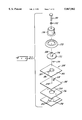
- FIG. 20 is an exploded perspective view, with portions cut away, of a rotary switch having an alternate detent mechanism.
- FIG. 21 is an exploded perspective view of a pushbutton rotary switch.
- FIG. 22 is a section through a rotary switch which includes a blister pack for retaining the armature.
- FIG. 23 is a view similar to FIG. 22 showing an alternate blister pack.
- FIG. 24 is similar to FIGS. 22 and 23, showing a further alternate blister pack.
- FIG. 25 is a section through a rotary switch equipped with an armature retainer.
- FIG. 26 is a bottom plan view of the switch of FIG. 25, with portions cut away to reveal the armature retainer.
- FIG. 27 is a section through a pushbutton rotary switch equipped with an armature retainer.
- FIG. 28 is a perspective view of a V-channel switch.
- FIGS. 1 and 2 illustrate a rotary switch according to the present invention.
- the switch shown generally at 10 includes a substrate layer 12, a non-conductive spacer 14 and a carrier in the form of a membrane layer 16.
- the internal surface of the membrane carries a set of electrodes which define the spaced contacts of at least one electrical switch.
- the electrodes are conventionally formed either by screen printing or etching in copper. These contacts are configured in such a manner as to allow at least two contacts to be shorted together by a metallic armature 18.
- the armature is made of an electrically conductive magnetic material.
- One example would be soft steel plated with silver.
- the silver is added to enhance electrical conductivity and resist oxidation. A harder material such as rhodium could be added to improve wear resistance.
- An opening 20 in the spacer receives the armature 18.
- the armature is a flat, circular disc.
- An actuating knob 22 is mounted for rotation on the switch by a bolt.
- the bolt has a head 23 and a shaft 24 extending through the membrane, spacer opening and substrate.
- a sleeve 25 surrounds the shaft above the membrane.-
- a nut 26 holds the bolt in place.
- a seal ring 28 prevents entry of dirt, dust or moisture into the spacer opening.
- the nut 26 is tightened on shaft 24 to compress the seal ring 28 and sleeve 25 slightly.
- the actuating knob has a central bore that is large enough to permit rotation of the knob on the sleeve.
- the bolt head 23 prevents the knob from coming off the switch.
- the nut is shown as a separate part but alternately its function could be served by a drilled and tapped enlarged portion of the substrate.
- the sleeve 25 could be adhesively bonded to the top of the membrane. In that case the nut would not be needed and the shaft of the bolt would stop short of the membrane.
- the knob 22 carries a coupler 30 in its underside.
- the coupler is a magnet which may be molded or otherwise entrapped in the knob. Where magnetic interference with other electronic components is a concern, the coupler may be shielded as needed.
- the coupler 30 forces the armature 18 against the internal surface of the membrane by means of the magnetic field originating from the coupler.
- the coupler functions both to create the switch contact pressure as well as to drag the armature 18 from one contact to another when a user rotates the knob 22.
- knob could be either in or out of contact with the external surface of the membrane.
- magnet may or may not contact the membrane's external surface.
- Contact, or lack or it, between the knob or magnet and the membrane is not critical so long as the magnet is close enough to the armature to maintain coupling of the magnet and armature, i.e., the armature always moves with the magnet.
- the switch Operation of the switch is as follows.
- the coupler 30 rotates with the knob.
- the armature rotates with the knob.
- the armature moves into shorting contact with the contacts on the membrane, thereby closing the switch. Further rotation will move the armature out of contact with one or both electrodes to open the switch.
- more than one set of switch contacts may be placed under the rotational area of a single knob, providing a plurality of switches under one knob.
- the space traversed by the armature as it rotates with the coupler defines a ring. Toward the inside diameter of that ring may be a circular common contact.
- Toward the outside diameter of the ring may be a plurality of exterior electrodes terminating at a point inside the ring but spaced from each other and the common contact.
- the armature is always in contact with the common contact but moves into and out of contact with the exterior contacts.
- the circular common contact could be a split ring or the like. Numerous variations are possible.
- FIG. 3 illustrates a digital gear 32 which may optionally be incorporated in the rotary switch 10.
- the gear has a hub 34 with a plurality of cogs 36. Four cogs are shown but any number could be included as space permits, the dashed, diagonal lines in FIG. 3 indicating possible additional cog locations.
- the gear would be located on the external surface of the membrane 16, with the hub 34 surrounding the shaft 24 and the sleeve 25 sitting on top of the gear. The sleeve in this case would be shortened by the thickness of the gear 32.
- the underside of the knob 22 would also be cut out to accommodate the gear.
- the gear does not rotate with the knob but instead remains in a fixed position since it is compressed between the sleeve 25 and membrane 16.
- the cogs extend to the inside diameter of the circle described by the rotation of the coupler 30.
- the gear is made of magnetic material so that as the knob rotates the coupler into alignment with a cog the magnetic attraction between the coupler and cog creates a tactile sensation to the user.
- a second magnet carried by the knob could be used in cooperation with the digital gear to provide tactile feedback.
- FIGS. 4 and 5 illustrate a slide switch 38. It has a substrate 40, a spacer 42 with an opening 44, and a carrier in the form of a membrane 46, all similar to the rotary switch 10.
- the opening 44 is an elongated rectangle.
- the internal surface of the carrier or membrane 46 has electrodes or traces 48A, 48B and 48C formed thereon. Electrode 48A is a common electrode while the ends of 48B and 48C are spaced apart as shown. It will be understood that this electrode arrangement is for purposes of illustration only and many variations are possible.
- a plastic housing 50 is mounted on the external surface of the membrane.
- the housing is generally a rectangular box with an elongated slot in the top which receives an actuator or knob 52.
- the actuator carries a coupler 54 which, in a preferred embodiment, is a magnet.
- An armature 56 is disposed in the opening 44.
- the armature may have the same disc-shape as in the rotary switch. Operation of the switch is similar to that of the rotary switch except the motion of the actuator 52 is linear instead of circular.
- the actuator carries the coupler 54 back and forth. Magnetic attraction between the coupler and armature causes the armature to move in conjunction with the coupler, connecting either trace 48B or 48C to trace 48A.
- the slide switch could also have a digital gear for providing a detent as in the rotary switch.
- the coupler magnet is placed off center relative to the armature. This is done intentionally to cause the armature to rotate as the actuator or knob is moved. This extends the life of the switch. While the offset coupler magnet is preferred, it is not necessary to arrange the magnet this way.
- the electrodes shown in the first two embodiments define a switch. They could also be arranged to form a potentiometer.
- a potentiometer can be constructed by replacing the switch contacts with a resistor element to form either a rotary or slide potentiometer.
- FIGS. 6 and 7 illustrate an alternate embodiment of the slide switch. This embodiment is similar to switch 38 except for the armature.
- a cylindrical armature 58 is substituted for the flat, disc-shaped armature.
- the cylindrical armature exhibits no hysteresis, i.e., when the direction of the actuator is reversed, the armature 58 tracks directly with no hesitation.
- the cylindrical armature also minimizes friction between the armature and the conductive traces.
- FIGS. 8-10 illustrate a further alternate embodiment of an armature.
- the armature is a pair of conductive balls 60.
- the balls have all the advantages of the cylindrical armature of FIGS. 6 and 7 plus the following.
- the ball armature will track without either sliding or binding. This will allow for a complex actuating pattern such as the shifting pattern of a five-speed transmission.
- the ball armature configuration could be used in a rotary switch, a slide switch or something having a more complex actuating movement.
- FIG. 10 also illustrates that in its simplest form, the switch of the present invention requires only a carrier with electrodes, a coupler and an armature.
- a spacer and substrate while probably desirable in most applications to protect the armature and electrodes, are not absolutely necessary.
- the carrier is shown as the flexible polyester membrane of a traditional membrane switch, it could be otherwise.
- a printed circuit board could serve as a carrier.
- the carrier need not be a thin, planar sheet. Although this may be the most practical configuration for many applications, any carrier arrangement that transmits enough of the magnetic field so that the armature always tracks with the coupler will suffice.
- FIG. 13 illustrates a variation of the switch having a twin-ball armature.
- this embodiment there are two coupler magnets 54A, 54B with oppositely arranged poles as shown.
- the magnet poles are directly above the balls. While two magnets are shown in the figure, these could be replaced by a single horseshoe magnet or a properly polarized bar magnet.
- the major force component of the magnetic field illustrated by field lines 86, directs the balls up against the switch contacts. This creates a higher contact force and reduces the tendency of the balls to float along a line drawn between the ball centers.
- Another possible variant of the ball armature is to add more balls, perhaps of different sizes, to achieve a multiple contact configuration.
- FIGS. 14 and 15 illustrate a further variant of a slide switch 88. It has a substrate 90, a spacer 92 with an opening 94, and a carrier in the form of a membrane 96, all similar to the rotary switch 38.
- the opening 94 is an elongated rectangle.
- the internal surface of the carrier or membrane 96 has electrodes or traces 98A, 98B and 98C formed thereon. Electrode 98A is a common electrode while the ends of 98B and 98C are spaced apart as shown. It will be understood that this electrode arrangement is for purposes of illustration only and many variations are possible.
- a plastic housing 100 is mounted on the external surface of the membrane.
- the housing is generally a rectangular box with an elongated slot in the top which receives an actuator or knob 102.
- the actuator carries a coupler 104 which, in a preferred embodiment, is a magnet.
- An armature 106 is disposed in the opening 94.
- the armature is an angled piece of magnetic material having faces 108A, 108B joined at a vertex 109. The vertex is always in contact with trace 98A. Operation of the switch is similar to that of the FIG. 4 switch except the armature flips about its vertex rather than sliding.
- the actuator carries the coupler 104 back and forth. Magnetic attraction between the coupler and armature faces 108 causes the armature to flip back and forth, connecting either trace 98B or 98C to trace 98A.
- this armature 106 is the absence of friction between the armature and the switch contacts.
- This type of armature would be used in ultra-long life applications.
- the flipper armature concept could be extended to an armature with more than two faces and thus more than two stable positions to yield a multiple position switch.
- One example of this would be an inverted triangular pyramid or indeed a pyramid with any number of facets on its surface.
- Another extension would be to gang multiple flippers perpendicular to the direction of travel of the actuator. In this case multiple magnets would probably be required depending on the desired switch output.
- FIGS. 11 and 12 illustrate the pushbutton switch 62 according to the present invention.
- the switch 62 includes a substrate 64, a spacer 66 with an opening 68 therein, a layer 70 of a sheet magnet and a membrane 72.
- the membrane could be deleted, although it is preferred to have a membrane to seal against dust, dirt and liquids as well as to provide a surface for graphics to be printed.
- the membrane is normally embossed as at 74 to provide space for the actuating button 76 formed on armature 78. This space could also be made by placing a second spacer in between the top surface of magnetic layer 70 and the underside of the membrane 72.
- the armature 78 is located primarily within spacer opening 68. Its actuating button 76 protrudes through an aperture 80 in the magnetic layer 70.
- the lower surface of the armature has a fulcrum. In this case the fulcrum takes the form of a pair of extensions 82. The extensions are shown spaced from the electrode 84A but they could be in contact even when the switch is open.
- the armature is made of electrically conductive and magnetic material.
- the magnetic layer 70 holds the armature 78 up against the underside of the layer. Electrodes 84A, 84B are formed on the internal surface of the substrate.
- the user will press the actuating button 76.
- pre-travel is achieved when the membrane is first deformed.
- the armature abruptly breaks away from the magnetic sheet material thus providing a very crisp tactile sensation.
- the fulcrum extensions 82 will snap loose from magnetic layer 70 and engage electrode 84A. Thereafter the armature will pivot about the fulcrum and into contact with the electrode 84B. This shorts the electrodes and closes the switch.
- the magnetic attraction between layer 70 and the armature 78 will return the armature to the position of FIG. 12, thereby reopening the switch. Since the button 78 extends through aperture 80, the magnetic layer 70 moves very little, if at all during closure.
- Improved tactile feel can be achieved by placing a ferro-magnetic material on the top surface of the magnet sheet layer 70.
- This material has the effect of directing the magnetic field downwardly toward the armature. This material further enhances the tactile sensation by providing rigidity to the magnetic sheet material.
- a ferro-magnetic material is placed on the top surface of the magnet sheet layer 70.
- This material has the effect of directing the magnetic field downwardly toward the armature.
- This material further enhances the tactile sensation by providing rigidity to the magnetic sheet material.
- One example of such a material would be a thin soft steel sheet.
- the pushbutton switch as shown and described can be afforded a custom tactile feel by changing the position and size of the actuating button. Increased switch travel and/or overtravel can be achieved by adjusting the geometry and size of the armature. Ultra-short switch travel can be achieved by adjusting the position of the actuating button. Stand-alone, individual, discrete switches can be fabricated. The magnetic return force allows switches to be held in the actuated position for extended periods without becoming permanently actuated. Backlighting can be achieved by providing a hole in the armature. High temperature manufacturing processes including wave soldering can be used with high temperature materials. A printed circuit board could be used as a substrate. If an extra set of electrical contacts were located under the magnetic layer 70 (either on the layer 70 or on a membrane under the layer 70) a normally-closed switch could be incorporated in the switch of FIGS. 11 and 12.
- FIGS. 16 and 17 An alternate form of pushbutton switch is shown at 110 in FIGS. 16 and 17. This is a bi-stable rocker switch.
- the switch 110 has a membrane 112 disposed on top of a spacer 114.
- a substrate 116 lies on the side of the spacer opposite the membrane.
- a plastic backing plate 118 is situated beneath the substrate 116.
- the internal surface of the substrate 116 has electrodes or traces 120A, 120B and 120C formed thereon which terminate at circular pads as shown in FIG. 16.
- Electrode 120B is a common electrode.
- An opening 122 in the spacer 114 receives a rocking armature 124.
- the armature 124 is made of magnetic material and has a pair of arms 126A, 126B extending in opposite directions from a central fulcrum 128.
- the armature pivots or rocks in the spacer opening 122 about the fulcrum 128 in seesaw fashion.
- the fulcrum rests on the pad of common electrode 120B.
- the arms 126A, 126B extend toward the pads of electrodes 120A and 120C.
- the arm 126B is shown in FIG. 17 in the actuated position wherein the arm is in contact with electrode 120C.
- a pair of magnets 130, 132 are embedded in the backing plate 118 beneath the substrate. The magnets retain the armature in an actuated position and provide a tactile sensation when the switch is operated.
- the arm 126B of armature 124 breaks contact with electrode 120C and opens the right switch.
- arm 126A makes contact with electrode 120A, closing the left switch formed by electrodes 120A and 120B.
- the pushbutton switch of FIGS. 16 and 17 can also be tri-stable or multi-stable depending on the shape of the armature and the switch contact configuration. In a tri-stable configuration and beyond, the armature would take the shape of an inverted pyramid. A further alternate embodiment of this switch would involve deletion of one of the magnets 130 or 132. Such a switch could be termed mono-stable because the armature would always be in contact with the electrode above the remaining magnet except when a user is depressing another part of the membrane. When that pressure is released, the magnet would cause the armature to revert to its closed position. Thus, the switch would be normally-closed.
- FIG. 18 illustrates a rotary switch 134 having a pre-load mechanism.
- the coupler magnet is used to create a drag or pre-load on the actuating knob.
- the switch 134 includes a backing plate 136 and a membrane layer 138.
- the underside of the membrane carries a set of electrodes which define the electrical switch or potentiometer.
- a metallic armature 140 is situated in an opening 142 in the backing plate 136.
- an actuator plate 144 Located just above the membrane 138 is an actuator plate 144 which rotates with shaft 146 when a user turns an actuating knob 148.
- the shaft 146 is mounted for rotation in a plastic housing 150.
- a lock nut 151 retains the shaft in place.
- the lock nut also fastens a dial 153 which may be optionally placed on top of the housing 150.
- a ferromagnetic pre-load plate 152 rests between the underside of the housing 150 and the actuator plate 144.
- the plate 144 carries a coupler 154, which is a magnet similar to the coupler 30.
- the coupler not only moves the armature 140 to make and break the switch but also engages the pre-load plate 152.
- As the actuator plate rotates the friction between the pre-load plate and the coupler provides increased rotational torque. This arrangement could also be incorporated in a slide switch of the type shown in FIGS. 4 and 5.
- FIG. 19 illustrates an alternate detent mechanism that could be incorporated in either a slide switch or a rotary switch.
- the particular embodiment shown is a slide switch.
- a floating detent plate 156 has a series of depressions or valleys 158 along one edge.
- the detent plate is constrained from longitudinal motion but is able to flex laterally to allow passage of a protrusion or bump 160 on the side edge of the actuator 162.
- the switch-actuating magnet 164 in the actuator provides the attractive force between the armature and actuator and between the detent plate 156 and the actuator. As the bump 160 slides into and out of the valleys 158 a distinct snap action is created which the user can easily feel, thereby indicating the making or breaking of the switch contacts.
- FIG. 20 illustrates a further alternate detent mechanism that could be incorporated in either a slide switch or a rotary switch.
- the particular embodiment shown is a rotary switch.
- the switch includes a carrier in the form of a membrane layer 166.
- the underside of the carrier has a set of electrodes which define the spaced contacts of at least one electrical switch or potentiometer.
- a twin-ball armature 168 rides on the underside of the carrier 166.
- the armature moves with a coupler magnet 170 which is mounted in a rotor 172.
- the rotor has an upstanding post 174 on which a knob 176 is mounted for manipulating the rotor.
- the rotor is mounted for rotation on the carrier 166 by a bracket 178.
- a detent plate 180 Located just above the rotor is a detent plate 180.
- the plate is made of magnetic material and has a series of ribs 182. Each rib defines a detent position as it aligns with the coupler magnet 170.
- the plate 180 is held fixed by the bracket 178. As the knob rotates the coupler into alignment with a rib the magnetic attraction between the coupler and rib creates a tactile sensation to the user.
- the ribs can be located in any position.
- the detent shown is designed for a 32-position quadrature output rotary switch.
- a pushbutton rotary switch or potentiometer as seen in FIG. 21, is applicable to situations where a user would like to change ranges or expand the scale in some manner as the user is turning or sliding a knob. This is normally done by pushing either the knob or pushing a button located on the top surface of the knob.
- FIG. 21 shows how this concept can be applied in the present invention.
- the pushbutton rotary potentiometer 184 has several parts in common with the switch of FIG. 20, including carrier layer 166, twin-ball armature 168, coupler magnet 170, rotor 172 with post 174, knob 176 and mounting bracket 178.
- the underside of the carrier 166 has a set of electrodes or contacts which define the spaced contacts of at least one electrical switch or, as shown here, a potentiometer. There is a common contact 186 and a surrounding resistive element 187.
- the armature 168 engages the electrodes on the underside of the carrier 166, moving with the coupler magnet 170 as it turns with the rotor 172.
- the post 174 and knob 176 have a central bore 188 through which a pushbutton 190 extends.
- the pushbutton is retained by a spring washer 192.
- the pushbutton 190 bottoms on the carrier 166. Beneath the carrier is a membrane switch comprising a flexible membrane 194, a spacer 196, and a substrate 198.
- the spacer has an opening 200. Spaced apart electrodes or contacts 202 are formed on the upper side of the substrate. A shorting contact or pad 204 is formed on the underside of the membrane 194. When a user depresses the pushbutton 190 it pushes the membrane 194 down through the spacer opening 200 to a point where pad 204 engages contacts 202, thus closing the pushbutton switch.
- the pushbutton rotary switch include locating an actuating pin on the base of the rotor. In this case the entire knob 176 is depressed to push the membrane 194 through the spacer 196 and close the contacts-202. It may also be possible to locate the membrane switch on the same side of the carrier as the rotor and knob.
- a further alternative form of the switch permits deletion of the membrane layer 194.
- the carrier layer 166 is made of flexible material and contacts are arranged on its lower surface that form both the rotary switch and a shorting contact for the pushbutton switch.
- the rotary switch 206 of FIG. 22 is similar to the switch of FIG. 20, including a carrier layer 166, a twin-ball armature 168, a coupler magnet 170, a rotor 172 with post 174, a knob 176 and a mounting bracket 178.
- the underside of the carrier 166 has a set of electrodes or contacts which define the spaced contacts of at least one electrical switch or potentiometer.
- the armature 168 engages these electrodes, moving with the coupler magnet 170 as it turns with the rotor 172.
- the armature is protected by a dome member, in this case a blister pack backer plate 208.
- Plate 208 is a film layer adhesively or otherwise secured to the underside of the carrier 166.
- a blister 210 is formed by embossing the film to provide a chamber 212 within which the armature 168 can float. Should the armature somehow become displaced, it is contained within the blister chamber 212 and thus the armature remains in the immediate vicinity of the magnets located in the rotor 172. The armature will be returned to its seated position either spontaneously after the dislodging force is removed, or when the rotor is again moved over the loose armature located inside the blister.
- FIG. 23 An alternate dome member is shown in FIG. 23.
- a back cover 214 is molded as an individual plastic part. Hooks 216 are provided on the bracket 178A to mate with slots 218 in the cover 214 so the two parts snap together. Holes in the carrier may be needed to allow the hooks to pass through.
- the cover 214 has a central boss 220 which defines a circular raceway or track 222 in which the balls 168 move.
- a further alternate dome member is shown in FIG. 24.
- a back cover 224 defines a chamber 226 for retaining the armature. Either one or both of the bracket 178B and the back cover 224 could be made of a ferro-magnetic metal to provide magnetic shielding to the outside world, as well as to take advantage of the economics of using a stamped metal part.
- FIGS. 25 and 26 A variation of the dome armature protectors is shown in FIGS. 25 and 26.
- This version has a mounting bracket similar to bracket 178A in that it has hooks 216 for holding a cover 228.
- Cover 228 defines an open chamber 230 between it and the carrier 166.
- a ball retainer 232 fits in the chamber. The balls 168 are held in position by the retainer. Even if a mechanical impulse causes the balls to break contact, they are immediately reseated after the impulse is removed.
- the ball retainer is designed to move with the balls during either rotary motion or sliding motion. It might also be possible to use the retainer 232 without the cover 228 if the edges of the retainer were slotted into the hooks to hold it in position.
- FIG. 27 shows an alternate arrangement of a retainer incorporated in a pushbutton rotary switch.
- This switch has a cover 234 attached to a flexible carrier layer 236.
- the underside of the carrier has silver contacts 238.
- a rotor 240 has two couplers in the form of magnet pairs 242.
- the rotor also has a hollow central post 244.
- the rotor is attached to a knob 246 by an E-ring 248.
- a plunger 250 can move up and down in the bore of the post 244.
- the plunger is shown resting on top of the carrier 236. Alternately there may be an opening in the carrier allowing the plunger to extend through into contact with a retainer hub 258.
- Two twin-ball armatures 252 are fixed in receptacles 254 of a ball retainer.
- the retainer includes a web 256 joining the receptacles to a central hub 258.
- the hub is aligned with the plunger 250 and directly above the contacts of a membrane switch.
- the membrane switch includes a membrane 260, spacer 262 and substrate 264, with facing contacts 266 on the inside surfaces of the membrane and substrate. Pressure on the top of the plunger 250 is transferred by the hub 258 to the membrane, pushing it through an opening in the spacer to bring contacts 264 into engagement.
- the hub may alternately include a small button or nodule on its underside to further concentrate the actuating force.
- FIG. 28 shows a V-channel ball armature device. As with the other devices shown herein this could be either a switch or potentiometer, depending on the arrangement of the electrodes.
- the device includes a carrier block 268 having a V-shaped channel 270 or groove in one surface. There are electrodes 272 formed on the sloped sides of the channel.
- a single ball armature 274 rides in the channel.
- a coupler 276 is movable on the carrier block side opposite the channel for the purpose of moving the ball 274 back and forth in the channel. This arrangement permits a single ball armature.
- the channel could have a devious path with corners or curves to define a complex actuating pattern, e.g., the shifting pattern of a five-speed transmission.
Abstract
Description
Claims (16)
Priority Applications (9)
| Application Number | Priority Date | Filing Date | Title |
|---|---|---|---|
| US08/924,334 US5867082A (en) | 1995-06-02 | 1997-09-05 | Switch with magnetically-coupled armature |
| DE69835361T DE69835361T2 (en) | 1997-09-05 | 1998-09-03 | SWITCH WITH MAGNETIC COUPLED ANCHOR |
| EP98945854A EP1010189B1 (en) | 1997-09-05 | 1998-09-03 | Switch with magnetically-coupled armature |
| AU93004/98A AU727962B2 (en) | 1997-09-05 | 1998-09-03 | Switch with magnetically-coupled armature |
| CN98810707.4A CN1129158C (en) | 1997-09-05 | 1998-09-03 | Switch with magnetically-coupled armature |
| CA002303190A CA2303190C (en) | 1997-09-05 | 1998-09-03 | Switch with magnetically-coupled armature |
| PCT/US1998/018293 WO1999013481A1 (en) | 1997-09-05 | 1998-09-03 | Switch with magnetically-coupled armature |
| US09/160,645 US5990772A (en) | 1995-06-02 | 1998-09-25 | Pushbutton switch with magnetically coupled armature |
| US09/396,904 US6130593A (en) | 1995-06-02 | 1999-09-15 | Switch panel having a magnetically-retained overlay |
Applications Claiming Priority (3)
| Application Number | Priority Date | Filing Date | Title |
|---|---|---|---|
| US08458989 US5523730C1 (en) | 1995-06-02 | 1995-06-02 | Switch with mangnetically-coupled armature |
| US08/646,083 US5666096A (en) | 1995-06-02 | 1996-05-07 | Switch with magnetically-coupled armature |
| US08/924,334 US5867082A (en) | 1995-06-02 | 1997-09-05 | Switch with magnetically-coupled armature |
Related Parent Applications (1)
| Application Number | Title | Priority Date | Filing Date |
|---|---|---|---|
| US08/646,083 Continuation-In-Part US5666096A (en) | 1995-06-02 | 1996-05-07 | Switch with magnetically-coupled armature |
Related Child Applications (1)
| Application Number | Title | Priority Date | Filing Date |
|---|---|---|---|
| US09/160,645 Continuation-In-Part US5990772A (en) | 1995-06-02 | 1998-09-25 | Pushbutton switch with magnetically coupled armature |
Publications (1)
| Publication Number | Publication Date |
|---|---|
| US5867082A true US5867082A (en) | 1999-02-02 |
Family
ID=25450093
Family Applications (1)
| Application Number | Title | Priority Date | Filing Date |
|---|---|---|---|
| US08/924,334 Expired - Lifetime US5867082A (en) | 1995-06-02 | 1997-09-05 | Switch with magnetically-coupled armature |
Country Status (7)
| Country | Link |
|---|---|
| US (1) | US5867082A (en) |
| EP (1) | EP1010189B1 (en) |
| CN (1) | CN1129158C (en) |
| AU (1) | AU727962B2 (en) |
| CA (1) | CA2303190C (en) |
| DE (1) | DE69835361T2 (en) |
| WO (1) | WO1999013481A1 (en) |
Cited By (74)
| Publication number | Priority date | Publication date | Assignee | Title |
|---|---|---|---|---|
| US5977873A (en) * | 1998-03-04 | 1999-11-02 | Woods; Randall | Alarm switch |
| US5990772A (en) * | 1995-06-02 | 1999-11-23 | Duraswitch Industries, Inc. | Pushbutton switch with magnetically coupled armature |
| US6023213A (en) * | 1999-08-11 | 2000-02-08 | Duraswitch Industries, Inc. | Relocatable knob retention for magnetically actuated switch |
| US6186392B1 (en) * | 2000-01-21 | 2001-02-13 | Micron Technology, Inc. | Method and system for forming contacts on a semiconductor component by aligning and attaching ferromagnetic balls |
| WO2001075920A1 (en) * | 2000-03-30 | 2001-10-11 | Duraswitch Industries, Inc. | Method and kit for converting a flat panel switch |
| EP1347481A1 (en) * | 2002-03-22 | 2003-09-24 | Matsushita Electric Industrial Co., Ltd. | Rotary manipulation type input device and electronic apparatus using the same |
| US6677843B1 (en) * | 2003-06-06 | 2004-01-13 | Datahand Systems, Inc. | Magnetically coupled pushbutton plunger switch |
| US20040245080A1 (en) * | 2003-06-03 | 2004-12-09 | William Turner | Multi-functional control assembly for use in electric guitars |
| US6943705B1 (en) | 2002-05-03 | 2005-09-13 | Synaptics, Inc. | Method and apparatus for providing an integrated membrane switch and capacitive sensor |
| US20050264891A1 (en) * | 2004-06-01 | 2005-12-01 | Uken John T | Mirror assembly for vehicle |
| US20060047271A1 (en) * | 2004-08-31 | 2006-03-02 | Medtronic, Inc. | Surgical apparatus including a hand-activated, cable assembly and method of using same |
| US20060047272A1 (en) * | 2004-08-31 | 2006-03-02 | Medtronic, Inc. | Surgical apparatus including a hand-activated, control assembly and method of using same |
| US20060076153A1 (en) * | 2002-12-19 | 2006-04-13 | Ferdinand Kristen | Electrical hand-held power tool with non-contacting electrical manual control switch |
| US20060243122A1 (en) * | 2005-05-02 | 2006-11-02 | James Carson | Musical instrument mounting adapter |
| US20070024408A1 (en) * | 2005-07-29 | 2007-02-01 | Homeease Industrial Co., Ltd. | Adjustable temperature switch |
| US20070153073A1 (en) * | 2005-12-29 | 2007-07-05 | Tracy Kucaba | Pad mounting for a pad printer |
| US20070284233A1 (en) * | 2006-06-09 | 2007-12-13 | Kabushiki Kaisha Tokai Rika Denki Seisakusho | Switch device |
| US20080023229A1 (en) * | 2006-05-16 | 2008-01-31 | Schlumberger Technology Corporation | Tri stable actuator apparatus and method |
| CN100394523C (en) * | 2004-06-16 | 2008-06-11 | 阿尔卑斯电气株式会社 | Composite inputting device |
| US20080164970A1 (en) * | 2005-06-30 | 2008-07-10 | Spectra Symbol Corp. | Contactless Magnetic Potentiometer |
| WO2008145404A2 (en) * | 2007-05-31 | 2008-12-04 | Valeo Klimasysteme Gmbh | Magnetically actuated electric switch |
| US20090015360A1 (en) * | 2007-03-12 | 2009-01-15 | Touchsensor Technologies, Llc | Haptic feedback system and method |
| US20090026054A1 (en) * | 2007-07-25 | 2009-01-29 | Roland Lee | Trigger Arrangement with Feedback Response |
| US20090259790A1 (en) * | 2008-04-15 | 2009-10-15 | Razer (Asia-Pacific) Pte Ltd | Ergonomic slider-based selector |
| US20100059348A1 (en) * | 2006-10-30 | 2010-03-11 | Ronald Hauf | Actuating element |
| EP2169226A2 (en) * | 2002-02-20 | 2010-03-31 | Terumo Cardiovascular Systems Corporation | Magnetic detent for rotatable knob |
| US20100091394A1 (en) * | 2008-10-14 | 2010-04-15 | Magna Mirrors Of America, Inc. | Interior rearview mirror assembly with button module |
| US20110025451A1 (en) * | 2009-07-29 | 2011-02-03 | Marriott Daniel F | Magnetically-Activated Membrane Potentiometer |
| US20120182101A1 (en) * | 2009-09-30 | 2012-07-19 | Nec Corporation | Analog pointing key structure |
| US8284015B1 (en) * | 2009-09-03 | 2012-10-09 | Van Eyck Jerry J | Easily sanitized control device |
| US8309870B2 (en) | 2011-01-04 | 2012-11-13 | Cody George Peterson | Leveled touchsurface with planar translational responsiveness to vertical travel |
| US20140167890A1 (en) * | 2012-12-19 | 2014-06-19 | C&K Components S.A.S. | Electrical switch arrangement and device for controlling an apparatus comprising such an arrangement |
| US8912458B2 (en) | 2011-01-04 | 2014-12-16 | Synaptics Incorporated | Touchsurface with level and planar translational travel responsiveness |
| US9040851B2 (en) | 2012-08-06 | 2015-05-26 | Synaptics Incorporated | Keycap assembly with an interactive spring mechanism |
| ES2537605A1 (en) * | 2015-03-03 | 2015-06-10 | Seat, S.A. | Actuator device for control unit and control procedure of an actuator device for control unit (Machine-translation by Google Translate, not legally binding) |
| US9177733B2 (en) | 2012-08-06 | 2015-11-03 | Synaptics Incorporated | Touchsurface assemblies with linkages |
| US9213372B2 (en) | 2013-04-19 | 2015-12-15 | Synaptics Incorporated | Retractable keyboard keys |
| US9218927B2 (en) | 2012-08-06 | 2015-12-22 | Synaptics Incorporated | Touchsurface assembly with level and planar translational responsiveness via a buckling elastic component |
| US9224554B2 (en) | 2013-03-14 | 2015-12-29 | Synaptics Incorporated | Anti-tilt and rotation techniques for a touchsurface assembly having translating keys |
| US20160069712A1 (en) * | 2014-09-09 | 2016-03-10 | Apple Inc. | Magnetically Coupled Optical Encoder |
| US9324515B2 (en) | 2012-08-06 | 2016-04-26 | Synaptics Incorporated | Touchsurface assembly utilizing magnetically enabled hinge |
| US20160320793A1 (en) * | 2015-04-29 | 2016-11-03 | Advanced Input Devices, Inc. | Magnetic detenting configuration for custom encoder |
| US9709956B1 (en) | 2013-08-09 | 2017-07-18 | Apple Inc. | Tactile switch for an electronic device |
| US9753436B2 (en) | 2013-06-11 | 2017-09-05 | Apple Inc. | Rotary input mechanism for an electronic device |
| US9891651B2 (en) | 2016-02-27 | 2018-02-13 | Apple Inc. | Rotatable input mechanism having adjustable output |
| US9952558B2 (en) | 2015-03-08 | 2018-04-24 | Apple Inc. | Compressible seal for rotatable and translatable input mechanisms |
| US10019097B2 (en) | 2016-07-25 | 2018-07-10 | Apple Inc. | Force-detecting input structure |
| US10018966B2 (en) | 2015-04-24 | 2018-07-10 | Apple Inc. | Cover member for an input mechanism of an electronic device |
| US10048802B2 (en) | 2014-02-12 | 2018-08-14 | Apple Inc. | Rejection of false turns of rotary inputs for electronic devices |
| US10061399B2 (en) | 2016-07-15 | 2018-08-28 | Apple Inc. | Capacitive gap sensor ring for an input device |
| US20180308649A1 (en) * | 2017-04-19 | 2018-10-25 | Danfoss Power Solutions, Inc. | Rotary knob controller |
| US10145712B2 (en) | 2014-09-09 | 2018-12-04 | Apple Inc. | Optical encoder including diffuser members |
| US10145711B2 (en) | 2015-03-05 | 2018-12-04 | Apple Inc. | Optical encoder with direction-dependent optical properties having an optically anisotropic region to produce a first and a second light distribution |
| US10190891B1 (en) | 2014-07-16 | 2019-01-29 | Apple Inc. | Optical encoder for detecting rotational and axial movement |
| US10203662B1 (en) | 2017-09-25 | 2019-02-12 | Apple Inc. | Optical position sensor for a crown |
| US10302465B2 (en) | 2015-03-06 | 2019-05-28 | Apple Inc. | Dynamic adjustment of a sampling rate for an optical encoder |
| US10394325B2 (en) | 2013-12-10 | 2019-08-27 | Apple Inc. | Input friction mechanism for rotary inputs of electronic devices |
| US10503271B2 (en) | 2015-09-30 | 2019-12-10 | Apple Inc. | Proximity detection for an input mechanism of an electronic device |
| US10551798B1 (en) | 2016-05-17 | 2020-02-04 | Apple Inc. | Rotatable crown for an electronic device |
| US10592008B1 (en) | 2017-09-05 | 2020-03-17 | Apple Inc. | Mouse having a shape-changing enclosure |
| US10599101B2 (en) | 2014-09-02 | 2020-03-24 | Apple Inc. | Wearable electronic device |
| US10664074B2 (en) | 2017-06-19 | 2020-05-26 | Apple Inc. | Contact-sensitive crown for an electronic watch |
| US10946389B2 (en) * | 2017-12-05 | 2021-03-16 | Vorwerk & Co. Interholding Gmbh | Activation device with magnets |
| US10962935B1 (en) | 2017-07-18 | 2021-03-30 | Apple Inc. | Tri-axis force sensor |
| US11181863B2 (en) | 2018-08-24 | 2021-11-23 | Apple Inc. | Conductive cap for watch crown |
| US11194298B2 (en) | 2018-08-30 | 2021-12-07 | Apple Inc. | Crown assembly for an electronic watch |
| US11194299B1 (en) | 2019-02-12 | 2021-12-07 | Apple Inc. | Variable frictional feedback device for a digital crown of an electronic watch |
| US11269376B2 (en) | 2020-06-11 | 2022-03-08 | Apple Inc. | Electronic device |
| US11360440B2 (en) | 2018-06-25 | 2022-06-14 | Apple Inc. | Crown for an electronic watch |
| US11550268B2 (en) | 2020-06-02 | 2023-01-10 | Apple Inc. | Switch module for electronic crown assembly |
| US11561515B2 (en) | 2018-08-02 | 2023-01-24 | Apple Inc. | Crown for an electronic watch |
| US11747919B1 (en) * | 2021-05-14 | 2023-09-05 | Apple Inc. | Multi-input for rotating and translating crown modules |
| US11796961B2 (en) | 2018-08-24 | 2023-10-24 | Apple Inc. | Conductive cap for watch crown |
| US11796968B2 (en) | 2018-08-30 | 2023-10-24 | Apple Inc. | Crown assembly for an electronic watch |
Families Citing this family (4)
| Publication number | Priority date | Publication date | Assignee | Title |
|---|---|---|---|---|
| US6069552A (en) * | 1999-06-02 | 2000-05-30 | Duraswitch Industries, Inc. | Directionally sensitive switch |
| KR101628396B1 (en) * | 2010-11-26 | 2016-06-08 | 현대자동차주식회사 | haptic scroll wheel device |
| CN105161341B (en) * | 2015-08-12 | 2017-06-16 | 珠海市智迪科技股份有限公司 | A kind of magnetic suspension button and keyboard |
| CN110730998B (en) * | 2017-06-20 | 2021-11-19 | 株式会社藤仓 | Switch with a switch body |
Citations (29)
| Publication number | Priority date | Publication date | Assignee | Title |
|---|---|---|---|---|
| US2410746A (en) * | 1942-09-02 | 1946-11-05 | Adele S Raettig | Magnetically operated switch |
| DE1055646B (en) * | 1955-12-22 | 1959-04-23 | Siemens Ag | Magnetic coupling arrangement for transmitting the switching force for electrical switches through a non-magnetic partition |
| DE1144368B (en) * | 1959-02-07 | 1963-02-28 | Telefonbau | Arrangement for opening or closing electrical circuits |
| FR1329674A (en) * | 1962-05-02 | 1963-06-14 | Magnetic contactor | |
| US3735300A (en) * | 1971-05-10 | 1973-05-22 | Webb Int Co Jervis B | Magnetic coding device for moving bodies such as conveyor carriers |
| US3859612A (en) * | 1973-04-03 | 1975-01-07 | Casio Computer Co Ltd | Switching device |
| US3879602A (en) * | 1973-06-11 | 1975-04-22 | N Dimensions | Keyboard |
| US4068202A (en) * | 1976-06-07 | 1978-01-10 | Walter F. Wessendorf, Jr. | Reciprocable magnet switch |
| US4101857A (en) * | 1976-09-30 | 1978-07-18 | Toole Lawrence P O | Externally-programable switch |
| US4199741A (en) * | 1976-11-05 | 1980-04-22 | Edouard Serrus Paulet | Moving magnet, rotary switch |
| US4203013A (en) * | 1976-10-26 | 1980-05-13 | Serras Paulet Edouard | Alphanumeric control keyboard with depressible keys for electric or electronic machines |
| US4370631A (en) * | 1981-01-22 | 1983-01-25 | The United States Of America As Represented By The Secretary Of The Navy | Waveguide switch |
| US4389627A (en) * | 1980-11-19 | 1983-06-21 | Chino Works, Ltd. | Changeover switch for actuating a plurality of reed switches disposed in a circle |
| US4400594A (en) * | 1978-11-29 | 1983-08-23 | Serras Paulet Edouard | Control keyboard for electric or electronic devices |
| DE3408599A1 (en) * | 1984-03-09 | 1985-09-19 | MIT Wilde Membran Impuls Technik GmbH, 5828 Ennepetal | Component for switching technology |
| US4603309A (en) * | 1984-05-25 | 1986-07-29 | Honeywell Inc. | Switching high speed digital pulses |
| US4669486A (en) * | 1984-01-20 | 1987-06-02 | Anders Trell | Device for taking and dispensing blood samples for the purpose of determining blood sedimentation |
| US4916275A (en) * | 1988-04-13 | 1990-04-10 | Square D Company | Tactile membrane switch assembly |
| DE9003955U1 (en) * | 1990-04-05 | 1990-06-13 | Westra Electronic Gmbh, 8901 Welden, De | |
| US4972052A (en) * | 1986-11-17 | 1990-11-20 | Autoliv Development Ab | Contact device for delivering electrical signals corresponding to the position of a movable body |
| US5144274A (en) * | 1989-11-28 | 1992-09-01 | Ken Hayashibara | Sealed variable resistor |
| US5268660A (en) * | 1990-05-29 | 1993-12-07 | Cappelli Guido G | Quadrant driver for microwave switches |
| US5313027A (en) * | 1992-03-16 | 1994-05-17 | Matsushita Electric Industrial Co., Ltd. | Push button switch assembly including single or plural sequentially closed switches |
| US5332992A (en) * | 1993-04-06 | 1994-07-26 | Randall Woods | Security alarm switch |
| US5365155A (en) * | 1990-10-22 | 1994-11-15 | Marquardt Gmbh | Rotational speed control and use of same to control the rotational speed of an electric hand tool motor |
| US5510589A (en) * | 1994-02-28 | 1996-04-23 | Intermec Corporation | High-life sealed switch assembly with tactile feedback |
| US5523730A (en) * | 1995-06-02 | 1996-06-04 | Van Zeeland; Anthony J. | Switch with mangnetically-coupled armature |
| US5666096A (en) * | 1995-06-02 | 1997-09-09 | Van Zeeland; Anthony J. | Switch with magnetically-coupled armature |
| US5717176A (en) * | 1996-07-17 | 1998-02-10 | United Technologies Automotive, Inc. | Sequentially operated membrane switches |
-
1997
- 1997-09-05 US US08/924,334 patent/US5867082A/en not_active Expired - Lifetime
-
1998
- 1998-09-03 CN CN98810707.4A patent/CN1129158C/en not_active Expired - Fee Related
- 1998-09-03 WO PCT/US1998/018293 patent/WO1999013481A1/en active IP Right Grant
- 1998-09-03 EP EP98945854A patent/EP1010189B1/en not_active Expired - Lifetime
- 1998-09-03 DE DE69835361T patent/DE69835361T2/en not_active Expired - Lifetime
- 1998-09-03 AU AU93004/98A patent/AU727962B2/en not_active Ceased
- 1998-09-03 CA CA002303190A patent/CA2303190C/en not_active Expired - Fee Related
Patent Citations (30)
| Publication number | Priority date | Publication date | Assignee | Title |
|---|---|---|---|---|
| US2410746A (en) * | 1942-09-02 | 1946-11-05 | Adele S Raettig | Magnetically operated switch |
| DE1055646B (en) * | 1955-12-22 | 1959-04-23 | Siemens Ag | Magnetic coupling arrangement for transmitting the switching force for electrical switches through a non-magnetic partition |
| DE1144368B (en) * | 1959-02-07 | 1963-02-28 | Telefonbau | Arrangement for opening or closing electrical circuits |
| FR1329674A (en) * | 1962-05-02 | 1963-06-14 | Magnetic contactor | |
| US3735300A (en) * | 1971-05-10 | 1973-05-22 | Webb Int Co Jervis B | Magnetic coding device for moving bodies such as conveyor carriers |
| US3859612A (en) * | 1973-04-03 | 1975-01-07 | Casio Computer Co Ltd | Switching device |
| US3879602A (en) * | 1973-06-11 | 1975-04-22 | N Dimensions | Keyboard |
| US4068202A (en) * | 1976-06-07 | 1978-01-10 | Walter F. Wessendorf, Jr. | Reciprocable magnet switch |
| US4101857A (en) * | 1976-09-30 | 1978-07-18 | Toole Lawrence P O | Externally-programable switch |
| US4203013A (en) * | 1976-10-26 | 1980-05-13 | Serras Paulet Edouard | Alphanumeric control keyboard with depressible keys for electric or electronic machines |
| US4199741A (en) * | 1976-11-05 | 1980-04-22 | Edouard Serrus Paulet | Moving magnet, rotary switch |
| US4400594A (en) * | 1978-11-29 | 1983-08-23 | Serras Paulet Edouard | Control keyboard for electric or electronic devices |
| US4389627A (en) * | 1980-11-19 | 1983-06-21 | Chino Works, Ltd. | Changeover switch for actuating a plurality of reed switches disposed in a circle |
| US4370631A (en) * | 1981-01-22 | 1983-01-25 | The United States Of America As Represented By The Secretary Of The Navy | Waveguide switch |
| US4669486A (en) * | 1984-01-20 | 1987-06-02 | Anders Trell | Device for taking and dispensing blood samples for the purpose of determining blood sedimentation |
| DE3408599A1 (en) * | 1984-03-09 | 1985-09-19 | MIT Wilde Membran Impuls Technik GmbH, 5828 Ennepetal | Component for switching technology |
| US4603309A (en) * | 1984-05-25 | 1986-07-29 | Honeywell Inc. | Switching high speed digital pulses |
| US4972052A (en) * | 1986-11-17 | 1990-11-20 | Autoliv Development Ab | Contact device for delivering electrical signals corresponding to the position of a movable body |
| US4916275A (en) * | 1988-04-13 | 1990-04-10 | Square D Company | Tactile membrane switch assembly |
| US5144274A (en) * | 1989-11-28 | 1992-09-01 | Ken Hayashibara | Sealed variable resistor |
| DE9003955U1 (en) * | 1990-04-05 | 1990-06-13 | Westra Electronic Gmbh, 8901 Welden, De | |
| US5268660A (en) * | 1990-05-29 | 1993-12-07 | Cappelli Guido G | Quadrant driver for microwave switches |
| US5365155A (en) * | 1990-10-22 | 1994-11-15 | Marquardt Gmbh | Rotational speed control and use of same to control the rotational speed of an electric hand tool motor |
| US5313027A (en) * | 1992-03-16 | 1994-05-17 | Matsushita Electric Industrial Co., Ltd. | Push button switch assembly including single or plural sequentially closed switches |
| US5332992A (en) * | 1993-04-06 | 1994-07-26 | Randall Woods | Security alarm switch |
| US5510589A (en) * | 1994-02-28 | 1996-04-23 | Intermec Corporation | High-life sealed switch assembly with tactile feedback |
| US5523730A (en) * | 1995-06-02 | 1996-06-04 | Van Zeeland; Anthony J. | Switch with mangnetically-coupled armature |
| US5666096A (en) * | 1995-06-02 | 1997-09-09 | Van Zeeland; Anthony J. | Switch with magnetically-coupled armature |
| US5523730C1 (en) * | 1995-06-02 | 2002-01-15 | Van Anthony J Zeeland | Switch with mangnetically-coupled armature |
| US5717176A (en) * | 1996-07-17 | 1998-02-10 | United Technologies Automotive, Inc. | Sequentially operated membrane switches |
Cited By (156)
| Publication number | Priority date | Publication date | Assignee | Title |
|---|---|---|---|---|
| US5990772A (en) * | 1995-06-02 | 1999-11-23 | Duraswitch Industries, Inc. | Pushbutton switch with magnetically coupled armature |
| US5977873A (en) * | 1998-03-04 | 1999-11-02 | Woods; Randall | Alarm switch |
| USRE39731E1 (en) * | 1998-03-04 | 2007-07-17 | Magnasphere Corporation | Alarm switch |
| US6023213A (en) * | 1999-08-11 | 2000-02-08 | Duraswitch Industries, Inc. | Relocatable knob retention for magnetically actuated switch |
| WO2001011641A1 (en) * | 1999-08-11 | 2001-02-15 | Duraswitch Industries, Inc. | Relocatable knob retention for magnetically actuated switch |
| US6186392B1 (en) * | 2000-01-21 | 2001-02-13 | Micron Technology, Inc. | Method and system for forming contacts on a semiconductor component by aligning and attaching ferromagnetic balls |
| US6283358B1 (en) | 2000-01-21 | 2001-09-04 | Micron Technology, Inc. | System for forming contacts on a semiconductor component by aligning and attaching ferromagnetic balls |
| WO2001075920A1 (en) * | 2000-03-30 | 2001-10-11 | Duraswitch Industries, Inc. | Method and kit for converting a flat panel switch |
| EP2169226A2 (en) * | 2002-02-20 | 2010-03-31 | Terumo Cardiovascular Systems Corporation | Magnetic detent for rotatable knob |
| EP2169226A3 (en) * | 2002-02-20 | 2012-07-11 | Terumo Cardiovascular Systems Corporation | Magnetic detent for rotatable knob |
| US20030224737A1 (en) * | 2002-03-22 | 2003-12-04 | Shigeru Yokoji | Rotary manipulation type input device and electronic apparatus using the same |
| EP1347481A1 (en) * | 2002-03-22 | 2003-09-24 | Matsushita Electric Industrial Co., Ltd. | Rotary manipulation type input device and electronic apparatus using the same |
| US6864679B2 (en) | 2002-03-22 | 2005-03-08 | Matsushita Electric Industrial Co., Ltd. | Rotary manipulation type input device and electronic apparatus using the same |
| CN1447216B (en) * | 2002-03-22 | 2010-05-05 | 松下电器产业株式会社 | Rotary operated imput device and electronic appliances using same |
| US6943705B1 (en) | 2002-05-03 | 2005-09-13 | Synaptics, Inc. | Method and apparatus for providing an integrated membrane switch and capacitive sensor |
| US8529108B2 (en) | 2002-09-20 | 2013-09-10 | Donnelly Corporation | Mirror assembly for vehicle |
| US20100188193A1 (en) * | 2002-09-20 | 2010-07-29 | Donnelly Corporation | Mirror assembly for vehicle |
| US7174972B2 (en) * | 2002-12-19 | 2007-02-13 | Hilti Aktiengesellschaft | Electrical hand-held power tool with non-contacting electrical manual control switch |
| US20060076153A1 (en) * | 2002-12-19 | 2006-04-13 | Ferdinand Kristen | Electrical hand-held power tool with non-contacting electrical manual control switch |
| US20040245080A1 (en) * | 2003-06-03 | 2004-12-09 | William Turner | Multi-functional control assembly for use in electric guitars |
| US7105754B2 (en) * | 2003-06-03 | 2006-09-12 | Fender Musical Instruments Corporation | Multi-functional control assembly for use in electric guitars |
| US6677843B1 (en) * | 2003-06-06 | 2004-01-13 | Datahand Systems, Inc. | Magnetically coupled pushbutton plunger switch |
| US7690824B2 (en) | 2004-06-01 | 2010-04-06 | Donnelly Corporation | Mirror assembly for vehicle |
| US7360932B2 (en) | 2004-06-01 | 2008-04-22 | Donnelly Corporation | Mirror assembly for vehicle |
| US20080259462A1 (en) * | 2004-06-01 | 2008-10-23 | Donnelly Corporation | Mirror assembly for vehicle |
| US20050264891A1 (en) * | 2004-06-01 | 2005-12-01 | Uken John T | Mirror assembly for vehicle |
| CN100394523C (en) * | 2004-06-16 | 2008-06-11 | 阿尔卑斯电气株式会社 | Composite inputting device |
| US20060047272A1 (en) * | 2004-08-31 | 2006-03-02 | Medtronic, Inc. | Surgical apparatus including a hand-activated, control assembly and method of using same |
| US20060047271A1 (en) * | 2004-08-31 | 2006-03-02 | Medtronic, Inc. | Surgical apparatus including a hand-activated, cable assembly and method of using same |
| US7598696B2 (en) | 2004-08-31 | 2009-10-06 | Medtronic, Inc. | Surgical apparatus including a hand-activated, control assembly and method of using same |
| US9872736B2 (en) | 2004-08-31 | 2018-01-23 | Medtronic, Inc. | Surgical apparatus including a hand-activated, cable assembly and method of using same |
| US8657808B2 (en) | 2004-08-31 | 2014-02-25 | Medtronic, Inc. | Surgical apparatus including a hand-activated, cable assembly and method of using same |
| US20060243122A1 (en) * | 2005-05-02 | 2006-11-02 | James Carson | Musical instrument mounting adapter |
| US20080164970A1 (en) * | 2005-06-30 | 2008-07-10 | Spectra Symbol Corp. | Contactless Magnetic Potentiometer |
| US20070024408A1 (en) * | 2005-07-29 | 2007-02-01 | Homeease Industrial Co., Ltd. | Adjustable temperature switch |
| US20070153073A1 (en) * | 2005-12-29 | 2007-07-05 | Tracy Kucaba | Pad mounting for a pad printer |
| US20080023229A1 (en) * | 2006-05-16 | 2008-01-31 | Schlumberger Technology Corporation | Tri stable actuator apparatus and method |
| US20070284233A1 (en) * | 2006-06-09 | 2007-12-13 | Kabushiki Kaisha Tokai Rika Denki Seisakusho | Switch device |
| US7714242B2 (en) * | 2006-06-09 | 2010-05-11 | Kabushiki Kaisha Tokai Rika Denki Seisakusho | Switch device |
| US20100059348A1 (en) * | 2006-10-30 | 2010-03-11 | Ronald Hauf | Actuating element |
| US20090015360A1 (en) * | 2007-03-12 | 2009-01-15 | Touchsensor Technologies, Llc | Haptic feedback system and method |
| US8138865B2 (en) * | 2007-03-12 | 2012-03-20 | Touchsensor Technologies, Llc | Haptic feedback system and method |
| US8212639B2 (en) | 2007-03-12 | 2012-07-03 | Touchsensor Technologies, Llc | Haptic feedback system and method |
| US20100201467A1 (en) * | 2007-05-31 | 2010-08-12 | Valeo Klimasysteme Gmbh | Magnetically actuated electric switch |
| WO2008145404A3 (en) * | 2007-05-31 | 2009-01-29 | Valeo Klimasysteme Gmbh | Magnetically actuated electric switch |
| WO2008145404A2 (en) * | 2007-05-31 | 2008-12-04 | Valeo Klimasysteme Gmbh | Magnetically actuated electric switch |
| US20090026054A1 (en) * | 2007-07-25 | 2009-01-29 | Roland Lee | Trigger Arrangement with Feedback Response |
| US7820931B2 (en) * | 2007-07-25 | 2010-10-26 | Symbol Technologies, Inc. | Trigger arrangement with feedback response |
| US8970496B2 (en) * | 2008-04-15 | 2015-03-03 | Razer (Asia-Pacific) Pte. Ltd. | Ergonomic slider-based selector |
| US20090259790A1 (en) * | 2008-04-15 | 2009-10-15 | Razer (Asia-Pacific) Pte Ltd | Ergonomic slider-based selector |
| US8465161B2 (en) | 2008-10-14 | 2013-06-18 | Magna Mirrors Of America, Inc. | Interior rearview mirror assembly with button module |
| US20100091394A1 (en) * | 2008-10-14 | 2010-04-15 | Magna Mirrors Of America, Inc. | Interior rearview mirror assembly with button module |
| US9580019B2 (en) | 2008-10-14 | 2017-02-28 | Magna Mirrors Of America, Inc. | Interior rearview mirror assembly with user input module |
| US8138860B2 (en) | 2009-07-29 | 2012-03-20 | Spectra Symbol, Corp. | Magnetically-activated membrane potentiometer |
| US20110025451A1 (en) * | 2009-07-29 | 2011-02-03 | Marriott Daniel F | Magnetically-Activated Membrane Potentiometer |
| US8284015B1 (en) * | 2009-09-03 | 2012-10-09 | Van Eyck Jerry J | Easily sanitized control device |
| US8536965B2 (en) * | 2009-09-30 | 2013-09-17 | Nec Corporation | Analog pointing key structure |
| US20120182101A1 (en) * | 2009-09-30 | 2012-07-19 | Nec Corporation | Analog pointing key structure |
| US8309870B2 (en) | 2011-01-04 | 2012-11-13 | Cody George Peterson | Leveled touchsurface with planar translational responsiveness to vertical travel |
| US8912458B2 (en) | 2011-01-04 | 2014-12-16 | Synaptics Incorporated | Touchsurface with level and planar translational travel responsiveness |
| US9430050B2 (en) | 2011-01-04 | 2016-08-30 | Synaptics Incorporated | Touchsurface with level and planar translational travel responsiveness |
| US9040851B2 (en) | 2012-08-06 | 2015-05-26 | Synaptics Incorporated | Keycap assembly with an interactive spring mechanism |
| US9177733B2 (en) | 2012-08-06 | 2015-11-03 | Synaptics Incorporated | Touchsurface assemblies with linkages |
| US9218927B2 (en) | 2012-08-06 | 2015-12-22 | Synaptics Incorporated | Touchsurface assembly with level and planar translational responsiveness via a buckling elastic component |
| US9324515B2 (en) | 2012-08-06 | 2016-04-26 | Synaptics Incorporated | Touchsurface assembly utilizing magnetically enabled hinge |
| US9058946B2 (en) * | 2012-12-19 | 2015-06-16 | C&K Components S.A.S. | Electrical switch arrangement and device for controlling an apparatus comprising such an arrangement |
| US20140167890A1 (en) * | 2012-12-19 | 2014-06-19 | C&K Components S.A.S. | Electrical switch arrangement and device for controlling an apparatus comprising such an arrangement |
| US9224554B2 (en) | 2013-03-14 | 2015-12-29 | Synaptics Incorporated | Anti-tilt and rotation techniques for a touchsurface assembly having translating keys |
| US9384919B2 (en) | 2013-03-14 | 2016-07-05 | Synaptics Incorporated | Touchsurface assembly having key guides formed in a sheet metal component |
| US9213372B2 (en) | 2013-04-19 | 2015-12-15 | Synaptics Incorporated | Retractable keyboard keys |
| US9490087B2 (en) | 2013-04-19 | 2016-11-08 | Synaptics Incorporated | Retractable keyboard keys |
| US9886006B2 (en) | 2013-06-11 | 2018-02-06 | Apple Inc. | Rotary input mechanism for an electronic device |
| US11531306B2 (en) | 2013-06-11 | 2022-12-20 | Apple Inc. | Rotary input mechanism for an electronic device |
| US10234828B2 (en) | 2013-06-11 | 2019-03-19 | Apple Inc. | Rotary input mechanism for an electronic device |
| US9753436B2 (en) | 2013-06-11 | 2017-09-05 | Apple Inc. | Rotary input mechanism for an electronic device |
| US11886149B2 (en) | 2013-08-09 | 2024-01-30 | Apple Inc. | Tactile switch for an electronic device |
| US9836025B2 (en) | 2013-08-09 | 2017-12-05 | Apple Inc. | Tactile switch for an electronic device |
| US10175652B2 (en) | 2013-08-09 | 2019-01-08 | Apple Inc. | Tactile switch for an electronic device |
| US10216147B2 (en) | 2013-08-09 | 2019-02-26 | Apple Inc. | Tactile switch for an electronic device |
| US9709956B1 (en) | 2013-08-09 | 2017-07-18 | Apple Inc. | Tactile switch for an electronic device |
| US10331082B2 (en) | 2013-08-09 | 2019-06-25 | Apple Inc. | Tactile switch for an electronic device |
| US9971305B2 (en) | 2013-08-09 | 2018-05-15 | Apple Inc. | Tactile switch for an electronic device |
| US10962930B2 (en) | 2013-08-09 | 2021-03-30 | Apple Inc. | Tactile switch for an electronic device |
| US10331081B2 (en) | 2013-08-09 | 2019-06-25 | Apple Inc. | Tactile switch for an electronic device |
| US10732571B2 (en) | 2013-08-09 | 2020-08-04 | Apple Inc. | Tactile switch for an electronic device |
| US10394325B2 (en) | 2013-12-10 | 2019-08-27 | Apple Inc. | Input friction mechanism for rotary inputs of electronic devices |
| US10048802B2 (en) | 2014-02-12 | 2018-08-14 | Apple Inc. | Rejection of false turns of rotary inputs for electronic devices |
| US10613685B2 (en) | 2014-02-12 | 2020-04-07 | Apple Inc. | Rejection of false turns of rotary inputs for electronic devices |
| US10884549B2 (en) | 2014-02-12 | 2021-01-05 | Apple Inc. | Rejection of false turns of rotary inputs for electronic devices |
| US11347351B2 (en) | 2014-02-12 | 2022-05-31 | Apple Inc. | Rejection of false turns of rotary inputs for electronic devices |
| US11669205B2 (en) | 2014-02-12 | 2023-06-06 | Apple Inc. | Rejection of false turns of rotary inputs for electronic devices |
| US10222909B2 (en) | 2014-02-12 | 2019-03-05 | Apple Inc. | Rejection of false turns of rotary inputs for electronic devices |
| US11015960B2 (en) | 2014-07-16 | 2021-05-25 | Apple Inc. | Optical encoder for detecting crown movement |
| US10190891B1 (en) | 2014-07-16 | 2019-01-29 | Apple Inc. | Optical encoder for detecting rotational and axial movement |
| US10620591B2 (en) | 2014-09-02 | 2020-04-14 | Apple Inc. | Wearable electronic device |
| US11221590B2 (en) | 2014-09-02 | 2022-01-11 | Apple Inc. | Wearable electronic device |
| US10942491B2 (en) | 2014-09-02 | 2021-03-09 | Apple Inc. | Wearable electronic device |
| US11762342B2 (en) | 2014-09-02 | 2023-09-19 | Apple Inc. | Wearable electronic device |
| US10627783B2 (en) | 2014-09-02 | 2020-04-21 | Apple Inc. | Wearable electronic device |
| US11567457B2 (en) | 2014-09-02 | 2023-01-31 | Apple Inc. | Wearable electronic device |
| US10613485B2 (en) | 2014-09-02 | 2020-04-07 | Apple Inc. | Wearable electronic device |
| US10599101B2 (en) | 2014-09-02 | 2020-03-24 | Apple Inc. | Wearable electronic device |
| US11474483B2 (en) | 2014-09-02 | 2022-10-18 | Apple Inc. | Wearable electronic device |
| US9829350B2 (en) * | 2014-09-09 | 2017-11-28 | Apple Inc. | Magnetically coupled optical encoder |
| US10145712B2 (en) | 2014-09-09 | 2018-12-04 | Apple Inc. | Optical encoder including diffuser members |
| US20160069712A1 (en) * | 2014-09-09 | 2016-03-10 | Apple Inc. | Magnetically Coupled Optical Encoder |
| ES2537605A1 (en) * | 2015-03-03 | 2015-06-10 | Seat, S.A. | Actuator device for control unit and control procedure of an actuator device for control unit (Machine-translation by Google Translate, not legally binding) |
| US10655988B2 (en) | 2015-03-05 | 2020-05-19 | Apple Inc. | Watch with rotatable optical encoder having a spindle defining an array of alternating regions extending along an axial direction parallel to the axis of a shaft |
| US10145711B2 (en) | 2015-03-05 | 2018-12-04 | Apple Inc. | Optical encoder with direction-dependent optical properties having an optically anisotropic region to produce a first and a second light distribution |
| US11002572B2 (en) | 2015-03-05 | 2021-05-11 | Apple Inc. | Optical encoder with direction-dependent optical properties comprising a spindle having an array of surface features defining a concave contour along a first direction and a convex contour along a second direction |
| US10302465B2 (en) | 2015-03-06 | 2019-05-28 | Apple Inc. | Dynamic adjustment of a sampling rate for an optical encoder |
| US10845764B2 (en) | 2015-03-08 | 2020-11-24 | Apple Inc. | Compressible seal for rotatable and translatable input mechanisms |
| US10037006B2 (en) | 2015-03-08 | 2018-07-31 | Apple Inc. | Compressible seal for rotatable and translatable input mechanisms |
| US9952558B2 (en) | 2015-03-08 | 2018-04-24 | Apple Inc. | Compressible seal for rotatable and translatable input mechanisms |
| US10222756B2 (en) | 2015-04-24 | 2019-03-05 | Apple Inc. | Cover member for an input mechanism of an electronic device |
| US10018966B2 (en) | 2015-04-24 | 2018-07-10 | Apple Inc. | Cover member for an input mechanism of an electronic device |
| US20160320793A1 (en) * | 2015-04-29 | 2016-11-03 | Advanced Input Devices, Inc. | Magnetic detenting configuration for custom encoder |
| US9977456B2 (en) * | 2015-04-29 | 2018-05-22 | Advanced Input Devices, Inc. | Magnetic detenting configuration for custom encoder |
| US10503271B2 (en) | 2015-09-30 | 2019-12-10 | Apple Inc. | Proximity detection for an input mechanism of an electronic device |
| US10871830B2 (en) | 2015-09-30 | 2020-12-22 | Apple Inc. | Proximity detection for an input mechanism of an electronic device |
| US9891651B2 (en) | 2016-02-27 | 2018-02-13 | Apple Inc. | Rotatable input mechanism having adjustable output |
| US10579090B2 (en) | 2016-02-27 | 2020-03-03 | Apple Inc. | Rotatable input mechanism having adjustable output |
| US10551798B1 (en) | 2016-05-17 | 2020-02-04 | Apple Inc. | Rotatable crown for an electronic device |
| US11513613B2 (en) | 2016-07-15 | 2022-11-29 | Apple Inc. | Capacitive gap sensor ring for an input device |
| US10379629B2 (en) | 2016-07-15 | 2019-08-13 | Apple Inc. | Capacitive gap sensor ring for an electronic watch |
| US10955937B2 (en) | 2016-07-15 | 2021-03-23 | Apple Inc. | Capacitive gap sensor ring for an input device |
| US10061399B2 (en) | 2016-07-15 | 2018-08-28 | Apple Inc. | Capacitive gap sensor ring for an input device |
| US10509486B2 (en) | 2016-07-15 | 2019-12-17 | Apple Inc. | Capacitive gap sensor ring for an electronic watch |
| US10948880B2 (en) | 2016-07-25 | 2021-03-16 | Apple Inc. | Force-detecting input structure |
| US10296125B2 (en) | 2016-07-25 | 2019-05-21 | Apple Inc. | Force-detecting input structure |
| US10019097B2 (en) | 2016-07-25 | 2018-07-10 | Apple Inc. | Force-detecting input structure |
| US11720064B2 (en) | 2016-07-25 | 2023-08-08 | Apple Inc. | Force-detecting input structure |
| US10572053B2 (en) | 2016-07-25 | 2020-02-25 | Apple Inc. | Force-detecting input structure |
| US11385599B2 (en) | 2016-07-25 | 2022-07-12 | Apple Inc. | Force-detecting input structure |
| US20180308649A1 (en) * | 2017-04-19 | 2018-10-25 | Danfoss Power Solutions, Inc. | Rotary knob controller |
| US10510501B2 (en) * | 2017-04-19 | 2019-12-17 | Danfoss Power Solutions Inc. | Rotary knob controller |
| US10664074B2 (en) | 2017-06-19 | 2020-05-26 | Apple Inc. | Contact-sensitive crown for an electronic watch |
| US10962935B1 (en) | 2017-07-18 | 2021-03-30 | Apple Inc. | Tri-axis force sensor |
| US10592008B1 (en) | 2017-09-05 | 2020-03-17 | Apple Inc. | Mouse having a shape-changing enclosure |
| US10203662B1 (en) | 2017-09-25 | 2019-02-12 | Apple Inc. | Optical position sensor for a crown |
| US10946389B2 (en) * | 2017-12-05 | 2021-03-16 | Vorwerk & Co. Interholding Gmbh | Activation device with magnets |
| US11754981B2 (en) | 2018-06-25 | 2023-09-12 | Apple Inc. | Crown for an electronic watch |
| US11360440B2 (en) | 2018-06-25 | 2022-06-14 | Apple Inc. | Crown for an electronic watch |
| US11906937B2 (en) | 2018-08-02 | 2024-02-20 | Apple Inc. | Crown for an electronic watch |
| US11561515B2 (en) | 2018-08-02 | 2023-01-24 | Apple Inc. | Crown for an electronic watch |
| US11796961B2 (en) | 2018-08-24 | 2023-10-24 | Apple Inc. | Conductive cap for watch crown |
| US11181863B2 (en) | 2018-08-24 | 2021-11-23 | Apple Inc. | Conductive cap for watch crown |
| US11796968B2 (en) | 2018-08-30 | 2023-10-24 | Apple Inc. | Crown assembly for an electronic watch |
| US11194298B2 (en) | 2018-08-30 | 2021-12-07 | Apple Inc. | Crown assembly for an electronic watch |
| US11194299B1 (en) | 2019-02-12 | 2021-12-07 | Apple Inc. | Variable frictional feedback device for a digital crown of an electronic watch |
| US11860587B2 (en) | 2019-02-12 | 2024-01-02 | Apple Inc. | Variable frictional feedback device for a digital crown of an electronic watch |
| US11815860B2 (en) | 2020-06-02 | 2023-11-14 | Apple Inc. | Switch module for electronic crown assembly |
| US11550268B2 (en) | 2020-06-02 | 2023-01-10 | Apple Inc. | Switch module for electronic crown assembly |
| US11269376B2 (en) | 2020-06-11 | 2022-03-08 | Apple Inc. | Electronic device |
| US11635786B2 (en) | 2020-06-11 | 2023-04-25 | Apple Inc. | Electronic optical sensing device |
| US11747919B1 (en) * | 2021-05-14 | 2023-09-05 | Apple Inc. | Multi-input for rotating and translating crown modules |
Also Published As
| Publication number | Publication date |
|---|---|
| CA2303190C (en) | 2003-08-05 |
| CA2303190A1 (en) | 1999-03-18 |
| EP1010189A1 (en) | 2000-06-21 |
| EP1010189B1 (en) | 2006-07-26 |
| DE69835361T2 (en) | 2007-08-16 |
| WO1999013481A1 (en) | 1999-03-18 |
| CN1278360A (en) | 2000-12-27 |
| AU9300498A (en) | 1999-03-29 |
| AU727962B2 (en) | 2001-01-04 |
| CN1129158C (en) | 2003-11-26 |
| DE69835361D1 (en) | 2006-09-07 |
| EP1010189A4 (en) | 2002-07-31 |
Similar Documents
| Publication | Publication Date | Title |
|---|---|---|
| US5867082A (en) | Switch with magnetically-coupled armature | |
| EP0746006B1 (en) | Switch with magnetically-coupled armature | |
| US5666096A (en) | Switch with magnetically-coupled armature | |
| MXPA96002095A (en) | Switch with magnetically acopl armor | |
| AU750372B2 (en) | Pushbutton switch with magnetically coupled armature | |
| US6392515B1 (en) | Magnetic switch with multi-wide actuator | |
| US6369692B1 (en) | Directionally sensitive switch | |
| US6218635B1 (en) | Push and rotary operating type electronic device | |
| US5172101A (en) | Omnidirectional input device | |
| EP0189132B1 (en) | Magnetically snap actuated contact keyboard apparatus | |
| WO2001011641A1 (en) | Relocatable knob retention for magnetically actuated switch | |
| MXPA00002348A (en) | Switch with magnetically-coupled armature | |
| JPH0714475A (en) | Multidirectional inputting device | |
| JP3579960B2 (en) | Rotary operation type electronic component with push switch | |
| US20060221053A1 (en) | Drum control device for an electronic apparatus | |
| VanZoest et al. | A Novel Innovation for Appliance Control Panel Design |
Legal Events
| Date | Code | Title | Description |
|---|---|---|---|
| AS | Assignment |
Owner name: TOTAL SWITCH, INC., ARIZONA Free format text: ASSIGNMENT OF ASSIGNORS INTEREST;ASSIGNOR:VAN ZEELAND, ANTHONY J.;REEL/FRAME:008790/0204 Effective date: 19970904 |
|
| STCF | Information on status: patent grant |
Free format text: PATENTED CASE |
|
| AS | Assignment |
Owner name: DURASWITCH INDUSTRIES, INC., ARIZONA Free format text: ARTICLES OF EXCHANGE;ASSIGNOR:TOTAL SWITCH, INC.;REEL/FRAME:009707/0379 Effective date: 19971231 |
|
| AS | Assignment |
Owner name: DELPHI AUTOMOTIVE SYSTEMS, LLC, MICHIGAN Free format text: LICENSE;ASSIGNOR:DURASWITCH INDUSTRIES, INC.;REEL/FRAME:010881/0813 Effective date: 20000421 |
|
| FEPP | Fee payment procedure |
Free format text: PAT HOLDER NO LONGER CLAIMS SMALL ENTITY STATUS, ENTITY STATUS SET TO UNDISCOUNTED (ORIGINAL EVENT CODE: STOL); ENTITY STATUS OF PATENT OWNER: LARGE ENTITY |
|
| FPAY | Fee payment |
Year of fee payment: 4 |
|
| FPAY | Fee payment |
Year of fee payment: 8 |
|
| AS | Assignment |
Owner name: INPLAY TECHNOLOGIES, INC., ARIZONA Free format text: CHANGE OF NAME;ASSIGNOR:DURASWITCH INDUSTRIES, INC.;REEL/FRAME:021876/0677 Effective date: 20050525 Owner name: MEMTRON TECHNOLOGIES CO., MICHIGAN Free format text: ASSIGNMENT OF ASSIGNORS INTEREST;ASSIGNOR:INPLAY TECHNOLOGIES, INC.;REEL/FRAME:021876/0663 Effective date: 20081028 |
|
| FPAY | Fee payment |
Year of fee payment: 12 |
|
| AS | Assignment |
Owner name: WELLS FARGO BANK, NATIONAL ASSOCIATION, AS ADMINIS Free format text: SECURITY AGREEMENT;ASSIGNOR:MEMTRON TECHNOLOGIES CO.;REEL/FRAME:026122/0347 Effective date: 20110311 |
|
| AS | Assignment |
Owner name: MEMTRON TECHNOLOGIES CO., MICHIGAN Free format text: RELEASE BY SECURED PARTY;ASSIGNOR:WELLS FARGO BANK, NATIONAL ASSOCIATION, AS ADMINISTRATIVE AGENT;REEL/FRAME:048605/0503 Effective date: 20190314 |
|
| AS | Assignment |
Owner name: CREDIT SUISSE AG, NEW YORK Free format text: SECURITY INTEREST;ASSIGNORS:SOURIAU USA, INC.;LEACH INTERNATIONAL CORPORATION;TA AEROSPACE CO.;AND OTHERS;REEL/FRAME:048788/0719 Effective date: 20190329 Owner name: THE BANK OF NEW YORK MELLON TRUST COMPANY, N.A., I Free format text: SECURITY INTEREST;ASSIGNORS:SOURIAU USA, INC.;LEACH INTERNATIONAL CORPORATION;TA AEROSPACE CO.;AND OTHERS;REEL/FRAME:048788/0581 Effective date: 20190329 |
|
| AS | Assignment |
Owner name: MEMTRON TECHNOLOGIES CO., MICHIGAN Free format text: RELEASE BY SECURED PARTY;ASSIGNOR:THE BANK OF NEW YORK MELLON TRUST COMPANY, N.A.;REEL/FRAME:050443/0623 Effective date: 20190920 Owner name: ADVANCED INPUT DEVICES, INC., IDAHO Free format text: RELEASE BY SECURED PARTY;ASSIGNOR:THE BANK OF NEW YORK MELLON TRUST COMPANY, N.A.;REEL/FRAME:050443/0623 Effective date: 20190920 Owner name: ADVANCED INPUT DEVICES, INC., IDAHO Free format text: RELEASE OF SECURITY INTEREST IN PATENTS;ASSIGNOR:CREDIT SUISSE AG, AS ADMINISTRATIVE AGENT AND COLLATERAL AGENT;REEL/FRAME:050451/0795 Effective date: 20190920 Owner name: MEMTRON TECHNOLOGIES CO., MICHIGAN Free format text: RELEASE OF SECURITY INTEREST IN PATENTS;ASSIGNOR:CREDIT SUISSE AG, AS ADMINISTRATIVE AGENT AND COLLATERAL AGENT;REEL/FRAME:050451/0795 Effective date: 20190920 |