US5872817A - Joint viterbi decoder and decision feedback equalizer - Google Patents
Joint viterbi decoder and decision feedback equalizer Download PDFInfo
- Publication number
- US5872817A US5872817A US08/936,649 US93664997A US5872817A US 5872817 A US5872817 A US 5872817A US 93664997 A US93664997 A US 93664997A US 5872817 A US5872817 A US 5872817A
- Authority
- US
- United States
- Prior art keywords
- signal
- signal points
- state
- path
- generated
- Prior art date
- Legal status (The legal status is an assumption and is not a legal conclusion. Google has not performed a legal analysis and makes no representation as to the accuracy of the status listed.)
- Expired - Lifetime
Links
Images


Classifications
-
- H—ELECTRICITY
- H03—ELECTRONIC CIRCUITRY
- H03M—CODING; DECODING; CODE CONVERSION IN GENERAL
- H03M13/00—Coding, decoding or code conversion, for error detection or error correction; Coding theory basic assumptions; Coding bounds; Error probability evaluation methods; Channel models; Simulation or testing of codes
- H03M13/03—Error detection or forward error correction by redundancy in data representation, i.e. code words containing more digits than the source words
- H03M13/23—Error detection or forward error correction by redundancy in data representation, i.e. code words containing more digits than the source words using convolutional codes, e.g. unit memory codes
-
- H—ELECTRICITY
- H04—ELECTRIC COMMUNICATION TECHNIQUE
- H04L—TRANSMISSION OF DIGITAL INFORMATION, e.g. TELEGRAPHIC COMMUNICATION
- H04L25/00—Baseband systems
- H04L25/02—Details ; arrangements for supplying electrical power along data transmission lines
- H04L25/03—Shaping networks in transmitter or receiver, e.g. adaptive shaping networks
- H04L25/03006—Arrangements for removing intersymbol interference
- H04L25/03178—Arrangements involving sequence estimation techniques
- H04L25/03203—Trellis search techniques
- H04L25/03235—Trellis search techniques with state-reduction using feedback filtering
-
- H—ELECTRICITY
- H04—ELECTRIC COMMUNICATION TECHNIQUE
- H04L—TRANSMISSION OF DIGITAL INFORMATION, e.g. TELEGRAPHIC COMMUNICATION
- H04L1/00—Arrangements for detecting or preventing errors in the information received
- H04L1/004—Arrangements for detecting or preventing errors in the information received by using forward error control
- H04L1/0045—Arrangements at the receiver end
- H04L1/0054—Maximum-likelihood or sequential decoding, e.g. Viterbi, Fano, ZJ algorithms
Definitions
- the present invention relates to the use of decision feedback equalization in communication systems which employ coded modulation.
- Decision feedback equalization is a preferred technique for compensating for intersymbol interference, or ISI, engendered in certain kinds of transmission channels.
- ISI intersymbol interference
- an estimate of the ISI component of a received signal representing a transmitted signal point is subtracted from the received signal prior to a decision being made as to which signal point was transmitted.
- the estimate is generated as a function of a plurality of previous decisions--typically, as a linear combination of same.
- the process of decoding the transmitted signal points involves a delay of many signaling intervals due to the use of maximum likelihood decoding in, for example, the Viterbi decoder that is typically used.
- the decision feedback equalizer, or DFE requires immediate past decisions in order to estimate the ISI component.
- U.S. Pat. No. 5,056,117 issued to Gitlin et al. on Oct. 8, 1991 discloses a joint Viterbi decoder/DFE arrangement which addresses this problem by providing a separate DFE for each state of the Viterbi decoder. The tentative signal point decisions along the surviving path of each state are used in the associated DFE to generate an equalized signal for use in calculating the so-called branch metrics for trellis branches emanating from the state in question.
- the present invention is directed to a further enhancement of this approach in the context of systems which use both coded modulation and decision feedback equalization.
- the received stream of transmitted signal points includes first signal points that were generated using a particular coded modulation scheme interspersed with second signal points that were generated in some other way.
- One particular such application is the probabilistic trellis coded modulation scheme of the type disclosed in my co-pending United States patent applications Ser. No. 08/753,351 filed Nov. 25, 1996 and Ser. No. 08/855,829 filed May 12, 1997, both hereby incorporated by reference.
- the invention is directed to an advantageous decoder/DFE, i.e. joint Viterbi decoder and DFE, for use in such an environment and, in particular, in accordance with the invention, estimated ISI components for the second signal points are generated in response to tentative decisions as to the first signal points formed by the Viterbi decoder.
- the signal points along the so-called very best surviving path within the Viterbi decoder could be used as the past decisions that are input to a DFE used to form the estimated ISI component for one of the second--illustratively uncoded--signal points and an immediate final decision as to the transmitted signal point could then be made. That decision would also be applied to whatever DFEs are employed in the system (such as the per-state DFEs mentioned above) and used over a number of subsequent signaling intervals to represent the value of the uncoded signal point in question.
- Preferred more powerful, implementations of the invention form not an immediate final decision as to the second--again, illustratively uncoded--signal points but, rather form a tentative decision associated with each Viterbi decoder state using an estimated ISI component provided from a DFE associated with that state.
- Each second-signal-point tentative decision is used to extend the surviving path for the associated state and, in preferred embodiments, to also update its path metric.
- An alternative implementation of the invention is to retain in the above joint decoder/DFE only the surviving paths that are associated with a reduced number, M, of states which have the smaller path metrics, and to use a separate DFE for each of those M states.
- Yet another alternative implementation of the invention is to retain in the joint decoder/DFE some number, M, of the surviving paths which have the smallest path metrics, even if two or more of those paths may come into a given state. For each surviving path, an equalized signal is formed using a DFE the inputs of which are the tentative past decisions from that path, the equalized signal then being used to extend that path and to update its path metric.
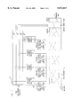
- FIG. 1 provides a functional view, at a particular point in time, of a joint decoder/DFE embodying the principles of the present invention
- FIG. 2 is a state transition diagram illustratively used in the decoder/DFE of FIG. 1 vis-a-vis coded signal points;
- FIG. 3 shows the joint decoder/DFE of FIG. 1 at a subsequent point in time
- FIG. 4 is a state transition diagram illustratively used in the decoder/DFE vis-a-vis uncoded signal points
- FIG. 5 is a combined block diagram/functional description view of the decoder/DFE of FIGS. 1 and 3 tailored for specific coded modulation;
- FIG. 6 is a state transition diagram illustratively used in the just mentioned specific coded modulation vis-a-vis coded signal points
- FIG. 7 is a state transition diagram used in the just mentioned specific coded modulation vis-a-vis uncoded signal points.
- FIG. 8 is similar to FIG. 5 but modified so as to implement my path-oriented, as opposed to state-oriented, approach to selecting surviving paths.
- the decoder/DFE of FIG. 1 is illustratively part of a receiving modem in which a signal x n , representing a transmitted signal point, is generated for the n th of a succession of signaling intervals.
- Signal x n was illustratively generated within the modem using conventional front-end steps such as sampling of an incoming line signal received from a telephone channel, demodulation and possibly feedforward equalization.
- Four replicas of x n are formed and a respective estimated intersymbol interference, or ISI, component is subtracted from each replica by a respective one of adders 10, to produce equalized signals x n .sup.(0) through x n .sup.(3).
- the ISI components are provided by respective ones of decision feedback equalizers 20, as described below.
- the transmitted signal points represented by the x n 's were generated in a transmit modem which used illustratively a probabilistic trellis coded modulation scheme of the type disclosed in my above-cited co-pending '351 and '829 patent applications.
- a transmit modem which used illustratively a probabilistic trellis coded modulation scheme of the type disclosed in my above-cited co-pending '351 and '829 patent applications.
- other codes may be preferred, such as the 64-state code shown in those patent applications.
- Viterbi decoder 30 of the decoder/DFE receives the equalized signals x n .sup.(0) through x n .sup.(3) and provides a so-called final decision P n-8 associated with the earlier signal x n-8 .
- the notation here indicates that the final decision that is output by Viterbi decoder 30 as to the value of a particular x n is delayed by, in this example, 8 signaling intervals, this corresponding to the so-called decoding depth of the Viterbi decoder.
- the decoding depth of 8 is used herein for purposes of illustration. In actual practice, the decoding depth depends on the code that is being used and will typically be greater than 8.
- the representation of Viterbi decoder 30 in FIG. 1 includes a representation of the so-called trellis--made up of concatentations of the trellis code's state transition diagram, as described below--and further shows the so-called surviving paths extending through the trellis, each surviving path being associated with, and terminating on, one of the four states of the code, those states being denominated 0, 1, 2 and 3.
- the coder in the transmit modem proceeds through a sequence of states which, in turn, defines a unique sequence of signal point subsets of a signal constellation.
- the coder output is a sequence of signal points each selected from a respective subset of the subset sequence thus defined.
- the task of the Viterbi decoder is to determine what the most likely sequence of signal points actually was, and central to that task is to determine the most likely sequence of transmitted signal points leading into each state of the code at any point in time. These are the aforementioned surviving paths, and the signal points along each path constitute a sequence of tentative signal point decisions.
- a metric is maintained for each surviving path, and, as described below, the current equalized signals x n .sup.(0) through x n .sup.(3) arc used to determine new surviving paths having updated path metrics.
- a final decision is thereupon made as to the value of one of the transmitted signal points-specifically one that was transmitted (in this case) 8 signaling intervals earlier.
- Each of DFEs 20 is associated with a particular one of the code states 0, 1,2 and 3.
- each DFE generates its respective ISI estimate as a function of the tentative signal point decisions which lie along the surviving path leading to the code state associated with that DFE.
- the ensemble of tentative signal point decisions along each newly determined surviving path are applied to the associated DFE in preparation for the generation of next set of ISI estimates to be applied to adders 10.
- a DFE forms its ISI estimate by forming a combination (illustratively a linear combination) of the decisions that have been input to it using an ensemble of coefficients whose values may be adaptively updated.
- each of the equalized signals x n .sup.(0) through x n .sup.(3) is associated with a particular state of the code in that the ISI estimate that was used to form that equalized signal was generated as a function of the then surviving path leading to the state in question.
- the process by which, as mentioned above, the current equalized signals x n .sup.(0) through x n .sup.(3) are used to determine new surviving paths having updated path metrics is carried out by updating unit 31 within Viterbi decoder 30.
- updating unit 31 Associated with the code in question is a so-called state transition diagram which defines, for each current code state, which next state or states the coder is allowed to transition to.
- the code can transition from current state 0 to either next state 0 or next state 1; from current state 1 to either next state 2 or next state 3; from current state 2 to either next state 0 or next state 1; and from current state 3 to either next state 2 or next state 3.
- 2 illustrative values of the eight branch metrics are 0.4, 0.6, 0.3, 0.5, 0.5, 0.2, 0.2 and 0.1.
- the particular one of the equalized signals x n .sup.(0) through x n .sup.(3) that is used to calculate any given one of the branch metrics is the equalized signal associated with the state from which that branch emanates.
- the present invention is directed to a joint decoder/DFE which is designed to provide accurate ISI estimates in such an environment, and in accordance with the invention, ISI estimates for the uncoded signal points are generated in response to tentative decisions as to the coded signal points as formed by the Viterbi decoder.
- the signal points along the very best surviving path within the Viterbi decoder can be used as the past decisions input to a DFE used to form the ISI estimate for one of the uncoded signal points and an immediate final decision as to the uncoded signal point can be made. That decision would also be applied to whatever DFEs are employed in the system (such as the per-state DFEs mentioned above) and used over a number of subsequent signaling intervals to represent the value of the uncoded signal point in question.
- FIG. 3 A more powerful, and preferred, implementation of the invention, however, is as shown in FIG. 3.
- Each uncoded signal point tentative decision is used to extend the surviving path for the associated state and, in preferred embodiments, to also update its path metric.
- FIG. 3 is similar to FIG. 1, except that since the received signal x n+1 represents an uncoded signal point, the state transition diagram used in updating unit 31 is that shown in FIG. 4.
- the state transition diagram used by updating unit 31 for uncoded signal points simply comprises four parallel branches, each extending from the current state to the same next state, i.e., current state 0 to next state 0 , current state 1 to next state 1 , and so forth.
- a decision is made as soon as each signal is received as to whether it represents a coded or uncoded signal point.
- C 1 for the illustrative (n+1) st signaling interval represented by FIG. 3.
- Each one of equalized signals x n+1 .sup.(0) through x n+1 .sup.(3) is used to calculate a respective one of the four branch metrics--given by the squared Euclidian distance between that equalized signal and the closest encoded signal point of the transmit constellation.
- the four branch metrics are illustratively 0.5, 0.2, 0.3 and 0.3.
- each new surviving path is simply an extended version of the surviving path previously extending into that state. Also as before, the very best surviving path is identified-now it is the path leading into state 1--and a final decision P n-7 is output, it being the signal point along that very best surviving path from 7 signaling intervals earlier.
- FIG. 5 provides a combined block diagram/functional description view of the decoder/DFE of FIGS. 1 and 3 tailored for probablistic trellis-coded modulation of the type described in the above-cited patent applications.
- the coded signal points are the signal points of the so-called inner sub-constellation of the overall signal constellation and the uncoded signal points are the signal points of the so-called outer sub-constellation of the overall signal constellation.
- the code used is that implemented by the coder shown in FIG. 5 of my above-cited '829 patent application. The state transition diagram for that code is shown in the present FIG.
- the received signal x n is processed at block 51 to produce an equalized signal associated with each state of the code.
- the functionality of this block is that for each state, i, of the code, an equalized signal x n .sup.(i) is formed using a DFE whose inputs are the tentative past decisions along the surviving path associated with the i th state.
- a signal indicative of whether the received signal represents a coded, inner sub-constellation, signal point or an uncoded, outer sub-constellation signal point is provided by sub-constellation decision block 52 in a manner to be described. That signal corresponds to one-bit control signal C in FIGS. 1 and 3.
- switch 53 is in the "down" position and the equalized signals are processed at block 56.
- the functionality of this block is that for each state, i, of the code, we use x n .sup.(i) to find a) the closest signal point in the subset associated with each branch and b) the branch metric for each branch emanating from that state based on the state transition diagram of FIG. 6.
- the path metrics and the surviving paths are updated based on the same state transitiondiagram.
- Switch 58 will be in the "down" position at this time so that the flow proceeds to block 59 at which the very best surviving path is found and a final output decision is made.
- switch 53 is in the "up" position and the equalized signals are processed at block 54.
- the functionality of this block is essentially similar to that of block 56 except that the state transition diagram is that shown in FIG. 7.
- the state transition diagram of FIG. 7 comprises a single branch emanating from each current state and extending to the same next state. Each branch is associated with the entire outer sub-constellation.
- the functionality of this block is that for each state, i, of the code, we use x n .sup.(i) to find a) the closest outer sub-constellation signal point and b) the branch metric for the branch emanating from that state. Then, at block 55, the path metric is updated and the surviving path is extended, as noted earler. Switch 58 will be in the "up" position at this time so that the flow proceeds to block 59 at which, as before, the very best surviving path is found and a final output decision is made.
- a decision as to whether signal x n represents an inner or outer sub-constellation signal point would be most accurately made if one were to wait for the Viterbi decoder to provide a final decision as to that signal. However, that decision must be made at sub-constellation decision block 52 soon as the signal is received.
- a combining step 62 and a decision feedback equalization block 61 are used to form an equalized signal x n .sup.(b) at the time signal x n is received, the inputs of block 61 being the tentative past decisions from the very best surviving path of the Viterbi decoder.
- subconstellation decision block 52 makes the inner or outer subconstellation decision.
- the constellation may be designed in such a way that the distance between its inner and outer sub-constellations is greater than would be otherwise dictated by other design criteria, e.g., greater than the effective minimum distance of the overall modulation scheme.
- Such a constellation is shown in Appendix I hereof, this constellation being very similar to that shown in Appendix II of the '829 application except that the distance between the inner and outer sub-constellations has been increased from 16 to 32.
- the constellation shown in Appendix III of the '829 application may be used for the bit-robbed signaling intervals.
- a bit robbing indicator indicating the occurrence of a bit-robbed signaling interval would be applied at blocks 52, 54 and 56, causing the use of that constellation at those blocks.
- the constellation shown in Appendix II hereof may be used instead, it having a distance between the inner and outer sub-constellations of 44, as compared to 16 for the constellation shown in Appendix III of the '829 application.
- a further consideration relative to bit robbing is as follows: On the one hand, although a transmitted signal point can be received as another signal point due to bit robbing, both of those signal points map back into the same transmitted bit pattern so from that standpoint there is no problem, as discussed in my '829 application. A potential problem arises, however, in that the decision as to the amplitude of the signal point is fed back to the DFE and it is possible that, due to noise and impairments between the receiving central office and the receiving modem, the signal point that was transmitted from the central office to the receiving modem may become so displaced that an incorrect decision is made in the receiving modem as to which of the two signal points was sent. The presence of this incorrect decision in the DFE will have a negative effect on the accuracy of the decoding process.
- the constellation of Appendix III is comprised solely of an outer sub-constellation whose smallest magnitude signal points are ⁇ 247.5. No signal points of smaller amplitude can be used because below the magnitude of 247.5, the distance between each pair of signal points is less than 15, thereby violating the desired design constraint. Moreover, since the minimum distance of 16 between different pairs of signal points of the constellation of Appendix III is already greater than the effective minimum distance of the overall modulation scheme, there would be no benefit to using coding to that constellation. It may be noted that the number of signal point pairs in this constellation is 30. As a consequence, this approach will support one less bit during the bit-robbed intervals than for the case of Appendix II. The choice between the use of the constellations of Appendices II and III will be made based on whether one is willing to endure the lower level of error rate performance provided by the constellation of Appendix II in order to have a higher bandwidth efficiency.
- the other approach is to design the constellation in such a way that the distance between each pair of points that become one another due to bit robbing is much smaller than the effective minimum distance of the overall modulation scheme, so that an error made in the receiver as to which one was transmitted will have a negligible effect on the decoder/DFE performance.
- both of these approaches together, for example, having an inner, coded sub-constellation wherein each pair of signal points are very close together and an uncoded outer sub-constellation wherein each pair of signal points are very far apart, as just described.
- path-oriented approach the paths that are retained as the surviving paths are some number, M, of the paths which have the smallest path metrics, even if two or more of those paths may come into a given state. I have discovered that this path-oriented approach will achieve substantially the same (or only negligibly worse) level of performance as the state-oriented approach with a much reduced level of decoder complexity.
- M 16--that is, retaining only the 16 best paths--and achieve essentially the same performance as the much more complex state-oriented approach in which 64 paths--one for each state--are retained.
- FIG. 8 shows the implementation of my path-oriented approach for joint decoder/DFE in the present context of probablistic TCM. More particularly, various elements shown in FIG. 8 correspond, either exactly, or with modifications, to those shown in FIG. 5. Those that correspond exactly bear the same reference numeral, whereas blocks 51, 54, 55, 56 and 57 are replaced in FIG. 8 with blocks 851, 854, 855, 856 and 857.
- blocks 851, 854 and 856 the calculations that are carried out vis-a-vis the equalized signal x n .sup.(i) are carried out for each M best surviving paths rather than for each state of the code. And in blocks 855 and 857 a new set of M best surviving paths are identified, along with their associated path metrics, rather than, as in FIG. 5, identifying an updated surviving path, and its associated metric, for each state.
- any element expressed as a means for performing a specified function is intended to encompass any way of performing that function including, for example, a) a combination of circuit elements which performs that function or b) software in any form (including, therefore, firmware, microcode or the like) combined with appropriate circuitry for executing that software to perform the function.
- the invention is defined by such claims resides in the fact that the functionalities provided by the various recited means are combined and brought together in the manner which the claims call for. Applicant thus regards any means which can provide those functionalities as equivalent as those shown herein.
Abstract
Description
Claims (9)
Priority Applications (4)
| Application Number | Priority Date | Filing Date | Title |
|---|---|---|---|
| US08/936,649 US5872817A (en) | 1997-07-02 | 1997-09-24 | Joint viterbi decoder and decision feedback equalizer |
| EP98304933A EP0889612B1 (en) | 1997-07-02 | 1998-06-23 | Maximum-likelihood decoding method for coded modulation |
| JP18706998A JP3280622B2 (en) | 1997-07-02 | 1998-07-02 | Joint Viterbi decoder and decision feedback equalizer |
| KR1019980027735A KR100583897B1 (en) | 1997-07-02 | 1998-07-02 | Combined Viterbit Decoder and Crystal Feedback Equalizer |
Applications Claiming Priority (2)
| Application Number | Priority Date | Filing Date | Title |
|---|---|---|---|
| US5156197P | 1997-07-02 | 1997-07-02 | |
| US08/936,649 US5872817A (en) | 1997-07-02 | 1997-09-24 | Joint viterbi decoder and decision feedback equalizer |
Publications (1)
| Publication Number | Publication Date |
|---|---|
| US5872817A true US5872817A (en) | 1999-02-16 |
Family
ID=26729558
Family Applications (1)
| Application Number | Title | Priority Date | Filing Date |
|---|---|---|---|
| US08/936,649 Expired - Lifetime US5872817A (en) | 1997-07-02 | 1997-09-24 | Joint viterbi decoder and decision feedback equalizer |
Country Status (4)
| Country | Link |
|---|---|
| US (1) | US5872817A (en) |
| EP (1) | EP0889612B1 (en) |
| JP (1) | JP3280622B2 (en) |
| KR (1) | KR100583897B1 (en) |
Cited By (50)
| Publication number | Priority date | Publication date | Assignee | Title |
|---|---|---|---|---|
| US6151370A (en) * | 1998-02-12 | 2000-11-21 | Lucent Technologies Inc. | Path-oriented decoder for signal-dependent noise |
| US6195386B1 (en) * | 1994-09-26 | 2001-02-27 | Texas Instruments Incorporated | Parallel decision feedback equalizer |
| US6252904B1 (en) * | 1998-11-13 | 2001-06-26 | Broadcom Corporation | High-speed decoder for a multi-pair gigabit transceiver |
| EP1119145A1 (en) * | 2000-01-20 | 2001-07-25 | TELEFONAKTIEBOLAGET LM ERICSSON (publ) | Parallel decision feedback equalizer with adaptive thresholding based on noise estimates |
| US20010019584A1 (en) * | 1998-11-13 | 2001-09-06 | Broadcom Corporation | System and method for high-speed decoding and ISI compensation in a multi-pair transceiver system |
| US6324226B1 (en) | 1999-11-22 | 2001-11-27 | Matsushita Electric Industrial Co., Ltd. | Viterbi decoder |
| US6356586B1 (en) * | 1999-09-03 | 2002-03-12 | Lucent Technologies, Inc. | Methods and apparatus for parallel decision-feedback decoding in a communication system |
| US20020097795A1 (en) * | 2000-11-13 | 2002-07-25 | Jingsong Xia | Equalizer for time domain signal processing |
| US20020171759A1 (en) * | 2001-02-08 | 2002-11-21 | Handjojo Benitius M. | Adaptive interlace-to-progressive scan conversion algorithm |
| US20020191689A1 (en) * | 2001-06-19 | 2002-12-19 | Jingsong Xia | Combined trellis decoder and decision feedback equalizer |
| US20020191716A1 (en) * | 2001-06-07 | 2002-12-19 | Jingsong Xia | Error generation for adaptive equalizer |
| US6505222B1 (en) | 1999-10-29 | 2003-01-07 | International Business Machines Corporation | Systems methods and computer program products for controlling undesirable bias in an equalizer |
| US6553518B1 (en) | 1999-03-08 | 2003-04-22 | International Business Machines Corporation | Severe error detectors, methods and computer program products that use constellation specific error event thresholds to detect severe error events during demodulation of a signal comprising symbols from a plurality of symbol constellations |
| US6570919B1 (en) * | 1999-07-30 | 2003-05-27 | Agere Systems Inc. | Iterative decoding of data packets employing decision feedback equalization |
| US20030138040A1 (en) * | 2002-01-22 | 2003-07-24 | Rouphael Antoine J. | Multilevel decision feedback equalizer |
| US6600617B1 (en) | 2000-03-07 | 2003-07-29 | International Business Machines Corporation | Method and apparatus for adjusting digital filter taps based upon minimization of viterbi margin counts |
| US6611563B1 (en) | 1999-10-29 | 2003-08-26 | International Business Machines Corporation | Systems, methods and computer program products for data mode refinement of modem constellation points |
| WO2003088481A1 (en) * | 2002-04-05 | 2003-10-23 | Micronas Semiconductors, Inc. | Synchronization symbol re-insertion for a decision feedback equalizer combined with a trellis decoder |
| US20030206053A1 (en) * | 2002-04-04 | 2003-11-06 | Jingsong Xia | Carrier recovery for DTV receivers |
| US6650657B1 (en) | 1999-10-29 | 2003-11-18 | International Business Machines Corporation | Systems, methods and computer program products for identifying digital impairments in modem signals |
| US20030214350A1 (en) * | 2002-04-05 | 2003-11-20 | Citta Richard W. | Data-directed frequency acquisition loop |
| US20030215044A1 (en) * | 2002-04-05 | 2003-11-20 | Citta Richard W. | Data-directed frequency-and-phase lock loop |
| US6662322B1 (en) | 1999-10-29 | 2003-12-09 | International Business Machines Corporation | Systems, methods, and computer program products for controlling the error rate in a communication device by adjusting the distance between signal constellation points |
| US6661847B1 (en) | 1999-05-20 | 2003-12-09 | International Business Machines Corporation | Systems methods and computer program products for generating and optimizing signal constellations |
| US20030235259A1 (en) * | 2002-04-04 | 2003-12-25 | Jingsong Xia | System and method for symbol clock recovery |
| US20040013191A1 (en) * | 2002-04-05 | 2004-01-22 | Shidong Chen | Transposed structure for a decision feedback equalizer combined with a trellis decoder |
| US6690739B1 (en) | 2000-01-14 | 2004-02-10 | Shou Yee Mui | Method for intersymbol interference compensation |
| US20040071243A1 (en) * | 1998-11-09 | 2004-04-15 | Agazzi Oscar E. | Multi-pair gigabit ethernet transceiver |
| US20040091039A1 (en) * | 2001-06-06 | 2004-05-13 | Jingsong Xia | Adaptive equalizer having a variable step size influenced by output from a trellis decoder |
| US6754258B1 (en) | 1999-10-29 | 2004-06-22 | International Business Machines Corporation | Systems, methods and computer program products for averaging learned levels in the presence of digital impairments based on patterns |
| US20040128610A1 (en) * | 2002-12-26 | 2004-07-01 | Lee-Fang Wei | Method and apparatus for using multi-dimensional trellis codes over multi-path channels |
| US6760385B1 (en) * | 2000-05-30 | 2004-07-06 | Adtran, Inc. | Universal parallel processing decoder |
| US6765955B1 (en) | 1999-10-29 | 2004-07-20 | International Business Machines Corporation | Methods, systems and computer program products establishing a communication configuration for a modem connection to compensate for echo noise |
| US20040146100A1 (en) * | 2002-09-19 | 2004-07-29 | Samsung Electronics Co., Ltd. | Channel equalizer of single carrier receiver and equalizing method thereof |
| US6792004B1 (en) | 1999-10-29 | 2004-09-14 | International Business Machines Corporation | Systems, methods and computer program products for averaging learned levels in the presence of robbed-bit signaling based on proximity |
| US6792040B1 (en) | 1999-10-29 | 2004-09-14 | International Business Machines Corporation | Modems having a dual power mode capability and methods of operating same |
| US6816545B1 (en) | 1999-10-29 | 2004-11-09 | International Business Machines Corporation | Systems, methods and computer program products for identifying digital impairments in modems based on clusters and/or skips in pulse code modulation signal levels |
| US6823004B1 (en) | 1999-10-29 | 2004-11-23 | International Business Machines Corporation | Methods, systems and computer program products for monitoring performance of a modem during a connection |
| US6823017B1 (en) | 1999-10-29 | 2004-11-23 | International Business Machines Corporation | Systems, methods and computer program products for filtering glitches from measured values in a sequence of code points |
| US6826157B1 (en) | 1999-10-29 | 2004-11-30 | International Business Machines Corporation | Systems, methods, and computer program products for controlling data rate reductions in a communication device by using a plurality of filters to detect short-term bursts of errors and long-term sustainable errors |
| US20050074082A1 (en) * | 2002-04-05 | 2005-04-07 | Citta Richard W. | Data-directed frequency-and-phase lock loop for decoding an offset-QAM modulated signal having a pilot |
| US20050213670A1 (en) * | 2000-04-06 | 2005-09-29 | Lee-Fang Wei | Upstream data transmission |
| US20070183489A1 (en) * | 2006-02-07 | 2007-08-09 | Samsung Electronics Co., Ltd. | Apparatus for decoding a signal and method thereof and a trellis coded modulation decoder and method thereof |
| US20070189376A1 (en) * | 2000-03-10 | 2007-08-16 | Arthur Abnous | Architecture for very high-speed decision feedback sequence estimation |
| CN100364257C (en) * | 2005-05-26 | 2008-01-23 | 上海奇普科技有限公司 | Time-domain adaptive aqualizer combined with NR code |
| CN100413295C (en) * | 2002-11-01 | 2008-08-20 | 上海奇普科技有限公司 | Self Adaptive equalizer for improving error signal production |
| US20090052516A1 (en) * | 2007-08-23 | 2009-02-26 | Freescale Semiconductor, Inc. | Per-survivor based adaptive equalizer |
| US20090252202A1 (en) * | 2004-12-10 | 2009-10-08 | Koninklijke Philips Electronics, N.V. | Method and apparatus for enhanced decoding in multi-band ultra-wideband communications |
| US20130028299A1 (en) * | 2011-07-26 | 2013-01-31 | Himax Media Solutions, Inc. | Adaptive ethernet transceiver with joint decision feedback equalizer and trellis decoder |
| US8938035B1 (en) | 2012-02-29 | 2015-01-20 | Marvell International Ltd. | System and method for transferring data over a two-pair communication system |
Families Citing this family (18)
| Publication number | Priority date | Publication date | Assignee | Title |
|---|---|---|---|---|
| EP0946024A1 (en) * | 1998-03-25 | 1999-09-29 | Ascom Systec AG | Decision feedback equalisation, in particular for data communication over powrr distribution networks |
| DE69922405T2 (en) * | 1998-11-09 | 2006-01-12 | Broadcom Corp., Irvine | METHOD AND SYSTEM FOR DECISION RECONDITIONED DECODING |
| US6226332B1 (en) | 1998-11-13 | 2001-05-01 | Broadcom Corporation | Multi-pair transceiver decoder system with low computation slicer |
| US6253345B1 (en) | 1998-11-13 | 2001-06-26 | Broadcom Corporation | System and method for trellis decoding in a multi-pair transceiver system |
| US6421395B1 (en) * | 1999-02-09 | 2002-07-16 | Lucent Technologies Inc. | Termination of coded or uncoded modulation with path-oriented decoder |
| US6327317B1 (en) * | 1999-09-10 | 2001-12-04 | Telefonaktiebolaget Lm Ericsson (Publ) | Combined equalization and decoding techniques |
| FR2798540B1 (en) * | 1999-09-13 | 2001-11-23 | France Telecom | METHOD OF JOINT DECODING AND EQUALIZATION OF A DIGITAL SIGNAL PROTECTED BY A CODE DEFINED BY A MESH |
| US6754294B1 (en) | 1999-11-12 | 2004-06-22 | Cornell Research Foundation, Inc. | Dual equalizer for use in an receiver and method of operation |
| US7106813B1 (en) * | 2000-03-16 | 2006-09-12 | Qualcomm, Incorporated | Method and apparatus for combined soft-decision based interference cancellation and decoding |
| US7006566B2 (en) * | 2001-04-10 | 2006-02-28 | Koninklijke Philips Electronics N.V. | Two stage equalizer for trellis coded systems |
| US6734920B2 (en) * | 2001-04-23 | 2004-05-11 | Koninklijke Philips Electronics N.V. | System and method for reducing error propagation in a decision feedback equalizer of ATSC VSB receiver |
| US6823489B2 (en) * | 2001-04-23 | 2004-11-23 | Koninklijke Philips Electronics N.V. | Generation of decision feedback equalizer data using trellis decoder traceback output in an ATSC HDTV receiver |
| US6760373B2 (en) | 2001-08-02 | 2004-07-06 | Aware, Inc. | Systems and methods for multicarrier modulation using multi-tap frequency-domain equalizer and decision feedback |
| US20040096008A1 (en) * | 2002-08-01 | 2004-05-20 | Aware, Inc. | Multi-tap frequency domain equalization with decision feedback and trellis decoding |
| DE60318126T2 (en) * | 2002-08-01 | 2008-12-04 | Research In Motion Ltd., Waterloo | Mobile station for maintaining always-on wireless internet protocol communication and method therefor |
| KR100539248B1 (en) | 2004-02-05 | 2005-12-27 | 삼성전자주식회사 | Decision-feedback equalizer and Method of feedback filter coefficient updating |
| JP5432288B2 (en) * | 2008-12-31 | 2014-03-05 | エスティー‐エリクソン、ソシエテ、アノニム | Process and receiver for interference cancellation of interfering base stations in a synchronous OFDM system |
| CN102882817B (en) * | 2012-09-26 | 2017-07-14 | 华为技术有限公司 | Equalizing circuit, data transmission system and equalization methods |
Citations (3)
| Publication number | Priority date | Publication date | Assignee | Title |
|---|---|---|---|---|
| US5056117A (en) * | 1989-08-07 | 1991-10-08 | At&T Bell Laboratories | Decision feedback equalization with trellis coding |
| US5775855A (en) * | 1995-06-08 | 1998-07-07 | Valenite Inc. | Cutting insert and cutter for milling |
| US5787127A (en) * | 1995-08-23 | 1998-07-28 | Oki Electric Industry Co., Ltd. | Viterbi decoding method and apparatus with balance among memory and processing requirements |
Family Cites Families (3)
| Publication number | Priority date | Publication date | Assignee | Title |
|---|---|---|---|---|
| US617678A (en) | 1899-01-10 | emery | ||
| US5953376A (en) | 1996-09-26 | 1999-09-14 | Lucent Technologies Inc. | Probabilistic trellis coded modulation with PCM-derived constellations |
| US6157678A (en) | 1996-12-18 | 2000-12-05 | Lucent Technologies Inc. | Probabilistic trellis/coded modulation with PCM-derived constellations |
-
1997
- 1997-09-24 US US08/936,649 patent/US5872817A/en not_active Expired - Lifetime
-
1998
- 1998-06-23 EP EP98304933A patent/EP0889612B1/en not_active Expired - Lifetime
- 1998-07-02 JP JP18706998A patent/JP3280622B2/en not_active Expired - Fee Related
- 1998-07-02 KR KR1019980027735A patent/KR100583897B1/en not_active IP Right Cessation
Patent Citations (3)
| Publication number | Priority date | Publication date | Assignee | Title |
|---|---|---|---|---|
| US5056117A (en) * | 1989-08-07 | 1991-10-08 | At&T Bell Laboratories | Decision feedback equalization with trellis coding |
| US5775855A (en) * | 1995-06-08 | 1998-07-07 | Valenite Inc. | Cutting insert and cutter for milling |
| US5787127A (en) * | 1995-08-23 | 1998-07-28 | Oki Electric Industry Co., Ltd. | Viterbi decoding method and apparatus with balance among memory and processing requirements |
Non-Patent Citations (8)
| Title |
|---|
| A. Duel Hallen et al., Delayed Decision Feedback Sequence Estimation, IEEE Transactions on Communications , vol. 37, No. 5, 428 436 (May 1989). * |
| A. Duel-Hallen et al., "Delayed Decision-Feedback Sequence Estimation, " IEEE Transactions on Communications, vol. 37, No. 5, 428-436 (May 1989). |
| M.V. Eyuboglu et al., "Reduced-State Sequence Estimation for Coded Modulation on Intersymbol Interference Channels," IEEE Journal on Selected Areas in Communications, vol. 7, No. 6, 989-995 (Aug. 1989). |
| M.V. Eyuboglu et al., Reduced State Sequence Estimation for Coded Modulation on Intersymbol Interference Channels, IEEE Journal on Selected Areas in Communications , vol. 7, No. 6, 989 995 (Aug. 1989). * |
| P.R. Chevillat et al., "Decoding of Trellis-Encoded Signals in the Presence of Intersymbol Interference and Noise," IEEE Transactions on Communications, vol. 37, No. 7, 669-676 (Jul. 1989). |
| P.R. Chevillat et al., Decoding of Trellis Encoded Signals in the Presence of Intersymbol Interference and Noise, IEEE Transactions on Communications , vol. 37, No. 7, 669 676 (Jul. 1989). * |
| U.S. application No. 08/753,351 filed Nov. 25, 1996. * |
| U.S. application No. 08/855829 filed May 12, 1997. * |
Cited By (107)
| Publication number | Priority date | Publication date | Assignee | Title |
|---|---|---|---|---|
| US6195386B1 (en) * | 1994-09-26 | 2001-02-27 | Texas Instruments Incorporated | Parallel decision feedback equalizer |
| US6151370A (en) * | 1998-02-12 | 2000-11-21 | Lucent Technologies Inc. | Path-oriented decoder for signal-dependent noise |
| US20070183540A1 (en) * | 1998-11-09 | 2007-08-09 | Agazzi Oscar E | Multi-pair gigabit ethernet transceiver having adaptive disabling of circuit elements |
| US20110096824A1 (en) * | 1998-11-09 | 2011-04-28 | Agazzi Oscar E | Multi-pair gigabit ethernet transceiver having a single-state decision feedback equalizer |
| US20100309963A1 (en) * | 1998-11-09 | 2010-12-09 | Agazzi Oscar E | Multi-pair gigabit ethernet transceiver having adaptive disabling of circuit elements |
| US20040071243A1 (en) * | 1998-11-09 | 2004-04-15 | Agazzi Oscar E. | Multi-pair gigabit ethernet transceiver |
| US7305029B2 (en) * | 1998-11-09 | 2007-12-04 | Broadcom Corporation | Multi-pair gigabit ethernet transceiver |
| US20070242739A1 (en) * | 1998-11-09 | 2007-10-18 | Agazzi Oscar E | Multi-pair gigabit ethernet transceiver having a single-state decision feedback equalizer |
| US8451885B2 (en) | 1998-11-09 | 2013-05-28 | Broadcom Corporation | Multi-pair gigabit ethernet transceiver having adaptive disabling of circuit elements |
| US7792186B2 (en) * | 1998-11-09 | 2010-09-07 | Broadcom Corporation | Multi-pair gigabit ethernet transceiver having a single-state decision feedback equalizer |
| US7453935B2 (en) | 1998-11-09 | 2008-11-18 | Broadcom Corporation | Multi-pair gigabit ethernet transceiver having decision feedback equalizer |
| US7570701B2 (en) | 1998-11-09 | 2009-08-04 | Broadcom Corporation | Multi-pair gigabit ethernet transceiver |
| US7733952B2 (en) | 1998-11-09 | 2010-06-08 | Broadcom Corporation | Multi-pair gigabit Ethernet transceiver having adaptive disabling of circuit elements |
| US20080151988A1 (en) * | 1998-11-09 | 2008-06-26 | Agazzi Oscar E | Multi-pair gigabit ethernet transceiver |
| US20070195875A1 (en) * | 1998-11-09 | 2007-08-23 | Agazzi Oscar E | Multi-pair gigabit ethernet transceiver having decision feedback equalizer |
| US7801241B2 (en) | 1998-11-09 | 2010-09-21 | Broadcom Corporation | Multi-pair gigabit Ethernet transceiver |
| US7801240B2 (en) | 1998-11-09 | 2010-09-21 | Broadcom Corporation | Multi-pair gigabit ethernet transceiver |
| US20090296791A1 (en) * | 1998-11-09 | 2009-12-03 | Agazzi Oscar E | Multi-Pair Gigabit Ethernet Transceiver |
| US7194029B2 (en) * | 1998-11-09 | 2007-03-20 | Broadcom Corporation | Multi-pair gigabit ethernet transceiver having adaptive disabling or circuit elements |
| US20080049826A1 (en) * | 1998-11-09 | 2008-02-28 | Agazzi Oscar E | Graphics Accelerator |
| US8306104B2 (en) | 1998-11-09 | 2012-11-06 | Broadcom Corporation | Method and device for multi-dimensional processing using a single-state decision feedback equalizer |
| US7769101B2 (en) * | 1998-11-09 | 2010-08-03 | Broadcom Corporation | Multi-pair gigabit ethernet transceiver |
| US7194028B2 (en) * | 1998-11-09 | 2007-03-20 | Broadcom Corporation | Multi-Pair Gigabit Ethernet Transceiver having decision feedback equalizer |
| US8031799B2 (en) * | 1998-11-09 | 2011-10-04 | Broadcom Corporation | Multi-pair gigabit ethernet transceiver |
| US20090180529A1 (en) * | 1998-11-09 | 2009-07-16 | Agazzi Oscar E | Multi-pair gigabit ethernet transceiver |
| US20020006173A1 (en) * | 1998-11-13 | 2002-01-17 | Broadcom Corporation | High-speed decoder for a multi-pair gigabit transceiver |
| US20060245487A1 (en) * | 1998-11-13 | 2006-11-02 | Agazzi Oscar E | High-speed decoder for a multi-pair gigabit transceiver |
| US8259787B2 (en) * | 1998-11-13 | 2012-09-04 | Broadcom Corporation | High-speed decoder for a multi-pair gigabit transceiver |
| US6959038B2 (en) * | 1998-11-13 | 2005-10-25 | Broadcom Corporation | High-speed decoder for a multi-pair gigabit transceiver |
| US6252904B1 (en) * | 1998-11-13 | 2001-06-26 | Broadcom Corporation | High-speed decoder for a multi-pair gigabit transceiver |
| US7630434B2 (en) * | 1998-11-13 | 2009-12-08 | Broadcom Corporation | High-speed decoder for a multi-pair gigabit transceiver |
| US20010019584A1 (en) * | 1998-11-13 | 2001-09-06 | Broadcom Corporation | System and method for high-speed decoding and ISI compensation in a multi-pair transceiver system |
| US20100086019A1 (en) * | 1998-11-13 | 2010-04-08 | Agazzi Oscar E | High-Speed Decoder for a Multi-Pair Gigabit Transceiver |
| US6947482B2 (en) * | 1998-11-13 | 2005-09-20 | Broadcom Corporation | System and method for high-speed decoding and ISI compensation in a multi-pair transceiver system |
| US6553518B1 (en) | 1999-03-08 | 2003-04-22 | International Business Machines Corporation | Severe error detectors, methods and computer program products that use constellation specific error event thresholds to detect severe error events during demodulation of a signal comprising symbols from a plurality of symbol constellations |
| US6661847B1 (en) | 1999-05-20 | 2003-12-09 | International Business Machines Corporation | Systems methods and computer program products for generating and optimizing signal constellations |
| US6570919B1 (en) * | 1999-07-30 | 2003-05-27 | Agere Systems Inc. | Iterative decoding of data packets employing decision feedback equalization |
| US6356586B1 (en) * | 1999-09-03 | 2002-03-12 | Lucent Technologies, Inc. | Methods and apparatus for parallel decision-feedback decoding in a communication system |
| US6611563B1 (en) | 1999-10-29 | 2003-08-26 | International Business Machines Corporation | Systems, methods and computer program products for data mode refinement of modem constellation points |
| US6505222B1 (en) | 1999-10-29 | 2003-01-07 | International Business Machines Corporation | Systems methods and computer program products for controlling undesirable bias in an equalizer |
| US6816545B1 (en) | 1999-10-29 | 2004-11-09 | International Business Machines Corporation | Systems, methods and computer program products for identifying digital impairments in modems based on clusters and/or skips in pulse code modulation signal levels |
| US6823004B1 (en) | 1999-10-29 | 2004-11-23 | International Business Machines Corporation | Methods, systems and computer program products for monitoring performance of a modem during a connection |
| US6823017B1 (en) | 1999-10-29 | 2004-11-23 | International Business Machines Corporation | Systems, methods and computer program products for filtering glitches from measured values in a sequence of code points |
| US6826157B1 (en) | 1999-10-29 | 2004-11-30 | International Business Machines Corporation | Systems, methods, and computer program products for controlling data rate reductions in a communication device by using a plurality of filters to detect short-term bursts of errors and long-term sustainable errors |
| US6662322B1 (en) | 1999-10-29 | 2003-12-09 | International Business Machines Corporation | Systems, methods, and computer program products for controlling the error rate in a communication device by adjusting the distance between signal constellation points |
| US6792004B1 (en) | 1999-10-29 | 2004-09-14 | International Business Machines Corporation | Systems, methods and computer program products for averaging learned levels in the presence of robbed-bit signaling based on proximity |
| US6650657B1 (en) | 1999-10-29 | 2003-11-18 | International Business Machines Corporation | Systems, methods and computer program products for identifying digital impairments in modem signals |
| US6754258B1 (en) | 1999-10-29 | 2004-06-22 | International Business Machines Corporation | Systems, methods and computer program products for averaging learned levels in the presence of digital impairments based on patterns |
| US6765955B1 (en) | 1999-10-29 | 2004-07-20 | International Business Machines Corporation | Methods, systems and computer program products establishing a communication configuration for a modem connection to compensate for echo noise |
| US6792040B1 (en) | 1999-10-29 | 2004-09-14 | International Business Machines Corporation | Modems having a dual power mode capability and methods of operating same |
| US6324226B1 (en) | 1999-11-22 | 2001-11-27 | Matsushita Electric Industrial Co., Ltd. | Viterbi decoder |
| US6690739B1 (en) | 2000-01-14 | 2004-02-10 | Shou Yee Mui | Method for intersymbol interference compensation |
| WO2001054366A3 (en) * | 2000-01-20 | 2001-09-13 | Ericsson Telefon Ab L M | Parallel decision feedback equalizer with adaptive thresholding based on noise estimates |
| WO2001054366A2 (en) * | 2000-01-20 | 2001-07-26 | Telefonaktiebolaget Lm Ericsson (Publ) | Parallel decision feedback equalizer with adaptive thresholding based on noise estimates |
| US6898239B2 (en) | 2000-01-20 | 2005-05-24 | Telefonaktiebolaget Lm Ericsson (Publ) | Method of detecting a sequence of information symbols, and a mobile station adapted to performing the method |
| EP1119145A1 (en) * | 2000-01-20 | 2001-07-25 | TELEFONAKTIEBOLAGET LM ERICSSON (publ) | Parallel decision feedback equalizer with adaptive thresholding based on noise estimates |
| US6600617B1 (en) | 2000-03-07 | 2003-07-29 | International Business Machines Corporation | Method and apparatus for adjusting digital filter taps based upon minimization of viterbi margin counts |
| US20100303144A1 (en) * | 2000-03-10 | 2010-12-02 | Arthur Abnous | Architecture for very high-speed decision feedback sequence estimation |
| US8934527B2 (en) * | 2000-03-10 | 2015-01-13 | Broadcom Corporation | Architecture for very high-speed decision feedback sequence estimation |
| US20070189376A1 (en) * | 2000-03-10 | 2007-08-16 | Arthur Abnous | Architecture for very high-speed decision feedback sequence estimation |
| US7738549B2 (en) * | 2000-03-10 | 2010-06-15 | Broadcom Corporation | Architecture for very high-speed decision feedback sequence estimation |
| US7272174B2 (en) * | 2000-04-06 | 2007-09-18 | Lucent Technologies Inc. | Upstream data transmission |
| US20050213671A1 (en) * | 2000-04-06 | 2005-09-29 | Lee-Fang Wei | Upstream data transmission |
| US7245675B2 (en) | 2000-04-06 | 2007-07-17 | Lucent Technologies Inc. | Upstream data transmission |
| US20050213670A1 (en) * | 2000-04-06 | 2005-09-29 | Lee-Fang Wei | Upstream data transmission |
| US6760385B1 (en) * | 2000-05-30 | 2004-07-06 | Adtran, Inc. | Universal parallel processing decoder |
| US20020097795A1 (en) * | 2000-11-13 | 2002-07-25 | Jingsong Xia | Equalizer for time domain signal processing |
| US7072392B2 (en) | 2000-11-13 | 2006-07-04 | Micronas Semiconductors, Inc. | Equalizer for time domain signal processing |
| US20020171759A1 (en) * | 2001-02-08 | 2002-11-21 | Handjojo Benitius M. | Adaptive interlace-to-progressive scan conversion algorithm |
| US6940557B2 (en) | 2001-02-08 | 2005-09-06 | Micronas Semiconductors, Inc. | Adaptive interlace-to-progressive scan conversion algorithm |
| US7130344B2 (en) | 2001-06-06 | 2006-10-31 | Micronas Semiconductors, Inc. | Adaptive equalizer having a variable step size influenced by output from a trellis decoder |
| US20040091039A1 (en) * | 2001-06-06 | 2004-05-13 | Jingsong Xia | Adaptive equalizer having a variable step size influenced by output from a trellis decoder |
| US6829297B2 (en) * | 2001-06-06 | 2004-12-07 | Micronas Semiconductors, Inc. | Adaptive equalizer having a variable step size influenced by output from a trellis decoder |
| US7190744B2 (en) | 2001-06-07 | 2007-03-13 | Micronas Semiconductors, Inc. | Error generation for adaptive equalizer |
| US20020191716A1 (en) * | 2001-06-07 | 2002-12-19 | Jingsong Xia | Error generation for adaptive equalizer |
| US7418034B2 (en) * | 2001-06-19 | 2008-08-26 | Micronas Semiconductors. Inc. | Combined trellis decoder and decision feedback equalizer |
| US20020191689A1 (en) * | 2001-06-19 | 2002-12-19 | Jingsong Xia | Combined trellis decoder and decision feedback equalizer |
| US7092438B2 (en) | 2002-01-22 | 2006-08-15 | Siemens Communications, Inc. | Multilevel decision feedback equalizer |
| US20030138040A1 (en) * | 2002-01-22 | 2003-07-24 | Rouphael Antoine J. | Multilevel decision feedback equalizer |
| US20030206053A1 (en) * | 2002-04-04 | 2003-11-06 | Jingsong Xia | Carrier recovery for DTV receivers |
| US20030235259A1 (en) * | 2002-04-04 | 2003-12-25 | Jingsong Xia | System and method for symbol clock recovery |
| US20030215044A1 (en) * | 2002-04-05 | 2003-11-20 | Citta Richard W. | Data-directed frequency-and-phase lock loop |
| US20030214350A1 (en) * | 2002-04-05 | 2003-11-20 | Citta Richard W. | Data-directed frequency acquisition loop |
| WO2003088481A1 (en) * | 2002-04-05 | 2003-10-23 | Micronas Semiconductors, Inc. | Synchronization symbol re-insertion for a decision feedback equalizer combined with a trellis decoder |
| US7321642B2 (en) | 2002-04-05 | 2008-01-22 | Micronas Semiconductors, Inc. | Synchronization symbol re-insertion for a decision feedback equalizer combined with a trellis decoder |
| CN100539410C (en) * | 2002-04-05 | 2009-09-09 | 麦克罗纳斯半导体公司 | DFF that combines with grid decoder and synchronization symbol re-inserter device thereof |
| US7504890B2 (en) | 2002-04-05 | 2009-03-17 | Micronas Semiconductors, Inc. | Data-directed frequency-and-phase lock loop |
| US20030214976A1 (en) * | 2002-04-05 | 2003-11-20 | Shidong Chen | Synchronization symbol re-insertion for a decision feedback equalizer combined with a trellis decoder |
| US20060159214A1 (en) * | 2002-04-05 | 2006-07-20 | Citta Richard W | Data-directed frequency-and-phase lock loop |
| US7376181B2 (en) | 2002-04-05 | 2008-05-20 | Micronas Semiconductors, Inc. | Transposed structure for a decision feedback equalizer combined with a trellis decoder |
| US6995617B2 (en) | 2002-04-05 | 2006-02-07 | Micronas Semiconductors, Inc. | Data-directed frequency-and-phase lock loop |
| US6980059B2 (en) | 2002-04-05 | 2005-12-27 | Micronas Semiconductors, Inc. | Data directed frequency acquisition loop that synchronizes to a received signal by using the redundancy of the data in the frequency domain |
| US20050074082A1 (en) * | 2002-04-05 | 2005-04-07 | Citta Richard W. | Data-directed frequency-and-phase lock loop for decoding an offset-QAM modulated signal having a pilot |
| US7272203B2 (en) | 2002-04-05 | 2007-09-18 | Micronas Semiconductors, Inc. | Data-directed frequency-and-phase lock loop for decoding an offset-QAM modulated signal having a pilot |
| US20040013191A1 (en) * | 2002-04-05 | 2004-01-22 | Shidong Chen | Transposed structure for a decision feedback equalizer combined with a trellis decoder |
| US20040146100A1 (en) * | 2002-09-19 | 2004-07-29 | Samsung Electronics Co., Ltd. | Channel equalizer of single carrier receiver and equalizing method thereof |
| US7218673B2 (en) | 2002-09-19 | 2007-05-15 | Samsung Electronics Co., Ltd. | Channel equalizer of single carrier receiver and equalizing method thereof |
| CN100413295C (en) * | 2002-11-01 | 2008-08-20 | 上海奇普科技有限公司 | Self Adaptive equalizer for improving error signal production |
| US20040128610A1 (en) * | 2002-12-26 | 2004-07-01 | Lee-Fang Wei | Method and apparatus for using multi-dimensional trellis codes over multi-path channels |
| US7003716B2 (en) * | 2002-12-26 | 2006-02-21 | Zydas Technology Corp. | Method and apparatus for using multi-dimensional trellis codes over multi-path channels |
| US20090252202A1 (en) * | 2004-12-10 | 2009-10-08 | Koninklijke Philips Electronics, N.V. | Method and apparatus for enhanced decoding in multi-band ultra-wideband communications |
| CN100364257C (en) * | 2005-05-26 | 2008-01-23 | 上海奇普科技有限公司 | Time-domain adaptive aqualizer combined with NR code |
| US20070183489A1 (en) * | 2006-02-07 | 2007-08-09 | Samsung Electronics Co., Ltd. | Apparatus for decoding a signal and method thereof and a trellis coded modulation decoder and method thereof |
| US7912119B2 (en) * | 2007-08-23 | 2011-03-22 | Freescale Semiconductor, Inc. | Per-survivor based adaptive equalizer |
| US20090052516A1 (en) * | 2007-08-23 | 2009-02-26 | Freescale Semiconductor, Inc. | Per-survivor based adaptive equalizer |
| US20130028299A1 (en) * | 2011-07-26 | 2013-01-31 | Himax Media Solutions, Inc. | Adaptive ethernet transceiver with joint decision feedback equalizer and trellis decoder |
| US8938035B1 (en) | 2012-02-29 | 2015-01-20 | Marvell International Ltd. | System and method for transferring data over a two-pair communication system |
Also Published As
| Publication number | Publication date |
|---|---|
| JP3280622B2 (en) | 2002-05-13 |
| KR100583897B1 (en) | 2006-11-30 |
| EP0889612B1 (en) | 2011-05-18 |
| KR19990013737A (en) | 1999-02-25 |
| JPH11150481A (en) | 1999-06-02 |
| EP0889612A2 (en) | 1999-01-07 |
| EP0889612A3 (en) | 2000-08-09 |
Similar Documents
| Publication | Publication Date | Title |
|---|---|---|
| US5872817A (en) | Joint viterbi decoder and decision feedback equalizer | |
| Kubo et al. | An adaptive maximum-likelihood sequence estimator for fast time-varying intersymbol interference channels | |
| Eyuboglu et al. | Reduced-state sequence estimation for coded modulation of intersymbol interference channels | |
| CA2032867C (en) | Maximum likelihood sequence estimation apparatus | |
| Raheli et al. | Per-survivor processing: A general approach to MLSE in uncertain environments | |
| US6178209B1 (en) | Method of estimating trellis encoded symbols utilizing simplified trellis decoding | |
| US4713829A (en) | Coded modulation system with a simplified decoder capable of reducing the effects of channel distortion | |
| US4631735A (en) | Coded modulation system with feedback | |
| US6151370A (en) | Path-oriented decoder for signal-dependent noise | |
| US7042938B2 (en) | Soft bit computation for a reduced state equalizer | |
| US6233286B1 (en) | Path-oriented decoder using refined receiver trellis diagram | |
| US6269116B1 (en) | Method and arrangement for demodulating data symbols | |
| KR100644952B1 (en) | Decision feedback equalizer for a digital signal receiving system | |
| JPH08307283A (en) | Device and method for estimating maximum likelihood series | |
| JP2001230682A (en) | Method and device for shortening critical path of sequence estimation technology reducing complexity | |
| US5905743A (en) | Apparatus, methods and computer program products for sequential maximum likelihood estimating communications signals using whitening path metrics | |
| CA2361374C (en) | Termination of coded or uncoded modulation with path-oriented decoder | |
| US6782046B1 (en) | Decision-directed adaptation for coded modulation | |
| US7200192B2 (en) | Method and apparatus for decoding orthogonal codes | |
| EP1366609A1 (en) | Method for enhancing soft-value information | |
| JP4024364B2 (en) | Digital transmission system, digital signal receiver and digital signal receiving method | |
| JP2003506912A (en) | Method of generating reliability information for channel decoding in wireless receiver and corresponding wireless receiver | |
| Lee et al. | The RSSE receiver with the channel estimator using the path history | |
| Kohno et al. | An automatic equalizer including a Viterbi decoder for trellis coded modulation system | |
| US20040151258A1 (en) | Bit likelihood calculation method and demodulation device |
Legal Events
| Date | Code | Title | Description |
|---|---|---|---|
| AS | Assignment |
Owner name: LUCENT TECHNOLOGIES, INC., NEW JERSEY Free format text: ASSIGNMENT OF ASSIGNORS INTEREST;ASSIGNOR:WEI, LEE-FANG;REEL/FRAME:008736/0369 Effective date: 19970922 |
|
| STCF | Information on status: patent grant |
Free format text: PATENTED CASE |
|
| FPAY | Fee payment |
Year of fee payment: 4 |
|
| SULP | Surcharge for late payment | ||
| FPAY | Fee payment |
Year of fee payment: 8 |
|
| FPAY | Fee payment |
Year of fee payment: 12 |
|
| AS | Assignment |
Owner name: DEUTSCHE BANK AG NEW YORK BRANCH, AS COLLATERAL AG Free format text: PATENT SECURITY AGREEMENT;ASSIGNORS:LSI CORPORATION;AGERE SYSTEMS LLC;REEL/FRAME:032856/0031 Effective date: 20140506 |
|
| AS | Assignment |
Owner name: AVAGO TECHNOLOGIES GENERAL IP (SINGAPORE) PTE. LTD Free format text: ASSIGNMENT OF ASSIGNORS INTEREST;ASSIGNOR:AGERE SYSTEMS LLC;REEL/FRAME:035365/0634 Effective date: 20140804 |
|
| AS | Assignment |
Owner name: AGERE SYSTEMS LLC, PENNSYLVANIA Free format text: TERMINATION AND RELEASE OF SECURITY INTEREST IN PATENT RIGHTS (RELEASES RF 032856-0031);ASSIGNOR:DEUTSCHE BANK AG NEW YORK BRANCH, AS COLLATERAL AGENT;REEL/FRAME:037684/0039 Effective date: 20160201 Owner name: LSI CORPORATION, CALIFORNIA Free format text: TERMINATION AND RELEASE OF SECURITY INTEREST IN PATENT RIGHTS (RELEASES RF 032856-0031);ASSIGNOR:DEUTSCHE BANK AG NEW YORK BRANCH, AS COLLATERAL AGENT;REEL/FRAME:037684/0039 Effective date: 20160201 |
|
| AS | Assignment |
Owner name: BANK OF AMERICA, N.A., AS COLLATERAL AGENT, NORTH CAROLINA Free format text: PATENT SECURITY AGREEMENT;ASSIGNOR:AVAGO TECHNOLOGIES GENERAL IP (SINGAPORE) PTE. LTD.;REEL/FRAME:037808/0001 Effective date: 20160201 Owner name: BANK OF AMERICA, N.A., AS COLLATERAL AGENT, NORTH Free format text: PATENT SECURITY AGREEMENT;ASSIGNOR:AVAGO TECHNOLOGIES GENERAL IP (SINGAPORE) PTE. LTD.;REEL/FRAME:037808/0001 Effective date: 20160201 |
|
| AS | Assignment |
Owner name: AVAGO TECHNOLOGIES GENERAL IP (SINGAPORE) PTE. LTD., SINGAPORE Free format text: TERMINATION AND RELEASE OF SECURITY INTEREST IN PATENTS;ASSIGNOR:BANK OF AMERICA, N.A., AS COLLATERAL AGENT;REEL/FRAME:041710/0001 Effective date: 20170119 Owner name: AVAGO TECHNOLOGIES GENERAL IP (SINGAPORE) PTE. LTD Free format text: TERMINATION AND RELEASE OF SECURITY INTEREST IN PATENTS;ASSIGNOR:BANK OF AMERICA, N.A., AS COLLATERAL AGENT;REEL/FRAME:041710/0001 Effective date: 20170119 |