US5876359A - Sequential compression device controller - Google Patents
Sequential compression device controller Download PDFInfo
- Publication number
- US5876359A US5876359A US08/338,310 US33831094A US5876359A US 5876359 A US5876359 A US 5876359A US 33831094 A US33831094 A US 33831094A US 5876359 A US5876359 A US 5876359A
- Authority
- US
- United States
- Prior art keywords
- controller
- motor
- output
- pressure
- valves
- Prior art date
- Legal status (The legal status is an assumption and is not a legal conclusion. Google has not performed a legal analysis and makes no representation as to the accuracy of the status listed.)
- Expired - Lifetime
Links
Images


Classifications
-
- A—HUMAN NECESSITIES
- A61—MEDICAL OR VETERINARY SCIENCE; HYGIENE
- A61H—PHYSICAL THERAPY APPARATUS, e.g. DEVICES FOR LOCATING OR STIMULATING REFLEX POINTS IN THE BODY; ARTIFICIAL RESPIRATION; MASSAGE; BATHING DEVICES FOR SPECIAL THERAPEUTIC OR HYGIENIC PURPOSES OR SPECIFIC PARTS OF THE BODY
- A61H9/00—Pneumatic or hydraulic massage
- A61H9/005—Pneumatic massage
- A61H9/0078—Pneumatic massage with intermittent or alternately inflated bladders or cuffs
-
- A—HUMAN NECESSITIES
- A61—MEDICAL OR VETERINARY SCIENCE; HYGIENE
- A61H—PHYSICAL THERAPY APPARATUS, e.g. DEVICES FOR LOCATING OR STIMULATING REFLEX POINTS IN THE BODY; ARTIFICIAL RESPIRATION; MASSAGE; BATHING DEVICES FOR SPECIAL THERAPEUTIC OR HYGIENIC PURPOSES OR SPECIFIC PARTS OF THE BODY
- A61H2201/00—Characteristics of apparatus not provided for in the preceding codes
- A61H2201/50—Control means thereof
- A61H2201/5007—Control means thereof computer controlled
Definitions
- the present invention relates to apparatus for applying compressive pressures to a patient's limb.
- Blood flow compressive devices such as shown in U.S. Pat. Nos. 4,013,069 and 4,030,488 develop and facilitate the application of compressive pressures against a patient's limb and in so doing promote venous return.
- the devices comprise a pair of sleeves which are wrapped about the patient's limbs, with a controller for supplying the pressurized fluid to the sleeves.
- Such sleeve devices are disclosed in U.S. Pat. Nos. 4,402,312 and 4,320,746.
- DVT deep venous thrombosis
- fluid supplied by the controller to the sleeves is generated by a piston compressor, and the flow is controlled by a flow control valve which is part of a separate flow control assembly to provide intended flow and pressure to the sleeves.
- the separate flow control assembly adds to the complexity and cost of the equipment. The size and weight of the equipment is also affected by the presence of the flow control assembly and the linear piston compressor typically employed.
- a controller for applying compressive pressure to a patient's limb employs a linear oscillator compressor driven by a pulse signal the number of which is adjusted to energize and de-energize the compressor to provided intended output pressure.
- Feedback pressure control is employed using a pressure sensor.
- the present invention provides an improved controller system for applying sequential compression to a patient's limb.
- the system is microprocessor based and has automatic pressure adjustment and maintenance to provide preset pressure irrespective of patient position or movement.
- the system once properly installed is fully automatic in its operation.
- a variable speed DC motor is connected to a rotary vane pump, the motor speed being controlled by an electronic control circuit to drive the motor at a speed which will in turn drive the pump at a corresponding speed to provide intended output pressure.
- the flow and pressure are produced and controlled by a single assembly which comprises the rotary vane pump and electronic drive circuit.
- the rotary vane pump is smaller and lighter than conventional piston pumps used in known controllers and permits the overall controller to be of smaller size and weight for ease of transportability and installation.
- the present controller is also less complex than conventional controllers and has improved reliability by virtue of the reduced number of components.
- the DC driven pump allows the system to be easily modified to meet international electrical power requirements, as only the transformer of the AC power supply need be changed to suit local voltage standards.
- the present controller also permits the flow and pressure to be adjusted in real time to suit the needs of the particular compression application.
- the controller provides automatic regulation of preset pressure.
- the only user controls are an on-off switch for activation and deactivation of the system, and a cooling switch.
- the operating pressure can be user selectable such as from a front panel control.
- the front panel includes an alphanumeric display for messages to a user and indicator lights to provide a visual indication of particular system operation. In the event of fault conditions, an alarm will sound and an appropriate fault code will be displayed on the alphanumeric display and the system will shut down.
- a cooling or ventilation mode which is selected by actuation of a cooling switch on the front panel
- air is provided by the controller to the vent input of the compression sleeves which include openings for conveying air onto the patient's limb.
- the cooling switch With the cooling switch off, the cooling mode is deactivated and no ventilating or cooling air is provided by the controller to the sleeves.
- the system when initially energized operates with the cooling mode off. In order to activate the cooling mode, the cooling switch is pressed on the front panel and the cooling LED illuminates to denote that the cooling mode has been selected.
- the controller is housed in a compact housing having a handle for easy transport of the unit and having a bracket on the rear of the housing which serves as a foot when the unit is placed on a floor or other generally horizontal mounting surface, and which also serves as a support bracket when the unit is hung on the footboard of a patient's bed.
- a unitary manifold assembly is contained in the housing and includes a pneumatic connector, the outputs of which are coupled via suitable tubing to the compression sleeves.
- a pressure transducer is also coupled to the manifold assembly for monitoring output pressure. Solenoid valves are part of the manifold assembly, each solenoid valve being cooperative with a respective output port of the assembly for control thereof.
- the tubing set couples the output ports of the controller to respective chambers of the one or more compression sleeves.
- the sleeves and tubing are shown for example in the aforesaid U.S. Pat. Nos. 4,402,312 and 4,320,746.
- FIG. 1 is a pictorial view of the controller as housed
- FIG. 2 is an exploded view of major components of the controller
- FIG. 3 is an exploded view of the pneumatic assembly and associated electrical power and control circuitry
- FIG. 4 is a plan view showing the pneumatic apparatus of the controller
- FIG. 5 is an end view of the pneumatic output connector of the controller
- FIG. 6 is a top view of the manifold housing
- FIG. 7 is a cutaway view taken along lines 7--7 of FIG. 6;
- FIG. 8 is a cutaway view taken along lines 8--8 of FIG. 6;
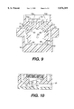
- FIG. 9 is a cutaway view taken along lines 9--9 of FIG. 5;
- FIG. 10 is a partial cutaway elevation view taken along lines 10--10 of FIG. 6;
- FIG. 11 is a block diagram of the electronic circuitry of the invention.
- FIG. 12 is a cutaway elevation view of the two-way solenoid valve.
- FIG. 13 is a cutaway elevation view of the three-way solenoid valve.
- the controller is illustrated in FIGS. 1 and 2 and includes a compact readily transportable housing 10.
- a control or front panel 12 is provided on the front of the housing and includes controls and indicators for system operation.
- the control panel includes a display 14 which typically is an LED display to provide messages and indications to an operator.
- the panel also includes a cooling mode switch 16.
- the switch is preferably a membrane type switch actuated by finger pressure on the switch area delineated on the front panel.
- the front panel also includes visual indicators, preferably light emitting diodes (LED's) (not shown) to indicate inflation and cooling modes.
- An air grill 20 is provided on a side of the housing by which cooling air is drawn into the housing by a fan 22 disposed proximate to the grill.
- a fan filter 24 is interposed between the grill and fan for filtering dust and other particles from the input air.
- the grill and filter element are readily removable for cleaning or replacement of the filter.
- An output connector 26 is disposed on the rear of the housing and is adapted to be connected to a mating connector of a tubing set by which the controller is connected to one or more compression sleeves.
- the housing includes a handle 28 in which a sound muffler 30 (FIG.
- the housing can be interiorly lined with acoustic foam 32 to further reduce operating noise.
- a power cord 34 extends from the side of the housing opposite to the input air grill, and a power switch 36 is provided adjacent to the power cord on the housing side.
- a bracket 38 is provided on the rear of the panel having a lower element 40 co-planar with the bottom surface of the housing and providing a hook by which the housing can be suspended from the foot board of a patient's bed.
- the housing can be placed on a floor or other supporting surface.
- the compressor 31 directly connected to a variable speed DC motor 42 and having an inlet air tube 44 coupled to muffler 30, and an outlet air tube 46 coupled via air filter 48 to the input of manifold assembly 50.
- the motor is preferably a three phase brushless DC motor which is controllable by a solid state control circuit for providing fine speed control.
- the compressor is preferably a rotary vane compressor which operates at a high speed, typically 1000 rpm, and which is driven at a speed governed by the speed of motor 42 to provide intended output pressure.
- the pump can be a diaphragm pump.
- the speed of the motor 42 is electronically controlled to provide a corresponding compressor speed for respective output pressures as desired.
- a pressure transducer 52 is coupled via tubing 54 to the manifold assembly 50 for monitoring output pressure.
- a power supply board 56 is connected to the motor 42 via a ribbon cable 58, and is also connected via a ribbon cable 60 to the processor board 62. Electrical power is provided to the system via a transformer 63.
- the manifold assembly 50 is shown in detail in FIGS. 5 through 10 and comprises a unitary housing 64 which is typically fabricated of molded plastic, and having an input port 66, a transducer port 68 coupled to pressure sensor 52, and output ports 70a through 70d which are coupled to respective ports 80 of valve structures 82.
- Each of the valve structures has an associated solenoid 84 which is electrically driven via the processor on board 62.
- the solenoid is coupled to a valve seat which is threaded into the cooperative threaded opening in housing 64, the seat being operative to open and close the respective valve upon actuation of the solenoid.
- Each of the valve structures 82 includes a cavity 81 having a central port or opening 80 in a surrounding valve seat, and a second opening 83 in the valve cavity.
- the central openings 80 of the valve cavities are in fluid communication with a chamber 85 in the housing and beneath the valve cavities, this chamber also being in communication with inlet port 66.
- the second openings 83 of the valve cavities are coupled to respective ports 70a-70d of the connector 26 via passages 71.
- a transducer port 68 is provided in communication with one of the output ports and adapted for coupling to a pressure sensor (FIG. 4) operative to monitor sleeve pressure when the compression system is assembled with the compression sleeves, interconnecting tubing and controller.
- the pressure sensor monitors the pressure in the ankle channel. Monitoring could be provided in any other channel or in multiple channels.
- FIGS. 12 and 13 a solenoid 84 and associated valve components are mounted on each valve cavity 81.
- each of the solenoids is threadably retained in the respective valve cavity 81 by cooperative threads on the periphery of the valve cavity and associated threaded fitting (not shown) on the solenoid structure.
- FIGS. 12 and 13 illustrate an alternative mechanism for retaining the solenoids in the valve cavities.
- the solenoid structure includes a coaxially disposed plunger 90 having a seal 91 which in the downward or depressed position seats over the central port 80 to stop fluid flow therethrough.
- the plunger is operated by the solenoid coil 92. When the seal is in a raised or open position, fluid can flow from the central opening 80 and thence through the second opening 83 to the corresponding port 70 of the output connector 26.
- the valve 84 connected to the cooling port 70b of the output connector is a two-way, normally closed valve, shown in FIG. 12.
- normally closed no air is provided to the cooling port of the connector.
- the valve is actuated and the valve is open, air is permitted to flow to the cooling port of the connector and thence to the cooling channels of the compression sleeves.
- the other valves are three-way normally closed valves, as shown in FIG. 13, which have a coaxial port or opening 85 through the top of the solenoid structure which communicates with the annular space between the plunger 90 and the surrounding wall.
- the open position air flows from the center port 80 to the second port 83 and thence to the associated output port 70 of the connector 26 and into the compression sleeves.
- the center port 80 In the closed position, the center port 80 is blocked by the depressed valve seal 91 and air from the sleeve chambers flows back through the connector port 70 and through the second opening 83 and out the vent port 85 of the associated valve.
- valves 84 associated with output ports 70a, 70c, and 70d are operated in sequence to pressurize the ankle, calf and thigh chambers of the compression sleeves and provide sequential pressurization of the chambers and venting of the chambers under the control of the microprocessor.
- the solenoid 84 for the cooling output port 70b is selectively actuated when cooling operation is desired.
- Each of the solenoids is driven by pulse width modulated signals provided by the control circuit 108.
- the solenoid drive signals are at a first higher power level for rapid and positive actuation of the solenoid valves. After initial actuation, the valves are maintained in an actuated state by drive signals of a second lower power level, thereby to reduce power consumption.
- the first higher level drive signals have a duty cycle of 87%, while the second lower drive signals have a duty cycle of 75%.
- the manifold assembly provides a compact pneumatic assembly which eliminates more complex conventional assemblies of separate valves, fittings and tubing.
- the unitary manifold assembly permits the controller to be very compact and easily transportable, and also provides a highly reliable structure which requires only a single input fitting and output connector and a sensor port.
- the output ports 70a, 70c, and 70d are coupled via the mating connector and tubing set (not shown) to the multi-chamber compression sleeves adapted to fit around the legs of a patient.
- the solenoid valves are sequentially energized to pressurize, in sequence, the ankle, calf and thigh chambers of both sleeves.
- the solenoid valves are simultaneously de-energized to disconnect the compressor from the sleeves and to allow the valves to vent sleeve pressure to the atmosphere via the vent ports 85 on the manifold assembly.
- the pressure transducer 52 monitors the pressure at the ankle portion of the pneumatic circuit and provides an electrical signal input to the microprocessor for purposes of feedback control.
- the ventilation or cooling port 70b of the manifold assembly 50 is coupled via the corresponding tube of the tubing set to the ventilation or cooling opening of the sleeves to provide air flow through the sleeve walls for cooling purposes when the cooling mode is activated by front panel control 16.
- the solenoid valve coupled to the vent port 70b of the manifold assembly 50 is a two-way normally closed valve. When energized, air is passed from the compressor 31 to the ventilation or cooling port 70b and thence to the ventilation tubing of the sleeves. When de-energized, flow is blocked.
- the other solenoid valves are three-way normally closed valves. When in an open position, these valves allow passage of air from the compressor 31 to the respective output ports 70a, 70c, and 70d. When de-energized and therefor in a closed position, the compressor air is blocked and air pressure in the sleeves is released through the venting ports 85 on top of the associated solenoid valves. When the cooling mode is off, the compressor 31 can be turned off during the vent portion of a cycle.
- the solenoid valves are driven in a two-stage manner with a higher power drive signal provided to initially energize the valves and a lower power signal thereafter provided to maintain or hold the valves in an energized state.
- the solenoid valves and the DC motor are driven by pulse width modulated (PWM) electrical signals generated by the control circuitry.
- PWM pulse width modulated
- a power supply 100 provides electrical power to the control processor 102 which receives an input from pressure sensor 52 and from controls 104.
- the controller processor 102 provides output signals to motor control circuit 106 which in turn provides drive signals to motor 42.
- the control processor 102 also provides output signals to control circuit 108 which provides drive signals to solenoid valves 84.
- Indicators 110 are also driven by output signals from the control processor 102.
- the motor control circuit 106 Under the control of processor 102, the motor control circuit 106 provides pulse width modulated signals to motor 42, the modulation being varied to control the speed of the motor and corresponding speed of the compressor 31 to provide intended output pressure.
- the solenoid valve control circuit 108 provides pulse width modulated signals to the solenoid valves 84 for energizing the valves.
- the valves are driven in a two-stage manner, with a higher power drive signal provided by control circuit 108 to initially energize the valve, and a lower power signal thereafter provided by control circuit 108 to maintain the valve in its energized state.
- Fault conditions are detected and processed by the control processor 102, and upon such detection normal operation of the system is interrupted by closure of all solenoid valves 84, and with the appropriate fault code being displayed on the front panel display 14 and an audible alarm also sounded via an audible indicator 15 mounted beneath the front panel.
- the control processor includes an automatic restart circuit which will be activated to initiate a resetting or restarting operation. If upon such restarting, the cause of the malfunction or fault is still present, the system will typically continue to attempt to restart and during such restarting attempts, the audible alarm will beep.
- the system can be implemented such that after a predetermined period of time or number of restart attempts, the system will shut down under command from processor 102, if a fault condition remains.
- the system operates in the following manner.
- a series of self-tests are conducted under government of the processor 102. All of the LED indicators are illuminated and the beeper is sounded for about 1/2 second to verify the operability of the visual and audible indicators.
- the multi-segment display is illuminated to verify display operability.
- the cycle monitor LEDs inflate and vent
- the cooling LED illuminates momentarily.
- the pre-set pressure typically 45 mmHg is displayed and the compressor speed is adjusted to provide the predetermined start pressure for ankle inflation.
- the system then commences the inflation cycle for sequential inflation of the ankle, calf and thigh chambers of the attached compression sleeves.
- the system is also operative in a pressure monitor mode by which an operator can read displayed actual pressure.
- This mode is actuated by a front panel control 17 which is a touch sensitive area of the front panel.
- a decimal point or other portion of the display will flash to indicate that actual pressure is being displayed.
- the displayed pressure is the pre-set pressure.
- the system will maintain the pre-set pressure automatically by feedback control governed by the processor.
- the fault messages indicate abnormal pressure or absence of pressure to the connected tubing and sleeves and diagnostic messages indicating conditions requiring system repair.
Abstract
Description
Claims (13)
Priority Applications (1)
| Application Number | Priority Date | Filing Date | Title |
|---|---|---|---|
| US08/338,310 US5876359A (en) | 1994-11-14 | 1994-11-14 | Sequential compression device controller |
Applications Claiming Priority (1)
| Application Number | Priority Date | Filing Date | Title |
|---|---|---|---|
| US08/338,310 US5876359A (en) | 1994-11-14 | 1994-11-14 | Sequential compression device controller |
Publications (1)
| Publication Number | Publication Date |
|---|---|
| US5876359A true US5876359A (en) | 1999-03-02 |
Family
ID=23324282
Family Applications (1)
| Application Number | Title | Priority Date | Filing Date |
|---|---|---|---|
| US08/338,310 Expired - Lifetime US5876359A (en) | 1994-11-14 | 1994-11-14 | Sequential compression device controller |
Country Status (1)
| Country | Link |
|---|---|
| US (1) | US5876359A (en) |
Cited By (90)
| Publication number | Priority date | Publication date | Assignee | Title |
|---|---|---|---|---|
| WO2000049968A2 (en) * | 1999-02-26 | 2000-08-31 | Kci Licensing, Inc. | Portable pump for use with gradient compression bandage |
| US6231532B1 (en) * | 1998-10-05 | 2001-05-15 | Tyco International (Us) Inc. | Method to augment blood circulation in a limb |
| US6290662B1 (en) * | 1999-05-28 | 2001-09-18 | John K. Morris | Portable, self-contained apparatus for deep vein thrombosis (DVT) prophylaxis |
| US6440093B1 (en) * | 1996-04-29 | 2002-08-27 | Mcewen James Allen | Apparatus and method for monitoring pneumatic limb compression therapy |
| US6629941B1 (en) * | 1998-12-28 | 2003-10-07 | Nitto Kohki Co., Ltd. | Air massage system |
| US6648840B2 (en) * | 1996-08-02 | 2003-11-18 | Salton, Inc. | Microcontroller based massage system |
| US20040064192A1 (en) * | 2002-09-27 | 2004-04-01 | Bubb Stephen K. | Porous implant system and treatment method |
| US6736787B1 (en) | 1996-04-29 | 2004-05-18 | Mcewen James Allen | Apparatus for applying pressure waveforms to a limb |
| US20040127937A1 (en) * | 1998-07-25 | 2004-07-01 | Newton Michael David | Identification and communication system for inflatable devices |
| US20040193078A1 (en) * | 2003-03-26 | 2004-09-30 | Flick Roland E. | Vibrational and pulsating cushioning device |
| WO2004091463A2 (en) * | 2003-04-11 | 2004-10-28 | Hill-Rom Services, Inc. | System for compression therapy |
| US20050033351A1 (en) * | 1998-07-25 | 2005-02-10 | Newton Michael David | Identification and communication system for inflatable devices |
| US6881044B1 (en) | 2003-10-31 | 2005-04-19 | Gast Manufacturing Corporation | Rotary vane compressor with interchangeable end plates |
| US20050107725A1 (en) * | 2003-03-27 | 2005-05-19 | Wild David G. | Compression device for the limb |
| US20050187503A1 (en) * | 2004-02-23 | 2005-08-25 | Elise Tordella | Compression apparatus |
| US20050187499A1 (en) * | 2004-02-23 | 2005-08-25 | Heather Gillis | Compression apparatus |
| US20050222526A1 (en) * | 2004-02-23 | 2005-10-06 | Tyco Healthcare Group Lp | Garment detection method and system for delivering compression treatment |
| US20060027228A1 (en) * | 2004-07-21 | 2006-02-09 | Moss Edward P | Glass-lined vertical steam smoker evince |
| US20060083623A1 (en) * | 2004-10-08 | 2006-04-20 | Mark Higgins | Compression pump system |
| US7044924B1 (en) | 2000-06-02 | 2006-05-16 | Midtown Technology | Massage device |
| US20060135894A1 (en) * | 2004-10-21 | 2006-06-22 | Bristol-Myers Squibb Company | Compression device for the limb |
| US20070038167A1 (en) * | 2005-06-08 | 2007-02-15 | Bristol-Myers Squibb Company | Compression device for the foot |
| US20070088239A1 (en) * | 2000-06-02 | 2007-04-19 | Midtown Technology Ltd. | Inflatable massage garment |
| EP1795168A1 (en) | 2005-12-12 | 2007-06-13 | Tyco Healthcare Group LP | Compression apparatus |
| US20070142731A1 (en) * | 2005-12-20 | 2007-06-21 | Shenzhen Mindray Bio-Medical Electronics Co., Ltd | Non-invasive electronic method and apparatus for measuring blood pressure |
| US20070249976A1 (en) * | 2006-01-24 | 2007-10-25 | Bristol-Myers Squibb Company | Proximity detection apparatus |
| US20080064992A1 (en) * | 2006-09-08 | 2008-03-13 | Stewart Thomas P | Heat transfer cuff |
| US20080092295A1 (en) * | 2003-03-26 | 2008-04-24 | Gaymar Industries, Inc. | Vibrational and Pulsating Cushioning Device |
| US20080249447A1 (en) * | 2007-04-09 | 2008-10-09 | Tyco Healthcare Group Lp | Compression Device Having Cooling Capability |
| US20080249449A1 (en) * | 2007-04-09 | 2008-10-09 | Tyco Healthcare Group Lp | Methods of Making Compression Device with Improved Evaporation |
| US20080249455A1 (en) * | 2007-04-09 | 2008-10-09 | Tyco Healthcare Group Lp | Compression Device with Improved Moisture Evaporation |
| US20080249440A1 (en) * | 2007-04-09 | 2008-10-09 | Tyco Healthcare Group Lp | Method of Making Compression Sleeve with Structural Support Features |
| EP1980230A1 (en) | 2007-04-09 | 2008-10-15 | Covidien AG | Compression device with S-shaped bladder |
| EP1980232A1 (en) | 2007-04-09 | 2008-10-15 | Covidien AG | Compression device with structural support features |
| EP1980231A2 (en) | 2007-04-09 | 2008-10-15 | Covidien AG | Compression device having weld seam moisture transfer |
| US20090009290A1 (en) * | 2007-07-05 | 2009-01-08 | Baxter International Inc. | Radio frequency auto-identification system |
| US7490620B2 (en) | 2004-02-23 | 2009-02-17 | Tyco Healthcare Group Lp | Fluid conduit connector apparatus |
| EP2058577A2 (en) | 2007-11-08 | 2009-05-13 | Tyco Healthcare Group LP | Telescopingly adjustable clamp |
| US20090177222A1 (en) * | 2007-04-09 | 2009-07-09 | Tyco Healthcare Group Lp | Compression Device with Improved Moisture Evaporation |
| US20090240178A1 (en) * | 2008-03-20 | 2009-09-24 | Tyco Healthcare Group Lp | Safety connector assembly |
| US20090270910A1 (en) * | 2006-05-19 | 2009-10-29 | The Regents Of The University Of California | Method and Apparatus for Increasing Blood Flow in a Body Part |
| USD608006S1 (en) | 2007-04-09 | 2010-01-12 | Tyco Healthcare Group Lp | Compression device |
| EP2168555A1 (en) | 2008-09-30 | 2010-03-31 | Tyco Healthcare Group LP | Compression Device with Wear Area |
| EP2168554A1 (en) | 2008-09-30 | 2010-03-31 | Tyco Healthcare Group LP | Compression Device with Removable Portion |
| US20100189578A1 (en) * | 2009-01-26 | 2010-07-29 | Tyco Healthcare Group Lp | Mount for a compression control unit |
| US20110066091A1 (en) * | 2004-10-11 | 2011-03-17 | Convatec Technologies Inc. | Electro active compression bandage |
| US7931651B2 (en) | 2006-11-17 | 2011-04-26 | Wake Lake University Health Sciences | External fixation assembly and method of use |
| EP2314268A2 (en) | 2004-02-23 | 2011-04-27 | Tyco Healthcare Group LP | Compression treatment system |
| US8029450B2 (en) | 2007-04-09 | 2011-10-04 | Tyco Healthcare Group Lp | Breathable compression device |
| US8029451B2 (en) | 2005-12-12 | 2011-10-04 | Tyco Healthcare Group Lp | Compression sleeve having air conduits |
| EP2371330A2 (en) | 2010-04-02 | 2011-10-05 | Tyco Healthcare Group, LP | Compression garment having an extension |
| US8034007B2 (en) | 2007-04-09 | 2011-10-11 | Tyco Healthcare Group Lp | Compression device with structural support features |
| EP2428192A2 (en) | 2010-09-14 | 2012-03-14 | Tyco Healthcare Group LP | Compression sleeve with improved position retention |
| EP2431018A1 (en) | 2010-09-21 | 2012-03-21 | Tyco Healthcare Group LP | Bladder tube connection |
| USD659839S1 (en) | 2010-08-16 | 2012-05-15 | Tyco Healthcare Group Lp | Support for a pneumatic compression controller |
| US20120209153A1 (en) * | 2011-02-14 | 2012-08-16 | Farrow Mark A | Deep vein thrombosis therapy device |
| US8257286B2 (en) | 2006-09-21 | 2012-09-04 | Tyco Healthcare Group Lp | Safety connector apparatus |
| US8267960B2 (en) | 2008-01-09 | 2012-09-18 | Wake Forest University Health Sciences | Device and method for treating central nervous system pathology |
| USD675741S1 (en) | 2010-08-16 | 2013-02-05 | Covidien Lp | Pneumatic compression controller |
| US8377016B2 (en) | 2007-01-10 | 2013-02-19 | Wake Forest University Health Sciences | Apparatus and method for wound treatment employing periodic sub-atmospheric pressure |
| EP2574320A1 (en) | 2011-09-30 | 2013-04-03 | Covidien LP | Compression Sleeve |
| US8539647B2 (en) | 2005-07-26 | 2013-09-24 | Covidien Ag | Limited durability fastening for a garment |
| US20130317538A1 (en) * | 2008-05-21 | 2013-11-28 | Robert J. Perry | Vein presentation enhancement device |
| US8636678B2 (en) | 2008-07-01 | 2014-01-28 | Covidien Lp | Inflatable member for compression foot cuff |
| US20140094725A1 (en) * | 2012-09-28 | 2014-04-03 | Covidien Lp | Residual pressure control in a compression device |
| US8734370B1 (en) * | 2007-05-14 | 2014-05-27 | Mario Battiste Ignagni | Device for clearing mucus from the pulmonary system |
| US8834520B2 (en) | 2007-10-10 | 2014-09-16 | Wake Forest University | Devices and methods for treating spinal cord tissue |
| US8845562B2 (en) | 2010-07-21 | 2014-09-30 | Hill-Rom Services, Inc. | Gas supply system |
| US20140303533A1 (en) * | 2013-03-15 | 2014-10-09 | Innovamed Health, LLC | Portable intermittent pneumatic compression system |
| US20150216760A1 (en) * | 2014-02-04 | 2015-08-06 | Joseph Thomas Adams | Multi-Port Connection and Multi-Port Multiple Outlet Manifold |
| USD737447S1 (en) * | 2013-10-31 | 2015-08-25 | Mego Afek Ac Ltd. | Device for medical treatment |
| US9125787B2 (en) | 2011-09-30 | 2015-09-08 | Covidien Lp | Compression garment having a foam layer |
| US9205021B2 (en) | 2012-06-18 | 2015-12-08 | Covidien Lp | Compression system with vent cooling feature |
| US9248074B2 (en) | 2006-01-13 | 2016-02-02 | Swelling Solutions, Inc. | Device, system and method for compression treatment of a body part |
| US9289193B2 (en) | 2008-07-18 | 2016-03-22 | Wake Forest University Health Sciences | Apparatus and method for cardiac tissue modulation by topical application of vacuum to minimize cell death and damage |
| US9402779B2 (en) | 2013-03-11 | 2016-08-02 | Covidien Lp | Compression garment with perspiration relief |
| US9737454B2 (en) | 2012-03-02 | 2017-08-22 | Hill-Rom Services, Inc. | Sequential compression therapy compliance monitoring systems and methods |
| US20180125744A1 (en) * | 2016-11-08 | 2018-05-10 | Lear Corporation | Seat Assembly Having Massage Bladders with Reduced Pressure Sensor Count |
| US10434033B2 (en) | 2017-11-01 | 2019-10-08 | Vena Group, LLC | Portable, reusable, and disposable intermittent pneumatic compression system |
| USD868957S1 (en) * | 2017-09-29 | 2019-12-03 | Tactile Systems Technology, Inc. | Pump controller |
| US10507158B2 (en) | 2016-02-18 | 2019-12-17 | Hill-Rom Services, Inc. | Patient support apparatus having an integrated limb compression device |
| US10562436B2 (en) * | 2013-07-30 | 2020-02-18 | Signode Industrial Group Llc | Portable dunnage bag inflator |
| US10639230B2 (en) * | 2018-04-29 | 2020-05-05 | Luraco, Inc. | Massage chair having a mechanism for adjusting position of fluid massage element for arm massaging |
| US10724549B2 (en) | 2017-05-11 | 2020-07-28 | Luraco, Inc. | Massage chair having a noise-reducing, enclosure device |
| US10842708B2 (en) | 2017-01-25 | 2020-11-24 | Luraco, Inc. | Massage apparatus for legs and feet and massage chair having the massage apparatus |
| US11058226B2 (en) | 2016-12-08 | 2021-07-13 | Intex Marketing Ltd. | Recessed air pump |
| US11179290B2 (en) | 2017-05-11 | 2021-11-23 | Luraco, Inc. | Massage chair having a wireless charger, armrest sliding, hammering devices, and oxygen generation |
| US11471116B2 (en) | 2006-01-24 | 2022-10-18 | Swelling Solutions, Inc. | Control unit assembly |
| USD979608S1 (en) | 2020-05-26 | 2023-02-28 | Signode Industrial Group Llc | Inflator |
| US11654075B2 (en) * | 2019-03-29 | 2023-05-23 | Hill-Rom Sevices, Inc. | Method and apparatus for upgrading a patient support apparatus to include an integrated patient therapy device |
Citations (7)
| Publication number | Priority date | Publication date | Assignee | Title |
|---|---|---|---|---|
| US4013039A (en) * | 1976-09-02 | 1977-03-22 | International Business Machines Corporation | Wet processing PH control |
| US4029087A (en) * | 1975-10-28 | 1977-06-14 | The Kendall Company | Extremity compression device |
| US4375217A (en) * | 1980-06-04 | 1983-03-01 | The Kendall Company | Compression device with pressure determination |
| US4396010A (en) * | 1980-06-30 | 1983-08-02 | The Kendall Company | Sequential compression device |
| US4521167A (en) * | 1981-06-11 | 1985-06-04 | Cavalleri Robert J | Low frictional loss rotary vane gas compressor having superior lubrication characteristics |
| US4583255A (en) * | 1983-03-05 | 1986-04-22 | Nitto Kohki Co., Ltd. | Massage arrangement of the pneumatic type |
| US4957107A (en) * | 1988-05-10 | 1990-09-18 | Sipin Anatole J | Gas delivery means |
-
1994
- 1994-11-14 US US08/338,310 patent/US5876359A/en not_active Expired - Lifetime
Patent Citations (7)
| Publication number | Priority date | Publication date | Assignee | Title |
|---|---|---|---|---|
| US4029087A (en) * | 1975-10-28 | 1977-06-14 | The Kendall Company | Extremity compression device |
| US4013039A (en) * | 1976-09-02 | 1977-03-22 | International Business Machines Corporation | Wet processing PH control |
| US4375217A (en) * | 1980-06-04 | 1983-03-01 | The Kendall Company | Compression device with pressure determination |
| US4396010A (en) * | 1980-06-30 | 1983-08-02 | The Kendall Company | Sequential compression device |
| US4521167A (en) * | 1981-06-11 | 1985-06-04 | Cavalleri Robert J | Low frictional loss rotary vane gas compressor having superior lubrication characteristics |
| US4583255A (en) * | 1983-03-05 | 1986-04-22 | Nitto Kohki Co., Ltd. | Massage arrangement of the pneumatic type |
| US4957107A (en) * | 1988-05-10 | 1990-09-18 | Sipin Anatole J | Gas delivery means |
Non-Patent Citations (2)
| Title |
|---|
| International Publication No: WO 93/12708 (Inventor: LINA, Cesar, Z.), Dec. 1991. * |
| Kend EP 000542383 A2, May 1993. * |
Cited By (194)
| Publication number | Priority date | Publication date | Assignee | Title |
|---|---|---|---|---|
| US6440093B1 (en) * | 1996-04-29 | 2002-08-27 | Mcewen James Allen | Apparatus and method for monitoring pneumatic limb compression therapy |
| US6736787B1 (en) | 1996-04-29 | 2004-05-18 | Mcewen James Allen | Apparatus for applying pressure waveforms to a limb |
| US6648840B2 (en) * | 1996-08-02 | 2003-11-18 | Salton, Inc. | Microcontroller based massage system |
| US20040127937A1 (en) * | 1998-07-25 | 2004-07-01 | Newton Michael David | Identification and communication system for inflatable devices |
| US6884255B1 (en) * | 1998-07-25 | 2005-04-26 | Huntleigh Technology, Plc | Identification and communication system for inflatable devices |
| US7398803B2 (en) | 1998-07-25 | 2008-07-15 | Huntleigh Technology Ltd | Identification and communication system for inflatable devices |
| US20050033351A1 (en) * | 1998-07-25 | 2005-02-10 | Newton Michael David | Identification and communication system for inflatable devices |
| US6231532B1 (en) * | 1998-10-05 | 2001-05-15 | Tyco International (Us) Inc. | Method to augment blood circulation in a limb |
| US6629941B1 (en) * | 1998-12-28 | 2003-10-07 | Nitto Kohki Co., Ltd. | Air massage system |
| WO2000049968A3 (en) * | 1999-02-26 | 2001-07-05 | Kci Licensing Inc | Portable pump for use with gradient compression bandage |
| WO2000049968A2 (en) * | 1999-02-26 | 2000-08-31 | Kci Licensing, Inc. | Portable pump for use with gradient compression bandage |
| US6290662B1 (en) * | 1999-05-28 | 2001-09-18 | John K. Morris | Portable, self-contained apparatus for deep vein thrombosis (DVT) prophylaxis |
| US7771376B2 (en) | 2000-06-02 | 2010-08-10 | Midtown Technology Ltd. | Inflatable massage garment |
| US20070088239A1 (en) * | 2000-06-02 | 2007-04-19 | Midtown Technology Ltd. | Inflatable massage garment |
| US7044924B1 (en) | 2000-06-02 | 2006-05-16 | Midtown Technology | Massage device |
| US6840960B2 (en) * | 2002-09-27 | 2005-01-11 | Stephen K. Bubb | Porous implant system and treatment method |
| US20040064192A1 (en) * | 2002-09-27 | 2004-04-01 | Bubb Stephen K. | Porous implant system and treatment method |
| US7322947B2 (en) | 2003-03-26 | 2008-01-29 | Gaymar Industries, Inc. | Vibrational and pulsating cushioning device |
| US20080092295A1 (en) * | 2003-03-26 | 2008-04-24 | Gaymar Industries, Inc. | Vibrational and Pulsating Cushioning Device |
| US8038632B2 (en) | 2003-03-26 | 2011-10-18 | Stryker Corporation | Vibrational and pulsating cushion device |
| US20080097259A1 (en) * | 2003-03-26 | 2008-04-24 | Gaymar Industries, Inc. | Vibrational and Pulsating Cushion Device |
| US20040193078A1 (en) * | 2003-03-26 | 2004-09-30 | Flick Roland E. | Vibrational and pulsating cushioning device |
| US20050107725A1 (en) * | 2003-03-27 | 2005-05-19 | Wild David G. | Compression device for the limb |
| US9539166B2 (en) | 2003-03-27 | 2017-01-10 | Swelling Solutions, Inc. | Compression device for the limb |
| US10772790B2 (en) | 2003-03-27 | 2020-09-15 | Tactile Systems Technology Inc. | Compression device for the limb |
| US9044372B2 (en) | 2003-03-27 | 2015-06-02 | Swelling Solutions, Inc. | Compression device for the limb |
| US9220655B2 (en) | 2003-04-11 | 2015-12-29 | Hill-Rom Services, Inc. | System for compression therapy |
| US20060258964A1 (en) * | 2003-04-11 | 2006-11-16 | Biondo John P | System for compression therapy |
| WO2004091463A2 (en) * | 2003-04-11 | 2004-10-28 | Hill-Rom Services, Inc. | System for compression therapy |
| WO2004091463A3 (en) * | 2003-04-11 | 2005-02-17 | Hill Rom Services Inc | System for compression therapy |
| US20100076356A1 (en) * | 2003-04-11 | 2010-03-25 | Biondo John P | System for compression therapy |
| US6881044B1 (en) | 2003-10-31 | 2005-04-19 | Gast Manufacturing Corporation | Rotary vane compressor with interchangeable end plates |
| US7282038B2 (en) | 2004-02-23 | 2007-10-16 | Tyco Healthcare Group Lp | Compression apparatus |
| EP2319476A2 (en) | 2004-02-23 | 2011-05-11 | Tyco Healthcare Group LP | Compression treatment system |
| US20100276619A1 (en) * | 2004-02-23 | 2010-11-04 | Tyco Healthcare Group Lp | Fluid conduit connector apparatus |
| US20100249679A1 (en) * | 2004-02-23 | 2010-09-30 | Tyco Healthcare Group Lp | Garment Detection Method and System for Delivering Compression Treatment |
| US7354411B2 (en) | 2004-02-23 | 2008-04-08 | Tyco Healthcare Group Lp | Garment detection method and system for delivering compression treatment |
| US7354410B2 (en) | 2004-02-23 | 2008-04-08 | Tyco Healthcare Group Lp | Compression treatment system |
| US7871387B2 (en) | 2004-02-23 | 2011-01-18 | Tyco Healthcare Group Lp | Compression sleeve convertible in length |
| EP2314268A2 (en) | 2004-02-23 | 2011-04-27 | Tyco Healthcare Group LP | Compression treatment system |
| US20080103422A1 (en) * | 2004-02-23 | 2008-05-01 | Tyco Healthcare Group Lp | Garment Detection Method and System for Delivering Compression Treatment |
| US7810519B2 (en) | 2004-02-23 | 2010-10-12 | Tyco Healthcare Group Lp | Fluid conduit connector apparatus |
| US8256459B2 (en) | 2004-02-23 | 2012-09-04 | Tyco Healthcare Group Lp | Fluid conduit connector apparatus |
| US8734369B2 (en) * | 2004-02-23 | 2014-05-27 | Covidien Lp | Garment detection method and system for delivering compression treatment |
| US7490620B2 (en) | 2004-02-23 | 2009-02-17 | Tyco Healthcare Group Lp | Fluid conduit connector apparatus |
| US20050187503A1 (en) * | 2004-02-23 | 2005-08-25 | Elise Tordella | Compression apparatus |
| US20050222526A1 (en) * | 2004-02-23 | 2005-10-06 | Tyco Healthcare Group Lp | Garment detection method and system for delivering compression treatment |
| US20050187499A1 (en) * | 2004-02-23 | 2005-08-25 | Heather Gillis | Compression apparatus |
| US9782323B2 (en) | 2004-02-23 | 2017-10-10 | Covidien Lp | Garment detection method and system for delivering compression treatment |
| US20090146092A1 (en) * | 2004-02-23 | 2009-06-11 | Tyco Healthcare Group Lp | Fluid conduit connector apparatus |
| US20060027228A1 (en) * | 2004-07-21 | 2006-02-09 | Moss Edward P | Glass-lined vertical steam smoker evince |
| US20060083623A1 (en) * | 2004-10-08 | 2006-04-20 | Mark Higgins | Compression pump system |
| US10071012B2 (en) | 2004-10-11 | 2018-09-11 | Swelling Solutions, Inc. | Electro active compression bandage |
| US20110066091A1 (en) * | 2004-10-11 | 2011-03-17 | Convatec Technologies Inc. | Electro active compression bandage |
| US8517963B2 (en) | 2004-10-11 | 2013-08-27 | Swelling Solutions, Inc. | Electro active compression bandage |
| US20060135894A1 (en) * | 2004-10-21 | 2006-06-22 | Bristol-Myers Squibb Company | Compression device for the limb |
| US8636679B2 (en) | 2004-10-21 | 2014-01-28 | Swelling Solutions, Inc. | Compression device for the limb |
| US9463135B2 (en) | 2005-06-08 | 2016-10-11 | Swelling Solutions, Inc. | Compression device for the foot |
| US9278043B2 (en) | 2005-06-08 | 2016-03-08 | Swelling Solutions, Inc. | Cuff for providing compression to a limb |
| US20070049852A1 (en) * | 2005-06-08 | 2007-03-01 | Bristol-Myers Squibb Company | A cuff for providing compression to a limb |
| US11154451B2 (en) | 2005-06-08 | 2021-10-26 | Swelling Solutions, Inc. | Compression device for the foot |
| US20070038167A1 (en) * | 2005-06-08 | 2007-02-15 | Bristol-Myers Squibb Company | Compression device for the foot |
| US8574180B2 (en) | 2005-06-08 | 2013-11-05 | Swelling Solutions, Inc. | Compression device for the foot |
| US9364037B2 (en) | 2005-07-26 | 2016-06-14 | Covidien Ag | Limited durability fastening for a garment |
| US8539647B2 (en) | 2005-07-26 | 2013-09-24 | Covidien Ag | Limited durability fastening for a garment |
| US8029451B2 (en) | 2005-12-12 | 2011-10-04 | Tyco Healthcare Group Lp | Compression sleeve having air conduits |
| US20070135743A1 (en) * | 2005-12-12 | 2007-06-14 | Ann Meyer | Compression apparatus |
| EP1795168A1 (en) | 2005-12-12 | 2007-06-13 | Tyco Healthcare Group LP | Compression apparatus |
| US7931606B2 (en) | 2005-12-12 | 2011-04-26 | Tyco Healthcare Group Lp | Compression apparatus |
| US8079970B2 (en) | 2005-12-12 | 2011-12-20 | Tyco Healthcare Group Lp | Compression sleeve having air conduits formed by a textured surface |
| US7988636B2 (en) | 2005-12-20 | 2011-08-02 | Shenzhen Mindray Bio-Medical Electronics Co., Ltd. | Non-invasive electronic apparatus for measuring blood pressure |
| US20100094145A1 (en) * | 2005-12-20 | 2010-04-15 | Shenzhen Mindray Bio-Medical Electronics Co., Ltd. | Non-invasive electronic apparatus for measuring blood pressure |
| US20070142731A1 (en) * | 2005-12-20 | 2007-06-21 | Shenzhen Mindray Bio-Medical Electronics Co., Ltd | Non-invasive electronic method and apparatus for measuring blood pressure |
| US20090137913A1 (en) * | 2005-12-20 | 2009-05-28 | Shenzhen Mindray Bio-Medical Electronics Co., Ltd. | Non-invasive electronic method and apparatus for measuring blood pressure |
| US7468038B2 (en) * | 2005-12-20 | 2008-12-23 | Shenzhen Mindray Bio-Medical Electronics Co., Ltd. | Non-invasive electronic method and apparatus for measuring blood pressure |
| US7981043B2 (en) | 2005-12-20 | 2011-07-19 | Shenzhen Mindray Bio-Medical Electronics Co., Ltd. | Non-invasive electronic method and apparatus for measuring blood pressure |
| US10828220B2 (en) | 2006-01-13 | 2020-11-10 | Tactile Systems Technology Inc. | Device, system and method for compression treatment of a body part |
| US9248074B2 (en) | 2006-01-13 | 2016-02-02 | Swelling Solutions, Inc. | Device, system and method for compression treatment of a body part |
| US11471116B2 (en) | 2006-01-24 | 2022-10-18 | Swelling Solutions, Inc. | Control unit assembly |
| US10092250B2 (en) | 2006-01-24 | 2018-10-09 | Swelling Solutions, Inc. | Control unit for a medical device |
| US20070249976A1 (en) * | 2006-01-24 | 2007-10-25 | Bristol-Myers Squibb Company | Proximity detection apparatus |
| US20090270910A1 (en) * | 2006-05-19 | 2009-10-29 | The Regents Of The University Of California | Method and Apparatus for Increasing Blood Flow in a Body Part |
| US7972287B2 (en) | 2006-09-08 | 2011-07-05 | Gaymar Industries, Inc. | Heat transfer cuff |
| US20080064992A1 (en) * | 2006-09-08 | 2008-03-13 | Stewart Thomas P | Heat transfer cuff |
| US9687249B2 (en) | 2006-09-21 | 2017-06-27 | Covidien Lp | Safety connector assembly |
| US8287517B2 (en) | 2006-09-21 | 2012-10-16 | Tyco Healtcare Group Lp | Safety connector assembly |
| US8257286B2 (en) | 2006-09-21 | 2012-09-04 | Tyco Healthcare Group Lp | Safety connector apparatus |
| US8454603B2 (en) | 2006-11-17 | 2013-06-04 | Wake Forest University Health Sciences | External fixation assembly and method of use |
| US7931651B2 (en) | 2006-11-17 | 2011-04-26 | Wake Lake University Health Sciences | External fixation assembly and method of use |
| US9050136B2 (en) | 2006-11-17 | 2015-06-09 | Wake Forest University Health Sciences | External fixation assembly and method of use |
| US8377016B2 (en) | 2007-01-10 | 2013-02-19 | Wake Forest University Health Sciences | Apparatus and method for wound treatment employing periodic sub-atmospheric pressure |
| US9737455B2 (en) | 2007-01-10 | 2017-08-22 | Wake Forest Univeristy Health Sciences | Apparatus and method for wound treatment employing periodic sub-atmospheric pressure |
| US8128584B2 (en) | 2007-04-09 | 2012-03-06 | Tyco Healthcare Group Lp | Compression device with S-shaped bladder |
| EP2596779A2 (en) | 2007-04-09 | 2013-05-29 | Covidien AG | Compression device having cooling capability |
| EP2380548A2 (en) | 2007-04-09 | 2011-10-26 | Covidien AG | Compression device with improved moisture evaporation |
| US8109892B2 (en) | 2007-04-09 | 2012-02-07 | Tyco Healthcare Group Lp | Methods of making compression device with improved evaporation |
| US20080249447A1 (en) * | 2007-04-09 | 2008-10-09 | Tyco Healthcare Group Lp | Compression Device Having Cooling Capability |
| US8034007B2 (en) | 2007-04-09 | 2011-10-11 | Tyco Healthcare Group Lp | Compression device with structural support features |
| US20080249449A1 (en) * | 2007-04-09 | 2008-10-09 | Tyco Healthcare Group Lp | Methods of Making Compression Device with Improved Evaporation |
| US20080249455A1 (en) * | 2007-04-09 | 2008-10-09 | Tyco Healthcare Group Lp | Compression Device with Improved Moisture Evaporation |
| US20080249440A1 (en) * | 2007-04-09 | 2008-10-09 | Tyco Healthcare Group Lp | Method of Making Compression Sleeve with Structural Support Features |
| US8162861B2 (en) | 2007-04-09 | 2012-04-24 | Tyco Healthcare Group Lp | Compression device with strategic weld construction |
| US9084713B2 (en) | 2007-04-09 | 2015-07-21 | Covidien Lp | Compression device having cooling capability |
| US9114052B2 (en) | 2007-04-09 | 2015-08-25 | Covidien Lp | Compression device with strategic weld construction |
| EP1980230A1 (en) | 2007-04-09 | 2008-10-15 | Covidien AG | Compression device with S-shaped bladder |
| US8070699B2 (en) | 2007-04-09 | 2011-12-06 | Tyco Healthcare Group Lp | Method of making compression sleeve with structural support features |
| EP2191806A1 (en) | 2007-04-09 | 2010-06-02 | Covidien AG | Compression device having weld seam moisture transfer |
| US8992449B2 (en) | 2007-04-09 | 2015-03-31 | Covidien Lp | Method of making compression sleeve with structural support features |
| EP1980232A1 (en) | 2007-04-09 | 2008-10-15 | Covidien AG | Compression device with structural support features |
| USD608006S1 (en) | 2007-04-09 | 2010-01-12 | Tyco Healthcare Group Lp | Compression device |
| US8740828B2 (en) | 2007-04-09 | 2014-06-03 | Covidien Lp | Compression device with improved moisture evaporation |
| US9808395B2 (en) | 2007-04-09 | 2017-11-07 | Covidien Lp | Compression device having cooling capability |
| US8029450B2 (en) | 2007-04-09 | 2011-10-04 | Tyco Healthcare Group Lp | Breathable compression device |
| USD618358S1 (en) | 2007-04-09 | 2010-06-22 | Tyco Healthcare Group Lp | Opening in an inflatable member for a pneumatic compression device |
| US8721575B2 (en) | 2007-04-09 | 2014-05-13 | Covidien Lp | Compression device with s-shaped bladder |
| US8021388B2 (en) | 2007-04-09 | 2011-09-20 | Tyco Healthcare Group Lp | Compression device with improved moisture evaporation |
| EP1980231A2 (en) | 2007-04-09 | 2008-10-15 | Covidien AG | Compression device having weld seam moisture transfer |
| US9387146B2 (en) | 2007-04-09 | 2016-07-12 | Covidien Lp | Compression device having weld seam moisture transfer |
| US9107793B2 (en) | 2007-04-09 | 2015-08-18 | Covidien Lp | Compression device with structural support features |
| US8016779B2 (en) | 2007-04-09 | 2011-09-13 | Tyco Healthcare Group Lp | Compression device having cooling capability |
| US8506508B2 (en) | 2007-04-09 | 2013-08-13 | Covidien Lp | Compression device having weld seam moisture transfer |
| US8016778B2 (en) | 2007-04-09 | 2011-09-13 | Tyco Healthcare Group Lp | Compression device with improved moisture evaporation |
| EP2327387A2 (en) | 2007-04-09 | 2011-06-01 | Covidien AG | Compression device with joined layers |
| EP2218431A2 (en) | 2007-04-09 | 2010-08-18 | Covidien AG | Compression device having weld seam moisture transfer |
| US20090177222A1 (en) * | 2007-04-09 | 2009-07-09 | Tyco Healthcare Group Lp | Compression Device with Improved Moisture Evaporation |
| US8597215B2 (en) | 2007-04-09 | 2013-12-03 | Covidien Lp | Compression device with structural support features |
| US8622942B2 (en) | 2007-04-09 | 2014-01-07 | Covidien Lp | Method of making compression sleeve with structural support features |
| US8734370B1 (en) * | 2007-05-14 | 2014-05-27 | Mario Battiste Ignagni | Device for clearing mucus from the pulmonary system |
| US20090009290A1 (en) * | 2007-07-05 | 2009-01-08 | Baxter International Inc. | Radio frequency auto-identification system |
| US8330579B2 (en) | 2007-07-05 | 2012-12-11 | Baxter International Inc. | Radio-frequency auto-identification system for dialysis systems |
| US8834520B2 (en) | 2007-10-10 | 2014-09-16 | Wake Forest University | Devices and methods for treating spinal cord tissue |
| US20090125055A1 (en) * | 2007-11-08 | 2009-05-14 | Tyco Healthcare Group Lp | Telescopingly adjustable clamp |
| CN101433497B (en) * | 2007-11-08 | 2012-06-13 | 泰科保健集团有限合伙公司 | Telescoping adjustable clamp |
| US8246028B2 (en) | 2007-11-08 | 2012-08-21 | Tyco Healthcare Group Lp | Telescopingly adjustable clamp |
| EP2058577A3 (en) * | 2007-11-08 | 2011-10-05 | Tyco Healthcare Group LP | Telescopingly adjustable clamp |
| EP2058577A2 (en) | 2007-11-08 | 2009-05-13 | Tyco Healthcare Group LP | Telescopingly adjustable clamp |
| US8267960B2 (en) | 2008-01-09 | 2012-09-18 | Wake Forest University Health Sciences | Device and method for treating central nervous system pathology |
| US8764794B2 (en) | 2008-01-09 | 2014-07-01 | Wake Forest University Health Sciences | Device and method for treating central nervous system pathology |
| US20090240178A1 (en) * | 2008-03-20 | 2009-09-24 | Tyco Healthcare Group Lp | Safety connector assembly |
| US8257287B2 (en) | 2008-03-20 | 2012-09-04 | Tyco Healthcare Group Lp | Safety connector assembly |
| US10137052B2 (en) | 2008-04-07 | 2018-11-27 | Kpr U.S., Llc | Compression device with wear area |
| US9788773B2 (en) * | 2008-05-21 | 2017-10-17 | Robert J. Perry | Vein presentation enhancement device |
| US20130317538A1 (en) * | 2008-05-21 | 2013-11-28 | Robert J. Perry | Vein presentation enhancement device |
| US8636678B2 (en) | 2008-07-01 | 2014-01-28 | Covidien Lp | Inflatable member for compression foot cuff |
| US10076318B2 (en) | 2008-07-18 | 2018-09-18 | Wake Forest University Health Sciences | Apparatus and method for cardiac tissue modulation by topical application of vacuum to minimize cell death and damage |
| US9289193B2 (en) | 2008-07-18 | 2016-03-22 | Wake Forest University Health Sciences | Apparatus and method for cardiac tissue modulation by topical application of vacuum to minimize cell death and damage |
| EP2505178A1 (en) | 2008-09-30 | 2012-10-03 | Tyco Healthcare Group LP | Compression device with wear area |
| EP2174634A1 (en) | 2008-09-30 | 2010-04-14 | Tyco Healthcare Group LP | Compression device with wear area |
| US8114117B2 (en) | 2008-09-30 | 2012-02-14 | Tyco Healthcare Group Lp | Compression device with wear area |
| US8235923B2 (en) | 2008-09-30 | 2012-08-07 | Tyco Healthcare Group Lp | Compression device with removable portion |
| EP2168554A1 (en) | 2008-09-30 | 2010-03-31 | Tyco Healthcare Group LP | Compression Device with Removable Portion |
| EP2168555A1 (en) | 2008-09-30 | 2010-03-31 | Tyco Healthcare Group LP | Compression Device with Wear Area |
| US8632840B2 (en) | 2008-09-30 | 2014-01-21 | Covidien Lp | Compression device with wear area |
| US8133039B2 (en) | 2009-01-26 | 2012-03-13 | Tyco Healthcare Group Lp | Mount for a compression control unit |
| US8414272B2 (en) | 2009-01-26 | 2013-04-09 | Covidien Lp | Mount for a compression control unit |
| US20100189578A1 (en) * | 2009-01-26 | 2010-07-29 | Tyco Healthcare Group Lp | Mount for a compression control unit |
| US8652079B2 (en) | 2010-04-02 | 2014-02-18 | Covidien Lp | Compression garment having an extension |
| EP2371330A2 (en) | 2010-04-02 | 2011-10-05 | Tyco Healthcare Group, LP | Compression garment having an extension |
| US8845562B2 (en) | 2010-07-21 | 2014-09-30 | Hill-Rom Services, Inc. | Gas supply system |
| USD659839S1 (en) | 2010-08-16 | 2012-05-15 | Tyco Healthcare Group Lp | Support for a pneumatic compression controller |
| USD675741S1 (en) | 2010-08-16 | 2013-02-05 | Covidien Lp | Pneumatic compression controller |
| US10751221B2 (en) | 2010-09-14 | 2020-08-25 | Kpr U.S., Llc | Compression sleeve with improved position retention |
| EP2428192A2 (en) | 2010-09-14 | 2012-03-14 | Tyco Healthcare Group LP | Compression sleeve with improved position retention |
| EP2431018A1 (en) | 2010-09-21 | 2012-03-21 | Tyco Healthcare Group LP | Bladder tube connection |
| US20120209153A1 (en) * | 2011-02-14 | 2012-08-16 | Farrow Mark A | Deep vein thrombosis therapy device |
| EP2574320A1 (en) | 2011-09-30 | 2013-04-03 | Covidien LP | Compression Sleeve |
| US9125787B2 (en) | 2011-09-30 | 2015-09-08 | Covidien Lp | Compression garment having a foam layer |
| US9737454B2 (en) | 2012-03-02 | 2017-08-22 | Hill-Rom Services, Inc. | Sequential compression therapy compliance monitoring systems and methods |
| US10943678B2 (en) | 2012-03-02 | 2021-03-09 | Hill-Rom Services, Inc. | Sequential compression therapy compliance monitoring systems and methods |
| US9205021B2 (en) | 2012-06-18 | 2015-12-08 | Covidien Lp | Compression system with vent cooling feature |
| US9872812B2 (en) * | 2012-09-28 | 2018-01-23 | Kpr U.S., Llc | Residual pressure control in a compression device |
| US20140094725A1 (en) * | 2012-09-28 | 2014-04-03 | Covidien Lp | Residual pressure control in a compression device |
| US9402779B2 (en) | 2013-03-11 | 2016-08-02 | Covidien Lp | Compression garment with perspiration relief |
| US10912704B2 (en) | 2013-03-15 | 2021-02-09 | Innovamed Health Llc | Portable intermittent pneumatic compression system |
| US10058475B2 (en) * | 2013-03-15 | 2018-08-28 | Innovamed Health, LLC | Portable intermittent pneumatic compression system |
| US20140303533A1 (en) * | 2013-03-15 | 2014-10-09 | Innovamed Health, LLC | Portable intermittent pneumatic compression system |
| US10562436B2 (en) * | 2013-07-30 | 2020-02-18 | Signode Industrial Group Llc | Portable dunnage bag inflator |
| USD737447S1 (en) * | 2013-10-31 | 2015-08-25 | Mego Afek Ac Ltd. | Device for medical treatment |
| US20150216760A1 (en) * | 2014-02-04 | 2015-08-06 | Joseph Thomas Adams | Multi-Port Connection and Multi-Port Multiple Outlet Manifold |
| US10507158B2 (en) | 2016-02-18 | 2019-12-17 | Hill-Rom Services, Inc. | Patient support apparatus having an integrated limb compression device |
| US10952920B2 (en) | 2016-02-18 | 2021-03-23 | Hill-Rom Services, Inc. | Patient support apparatus having an integrated limb compression device |
| US11504293B2 (en) * | 2016-11-08 | 2022-11-22 | Lear Corporation | Seat assembly having massage bladders with reduced pressure sensor count |
| US20180125744A1 (en) * | 2016-11-08 | 2018-05-10 | Lear Corporation | Seat Assembly Having Massage Bladders with Reduced Pressure Sensor Count |
| US11058226B2 (en) | 2016-12-08 | 2021-07-13 | Intex Marketing Ltd. | Recessed air pump |
| US10842708B2 (en) | 2017-01-25 | 2020-11-24 | Luraco, Inc. | Massage apparatus for legs and feet and massage chair having the massage apparatus |
| US10724549B2 (en) | 2017-05-11 | 2020-07-28 | Luraco, Inc. | Massage chair having a noise-reducing, enclosure device |
| US11179290B2 (en) | 2017-05-11 | 2021-11-23 | Luraco, Inc. | Massage chair having a wireless charger, armrest sliding, hammering devices, and oxygen generation |
| USD868957S1 (en) * | 2017-09-29 | 2019-12-03 | Tactile Systems Technology, Inc. | Pump controller |
| USD976960S1 (en) | 2017-09-29 | 2023-01-31 | Tactile Systems Technology Inc. | Pump controller display screen with graphical user interface |
| US11052015B2 (en) | 2017-11-01 | 2021-07-06 | Impact Ip, Llc | Portable, reusable, and disposable intermittent pneumatic compression system |
| US10434033B2 (en) | 2017-11-01 | 2019-10-08 | Vena Group, LLC | Portable, reusable, and disposable intermittent pneumatic compression system |
| US10639230B2 (en) * | 2018-04-29 | 2020-05-05 | Luraco, Inc. | Massage chair having a mechanism for adjusting position of fluid massage element for arm massaging |
| US11654075B2 (en) * | 2019-03-29 | 2023-05-23 | Hill-Rom Sevices, Inc. | Method and apparatus for upgrading a patient support apparatus to include an integrated patient therapy device |
| USD979608S1 (en) | 2020-05-26 | 2023-02-28 | Signode Industrial Group Llc | Inflator |
Similar Documents
| Publication | Publication Date | Title |
|---|---|---|
| US5876359A (en) | Sequential compression device controller | |
| US9782323B2 (en) | Garment detection method and system for delivering compression treatment | |
| KR100914569B1 (en) | Compression treatment system | |
| US5840049A (en) | Medical pumping apparatus | |
| KR100706701B1 (en) | Cardiopulmonary resuscitation apparatus | |
| EP1194179B1 (en) | Apparatus for controlling cuff pressure in an endotracheal tube | |
| US4935968A (en) | Patient support appliances | |
| US7314478B2 (en) | High efficiency external counterpulsation apparatus and method for controlling same | |
| EP0579381A2 (en) | Mattress for retarding development of decubitus ulcers | |
| US4350477A (en) | Pneumatic pulsatile fluid pump | |
| US8591439B1 (en) | Extended term patient resuscitation/ventilation system | |
| JP3431935B2 (en) | Pressurizing device | |
| US6171270B1 (en) | Apparatus for distributed air pressure massage | |
| WO1996028128A1 (en) | Improved pneumatic control system design for a cardiopulmonary resuscitation system | |
| KR100769964B1 (en) | Ozone gas sterilizer for medical tools and matrials | |
| EP0992230A2 (en) | Medical pumping apparatus and related methods | |
| CA1290505C (en) | Patient support appliance | |
| IES20000656A2 (en) | A pneumatic control system | |
| RU96119404A (en) | ARTIFICIAL LUNG VENTILATION DEVICE | |
| JP2021531882A (en) | Emergency medical equipment | |
| IES20080930A2 (en) | A valve |
Legal Events
| Date | Code | Title | Description |
|---|---|---|---|
| AS | Assignment |
Owner name: KENDALL HEALTHCARE PRODUCTS COMPANY, MASSACHUSETTS Free format text: ASSIGNMENT OF ASSIGNORS INTEREST;ASSIGNORS:BOCK, MALCOM G.;DYE, JOHNATHAN F.;MURPHY, DAVID L.;REEL/FRAME:007284/0891 Effective date: 19941102 |
|
| STCF | Information on status: patent grant |
Free format text: PATENTED CASE |
|
| FEPP | Fee payment procedure |
Free format text: PAYOR NUMBER ASSIGNED (ORIGINAL EVENT CODE: ASPN); ENTITY STATUS OF PATENT OWNER: LARGE ENTITY |
|
| FPAY | Fee payment |
Year of fee payment: 4 |
|
| REMI | Maintenance fee reminder mailed | ||
| FPAY | Fee payment |
Year of fee payment: 8 |
|
| FPAY | Fee payment |
Year of fee payment: 12 |