US5882433A - Spin cleaning method - Google Patents
Spin cleaning method Download PDFInfo
- Publication number
- US5882433A US5882433A US08/650,998 US65099896A US5882433A US 5882433 A US5882433 A US 5882433A US 65099896 A US65099896 A US 65099896A US 5882433 A US5882433 A US 5882433A
- Authority
- US
- United States
- Prior art keywords
- substrate
- replacing
- liquid
- cleaning method
- wafer
- Prior art date
- Legal status (The legal status is an assumption and is not a legal conclusion. Google has not performed a legal analysis and makes no representation as to the accuracy of the status listed.)
- Expired - Lifetime
Links
Images


Classifications
-
- H—ELECTRICITY
- H01—ELECTRIC ELEMENTS
- H01L—SEMICONDUCTOR DEVICES NOT COVERED BY CLASS H10
- H01L21/00—Processes or apparatus adapted for the manufacture or treatment of semiconductor or solid state devices or of parts thereof
- H01L21/67—Apparatus specially adapted for handling semiconductor or electric solid state devices during manufacture or treatment thereof; Apparatus specially adapted for handling wafers during manufacture or treatment of semiconductor or electric solid state devices or components ; Apparatus not specifically provided for elsewhere
- H01L21/67005—Apparatus not specifically provided for elsewhere
- H01L21/67011—Apparatus for manufacture or treatment
- H01L21/67017—Apparatus for fluid treatment
- H01L21/67028—Apparatus for fluid treatment for cleaning followed by drying, rinsing, stripping, blasting or the like
-
- H—ELECTRICITY
- H01—ELECTRIC ELEMENTS
- H01L—SEMICONDUCTOR DEVICES NOT COVERED BY CLASS H10
- H01L21/00—Processes or apparatus adapted for the manufacture or treatment of semiconductor or solid state devices or of parts thereof
- H01L21/02—Manufacture or treatment of semiconductor devices or of parts thereof
- H01L21/04—Manufacture or treatment of semiconductor devices or of parts thereof the devices having at least one potential-jump barrier or surface barrier, e.g. PN junction, depletion layer or carrier concentration layer
- H01L21/18—Manufacture or treatment of semiconductor devices or of parts thereof the devices having at least one potential-jump barrier or surface barrier, e.g. PN junction, depletion layer or carrier concentration layer the devices having semiconductor bodies comprising elements of Group IV of the Periodic System or AIIIBV compounds with or without impurities, e.g. doping materials
- H01L21/30—Treatment of semiconductor bodies using processes or apparatus not provided for in groups H01L21/20 - H01L21/26
- H01L21/302—Treatment of semiconductor bodies using processes or apparatus not provided for in groups H01L21/20 - H01L21/26 to change their surface-physical characteristics or shape, e.g. etching, polishing, cutting
- H01L21/304—Mechanical treatment, e.g. grinding, polishing, cutting
-
- B—PERFORMING OPERATIONS; TRANSPORTING
- B08—CLEANING
- B08B—CLEANING IN GENERAL; PREVENTION OF FOULING IN GENERAL
- B08B3/00—Cleaning by methods involving the use or presence of liquid or steam
- B08B3/02—Cleaning by the force of jets or sprays
Definitions
- the present invention relates to a spin cleaning method of cleaning a substrate to be treated, such as a semiconductor wafer or an LCD substrate.
- a process for manufacturing a semiconductor device or a liquid crystal display device generally includes a step of cleaning a substrate to be treated, such as a semiconductor wafer or an LCD substrate.
- the cleaning step is intended to remove particles adhered to the surface of the substrate and a natural oxide film which has been formed by exposing the substrate to the atmosphere.
- As an apparatus for carrying out the cleaning step there are a batch type in which a lot of substrates are treated in a process chamber at the same time and a singular type in which substrates are treated in a process chamber one by one.
- a cleaning apparatus of the singular type generally. utilizes a spin cleaning method.
- a substrate to be treated is held and rotated by a spin chuck.
- the surface of the substrate is supplied with a chemical liquid and then with pure water used as a rinsing liquid, and is sequentially subjected to a spin drying operation.
- an inactive gas or clean air may be sprayed onto the surface of the substrate to facilitate the spin drying operation, when the substrate is dried.
- FIGS. 12A to 12D are views schematically showing a manner of a water mark being formed on the surface of, e.g, a semiconductor wafer W, when the surface of the wafer is treated with hydrofluoric acid.
- a hydrofluoric acid solution 15 is supplied onto the surface of the wafer W while the wafer W is held and rotated by a chuck 11.
- pure water 16 is supplied from a nozzle 13 to rinse the surface of the wafer W while the pure water is spun off by a centrifugal force.
- part of the pure water is left on the surface of the wafer, as shown in FIG. 12C.
- a water mark 14 is formed to correspond to the left part of the pure water 16, as shown in FIG. 12D.
- water marks are formed of impurity particles.
- a more strict administration is required in relation to particle contamination. As a result, it has been deemed necessary to prevent water marks from being formed.
- Jpn. Pat. Appln. KOKAI Publication No. 5-243205 discloses a method of removing a liquid from a substrate surface in a centrifugal machine.
- an organic solvent vapor is supplied onto the substrate, which is held by a spin chuck with a vacuum force and is preferably non-rotated, so that the liquid on the substrate is contracted by means of the Marangoni effect.
- the substrate is rotated so that the liquid is removed from the substrate.
- the organic solvent vapor is supplied in a non-saturated state and at a temperature lower than that of the substrate, so that the organic solvent is prevented from being condensed on the substrate.
- an object of the present invention is to provide a spin cleaning method in which the rate of generating water marks is low.
- a spin cleaning method comprising:
- a removing step of removing the replacing liquid on the surface of the substrate by a centrifugal force which is generated by rotating the substrate is a centrifugal force which is generated by rotating the substrate.
- a spin cleaning method comprising:
- the rinsing liquid has a temperature higher than 20° C.
- the replacing medium vapor has a temperature higher than that of the rinsing liquid, when the rinsing liquid and replacing medium are supplied.
- FIG. 1 is a plan view schematically showing a cleaning system
- FIG. 2 is a partially sectional side view of a main part of a cleaning apparatus according to an embodiment of the present invention
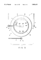
- FIG. 3 is a plan view showing a main part of the cleaning apparatus shown in FIG. 2;
- FIG. 4 is a diagram showing the nozzles and control section of the cleaning apparatus shown in FIG. 2;
- FIGS. 5A to 5D are views showing a cleaning method of the present invention in its order
- FIGS. 6A to 6C are views showing evaluation results of cleaned states in an example of the present invention and comparative examples
- FIG. 7 is a view showing a water mark distribution
- FIGS. 8A to 8C are views explaining Marangoni effect
- FIGS. 9A and 9B are side and plan views, respectively, schematically showing a main part of a modification of the cleaning apparatus
- FIGS. 10A and 10B are side and plan views, respectively, schematically showing a main part of another modification of the cleaning apparatus
- FIG. 11 is a side view schematically showing a main part of still another modification of the cleaning apparatus.
- FIGS. 12A to 12D are views showing a conventional cleaning method in its order.
- FIGS. 13A and 13B are views showing examples of the surface structure of a wafer to be cleaned.
- FIG. 1 is a plan view schematically showing a cleaning system which is provided with a cleaning apparatus according to an embodiment of the present invention.
- the cleaning system has an in/out port 21 to and from which cassettes each containing, e.g., 25 wafers W are transferred from and to the outside.
- a transfer arm 22 movable in X, Y and ⁇ directions and a main arm 23 movable in X, Y, ⁇ and Z, i.e., vertical, directions are arranged.
- a backside cleaning section 25, a finishing section 26, an APM treatment section 27, an HPM treatment section 28, and a hydrofluoric acid treatment section 29 are arranged along a transfer path 24 of the main arm 23.
- a wafer W is processed in the following order.
- the backside of the wafer W is cleaned by, e.g., pure water in the backside cleaning section 25.
- the wafer W is treated with an APM solution (mixture of ammonia, hydrogen peroxide, and pure water) in the APM treatment section 27, so that particles on the wafer W are removed.
- the wafer W is treated with an HPM solution (mixture of hydrochloric acid, hydrogen peroxide, and pure water) in the HPM treatment section 28, so that metallic contaminants on the wafer W are removed.
- the wafer W is treated with a hydrofluoric acid solution in the hydrofluoric acid treatment section 29, so that natural oxide films on the wafer W are removed.
- the wafer W is washed with pure water and is dried in the finishing section 26.
- FIGS. 2 and 3 are partially sectional side view and plan view, respectively, of a main part of the cleaning apparatus, i.e., hydrofluoric acid treatment section 29.
- the cleaning apparatus 29 has an airtight processing chamber 2 which is adjustable to a reduced atmosphere.
- a spin chuck 3 for holding and rotating the wafer W in a horizontal plane is arranged in the processing chamber 2.
- the spin chuck 3 has a rotation plate 33 fixed to the top of a rotation shaft 32 which is rotated about a vertical axis by a rotation mechanism 31 including a motor or the like.
- a mount ring 34 is arranged along the edge of the rotation plate 33 so as to support the edge of the wafer W such that the wafer W is placed above the rotation plate 33 with a gap therebetween. As shown in FIG. 3, part of the mount ring 34 is cut out, so that the wafer W is transferred between the main arm 23 and the mount ring 34.
- Clamp fingers 38a and 38b are arranged along the mount ring 34 at six portions. Each of the clamp fingers 38a and 38b are movable between a clamp position where it engages with the side or edge of the wafer W to fix the wafer W, and a retreat position where it is retreated under the supporting level of the mount ring 34.
- the three clamp fingers 38a constitute one group for cooperating and fixing the wafer W, while the other three clamp fingers 38b constitute another group for cooperating and fixing the wafer W.
- the clamp fingers 38a are driven by a driver 39a supported by the rotation plate 33 while the clamp fingers 38b are driven by a driver 39b supported by the rotation plate 33. As described later, the clamp fingers 38a and clamp fingers 38b are switched from one group to the other during a spin drying operation of the wafer W.
- a double cup structure including an inner cup 4 and an outer cup 5 surrounds the spin chuck 3.
- the double cup structure is moved in a vertical direction by an elevator 35.
- the inner and outer cups 4 and 5 are used for receiving and draining a liquid scattered by rotation of the wafer W.
- the outer cup 5 has a receiving opening 51 located above a receiving opening 41 of the inner cup 4.
- a common gas exhausting path 36 is arranged under the inner and outer cups 4 and 5 so as to exhaust gas in the cups 4 and 5.
- Drain pipes 42 and 52 independent of each other are connected to the inner and outer cups 4 and 5, respectively, at their bottoms.
- Another receiving cup 37 is arranged inside the inner cup 4 to surround the lower part of the spin chuck 3. Liquid stored in the receiving cup 37 is removed through the drain pipe 42 of the inner cup 4. With this double cup structure, a chemical liquid and a rinsing liquid can be collected separately.
- the cleaning apparatus 29 has a chemical liquid nozzle 6, a rinsing nozzle 7, and replacing medium nozzle 8.
- the chemical liquid nozzle 6 is used for supplying a hydrofluoric acid solution of, e.g., 0.5%, onto the surface of the wafer W.
- the rinsing nozzle 7 is used for supplying a rinsing liquid, such as pure water, onto the surface of the wafer W.
- the replacing medium nozzle 8 is used for supplying a replacing medium, such as an organic solvent, e.g., isopropyl alcohol (IPA), onto the surface of the wafer W.
- IPA isopropyl alcohol
- the replacing medium prefferably be mixable with the rinsing liquid, to have surface tension a degree lower than that of the rinsing liquid, and to be volatile, e.g., with a vapor pressure of 10 mmHg to 200 mmHg at 20° C.
- a hydrophilic substance such as IPA, acetone, or methanol, can be used as the replacing medium.
- Each of the nozzles 6, 7, and 8 has a proximal portion inserted in a rotation shaft 61, 71, or 81, and a distal portion extending out of the top of the rotation shaft 61, 71, or 81, and bent facing and in close proximity of the center of the wafer W.
- the distal portion of each nozzle 6, 7, or 8 is fixed to an arm 62, 72, or 82 horizontally extending from the rotation shaft 61, 71, or 81.
- the rotation shafts 61, 71, and 81 are arranged vertical, around the double cup structure at intervals in an angular direction.
- Each of the rotation shafts 61, 71, and 81 is rotated around a vertical axis by a rotation mechanism 63, 73, or 83.
- each of the nozzles 6, 7, and 8 is swingable between a supply position where its tip faces a portion near the center of the wafer W, and a retreat position where its distal portion is placed outside the outer cup 5.
- the rinsing nozzle 7 and replacing medium nozzle 8 are placed on their supply positions at a time during a treatment.
- the tip of the nozzle 7 is located a little distant from the center of the wafer W, and extended in a slanted portion so as to supply pure water, onto the center of the wafer W, while the tip of the nozzle 8 is located above the center of the wafer W, as shown in FIG. 4.
- the proximal portions of the nozzles 6, 7, and 8 are connected to hydrofluoric acid, pure water, and IPA sources (not shown), respectively, through valves 64, 74, and 84, respectively, as shown in FIG. 4.
- the cleaning apparatus further has a control section 9.
- the control section 9 controls the rotation mechanisms 63, 73, and 83, and the valves 64, 74, and 84, in accordance with a predetermined program stored in a memory in advance.
- a spin cleaning method in the cleaning apparatus 29 will be described, in a case where pure water and an IPA liquid are used as the rinsing liquid and replacing medium, respectively.
- a wafer W is placed on the mount ring 34 of the spin chuck 3 by the main arm 23 shown in FIG. 1. Then the wafer W is held by the clamp fingers 38a and rotated at, e.g., 300 rpm by the rotation mechanism 31 of the spin chuck 3.
- the nozzle 6 is swung from the retreat position to the supply position where the tip faces the center of the wafer W.
- the valve 64 is opened and a hydrofluoric acid solution 60 of, e.g., 0.5% is supplied from the nozzle 6 onto the surface of the wafer W near its center, as shown in FIG. 5A, so that natural oxide films on the surface of the wafer W are removed.
- the hydrofluoric acid solution 60 is supplied, e.g, at 1000 ml/min for one minute.
- the double cup structure is set such that the receiving opening 41 of the inner cup 4 faces the edge of the wafer W, as shown in FIG. 2. While the exhausting path 36 is exhausted by exhausting means (not shown), the hydrofluoric acid solution spun off the surface of the wafer W is sucked by the inner cup 4 through the receiving opening 41, and is collected through the drain pipe 42.
- the chemical liquid nozzle 6 is retreated, and the rinsing nozzle 7 and replacing medium nozzle 8 are swung to their supply positions where their tips face the center of the wafer W.
- the valve 74 is opened and a rinsing liquid, such as pure water 70 is supplied from the nozzle 7 onto the surface of the wafer W near its center, as shown in FIG. 5B, so that the surface of the wafer is rinsed.
- the pure water 70 is supplied, e.g, at 1000 ml/min for one minute.
- the double cup structure is set such that the receiving opening 51 of the outer cup 5 faces the edge of the wafer W.
- the pure water spun off the surface of the wafer W is sucked by the outer cup 5 through the receiving opening 51, and is collected through the drain pipe 52.
- the valve 74 Before the supply of the pure water 70 is stopped, i.e., the valve 74 is closed, such as two or three seconds before that, the valve 84 is opened and an IPA liquid 80 used as the replacing medium is supplied from the nozzle 8 onto the surface of the wafer W near its center, as shown in FIG. 5C, so that the rinsing liquid is replaced.
- the IPA liquid 80 is supplied, e.g, at 500 ml/min for ten seconds.
- the wafer W is rotated at 300 rpm during the supply of the hydrofluoric acid solution, pure water, and IPA liquid. After the supply of the IPA liquid is stopped, the wafer W is rotated, e.g., at 300 rpm for one second, then at 3000 rpm for four seconds, and then at 5000 rpm for five seconds. By doing so, the IPA liquid is removed, as shown in FIG. 5D.
- These sequential operations are conducted on the basis of a program stored in the control section 9.
- wafer clamping is switched from the clamp fingers 38a to the clamp fingers 38b during a high speed rotation of 3000 rpm to 5000 rpm.
- the pressure of the processing chamber 2 may be reduced to a vacuum, preferably to a vapor pressure of the replacing medium at the temperature of the wafer W (60 mmHg at 30° C. for IPA), after the pure water 70 is replaced by the IPA liquid 80.
- An inactive gas, such as N 2 may be sprayed onto the surface of the wafer W during the spin drying operation. With these auxiliary operations, the replacing medium can be removed for a shorter period of time.
- the IPA liquid is supplied onto the surface of the wafer W after the pure water is supplied, and thus is dissolved in the pure water on the wafer W. Since IPA has a surface tension smaller than that of pure water and easily wets an underlayer, the pure water is completely replaced by the IPA liquid. Then, the replacing IPA liquid is removed by a centrifugal force. By doing so, the pure water is rapidly removed from the surface of the wafer W. As a result, it is possible to prevent water marks from being formed by precipitation of a product produced by a reaction among water, oxygen in the air, and silicon, or by precipitation of silica contained in the pure water. It follows that particles are less generated to result in an increase in yield. It should be noted that IPA essentially contains no impurities. However, even if the IPA liquid contains a very small amount of impurities, the IPA liquid is removed by a centrifugal force so that a possibility of generating water marks is low.
- the pure water and IPA liquid are preferably supplied in a time-overlapping manner.
- supply of the IPA liquid may be started when supply of the pure water is stopped, without any blank period of time therebetween, so that a short cleaning period of time is attained.
- a common nozzle may be used for supplying both the pure water and IPA liquid.
- no blank period of time is set by opening a valve of an IPA path before closing a valve of a pure water path.
- Dry air or N 2 gas may be sprayed onto the surface of the wafer W along with the supply of the IPA liquid or spin drying operation. By doing so, occurrence of water marks is controlled and removal of the IPA liquid is accelerated.
- the following experiment was conducted to confirm a relationship between generation rate of water marks and conditions in replacement and removal of the pure water with the IPA liquid.
- the distance between the tip opening of the replacing medium nozzle 8 and the surface of the wafer W, i.e., the height NH (cm) of nozzle 8, the inner diameter ID (mm) of the nozzle 8, and the flow speed SS (cm/sec) of the IPA liquid were used as parameters. While the IPA liquid was supplied through the nozzle 8, the wafer W was rotated at 80 rpm. During the spin drying operation, the following Drying Condition (DC) 1 was used.
- DC Drying Condition
- Drying Condition 1 after supplying the IPA liquid, rotating the wafer W at 300 rpm for one second, and then at 3000 rpm for nineteen seconds.
- the inner diameter ID of the nozzle 8 As shown in Table 1, where the inner diameter ID of the nozzle was 4 mm, the water mark average was low, as compared to the cases of 2 mm and 3 mm. With the results, it has been found that the inner diameter ID of the nozzle 8 should be set at 4 mm or more.
- the water mark average became low, with a decrease in the height NH of the nozzle 8, such as 4.0 cm, 2.0 cm, and 1.0 cm. Where the height NH of the nozzle 8 was 2.0 cm, the water mark average was much lower than the case of 4.0 cm and having the same inner diameter ID of the nozzle 8. With the results, it has been found that the height NH of the nozzle 8 should be set at 2.0 cm or less.
- the water mark average was zero.
- the flow speed SS of the IPA liquid 80 was too large, the number of water marks was increased. As a result of additional experiments, it has been found that the flow speed SS should be set at 80 cm/sec or less.
- the IPA liquid 80 is supplied onto the pure water 70 which has been supplied on the wafer W in advance. Since pure water and IPA have different surface tensions, a phenomenon of so called Marangoni effect occurs when the IPA liquid 80 is supplied onto the pure water 70. Marangoni effect is an effect in that a liquid of a lower surface tension is attracted by a liquid of a higher surface tension. Namely, when the IPA liquid 80 is supplied onto the pure water 70, the IPA liquid 80, which has a lower surface tension, is attracted by the pure water 70, which has higher surface tension, as shown in FIG. 8B.
- the IPA liquid 80 As the IPA liquid 80 is being supplied on the wafer W, the IPA liquid 80 is attracted by the pure water 70 and spreads in a concentric manner, as shown in FIG. 8C. The attracted IPA liquid is brought into contact with that part of the pure water which lies in patterns on the wafer W, and with water marks which have already been formed. As a result, the IPA liquid 80 is easily dissolved in the pure water 70 overall.
- the IPA liquid 80 can uniformly flow and spread from near the center of the wafer W in a concentric manner, thereby strengthening the Marangoni effect as described above.
- the height NH is larger and the inner diameter ID is smaller, it becomes difficult for the IPA liquid to uniformly spread in a concentric manner and to push out into the pure water 70 with a strong force.
- the IPA liquid 80 flows along with the pure water 70 in a mixed manner or flows on the surface of the pure water 70, thereby weakening the Marangoni effect.
- the IPA liquid 80 moves a short distance from the spray port of the nozzle 8 to the surface of the wafer W, the IPA liquid 80 is brought into contact with oxygen and water in the atmosphere for a shorter period of time, as compared to a case where the height NH of the nozzle 8 is large. As a result, the amount of oxygen and water contained in the IPA liquid 80 causing water marks is decreased.
- the following experiment was conducted to confirm a relationship between the generation rate of water marks and conditions in the spin drying operation.
- the IPA liquid was supplied onto a wafer W rotated at 80 rpm, while a nozzle height NH of 1.0 cm, a nozzle inner diameter ID of 4 mm, and a IPA flow speed SS of 44 cm/min were used, and then the spin drying operation was carried out.
- the following Drying Conditions (DC) 2 to 4 were used in addition to the above mentioned Drying Condition (DC) 1.
- Drying Condition 2 after supplying the IPA liquid, rotating the wafer W at 300 rpm for one second, then at 1000 rpm for four seconds, and then at 3000 rpm for fifteen seconds.
- Drying Condition 3 after supplying the IPA liquid, rotating the wafer W at 300 rpm for one second, then at 2000 rpm for four seconds, and then at 4000 rpm for fifteen seconds.
- Drying Condition 4 after supplying the IPA liquid, rotating the wafer W at 300 rpm for one second, then at 3000 rpm for four seconds, and then at 5000 rpm for fifteen seconds.
- a high speed rotation of the wafer is also effective to prevent water marks from being formed at those portions of the wafer W which correspond to the clamp fingers 38a. Further, wafer clamping may be switched from the clamp fingers 38a to the clamp fingers 38b during the high speed rotation of the wafer W.
- the following experiment was conducted to confirm a relationship between the generation rate of water marks and a supply period of time of the IPA liquid.
- a nozzle height NH of 1.0 cm, a nozzle inner diameter ID of 4 mm, and an IPA flow speed SS of 44 cm/min were used.
- ST (sec) of the IPA liquid With different supply periods of time ST (sec) of the IPA liquid, the IPA liquid was supplied onto a wafer W rotated at 80 rpm, and then the spin drying operation was carried out.
- a spin cleaning method in the cleaning apparatus 29 will be described, in a case where pure water and an IPA vapor are used as the rinsing liquid and replacing medium, respectively.
- the chemical liquid nozzle 6 is placed on its supply position, and natural oxide films on the surface of a wafer W are removed with a hydrofluoric acid solution 60, as shown in FIG. 5A.
- the hydrofluoric acid solution spun off the surface of the wafer W is sucked by the inner cup 4 through the receiving opening 41, and is collected through the drain pipe 42.
- the chemical liquid nozzle 6 is retreated, and the rinsing nozzle 7 and replacing medium nozzle 8 are swung to their supply positions where their tips face the center of the wafer W.
- the valve 74 is opened and a rinsing liquid, such as pure water 70 is supplied from the nozzle 7 onto the surface of the wafer W near its center, as shown in FIG. 5B, so that the surface of the wafer is rinsed.
- the pure water 70 is supplied, e.g, at 1000 ml/min for one minute.
- the pure water spun off the surface of the wafer W is sucked by the outer cup 5 through the receiving opening 51, and is collected through the drain pipe 52.
- the valve 74 Before the supply of the pure water 70 is stopped, i.e., the valve 74 is closed, such as two or three seconds before that, the valve 84 is opened and an IPA vapor 80 used as the replacing medium is supplied from the nozzle 8 onto the surface of the wafer W near its center, as shown in FIG. 5C, so that the rinsing liquid is replaced.
- the IPA vapor 80 is supplied, e.g, at 1000 ml/min for ten seconds.
- the pure water 70 and IPA vapor 80 are supplied, it is preferable to satisfy a temperature condition, i.e, "room temperature ⁇ temperature of the pure water ⁇ temperature of the IPA vapor".
- a temperature condition i.e, "room temperature ⁇ temperature of the pure water ⁇ temperature of the IPA vapor”.
- the pure water 70 and IPA vapor 80 are supplied at about 30° C. and about 80° C., respectively, where the room temperature is 20° C.
- the temperature of the pure water 70 essentially decides the temperature of the wafer W at the time when the IPA vapor 80 is supplied. By adjusting the temperature condition, it is possible to control condensation and adsorption of the IPA vapor on the surface of the wafer W.
- the wafer W is rotated at 300 rpm during the supply of the hydrofluoric acid solution, pure water, and IPA vapor. After the supply of the IPA vapor is stopped, the wafer W is rotated, e.g., at 300 rpm for one second, then at 3000 rpm for four seconds, and then at 5000 rpm for five seconds. Exhaustion of the process chamber 2 may be increased in synchronism with the rotation being switched to 3000 rpm. By doing so, the IPA vapor is removed, as shown in FIG. 5D.
- wafer clamping is switched from the clamp fingers 38a to the clamp fingers 38b when the rotation is switched from a low speed rotation of 300 rpm to a high speed rotation of 3000 rpm to 5000 rpm, or during the high speed rotation of 3000 rpm to 5000 rpm.
- the pressure of the processing chamber 2 may be reduced to a vacuum, preferably to a vapor pressure of the replacing medium at the temperature of the wafer W (60 mmHg at 30° C. for IPA), after the pure water 70 is replaced by the IPA vapor 80.
- An inactive gas, such as N 2 may be sprayed onto the surface of the wafer W during the spin drying operation. With these auxiliary operations, the replacing medium can be removed for a shorter period of time.
- IPA vapor As the IPA vapor, it is possible to use an IPA vapor having a temperature of about its boiling point, which is obtained by heating an IPA liquid to be saturated. It is also possible to use a mixture of such an IPA vapor and a diluting N 2 , having a temperature of from a room temperature to a boiling point.
- the IPA vapor brought into contact with these surfaces is cooled and part of the vapor beyond its saturation vapor amount is condensed.
- the temperature of the surfaces of the wafer W and pure water is sufficiently high, e.g., higher than the IPA boiling point, the IPA vapor brought into contact with these surfaces is adsorbed on the surfaces.
- the IPA vapor supplied onto the wafer W and dissolved in water on the wafer W demonstrates the Marangoni effect, so that the pure water is replaced with the IPA vapor and removed from the wafer W.
- the temperature of the surface of the wafer W can be controlled by adjusting the temperature of the pure water supplied before the IPA vapor.
- the IPA vapor is obtained by vaporizing an IPA liquid, and removing particles, substances of a high boiling point, metallic contaminants, and the like contained in the IPA liquid, so that purity of the IPA vapor is higher than that of the IPA liquid. In other words, less amount of moisture and impurities are carried over onto the wafer W by the IPA vapor, as compared to an IPA liquid, thereby preventing water marks from being generated.
- FIGS. 9A and 9B are side and plan views, respectively, schematically showing a main part of a modification of the cleaning apparatus, which is improved to allow the IPA vapor to uniformly spread on the wafer W.
- the replacing medium nozzle 8 is designed to move above the wafer W during the supply of the IPA vapor. For example, while the wafer W is rotated at 30 rpm and the IPA vapor is supplied from the nozzle 8, the wafer W is scanned by the nozzle 8 moving outward from the center of the wafer W in a radial direction. By doing so, the IPA vapor can be diffused all over the top surface of the wafer W.
- FIGS. 10A and 10B are side and plan views, respectively, schematically showing a main part of another modification of the cleaning apparatus, which is improved to allow the IPA vapor to uniformly spread on the wafer W.
- the rotation shafts 71 and 81 of the rinsing nozzle 7 and replacing medium nozzle 8 are arranged one on either side of the wafer.
- the nozzles 7 and 8 are moved outward from the center of the wafer W to scan it, with the nozzle 7 going ahead of the nozzle 8, so that the pure water and IPA vapor are essentially simultaneously supplied. By doing so, the pure water supplied on the wafer W is immediately removed by the IPA vapor, thereby effectively preventing water marks from being generated.
- the rotation of the wafer W may be stopped while the replacing medium nozzle 8 scans in the cleaning apparatuses shown in FIGS. 9A to 10B.
- FIG. 11 is a side view schematically showing a main part of still another modification of the cleaning apparatus, which is improved to allow the IPA vapor to uniformly spread on the wafer W.
- a circular rectifying plate 92 is attached to the distal portion of the replacing medium nozzle 8.
- the rectifying plate 92 has a diameter essentially the same as that of the wafer W, and arranged to be centered with the wafer W.
- the distance between the wafer W and rectifying plate 92 is set at about 5 mm.
Abstract
At first, a semiconductor wafer is held and rotated by a spin chuck, and supplied with a hydrofluoric acid solution from a chemical liquid nozzle to remove natural oxide films on the wafer. Then, the wafer is supplied with pure water for rinsing it from a rinsing nozzle while the wafer is rotated. Right before the pure water stops being supplied, the wafer is supplied with an IPA liquid from a replacing medium nozzle while the wafer is rotated. The pure water is replaced with the IPA liquid by means of the Marangoni effect and a centrifugal force. Then, the wafer is rotated at 300 rpm for one second, at 3000 rpm for four seconds, and at 5000 rpm for five seconds, in this order, to remove the IPA liquid by means of a centrifugal force.
Description
1. Field of the Invention
The present invention relates to a spin cleaning method of cleaning a substrate to be treated, such as a semiconductor wafer or an LCD substrate.
2. Description of the Related Art
A process for manufacturing a semiconductor device or a liquid crystal display device (LCD) generally includes a step of cleaning a substrate to be treated, such as a semiconductor wafer or an LCD substrate. The cleaning step is intended to remove particles adhered to the surface of the substrate and a natural oxide film which has been formed by exposing the substrate to the atmosphere. As an apparatus for carrying out the cleaning step, there are a batch type in which a lot of substrates are treated in a process chamber at the same time and a singular type in which substrates are treated in a process chamber one by one. A cleaning apparatus of the singular type generally. utilizes a spin cleaning method.
In the spin cleaning method, a substrate to be treated is held and rotated by a spin chuck. The surface of the substrate is supplied with a chemical liquid and then with pure water used as a rinsing liquid, and is sequentially subjected to a spin drying operation. In addition to make the pure water spun off by a centrifugal force, an inactive gas or clean air may be sprayed onto the surface of the substrate to facilitate the spin drying operation, when the substrate is dried.
A trace of the rinsing liquid, so called "water mark", left on the substrate when dried, is used to evaluate a cleaning state of the substrate. FIGS. 12A to 12D are views schematically showing a manner of a water mark being formed on the surface of, e.g, a semiconductor wafer W, when the surface of the wafer is treated with hydrofluoric acid. At first, as shown in FIG. 12A, a hydrofluoric acid solution 15 is supplied onto the surface of the wafer W while the wafer W is held and rotated by a chuck 11. Then, as shown in FIG. 12B, pure water 16 is supplied from a nozzle 13 to rinse the surface of the wafer W while the pure water is spun off by a centrifugal force. During this step, part of the pure water is left on the surface of the wafer, as shown in FIG. 12C. As a result, a water mark 14 is formed to correspond to the left part of the pure water 16, as shown in FIG. 12D.
It is thought that the water mark is generated as follows. That is, a very small amount of silica (SiO2) is originally contained in the pure water. Further, H2 SiO3 is produced by reaction among water, oxygen in air, and silicon of the wafer, as shown in reaction formula (1).
Si+H.sub.2 O+O.sub.2 →H.sub.2 SiO.sub.3 ( 1)
As a result, a very small amount of SiO2 and H2 SiO3 is contained in the pure water used as the rinsing liquid. On the other hand, while the pure water is being dried on the surface of the wafer, the pure water is divided into a plurality of portions and contracted due to its surface tension. The impurities, SiO2 and H2 SiO3, contained in the pure water are gathered with the pure water being dried, and precipitated as particles on the surface of the wafer, thereby forming water marks.
Especially in the hydrofluoric acid treatment, SiO2 on the surface of the wafer W is removed and Si is exposed, so that the reaction as shown in the reaction formula (1) easily occurs. Further, where a hydrophobic film 18, such as polysilicon, is deposited and a recess 19 is formed on the surface of the wafer W, hardly any of the pure water is spun off so that water marks are apt to be left.
As described above, water marks are formed of impurity particles. With a decrease in the line width of a semiconductor device, a more strict administration is required in relation to particle contamination. As a result, it has been deemed necessary to prevent water marks from being formed.
Jpn. Pat. Appln. KOKAI Publication No. 5-243205 discloses a method of removing a liquid from a substrate surface in a centrifugal machine. In this method, an organic solvent vapor is supplied onto the substrate, which is held by a spin chuck with a vacuum force and is preferably non-rotated, so that the liquid on the substrate is contracted by means of the Marangoni effect. Then the substrate is rotated so that the liquid is removed from the substrate. The organic solvent vapor is supplied in a non-saturated state and at a temperature lower than that of the substrate, so that the organic solvent is prevented from being condensed on the substrate.
In this method, however, it is necessary to make improvements in terms of temperature administration of the organic solvent vapor and safety. Further, there is a problem in that the organic solvent vapor is hardly diffused in a uniform state. Still further, where a so-called spin chuck of the mechanical type, in which a wafer is fixed to the chuck by clamp fingers, is used, water marks are possibly formed at the portions engaged with the clamp fingers.
Therefore, an object of the present invention is to provide a spin cleaning method in which the rate of generating water marks is low.
According to a first aspect of the present invention, there is provided a spin cleaning method comprising:
a rinsing step of supplying a rinsing liquid onto a surface of a substrate to be treated while rotating the substrate;
a replacing step of supplying a replacing medium liquid onto a substantial center of the surface of the substrate from above, and replacing the rinsing liquid with the replacing medium liquid on the surface of the substrate, the replacing medium liquid being mixable with the rinsing liquid and having a degree of surface tension lower than that of the rinsing liquid; and
a removing step of removing the replacing liquid on the surface of the substrate by a centrifugal force which is generated by rotating the substrate.
According to a second aspect of the present invention, there is provided a spin cleaning method comprising:
a rinsing step of supplying a rinsing liquid onto a surface of a substrate to be treated while rotating the substrate;
a replacing step of supplying a replacing medium vapor onto a substantial center of the surface of the substrate from above, and replacing the rinsing liquid with the replacing medium vapor on the surface of the substrate, the replacing medium vapor being mixable with the rinsing liquid and having a degree of surface tension lower than that of the rinsing liquid; and
a removing step of removing the replacing liquid on the surface of the substrate by a centrifugal force which is generated by rotating the substrate,
wherein the rinsing liquid has a temperature higher than 20° C., and the replacing medium vapor has a temperature higher than that of the rinsing liquid, when the rinsing liquid and replacing medium are supplied.
Additional objects and advantages of the invention will be set forth in the description which follows, and in part will be obvious from the description, or may be learned by practice of the invention. The objects and advantages of the invention may be realized and obtained by means of the instrumentalities and combinations particularly pointed out in the appended claims.
The accompanying drawings, which are incorporated in and constitute a part of the specification, illustrate presently preferred embodiments of the invention and, together with the general description given above and the detailed description of the preferred embodiments given below, serve to explain the principles of the invention.
FIG. 1 is a plan view schematically showing a cleaning system;
FIG. 2 is a partially sectional side view of a main part of a cleaning apparatus according to an embodiment of the present invention;
FIG. 3 is a plan view showing a main part of the cleaning apparatus shown in FIG. 2;
FIG. 4 is a diagram showing the nozzles and control section of the cleaning apparatus shown in FIG. 2;
FIGS. 5A to 5D are views showing a cleaning method of the present invention in its order;
FIGS. 6A to 6C are views showing evaluation results of cleaned states in an example of the present invention and comparative examples;
FIG. 7 is a view showing a water mark distribution;
FIGS. 8A to 8C are views explaining Marangoni effect;
FIGS. 9A and 9B are side and plan views, respectively, schematically showing a main part of a modification of the cleaning apparatus;
FIGS. 10A and 10B are side and plan views, respectively, schematically showing a main part of another modification of the cleaning apparatus;
FIG. 11 is a side view schematically showing a main part of still another modification of the cleaning apparatus;
FIGS. 12A to 12D are views showing a conventional cleaning method in its order; and
FIGS. 13A and 13B are views showing examples of the surface structure of a wafer to be cleaned.
FIG. 1 is a plan view schematically showing a cleaning system which is provided with a cleaning apparatus according to an embodiment of the present invention.
The cleaning system has an in/out port 21 to and from which cassettes each containing, e.g., 25 wafers W are transferred from and to the outside. In order to transfer the wafers W, a transfer arm 22 movable in X, Y and θ directions and a main arm 23 movable in X, Y, θ and Z, i.e., vertical, directions are arranged. A backside cleaning section 25, a finishing section 26, an APM treatment section 27, an HPM treatment section 28, and a hydrofluoric acid treatment section 29 are arranged along a transfer path 24 of the main arm 23.
The wafers contained in the cassettes C transferred into the in/out port 21 are taken out by the transfer arm 22, and then received by the main arm 23 and transferred to the treatment sections 25 to 29. For example, a wafer W is processed in the following order.
At first, the backside of the wafer W is cleaned by, e.g., pure water in the backside cleaning section 25. Then, the wafer W is treated with an APM solution (mixture of ammonia, hydrogen peroxide, and pure water) in the APM treatment section 27, so that particles on the wafer W are removed. Then, the wafer W is treated with an HPM solution (mixture of hydrochloric acid, hydrogen peroxide, and pure water) in the HPM treatment section 28, so that metallic contaminants on the wafer W are removed. Then, the wafer W is treated with a hydrofluoric acid solution in the hydrofluoric acid treatment section 29, so that natural oxide films on the wafer W are removed. At last, the wafer W is washed with pure water and is dried in the finishing section 26.
In the APM treatment section 27, HPM treatment section 28, hydrofluoric acid treatment section 29, and the finishing section 26, the wafer W is subjected to a rinsing treatment, and rinsing liquid removal. The structure of a cleaning apparatus according to this embodiment of the present invention is applied to any one of these treatment sections 27, 28, and 29. However, the cleaning apparatus according to this embodiment will be exemplified by the hydrofluoric acid treatment section 29, in which the advantages of the present invention become prominent. FIGS. 2 and 3 are partially sectional side view and plan view, respectively, of a main part of the cleaning apparatus, i.e., hydrofluoric acid treatment section 29.
The cleaning apparatus 29 has an airtight processing chamber 2 which is adjustable to a reduced atmosphere. A spin chuck 3 for holding and rotating the wafer W in a horizontal plane is arranged in the processing chamber 2. The spin chuck 3 has a rotation plate 33 fixed to the top of a rotation shaft 32 which is rotated about a vertical axis by a rotation mechanism 31 including a motor or the like. A mount ring 34 is arranged along the edge of the rotation plate 33 so as to support the edge of the wafer W such that the wafer W is placed above the rotation plate 33 with a gap therebetween. As shown in FIG. 3, part of the mount ring 34 is cut out, so that the wafer W is transferred between the main arm 23 and the mount ring 34.
A double cup structure including an inner cup 4 and an outer cup 5 surrounds the spin chuck 3. The double cup structure is moved in a vertical direction by an elevator 35. The inner and outer cups 4 and 5 are used for receiving and draining a liquid scattered by rotation of the wafer W. The outer cup 5 has a receiving opening 51 located above a receiving opening 41 of the inner cup 4.
A common gas exhausting path 36 is arranged under the inner and outer cups 4 and 5 so as to exhaust gas in the cups 4 and 5. Drain pipes 42 and 52 independent of each other are connected to the inner and outer cups 4 and 5, respectively, at their bottoms. Another receiving cup 37 is arranged inside the inner cup 4 to surround the lower part of the spin chuck 3. Liquid stored in the receiving cup 37 is removed through the drain pipe 42 of the inner cup 4. With this double cup structure, a chemical liquid and a rinsing liquid can be collected separately.
The cleaning apparatus 29 has a chemical liquid nozzle 6, a rinsing nozzle 7, and replacing medium nozzle 8. The chemical liquid nozzle 6 is used for supplying a hydrofluoric acid solution of, e.g., 0.5%, onto the surface of the wafer W. The rinsing nozzle 7 is used for supplying a rinsing liquid, such as pure water, onto the surface of the wafer W. The replacing medium nozzle 8 is used for supplying a replacing medium, such as an organic solvent, e.g., isopropyl alcohol (IPA), onto the surface of the wafer W.
It is preferable for the replacing medium to be mixable with the rinsing liquid, to have surface tension a degree lower than that of the rinsing liquid, and to be volatile, e.g., with a vapor pressure of 10 mmHg to 200 mmHg at 20° C. Where the rinsing liquid consists essentially of pure water or has properties similar to pure water, a hydrophilic substance, such as IPA, acetone, or methanol, can be used as the replacing medium.
Each of the nozzles 6, 7, and 8 has a proximal portion inserted in a rotation shaft 61, 71, or 81, and a distal portion extending out of the top of the rotation shaft 61, 71, or 81, and bent facing and in close proximity of the center of the wafer W. The distal portion of each nozzle 6, 7, or 8 is fixed to an arm 62, 72, or 82 horizontally extending from the rotation shaft 61, 71, or 81. The rotation shafts 61, 71, and 81 are arranged vertical, around the double cup structure at intervals in an angular direction.
Each of the rotation shafts 61, 71, and 81 is rotated around a vertical axis by a rotation mechanism 63, 73, or 83. By this rotation, each of the nozzles 6, 7, and 8 is swingable between a supply position where its tip faces a portion near the center of the wafer W, and a retreat position where its distal portion is placed outside the outer cup 5. The rinsing nozzle 7 and replacing medium nozzle 8 are placed on their supply positions at a time during a treatment. For this reason, upon being placed on the supply positions, the tip of the nozzle 7 is located a little distant from the center of the wafer W, and extended in a slanted portion so as to supply pure water, onto the center of the wafer W, while the tip of the nozzle 8 is located above the center of the wafer W, as shown in FIG. 4.
The proximal portions of the nozzles 6, 7, and 8 are connected to hydrofluoric acid, pure water, and IPA sources (not shown), respectively, through valves 64, 74, and 84, respectively, as shown in FIG. 4. The cleaning apparatus further has a control section 9. The control section 9 controls the rotation mechanisms 63, 73, and 83, and the valves 64, 74, and 84, in accordance with a predetermined program stored in a memory in advance.
A spin cleaning method in the cleaning apparatus 29 will be described, in a case where pure water and an IPA liquid are used as the rinsing liquid and replacing medium, respectively.
At first, a wafer W is placed on the mount ring 34 of the spin chuck 3 by the main arm 23 shown in FIG. 1. Then the wafer W is held by the clamp fingers 38a and rotated at, e.g., 300 rpm by the rotation mechanism 31 of the spin chuck 3.
The nozzle 6 is swung from the retreat position to the supply position where the tip faces the center of the wafer W. The valve 64 is opened and a hydrofluoric acid solution 60 of, e.g., 0.5% is supplied from the nozzle 6 onto the surface of the wafer W near its center, as shown in FIG. 5A, so that natural oxide films on the surface of the wafer W are removed. The hydrofluoric acid solution 60 is supplied, e.g, at 1000 ml/min for one minute.
During this operation, the double cup structure is set such that the receiving opening 41 of the inner cup 4 faces the edge of the wafer W, as shown in FIG. 2. While the exhausting path 36 is exhausted by exhausting means (not shown), the hydrofluoric acid solution spun off the surface of the wafer W is sucked by the inner cup 4 through the receiving opening 41, and is collected through the drain pipe 42.
Then, the chemical liquid nozzle 6 is retreated, and the rinsing nozzle 7 and replacing medium nozzle 8 are swung to their supply positions where their tips face the center of the wafer W. The valve 74 is opened and a rinsing liquid, such as pure water 70 is supplied from the nozzle 7 onto the surface of the wafer W near its center, as shown in FIG. 5B, so that the surface of the wafer is rinsed. The pure water 70 is supplied, e.g, at 1000 ml/min for one minute.
During this operation, the double cup structure is set such that the receiving opening 51 of the outer cup 5 faces the edge of the wafer W. The pure water spun off the surface of the wafer W is sucked by the outer cup 5 through the receiving opening 51, and is collected through the drain pipe 52.
Before the supply of the pure water 70 is stopped, i.e., the valve 74 is closed, such as two or three seconds before that, the valve 84 is opened and an IPA liquid 80 used as the replacing medium is supplied from the nozzle 8 onto the surface of the wafer W near its center, as shown in FIG. 5C, so that the rinsing liquid is replaced. The IPA liquid 80 is supplied, e.g, at 500 ml/min for ten seconds.
The wafer W is rotated at 300 rpm during the supply of the hydrofluoric acid solution, pure water, and IPA liquid. After the supply of the IPA liquid is stopped, the wafer W is rotated, e.g., at 300 rpm for one second, then at 3000 rpm for four seconds, and then at 5000 rpm for five seconds. By doing so, the IPA liquid is removed, as shown in FIG. 5D. These sequential operations are conducted on the basis of a program stored in the control section 9.
It is preferable that wafer clamping is switched from the clamp fingers 38a to the clamp fingers 38b during a high speed rotation of 3000 rpm to 5000 rpm. With this operation, fluids are removed at those portions of the wafer W which correspond to the clamp fingers 38a and water marks are hardly formed there. The pressure of the processing chamber 2 may be reduced to a vacuum, preferably to a vapor pressure of the replacing medium at the temperature of the wafer W (60 mmHg at 30° C. for IPA), after the pure water 70 is replaced by the IPA liquid 80. An inactive gas, such as N2, may be sprayed onto the surface of the wafer W during the spin drying operation. With these auxiliary operations, the replacing medium can be removed for a shorter period of time.
In the cleaning method described above, the IPA liquid is supplied onto the surface of the wafer W after the pure water is supplied, and thus is dissolved in the pure water on the wafer W. Since IPA has a surface tension smaller than that of pure water and easily wets an underlayer, the pure water is completely replaced by the IPA liquid. Then, the replacing IPA liquid is removed by a centrifugal force. By doing so, the pure water is rapidly removed from the surface of the wafer W. As a result, it is possible to prevent water marks from being formed by precipitation of a product produced by a reaction among water, oxygen in the air, and silicon, or by precipitation of silica contained in the pure water. It follows that particles are less generated to result in an increase in yield. It should be noted that IPA essentially contains no impurities. However, even if the IPA liquid contains a very small amount of impurities, the IPA liquid is removed by a centrifugal force so that a possibility of generating water marks is low.
Where a certain period of time is set between the time of stopping the supply of the pure water and the time of starting the supply of the IPA liquid, water drops are formed to increase the generation rate of water marks. For this reason, the pure water and IPA liquid are preferably supplied in a time-overlapping manner. However, supply of the IPA liquid may be started when supply of the pure water is stopped, without any blank period of time therebetween, so that a short cleaning period of time is attained.
A common nozzle may be used for supplying both the pure water and IPA liquid. In this case, no blank period of time is set by opening a valve of an IPA path before closing a valve of a pure water path.
Dry air or N2 gas may be sprayed onto the surface of the wafer W along with the supply of the IPA liquid or spin drying operation. By doing so, occurrence of water marks is controlled and removal of the IPA liquid is accelerated.
Under the conditions (flow rates, supply times, wafer rotation speeds, and the like) set out with reference to FIGS. 5A to 5D, the hydrofluoric acid solution, pure water, and IPA liquid were supplied in this order to clean a wafer W, and then the spin drying operation was carried out. As a result, as shown in FIG. 6A, no water marks were observed on the surface of the wafer W. In order to evaluate generation of watermarks, square areas each having a size of 1 cm by 1 cm were selected on a wafer of 6 inches, as shown in FIG. 6A, and observed by eyes through a microscope of 150 magnifications, so as to count the number of water marks.
As comparative examples, the same evaluations were carried out, in a case where no IPA was supplied in the above described method, and also in a case where N2 gas was sprayed, in place of the IPA liquid, onto the wafer W to accelerate removal of the pure water, in the above described method. The results of the comparative examples are shown in FIGS. 6B and 6C. Where the N2 was sprayed (FIG. 6C), water marks were observed to some extent, though the number of the water marks were reduced, as compared to the case of no N2 being used (FIG. 6A). In contrast, in the method according to the present invention (FIG. 6A), no water marks were observed. With these results, it has been found that the method according to the present invention is effective to prevent water marks from being generated.
The following experiment was conducted to confirm a relationship between generation rate of water marks and conditions in replacement and removal of the pure water with the IPA liquid. In this experiment, the distance between the tip opening of the replacing medium nozzle 8 and the surface of the wafer W, i.e., the height NH (cm) of nozzle 8, the inner diameter ID (mm) of the nozzle 8, and the flow speed SS (cm/sec) of the IPA liquid were used as parameters. While the IPA liquid was supplied through the nozzle 8, the wafer W was rotated at 80 rpm. During the spin drying operation, the following Drying Condition (DC) 1 was used.
Drying Condition 1: after supplying the IPA liquid, rotating the wafer W at 300 rpm for one second, and then at 3000 rpm for nineteen seconds.
Results of the experiment are shown in Table 1. In Table 1, water mark average (WMA) is defined by summing up the number of water marks in areas of water mark distribution (WM distribution) shown in FIG. 7, and then dividing the sum by the number of the areas. Symbols "A", "B", "C", and "D" shown in the column of evaluation EV stand for WMA values of "0", "2.5 or less", "5 or less", and "more than 5", respectively.
As shown in Table 1, where the inner diameter ID of the nozzle was 4 mm, the water mark average was low, as compared to the cases of 2 mm and 3 mm. With the results, it has been found that the inner diameter ID of the nozzle 8 should be set at 4 mm or more.
The water mark average became low, with a decrease in the height NH of the nozzle 8, such as 4.0 cm, 2.0 cm, and 1.0 cm. Where the height NH of the nozzle 8 was 2.0 cm, the water mark average was much lower than the case of 4.0 cm and having the same inner diameter ID of the nozzle 8. With the results, it has been found that the height NH of the nozzle 8 should be set at 2.0 cm or less.
Especially, in the cases where the height NH of the nozzle 8 was set at 2.0 cm or less, and the inner diameter ID of the nozzle 8 was set at 4 mm, the water mark average was zero. With the results, it has been found that the height NH and inner diameter ID of the nozzle 8 should be set at 2.0 cm or less, and at 4 mm or more.
Further, where the flow speed SS of the IPA liquid 80 was too large, the number of water marks was increased. As a result of additional experiments, it has been found that the flow speed SS should be set at 80 cm/sec or less.
              TABLE 1
______________________________________
NH     ID        SS
(cm)   (mm)      (cm/sec) DC      WMA   EV
______________________________________
4.0    4         44       1       1.8   B
4.0    4         78       1       2.2   B
4.0    3         75       1       5.3   D
4.0    2         72       1       6.5   D
2.0    4         44       1       0     A
2.0    4         78       1       0     A
2.0    3         44       1       3.7   C
2.0    2         46       1       4.5   C
1.0    4         44       1       0     A
1.0    4         78       1       0     A
1.0    3         44       1       3.2   C
1.0    2         46       1       4.1   C
1.0    4         117      1       1.3   B
______________________________________
It is thought that water marks are prevented from being generated under the conditions described above on the following basis.
As shown in FIG. 8A, the IPA liquid 80 is supplied onto the pure water 70 which has been supplied on the wafer W in advance. Since pure water and IPA have different surface tensions, a phenomenon of so called Marangoni effect occurs when the IPA liquid 80 is supplied onto the pure water 70. Marangoni effect is an effect in that a liquid of a lower surface tension is attracted by a liquid of a higher surface tension. Namely, when the IPA liquid 80 is supplied onto the pure water 70, the IPA liquid 80, which has a lower surface tension, is attracted by the pure water 70, which has higher surface tension, as shown in FIG. 8B.
As the IPA liquid 80 is being supplied on the wafer W, the IPA liquid 80 is attracted by the pure water 70 and spreads in a concentric manner, as shown in FIG. 8C. The attracted IPA liquid is brought into contact with that part of the pure water which lies in patterns on the wafer W, and with water marks which have already been formed. As a result, the IPA liquid 80 is easily dissolved in the pure water 70 overall.
Where the height NH of the nozzle 8 is as small as 2.0 cm or less, and the inner diameter ID thereof is as large as 4 mm or more, the IPA liquid 80 can uniformly flow and spread from near the center of the wafer W in a concentric manner, thereby strengthening the Marangoni effect as described above. In contrast, if the height NH is larger and the inner diameter ID is smaller, it becomes difficult for the IPA liquid to uniformly spread in a concentric manner and to push out into the pure water 70 with a strong force. As a result, the IPA liquid 80 flows along with the pure water 70 in a mixed manner or flows on the surface of the pure water 70, thereby weakening the Marangoni effect.
Where the height NH of the nozzle 8 is small, there is an effect as follows. That is, the IPA liquid 80 moves a short distance from the spray port of the nozzle 8 to the surface of the wafer W, the IPA liquid 80 is brought into contact with oxygen and water in the atmosphere for a shorter period of time, as compared to a case where the height NH of the nozzle 8 is large. As a result, the amount of oxygen and water contained in the IPA liquid 80 causing water marks is decreased.
The following experiment was conducted to confirm a relationship between the generation rate of water marks and conditions in the spin drying operation. In this experiment, the IPA liquid was supplied onto a wafer W rotated at 80 rpm, while a nozzle height NH of 1.0 cm, a nozzle inner diameter ID of 4 mm, and a IPA flow speed SS of 44 cm/min were used, and then the spin drying operation was carried out. As a state in the spin drying operation, the following Drying Conditions (DC) 2 to 4 were used in addition to the above mentioned Drying Condition (DC) 1.
Drying Condition 2: after supplying the IPA liquid, rotating the wafer W at 300 rpm for one second, then at 1000 rpm for four seconds, and then at 3000 rpm for fifteen seconds.
Drying Condition 3: after supplying the IPA liquid, rotating the wafer W at 300 rpm for one second, then at 2000 rpm for four seconds, and then at 4000 rpm for fifteen seconds.
Drying Condition 4: after supplying the IPA liquid, rotating the wafer W at 300 rpm for one second, then at 3000 rpm for four seconds, and then at 5000 rpm for fifteen seconds.
Results of the experiment are shown in Table 2. As shown in Table 2, no water marks were observed in DCs 1, 3 and 4 except DC 2. On the other hand, where the wafer was rotated at 1000 rpm or more from the beginning just after the IPA liquid supply, the number of particles was increased due to splash back from the cup structure. With the results, it has been found that, after the IPA liquid supply, the wafer W should be rotated at a first rotation speed of 1000 rpm or less, and then at a second rotation speed of 2000 rpm or more, in order to prevent particles and water marks from being generated.
Where the wafer W is rotated at a high speed during the spin drying operation, removal of the IPA liquid is accelerated by a centrifugal force, and the wafer W is rapidly dried. As a result, the reaction shown in the above described reaction formula (1) hardly proceeds, so that less reaction product is produced. In addition the IPA liquid on the wafer is brought into contact with moisture in the atmosphere only for a short period of time, the moisture is not taken into the IPA liquid so much. It is thought that generation rate of water marks is lowered with these reasons.
As described above, where the rotation speed is too high at the beginning of the spin drying operation just after the IPA liquid supply, the pure water and IPA liquid scattered by a centrifugal force are splashed back onto the wafer W, and the number of adhered particles is increased. For this reason, it is preferable to initially rotate the wafer W at the first rotation speed to make big drops spun off, then at the second rotation speed to make small drops spun off.
A high speed rotation of the wafer is also effective to prevent water marks from being formed at those portions of the wafer W which correspond to the clamp fingers 38a. Further, wafer clamping may be switched from the clamp fingers 38a to the clamp fingers 38b during the high speed rotation of the wafer W.
The following experiment was conducted to confirm a relationship between the generation rate of water marks and a supply period of time of the IPA liquid. In this experiment, a nozzle height NH of 1.0 cm, a nozzle inner diameter ID of 4 mm, and an IPA flow speed SS of 44 cm/min were used. With different supply periods of time ST (sec) of the IPA liquid, the IPA liquid was supplied onto a wafer W rotated at 80 rpm, and then the spin drying operation was carried out.
Results of the experiment are shown in Table 3. As shown in Table 3, no water marks were observed where the supply period of time ST was 3 seconds or more, while water marks were observed in the case of ST=2 (sec). With the results, it has been found that the supply period of time ST should be set at 3 sec or more, where the nozzle height NH is 1.0 cm, and the nozzle inner diameter ID is 4 mm or more. It is thought that if the supply period of time ST is too short, the IPA liquid cannot spread out in a concentric manner, thereby lowering replacement of the pure water with the IPA liquid by means of the Marangoni effect.
              TABLE 2
______________________________________
NH     ID        SS
(cm)   (mm)      (cm/sec) DC      WMA   EV
______________________________________
1.0    4         44       1       0     A
1.0    4         44       2       1.1   B
1.0    4         44       3       0     A
1.0    4         44       4       0     A
______________________________________
              TABLE 3
______________________________________
ST      NH     ID       SS
(sec)   (cm)   (mm)     (cm/sec)
                               DC    WMA   EV
______________________________________
10      1.0    4        44     1     0     A
5       1.0    4        44     1     0     A
3       1.0    4        44     1     0     A
2       1.0    4        44     1     2.4   B
______________________________________
A spin cleaning method in the cleaning apparatus 29 will be described, in a case where pure water and an IPA vapor are used as the rinsing liquid and replacing medium, respectively.
At first, the chemical liquid nozzle 6 is placed on its supply position, and natural oxide films on the surface of a wafer W are removed with a hydrofluoric acid solution 60, as shown in FIG. 5A. The hydrofluoric acid solution spun off the surface of the wafer W is sucked by the inner cup 4 through the receiving opening 41, and is collected through the drain pipe 42.
Then, the chemical liquid nozzle 6 is retreated, and the rinsing nozzle 7 and replacing medium nozzle 8 are swung to their supply positions where their tips face the center of the wafer W. The valve 74 is opened and a rinsing liquid, such as pure water 70 is supplied from the nozzle 7 onto the surface of the wafer W near its center, as shown in FIG. 5B, so that the surface of the wafer is rinsed. The pure water 70 is supplied, e.g, at 1000 ml/min for one minute. The pure water spun off the surface of the wafer W is sucked by the outer cup 5 through the receiving opening 51, and is collected through the drain pipe 52.
Before the supply of the pure water 70 is stopped, i.e., the valve 74 is closed, such as two or three seconds before that, the valve 84 is opened and an IPA vapor 80 used as the replacing medium is supplied from the nozzle 8 onto the surface of the wafer W near its center, as shown in FIG. 5C, so that the rinsing liquid is replaced. The IPA vapor 80 is supplied, e.g, at 1000 ml/min for ten seconds.
When the pure water 70 and IPA vapor 80 are supplied, it is preferable to satisfy a temperature condition, i.e, "room temperature≦temperature of the pure water≦temperature of the IPA vapor". For example, the pure water 70 and IPA vapor 80 are supplied at about 30° C. and about 80° C., respectively, where the room temperature is 20° C. The temperature of the pure water 70 essentially decides the temperature of the wafer W at the time when the IPA vapor 80 is supplied. By adjusting the temperature condition, it is possible to control condensation and adsorption of the IPA vapor on the surface of the wafer W.
The wafer W is rotated at 300 rpm during the supply of the hydrofluoric acid solution, pure water, and IPA vapor. After the supply of the IPA vapor is stopped, the wafer W is rotated, e.g., at 300 rpm for one second, then at 3000 rpm for four seconds, and then at 5000 rpm for five seconds. Exhaustion of the process chamber 2 may be increased in synchronism with the rotation being switched to 3000 rpm. By doing so, the IPA vapor is removed, as shown in FIG. 5D. These sequential operations are conducted on the basis of a program stored in the control section 9.
It is preferable that wafer clamping is switched from the clamp fingers 38a to the clamp fingers 38b when the rotation is switched from a low speed rotation of 300 rpm to a high speed rotation of 3000 rpm to 5000 rpm, or during the high speed rotation of 3000 rpm to 5000 rpm. With this operation, water marks are hardly formed at those portions of the wafer W which correspond to the clamp fingers 38a. The pressure of the processing chamber 2 may be reduced to a vacuum, preferably to a vapor pressure of the replacing medium at the temperature of the wafer W (60 mmHg at 30° C. for IPA), after the pure water 70 is replaced by the IPA vapor 80. An inactive gas, such as N2 may be sprayed onto the surface of the wafer W during the spin drying operation. With these auxiliary operations, the replacing medium can be removed for a shorter period of time.
As the IPA vapor, it is possible to use an IPA vapor having a temperature of about its boiling point, which is obtained by heating an IPA liquid to be saturated. It is also possible to use a mixture of such an IPA vapor and a diluting N2, having a temperature of from a room temperature to a boiling point.
Where the temperature of the surfaces of the wafer W and pure water is sufficiently low, the IPA vapor brought into contact with these surfaces is cooled and part of the vapor beyond its saturation vapor amount is condensed. On the other hand, where the temperature of the surfaces of the wafer W and pure water is sufficiently high, e.g., higher than the IPA boiling point, the IPA vapor brought into contact with these surfaces is adsorbed on the surfaces. In this state, the IPA vapor supplied onto the wafer W and dissolved in water on the wafer W demonstrates the Marangoni effect, so that the pure water is replaced with the IPA vapor and removed from the wafer W. The temperature of the surface of the wafer W can be controlled by adjusting the temperature of the pure water supplied before the IPA vapor.
The IPA vapor is obtained by vaporizing an IPA liquid, and removing particles, substances of a high boiling point, metallic contaminants, and the like contained in the IPA liquid, so that purity of the IPA vapor is higher than that of the IPA liquid. In other words, less amount of moisture and impurities are carried over onto the wafer W by the IPA vapor, as compared to an IPA liquid, thereby preventing water marks from being generated.
Where an IPA vapor is used, it is important to allow the vapor to uniformly spread on the wafer W. FIGS. 9A and 9B are side and plan views, respectively, schematically showing a main part of a modification of the cleaning apparatus, which is improved to allow the IPA vapor to uniformly spread on the wafer W.
In the cleaning apparatus shown in FIGS. 9A and 9B, the replacing medium nozzle 8 is designed to move above the wafer W during the supply of the IPA vapor. For example, while the wafer W is rotated at 30 rpm and the IPA vapor is supplied from the nozzle 8, the wafer W is scanned by the nozzle 8 moving outward from the center of the wafer W in a radial direction. By doing so, the IPA vapor can be diffused all over the top surface of the wafer W.
FIGS. 10A and 10B are side and plan views, respectively, schematically showing a main part of another modification of the cleaning apparatus, which is improved to allow the IPA vapor to uniformly spread on the wafer W.
In the cleaning apparatus shown in FIGS. 10A and 10B, the rotation shafts 71 and 81 of the rinsing nozzle 7 and replacing medium nozzle 8 are arranged one on either side of the wafer. The nozzles 7 and 8 are moved outward from the center of the wafer W to scan it, with the nozzle 7 going ahead of the nozzle 8, so that the pure water and IPA vapor are essentially simultaneously supplied. By doing so, the pure water supplied on the wafer W is immediately removed by the IPA vapor, thereby effectively preventing water marks from being generated.
The rotation of the wafer W may be stopped while the replacing medium nozzle 8 scans in the cleaning apparatuses shown in FIGS. 9A to 10B.
FIG. 11 is a side view schematically showing a main part of still another modification of the cleaning apparatus, which is improved to allow the IPA vapor to uniformly spread on the wafer W.
In the cleaning apparatus shown in FIG. 11, a circular rectifying plate 92 is attached to the distal portion of the replacing medium nozzle 8. The rectifying plate 92 has a diameter essentially the same as that of the wafer W, and arranged to be centered with the wafer W. The distance between the wafer W and rectifying plate 92 is set at about 5 mm. With this arrangement, the IPA vapor spreads along the rectifying plate 92, so that the IPA vapor is diffused all over the wafer W up to its edge. In addition, the wafer W is rotated during the supply of the IPA vapor, the IPA vapor is more uniformly diffused on the wafer.
Additional advantages and modifications will readily occur to those skilled in the art. Therefore, the invention in its broader aspects is not limited to the specific details, and illustrated examples shown and described herein. Accordingly, various modifications may be made without departing from the spirit or scope of the general inventive concept as defined by the appended claims and their equivalents.
Claims (23)
1. A spin cleaning method comprising:
an attaching step of attaching a target substrate having a surface to a rotatable spin chuck having a plurality of first clamp fingers to engage with a side of the substrate and fix the substrate;
a chemical liquid treatment step of supplying a chemical liquid onto the surface of the substrate while rotating the substrate, after the attaching step;
a rinsing step of supplying a rinsing liquid onto the surface of the substrate while rotating the substrate, after the chemical liquid treatment step;
a replacing step of supplying a replacing medium liquid onto a substantial center of the surface of the substrate from above, and replacing the rinsing liquid with the replacing medium liquid on the surface of the substrate, the replacing medium liquid being mixable with the rinsing liquid and having a degree of surface tension lower than that of the rinsing liquid, supply of the replacing medium liquid being started before supply of the rinsing liquid is stopped, the substrate being rotated during the replacing step; and
a removing step of removing the replacing liquid on the surface of the substrate by a centrifugal force which is generated by rotating the substrate.
2. The spin cleaning method according to claim 1, further comprising a chemical liquid treatment step of supplying a chemical liquid onto the surface of the substrate while rotating the substrate, before the rinsing step.
3. The spin cleaning method according to claim 1, wherein the replacing medium liquid has a vapor pressure of 10 mmHg to 200 mmHg at 20° C.
4. The spin cleaning method according to claim 1, wherein supply of the replacing liquid is started before supply of the rinsing liquid is stopped.
5. The spin cleaning method according to claim 1, wherein the substrate is rotated during the replacing step.
6. The spin cleaning method according to claim 1, wherein the substrate is held and rotated by a spin chuck, which has a plurality of first clamp fingers to engage with a side of the substrate and fix the substrate.
7. The spin cleaning method according to claim 6, wherein the substrate is rotated first at a first rotation speed of 1000 rpm or less and then at a second rotation speed of 2000 rpm or more in the removing step.
8. The spin cleaning method according to claim 7, wherein the spin chuck has a plurality of second clamp fingers to engage with a side of the substrate and fix the substrate, the substrate being fixed first by the first clamp fingers and then by the second clamp fingers in the removing step.
9. The spin cleaning method according to claim 1, wherein the replacing medium liquid is supplied onto the surface of the substrate from a supply port having an inner diameter of 4 mm or more.
10. The spin cleaning method according to claim 1, wherein the replacing medium liquid is supplied at a flow speed of 80 cm/sec or less.
11. The spin cleaning method according to claim 1, wherein N2 gas is sprayed onto the surface of the substrate in the removing step.
12. A spin cleaning method comprising:
an attaching step of attaching a target substrate having a surface to a rotatable spin chuck having a plurality of first clamp fingers to engage with a side of the substrate and fix the substrate;
a chemical liquid treatment step of supplying a chemical liquid onto the surface of the substrate while rotating the substrate, after the attaching step;
a rinsing step of supplying a rinsing liquid onto the surface of the substrate while rotating the substrate, after the chemical liquid treatment step;
a replacing step of supplying a replacing medium vapor onto a substantial center of the surface of the substrate from above and under such conditions as to substantially maintain the replacing medium vapor in a vapor state, and replacing the rinsing liquid with the replacing medium vapor on the surface of the substrate, the replacing medium vapor being mixable with the rinsing liquid and having a degree of surface tension lower than that of the rinsing liquid, supply of the replacing medium vapor being started before supply of the rinsing liquid is stopped and while the substrate is being rotated, the substrate being rotated during the replacing step, the replacing medium vapor being supplied from a supply port which is moved above the substrate and scans the substrate radially outward from the substantial center of the surface in the replacing step; and
a removing step of removing the replacing liquid on the surface of the substrate by a centrifugal force which is generated by rotating the substrate.
13. The spin cleaning method according to claim 12, further comprising a chemical liquid treatment step of supplying a chemical liquid onto the surface of the substrate while rotating the substrate, before the rinsing step.
14. The spin cleaning method according to claim 12, wherein the replacing medium vapor has a vapor pressure of 10 mmHg to 200 mmHg at 20° C.
15. The spin cleaning method according to. claim 12, wherein supply of the replacing liquid is started before supply of the rinsing liquid is stopped.
16. The spin cleaning method according to claim 12, wherein the substrate is rotated during the replacing step.
17. The spin cleaning method according to claim 12, wherein the substrate is held and rotated by a spin chuck, which has a plurality of first clamp fingers to engage with a side of the substrate and fix the substrate.
18. The spin cleaning method according to claim 17, wherein the substrate is rotated first at a first rotation speed of 1000 rpm or less and then at a second rotation speed of 2000 rpm or more in the removing step.
19. The spin cleaning method according to claim 18, wherein the spin chuck has a plurality of second clamp fingers to engage with a side of the substrate and fix the substrate, the substrate being fixed first by the first clamp fingers and then by the second clamp fingers in the removing step.
20. The spin cleaning method according to claim 12, wherein the replacing medium vapor is supplied from a supply port which is moved above the substrate and scan the substrate in the replacing step.
21. The spin cleaning method according to claim 12, wherein the rinsing liquid and replacing medium vapor are supplied from supply ports which are substantially simultaneously moved above the substrate and scan the substrate in the replacing step, while the supply port of the rinsing liquid goes ahead of the supply port of the replacing medium vapor, so that the rinsing and replacing steps are performed substantially in parallel with each other.
22. The spin cleaning method according to claim 12, wherein the replacing medium is diffused along a rectifying plate, which is placed to face the substrate substantially all over the substrate with a small gap therebetween, during the replacing step.
23. The spin cleaning method according to claim 12, wherein N2 gas is sprayed onto the surface of the substrate in the removing step.
Applications Claiming Priority (2)
| Application Number | Priority Date | Filing Date | Title |
|---|---|---|---|
| JP7-148061 | 1995-05-23 | ||
| JP14806195 | 1995-05-23 |
Publications (1)
| Publication Number | Publication Date |
|---|---|
| US5882433A true US5882433A (en) | 1999-03-16 |
Family
ID=15444319
Family Applications (1)
| Application Number | Title | Priority Date | Filing Date |
|---|---|---|---|
| US08/650,998 Expired - Lifetime US5882433A (en) | 1995-05-23 | 1996-05-21 | Spin cleaning method |
Country Status (3)
| Country | Link |
|---|---|
| US (1) | US5882433A (en) |
| KR (1) | KR100220028B1 (en) |
| TW (1) | TW386235B (en) |
Cited By (181)
| Publication number | Priority date | Publication date | Assignee | Title |
|---|---|---|---|---|
| US5964958A (en) * | 1995-06-07 | 1999-10-12 | Gary W. Ferrell | Methods for drying and cleaning objects using aerosols |
| US5968285A (en) * | 1995-06-07 | 1999-10-19 | Gary W. Ferrell | Methods for drying and cleaning of objects using aerosols and inert gases |
| US6132521A (en) * | 1999-12-20 | 2000-10-17 | Chartered Semiconductor Manufacturing Ltd. | Cleaning metal surfaces with alkyldione peroxides |
| DE19923385A1 (en) * | 1999-05-21 | 2000-11-30 | Wacker Siltronic Halbleitermat | Centrifuge for semiconductor disc, has apparatus which generates layer-like gas flow provided in casing which separates centrifugation process area and semiconductor disc from peripheral outer air |
| WO2000079572A1 (en) * | 1999-06-18 | 2000-12-28 | Lam Research Corporation | Post-plasma processing wafer cleaning method and system |
| US6173720B1 (en) * | 1998-12-02 | 2001-01-16 | International Business Machines Corporation | Process for treating a semiconductor substrate |
| US6174817B1 (en) * | 1998-08-26 | 2001-01-16 | Texas Instruments Incorporated | Two step oxide removal for memory cells |
| US6264752B1 (en) | 1998-03-13 | 2001-07-24 | Gary L. Curtis | Reactor for processing a microelectronic workpiece |
| US6286524B1 (en) * | 1998-02-27 | 2001-09-11 | Kabushiki Kaisha Toshiba | Wafer drying apparatus and method with residual particle removability enhancement |
| EP1136592A2 (en) * | 2000-03-22 | 2001-09-26 | Applied Materials, Inc. | Method and apparatus for removal of unwanted electroplating deposits |
| US6318385B1 (en) | 1998-03-13 | 2001-11-20 | Semitool, Inc. | Micro-environment chamber and system for rinsing and drying a semiconductor workpiece |
| US20010050060A1 (en) * | 1998-03-13 | 2001-12-13 | Semitool, Inc. | System for processing a workpiece |
| US6336463B1 (en) * | 1998-03-31 | 2002-01-08 | Nec Corporation | Cleaning/drying station and production line for semiconductor devices |
| US20020007844A1 (en) * | 2000-07-24 | 2002-01-24 | Takehiko Orii | Cleaning processing method and cleaning processing apparatus |
| WO2002035598A1 (en) * | 2000-10-25 | 2002-05-02 | Infineon Technologies Ag | Method and device for cleaning a semiconductor wafer |
| US6385863B1 (en) * | 1999-06-04 | 2002-05-14 | Sez Semiconductor-Equipment Zubenor Fur Die Habbleiterfertigung | Process and device for drying disk-like objects |
| US20020064963A1 (en) * | 2000-10-10 | 2002-05-30 | Hideto Gotoh | Cleaning agent and cleaning method |
| US20020062840A1 (en) * | 2000-06-26 | 2002-05-30 | Steven Verhaverbeke | Assisted rinsing in a single wafer cleaning process |
| US6413436B1 (en) | 1999-01-27 | 2002-07-02 | Semitool, Inc. | Selective treatment of the surface of a microelectronic workpiece |
| US6423642B1 (en) | 1998-03-13 | 2002-07-23 | Semitool, Inc. | Reactor for processing a semiconductor wafer |
| US6468362B1 (en) | 1999-08-25 | 2002-10-22 | Applied Materials, Inc. | Method and apparatus for cleaning/drying hydrophobic wafers |
| US20020170573A1 (en) * | 2000-05-30 | 2002-11-21 | Christenson Kurt K. | Rinsing processes and equipment |
| US6492284B2 (en) | 1999-01-22 | 2002-12-10 | Semitool, Inc. | Reactor for processing a workpiece using sonic energy |
| US20030000034A1 (en) * | 2001-05-18 | 2003-01-02 | Welsh Christopher M. | Apparatus and method for substrate preparation implementing a surface tension reducing process |
| US6503335B2 (en) | 1998-11-12 | 2003-01-07 | WACKER SILTRONIC GESELLSCHAFT FüR HALBLEITERMATERIALIEN AG | Centrifuge and method for centrifuging a semiconductor wafer |
| US6511914B2 (en) | 1999-01-22 | 2003-01-28 | Semitool, Inc. | Reactor for processing a workpiece using sonic energy |
| US20030020928A1 (en) * | 2000-07-08 | 2003-01-30 | Ritzdorf Thomas L. | Methods and apparatus for processing microelectronic workpieces using metrology |
| US6514352B2 (en) * | 2000-10-10 | 2003-02-04 | Tokyo Electron Limited | Cleaning method using an oxidizing agent, chelating agent and fluorine compound |
| US20030038035A1 (en) * | 2001-05-30 | 2003-02-27 | Wilson Gregory J. | Methods and systems for controlling current in electrochemical processing of microelectronic workpieces |
| US6537416B1 (en) * | 1999-10-01 | 2003-03-25 | Novellus Systems, Inc. | Wafer chuck for use in edge bevel removal of copper from silicon wafers |
| US6543156B2 (en) | 2000-01-12 | 2003-04-08 | Semitool, Inc. | Method and apparatus for high-pressure wafer processing and drying |
| US6548411B2 (en) | 1999-01-22 | 2003-04-15 | Semitool, Inc. | Apparatus and methods for processing a workpiece |
| US20030070918A1 (en) * | 2001-08-31 | 2003-04-17 | Hanson Kyle M. | Apparatus and methods for electrochemical processing of microelectronic workpieces |
| US6555017B1 (en) * | 2000-10-13 | 2003-04-29 | The Regents Of The University Of Caliofornia | Surface contouring by controlled application of processing fluid using Marangoni effect |
| US6572701B2 (en) * | 2001-02-21 | 2003-06-03 | Oki Electric Industry Co., Ltd. | System for separating and recovering waste fluid and spin coater |
| US20030127337A1 (en) * | 1999-04-13 | 2003-07-10 | Hanson Kayle M. | Apparatus and methods for electrochemical processing of microelectronic workpieces |
| US6596082B2 (en) * | 2001-11-30 | 2003-07-22 | Taiwan Semiconductor Manufacturing Co., Ltd | Dual cup spin coating system |
| US20030190426A1 (en) * | 2002-04-03 | 2003-10-09 | Deenesh Padhi | Electroless deposition method |
| US6632292B1 (en) | 1998-03-13 | 2003-10-14 | Semitool, Inc. | Selective treatment of microelectronic workpiece surfaces |
| US6632289B2 (en) | 2000-06-26 | 2003-10-14 | Kabushiki Kaisha Toshiba | Substrate cleaning method and substrate cleaning apparatus |
| US20030192570A1 (en) * | 2002-04-11 | 2003-10-16 | Applied Materials, Inc. | Method and apparatus for wafer cleaning |
| US6642142B2 (en) * | 2001-05-07 | 2003-11-04 | Matsushita Electric Industrial Co., Ltd. | Substrate cleaning method and method for producing an electronic device |
| US20030207206A1 (en) * | 2002-04-22 | 2003-11-06 | General Electric Company | Limited play data storage media and method for limiting access to data thereon |
| US6680253B2 (en) | 1999-01-22 | 2004-01-20 | Semitool, Inc. | Apparatus for processing a workpiece |
| US20040045589A1 (en) * | 1998-09-23 | 2004-03-11 | Imec Vzw | Method and apparatus for removing a liquid from a surface of a substrate |
| US6708701B2 (en) | 2001-10-16 | 2004-03-23 | Applied Materials Inc. | Capillary ring |
| US20040055877A1 (en) * | 1999-04-13 | 2004-03-25 | Wilson Gregory J. | Workpiece processor having processing chamber with improved processing fluid flow |
| US20040060581A1 (en) * | 2002-09-30 | 2004-04-01 | Lam Research Corp. | Vertical proximity processor |
| US20040060580A1 (en) * | 2002-09-30 | 2004-04-01 | Lam Research Corporation | Meniscus, vacuum, IPA vapor, drying manifold |
| US20040060195A1 (en) * | 2002-09-30 | 2004-04-01 | Lam Research Corporation | Methods and systems for processing a substrate using a dynamic Liquid meniscus |
| US20040065540A1 (en) * | 2002-06-28 | 2004-04-08 | Novellus Systems, Inc. | Liquid treatment using thin liquid layer |
| US20040069326A1 (en) * | 2002-09-30 | 2004-04-15 | Lam Research Corporation | Methods and systems for processing a bevel edge of a substrate using a dynamic liquid meniscus |
| US20040069329A1 (en) * | 2000-06-30 | 2004-04-15 | Lam Research Corp. | Method and apparatus for drying semiconductor wafer surfaces using a plurality of inlets and outlets held in close proximity to the wafer surfaces |
| US20040108212A1 (en) * | 2002-12-06 | 2004-06-10 | Lyndon Graham | Apparatus and methods for transferring heat during chemical processing of microelectronic workpieces |
| US6770151B1 (en) | 2001-07-13 | 2004-08-03 | Lam Research Corporation | Drying a substrate using a combination of substrate processing technologies |
| US6786996B2 (en) | 2001-10-16 | 2004-09-07 | Applied Materials Inc. | Apparatus and method for edge bead removal |
| US20040178060A1 (en) * | 2002-09-30 | 2004-09-16 | Lam Research Corp. | Apparatus and method for depositing and planarizing thin films of semiconductor wafers |
| US6796517B1 (en) | 2000-03-09 | 2004-09-28 | Advanced Micro Devices, Inc. | Apparatus for the application of developing solution to a semiconductor wafer |
| US20040194801A1 (en) * | 2003-04-03 | 2004-10-07 | Applied Materials, Inc. | Rotational thermophoretic drying |
| US20040200513A1 (en) * | 2000-09-22 | 2004-10-14 | Dainippon Screen Mfg. Co., Ltd. | Substrate processing apparatus |
| US20040206452A1 (en) * | 2000-09-22 | 2004-10-21 | Dainippon Screen Mfg. Co., Ltd. | Substrate processing apparatus |
| US20040241998A1 (en) * | 1999-01-22 | 2004-12-02 | Hanson Kyle M. | System for processing a workpiece |
| US20050020077A1 (en) * | 2003-04-18 | 2005-01-27 | Applied Materials, Inc. | Formation of protection layer by dripping DI on wafer with high rotation to prevent stain formation from H2O2/H2SO4 chemical splash |
| US20050061676A1 (en) * | 2001-03-12 | 2005-03-24 | Wilson Gregory J. | System for electrochemically processing a workpiece |
| US20050095830A1 (en) * | 2003-10-17 | 2005-05-05 | Applied Materials, Inc. | Selective self-initiating electroless capping of copper with cobalt-containing alloys |
| US20050101130A1 (en) * | 2003-11-07 | 2005-05-12 | Applied Materials, Inc. | Method and tool of chemical doping CoW alloys with Re for increasing barrier properties of electroless capping layers for IC Cu interconnects |
| US20050124158A1 (en) * | 2003-10-15 | 2005-06-09 | Lopatin Sergey D. | Silver under-layers for electroless cobalt alloys |
| US20050124518A1 (en) * | 2001-12-07 | 2005-06-09 | Dainippon Screen Mfg. Co., Ltd. | Substrate treating apparatus |
| US20050136185A1 (en) * | 2002-10-30 | 2005-06-23 | Sivakami Ramanathan | Post rinse to improve selective deposition of electroless cobalt on copper for ULSI application |
| US20050136193A1 (en) * | 2003-10-17 | 2005-06-23 | Applied Materials, Inc. | Selective self-initiating electroless capping of copper with cobalt-containing alloys |
| US20050139318A1 (en) * | 2002-09-30 | 2005-06-30 | Lam Research Corp. | Proximity meniscus manifold |
| US20050148197A1 (en) * | 2002-09-30 | 2005-07-07 | Lam Research Corp. | Substrate proximity processing structures and methods for using and making the same |
| US20050145268A1 (en) * | 2002-09-30 | 2005-07-07 | Lam Research Corp. | Substrate meniscus interface and methods for operation |
| US20050158473A1 (en) * | 2002-09-30 | 2005-07-21 | Lam Research Corp. | Proximity substrate preparation sequence, and method, apparatus, and system for implementing the same |
| US20050155864A1 (en) * | 1999-04-13 | 2005-07-21 | Woodruff Daniel J. | Adaptable electrochemical processing chamber |
| US20050155629A1 (en) * | 2002-09-30 | 2005-07-21 | Lam Research Corp. | Substrate brush scrubbing and proximity cleaning-drying sequence using compatible chemistries, and method, apparatus, and system for implementing the same |
| US20050161320A1 (en) * | 1998-07-10 | 2005-07-28 | Woodruff Daniel J. | Electroplating apparatus with segmented anode array |
| US20050161834A1 (en) * | 2001-09-14 | 2005-07-28 | Cowens Marvin W. | Adhesion by plasma conditioning of semiconductor chip |
| US20050161338A1 (en) * | 2004-01-26 | 2005-07-28 | Applied Materials, Inc. | Electroless cobalt alloy deposition process |
| US20050167274A1 (en) * | 1999-04-13 | 2005-08-04 | Wilson Gregory J. | Tuning electrodes used in a reactor for electrochemically processing a microelectronics workpiece |
| US20050170650A1 (en) * | 2004-01-26 | 2005-08-04 | Hongbin Fang | Electroless palladium nitrate activation prior to cobalt-alloy deposition |
| US20050181226A1 (en) * | 2004-01-26 | 2005-08-18 | Applied Materials, Inc. | Method and apparatus for selectively changing thin film composition during electroless deposition in a single chamber |
| US20050183959A1 (en) * | 2000-04-13 | 2005-08-25 | Wilson Gregory J. | Tuning electrodes used in a reactor for electrochemically processing a microelectric workpiece |
| US20050217707A1 (en) * | 1998-03-13 | 2005-10-06 | Aegerter Brian K | Selective processing of microelectronic workpiece surfaces |
| US20050221621A1 (en) * | 2004-03-31 | 2005-10-06 | Lam Research Corporation | Proximity head heating method and apparatus |
| US20050217703A1 (en) * | 2002-09-30 | 2005-10-06 | Lam Research Corp. | Apparatus and method for utilizing a meniscus in substrate processing |
| US20050217135A1 (en) * | 2002-09-30 | 2005-10-06 | Lam Research Corp. | Phobic barrier meniscus separation and containment |
| US20050227888A1 (en) * | 2000-06-26 | 2005-10-13 | Steven Verhaverbeke | Cleaning method and solution for cleaning a wafer in a single wafer process |
| US6954993B1 (en) | 2002-09-30 | 2005-10-18 | Lam Research Corporation | Concentric proximity processing head |
| US20050253268A1 (en) * | 2004-04-22 | 2005-11-17 | Shao-Ta Hsu | Method and structure for improving adhesion between intermetal dielectric layer and cap layer |
| US20060000716A1 (en) * | 1999-04-13 | 2006-01-05 | Wilson Gregory J | Tuning electrodes used in a reactor for electrochemically processing a microelectronic workpiece |
| US20060033678A1 (en) * | 2004-01-26 | 2006-02-16 | Applied Materials, Inc. | Integrated electroless deposition system |
| US20060054181A1 (en) * | 2000-06-26 | 2006-03-16 | Applied Materials, Inc. | Cleaning method and solution for cleaning a wafer in a single wafer process |
| US20060088982A1 (en) * | 2003-06-24 | 2006-04-27 | Lam Research Corp. | System method and apparatus for dry-in, dry-out, low defect laser dicing using proximity technology |
| WO2006063936A1 (en) * | 2004-12-14 | 2006-06-22 | Sez Ag | Apparatus and method for drying disk-shaped substrates |
| US20060183240A1 (en) * | 2001-12-04 | 2006-08-17 | Hiroki Taniyama | Substrate processing apparatus |
| US20060219258A1 (en) * | 2005-04-01 | 2006-10-05 | Fsi International, Inc. | Methods for rinsing microelectronic substrates utilizing cool rinse fluid within a gas enviroment including a drying enhancement substance |
| US20060240187A1 (en) * | 2005-01-27 | 2006-10-26 | Applied Materials, Inc. | Deposition of an intermediate catalytic layer on a barrier layer for copper metallization |
| US20060246699A1 (en) * | 2005-03-18 | 2006-11-02 | Weidman Timothy W | Process for electroless copper deposition on a ruthenium seed |
| US20060252252A1 (en) * | 2005-03-18 | 2006-11-09 | Zhize Zhu | Electroless deposition processes and compositions for forming interconnects |
| US20060264043A1 (en) * | 2005-03-18 | 2006-11-23 | Stewart Michael P | Electroless deposition process on a silicon contact |
| US20060283485A1 (en) * | 2002-03-12 | 2006-12-21 | Dainippon Screen Mfg. Co., Ltd. | Substrate treating apparatus and substrate treating method |
| US20070012339A1 (en) * | 2005-02-03 | 2007-01-18 | Tokyo Electron Limited | Cleaning apparatus, coating and developing apparatus, and cleaning method |
| US20070017555A1 (en) * | 2005-06-23 | 2007-01-25 | Kenji Sekiguchi | Substrate Processing method and substrate processing apparatus |
| US7170190B1 (en) | 2003-12-16 | 2007-01-30 | Lam Research Corporation | Apparatus for oscillating a head and methods for implementing the same |
| US20070071888A1 (en) * | 2005-09-21 | 2007-03-29 | Arulkumar Shanmugasundram | Method and apparatus for forming device features in an integrated electroless deposition system |
| US20070099422A1 (en) * | 2005-10-28 | 2007-05-03 | Kapila Wijekoon | Process for electroless copper deposition |
| US20070108404A1 (en) * | 2005-10-28 | 2007-05-17 | Stewart Michael P | Method of selectively depositing a thin film material at a semiconductor interface |
| WO2007054377A1 (en) * | 2005-05-13 | 2007-05-18 | Sez Ag | Method for drying a surface |
| US20070131247A1 (en) * | 2005-12-13 | 2007-06-14 | Blalock Guy T | Method and apparatus for surface tension control in advanced photolithography |
| US20070157947A1 (en) * | 2006-01-12 | 2007-07-12 | Deok Ho Kim | Substrate drying apparatus and method of substrate drying using the same |
| US20070199579A1 (en) * | 2006-02-17 | 2007-08-30 | Kei Hayasaki | Substrate treatment method, substrate treatment apparatus, and semiconductor device manufacturing method |
| US20070223342A1 (en) * | 2004-10-12 | 2007-09-27 | Takehiko Orii | Substrate Processing Method and Substrate Processing Apparatus |
| US20070221502A1 (en) * | 1999-04-13 | 2007-09-27 | Semitool, Inc. | Tuning electrodes used in a reactor for electrochemically processing a microelectronic workpiece |
| US20070295365A1 (en) * | 2006-06-27 | 2007-12-27 | Katsuhiko Miya | Substrate processing method and substrate processing apparatus |
| US20080052947A1 (en) * | 2006-08-29 | 2008-03-06 | Katsuhiko Miya | Substrate processing method and substrate processing apparatus |
| US20080078426A1 (en) * | 2006-09-28 | 2008-04-03 | Katsuhiko Miya | Substrate processing apparatus and substrate processing method |
| US20080083883A1 (en) * | 2006-10-06 | 2008-04-10 | Lam Research Corporation | Methods of and apparatus for accessing a process chamber using a dual zone gas injector with improved optical access |
| US20080093340A1 (en) * | 2006-10-06 | 2008-04-24 | Mitsunori Nakamori | Substrate processing method, substrate processing apparatus, and storage medium |
| US7367345B1 (en) | 2002-09-30 | 2008-05-06 | Lam Research Corporation | Apparatus and method for providing a confined liquid for immersion lithography |
| US7383843B2 (en) | 2002-09-30 | 2008-06-10 | Lam Research Corporation | Method and apparatus for processing wafer surfaces using thin, high velocity fluid layer |
| US20080142054A1 (en) * | 2006-12-18 | 2008-06-19 | Atsuro Eitoku | Substrate processing method and substrate processing apparatus |
| US20080152922A1 (en) * | 2006-12-21 | 2008-06-26 | Wing Lau Cheng | Hybrid composite wafer carrier for wet clean equipment |
| US20080190454A1 (en) * | 2007-02-09 | 2008-08-14 | Atsuro Eitoku | Substrate treatment method and substrate treatment apparatus |
| US20080251101A1 (en) * | 2004-04-23 | 2008-10-16 | Hiroki Ohno | Substrate Cleaning Method, Substrate Cleaning Equipment, Computer Program, and Program Recording Medium |
| US20080266367A1 (en) * | 2002-09-30 | 2008-10-30 | Mike Ravkin | Single phase proximity head having a controlled meniscus for treating a substrate |
| US20080314422A1 (en) * | 2007-06-19 | 2008-12-25 | Lam Research Corporation | System, method and apparatus for maintaining separation of liquids in a controlled meniscus |
| US20090032062A1 (en) * | 2007-07-30 | 2009-02-05 | Planar Semiconductor, Inc. | Method for precision cleaning and drying flat objects |
| US20090032068A1 (en) * | 2002-06-13 | 2009-02-05 | Applied Materials, Inc. | Single wafer method and apparatus for drying semiconductor substrates using an inert gas air-knife |
| US20090032067A1 (en) * | 2007-07-30 | 2009-02-05 | Tomonori Kojimaru | Substrate processing apparatus and substrate processing method |
| US20090056766A1 (en) * | 2007-08-29 | 2009-03-05 | Tokyo Electron Limited | Substrate processing apparatus and method |
| US20090071940A1 (en) * | 2007-09-13 | 2009-03-19 | Sokudo Co., Ltd. | Multi-speed substrate processing apparatus and substrate processing method |
| US20090145464A1 (en) * | 2007-03-30 | 2009-06-11 | Lam Research Corporation | Proximity head with angled vacuum conduit system, apparatus and method |
| US7584761B1 (en) | 2000-06-30 | 2009-09-08 | Lam Research Corporation | Wafer edge surface treatment with liquid meniscus |
| US7614411B2 (en) | 2002-09-30 | 2009-11-10 | Lam Research Corporation | Controls of ambient environment during wafer drying using proximity head |
| US7632376B1 (en) | 2002-09-30 | 2009-12-15 | Lam Research Corporation | Method and apparatus for atomic layer deposition (ALD) in a proximity system |
| US7651934B2 (en) | 2005-03-18 | 2010-01-26 | Applied Materials, Inc. | Process for electroless copper deposition |
| US20100055924A1 (en) * | 2008-08-27 | 2010-03-04 | Novellus Systems, Inc. | Apparatus and method for edge bevel removal of copper from silicon wafers |
| US20100206338A1 (en) * | 2006-10-02 | 2010-08-19 | Sez Ag | Device and method for removing liquid from a surface of a disc-like article |
| US7780867B1 (en) * | 1999-10-01 | 2010-08-24 | Novellus Systems, Inc. | Edge bevel removal of copper from silicon wafers |
| US20100219920A1 (en) * | 2009-02-27 | 2010-09-02 | Novellus Systems, Inc. | Magnetically actuated chuck for edge bevel removal |
| US8100081B1 (en) | 2006-06-30 | 2012-01-24 | Novellus Systems, Inc. | Edge removal of films using externally generated plasma species |
| US20120080061A1 (en) * | 2010-10-04 | 2012-04-05 | Samsung Electronics Co., Ltd. | Apparatus For Drying Substrate |
| US20120103371A1 (en) * | 2010-10-28 | 2012-05-03 | Lam Research Ag | Method and apparatus for drying a semiconductor wafer |
| US8464736B1 (en) | 2007-03-30 | 2013-06-18 | Lam Research Corporation | Reclaim chemistry |
| US8486201B2 (en) | 2009-07-16 | 2013-07-16 | Lam Research Ag | Method for drying a semiconductor wafer |
| US8580045B2 (en) | 2009-05-29 | 2013-11-12 | Lam Research Corporation | Method and apparatus for physical confinement of a liquid meniscus over a semiconductor wafer |
| US8691022B1 (en) | 2012-12-18 | 2014-04-08 | Lam Research Ag | Method and apparatus for processing wafer-shaped articles |
| CN103811302A (en) * | 2012-11-08 | 2014-05-21 | 大日本网屏制造株式会社 | Substrate treatment method and substrate treatment apparatus |
| DE102006033492B4 (en) * | 2005-07-20 | 2014-07-03 | Disco Corp. | Semiconductor wafer processing apparatus |
| US8815111B2 (en) | 2010-09-28 | 2014-08-26 | Dainippon Screen Mfg. Co., Ltd. | Substrate treatment method and substrate treatment apparatus |
| TWI460807B (en) * | 2011-05-27 | 2014-11-11 | Lam Res Ag | Method and apparatus for liquid treatment of wafer shaped articles |
| US20140360536A1 (en) * | 2013-06-07 | 2014-12-11 | Tokyo Electron Limited | Substrate processing apparatus, substrate processing method and computer-readable storage medium recording therein substrate processing program |
| US8967935B2 (en) | 2011-07-06 | 2015-03-03 | Tel Nexx, Inc. | Substrate loader and unloader |
| US9028621B2 (en) | 2010-07-07 | 2015-05-12 | Screen Semiconductor Solutions Co., Ltd. | Substrate cleaning method and substrate cleaning device |
| US9093482B2 (en) | 2012-10-12 | 2015-07-28 | Lam Research Ag | Method and apparatus for liquid treatment of wafer shaped articles |
| CN104952699A (en) * | 2014-03-25 | 2015-09-30 | 斯克林集团公司 | Substrate treatment method and substrate treatment apparatus |
| US20160045938A1 (en) * | 2014-08-15 | 2016-02-18 | SCREEN Holdings Co., Ltd. | Substrate treatment apparatus, and substrate treatment method |
| US9316443B2 (en) | 2012-08-23 | 2016-04-19 | Lam Research Ag | Method and apparatus for liquid treatment of wafer shaped articles |
| US9355836B2 (en) | 2013-12-31 | 2016-05-31 | Lam Research Ag | Method and apparatus for liquid treatment of wafer shaped articles |
| US9355883B2 (en) | 2011-09-09 | 2016-05-31 | Lam Research Ag | Method and apparatus for liquid treatment of wafer shaped articles |
| US9421617B2 (en) | 2011-06-22 | 2016-08-23 | Tel Nexx, Inc. | Substrate holder |
| CN106252199A (en) * | 2015-06-10 | 2016-12-21 | 株式会社思可林集团 | Substrate processing method using same and substrate board treatment |
| CN106463377A (en) * | 2014-05-01 | 2017-02-22 | 东京毅力科创株式会社 | Substrate-processing device, substrate-processing method, and computer-readable recording medium on which substrate-processing program has been recorded |
| US20170117163A1 (en) * | 2012-03-28 | 2017-04-27 | SCREEN Holdings Co., Ltd. | Substrate processing apparatus and substrate processing method |
| US9728443B2 (en) | 2014-02-27 | 2017-08-08 | SCREEN Holdings Co., Ltd. | Substrate processing apparatus and substrate processing method |
| US9732416B1 (en) | 2007-04-18 | 2017-08-15 | Novellus Systems, Inc. | Wafer chuck with aerodynamic design for turbulence reduction |
| US9748120B2 (en) | 2013-07-01 | 2017-08-29 | Lam Research Ag | Apparatus for liquid treatment of disc-shaped articles and heating system for use in such apparatus |
| US20180277356A1 (en) * | 2017-03-27 | 2018-09-27 | SCREEN Holdings Co., Ltd. | Substrate processing method and substrate processing apparatus |
| TWI641021B (en) * | 2016-09-12 | 2018-11-11 | 日商斯庫林集團股份有限公司 | Substrate processing method and substrate processing apparatus |
| US10281210B2 (en) | 2013-03-07 | 2019-05-07 | Shibaura Mechatronics Corporation | Substrate processing apparatus and substrate processing method |
| US10347511B2 (en) * | 2012-11-26 | 2019-07-09 | Applied Materials, Inc. | Stiction-free drying process with contaminant removal for high-aspect ratio semiconductor device STR |
| US10406566B2 (en) * | 2013-09-30 | 2019-09-10 | Shibaura Mechatronics Corporation | Substrate processing device and substrate processing method |
| US10410888B2 (en) | 2014-02-27 | 2019-09-10 | Lam Research Ag | Device and method for removing liquid from a surface of a disc-like article |
| US10475670B2 (en) | 2014-03-19 | 2019-11-12 | SCREEN Holdings Co., Ltd. | Substrate processing apparatus and substrate processing method |
| US10510528B2 (en) | 2015-06-16 | 2019-12-17 | SCREEN Holdings Co., Ltd. | Substrate processing method |
| CN111739829A (en) * | 2020-08-26 | 2020-10-02 | 华海清科(北京)科技有限公司 | Wafer drying method and system |
| US10903092B2 (en) | 2016-03-17 | 2021-01-26 | SCREEN Holdings Co., Ltd. | Substrate processing apparatus and substrate processing method |
| US11139183B2 (en) | 2018-05-24 | 2021-10-05 | Taiwan Semiconductor Manufacturing Co., Ltd. | Systems and methods for dry wafer transport |
| US11273464B2 (en) * | 2019-08-07 | 2022-03-15 | Tokyo Electron Limited | Substrate processing apparatus |
| US11728185B2 (en) | 2021-01-05 | 2023-08-15 | Applied Materials, Inc. | Steam-assisted single substrate cleaning process and apparatus |
Families Citing this family (1)
| Publication number | Priority date | Publication date | Assignee | Title |
|---|---|---|---|---|
| JP6979826B2 (en) * | 2017-08-04 | 2021-12-15 | 東京エレクトロン株式会社 | Board processing method and board processing equipment |
Citations (6)
| Publication number | Priority date | Publication date | Assignee | Title |
|---|---|---|---|---|
| JPS62188323A (en) * | 1986-02-14 | 1987-08-17 | Dainippon Screen Mfg Co Ltd | Method and equipment for washing and drying substrate |
| JPH05243205A (en) * | 1990-03-01 | 1993-09-21 | Philips Gloeilampenfab:Nv | Method for removing liquid on substrate surface in centrifugal machine |
| US5271774A (en) * | 1990-03-01 | 1993-12-21 | U.S. Philips Corporation | Method for removing in a centrifuge a liquid from a surface of a substrate |
| JPH06275596A (en) * | 1993-03-19 | 1994-09-30 | Hitachi Ltd | Vapor treatment device |
| US5660642A (en) * | 1995-05-26 | 1997-08-26 | The Regents Of The University Of California | Moving zone Marangoni drying of wet objects using naturally evaporated solvent vapor |
| US5715612A (en) * | 1995-08-17 | 1998-02-10 | Schwenkler; Robert S. | Method for precision drying surfaces |
-
1996
- 1996-05-18 TW TW085105921A patent/TW386235B/en not_active IP Right Cessation
- 1996-05-21 US US08/650,998 patent/US5882433A/en not_active Expired - Lifetime
- 1996-05-22 KR KR1019960017458A patent/KR100220028B1/en not_active IP Right Cessation
Patent Citations (6)
| Publication number | Priority date | Publication date | Assignee | Title |
|---|---|---|---|---|
| JPS62188323A (en) * | 1986-02-14 | 1987-08-17 | Dainippon Screen Mfg Co Ltd | Method and equipment for washing and drying substrate |
| JPH05243205A (en) * | 1990-03-01 | 1993-09-21 | Philips Gloeilampenfab:Nv | Method for removing liquid on substrate surface in centrifugal machine |
| US5271774A (en) * | 1990-03-01 | 1993-12-21 | U.S. Philips Corporation | Method for removing in a centrifuge a liquid from a surface of a substrate |
| JPH06275596A (en) * | 1993-03-19 | 1994-09-30 | Hitachi Ltd | Vapor treatment device |
| US5660642A (en) * | 1995-05-26 | 1997-08-26 | The Regents Of The University Of California | Moving zone Marangoni drying of wet objects using naturally evaporated solvent vapor |
| US5715612A (en) * | 1995-08-17 | 1998-02-10 | Schwenkler; Robert S. | Method for precision drying surfaces |
Cited By (341)
| Publication number | Priority date | Publication date | Assignee | Title |
|---|---|---|---|---|
| US5968285A (en) * | 1995-06-07 | 1999-10-19 | Gary W. Ferrell | Methods for drying and cleaning of objects using aerosols and inert gases |
| US5964958A (en) * | 1995-06-07 | 1999-10-12 | Gary W. Ferrell | Methods for drying and cleaning objects using aerosols |
| US6286524B1 (en) * | 1998-02-27 | 2001-09-11 | Kabushiki Kaisha Toshiba | Wafer drying apparatus and method with residual particle removability enhancement |
| US20040023494A1 (en) * | 1998-03-13 | 2004-02-05 | Semitool, Inc. | Selective treatment of microelectronic workpiece surfaces |
| US6632292B1 (en) | 1998-03-13 | 2003-10-14 | Semitool, Inc. | Selective treatment of microelectronic workpiece surfaces |
| US6558470B2 (en) | 1998-03-13 | 2003-05-06 | Semitool, Inc. | Reactor for processing a microelectronic workpiece |
| US6666922B2 (en) | 1998-03-13 | 2003-12-23 | Semitool, Inc. | System for processing a workpiece |
| US20050217707A1 (en) * | 1998-03-13 | 2005-10-06 | Aegerter Brian K | Selective processing of microelectronic workpiece surfaces |
| US6660098B2 (en) | 1998-03-13 | 2003-12-09 | Semitool, Inc. | System for processing a workpiece |
| US6264752B1 (en) | 1998-03-13 | 2001-07-24 | Gary L. Curtis | Reactor for processing a microelectronic workpiece |
| US6494956B2 (en) | 1998-03-13 | 2002-12-17 | Semitool, Inc. | System for processing a workpiece |
| US6622737B2 (en) * | 1998-03-13 | 2003-09-23 | Semitool, Inc. | Micro-environment chamber and system for rinsing and drying a semiconductor workpiece |
| US6318385B1 (en) | 1998-03-13 | 2001-11-20 | Semitool, Inc. | Micro-environment chamber and system for rinsing and drying a semiconductor workpiece |
| US20010050060A1 (en) * | 1998-03-13 | 2001-12-13 | Semitool, Inc. | System for processing a workpiece |
| US6997988B2 (en) | 1998-03-13 | 2006-02-14 | Semitool, Inc. | System for processing a workpiece |
| US6695914B2 (en) | 1998-03-13 | 2004-02-24 | Semitool, Inc. | System for processing a workpiece |
| US6350319B1 (en) | 1998-03-13 | 2002-02-26 | Semitool, Inc. | Micro-environment reactor for processing a workpiece |
| US6447633B1 (en) | 1998-03-13 | 2002-09-10 | Semitdol, Inc. | Reactor for processing a semiconductor wafer |
| US6446643B2 (en) | 1998-03-13 | 2002-09-10 | Semitool, Inc. | Micro-environment chamber and system for rinsing and drying a semiconductor workpiece |
| US6423642B1 (en) | 1998-03-13 | 2002-07-23 | Semitool, Inc. | Reactor for processing a semiconductor wafer |
| US20050032391A1 (en) * | 1998-03-13 | 2005-02-10 | Semitool, Inc. | Method for processing a semiconductor wafer |
| US20050233589A1 (en) * | 1998-03-13 | 2005-10-20 | Aegerter Brian K | Processes for removing residue from a workpiece |
| US6336463B1 (en) * | 1998-03-31 | 2002-01-08 | Nec Corporation | Cleaning/drying station and production line for semiconductor devices |
| US20050161336A1 (en) * | 1998-07-10 | 2005-07-28 | Woodruff Daniel J. | Electroplating apparatus with segmented anode array |
| US20050161320A1 (en) * | 1998-07-10 | 2005-07-28 | Woodruff Daniel J. | Electroplating apparatus with segmented anode array |
| US6174817B1 (en) * | 1998-08-26 | 2001-01-16 | Texas Instruments Incorporated | Two step oxide removal for memory cells |
| US20040045589A1 (en) * | 1998-09-23 | 2004-03-11 | Imec Vzw | Method and apparatus for removing a liquid from a surface of a substrate |
| US7527698B2 (en) | 1998-09-23 | 2009-05-05 | Interuniversitair Microelektronica Centrum (Imec, Vzw) | Method and apparatus for removing a liquid from a surface of a substrate |
| US6503335B2 (en) | 1998-11-12 | 2003-01-07 | WACKER SILTRONIC GESELLSCHAFT FüR HALBLEITERMATERIALIEN AG | Centrifuge and method for centrifuging a semiconductor wafer |
| US6354309B1 (en) | 1998-12-02 | 2002-03-12 | International Business Machines Corporation | Process for treating a semiconductor substrate |
| US6173720B1 (en) * | 1998-12-02 | 2001-01-16 | International Business Machines Corporation | Process for treating a semiconductor substrate |
| US6511914B2 (en) | 1999-01-22 | 2003-01-28 | Semitool, Inc. | Reactor for processing a workpiece using sonic energy |
| US20020144973A1 (en) * | 1999-01-22 | 2002-10-10 | Semitool, Inc. | Selective treatment of the surface of a microelectronic workpiece |
| US7217325B2 (en) | 1999-01-22 | 2007-05-15 | Semitool, Inc. | System for processing a workpiece |
| US20040241998A1 (en) * | 1999-01-22 | 2004-12-02 | Hanson Kyle M. | System for processing a workpiece |
| US6492284B2 (en) | 1999-01-22 | 2002-12-10 | Semitool, Inc. | Reactor for processing a workpiece using sonic energy |
| US6548411B2 (en) | 1999-01-22 | 2003-04-15 | Semitool, Inc. | Apparatus and methods for processing a workpiece |
| US6680253B2 (en) | 1999-01-22 | 2004-01-20 | Semitool, Inc. | Apparatus for processing a workpiece |
| US6413436B1 (en) | 1999-01-27 | 2002-07-02 | Semitool, Inc. | Selective treatment of the surface of a microelectronic workpiece |
| US20020168863A1 (en) * | 1999-01-27 | 2002-11-14 | Semitool, Inc. | Selective treatment of the surface of a microelectronic workpiece |
| US20050167265A1 (en) * | 1999-04-13 | 2005-08-04 | Wilson Gregory J. | System for electrochemically processing a workpiece |
| US20050205409A1 (en) * | 1999-04-13 | 2005-09-22 | Hanson Kyle M | Apparatus and methods for electrochemical processing of microelectronic workpieces |
| US20050167273A1 (en) * | 1999-04-13 | 2005-08-04 | Wilson Gregory J. | Tuning electrodes used in a reactor for electrochemically processing a microelectronic workpiece |
| US20050109629A1 (en) * | 1999-04-13 | 2005-05-26 | Wilson Gregory J. | System for electrochemically processing a workpiece |
| US20070221502A1 (en) * | 1999-04-13 | 2007-09-27 | Semitool, Inc. | Tuning electrodes used in a reactor for electrochemically processing a microelectronic workpiece |
| US20050155864A1 (en) * | 1999-04-13 | 2005-07-21 | Woodruff Daniel J. | Adaptable electrochemical processing chamber |
| US20050224340A1 (en) * | 1999-04-13 | 2005-10-13 | Wilson Gregory J | System for electrochemically processing a workpiece |
| US20050211551A1 (en) * | 1999-04-13 | 2005-09-29 | Hanson Kyle M | Apparatus and methods for electrochemical processing of microelectronic workpieces |
| US20030127337A1 (en) * | 1999-04-13 | 2003-07-10 | Hanson Kayle M. | Apparatus and methods for electrochemical processing of microelectronic workpieces |
| US20050109628A1 (en) * | 1999-04-13 | 2005-05-26 | Wilson Gregory J. | System for electrochemically processing a workpiece |
| US20050167274A1 (en) * | 1999-04-13 | 2005-08-04 | Wilson Gregory J. | Tuning electrodes used in a reactor for electrochemically processing a microelectronics workpiece |
| US20040055877A1 (en) * | 1999-04-13 | 2004-03-25 | Wilson Gregory J. | Workpiece processor having processing chamber with improved processing fluid flow |
| US20050109625A1 (en) * | 1999-04-13 | 2005-05-26 | Wilson Gregory J. | System for electrochemically processing a workpiece |
| US20050109633A1 (en) * | 1999-04-13 | 2005-05-26 | Wilson Gregory J. | System for electrochemically processing a workpiece |
| US20060000716A1 (en) * | 1999-04-13 | 2006-01-05 | Wilson Gregory J | Tuning electrodes used in a reactor for electrochemically processing a microelectronic workpiece |
| US20050189227A1 (en) * | 1999-04-13 | 2005-09-01 | Wilson Gregory J. | Tuning electrodes used in a reactor for electrochemically processing a microelectronic workpiece |
| DE19923385C2 (en) * | 1999-05-21 | 2001-05-31 | Wacker Siltronic Halbleitermat | Process for drying a semiconductor wafer |
| DE19923385A1 (en) * | 1999-05-21 | 2000-11-30 | Wacker Siltronic Halbleitermat | Centrifuge for semiconductor disc, has apparatus which generates layer-like gas flow provided in casing which separates centrifugation process area and semiconductor disc from peripheral outer air |
| US6385863B1 (en) * | 1999-06-04 | 2002-05-14 | Sez Semiconductor-Equipment Zubenor Fur Die Habbleiterfertigung | Process and device for drying disk-like objects |
| WO2000079572A1 (en) * | 1999-06-18 | 2000-12-28 | Lam Research Corporation | Post-plasma processing wafer cleaning method and system |
| JP2003502859A (en) * | 1999-06-18 | 2003-01-21 | ラム リサーチ コーポレーション | Method and system for cleaning wafer after plasma processing |
| US6468362B1 (en) | 1999-08-25 | 2002-10-22 | Applied Materials, Inc. | Method and apparatus for cleaning/drying hydrophobic wafers |
| US6967174B1 (en) | 1999-10-01 | 2005-11-22 | Novellus Systems, Inc. | Wafer chuck for use in edge bevel removal of copper from silicon wafers |
| US6537416B1 (en) * | 1999-10-01 | 2003-03-25 | Novellus Systems, Inc. | Wafer chuck for use in edge bevel removal of copper from silicon wafers |
| US7780867B1 (en) * | 1999-10-01 | 2010-08-24 | Novellus Systems, Inc. | Edge bevel removal of copper from silicon wafers |
| US6255266B1 (en) * | 1999-12-20 | 2001-07-03 | Chartered Semiconductor Manufacturing Ltd. | Alkyldione peroxides as cleaning solutions for wafer fabs |
| US6132521A (en) * | 1999-12-20 | 2000-10-17 | Chartered Semiconductor Manufacturing Ltd. | Cleaning metal surfaces with alkyldione peroxides |
| US6543156B2 (en) | 2000-01-12 | 2003-04-08 | Semitool, Inc. | Method and apparatus for high-pressure wafer processing and drying |
| US6796517B1 (en) | 2000-03-09 | 2004-09-28 | Advanced Micro Devices, Inc. | Apparatus for the application of developing solution to a semiconductor wafer |
| EP1136592A2 (en) * | 2000-03-22 | 2001-09-26 | Applied Materials, Inc. | Method and apparatus for removal of unwanted electroplating deposits |
| EP1136592A3 (en) * | 2000-03-22 | 2009-03-25 | Applied Materials, Inc. | Method and apparatus for removal of unwanted electroplating deposits |
| US20050183959A1 (en) * | 2000-04-13 | 2005-08-25 | Wilson Gregory J. | Tuning electrodes used in a reactor for electrochemically processing a microelectric workpiece |
| US7364625B2 (en) * | 2000-05-30 | 2008-04-29 | Fsi International, Inc. | Rinsing processes and equipment |
| US20020170573A1 (en) * | 2000-05-30 | 2002-11-21 | Christenson Kurt K. | Rinsing processes and equipment |
| US20060054181A1 (en) * | 2000-06-26 | 2006-03-16 | Applied Materials, Inc. | Cleaning method and solution for cleaning a wafer in a single wafer process |
| US7449127B2 (en) | 2000-06-26 | 2008-11-11 | Applied Materials, Inc. | Cleaning method and solution for cleaning a wafer in a single wafer process |
| US6632289B2 (en) | 2000-06-26 | 2003-10-14 | Kabushiki Kaisha Toshiba | Substrate cleaning method and substrate cleaning apparatus |
| US20040103915A1 (en) * | 2000-06-26 | 2004-06-03 | Steven Verhaverbeke | Assisted rinsing in a single wafer cleaning process |
| US7456113B2 (en) * | 2000-06-26 | 2008-11-25 | Applied Materials, Inc. | Cleaning method and solution for cleaning a wafer in a single wafer process |
| US7021319B2 (en) * | 2000-06-26 | 2006-04-04 | Applied Materials Inc. | Assisted rinsing in a single wafer cleaning process |
| US6945259B2 (en) | 2000-06-26 | 2005-09-20 | Kabushiki Kaisha Toshiba | Substrate cleaning method and substrate cleaning apparatus |
| US7469883B2 (en) | 2000-06-26 | 2008-12-30 | Applied Materials, Inc. | Cleaning method and solution for cleaning a wafer in a single wafer process |
| US20020062840A1 (en) * | 2000-06-26 | 2002-05-30 | Steven Verhaverbeke | Assisted rinsing in a single wafer cleaning process |
| US20050227888A1 (en) * | 2000-06-26 | 2005-10-13 | Steven Verhaverbeke | Cleaning method and solution for cleaning a wafer in a single wafer process |
| US20040000324A1 (en) * | 2000-06-26 | 2004-01-01 | Kabushiki Kaisha Toshiba | Substrate cleaning method and substrate cleaning apparatus |
| US20060264343A1 (en) * | 2000-06-26 | 2006-11-23 | Steven Verhaverbeke | Cleaning method and solution for cleaning a wafer in a single wafer process |
| US20060270242A1 (en) * | 2000-06-26 | 2006-11-30 | Steven Verhaverbeke | Cleaning method and solution for cleaning a wafer in a single wafer process |
| US20040069329A1 (en) * | 2000-06-30 | 2004-04-15 | Lam Research Corp. | Method and apparatus for drying semiconductor wafer surfaces using a plurality of inlets and outlets held in close proximity to the wafer surfaces |
| US7234477B2 (en) | 2000-06-30 | 2007-06-26 | Lam Research Corporation | Method and apparatus for drying semiconductor wafer surfaces using a plurality of inlets and outlets held in close proximity to the wafer surfaces |
| US7584761B1 (en) | 2000-06-30 | 2009-09-08 | Lam Research Corporation | Wafer edge surface treatment with liquid meniscus |
| US20030020928A1 (en) * | 2000-07-08 | 2003-01-30 | Ritzdorf Thomas L. | Methods and apparatus for processing microelectronic workpieces using metrology |
| US6863741B2 (en) * | 2000-07-24 | 2005-03-08 | Tokyo Electron Limited | Cleaning processing method and cleaning processing apparatus |
| US20020007844A1 (en) * | 2000-07-24 | 2002-01-24 | Takehiko Orii | Cleaning processing method and cleaning processing apparatus |
| US7428907B2 (en) * | 2000-09-22 | 2008-09-30 | Dainippon Screen Mfg. Co., Ltd. | Substrate processing apparatus |
| US6951221B2 (en) * | 2000-09-22 | 2005-10-04 | Dainippon Screen Mfg. Co., Ltd. | Substrate processing apparatus |
| US20040200513A1 (en) * | 2000-09-22 | 2004-10-14 | Dainippon Screen Mfg. Co., Ltd. | Substrate processing apparatus |
| US20040206378A1 (en) * | 2000-09-22 | 2004-10-21 | Dainippon Screen Mfg. Co., Ltd. | Substrate processing apparatus |
| US20040206452A1 (en) * | 2000-09-22 | 2004-10-21 | Dainippon Screen Mfg. Co., Ltd. | Substrate processing apparatus |
| US20040206379A1 (en) * | 2000-09-22 | 2004-10-21 | Dainippon Screen Mfg. Co., Ltd. | Substrate processing apparatus |
| US7267130B2 (en) | 2000-09-22 | 2007-09-11 | Dainippon Screen Mfg. Co., Ltd. | Substrate processing apparatus |
| US7479205B2 (en) | 2000-09-22 | 2009-01-20 | Dainippon Screen Mfg. Co., Ltd. | Substrate processing apparatus |
| US6875288B2 (en) | 2000-10-10 | 2005-04-05 | Tokyo Electron Limited | Cleaning agent and cleaning method |
| US6514352B2 (en) * | 2000-10-10 | 2003-02-04 | Tokyo Electron Limited | Cleaning method using an oxidizing agent, chelating agent and fluorine compound |
| US20020064963A1 (en) * | 2000-10-10 | 2002-05-30 | Hideto Gotoh | Cleaning agent and cleaning method |
| US20030141275A1 (en) * | 2000-10-13 | 2003-07-31 | The Regents Of The University Of California | Apparatus for etching or depositing a desired profile onto a surface |
| US6740194B2 (en) * | 2000-10-13 | 2004-05-25 | The Regents Of The University Of California | Apparatus for etching or depositing a desired profile onto a surface |
| US6555017B1 (en) * | 2000-10-13 | 2003-04-29 | The Regents Of The University Of Caliofornia | Surface contouring by controlled application of processing fluid using Marangoni effect |
| US20030186553A1 (en) * | 2000-10-25 | 2003-10-02 | Grit Bonsdorf | Process and device for cleaning a semiconductor wafer |
| US6833324B2 (en) | 2000-10-25 | 2004-12-21 | Infineon Technologies Ag | Process and device for cleaning a semiconductor wafer |
| WO2002035598A1 (en) * | 2000-10-25 | 2002-05-02 | Infineon Technologies Ag | Method and device for cleaning a semiconductor wafer |
| US6572701B2 (en) * | 2001-02-21 | 2003-06-03 | Oki Electric Industry Co., Ltd. | System for separating and recovering waste fluid and spin coater |
| US20050061676A1 (en) * | 2001-03-12 | 2005-03-24 | Wilson Gregory J. | System for electrochemically processing a workpiece |
| US6642142B2 (en) * | 2001-05-07 | 2003-11-04 | Matsushita Electric Industrial Co., Ltd. | Substrate cleaning method and method for producing an electronic device |
| US20030000034A1 (en) * | 2001-05-18 | 2003-01-02 | Welsh Christopher M. | Apparatus and method for substrate preparation implementing a surface tension reducing process |
| US7000623B2 (en) | 2001-05-18 | 2006-02-21 | Lam Research Corporation | Apparatus and method for substrate preparation implementing a surface tension reducing process |
| US20030038035A1 (en) * | 2001-05-30 | 2003-02-27 | Wilson Gregory J. | Methods and systems for controlling current in electrochemical processing of microelectronic workpieces |
| WO2003001576A3 (en) * | 2001-06-25 | 2003-04-03 | Applied Materials Inc | Assisted rinsing in a single wafer cleaning process |
| WO2003001576A2 (en) * | 2001-06-25 | 2003-01-03 | Applied Materials, Inc. | Assisted rinsing in a single wafer cleaning process |
| US6770151B1 (en) | 2001-07-13 | 2004-08-03 | Lam Research Corporation | Drying a substrate using a combination of substrate processing technologies |
| US20030070918A1 (en) * | 2001-08-31 | 2003-04-17 | Hanson Kyle M. | Apparatus and methods for electrochemical processing of microelectronic workpieces |
| US20050161834A1 (en) * | 2001-09-14 | 2005-07-28 | Cowens Marvin W. | Adhesion by plasma conditioning of semiconductor chip |
| US20050212149A1 (en) * | 2001-09-14 | 2005-09-29 | Cowens Marvin W | Adhesion by plasma conditioning of semiconductor chip surfaces |
| US7445960B2 (en) | 2001-09-14 | 2008-11-04 | Texas Instruments Incorporated | Adhesion by plasma conditioning of semiconductor chip |
| US20070128881A1 (en) * | 2001-09-14 | 2007-06-07 | Cowens Marvin W | Adhesion by plasma conditioning of semiconductor chip surfaces |
| US20080050860A1 (en) * | 2001-09-14 | 2008-02-28 | Cowens Marvin W | Adhesion by plasma conditioning of semiconductor chip |
| US7276401B2 (en) | 2001-09-14 | 2007-10-02 | Texas Instruments Incorporated | Adhesion by plasma conditioning of semiconductor chip surfaces |
| US6786996B2 (en) | 2001-10-16 | 2004-09-07 | Applied Materials Inc. | Apparatus and method for edge bead removal |
| US6708701B2 (en) | 2001-10-16 | 2004-03-23 | Applied Materials Inc. | Capillary ring |
| US6596082B2 (en) * | 2001-11-30 | 2003-07-22 | Taiwan Semiconductor Manufacturing Co., Ltd | Dual cup spin coating system |
| US20060183240A1 (en) * | 2001-12-04 | 2006-08-17 | Hiroki Taniyama | Substrate processing apparatus |
| US20050124518A1 (en) * | 2001-12-07 | 2005-06-09 | Dainippon Screen Mfg. Co., Ltd. | Substrate treating apparatus |
| US20060283485A1 (en) * | 2002-03-12 | 2006-12-21 | Dainippon Screen Mfg. Co., Ltd. | Substrate treating apparatus and substrate treating method |
| US20030190426A1 (en) * | 2002-04-03 | 2003-10-09 | Deenesh Padhi | Electroless deposition method |
| US20030192570A1 (en) * | 2002-04-11 | 2003-10-16 | Applied Materials, Inc. | Method and apparatus for wafer cleaning |
| US20090205677A1 (en) * | 2002-04-11 | 2009-08-20 | Randhir Thakur | Method and apparatus for wafer cleaning |
| US20030207206A1 (en) * | 2002-04-22 | 2003-11-06 | General Electric Company | Limited play data storage media and method for limiting access to data thereon |
| US8322045B2 (en) | 2002-06-13 | 2012-12-04 | Applied Materials, Inc. | Single wafer apparatus for drying semiconductor substrates using an inert gas air-knife |
| US20090032068A1 (en) * | 2002-06-13 | 2009-02-05 | Applied Materials, Inc. | Single wafer method and apparatus for drying semiconductor substrates using an inert gas air-knife |
| US20090044839A1 (en) * | 2002-06-13 | 2009-02-19 | Applied Materials, Inc. | Single wafer method and apparatus for drying semiconductor substrates using an inert gas air-knife |
| US20040065540A1 (en) * | 2002-06-28 | 2004-04-08 | Novellus Systems, Inc. | Liquid treatment using thin liquid layer |
| US20080266367A1 (en) * | 2002-09-30 | 2008-10-30 | Mike Ravkin | Single phase proximity head having a controlled meniscus for treating a substrate |
| US7997288B2 (en) | 2002-09-30 | 2011-08-16 | Lam Research Corporation | Single phase proximity head having a controlled meniscus for treating a substrate |
| US7000622B2 (en) | 2002-09-30 | 2006-02-21 | Lam Research Corporation | Methods and systems for processing a bevel edge of a substrate using a dynamic liquid meniscus |
| US7293571B2 (en) | 2002-09-30 | 2007-11-13 | Lam Research Corporation | Substrate proximity processing housing and insert for generating a fluid meniscus |
| US20050217703A1 (en) * | 2002-09-30 | 2005-10-06 | Lam Research Corp. | Apparatus and method for utilizing a meniscus in substrate processing |
| US7632376B1 (en) | 2002-09-30 | 2009-12-15 | Lam Research Corporation | Method and apparatus for atomic layer deposition (ALD) in a proximity system |
| US7264007B2 (en) | 2002-09-30 | 2007-09-04 | Lam Research Corporation | Method and apparatus for cleaning a substrate using megasonic power |
| US7045018B2 (en) | 2002-09-30 | 2006-05-16 | Lam Research Corporation | Substrate brush scrubbing and proximity cleaning-drying sequence using compatible chemistries, and method, apparatus, and system for implementing the same |
| US7367345B1 (en) | 2002-09-30 | 2008-05-06 | Lam Research Corporation | Apparatus and method for providing a confined liquid for immersion lithography |
| US7383843B2 (en) | 2002-09-30 | 2008-06-10 | Lam Research Corporation | Method and apparatus for processing wafer surfaces using thin, high velocity fluid layer |
| US20040060195A1 (en) * | 2002-09-30 | 2004-04-01 | Lam Research Corporation | Methods and systems for processing a substrate using a dynamic Liquid meniscus |
| US7069937B2 (en) | 2002-09-30 | 2006-07-04 | Lam Research Corporation | Vertical proximity processor |
| US20040060573A1 (en) * | 2002-09-30 | 2004-04-01 | Lam Research Corporation | System for substrate processing with meniscus, vacuum, IPA vapor, drying manifold |
| US7093375B2 (en) | 2002-09-30 | 2006-08-22 | Lam Research Corporation | Apparatus and method for utilizing a meniscus in substrate processing |
| US7614411B2 (en) | 2002-09-30 | 2009-11-10 | Lam Research Corporation | Controls of ambient environment during wafer drying using proximity head |
| US20040060580A1 (en) * | 2002-09-30 | 2004-04-01 | Lam Research Corporation | Meniscus, vacuum, IPA vapor, drying manifold |
| US7127831B2 (en) | 2002-09-30 | 2006-10-31 | Lam Research Corporation | Methods and systems for processing a substrate using a dynamic liquid meniscus |
| US7513262B2 (en) | 2002-09-30 | 2009-04-07 | Lam Research Corporation | Substrate meniscus interface and methods for operation |
| US20040069319A1 (en) * | 2002-09-30 | 2004-04-15 | Lam Research Corp. | Method and apparatus for cleaning a substrate using megasonic power |
| US6988327B2 (en) | 2002-09-30 | 2006-01-24 | Lam Research Corporation | Methods and systems for processing a substrate using a dynamic liquid meniscus |
| US20040069326A1 (en) * | 2002-09-30 | 2004-04-15 | Lam Research Corporation | Methods and systems for processing a bevel edge of a substrate using a dynamic liquid meniscus |
| US20040060581A1 (en) * | 2002-09-30 | 2004-04-01 | Lam Research Corp. | Vertical proximity processor |
| US7240679B2 (en) | 2002-09-30 | 2007-07-10 | Lam Research Corporation | System for substrate processing with meniscus, vacuum, IPA vapor, drying manifold |
| US20050217135A1 (en) * | 2002-09-30 | 2005-10-06 | Lam Research Corp. | Phobic barrier meniscus separation and containment |
| US7153400B2 (en) | 2002-09-30 | 2006-12-26 | Lam Research Corporation | Apparatus and method for depositing and planarizing thin films of semiconductor wafers |
| US20040178060A1 (en) * | 2002-09-30 | 2004-09-16 | Lam Research Corp. | Apparatus and method for depositing and planarizing thin films of semiconductor wafers |
| US7389783B2 (en) | 2002-09-30 | 2008-06-24 | Lam Research Corporation | Proximity meniscus manifold |
| US8236382B2 (en) | 2002-09-30 | 2012-08-07 | Lam Research Corporation | Proximity substrate preparation sequence, and method, apparatus, and system for implementing the same |
| US20050155629A1 (en) * | 2002-09-30 | 2005-07-21 | Lam Research Corp. | Substrate brush scrubbing and proximity cleaning-drying sequence using compatible chemistries, and method, apparatus, and system for implementing the same |
| US7198055B2 (en) | 2002-09-30 | 2007-04-03 | Lam Research Corporation | Meniscus, vacuum, IPA vapor, drying manifold |
| US20050158473A1 (en) * | 2002-09-30 | 2005-07-21 | Lam Research Corp. | Proximity substrate preparation sequence, and method, apparatus, and system for implementing the same |
| US20050145268A1 (en) * | 2002-09-30 | 2005-07-07 | Lam Research Corp. | Substrate meniscus interface and methods for operation |
| US20050148197A1 (en) * | 2002-09-30 | 2005-07-07 | Lam Research Corp. | Substrate proximity processing structures and methods for using and making the same |
| US6954993B1 (en) | 2002-09-30 | 2005-10-18 | Lam Research Corporation | Concentric proximity processing head |
| US20050139318A1 (en) * | 2002-09-30 | 2005-06-30 | Lam Research Corp. | Proximity meniscus manifold |
| US20050136185A1 (en) * | 2002-10-30 | 2005-06-23 | Sivakami Ramanathan | Post rinse to improve selective deposition of electroless cobalt on copper for ULSI application |
| US20040108212A1 (en) * | 2002-12-06 | 2004-06-10 | Lyndon Graham | Apparatus and methods for transferring heat during chemical processing of microelectronic workpieces |
| US20040194801A1 (en) * | 2003-04-03 | 2004-10-07 | Applied Materials, Inc. | Rotational thermophoretic drying |
| US20060102198A1 (en) * | 2003-04-03 | 2006-05-18 | Steven Verhaverbeke | Rotational thermophoretic drying |
| US7011715B2 (en) * | 2003-04-03 | 2006-03-14 | Applied Materials, Inc. | Rotational thermophoretic drying |
| US20050020077A1 (en) * | 2003-04-18 | 2005-01-27 | Applied Materials, Inc. | Formation of protection layer by dripping DI on wafer with high rotation to prevent stain formation from H2O2/H2SO4 chemical splash |
| US20060088982A1 (en) * | 2003-06-24 | 2006-04-27 | Lam Research Corp. | System method and apparatus for dry-in, dry-out, low defect laser dicing using proximity technology |
| US7675000B2 (en) | 2003-06-24 | 2010-03-09 | Lam Research Corporation | System method and apparatus for dry-in, dry-out, low defect laser dicing using proximity technology |
| US7064065B2 (en) | 2003-10-15 | 2006-06-20 | Applied Materials, Inc. | Silver under-layers for electroless cobalt alloys |
| US20050124158A1 (en) * | 2003-10-15 | 2005-06-09 | Lopatin Sergey D. | Silver under-layers for electroless cobalt alloys |
| US20050136193A1 (en) * | 2003-10-17 | 2005-06-23 | Applied Materials, Inc. | Selective self-initiating electroless capping of copper with cobalt-containing alloys |
| US20050095830A1 (en) * | 2003-10-17 | 2005-05-05 | Applied Materials, Inc. | Selective self-initiating electroless capping of copper with cobalt-containing alloys |
| US7205233B2 (en) | 2003-11-07 | 2007-04-17 | Applied Materials, Inc. | Method for forming CoWRe alloys by electroless deposition |
| US20050101130A1 (en) * | 2003-11-07 | 2005-05-12 | Applied Materials, Inc. | Method and tool of chemical doping CoW alloys with Re for increasing barrier properties of electroless capping layers for IC Cu interconnects |
| US7170190B1 (en) | 2003-12-16 | 2007-01-30 | Lam Research Corporation | Apparatus for oscillating a head and methods for implementing the same |
| US20050170650A1 (en) * | 2004-01-26 | 2005-08-04 | Hongbin Fang | Electroless palladium nitrate activation prior to cobalt-alloy deposition |
| US20060033678A1 (en) * | 2004-01-26 | 2006-02-16 | Applied Materials, Inc. | Integrated electroless deposition system |
| US20050181226A1 (en) * | 2004-01-26 | 2005-08-18 | Applied Materials, Inc. | Method and apparatus for selectively changing thin film composition during electroless deposition in a single chamber |
| US20050161338A1 (en) * | 2004-01-26 | 2005-07-28 | Applied Materials, Inc. | Electroless cobalt alloy deposition process |
| US20050221621A1 (en) * | 2004-03-31 | 2005-10-06 | Lam Research Corporation | Proximity head heating method and apparatus |
| US8062471B2 (en) | 2004-03-31 | 2011-11-22 | Lam Research Corporation | Proximity head heating method and apparatus |
| US20050253268A1 (en) * | 2004-04-22 | 2005-11-17 | Shao-Ta Hsu | Method and structure for improving adhesion between intermetal dielectric layer and cap layer |
| US7837804B2 (en) * | 2004-04-23 | 2010-11-23 | Tokyo Electron Limited | Substrate cleaning method, substrate cleaning equipment, computer program, and program recording medium |
| US20080251101A1 (en) * | 2004-04-23 | 2008-10-16 | Hiroki Ohno | Substrate Cleaning Method, Substrate Cleaning Equipment, Computer Program, and Program Recording Medium |
| US20070223342A1 (en) * | 2004-10-12 | 2007-09-27 | Takehiko Orii | Substrate Processing Method and Substrate Processing Apparatus |
| US8337659B2 (en) * | 2004-10-12 | 2012-12-25 | Tokyo Electron Limited | Substrate processing method and substrate processing apparatus |
| US8794250B2 (en) | 2004-10-12 | 2014-08-05 | Tokyo Electron Limited | Substrate processing method and substrate processing apparatus |
| WO2006063936A1 (en) * | 2004-12-14 | 2006-06-22 | Sez Ag | Apparatus and method for drying disk-shaped substrates |
| US20080011330A1 (en) * | 2004-12-14 | 2008-01-17 | Sez Ag | Apparatus And Method For Drying Disk-Shaped Substrates |
| US20060240187A1 (en) * | 2005-01-27 | 2006-10-26 | Applied Materials, Inc. | Deposition of an intermediate catalytic layer on a barrier layer for copper metallization |
| US20070012339A1 (en) * | 2005-02-03 | 2007-01-18 | Tokyo Electron Limited | Cleaning apparatus, coating and developing apparatus, and cleaning method |
| US7712475B2 (en) * | 2005-02-03 | 2010-05-11 | Tokyo Electron Limited | Cleaning apparatus, coating and developing apparatus, and cleaning method |
| US20100154834A1 (en) * | 2005-02-03 | 2010-06-24 | Tokyo Electron Limited | Cleaning apparatus, coating and developing apparatus, and cleaning method |
| US8001983B2 (en) | 2005-02-03 | 2011-08-23 | Tokyo Electron Limited | Cleaning apparatus, coating and developing apparatus, and cleaning method |
| US7651934B2 (en) | 2005-03-18 | 2010-01-26 | Applied Materials, Inc. | Process for electroless copper deposition |
| US7659203B2 (en) | 2005-03-18 | 2010-02-09 | Applied Materials, Inc. | Electroless deposition process on a silicon contact |
| US20060252252A1 (en) * | 2005-03-18 | 2006-11-09 | Zhize Zhu | Electroless deposition processes and compositions for forming interconnects |
| US20060264043A1 (en) * | 2005-03-18 | 2006-11-23 | Stewart Michael P | Electroless deposition process on a silicon contact |
| US7514353B2 (en) | 2005-03-18 | 2009-04-07 | Applied Materials, Inc. | Contact metallization scheme using a barrier layer over a silicide layer |
| US20060251800A1 (en) * | 2005-03-18 | 2006-11-09 | Weidman Timothy W | Contact metallization scheme using a barrier layer over a silicide layer |
| US20060246699A1 (en) * | 2005-03-18 | 2006-11-02 | Weidman Timothy W | Process for electroless copper deposition on a ruthenium seed |
| US8070884B2 (en) | 2005-04-01 | 2011-12-06 | Fsi International, Inc. | Methods for rinsing microelectronic substrates utilizing cool rinse fluid within a gas enviroment including a drying enhancement substance |
| US20060219258A1 (en) * | 2005-04-01 | 2006-10-05 | Fsi International, Inc. | Methods for rinsing microelectronic substrates utilizing cool rinse fluid within a gas enviroment including a drying enhancement substance |
| CN101175579B (en) * | 2005-05-13 | 2012-06-27 | 兰姆研究股份公司 | Method for drying a surface |
| US8038804B2 (en) * | 2005-05-13 | 2011-10-18 | Lam Research Ag | Method for drying a surface |
| US20080190455A1 (en) * | 2005-05-13 | 2008-08-14 | Sez Ag | Method for Drying a Surface |
| WO2007054377A1 (en) * | 2005-05-13 | 2007-05-18 | Sez Ag | Method for drying a surface |
| TWI409862B (en) * | 2005-06-06 | 2013-09-21 | Applied Materials Inc | Cleaning method and solution for cleaning a wafer in a single wafer process |
| US20070017555A1 (en) * | 2005-06-23 | 2007-01-25 | Kenji Sekiguchi | Substrate Processing method and substrate processing apparatus |
| US7806989B2 (en) * | 2005-06-23 | 2010-10-05 | Tokyo Electron Limited | Substrate processing method and substrate processing apparatus |
| US20100307543A1 (en) * | 2005-06-23 | 2010-12-09 | Tokyo Electron Limited | Substrate processing method and substrate processing apparatus |
| US8137478B2 (en) | 2005-06-23 | 2012-03-20 | Tokyo Electron Limited | Substrate processing method and substrate processing apparatus |
| DE102006033492B4 (en) * | 2005-07-20 | 2014-07-03 | Disco Corp. | Semiconductor wafer processing apparatus |
| US20070071888A1 (en) * | 2005-09-21 | 2007-03-29 | Arulkumar Shanmugasundram | Method and apparatus for forming device features in an integrated electroless deposition system |
| US20070108404A1 (en) * | 2005-10-28 | 2007-05-17 | Stewart Michael P | Method of selectively depositing a thin film material at a semiconductor interface |
| US20070099422A1 (en) * | 2005-10-28 | 2007-05-03 | Kapila Wijekoon | Process for electroless copper deposition |
| US20070131247A1 (en) * | 2005-12-13 | 2007-06-14 | Blalock Guy T | Method and apparatus for surface tension control in advanced photolithography |
| US8124320B2 (en) | 2005-12-13 | 2012-02-28 | Micron Technology, Inc. | Method and apparatus for surface tension control in advanced photolithography |
| US20070157947A1 (en) * | 2006-01-12 | 2007-07-12 | Deok Ho Kim | Substrate drying apparatus and method of substrate drying using the same |
| US20070199579A1 (en) * | 2006-02-17 | 2007-08-30 | Kei Hayasaki | Substrate treatment method, substrate treatment apparatus, and semiconductor device manufacturing method |
| US20070295365A1 (en) * | 2006-06-27 | 2007-12-27 | Katsuhiko Miya | Substrate processing method and substrate processing apparatus |
| US8100081B1 (en) | 2006-06-30 | 2012-01-24 | Novellus Systems, Inc. | Edge removal of films using externally generated plasma species |
| US20080052947A1 (en) * | 2006-08-29 | 2008-03-06 | Katsuhiko Miya | Substrate processing method and substrate processing apparatus |
| US20080078426A1 (en) * | 2006-09-28 | 2008-04-03 | Katsuhiko Miya | Substrate processing apparatus and substrate processing method |
| US8109282B2 (en) | 2006-09-28 | 2012-02-07 | Dainippon Screen Mfg. Co., Ltd. | Substrate processing apparatus and substrate processing method |
| US8696825B2 (en) | 2006-09-28 | 2014-04-15 | Dainippon Screen Mfg. Co., Ltd. | Substrate processing method |
| US9431276B2 (en) | 2006-09-28 | 2016-08-30 | SCREEN Holdings Co., Ltd. | Substrate processing apparatus and substrate processing method |
| US20110168213A1 (en) * | 2006-10-02 | 2011-07-14 | Sez Ag | Device and method for removing liquid from a surface of a disc-like article |
| US8911561B2 (en) | 2006-10-02 | 2014-12-16 | Lam Research Ag | Device and method for removing liquid from a surface of a disc-like article |
| US20100206338A1 (en) * | 2006-10-02 | 2010-08-19 | Sez Ag | Device and method for removing liquid from a surface of a disc-like article |
| US20080083883A1 (en) * | 2006-10-06 | 2008-04-10 | Lam Research Corporation | Methods of and apparatus for accessing a process chamber using a dual zone gas injector with improved optical access |
| US8043469B2 (en) | 2006-10-06 | 2011-10-25 | Tokyo Electron Limited | Substrate processing method, substrate processing apparatus, and storage medium |
| US20080093340A1 (en) * | 2006-10-06 | 2008-04-24 | Mitsunori Nakamori | Substrate processing method, substrate processing apparatus, and storage medium |
| US7928366B2 (en) | 2006-10-06 | 2011-04-19 | Lam Research Corporation | Methods of and apparatus for accessing a process chamber using a dual zone gas injector with improved optical access |
| US8118945B2 (en) * | 2006-12-18 | 2012-02-21 | Dainippon Screen Mfg. Co., Ltd. | Substrate processing method and substrate processing apparatus |
| US20080142054A1 (en) * | 2006-12-18 | 2008-06-19 | Atsuro Eitoku | Substrate processing method and substrate processing apparatus |
| US8146902B2 (en) | 2006-12-21 | 2012-04-03 | Lam Research Corporation | Hybrid composite wafer carrier for wet clean equipment |
| US20080152922A1 (en) * | 2006-12-21 | 2008-06-26 | Wing Lau Cheng | Hybrid composite wafer carrier for wet clean equipment |
| US20080190454A1 (en) * | 2007-02-09 | 2008-08-14 | Atsuro Eitoku | Substrate treatment method and substrate treatment apparatus |
| US8464736B1 (en) | 2007-03-30 | 2013-06-18 | Lam Research Corporation | Reclaim chemistry |
| US20090145464A1 (en) * | 2007-03-30 | 2009-06-11 | Lam Research Corporation | Proximity head with angled vacuum conduit system, apparatus and method |
| US7975708B2 (en) | 2007-03-30 | 2011-07-12 | Lam Research Corporation | Proximity head with angled vacuum conduit system, apparatus and method |
| US9732416B1 (en) | 2007-04-18 | 2017-08-15 | Novellus Systems, Inc. | Wafer chuck with aerodynamic design for turbulence reduction |
| US10563298B1 (en) | 2007-04-18 | 2020-02-18 | Novellus Systems, Inc. | Wafer chuck with aerodynamic design for turbulence reduction |
| US20080314422A1 (en) * | 2007-06-19 | 2008-12-25 | Lam Research Corporation | System, method and apparatus for maintaining separation of liquids in a controlled meniscus |
| US8141566B2 (en) | 2007-06-19 | 2012-03-27 | Lam Research Corporation | System, method and apparatus for maintaining separation of liquids in a controlled meniscus |
| US9418831B2 (en) * | 2007-07-30 | 2016-08-16 | Planar Semiconductor, Inc. | Method for precision cleaning and drying flat objects |
| US7964042B2 (en) | 2007-07-30 | 2011-06-21 | Dainippon Screen Mfg. Co., Ltd. | Substrate processing apparatus and substrate processing method |
| US20090032062A1 (en) * | 2007-07-30 | 2009-02-05 | Planar Semiconductor, Inc. | Method for precision cleaning and drying flat objects |
| US20090032067A1 (en) * | 2007-07-30 | 2009-02-05 | Tomonori Kojimaru | Substrate processing apparatus and substrate processing method |
| US7749333B2 (en) * | 2007-08-29 | 2010-07-06 | Tokyo Electron Limited | Substrate processing apparatus and method |
| US20090056766A1 (en) * | 2007-08-29 | 2009-03-05 | Tokyo Electron Limited | Substrate processing apparatus and method |
| US10134610B2 (en) * | 2007-09-13 | 2018-11-20 | Screen Semiconductor Solutions Co., Ltd. | Substrate processing method for drying a substrate by discharging gas to liquid layer on the substrate while rotating the substrate |
| US20090071940A1 (en) * | 2007-09-13 | 2009-03-19 | Sokudo Co., Ltd. | Multi-speed substrate processing apparatus and substrate processing method |
| US8419964B2 (en) | 2008-08-27 | 2013-04-16 | Novellus Systems, Inc. | Apparatus and method for edge bevel removal of copper from silicon wafers |
| US9685353B2 (en) | 2008-08-27 | 2017-06-20 | Novellus Systems, Inc. | Apparatus and method for edge bevel removal of copper from silicon wafers |
| US20100055924A1 (en) * | 2008-08-27 | 2010-03-04 | Novellus Systems, Inc. | Apparatus and method for edge bevel removal of copper from silicon wafers |
| US8172646B2 (en) | 2009-02-27 | 2012-05-08 | Novellus Systems, Inc. | Magnetically actuated chuck for edge bevel removal |
| US20100219920A1 (en) * | 2009-02-27 | 2010-09-02 | Novellus Systems, Inc. | Magnetically actuated chuck for edge bevel removal |
| US8580045B2 (en) | 2009-05-29 | 2013-11-12 | Lam Research Corporation | Method and apparatus for physical confinement of a liquid meniscus over a semiconductor wafer |
| US8486201B2 (en) | 2009-07-16 | 2013-07-16 | Lam Research Ag | Method for drying a semiconductor wafer |
| US9028621B2 (en) | 2010-07-07 | 2015-05-12 | Screen Semiconductor Solutions Co., Ltd. | Substrate cleaning method and substrate cleaning device |
| US8815111B2 (en) | 2010-09-28 | 2014-08-26 | Dainippon Screen Mfg. Co., Ltd. | Substrate treatment method and substrate treatment apparatus |
| US10332758B2 (en) | 2010-09-28 | 2019-06-25 | SCREEN Holdings Co., Ltd. | Substrate treatment apparatus |
| US20120080061A1 (en) * | 2010-10-04 | 2012-04-05 | Samsung Electronics Co., Ltd. | Apparatus For Drying Substrate |
| US20120103371A1 (en) * | 2010-10-28 | 2012-05-03 | Lam Research Ag | Method and apparatus for drying a semiconductor wafer |
| TWI460807B (en) * | 2011-05-27 | 2014-11-11 | Lam Res Ag | Method and apparatus for liquid treatment of wafer shaped articles |
| US8997764B2 (en) | 2011-05-27 | 2015-04-07 | Lam Research Ag | Method and apparatus for liquid treatment of wafer shaped articles |
| US9421617B2 (en) | 2011-06-22 | 2016-08-23 | Tel Nexx, Inc. | Substrate holder |
| US8967935B2 (en) | 2011-07-06 | 2015-03-03 | Tel Nexx, Inc. | Substrate loader and unloader |
| US9355883B2 (en) | 2011-09-09 | 2016-05-31 | Lam Research Ag | Method and apparatus for liquid treatment of wafer shaped articles |
| US9997378B2 (en) * | 2012-03-28 | 2018-06-12 | SCREEN Holdings Co., Ltd. | Substrate processing apparatus and substrate processing method |
| US20170117163A1 (en) * | 2012-03-28 | 2017-04-27 | SCREEN Holdings Co., Ltd. | Substrate processing apparatus and substrate processing method |
| US9316443B2 (en) | 2012-08-23 | 2016-04-19 | Lam Research Ag | Method and apparatus for liquid treatment of wafer shaped articles |
| US9093482B2 (en) | 2012-10-12 | 2015-07-28 | Lam Research Ag | Method and apparatus for liquid treatment of wafer shaped articles |
| TWI497580B (en) * | 2012-11-08 | 2015-08-21 | Screen Holdings Co Ltd | Substrate treatment method and substrate treatment apparatus |
| CN103811302B (en) * | 2012-11-08 | 2016-12-07 | 斯克林集团公司 | Substrate processing method using same and substrate board treatment |
| US9768011B2 (en) | 2012-11-08 | 2017-09-19 | SCREEN Holdings Co., Ltd. | Substrate treatment method and substrate treatment apparatus |
| US11289324B2 (en) | 2012-11-08 | 2022-03-29 | SCREEN Holdings Co., Ltd. | Substrate treatment method and substrate treatment apparatus |
| CN103811302A (en) * | 2012-11-08 | 2014-05-21 | 大日本网屏制造株式会社 | Substrate treatment method and substrate treatment apparatus |
| US10347511B2 (en) * | 2012-11-26 | 2019-07-09 | Applied Materials, Inc. | Stiction-free drying process with contaminant removal for high-aspect ratio semiconductor device STR |
| US11011392B2 (en) | 2012-11-26 | 2021-05-18 | Applied Materials, Inc. | Stiction-free drying process with contaminant removal for high-aspect ratio semiconductor device structures |
| TWI689004B (en) * | 2012-11-26 | 2020-03-21 | 美商應用材料股份有限公司 | Stiction-free drying process with contaminant removal for high-aspect-ratio semiconductor device structures |
| CN103871929B (en) * | 2012-12-18 | 2016-09-28 | 朗姆研究公司 | For the method and apparatus processing wafer shape article |
| US9548221B2 (en) | 2012-12-18 | 2017-01-17 | Lam Research Ag | Method and apparatus for processing wafer-shaped articles |
| US8691022B1 (en) | 2012-12-18 | 2014-04-08 | Lam Research Ag | Method and apparatus for processing wafer-shaped articles |
| CN103871929A (en) * | 2012-12-18 | 2014-06-18 | 朗姆研究公司 | Method and apparatus for processing wafer-shaped articles |
| US10281210B2 (en) | 2013-03-07 | 2019-05-07 | Shibaura Mechatronics Corporation | Substrate processing apparatus and substrate processing method |
| US9805957B2 (en) * | 2013-06-07 | 2017-10-31 | Tokyo Electron Limited | Substrate processing apparatus, substrate processing method and computer-readable storage medium recording therein substrate processing program |
| US20140360536A1 (en) * | 2013-06-07 | 2014-12-11 | Tokyo Electron Limited | Substrate processing apparatus, substrate processing method and computer-readable storage medium recording therein substrate processing program |
| US10192758B2 (en) | 2013-06-07 | 2019-01-29 | Tokyo Electron Limited | Substrate processing apparatus |
| US9748120B2 (en) | 2013-07-01 | 2017-08-29 | Lam Research Ag | Apparatus for liquid treatment of disc-shaped articles and heating system for use in such apparatus |
| US10406566B2 (en) * | 2013-09-30 | 2019-09-10 | Shibaura Mechatronics Corporation | Substrate processing device and substrate processing method |
| US9355836B2 (en) | 2013-12-31 | 2016-05-31 | Lam Research Ag | Method and apparatus for liquid treatment of wafer shaped articles |
| US9728443B2 (en) | 2014-02-27 | 2017-08-08 | SCREEN Holdings Co., Ltd. | Substrate processing apparatus and substrate processing method |
| US10825713B2 (en) | 2014-02-27 | 2020-11-03 | SCREEN Holdings Co., Ltd. | Substrate processing apparatus and substrate processing method |
| US10410888B2 (en) | 2014-02-27 | 2019-09-10 | Lam Research Ag | Device and method for removing liquid from a surface of a disc-like article |
| US11139180B2 (en) | 2014-03-19 | 2021-10-05 | SCREEN Holdings Co., Ltd. | Substrate processing apparatus and substrate processing method |
| US10475670B2 (en) | 2014-03-19 | 2019-11-12 | SCREEN Holdings Co., Ltd. | Substrate processing apparatus and substrate processing method |
| CN104952699B (en) * | 2014-03-25 | 2018-06-12 | 斯克林集团公司 | Substrate processing method using same |
| CN108417477A (en) * | 2014-03-25 | 2018-08-17 | 斯克林集团公司 | Substrate processing method using same and substrate board treatment |
| CN108417477B (en) * | 2014-03-25 | 2022-12-02 | 斯克林集团公司 | Substrate processing method and substrate processing apparatus |
| CN104952699A (en) * | 2014-03-25 | 2015-09-30 | 斯克林集团公司 | Substrate treatment method and substrate treatment apparatus |
| US11217441B2 (en) | 2014-03-25 | 2022-01-04 | SCREEN Holdings Co., Ltd. | Substrate treatment method and substrate treatment apparatus |
| US9698031B2 (en) | 2014-03-25 | 2017-07-04 | SCREEN Holdings Co., Ltd. | Substrate treatment method and substrate treatment apparatus |
| US10475638B2 (en) | 2014-05-01 | 2019-11-12 | Tokyo Electron Limited | Substrate processing apparatus, substrate processing method, and computer-readable recording medium having stored thereon substrate processing program |
| CN106463377A (en) * | 2014-05-01 | 2017-02-22 | 东京毅力科创株式会社 | Substrate-processing device, substrate-processing method, and computer-readable recording medium on which substrate-processing program has been recorded |
| CN106463377B (en) * | 2014-05-01 | 2019-06-25 | 东京毅力科创株式会社 | Substrate board treatment and substrate processing method using same |
| US9601358B2 (en) * | 2014-08-15 | 2017-03-21 | SCREEN Holdings Co., Ltd. | Substrate treatment apparatus, and substrate treatment method |
| US10096493B2 (en) | 2014-08-15 | 2018-10-09 | SCREEN Holdings Co., Ltd. | Substrate treatment apparatus, and substrate treatment method |
| US20160045938A1 (en) * | 2014-08-15 | 2016-02-18 | SCREEN Holdings Co., Ltd. | Substrate treatment apparatus, and substrate treatment method |
| CN106252199B (en) * | 2015-06-10 | 2019-04-23 | 株式会社思可林集团 | Substrate processing method using same and substrate board treatment |
| US10615026B2 (en) | 2015-06-10 | 2020-04-07 | SCREEN Holdings Co., Ltd. | Substrate processing method and substrate processing apparatus |
| CN106252199A (en) * | 2015-06-10 | 2016-12-21 | 株式会社思可林集团 | Substrate processing method using same and substrate board treatment |
| US10510528B2 (en) | 2015-06-16 | 2019-12-17 | SCREEN Holdings Co., Ltd. | Substrate processing method |
| US10903092B2 (en) | 2016-03-17 | 2021-01-26 | SCREEN Holdings Co., Ltd. | Substrate processing apparatus and substrate processing method |
| US11094524B2 (en) | 2016-09-12 | 2021-08-17 | SCREEN Holdings Co., Ltd. | Substrate processing method and substrate processing apparatus |
| TWI698906B (en) * | 2016-09-12 | 2020-07-11 | 日商斯庫林集團股份有限公司 | Substrate processing method and substrate processing apparatus |
| TWI641021B (en) * | 2016-09-12 | 2018-11-11 | 日商斯庫林集團股份有限公司 | Substrate processing method and substrate processing apparatus |
| US10727043B2 (en) * | 2017-03-27 | 2020-07-28 | SCREEN Holdings Co., Ltd. | Substrate processing method and substrate processing apparatus |
| US20180277356A1 (en) * | 2017-03-27 | 2018-09-27 | SCREEN Holdings Co., Ltd. | Substrate processing method and substrate processing apparatus |
| US11139183B2 (en) | 2018-05-24 | 2021-10-05 | Taiwan Semiconductor Manufacturing Co., Ltd. | Systems and methods for dry wafer transport |
| US11273464B2 (en) * | 2019-08-07 | 2022-03-15 | Tokyo Electron Limited | Substrate processing apparatus |
| CN111739829B (en) * | 2020-08-26 | 2020-11-17 | 华海清科(北京)科技有限公司 | Wafer drying method and system |
| CN111739829A (en) * | 2020-08-26 | 2020-10-02 | 华海清科(北京)科技有限公司 | Wafer drying method and system |
| US11728185B2 (en) | 2021-01-05 | 2023-08-15 | Applied Materials, Inc. | Steam-assisted single substrate cleaning process and apparatus |
Also Published As
| Publication number | Publication date |
|---|---|
| KR100220028B1 (en) | 1999-09-01 |
| KR960042921A (en) | 1996-12-21 |
| TW386235B (en) | 2000-04-01 |
Similar Documents
| Publication | Publication Date | Title |
|---|---|---|
| US5882433A (en) | Spin cleaning method | |
| JP3402932B2 (en) | Cleaning method and apparatus | |
| JP3993048B2 (en) | Substrate processing equipment | |
| TWI698906B (en) | Substrate processing method and substrate processing apparatus | |
| US7182821B2 (en) | Substrate processing method and substrate processing apparatus | |
| US5997653A (en) | Method for washing and drying substrates | |
| TWI286353B (en) | Substrate processing method and substrate processing apparatus | |
| US20050115671A1 (en) | Substrate treating apparatus and substrate treating method | |
| KR101437071B1 (en) | Liquid aerosol particle removal method | |
| US6863741B2 (en) | Cleaning processing method and cleaning processing apparatus | |
| US20070125405A1 (en) | Substrate cleaning method and substrate cleaning apparatus | |
| US6770151B1 (en) | Drying a substrate using a combination of substrate processing technologies | |
| US10685829B2 (en) | Substrate processing method | |
| JP3691227B2 (en) | Liquid processing method and apparatus | |
| JP2004119717A (en) | Method and apparatus of processing substrate | |
| TWI792389B (en) | Method of processing substrate and substrate processing apparatus | |
| US20180261449A1 (en) | Substrate processing method and substrate processing apparatus | |
| US10403518B2 (en) | Substrate processing method, substrate processing apparatus and recording medium | |
| US10699895B2 (en) | Substrate processing method | |
| JP2002273360A (en) | Substrate treating device | |
| US10593569B2 (en) | Substrate processing method | |
| JP2005286221A (en) | Apparatus and method for treating substrate | |
| US20090025755A1 (en) | Method for treating substrate | |
| JP4236109B2 (en) | Substrate processing method and substrate processing apparatus | |
| KR20130111176A (en) | Substrate processing method and substrate processing apparatus |
Legal Events
| Date | Code | Title | Description |
|---|---|---|---|
| AS | Assignment |
Owner name: TOKYO ELECTRON LIMITED, JAPAN Free format text: ASSIGNMENT OF ASSIGNORS INTEREST;ASSIGNOR:UENO, KINYA;REEL/FRAME:008014/0040 Effective date: 19960515 |
|
| STCF | Information on status: patent grant |
Free format text: PATENTED CASE |
|
| FPAY | Fee payment |
Year of fee payment: 4 |
|
| FPAY | Fee payment |
Year of fee payment: 8 |
|
| FPAY | Fee payment |
Year of fee payment: 12 |