US5887091A - Bidirectional optical amplifier having flat gain - Google Patents
Bidirectional optical amplifier having flat gain Download PDFInfo
- Publication number
- US5887091A US5887091A US08/896,930 US89693097A US5887091A US 5887091 A US5887091 A US 5887091A US 89693097 A US89693097 A US 89693097A US 5887091 A US5887091 A US 5887091A
- Authority
- US
- United States
- Prior art keywords
- fiber
- light
- wavelengths
- channeling
- fibers
- Prior art date
- Legal status (The legal status is an assumption and is not a legal conclusion. Google has not performed a legal analysis and makes no representation as to the accuracy of the status listed.)
- Expired - Fee Related
Links
Images


Classifications
-
- H—ELECTRICITY
- H04—ELECTRIC COMMUNICATION TECHNIQUE
- H04B—TRANSMISSION
- H04B10/00—Transmission systems employing electromagnetic waves other than radio-waves, e.g. infrared, visible or ultraviolet light, or employing corpuscular radiation, e.g. quantum communication
- H04B10/29—Repeaters
- H04B10/291—Repeaters in which processing or amplification is carried out without conversion of the main signal from optical form
- H04B10/293—Signal power control
- H04B10/294—Signal power control in a multiwavelength system, e.g. gain equalisation
- H04B10/2941—Signal power control in a multiwavelength system, e.g. gain equalisation using an equalising unit, e.g. a filter
-
- H—ELECTRICITY
- H01—ELECTRIC ELEMENTS
- H01S—DEVICES USING THE PROCESS OF LIGHT AMPLIFICATION BY STIMULATED EMISSION OF RADIATION [LASER] TO AMPLIFY OR GENERATE LIGHT; DEVICES USING STIMULATED EMISSION OF ELECTROMAGNETIC RADIATION IN WAVE RANGES OTHER THAN OPTICAL
- H01S3/00—Lasers, i.e. devices using stimulated emission of electromagnetic radiation in the infrared, visible or ultraviolet wave range
- H01S3/05—Construction or shape of optical resonators; Accommodation of active medium therein; Shape of active medium
- H01S3/06—Construction or shape of active medium
- H01S3/063—Waveguide lasers, i.e. whereby the dimensions of the waveguide are of the order of the light wavelength
- H01S3/067—Fibre lasers
-
- H—ELECTRICITY
- H04—ELECTRIC COMMUNICATION TECHNIQUE
- H04B—TRANSMISSION
- H04B10/00—Transmission systems employing electromagnetic waves other than radio-waves, e.g. infrared, visible or ultraviolet light, or employing corpuscular radiation, e.g. quantum communication
- H04B10/29—Repeaters
- H04B10/291—Repeaters in which processing or amplification is carried out without conversion of the main signal from optical form
- H04B10/297—Bidirectional amplification
- H04B10/2972—Each direction being amplified separately
-
- H—ELECTRICITY
- H01—ELECTRIC ELEMENTS
- H01S—DEVICES USING THE PROCESS OF LIGHT AMPLIFICATION BY STIMULATED EMISSION OF RADIATION [LASER] TO AMPLIFY OR GENERATE LIGHT; DEVICES USING STIMULATED EMISSION OF ELECTROMAGNETIC RADIATION IN WAVE RANGES OTHER THAN OPTICAL
- H01S3/00—Lasers, i.e. devices using stimulated emission of electromagnetic radiation in the infrared, visible or ultraviolet wave range
- H01S3/05—Construction or shape of optical resonators; Accommodation of active medium therein; Shape of active medium
- H01S3/06—Construction or shape of active medium
- H01S3/063—Waveguide lasers, i.e. whereby the dimensions of the waveguide are of the order of the light wavelength
- H01S3/067—Fibre lasers
- H01S3/0675—Resonators including a grating structure, e.g. distributed Bragg reflectors [DBR] or distributed feedback [DFB] fibre lasers
-
- H—ELECTRICITY
- H01—ELECTRIC ELEMENTS
- H01S—DEVICES USING THE PROCESS OF LIGHT AMPLIFICATION BY STIMULATED EMISSION OF RADIATION [LASER] TO AMPLIFY OR GENERATE LIGHT; DEVICES USING STIMULATED EMISSION OF ELECTROMAGNETIC RADIATION IN WAVE RANGES OTHER THAN OPTICAL
- H01S3/00—Lasers, i.e. devices using stimulated emission of electromagnetic radiation in the infrared, visible or ultraviolet wave range
- H01S3/05—Construction or shape of optical resonators; Accommodation of active medium therein; Shape of active medium
- H01S3/06—Construction or shape of active medium
- H01S3/063—Waveguide lasers, i.e. whereby the dimensions of the waveguide are of the order of the light wavelength
- H01S3/067—Fibre lasers
- H01S3/06754—Fibre amplifiers
- H01S3/06787—Bidirectional amplifier
Definitions
- This invention pertains to fiber communication systems and more particularly to the transmission and amplification of several multiplexed wavelengths on fiber carrying light simultaneously in two directions of propagation.
- DWDM dense wavelength division multiplexing
- BER is sensitive to several parameters of the transmission system such as the optical power at the receiver, the quality of the transmitter, but particularly to the ratio of signal power to noise power, known as the signal to noise ratio (SNR) at the receiver.
- SNR signal to noise ratio
- the SNR is determined by the addition of receiver thermal noise shot noise and noise added by optical amplifiers in the system.
- optical amplifiers One of the most important parameters of optical amplifiers is the gain at the various wavelengths. For proper operation the receivers operating at the various wavelengths expect a common and substantially equal optical signal to noise ratio as well as substantially equal optical power. Since transmitters generally output substantially equal amounts of power at various wavelengths, the amplifiers in the system are expected to provide equal gain at the various channel wavelengths.
- the material of the glass matrix containing the Erbium as well as dopants in that matrix affect the position and broadening of the atomic resonances in Erbium.
- One of the known techniques for flattening the gain curve is the use of aluminum co-doping of Erbium doped fiber.
- Another technique utilizes fluoride glass instead of silica glass as the fiber material.
- Yet other techniques insert specially shaped spectral filters in line with the amplifiers to compensate for the difference in gain at different wavelengths.
- U.S. Pat. No. 5,050,949 by Di Giovanni and Giles describes the use of two stage fiber amplifiers to achieve flattened gain. The drawback of the two stage approach is that it still lacks enough suppression of the gain in the 1520 to 1535 nm spectral region to achieve the desired degree of flatness.
- U.S. Pat. No. 5,557,442 by Huber describes a technique involving the use of a circulator, a series of fiber Bragg reflectors imprinted into a fiber and a set of attenuators to achieve gain flattening.
- Circulators are optical devices with three or more fiber ports that channel the light from port I into port I+1, Bragg gratings are periodic index of refraction gratings imprinted into the fiber core by UV light and reflect fiber propagating light at specific wavelengths matching the periodicity of the gratings.
- the light enters the amplifier then the circulator and is channeled into the chain of Bragg reflectors and attenuators.
- the light at a first wavelength W1 which experiences little gain in the amplifier is reflected from the first Bragg grating and thus suffers no attenuation before returning to the circulator and being channeled out.
- Light at a second wavelength W2 which experiences somewhat higher gain than W1 is reflected by a subsequent Bragg grating thus having to go through one or more attenuators before it returns to the circulator and gets channeled out.
- Light at a wavelength W3 experiencing the highest gain in the amplifier is reflected back by the last Bragg grating in the fiber thus forcing it to go through the whole attenuator chain twice before it reaches the circulator and gets channeled out.
- a generally useful device in fiber optics whose function is to transfer or channel light from one fiber to the next fiber in an ordered set of fibers is known as the circulator.
- a circulator device will channel light from the first fiber in a set to the second fiber and from the second fiber to the third.
- the point of connection between a fiber and the circulator is referred to as a port and generally the ports are numbered to indicate their ordering.
- Circulators with three and four ports are commercially available from companies such as Etek of San Jose, Calif. and The Kaifa Group of Sunnyvale, Calif.
- light at frequencies f2 and f4 enters the first port P1 of the first circulator C1 and is channeled to the second port P2 where it enters a fiber with Bragg gratings G2 configured to reflect at f2 and f4 back into the circulator C1 and out to the third port P3 which is connected to the amplifier A1.
- the output of the amplifier A1 is then fed to the fourth port P4 of a second circulator C2 and from there f2 and f4 exit through the first port P1 of the second circulator C2.
- the wavelengths or frequencies f1 and f3 propagating in opposition to f2 and f4 are input through the first port P1 of the second circulator C2 and follow a similar if reverse path to f2 and f4.
- Other types of bidirectional amplifiers have been described as in U.S. Pat. No. 5,604,627 to Kohn where two wavelength division multiplexing devices (WDM) are utilized in place of the circulators to separate the counter-propagating light streams.
- WDM wavelength division multiplexing devices
- the drawback of the devices shown in the prior art is their failure to provide flat gain profiles especially in the 1533 nm spectral range as well as bidirectional operation. It is therefore a first objective of this invention to provide an erbium doped amplifier with a flat gain profile which is capable of bidirectional operation.
- Another objective of this invention is to simplify the construction of the amplifier and to reduce the cost of its manufacturing.
- a third objective is to eliminate the use of attenuators and their temperature dependence in either unidirectional or bidirectional amplifiers.
- a fourth objective is to reduce the number of circulators and circulator ports used.
- a fifth objective is to eliminate the need for fiber couplers or wavelength routers required in the prior art to couple the pump and signal lights into the doped fiber.
- a doped fiber amplifier comprising a four port circulator with a first fiber port connected to an input fiber, a second port connected to an output fiber, a third port connected to a first rare earth doped amplifying fiber, the amplifying fiber having a multiplicity of fiber gratings written into its core to reflect specific light wavelengths, and a pump laser being connected to the end of the amplifying fiber to provide pump power to the rare earth dopant, a similar second amplifying fiber with a second set of gratings made to reflect at a second set of wavelengths is connected to the fourth port of the circulator.
- Light at a first set of wavelengths enters the input fiber and is channeled to the gain fiber with the gratings arranged in such a manner that the wavelengths experiencing the most gain in the non uniform gain of the fiber are reflected from the gratings nearest the circulator and thus travel a shorter distance in the gain fiber as they are reflected back to the circulator and channeled out to the output fiber. In this manner the gains or amplifications experienced by all wavelengths in the first set of wavelengths can be made equal.
- the four port circulator can be made from two three port circulators properly interconnected.
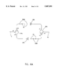
- FIG. 1 is a description of a prior art bidirectional amplifier
- FIG. 2A is a schematic showing the preferred embodiment of the present invention.
- FIG. 2B is a flow diagram showing the light paths of the counter-propagating light beams
- FIG. 3 is a more detailed description of the preferred embodiment
- FIG. 4A is a schematic showing an alternative embodiment of the present invention.
- FIG. 4B is a flow diagram showing the light paths of the counter-propagating light beams
- FIG. 5 is a schematic showing a different implementation of the present invention.
- FIG. 6A is a schematic showing a third implementation of the present invention.
- FIG. 6B is a flow diagram showing the light paths of the counter-propagating light beams.
- FIG. 7 is a schematic of a rare earth doped fiber amplifier with equal gain at multiple wavelengths.
- FIG. 2A there is shown a schematic of the preferred embodiment of the present inventive fiber amplifier comprising an input fiber 10 connected to a first port P1 of a four port optical circulator 5, an output fiber 12 connected to the third port P3 of the circulator 5, a first amplifying fiber 6A, the first end of the amplifying fiber 6 being connected to the second port P2 of the circulator 5 and the second end of the amplifying fiber 6 being connected to a pump laser 4A, a second amplifying fiber 6B, the first end of this second amplifying fiber 6B being connected to the fourth port P4 of the circulator 5 and the second end of the second fiber 6B being connected to a second pump laser 4B.
- a multiplicity of gratings 3A is written using methods well known in the art such as the exposure to two interfering beams of ultraviolet radiation.
- a multiplicity of gratings 3B is written.
- the spatial periods of gratings 3A are made such that each of the gratings 3A in the first amplifying fiber 6A reflects at a wavelength Wi from a first multiplicity of wavelengths.
- the spatial periods of gratings 3B are made such that each of the gratings 3B in the second amplifying fiber 6B reflects at a wavelength Wj from a second distinct multiplicity of wavelengths.
- the ordering of the gratings starting from the fiber end closest to the circulator, and the reflectivity of the gratings 3A and 3B is chosen in a specific manner described hereafter.
- the fiber segment lengths between the individual gratings 3A and between the gratings 3B is also chosen in a specific manner. It is well known that the amplification experienced by light propagating in a pumped rare earth doped fiber varies depending on the wavelength. Let Gi be the gain experienced by light at wavelength Wi after propagating a length Di in the fiber starting at the circulator 5, being reflected by a grating with reflectivity Ri positioned at a fiber length Di from the circulator and propagating back to the circulator.
- the length Di is chosen so that the product GiRi is the same for all wavelengths in the amplifier operating range. Taking the specific example of three wavelengths W1, W2, W3 with corresponding gain coefficients per unit length g1, g2, g3 such that g3 is larger than g2 and g2 larger than g1. It is clear that the lengths D1, D2, D3 are to be chosen such that D3 is smaller than D2 and D2 smaller than D1 so that the gains G1, G2, G3 come out equal. This result determines the ordering of the gratings 3 at wavelengths W1, W2, W3.
- the reflectivities of the gratings 3 can also be varied by increasing or decreasing the UV exposure when writing the gratings into the fiber. Varying the reflectivities or varying the ordering of the gratings may each be sufficient to provide equal amplification at all wavelengths, however it may be more convenient to vary both the ordering, the lengths Di as well as the reflectivities Ri to achieve equal amplification.
- FIG. 2B there is shown in dashed lines the paths of two light beams at wavelengths W1 and W3 propagating in the right to left direction and two other light beams at wavelengths W2 and W4 propagating in the left to right direction.
- FIG. 3 there is shown the schematic of a particular embodiment wherein the first port of circulator 106 and second port of circulator 105 are connected via fiber 14A.
- the light at a first set of wavelengths enters the amplifier through the input fiber 10 and is channeled to the amplifying fiber 6A by the circulators 105 and 106 then reflected back, one wavelength from each corresponding grating 3A, into the circulator 106 then back out to fiber 12.
- the light at a second set of wavelengths enters from the output fiber 12 in a direction counter-propagating to the first set of wavelengths, is channeled to the second amplifying fiber 6B by the circulators 106 and 105, reflected back to the circulator 105 by the set of gratings 3B and out to fiber 12.
- Pump laser 4A is connected to the distal end of the amplifying fiber 6A as in the first embodiment.
- Pump laser 4B is connected to the distal end of the amplifying fiber 6B as in the first embodiment.
- the coupling of the pump light from the pump lasers 108 and 109 into the amplifying fiber 6B is done by utilizing wavelength sensitive couplers 9A and 9B thus enabling the choice of pumping the amplifier from either the proximal or the distal end relative to the circulator 107, or alternatively to pump simultaneously from both ends of the fiber 6B in order to increase the pump power available to the amplifier.
- the couplers 9A and 9B available commercially from manufacturers such as Gould Inc. of New Jersey usually have three or four fiber ports. At least one of the ports of the couplers 9A and 9B may be utilized to monitor the light passing through the amplifying fiber 6B by means of a photodetector 15.
- FIG. 4B there is shown in dashed lines the paths of two light beams at wavelengths W1 and W3 propagating in the right to left direction and two other light beams at wavelengths W2 and W4 propagating in the left to right direction
- FIG. 5 there is shown an embodiment of the present inventive device utilizing three port circulators 17A, 17B and 17C instead of four port circulators.
- the light at a first set of wavelengths enters the device through the input fiber 10 to port P1 of circulator 17A and is channeled to port P2 and out to port P1 of the circulator 17C which in turn channels it to the amplifying fiber 6A and gratings 3A from whence it is reflected back to the circulator 17C which channels it to the circulator 17B and out to fiber 12.
- Light at a second set of wavelengths propagating at the counter direction to the light at the first set of wavelengths enters the device through fiber 12 and is channeled by the circulator 17B to the amplifying assembly 20.
- the amplifying assembly 20 comprises a wavelength sensitive coupler 9 which couples the input light and the pump light from laser 4 into the amplifying fiber 8.
- the output of the amplifying fiber 8 goes to the third port P3 of the circulator 17A which channels the light to the fiber 10.
- the amplifying assembly 20 is a more traditional amplifier assembly and has no gain flattening capability. This embodiment may be useful in cases where flattening is not required for both counter-propagating light waves.
- FIG. 6A there is shown yet a different embodiment of the present inventive amplifier with a different arrangement of the gratings 303A and 303B.
- Light at a first set of wavelengths enters the device through the input fiber 10 and is channeled to a first circulator 27A and through it to the gratings 303A which in this case are designed to pass the first set of wavelengths and reflect at a second set of wavelengths equal to the right to left propagating set of wavelengths.
- the function of this first set of gratings 303A is to stop any light at the second set of wavelengths scattered back by the input fiber 10 or its continuation into the system transmission fiber.
- the light at the first set of wavelengths continues through a traditional amplifier 20A to the second circulator 27B and out to fiber 12.
- the amplifying assembly 20 is a more traditional amplifier assembly and has no gain flattening capability, however an additional set of gratings 23 is added to attenuate individual wavelengths by the appropriate amount so that all wavelengths emerge from the amplifiers 20A or 20B with equal powers.
- FIG. 6B there is shown in dashed lines the paths of two light beams at wavelengths W1 and W3 propagating in the right to left direction and two other light beams at wavelengths W2 and W4 propagating in the left to right direction.
- FIG. 7 there is shown a schematic of a simpler optical amplifier with equal gain at multiple wavelengths.
- the amplifier of FIG. 7 is designed for one-directional amplification and comprises an input fiber 10 connected to the first port of a three port circulator 55, an output fiber 12 connected to the third port of the circulator 55, a rare earth doped fiber 6 with a first end connected to the second port of circulator 55 and a second end connected to a pump laser 4, a set of fiber gratings 3 located in the doped fiber 6 at locations selected such that when light at a wavelength Wi propagates through the doped fiber 6, is reflected by the corresponding grating and propagates back to the circulator the light experiences an amplification independent of the wavelength Wi.
Abstract
Description
Claims (12)
Priority Applications (3)
| Application Number | Priority Date | Filing Date | Title |
|---|---|---|---|
| US08/896,930 US5887091A (en) | 1997-07-18 | 1997-07-18 | Bidirectional optical amplifier having flat gain |
| PCT/US1998/020762 WO2000020907A1 (en) | 1997-07-18 | 1998-10-02 | Bidirectional optical amplifier having flat gain |
| AU97828/98A AU9782898A (en) | 1997-07-18 | 1998-10-02 | Bidirectional optical amplifier having flat gain |
Applications Claiming Priority (2)
| Application Number | Priority Date | Filing Date | Title |
|---|---|---|---|
| US08/896,930 US5887091A (en) | 1997-07-18 | 1997-07-18 | Bidirectional optical amplifier having flat gain |
| PCT/US1998/020762 WO2000020907A1 (en) | 1997-07-18 | 1998-10-02 | Bidirectional optical amplifier having flat gain |
Publications (1)
| Publication Number | Publication Date |
|---|---|
| US5887091A true US5887091A (en) | 1999-03-23 |
Family
ID=25407078
Family Applications (1)
| Application Number | Title | Priority Date | Filing Date |
|---|---|---|---|
| US08/896,930 Expired - Fee Related US5887091A (en) | 1997-07-18 | 1997-07-18 | Bidirectional optical amplifier having flat gain |
Country Status (1)
| Country | Link |
|---|---|
| US (1) | US5887091A (en) |
Cited By (14)
| Publication number | Priority date | Publication date | Assignee | Title |
|---|---|---|---|---|
| US5999309A (en) * | 1997-08-26 | 1999-12-07 | Samsung Electronics Co., Ltd. | Optical pulse amplifier |
| US6041152A (en) * | 1997-09-02 | 2000-03-21 | Amphenol Corporation | Multi-channel fiber optic communications system and multiplexer/demultiplexer arrangement therefor |
| US6212000B1 (en) * | 1998-01-14 | 2001-04-03 | Nec Corporation | Two-way optical amplifier module |
| US6215922B1 (en) * | 1997-02-07 | 2001-04-10 | Oki Electric Industry Co., Ltd. | Lightwave filter and lightwave selective router |
| US6243177B1 (en) | 2000-10-03 | 2001-06-05 | Seneca Networks, Inc. | Bidirectional WDM optical communication system with bidirectional add-drop multiplexing |
| US6377393B1 (en) * | 1998-11-13 | 2002-04-23 | Nec Corporation | Optical amplifier apparatus, optical transmission apparatus equipped with break point detecting function using optical amplifier apparatus, and bidirectional optical transmission apparatus |
| US6459528B1 (en) | 2000-05-23 | 2002-10-01 | Avanex Corporation | Optical passive components and bi-directional amplifier |
| US6480312B1 (en) * | 1997-12-16 | 2002-11-12 | Sumitomo Electric Industries, Ltd. | Dispersion compensating system used for bi-directional optical communication |
| US6552844B2 (en) | 2001-06-01 | 2003-04-22 | Agere Systems Guardian Corp. | Passively output flattened optical amplifier |
| US6608709B2 (en) | 2000-10-03 | 2003-08-19 | Gary Duerksen | Bidirectional WDM optical communication system with bidirectional add-drop multiplexing |
| US20050207009A1 (en) * | 2004-03-22 | 2005-09-22 | Efimov Oleg M | Nonreciprocal optical element with independent control of transmission opposite directions |
| US20100278531A1 (en) * | 2009-05-04 | 2010-11-04 | Industrial Technology Research Institute | Optical switch and optical signal communication system |
| CN107193171A (en) * | 2016-03-15 | 2017-09-22 | 乔立杰 | Bi-directional optical amplifier |
| CN113572005A (en) * | 2021-07-27 | 2021-10-29 | 广东国志激光技术有限公司 | Multifunctional optical fiber device based on optical fiber circulator |
Citations (6)
| Publication number | Priority date | Publication date | Assignee | Title |
|---|---|---|---|---|
| US5039199A (en) * | 1989-12-29 | 1991-08-13 | At&T Bell Laboratories | Lightwave transmission system having remotely pumped quasi-distributed amplifying fibers |
| US5050949A (en) * | 1990-06-22 | 1991-09-24 | At&T Bell Laboratories | Multi-stage optical fiber amplifier |
| US5557442A (en) * | 1993-06-04 | 1996-09-17 | Ciena Corporation | Optical amplifiers with flattened gain curves |
| US5563733A (en) * | 1994-08-25 | 1996-10-08 | Matsushita Electric Industrial Co., Ltd. | Optical fiber amplifier and optical fiber transmission system |
| US5604627A (en) * | 1995-05-18 | 1997-02-18 | Robert Bosch Gmbh | Optical amplifier device |
| US5633741A (en) * | 1995-02-23 | 1997-05-27 | Lucent Technologies Inc. | Multichannel optical fiber communications |
-
1997
- 1997-07-18 US US08/896,930 patent/US5887091A/en not_active Expired - Fee Related
Patent Citations (6)
| Publication number | Priority date | Publication date | Assignee | Title |
|---|---|---|---|---|
| US5039199A (en) * | 1989-12-29 | 1991-08-13 | At&T Bell Laboratories | Lightwave transmission system having remotely pumped quasi-distributed amplifying fibers |
| US5050949A (en) * | 1990-06-22 | 1991-09-24 | At&T Bell Laboratories | Multi-stage optical fiber amplifier |
| US5557442A (en) * | 1993-06-04 | 1996-09-17 | Ciena Corporation | Optical amplifiers with flattened gain curves |
| US5563733A (en) * | 1994-08-25 | 1996-10-08 | Matsushita Electric Industrial Co., Ltd. | Optical fiber amplifier and optical fiber transmission system |
| US5633741A (en) * | 1995-02-23 | 1997-05-27 | Lucent Technologies Inc. | Multichannel optical fiber communications |
| US5604627A (en) * | 1995-05-18 | 1997-02-18 | Robert Bosch Gmbh | Optical amplifier device |
Cited By (19)
| Publication number | Priority date | Publication date | Assignee | Title |
|---|---|---|---|---|
| US6215922B1 (en) * | 1997-02-07 | 2001-04-10 | Oki Electric Industry Co., Ltd. | Lightwave filter and lightwave selective router |
| US5999309A (en) * | 1997-08-26 | 1999-12-07 | Samsung Electronics Co., Ltd. | Optical pulse amplifier |
| US6041152A (en) * | 1997-09-02 | 2000-03-21 | Amphenol Corporation | Multi-channel fiber optic communications system and multiplexer/demultiplexer arrangement therefor |
| US6480312B1 (en) * | 1997-12-16 | 2002-11-12 | Sumitomo Electric Industries, Ltd. | Dispersion compensating system used for bi-directional optical communication |
| US6212000B1 (en) * | 1998-01-14 | 2001-04-03 | Nec Corporation | Two-way optical amplifier module |
| US6377393B1 (en) * | 1998-11-13 | 2002-04-23 | Nec Corporation | Optical amplifier apparatus, optical transmission apparatus equipped with break point detecting function using optical amplifier apparatus, and bidirectional optical transmission apparatus |
| US20040051939A1 (en) * | 2000-05-23 | 2004-03-18 | Avanex Corporation | Optical passive components and bi-directional amplifier |
| US6459528B1 (en) | 2000-05-23 | 2002-10-01 | Avanex Corporation | Optical passive components and bi-directional amplifier |
| US6643056B2 (en) | 2000-05-23 | 2003-11-04 | Avanex Corporation | Optical passive components and bi-directional amplifier |
| US6243177B1 (en) | 2000-10-03 | 2001-06-05 | Seneca Networks, Inc. | Bidirectional WDM optical communication system with bidirectional add-drop multiplexing |
| US6608709B2 (en) | 2000-10-03 | 2003-08-19 | Gary Duerksen | Bidirectional WDM optical communication system with bidirectional add-drop multiplexing |
| US6552844B2 (en) | 2001-06-01 | 2003-04-22 | Agere Systems Guardian Corp. | Passively output flattened optical amplifier |
| US20050207009A1 (en) * | 2004-03-22 | 2005-09-22 | Efimov Oleg M | Nonreciprocal optical element with independent control of transmission opposite directions |
| US6965472B2 (en) * | 2004-03-22 | 2005-11-15 | Raytheon Company | Nonreciprocal optical element with independent control of transmission opposite directions |
| US20100278531A1 (en) * | 2009-05-04 | 2010-11-04 | Industrial Technology Research Institute | Optical switch and optical signal communication system |
| US8111989B2 (en) * | 2009-05-04 | 2012-02-07 | Industrial Technology Research Institute | Optical switch and optical signal communication system |
| CN107193171A (en) * | 2016-03-15 | 2017-09-22 | 乔立杰 | Bi-directional optical amplifier |
| CN107193171B (en) * | 2016-03-15 | 2020-12-25 | 乔立杰 | Bidirectional optical amplifier |
| CN113572005A (en) * | 2021-07-27 | 2021-10-29 | 广东国志激光技术有限公司 | Multifunctional optical fiber device based on optical fiber circulator |
Similar Documents
| Publication | Publication Date | Title |
|---|---|---|
| EP1103107B1 (en) | Bidirectional dispersion compensation system | |
| US5887091A (en) | Bidirectional optical amplifier having flat gain | |
| US5917635A (en) | Optical repeaters for single-and multi-wavelength operation with dispersion equalization | |
| KR100247665B1 (en) | Gain control for optically amplified systems | |
| US5933270A (en) | Optical equalizer | |
| US6931196B2 (en) | Optical device including dynamic channel equalization | |
| US5978131A (en) | In-fiber two-stage amplifier providing WDM signal conditioning | |
| EP1013021A1 (en) | Dynamic optical amplifier | |
| GB2315380A (en) | Optical add/drop circuit using fibre gratings | |
| CA2254830A1 (en) | Spectral equalizer for multiplexed channels | |
| US6204958B1 (en) | Optical amplifier having a substantially flat gain spectrum | |
| US6552834B2 (en) | Methods and apparatus for preventing deadbands in an optical communication system | |
| US7019893B2 (en) | Optical dynamic gain amplifier | |
| US6917747B2 (en) | Compact hybrid integrated optical dynamic channel equalizer | |
| US6381049B1 (en) | Multi-port optical multiplexer element | |
| US6738183B2 (en) | Optical filter functioning as both a gain equalizer and noise-light blocking filter | |
| US6952509B2 (en) | Wavelength dispersion compensator and optical transmission line | |
| WO2000020907A1 (en) | Bidirectional optical amplifier having flat gain | |
| TW407218B (en) | Multi-channel optical fiber dispersion compensator | |
| US6697575B1 (en) | System and method for increasing capacity of long-haul optical transmission systems | |
| KR100396266B1 (en) | Gain flattening device of a fiber amplifier | |
| JPH09167995A (en) | Optical transmission line compensator and optical wavelength multiplex transmission system | |
| US20040052529A1 (en) | WDM transmission link design | |
| WO1999000924A1 (en) | Dynamic optical amplifier | |
| EP1654816B1 (en) | Wavelength-selective optical signal processing device |
Legal Events
| Date | Code | Title | Description |
|---|---|---|---|
| AS | Assignment |
Owner name: DITECH CORPORATION, CALIFORNIA Free format text: ASSIGNMENT OF ASSIGNORS INTEREST;ASSIGNORS:JABR. SALIM N.;FARBER, GENNADY I.;VETTER, EDWARD A.;AND OTHERS;REEL/FRAME:008725/0313 Effective date: 19970717 |
|
| AS | Assignment |
Owner name: DITECH CORPORATION, CALIFORNIA Free format text: ASSIGNMENT OF ASSIGNORS INTEREST;ASSIGNORS:JABR, SALIM N.;FARBER, GENNADY I.;VETTER, EDWARD A.;AND OTHERS;REEL/FRAME:009101/0290 Effective date: 19970717 |
|
| REMI | Maintenance fee reminder mailed | ||
| FPAY | Fee payment |
Year of fee payment: 4 |
|
| SULP | Surcharge for late payment | ||
| AS | Assignment |
Owner name: JDS UNIPHASE CORPORATION, CALIFORNIA Free format text: ASSIGNMENT OF ASSIGNORS INTEREST;ASSIGNOR:DITECH COMMUNICATIONS CORPORATION;REEL/FRAME:014805/0852 Effective date: 20030716 |
|
| FEPP | Fee payment procedure |
Free format text: PAT HOLDER NO LONGER CLAIMS SMALL ENTITY STATUS, ENTITY STATUS SET TO UNDISCOUNTED (ORIGINAL EVENT CODE: STOL); ENTITY STATUS OF PATENT OWNER: LARGE ENTITY |
|
| FEPP | Fee payment procedure |
Free format text: ENTITY STATUS SET TO UNDISCOUNTED (ORIGINAL EVENT CODE: BIG.); ENTITY STATUS OF PATENT OWNER: LARGE ENTITY |
|
| FPAY | Fee payment |
Year of fee payment: 8 |
|
| REMI | Maintenance fee reminder mailed | ||
| LAPS | Lapse for failure to pay maintenance fees | ||
| STCH | Information on status: patent discontinuation |
Free format text: PATENT EXPIRED DUE TO NONPAYMENT OF MAINTENANCE FEES UNDER 37 CFR 1.362 |
|
| FP | Lapsed due to failure to pay maintenance fee |
Effective date: 20110323 |
|
| FEPP | Fee payment procedure |
Free format text: PAYOR NUMBER ASSIGNED (ORIGINAL EVENT CODE: ASPN); ENTITY STATUS OF PATENT OWNER: LARGE ENTITY |