US5890537A - Wiper plug launching system for cementing casing and liners - Google Patents
Wiper plug launching system for cementing casing and liners Download PDFInfo
- Publication number
- US5890537A US5890537A US08/805,782 US80578297A US5890537A US 5890537 A US5890537 A US 5890537A US 80578297 A US80578297 A US 80578297A US 5890537 A US5890537 A US 5890537A
- Authority
- US
- United States
- Prior art keywords
- plug
- dart
- rod
- wiper
- liner
- Prior art date
- Legal status (The legal status is an assumption and is not a legal conclusion. Google has not performed a legal analysis and makes no representation as to the accuracy of the status listed.)
- Expired - Lifetime
Links
- 239000004568 cement Substances 0.000 claims abstract description 52
- 239000012530 fluid Substances 0.000 claims abstract description 45
- 229920001971 elastomer Polymers 0.000 claims abstract description 15
- 239000000806 elastomer Substances 0.000 claims abstract description 15
- 238000007789 sealing Methods 0.000 claims abstract description 3
- 125000006850 spacer group Chemical group 0.000 claims description 16
- 239000002002 slurry Substances 0.000 claims description 14
- 238000005086 pumping Methods 0.000 claims description 12
- 238000000926 separation method Methods 0.000 claims description 12
- 238000000034 method Methods 0.000 claims description 11
- 230000002093 peripheral effect Effects 0.000 claims description 3
- 230000035939 shock Effects 0.000 claims description 3
- 230000000979 retarding effect Effects 0.000 claims 2
- 238000010521 absorption reaction Methods 0.000 claims 1
- 238000012986 modification Methods 0.000 abstract description 3
- 230000004048 modification Effects 0.000 abstract description 3
- 238000005553 drilling Methods 0.000 description 14
- 238000011109 contamination Methods 0.000 description 5
- 230000015572 biosynthetic process Effects 0.000 description 3
- 238000006073 displacement reaction Methods 0.000 description 3
- 239000010720 hydraulic oil Substances 0.000 description 3
- 241000282472 Canis lupus familiaris Species 0.000 description 2
- 230000008901 benefit Effects 0.000 description 2
- 230000003750 conditioning effect Effects 0.000 description 2
- 230000005012 migration Effects 0.000 description 2
- 238000013508 migration Methods 0.000 description 2
- 239000003921 oil Substances 0.000 description 2
- 238000003825 pressing Methods 0.000 description 2
- 229910000831 Steel Inorganic materials 0.000 description 1
- 230000009471 action Effects 0.000 description 1
- 238000004873 anchoring Methods 0.000 description 1
- 230000000712 assembly Effects 0.000 description 1
- 238000000429 assembly Methods 0.000 description 1
- 238000004140 cleaning Methods 0.000 description 1
- 238000005520 cutting process Methods 0.000 description 1
- 238000013461 design Methods 0.000 description 1
- 230000000694 effects Effects 0.000 description 1
- 238000007667 floating Methods 0.000 description 1
- 230000002706 hydrostatic effect Effects 0.000 description 1
- 238000004519 manufacturing process Methods 0.000 description 1
- 230000007246 mechanism Effects 0.000 description 1
- ORQBXQOJMQIAOY-UHFFFAOYSA-N nobelium Chemical compound [No] ORQBXQOJMQIAOY-UHFFFAOYSA-N 0.000 description 1
- 238000012856 packing Methods 0.000 description 1
- 239000003208 petroleum Substances 0.000 description 1
- 230000008569 process Effects 0.000 description 1
- 239000011435 rock Substances 0.000 description 1
- 238000010008 shearing Methods 0.000 description 1
- 239000010959 steel Substances 0.000 description 1
Images


Classifications
-
- E—FIXED CONSTRUCTIONS
- E21—EARTH DRILLING; MINING
- E21B—EARTH DRILLING, e.g. DEEP DRILLING; OBTAINING OIL, GAS, WATER, SOLUBLE OR MELTABLE MATERIALS OR A SLURRY OF MINERALS FROM WELLS
- E21B33/00—Sealing or packing boreholes or wells
- E21B33/10—Sealing or packing boreholes or wells in the borehole
- E21B33/13—Methods or devices for cementing, for plugging holes, crevices, or the like
- E21B33/14—Methods or devices for cementing, for plugging holes, crevices, or the like for cementing casings into boreholes
- E21B33/16—Methods or devices for cementing, for plugging holes, crevices, or the like for cementing casings into boreholes using plugs for isolating cement charge; Plugs therefor
- E21B33/165—Cementing plugs specially adapted for being released down-hole
-
- E—FIXED CONSTRUCTIONS
- E21—EARTH DRILLING; MINING
- E21B—EARTH DRILLING, e.g. DEEP DRILLING; OBTAINING OIL, GAS, WATER, SOLUBLE OR MELTABLE MATERIALS OR A SLURRY OF MINERALS FROM WELLS
- E21B33/00—Sealing or packing boreholes or wells
- E21B33/02—Surface sealing or packing
- E21B33/03—Well heads; Setting-up thereof
- E21B33/04—Casing heads; Suspending casings or tubings in well heads
- E21B33/05—Cementing-heads, e.g. having provision for introducing cementing plugs
Definitions
- This invention relates generally to the cementing of casing strings and liners in petroleum wells, and particularly to new and improved methods and apparatus for launching wiper plugs which prevent contamination of a column of cement slurry by drilling mud as the cement is being pumped into the well during a cementing operation.
- a string of steel casing or liner is lowered and set therein.
- One drillable shoe and possibly one drillable collar having an upwardly closing check valve are mounted on or near the lower end of the string to prevent back flow.
- cement slurry is pumped down the interior thereof and out into the borehole via the check valves where it flows up in the annulus outside the liner up to a desired level.
- the drilling mud that was standing in the well prior to cementing is displaced and circulated out of the well during the casing setting and cementing steps. When the cement has hardened, it seals off the annular space between the outside of the liner and the surrounding well bore wall and prevents migration of formation fluids therealong.
- the check valves in the float shoes prevent back flow of the cement into the casing or liner during the time that it takes for the cement to set up. During downward movement the outer edges of the cups of the second plug wipe or scrape the cement off of the inner walls of the liner so that no deposits are left. Once the cement has hardened, the plugs and cement shoes can be drilled out.
- wiper plugs used in cementing liners have been designed such that cement slurry and other fluids could be pumped through a flow passage in the plug itself, which requires complicated valve systems to open and close this passage.
- This complexity has created difficulties in and of itself, and has resulted in plug structures that are difficult to drill out at the end of the cementing operation.
- the inclusion of such valve structures also has reduced the performance characteristics of such plugs, particularly when the liner hanger and wiper plug launching system are utilized on directional or horizontal sections of a well.
- a person skilled-in-the-art would not run multiple plugs while cementing liners. Only the top shut-off plug would be used in most instances in order to reduce the risk of any mechanical failure.
- not having bottom wiper plugs increases substantially the risk for the cement slurry to channel through the mud inside the liner and therefore be completely contaminated before reaching the annulus. This phenomenon has been responsible for a large number of liner cementing failures.
- the general object of the present invention is to provide a new and improved plug launching system of the type described that obviates the above-mentioned problems with prior systems.
- a casing or liner cementing method including the steps of positioning lower and upper wiper plugs having elastomer cups that are inwardly compressed in an open-bottomed tubular basket near the top of the liner, the basket having an outer diameter that is less than the inner diameter of the liner to permit cement to flow therebetween, the basket having a tubular body extending upwardly therefrom; providing a push rod in the body that can move longitudinally thereof and which has a lower end engaging the upper plug, pumping a first piston or dart down into engagement with the upper end of the rod and then applying pressure to the dart to force the rod downward a selected distance to expel the lower plug from the basket and out into the liner where said cups expand to engage the liner walls and provide a separation between the lower end of a column of cement and the drilling fluids, pumping a certain volume of cement slurry into the liner with said lower plug moving downward at the lower end of the cement, pumping a second piston or
- the cement and plugs then are pumped on down the liner, and when the lower plug seats against a float collar or float shoe, a passage is opened through the plug to enable the cement to flow into the annulus.
- the displacement is complete.
- the basket and body assembly then is retrieved to the surface so that the inside of the liner is unobstructed.
- Apparatus in accordance with this invention includes a tubular body having a cylindrical, open-bottomed basket mounted on its lower end.
- Lower and upper elastomeric wiper plugs are force-fitted into the basket, which temporarily reduces their respective outer diameters.
- a push rod is mounted for longitudinal movement in the body with its lower end in engagement with the upper plug.
- the upper end of such rod is adapted to be engaged by a first dart or piston that is pumped down the running string and into the body in order to drive the rod and both wiper plugs downward until the lower plug is expelled from the basket.
- the plug Upon expulsion, the plug expands radially outward to its relaxed diameter where the outer edges of its cups engage the inner walls of the liner.
- This plug then moves ahead of a column of cement which is being pumped down the running string and out of lateral ports in the body above the rod. From there the cement flows through the annular space between the basket and the inner wall of the liner. At the appropriate time a second dart or piston is pumped down into the body and engages the first dart. Fluid pressure then is applied to drive the two darts and the rod further downward until the upper wiper plug also is expelled from the basket and launched into the liner at the upper end of the column of cement. This plug expands like the first one to provide a moving seal that prevents contamination of the upper end of the cement column. When the cementing is complete, means are provided to enable the body, the basket, the drive rod and the darts to be retrieved to the surface.
- An important feature of the launching tool comprises an upper tubular housing having lateral ports with a slidable sleeve valve mounted within the housing and slidable in the bore of the housing to close or partially close the ports upon downward movement, and to reopen the ports upon movement of a dart past the lateral openings and a return upward movement of the sleeve valve.
- a slidable sleeve valve mounted within the housing and slidable in the bore of the housing to close or partially close the ports upon downward movement, and to reopen the ports upon movement of a dart past the lateral openings and a return upward movement of the sleeve valve.
- Another feature includes a drive rod for ejection of a wiper plug.
- the drive rod extends within a cylinder tube and within a spacer tube mounted over the cylinder tool.
- An enlarged diameter upper head or piston of the drive rod is received within the spacer tube and a lower piston of the drive rod is mounted within the cylinder tube.
- a predetermined clearance is provided between the outer diameter of the lower piston and the adjacent inner peripheral surface of the cylinder tube to provide metering of hydraulic fluid as the drive rod is forced downwardly by a dart engaging the enlarged diameter upper head of the drive rod thereby to cushion the downward movement of the drive rod for ejection of a wiper plug.
- FIG. 1 is a schematic view of a casing or liner being cemented in a borehole using methods and equipment in accordance with this invention
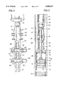
- FIG. 2 is a longitudinal cross-sectional view of the plug launching tool of FIG. 1;
- FIG. 3 is a longitudinal sectional view of a surface tool by which the darts or pistons are launched to operate the plug launching tool of FIG. 2;
- FIG. 4 is a fragmentary sectional view showing a piston bearing down against the top of the launching rod to shift it downward;
- FIG. 5 is a view similar to FIG. 2 showing ejection on the lower wiper plug
- FIG. 6 is a longitudinal sectional view showing the second dart or piston engaging the first to cause ejection of the upper wiper plug;
- FIGS. 7 and 8 are views showing the structure and operation of the spacers between the plugs.
- FIGS. 9-11 are sectional views of a separate embodiment of the invention in which three wiper plugs are utilized.
- a borehole 10 that has been drilled into the earth from an offshore or on land rig has a length of liner 12 disposed therein.
- the liner 12 is suspended by a hanger indicated generally at 14 that is positioned in the lower portion of the casing 13 that was previously run and cemented in place.
- the drilling is done using a well-head assembly that in a subsea location is mounted by a base on the sea floor.
- Various blowout preventers and valves in the well-head are controlled remotely from a vessel or rig by hydraulic lines.
- the term "liner" as used herein means a well casing whose upper end does not extend all the way to the surface, but is hung off down hole in a larger diameter casing string.
- Drillable float shoes or collars 16 and 16' are attached to the lower end of the liner 12 and include an upwardly closing check valves to prevent reverse flow of cement once it has been pumped through the check valves and into the annulus 11 that is formed between the outer diameter of the liner 12 and the walls of the borehole 10.
- the purpose of the cementing operation is to fill the annulus 11 with cement which then hardens to seal off the annulus so that fluids in the formation rocks that have been penetrated by the borehole 10 can not migrate therealong.
- a portion of the liner 12 can be perforated to bring the well into production, or a smaller diameter borehole can be drilled below the borehole 10 and then lined and cemented to deepen the well.
- a weighted drilling fluid or "mud” that has a hydrostatic head which overbalances the formation fluid pressure to prevent a blowout.
- the mud is circulated to remove cuttings produced by the rotary drilling process.
- wiper plugs are positioned at the lower and upper ends of the slurry column to maintain separations.
- Each plug bridges the bore of the liner 12 and has a plurality of axially spaced elastomeric cups that face upward. The outer edge of each cup is sized to sealingly engage the inner walls of the liner 12 while sliding downward therealong.
- a plug launching tool indicated generally at 20 in FIG. 1 is attached to the lower end of the mandrel 21 of the hanger setting tool 14 that is connected to the lower end of a running string 22 of drill pipe.
- the hanger 14 has sets of slips 23, 24 that have serrations or teeth which bite into and grip the casing wall when wedged outward by expander cones 25, 26.
- Latch dogs 27 and a seal-carrying ring 28 are located between the mandrel 21 and the body 29 of the hanger assembly 14, and a releasable nut 30 couples the body to the running string 22.
- the plug launcher 20 which is connected to the lower end of the mandrel 21 by a collar connector 31, includes an elongated generally tubular body 32 whose lower end is connected to a cylindrical housing or basket 33 which has an open lower end.
- Upper and lower wiper plugs 34, 35 are loaded into the basket 33 during assembly, and are forced into the basket so that elastomer cups are compressed and folded upward to a reduced diameter.
- the plugs 34, 35 are adapted to be driven sequentially therefrom and into the bore of or the liner 12 by an elongated rod 36 whose upper end is arranged to be engaged by pistons or darts that have been pumped down the running string 22 and the mandrel 21 from the vessel or rig.
- the first piston or dart that is pumped down drives the rod 36 and both of the plugs 34, 35 down sufficiently to eject only the lower plug from the basket 33, where its cups expand to provide the lower wiper plug.
- a known volume of cement has been pumped into the running string 22 where it flows into the liner 12 via the lateral ports 38 and the annular space between the basket 33 and the surrounding inner walls of the liner
- another piston or dart is pumped from the surface down into engagement with the first dart. Pressure then is applied to force the rod 36 further down and thereby eject the upper wiper plug 34 so that its elastomer cups expand and engage the inner wall of the liner as it follows the upper end of the cement downward.
- the body 32 of the launching tool 20 includes an upper tubular housing 40 whose upper end is threaded to the mandrel 21 of the liner setting tool 14, and whose lower end is threaded at 41 to a spacer tube 42.
- a plurality of ports 43 equalize pressures inside and outside the tube 42.
- a sleeve valve 44 which is slidable in the bore 45 of the housing 40 is biased upward to a normally open position with respect to the ports 38 by a coil spring 46 that reacts between an inwardly extending shoulder 47 on the housing 40 and an outwardly directed shoulder 48 on the upper end of the sleeve valve 44 which also carries a seal ring as shown.
- cement slurry or other fluids can be pumped down the bore of sleeve valve 44 and into the annular space outside the tool 20 via the ports 38.
- the sleeve valve 44 can be moved downward against the bias afforded by the coil spring 46 to a position when its lower end portion partially closes off the ports 38.
- the enlarged diameter head or upper piston 50 of the drive rod 36 slides in the bore 51 of the spacer tube 42.
- a collar 54 connects the spacer tube 42 to the upper end of a cylinder tube 55.
- the upper portion 52 of the rod 36 extends through a bore 56 in the collar 54, and one or more seal rings 57 prevent fluid leakage.
- An enlarged diameter lower piston 58 is formed on the rod 36 between its ends, and slides within the bore 60 of the cylinder tube 55.
- the annular chamber formed between the lower portion 52' of the rod 36 and the inner wall of the tube 55 is filled with a suitable hydraulic oil.
- the piston 58 has an outer diameter that provides a selected clearance with respect to the wall of the bore 60 such that, as the piston is forced downward with the rod 36, a metering effect is created which retards the rate of downward movement and prevents shock loads from being applied to the wiper plugs 34 and 35.
- the lower end of the cylinder tube 55 is connected by threads to an enlarged diameter cap 63 which is, in turn, fixed to the upper end of the basket 33 by radial pins 64 or the like.
- the cap 63 has a central bore that slidably receives the lower end portion 52' of the drive rod 36. Seals 65 are provided to prevent leakage of hydraulic oil.
- a drive disc 66 forms the lower end of the rod 36.
- the basket 33 initially houses the upper and lower wiper plugs 34, 35 within the bore thereof, and is provided with a plurality of longitudinal slots 68 that receive radial stop pins 70 which extend from the outer periphery of a drive flange 75 that rests on top of the upper plug 34.
- a head 71 on the upper end of the upper plug 34 has an annular recess 72 which receives the inner ends of several radially extending shear pins 73 on the drive flange 75 to releasably couple the plug 34 to the flange.
- the lower end of the plug 34 is separated from the upper end of the lower plug 35 by several spacer mechanisms 74 to be described in more detail below.
- Each of the wiper plugs 34, 35 comprises a plurality of axially spaced, annular elastomer cups 76 that face upwardly.
- the cups 76 made of an elastomer are molded onto a central core.
- the relaxed diameter of each cup 76 is slightly greater than the inner diameter of the liner 12 so that the lip of each cup slides and seals against the inner walls of the liner to maintain a separation between fluids above and below the plug.
- the plugs 34, 35 are forcefully loaded into the basket 33 prior to being positioned in the well, and during such loading the cups 76 are deformed radially inward to a diameter that is substantially less than the inner diameter of the liner 12.
- each spacer 74 includes a generally rectangular bar 82 that has a tang 83 on its outer side which extends through a slot 80.
- a transverse pin 84 on the head of the tang 83 limits inward movement.
- the thicknesses of the bars 82 provide an axial separation of the adjacent ends of the plugs 34, 35 to prevent them from sticking together.
- the spacers 74 also move downward from the phantom line position until the bottom plug 35 is ejected from the basket 33. At this point the heads of the tangs 83 encounter the lower end surfaces of the slots 80, and the bars 82 each pivot downward to the solid line positions where the tangs are received in recesses 85. Then the bore of the basket 33 is completely unobstructed during ejection and release of the top wiper plug 34.
- a window 86 is provided at the top of each slot 80 to provide a space through which the pin 84 can be inserted during initial assembly.
- the plug launching tool 32 of the present invention is remotely operated by releasing pistons or darts from a launcher 90 above the drilling rig floor and then pumping them down the running string 22.
- the dart launcher 90 includes a generally tubular body 91 whose upper end is connected to a lifting sub 92 by which the body is suspended from the elevators of the rig.
- a swivel housing 93 that is rotatably mounted on the body 91 has several fluid inlets 94 that communicate with the bore of the body via radial ports 95.
- Upper and lower tubular receivers 96, 97 which temporarily house the darts 100, 101 are mounting in the body 91 above upper and lower rotatable plug valve elements 102, 103, respectively.
- the darts 100, 101 are each standard devices having several upwardly facing, elastomer swab cups that hold pressure from above.
- Each valve element 102, 103 has a passageway 104 that is large enough to pass a dart 100, 101 when the passageway is longitudinally aligned with the bore of a receiver.
- Suitable actuators 107, 108 are provided to selectively rotate the plug valve elements 102, 103.
- the plug valve elements 102, 103 each have kidney-shaped external recesses on opposite sides of the passageways 104 which allow fluids to bypass outside the receivers 96, 97 when the passageways are at right angles to the receivers. This allows fluids to be pumped under pressure into the running string 22 with the darts 100, 101 caged. However when the bypass passages 104 are closed by rotating a valve element until its bore is in alignment with a receiver, pump pressure through inlets 94 forces a dart 100 or 101 out of its receiver, through a valve element and into the running string 22 where it travels down into the upper housing 40 of the wiper plug launcher 20.
- the liner 12 is run and suspended by the hanger 14 from a point near the lower end of the casing 13 which is below the wellhead.
- the hanger 14 is activated by appropriate manipulation of the running string 22, after which the housing 29 is lowered somewhat to cause the cones 25 and 26 to expand the slips 23, 24 into anchoring engagement with the casing 13.
- the plug launcher tool 20 of the present invention is connected to the lower end of the mandrel 21 as shown in FIG. 1, and the wiper plugs 34 and 35 were previously loaded into the basket 33.
- the drive rod 36 is in its upper position where the piston 58 is at the upper end of the oil chamber 60.
- the ports 38 in the housing 40 are open so that fluids can flow therethrough.
- the running string 22 is coupled to the hanger housing 29 by the nut 30 and the latch dogs 27, and the packing ring 28 prevents any fluid flow up into the casing 13 from the liner 12.
- the dart launching tool 90 with the two darts 100, 101 loaded into the receivers 96, 97 is connected at the surface between the lifting sub 92 and the upper end of the running string 22.
- the plug valves 102, 103 are rotated by their actuators to positions that prevent release at the darts 100, 101 while allowing fluid that is pumped in through the swivel inlets 94 to bypass the receivers 96, 97 and the darts and flow down into the running string 22.
- conditioning fluids can be circulated down the liner 12 and back up through the annulus outside it to clean up the well 10.
- the plug 35 is pumped down ahead of the cement column to prevent contamination by fluids in the liner 12.
- the top cup of the dart 101 clears the bottom of the sleeve valve 44 so that the ports 38 are re-opened as the sleeve valve is shifted upward by the coil spring 46.
- the spacers 74 pivot downward to their out-of-the-way positions as shown in FIG. 8 so that the bore of the basket 33 below the plug 34 is unobstructed. Pumping of cement is continued until the desired number of barrels of cement has been placed within the liner 12.
- the lower plug 35 reaches the float collar 16', it is stopped thereby and a frangible disc or the like (not shown) in its core ruptures automatically to allow cement to pass on through it.
- the upper plug valve 102 of the dart launcher 90 When the proper amount of cement has been pumped into the running string 22, the upper plug valve 102 of the dart launcher 90 is rotated into alignment with the upper dart 100, which blocks bypass flow and enables this dart to be forced into the drill pipe 22, followed by whatever fluid is being pumped behind it.
- the dart 100 travels down through the running string 22, the mandrel 21, and into the housing 40.
- the valve sleeve 44 shifts downward to close off the lateral ports 38.
- the dart 100 then engages the lower dart 101, so that applied pressures force the drive rod 36 further down in the body 32 as shown in FIG. 6.
- the pins 73 are sheared so that the drive disc 66 on the lower end of the rod 32 passes through the plate 75 and forces ejection of the upper wiper plug 34 from the bottom of the basket 33.
- the cups 76 of this plug then resile outward to seal off the cross-section of the liner bore.
- the metering of oil past the piston 58 again slows or retards downward movement of the rod 32 so that ejection is smoothed.
- the valve sleeve again opens, as before, so that displacement fluids flow around the outside of the launcher assembly 20 and through the annular space between the basket 33 and the inner wall of the liner 12.
- the upper plug 34 also provides a separation so that the cement is not contaminated by such fluids.
- a positive indication of the launching of wipers plugs 34 and 35 from basket 33 is shown by an increase in pumping pressure at the surface location resulting from the cushioned travel of piston 58 for both plugs 34 and 35.
- the shearing of pins 73 for upper plug 34 additional increases the pumping pressure for upper plug 34.
- the increase in the pumping pressure may amount to about 1500 psi for lower plug 35 and to about 3000 psi for upper plug 34.
- the liner setting tool is released by appropriate manipulation so that it, the plug launching tool 20, and the running string 22, can be removed from the well. If deeper drilling is desired, a bit on a drill string can be used to drill out the plugs 34, 35 , the float equipment 16, 16' and any cement remaining in the lowermost end portion of the liner 12.
- the plug launcher tool 20 is entirely reusable by loading new wiper plugs into the basket 33, and replacing the shear pins 73.
- the darts 100, 101 are removed from the tool 20 and repositioned in the dart launcher 90.
- fluids other than drilling fluids may be pumped downhole for various purposes, such as cleaning or conditioning fluids for example.
- a separate fluid or fluids may be positioned between the drilling fluid and the cement slurry. For this reason, it may be desirable to have more than two plugs for separation of the several different fluids.
- a plug launching includes three wiper plugs mounted within a basket defining an upper wiper plug 34A, an intermediate wiper plug 35A, and a lower wiper plug 37A.
- a driving flange 75A is positioned above plug 34A and includes shear pins 73A.
- Rod 36A and metering piston 60A function in the same manner as rod 36 and metering piston 60 in the embodiment of FIGS. 1-8.
- Spacers 74A are positioned between wiper plugs 34A, 35A and 37A.
- launcher 90A at a surface location such as a floating vessel, for example, has a drill pipe string 22A for extending downwardly within liner 12A which may be on the sea floor in a subsea operation, for example.
- Three darts 100A, 101A and 102A are mounted within respective tubular receivers 96A, 97A and 98A.
- Plug valve assemblies 103A are positioned between pistons or darts 100A, 101A and 102A. Pistons or darts 100A, 101A and 102A are released in sequence in a manner similar to the embodiment of FIGS. 1-8.
- Sleeve valve 44A for ports 38A is provided.
- plugs 34A, 35A, and 37A are effective to provide separation between four different fluids. It is of course apparent that additional plugs may be added, if desired, and launched in accordance with the present invention.
Abstract
Description
Claims (19)
Priority Applications (1)
| Application Number | Priority Date | Filing Date | Title |
|---|---|---|---|
| US08/805,782 US5890537A (en) | 1996-08-13 | 1997-02-25 | Wiper plug launching system for cementing casing and liners |
Applications Claiming Priority (2)
| Application Number | Priority Date | Filing Date | Title |
|---|---|---|---|
| US2388696P | 1996-08-13 | 1996-08-13 | |
| US08/805,782 US5890537A (en) | 1996-08-13 | 1997-02-25 | Wiper plug launching system for cementing casing and liners |
Publications (1)
| Publication Number | Publication Date |
|---|---|
| US5890537A true US5890537A (en) | 1999-04-06 |
Family
ID=26697730
Family Applications (1)
| Application Number | Title | Priority Date | Filing Date |
|---|---|---|---|
| US08/805,782 Expired - Lifetime US5890537A (en) | 1996-08-13 | 1997-02-25 | Wiper plug launching system for cementing casing and liners |
Country Status (1)
| Country | Link |
|---|---|
| US (1) | US5890537A (en) |
Cited By (74)
| Publication number | Priority date | Publication date | Assignee | Title |
|---|---|---|---|---|
| GB2343467A (en) * | 1998-11-02 | 2000-05-10 | Baker Hughes Inc | Wiper plug launching tool |
| US6167963B1 (en) * | 1998-05-08 | 2001-01-02 | Baker Hughes Incorporated | Removable non-metallic bridge plug or packer |
| US20020104656A1 (en) * | 2001-01-19 | 2002-08-08 | Ian Murley | System for cementing a liner of a subterranean well |
| US6431626B1 (en) * | 1999-04-09 | 2002-08-13 | Frankis Casing Crew And Rental Tools, Inc. | Tubular running tool |
| US6672384B2 (en) * | 2002-01-31 | 2004-01-06 | Weatherford/Lamb, Inc. | Plug-dropping container for releasing a plug into a wellbore |
| US20040055741A1 (en) * | 2002-01-31 | 2004-03-25 | Weatherford/Lamb, Inc. | Plug-dropping container for releasing a plug into a wellbore |
| US6712153B2 (en) | 2001-06-27 | 2004-03-30 | Weatherford/Lamb, Inc. | Resin impregnated continuous fiber plug with non-metallic element system |
| US6712152B1 (en) * | 2000-08-31 | 2004-03-30 | Dril-Quip, Inc. | Downhole plug holder and method |
| US6715541B2 (en) | 2002-02-21 | 2004-04-06 | Weatherford/Lamb, Inc. | Ball dropping assembly |
| US6776228B2 (en) | 2002-02-21 | 2004-08-17 | Weatherford/Lamb, Inc. | Ball dropping assembly |
| US6857486B2 (en) | 2001-08-19 | 2005-02-22 | Smart Drilling And Completion, Inc. | High power umbilicals for subterranean electric drilling machines and remotely operated vehicles |
| US20050247458A1 (en) * | 2004-05-07 | 2005-11-10 | Stevens Michael D | Methods and apparatus for use in subterranean cementing operations |
| US20050256589A1 (en) * | 2004-04-23 | 2005-11-17 | Slemker Tracy C | Lanyard suspension system for a prosthetic limb |
| US20070068679A1 (en) * | 2005-07-29 | 2007-03-29 | Robichaux Kip M | Ball dropping tool method and apparatus |
| US20070227735A1 (en) * | 2006-03-30 | 2007-10-04 | Schlumberger Technology Corporation | System and Method for Well Treatment and Perforating Operations |
| US7281582B2 (en) | 2002-09-09 | 2007-10-16 | Mako Rentals, Inc. | Double swivel apparatus and method |
| US20070272403A1 (en) * | 2006-05-24 | 2007-11-29 | Robichaux Kip M | Seal configuration for top drive swivel apparatus and method |
| US20080000697A1 (en) * | 2006-06-06 | 2008-01-03 | Schlumberger Technology Corporation | Systems and Methods for Completing a Multiple Zone Well |
| US20080099196A1 (en) * | 1996-10-04 | 2008-05-01 | Latiolais Burney J | Casing make-up and running tool adapted for fluid and cement control |
| US20080202751A1 (en) * | 1996-10-04 | 2008-08-28 | Frank's International, Inc. | Methods and Devices for Forming a Wellbore with Casing |
| US20080271884A1 (en) * | 2006-05-02 | 2008-11-06 | Mako Rentals, Inc. | Dropping sub method and apparatus |
| US7650944B1 (en) | 2003-07-11 | 2010-01-26 | Weatherford/Lamb, Inc. | Vessel for well intervention |
| US20100084145A1 (en) * | 2008-10-07 | 2010-04-08 | Greg Giem | Multiple Activation-Device Launcher For A Cementing Head |
| US7712523B2 (en) | 2000-04-17 | 2010-05-11 | Weatherford/Lamb, Inc. | Top drive casing system |
| US7730965B2 (en) | 2002-12-13 | 2010-06-08 | Weatherford/Lamb, Inc. | Retractable joint and cementing shoe for use in completing a wellbore |
| EP2196619A1 (en) | 2008-12-10 | 2010-06-16 | Services Pétroliers Schlumberger | Apparatus and method for Launching Plugs in Cementing Operations |
| EP2199536A1 (en) | 2008-12-22 | 2010-06-23 | Services Pétroliers Schlumberger | Dart launcher for well cementing operations |
| EP2199537A1 (en) | 2008-12-22 | 2010-06-23 | Services Pétroliers Schlumberger | Apparatus and Method for Launching Plugs in Cementing Operations |
| EP2199540A1 (en) | 2008-12-19 | 2010-06-23 | Services Pétroliers Schlumberger | Damper cartridge for launching plugs in cementing operations |
| US20100155067A1 (en) * | 2008-12-19 | 2010-06-24 | Tunget Bruce A | Systems and methods for using a passageway through subterranean strata |
| US20100282478A1 (en) * | 2009-05-07 | 2010-11-11 | Greg Giem | Activation-Device Launcher For A Cementing Head |
| US7857052B2 (en) | 2006-05-12 | 2010-12-28 | Weatherford/Lamb, Inc. | Stage cementing methods used in casing while drilling |
| US20110048712A1 (en) * | 2009-08-27 | 2011-03-03 | Phil Barbee | Method and apparatus for dropping a pump down plug or ball |
| US20110067866A1 (en) * | 2009-09-03 | 2011-03-24 | Joel Rondeau | Equipment for remote launching of cementing plugs |
| US20110067865A1 (en) * | 2009-09-24 | 2011-03-24 | Joel Rondeau | Equipment for remote launching of cementing plugs |
| EP2314829A1 (en) | 2009-10-21 | 2011-04-27 | Services Pétroliers Schlumberger | Modular dart launching valve |
| EP2317065A1 (en) * | 2009-10-30 | 2011-05-04 | Services Pétroliers Schlumberger | Equipment for remote launching of cementing plugs |
| US7938201B2 (en) | 2002-12-13 | 2011-05-10 | Weatherford/Lamb, Inc. | Deep water drilling with casing |
| US20110146998A1 (en) * | 2009-12-16 | 2011-06-23 | Tunget Bruce A | Methods for using or removing unused rock debris from a passageway through subterranean strata using rock breaking apparatus |
| AU2011203566A1 (en) * | 2008-12-19 | 2011-08-04 | Bruce A. Tunget | Systems and methods for using a passageway through a subterranean strata |
| US8002030B2 (en) | 2003-07-14 | 2011-08-23 | Weatherford/Lamb, Inc. | Retrievable bridge plug |
| WO2011072803A3 (en) * | 2009-12-17 | 2011-10-27 | Services Petroliers Schlumberger (Sps) | Equipment for remote launching of cementing plugs |
| USRE42877E1 (en) | 2003-02-07 | 2011-11-01 | Weatherford/Lamb, Inc. | Methods and apparatus for wellbore construction and completion |
| WO2011143654A2 (en) | 2010-05-14 | 2011-11-17 | Gulfstream Services, Inc. | Method and apparatus for dropping a pump down plug or ball |
| US8109340B2 (en) | 2009-06-27 | 2012-02-07 | Baker Hughes Incorporated | High-pressure/high temperature packer seal |
| US8196650B1 (en) | 2008-12-15 | 2012-06-12 | Mako Rentals, Inc. | Combination swivel and ball dropper |
| US20120222862A1 (en) * | 2011-03-01 | 2012-09-06 | Conocophillips Company | Well plug and abandonment choke insert |
| US8276689B2 (en) | 2006-05-22 | 2012-10-02 | Weatherford/Lamb, Inc. | Methods and apparatus for drilling with casing |
| WO2013119814A1 (en) * | 2012-02-07 | 2013-08-15 | Pivotal Downhole Oil Tools, L.L.C. | Improved cementing tool |
| US8515677B1 (en) | 2002-08-15 | 2013-08-20 | Smart Drilling And Completion, Inc. | Methods and apparatus to prevent failures of fiber-reinforced composite materials under compressive stresses caused by fluids and gases invading microfractures in the materials |
| WO2014035383A1 (en) * | 2012-08-29 | 2014-03-06 | Halliburton Energy Services, Inc. | A reclosable sleeve assembly and methods for isolating hydrocarbon production |
| US8689891B2 (en) | 2011-04-29 | 2014-04-08 | Vetco Gray Inc. | Ball and dart launcher with parallel axis release |
| US8726994B2 (en) | 2002-09-09 | 2014-05-20 | Mako Rentals, Inc. | Double swivel apparatus and method |
| US9163470B2 (en) | 2008-10-07 | 2015-10-20 | Schlumberger Technology Corporation | Multiple activation-device launcher for a cementing head |
| WO2015171112A1 (en) * | 2014-05-05 | 2015-11-12 | Halliburton Energy Services Inc. | Cement head system and method for operating a cement head system |
| US9200499B2 (en) | 2011-03-14 | 2015-12-01 | Smith International, Inc. | Dual wiper plug system |
| US9297229B2 (en) | 2010-07-28 | 2016-03-29 | Schlumberger Technology Corporation | Hard bottom cement seal for improved well control |
| US9586699B1 (en) | 1999-08-16 | 2017-03-07 | Smart Drilling And Completion, Inc. | Methods and apparatus for monitoring and fixing holes in composite aircraft |
| US9625361B1 (en) | 2001-08-19 | 2017-04-18 | Smart Drilling And Completion, Inc. | Methods and apparatus to prevent failures of fiber-reinforced composite materials under compressive stresses caused by fluids and gases invading microfractures in the materials |
| US20170314364A1 (en) * | 2010-10-18 | 2017-11-02 | NCS Multistage, LLC | Tools and methods for use in completion of a wellbore |
| WO2018005683A1 (en) * | 2016-06-28 | 2018-01-04 | Tesco Corporation | Plug launching system and method |
| WO2018035472A1 (en) | 2016-08-18 | 2018-02-22 | Conocophillips Company | Degradable pump in shoe |
| US9957775B2 (en) | 2011-03-01 | 2018-05-01 | Conocophillips Company | Well plug and abandonment choke insert |
| US10151169B2 (en) * | 2015-05-15 | 2018-12-11 | Weatherford Technology Holdings, Llc | Dual barrier pump-out plug |
| US20190017348A1 (en) * | 2017-07-14 | 2019-01-17 | Conocophillips Company | Delayed fin deployment wiper plug |
| CN110259412A (en) * | 2019-05-29 | 2019-09-20 | 北京中科金腾科技有限公司 | A method of temporarily stifled oil gas well shaft |
| US10435978B2 (en) | 2013-06-07 | 2019-10-08 | Ge Oil And Gas Canada Inc. | Atmospheric ball injecting apparatus, system and method for wellbore operations |
| US10774613B2 (en) | 2014-03-06 | 2020-09-15 | Weatherford Technology Holdings, Llc | Tieback cementing plug system |
| US10989004B2 (en) | 2019-08-07 | 2021-04-27 | Arrival Oil Tools, Inc. | Shock and agitator tool |
| US11078750B2 (en) | 2018-08-22 | 2021-08-03 | Weatherford Technology Holdings, Llc | Plug system |
| US11199064B2 (en) * | 2018-10-31 | 2021-12-14 | Halliburton Energy Services, Inc. | Integrated debris catcher and plug system |
| US11480020B1 (en) | 2021-05-03 | 2022-10-25 | Arrival Energy Solutions Inc. | Downhole tool activation and deactivation system |
| US11530595B2 (en) | 2018-08-24 | 2022-12-20 | Schlumberger Technology Corporation | Systems and methods for horizontal well completions |
| US11719066B1 (en) | 2020-09-23 | 2023-08-08 | Rene Castrillon | Oil well rotating cement head |
Citations (15)
| Publication number | Priority date | Publication date | Assignee | Title |
|---|---|---|---|---|
| US2630179A (en) * | 1949-06-24 | 1953-03-03 | Cicero C Brown | Method of and apparatus for cementing wells |
| US3616850A (en) * | 1970-04-20 | 1971-11-02 | Byron Jackson Inc | Cementing plug launching mandrel |
| US3796260A (en) * | 1972-01-10 | 1974-03-12 | Halliburton Co | Multiple plug release system |
| US4479544A (en) * | 1983-03-02 | 1984-10-30 | Baker Oil Tools, Inc. | Pressure actuated pack-off and method |
| US4624312A (en) * | 1984-06-05 | 1986-11-25 | Halliburton Company | Remote cementing plug launching system |
| US4671353A (en) * | 1986-01-06 | 1987-06-09 | Halliburton Company | Apparatus for releasing a cementing plug |
| US4671358A (en) * | 1985-12-18 | 1987-06-09 | Mwl Tool Company | Wiper plug cementing system and method of use thereof |
| US4674573A (en) * | 1985-09-09 | 1987-06-23 | Bode Robert E | Method and apparatus for placing cement plugs in wells |
| US4709760A (en) * | 1981-10-23 | 1987-12-01 | Crist Wilmer W | Cementing tool |
| US4782894A (en) * | 1987-01-12 | 1988-11-08 | Lafleur K K | Cementing plug container with remote control system |
| EP0377255A1 (en) * | 1989-01-02 | 1990-07-11 | Sofitech N.V. | Cementing head for oil wells |
| US5095988A (en) * | 1989-11-15 | 1992-03-17 | Bode Robert E | Plug injection method and apparatus |
| EP0500165A1 (en) * | 1991-02-18 | 1992-08-26 | Pumptech N.V. | Dart launching system for sub-sea cementing head or sub-sea tool for oil wells |
| EP0450676B1 (en) * | 1990-03-07 | 1995-06-07 | Sofitech N.V. | Equipment for remote launching of cementing plugs into subsea drilled wells |
| US5497840A (en) * | 1994-11-15 | 1996-03-12 | Bestline Liner Systems | Process for completing a well |
-
1997
- 1997-02-25 US US08/805,782 patent/US5890537A/en not_active Expired - Lifetime
Patent Citations (17)
| Publication number | Priority date | Publication date | Assignee | Title |
|---|---|---|---|---|
| US2630179A (en) * | 1949-06-24 | 1953-03-03 | Cicero C Brown | Method of and apparatus for cementing wells |
| US3616850A (en) * | 1970-04-20 | 1971-11-02 | Byron Jackson Inc | Cementing plug launching mandrel |
| US3796260A (en) * | 1972-01-10 | 1974-03-12 | Halliburton Co | Multiple plug release system |
| US4709760A (en) * | 1981-10-23 | 1987-12-01 | Crist Wilmer W | Cementing tool |
| US4479544A (en) * | 1983-03-02 | 1984-10-30 | Baker Oil Tools, Inc. | Pressure actuated pack-off and method |
| US4624312A (en) * | 1984-06-05 | 1986-11-25 | Halliburton Company | Remote cementing plug launching system |
| US4674573A (en) * | 1985-09-09 | 1987-06-23 | Bode Robert E | Method and apparatus for placing cement plugs in wells |
| US4671358A (en) * | 1985-12-18 | 1987-06-09 | Mwl Tool Company | Wiper plug cementing system and method of use thereof |
| US4671353A (en) * | 1986-01-06 | 1987-06-09 | Halliburton Company | Apparatus for releasing a cementing plug |
| US4782894A (en) * | 1987-01-12 | 1988-11-08 | Lafleur K K | Cementing plug container with remote control system |
| EP0377255A1 (en) * | 1989-01-02 | 1990-07-11 | Sofitech N.V. | Cementing head for oil wells |
| US5095988A (en) * | 1989-11-15 | 1992-03-17 | Bode Robert E | Plug injection method and apparatus |
| EP0450676B1 (en) * | 1990-03-07 | 1995-06-07 | Sofitech N.V. | Equipment for remote launching of cementing plugs into subsea drilled wells |
| EP0500165A1 (en) * | 1991-02-18 | 1992-08-26 | Pumptech N.V. | Dart launching system for sub-sea cementing head or sub-sea tool for oil wells |
| US5497840A (en) * | 1994-11-15 | 1996-03-12 | Bestline Liner Systems | Process for completing a well |
| US5535824A (en) * | 1994-11-15 | 1996-07-16 | Bestline Liner Systems | Well tool for completing a well |
| US5613567A (en) * | 1994-11-15 | 1997-03-25 | Bestline Liner Systems | Process for completing a well |
Cited By (179)
| Publication number | Priority date | Publication date | Assignee | Title |
|---|---|---|---|---|
| US7635026B2 (en) | 1996-10-04 | 2009-12-22 | Frank's International, Inc. | Methods and devices for forming a wellbore with casing |
| US7866390B2 (en) | 1996-10-04 | 2011-01-11 | Frank's International, Inc. | Casing make-up and running tool adapted for fluid and cement control |
| US20110114306A1 (en) * | 1996-10-04 | 2011-05-19 | Frank's International, Inc. | Methods and Devices for Forming a Wellbore with Casing |
| US8082982B2 (en) | 1996-10-04 | 2011-12-27 | Frank's International, Inc. | Methods and devices for forming a wellbore with casing |
| US20100096132A1 (en) * | 1996-10-04 | 2010-04-22 | Frank's International, Inc. | Methods and Devices for Forming a Wellbore with Casing |
| US7874361B2 (en) | 1996-10-04 | 2011-01-25 | Frank's International, Inc. | Methods and devices for forming a wellbore with casing |
| US20080099196A1 (en) * | 1996-10-04 | 2008-05-01 | Latiolais Burney J | Casing make-up and running tool adapted for fluid and cement control |
| US20080202751A1 (en) * | 1996-10-04 | 2008-08-28 | Frank's International, Inc. | Methods and Devices for Forming a Wellbore with Casing |
| US6167963B1 (en) * | 1998-05-08 | 2001-01-02 | Baker Hughes Incorporated | Removable non-metallic bridge plug or packer |
| GB2343467A (en) * | 1998-11-02 | 2000-05-10 | Baker Hughes Inc | Wiper plug launching tool |
| GB2343467B (en) * | 1998-11-02 | 2002-10-23 | Baker Hughes Inc | Plug launching tool |
| US6206094B1 (en) | 1998-11-02 | 2001-03-27 | Baker Hughes Incorporated | Launching tool for objects downhole |
| US6431626B1 (en) * | 1999-04-09 | 2002-08-13 | Frankis Casing Crew And Rental Tools, Inc. | Tubular running tool |
| US9586699B1 (en) | 1999-08-16 | 2017-03-07 | Smart Drilling And Completion, Inc. | Methods and apparatus for monitoring and fixing holes in composite aircraft |
| US7712523B2 (en) | 2000-04-17 | 2010-05-11 | Weatherford/Lamb, Inc. | Top drive casing system |
| US6712152B1 (en) * | 2000-08-31 | 2004-03-30 | Dril-Quip, Inc. | Downhole plug holder and method |
| US6755256B2 (en) * | 2001-01-19 | 2004-06-29 | Schlumberger Technology Corporation | System for cementing a liner of a subterranean well |
| US20020104656A1 (en) * | 2001-01-19 | 2002-08-08 | Ian Murley | System for cementing a liner of a subterranean well |
| US7779928B2 (en) | 2001-06-27 | 2010-08-24 | Weatherford/Lamb, Inc. | Non-metallic mandrel and element system |
| US20050189104A1 (en) * | 2001-06-27 | 2005-09-01 | Weatherford/Lamb, Inc. | Resin impregnated continuous fiber plug with non-metallic element system |
| US7789137B2 (en) | 2001-06-27 | 2010-09-07 | Weatherford/Lamb, Inc. | Non-metallic mandrel and element system |
| US20100294483A1 (en) * | 2001-06-27 | 2010-11-25 | Weatherford/Lamb, Inc. | Non-Metallic Mandrel and Element System |
| US20040177952A1 (en) * | 2001-06-27 | 2004-09-16 | Weatherford/Lamb, Inc. | Resin impregnated continuous fiber plug with non-metallic element system |
| US7789136B2 (en) | 2001-06-27 | 2010-09-07 | Weatherford/Lamb, Inc. | Non-metallic mandrel and element system |
| US20100084078A1 (en) * | 2001-06-27 | 2010-04-08 | Weatherford/Lamb, Inc. | Non-Metallic Mandrel and Element System |
| US20100084128A1 (en) * | 2001-06-27 | 2010-04-08 | Weatherford/Lamb, Inc. | Non-Metallic Mandrel and Element System |
| US7779927B2 (en) | 2001-06-27 | 2010-08-24 | Weatherford/Lamb, Inc. | Non-metallic mandrel and element system |
| US6712153B2 (en) | 2001-06-27 | 2004-03-30 | Weatherford/Lamb, Inc. | Resin impregnated continuous fiber plug with non-metallic element system |
| US7789135B2 (en) | 2001-06-27 | 2010-09-07 | Weatherford/Lamb, Inc. | Non-metallic mandrel and element system |
| US6857486B2 (en) | 2001-08-19 | 2005-02-22 | Smart Drilling And Completion, Inc. | High power umbilicals for subterranean electric drilling machines and remotely operated vehicles |
| US9625361B1 (en) | 2001-08-19 | 2017-04-18 | Smart Drilling And Completion, Inc. | Methods and apparatus to prevent failures of fiber-reinforced composite materials under compressive stresses caused by fluids and gases invading microfractures in the materials |
| US20040055741A1 (en) * | 2002-01-31 | 2004-03-25 | Weatherford/Lamb, Inc. | Plug-dropping container for releasing a plug into a wellbore |
| US7055611B2 (en) | 2002-01-31 | 2006-06-06 | Weatherford / Lamb, Inc. | Plug-dropping container for releasing a plug into a wellbore |
| US6672384B2 (en) * | 2002-01-31 | 2004-01-06 | Weatherford/Lamb, Inc. | Plug-dropping container for releasing a plug into a wellbore |
| US6776228B2 (en) | 2002-02-21 | 2004-08-17 | Weatherford/Lamb, Inc. | Ball dropping assembly |
| US6715541B2 (en) | 2002-02-21 | 2004-04-06 | Weatherford/Lamb, Inc. | Ball dropping assembly |
| US8515677B1 (en) | 2002-08-15 | 2013-08-20 | Smart Drilling And Completion, Inc. | Methods and apparatus to prevent failures of fiber-reinforced composite materials under compressive stresses caused by fluids and gases invading microfractures in the materials |
| US8408302B2 (en) | 2002-09-09 | 2013-04-02 | Mako Rentals, Inc. | Double swivel apparatus and method |
| US7281582B2 (en) | 2002-09-09 | 2007-10-16 | Mako Rentals, Inc. | Double swivel apparatus and method |
| US8047290B1 (en) | 2002-09-09 | 2011-11-01 | Mako Rentals, Inc. | Double swivel apparatus and method |
| US9567810B2 (en) | 2002-09-09 | 2017-02-14 | Mako Rentals, Inc. | Double swivel apparatus and method |
| US7510007B2 (en) | 2002-09-09 | 2009-03-31 | Mako Rentals, Inc. | Double swivel apparatus and method |
| US8726994B2 (en) | 2002-09-09 | 2014-05-20 | Mako Rentals, Inc. | Double swivel apparatus and method |
| US8201627B2 (en) | 2002-09-09 | 2012-06-19 | Mako Rentals, Inc. | Double swivel apparatus and method |
| US7730965B2 (en) | 2002-12-13 | 2010-06-08 | Weatherford/Lamb, Inc. | Retractable joint and cementing shoe for use in completing a wellbore |
| US7938201B2 (en) | 2002-12-13 | 2011-05-10 | Weatherford/Lamb, Inc. | Deep water drilling with casing |
| USRE42877E1 (en) | 2003-02-07 | 2011-11-01 | Weatherford/Lamb, Inc. | Methods and apparatus for wellbore construction and completion |
| GB2404210B (en) * | 2003-07-10 | 2006-12-13 | Weatherford Lamb | Plug-dropping container for releasing a plug into a wellbore |
| GB2404210A (en) * | 2003-07-10 | 2005-01-26 | Weatherford Lamb | Container for releasing and dropping objects into a wellbore |
| US7650944B1 (en) | 2003-07-11 | 2010-01-26 | Weatherford/Lamb, Inc. | Vessel for well intervention |
| US8002030B2 (en) | 2003-07-14 | 2011-08-23 | Weatherford/Lamb, Inc. | Retrievable bridge plug |
| US20050256589A1 (en) * | 2004-04-23 | 2005-11-17 | Slemker Tracy C | Lanyard suspension system for a prosthetic limb |
| US7255162B2 (en) | 2004-05-07 | 2007-08-14 | Halliburton Energy Services, Inc. | Methods and apparatus for use in subterranean cementing operations |
| WO2005108738A1 (en) * | 2004-05-07 | 2005-11-17 | Halliburton Energy Services, Inc. | Loading cementing darts |
| US20050247458A1 (en) * | 2004-05-07 | 2005-11-10 | Stevens Michael D | Methods and apparatus for use in subterranean cementing operations |
| US20070068679A1 (en) * | 2005-07-29 | 2007-03-29 | Robichaux Kip M | Ball dropping tool method and apparatus |
| US20080087414A1 (en) * | 2005-07-29 | 2008-04-17 | Mako Rentals, Inc. | Ball dropping tool method and apparatus |
| US7281589B2 (en) | 2005-07-29 | 2007-10-16 | Mako Rentals, Inc. | Ball dropping tool method and apparatus |
| US7537052B2 (en) | 2005-07-29 | 2009-05-26 | Mako Rentals, Inc. | Ball dropping tool method and apparatus |
| US20070227735A1 (en) * | 2006-03-30 | 2007-10-04 | Schlumberger Technology Corporation | System and Method for Well Treatment and Perforating Operations |
| US7540326B2 (en) | 2006-03-30 | 2009-06-02 | Schlumberger Technology Corporation | System and method for well treatment and perforating operations |
| US7699100B2 (en) | 2006-05-02 | 2010-04-20 | Mako Rentals, Inc. | Dropping sub method and apparatus |
| US20080271884A1 (en) * | 2006-05-02 | 2008-11-06 | Mako Rentals, Inc. | Dropping sub method and apparatus |
| US7857052B2 (en) | 2006-05-12 | 2010-12-28 | Weatherford/Lamb, Inc. | Stage cementing methods used in casing while drilling |
| US8276689B2 (en) | 2006-05-22 | 2012-10-02 | Weatherford/Lamb, Inc. | Methods and apparatus for drilling with casing |
| US8776875B2 (en) | 2006-05-24 | 2014-07-15 | Mako Rentals, Inc. | Seal configuration for top drive swivel apparatus and method |
| US7681646B2 (en) | 2006-05-24 | 2010-03-23 | Mako Rentals, Inc. | Seal configuration for top drive swivel apparatus and method |
| US20100288484A1 (en) * | 2006-05-24 | 2010-11-18 | Mako Rentals, Inc. | Seal configuration for top drive swivel apparatus and method |
| US20080041578A1 (en) * | 2006-05-24 | 2008-02-21 | Robichaux Kip M | Seal configuration for top drive swivel apparatus and method |
| US20070272403A1 (en) * | 2006-05-24 | 2007-11-29 | Robichaux Kip M | Seal configuration for top drive swivel apparatus and method |
| US8146663B2 (en) | 2006-05-24 | 2012-04-03 | Mako Rentals, Inc. | Seal configuration for top drive swivel apparatus and method |
| US8297348B2 (en) | 2006-05-24 | 2012-10-30 | Mako Rentals, Inc. | Seal configuration for top drive swivel apparatus and method |
| US20100218936A1 (en) * | 2006-05-24 | 2010-09-02 | Mako Rentals, Inc. | Seal configuration for top drive swivel apparatus and method |
| US7913760B2 (en) | 2006-05-24 | 2011-03-29 | Mako Rentals, Inc. | Seal configuration for top drive swivel apparatus and method |
| US7798209B1 (en) | 2006-05-24 | 2010-09-21 | Mako Rentals, Inc. | Seal configuration for top drive swivel apparatus and method |
| US7533720B2 (en) | 2006-05-24 | 2009-05-19 | Mako Rentals, Inc. | Seal configuration for top drive swivel apparatus and method |
| US8528631B2 (en) | 2006-05-24 | 2013-09-10 | Mako Rentals, Inc. | Seal configuration for top drive swivel apparatus and method |
| US20080000697A1 (en) * | 2006-06-06 | 2008-01-03 | Schlumberger Technology Corporation | Systems and Methods for Completing a Multiple Zone Well |
| US7866396B2 (en) | 2006-06-06 | 2011-01-11 | Schlumberger Technology Corporation | Systems and methods for completing a multiple zone well |
| US10208556B2 (en) | 2007-05-16 | 2019-02-19 | Gulfstream Services, Inc. | Method and apparatus for dropping a pump down plug or ball |
| US8555972B2 (en) | 2008-10-07 | 2013-10-15 | Schlumberger Technology Corporation | Multiple activation-device launcher for a cementing head |
| US8770293B2 (en) | 2008-10-07 | 2014-07-08 | Schlumberger Technology Corporation | Multiple activation-device launcher for a cementing head |
| US20100084145A1 (en) * | 2008-10-07 | 2010-04-08 | Greg Giem | Multiple Activation-Device Launcher For A Cementing Head |
| US9163470B2 (en) | 2008-10-07 | 2015-10-20 | Schlumberger Technology Corporation | Multiple activation-device launcher for a cementing head |
| US8069922B2 (en) | 2008-10-07 | 2011-12-06 | Schlumberger Technology Corporation | Multiple activation-device launcher for a cementing head |
| WO2010066341A2 (en) * | 2008-12-10 | 2010-06-17 | Services Petroliers Schlumberger | Apparatus and method for launching plugs in cementing operations |
| EP2196619A1 (en) | 2008-12-10 | 2010-06-16 | Services Pétroliers Schlumberger | Apparatus and method for Launching Plugs in Cementing Operations |
| US9085952B2 (en) | 2008-12-10 | 2015-07-21 | Schlumberger Technology Corporation | Apparatus and method for launching plugs in cementing operations |
| WO2010066341A3 (en) * | 2008-12-10 | 2011-03-10 | Services Petroliers Schlumberger | Apparatus and method for launching plugs in cementing operations |
| US8893773B2 (en) | 2008-12-15 | 2014-11-25 | Mako Rentals, Inc. | Combination swivel and ball dropper |
| US8590611B2 (en) | 2008-12-15 | 2013-11-26 | Mako Rentals, Inc. | Combination swivel and ball dropper |
| US8356661B1 (en) | 2008-12-15 | 2013-01-22 | Mako Rentals, Inc. | Combination swivel and ball dropper |
| US8196650B1 (en) | 2008-12-15 | 2012-06-12 | Mako Rentals, Inc. | Combination swivel and ball dropper |
| US8960283B2 (en) * | 2008-12-19 | 2015-02-24 | Schlumberger Technology Corporation | Damper cartridge for launching plugs in cementing operations |
| CN102317566B (en) * | 2008-12-19 | 2014-08-20 | 布鲁斯·A.·通盖特 | System and method for using passing passage of underground terrane |
| WO2010080132A1 (en) * | 2008-12-19 | 2010-07-15 | Tunget Bruce A | Systems and methods for using a passageway through a subterranean strata |
| EP2199540A1 (en) | 2008-12-19 | 2010-06-23 | Services Pétroliers Schlumberger | Damper cartridge for launching plugs in cementing operations |
| CN102434126A (en) * | 2008-12-19 | 2012-05-02 | 布鲁斯·A.·通盖特 | Systems and methods for using a passageway through subterranean strata |
| CN102434126B (en) * | 2008-12-19 | 2015-02-25 | 布鲁斯·A.·通盖特 | Systems and methods for using a passageway through subterranean strata |
| US20100155067A1 (en) * | 2008-12-19 | 2010-06-24 | Tunget Bruce A | Systems and methods for using a passageway through subterranean strata |
| US20120160482A1 (en) * | 2008-12-19 | 2012-06-28 | Schlumberger Technology Corporation | Damper Cartridge For Launching Plugs In Cementing Operations |
| AU2011203566A1 (en) * | 2008-12-19 | 2011-08-04 | Bruce A. Tunget | Systems and methods for using a passageway through a subterranean strata |
| RU2594032C2 (en) * | 2008-12-19 | 2016-08-10 | Брюс Э. ТАНДЖЕТ | Systems and methods for using passage through underground formations |
| EP2428640A3 (en) * | 2008-12-19 | 2014-04-09 | Bruce A. Tunget | Systems and methods for using rock debris to inhibit the initiation or propagation of fractures within a passageway through subterranean strata |
| CN102317566A (en) * | 2008-12-19 | 2012-01-11 | 布鲁斯·A.·通盖特 | Inhibiting rock fractures within a well-bore by creating LCM from the surrounding strata by the downhole crushing/grinding of rock debris |
| WO2010069478A1 (en) * | 2008-12-19 | 2010-06-24 | Services Petroliers Schlumberger | Damper cartridge for launching plugs in cementing operations |
| AU2009336194C1 (en) * | 2008-12-19 | 2017-02-16 | Bruce A. Tunget | Systems and methods for using a passageway through a subterranean strata |
| AU2009336194B2 (en) * | 2008-12-19 | 2016-09-15 | Bruce A. Tunget | Systems and methods for using a passageway through a subterranean strata |
| AU2011203566B2 (en) * | 2008-12-19 | 2014-08-14 | Bruce A. Tunget | Systems and methods for using a passageway through a subterranean strata |
| AU2011203566C1 (en) * | 2008-12-19 | 2017-05-11 | Bruce A. Tunget | Systems and methods for using a passageway through a subterranean strata |
| US8387693B2 (en) | 2008-12-19 | 2013-03-05 | Bruce A. Tunget | Systems and methods for using a passageway through subterranean strata |
| US8776886B2 (en) | 2008-12-22 | 2014-07-15 | Schlumberger Technology Corporation | Apparatus and method for launching plugs in cementing operations |
| WO2010072319A1 (en) * | 2008-12-22 | 2010-07-01 | Services Petroliers Schlumberger | Apparatus and method for launching plugs in cementing operations |
| US20100175891A1 (en) * | 2008-12-22 | 2010-07-15 | Joel Rondeau | Dart launcher for well cementing operations |
| EP2199536A1 (en) | 2008-12-22 | 2010-06-23 | Services Pétroliers Schlumberger | Dart launcher for well cementing operations |
| EP2199537A1 (en) | 2008-12-22 | 2010-06-23 | Services Pétroliers Schlumberger | Apparatus and Method for Launching Plugs in Cementing Operations |
| WO2010127801A3 (en) * | 2009-05-07 | 2011-01-20 | Services Petroliers Schlumberger | Activation-device launcher for a cementing head |
| US8302698B2 (en) | 2009-05-07 | 2012-11-06 | Schlumberger Technology Corporation | Activation-device launcher for a cementing head |
| US20100282478A1 (en) * | 2009-05-07 | 2010-11-11 | Greg Giem | Activation-Device Launcher For A Cementing Head |
| WO2010127801A2 (en) * | 2009-05-07 | 2010-11-11 | Services Petroliers Schlumberger | Activation-device launcher for a cementing head |
| US8109340B2 (en) | 2009-06-27 | 2012-02-07 | Baker Hughes Incorporated | High-pressure/high temperature packer seal |
| US20110048712A1 (en) * | 2009-08-27 | 2011-03-03 | Phil Barbee | Method and apparatus for dropping a pump down plug or ball |
| US10196876B2 (en) | 2009-08-27 | 2019-02-05 | Gulfstream Services, Inc. | Method and apparatus for dropping a pump down plug or ball |
| WO2011031541A2 (en) * | 2009-08-27 | 2011-03-17 | Gulfstream Services, Inc. | Method and apparatus for dropping a pump down plug or ball |
| AU2010292570C1 (en) * | 2009-08-27 | 2014-03-06 | Gulfstream Services, Inc. | Method and apparatus for dropping a pump down plug or ball |
| AU2010292570B2 (en) * | 2009-08-27 | 2013-08-15 | Gulfstream Services, Inc. | Method and apparatus for dropping a pump down plug or ball |
| US9410395B2 (en) | 2009-08-27 | 2016-08-09 | Gulfstream Services, Inc. | Method and apparatus for dropping a pump down plug or ball |
| US9863212B2 (en) | 2009-08-27 | 2018-01-09 | Gulfstream Services, Inc. | Method and apparatus for dropping a pump down plug or ball |
| US8622130B2 (en) | 2009-08-27 | 2014-01-07 | Gulfstream Services, Inc. | Method and apparatus for dropping a pump down plug or ball |
| WO2011031541A3 (en) * | 2009-08-27 | 2011-06-09 | Gulfstream Services, Inc. | Method and apparatus for dropping a pump down plug or ball |
| US8256515B2 (en) | 2009-08-27 | 2012-09-04 | Gulfstream Services, Inc. | Method and apparatus for dropping a pump down plug or ball |
| US10633950B2 (en) | 2009-08-27 | 2020-04-28 | Gulfstream Services, Inc. | Method and apparatus for dropping a pump down plug or ball |
| US8939209B2 (en) | 2009-08-27 | 2015-01-27 | Gulfstream Services, Inc. | Method and apparatus for dropping a pump down plug or ball |
| US8316931B2 (en) | 2009-09-03 | 2012-11-27 | Schlumberger Technology Corporation | Equipment for remote launching of cementing plugs |
| US20110067866A1 (en) * | 2009-09-03 | 2011-03-24 | Joel Rondeau | Equipment for remote launching of cementing plugs |
| US8327930B2 (en) | 2009-09-24 | 2012-12-11 | Schlumberger Technology Corporation | Equipment for remote launching of cementing plugs |
| US20110067865A1 (en) * | 2009-09-24 | 2011-03-24 | Joel Rondeau | Equipment for remote launching of cementing plugs |
| EP2314829A1 (en) | 2009-10-21 | 2011-04-27 | Services Pétroliers Schlumberger | Modular dart launching valve |
| EP2317065A1 (en) * | 2009-10-30 | 2011-05-04 | Services Pétroliers Schlumberger | Equipment for remote launching of cementing plugs |
| US8807217B2 (en) * | 2009-12-16 | 2014-08-19 | Bruce A. Tunget | Methods for using or removing unused rock debris from a passageway through subterranean strata using rock breaking apparatus |
| US20110146998A1 (en) * | 2009-12-16 | 2011-06-23 | Tunget Bruce A | Methods for using or removing unused rock debris from a passageway through subterranean strata using rock breaking apparatus |
| US8622131B2 (en) | 2009-12-17 | 2014-01-07 | Schlumberger Technology Corporation | Equipment for remote launching of cementing plugs |
| US8327937B2 (en) | 2009-12-17 | 2012-12-11 | Schlumberger Technology Corporation | Equipment for remote launching of cementing plugs |
| WO2011072803A3 (en) * | 2009-12-17 | 2011-10-27 | Services Petroliers Schlumberger (Sps) | Equipment for remote launching of cementing plugs |
| WO2011143654A2 (en) | 2010-05-14 | 2011-11-17 | Gulfstream Services, Inc. | Method and apparatus for dropping a pump down plug or ball |
| EP2569508A4 (en) * | 2010-05-14 | 2017-08-23 | Gulfstream Services, Inc. | Method and apparatus for dropping a pump down plug or ball |
| US9297229B2 (en) | 2010-07-28 | 2016-03-29 | Schlumberger Technology Corporation | Hard bottom cement seal for improved well control |
| US20170314364A1 (en) * | 2010-10-18 | 2017-11-02 | NCS Multistage, LLC | Tools and methods for use in completion of a wellbore |
| US20120222862A1 (en) * | 2011-03-01 | 2012-09-06 | Conocophillips Company | Well plug and abandonment choke insert |
| US9957775B2 (en) | 2011-03-01 | 2018-05-01 | Conocophillips Company | Well plug and abandonment choke insert |
| US9303482B2 (en) | 2011-03-14 | 2016-04-05 | Smith International Inc. | Landing collar |
| US9200499B2 (en) | 2011-03-14 | 2015-12-01 | Smith International, Inc. | Dual wiper plug system |
| US8689891B2 (en) | 2011-04-29 | 2014-04-08 | Vetco Gray Inc. | Ball and dart launcher with parallel axis release |
| WO2013119814A1 (en) * | 2012-02-07 | 2013-08-15 | Pivotal Downhole Oil Tools, L.L.C. | Improved cementing tool |
| US10060219B2 (en) | 2012-02-07 | 2018-08-28 | Premiere, Inc. | Cementing tool |
| GB2521064A (en) * | 2012-08-29 | 2015-06-10 | Halliburton Energy Services Inc | A reclosable sleeve assembly and methods for isolating hydrocarbon production |
| US9850742B2 (en) | 2012-08-29 | 2017-12-26 | Halliburton Energy Services, Inc. | Reclosable sleeve assembly and methods for isolating hydrocarbon production |
| WO2014035383A1 (en) * | 2012-08-29 | 2014-03-06 | Halliburton Energy Services, Inc. | A reclosable sleeve assembly and methods for isolating hydrocarbon production |
| US10435978B2 (en) | 2013-06-07 | 2019-10-08 | Ge Oil And Gas Canada Inc. | Atmospheric ball injecting apparatus, system and method for wellbore operations |
| US10774613B2 (en) | 2014-03-06 | 2020-09-15 | Weatherford Technology Holdings, Llc | Tieback cementing plug system |
| US10221647B2 (en) | 2014-05-05 | 2019-03-05 | Halliburton Energy Services, Inc. | Cement head system and method for operating a cement head system |
| GB2540286B (en) * | 2014-05-05 | 2020-09-23 | Halliburton Energy Services Inc | Cement head system and method for operating a cement head system |
| GB2540286A (en) * | 2014-05-05 | 2017-01-11 | Halliburton Energy Services Inc | Cement head system and method for operating a cement head system |
| WO2015171112A1 (en) * | 2014-05-05 | 2015-11-12 | Halliburton Energy Services Inc. | Cement head system and method for operating a cement head system |
| US10151169B2 (en) * | 2015-05-15 | 2018-12-11 | Weatherford Technology Holdings, Llc | Dual barrier pump-out plug |
| US10267108B2 (en) | 2016-06-28 | 2019-04-23 | Nabors Drilling Technologies Usa, Inc. | Plug launching system and method |
| WO2018005683A1 (en) * | 2016-06-28 | 2018-01-04 | Tesco Corporation | Plug launching system and method |
| WO2018035472A1 (en) | 2016-08-18 | 2018-02-22 | Conocophillips Company | Degradable pump in shoe |
| US10605043B2 (en) | 2016-08-18 | 2020-03-31 | Conocophillips Company | Degradable pump in shoe |
| US20190017348A1 (en) * | 2017-07-14 | 2019-01-17 | Conocophillips Company | Delayed fin deployment wiper plug |
| US10738568B2 (en) * | 2017-07-14 | 2020-08-11 | Conocophillips Company | Delayed fin deployment wiper plug |
| US11078750B2 (en) | 2018-08-22 | 2021-08-03 | Weatherford Technology Holdings, Llc | Plug system |
| US11530595B2 (en) | 2018-08-24 | 2022-12-20 | Schlumberger Technology Corporation | Systems and methods for horizontal well completions |
| US11199064B2 (en) * | 2018-10-31 | 2021-12-14 | Halliburton Energy Services, Inc. | Integrated debris catcher and plug system |
| CN110259412A (en) * | 2019-05-29 | 2019-09-20 | 北京中科金腾科技有限公司 | A method of temporarily stifled oil gas well shaft |
| CN110259412B (en) * | 2019-05-29 | 2022-01-11 | 北京中科金腾科技有限公司 | Method for temporarily blocking oil-gas well shaft |
| US10989004B2 (en) | 2019-08-07 | 2021-04-27 | Arrival Oil Tools, Inc. | Shock and agitator tool |
| US11719066B1 (en) | 2020-09-23 | 2023-08-08 | Rene Castrillon | Oil well rotating cement head |
| US11480020B1 (en) | 2021-05-03 | 2022-10-25 | Arrival Energy Solutions Inc. | Downhole tool activation and deactivation system |
Similar Documents
| Publication | Publication Date | Title |
|---|---|---|
| US5890537A (en) | Wiper plug launching system for cementing casing and liners | |
| EP1264076B1 (en) | Multi-purpose float equipment and method | |
| US6009943A (en) | Liner assembly and method | |
| US5494107A (en) | Reverse cementing system and method | |
| US6802374B2 (en) | Reverse cementing float shoe | |
| EP0960263B1 (en) | Tool and method for removing excess cement from the top of a liner after hanging and cementing thereof | |
| US7143831B2 (en) | Apparatus for releasing a ball into a wellbore | |
| US5887660A (en) | Liner packer assembly and method | |
| US6719046B2 (en) | Apparatus for controlling the annulus of an inner string and casing string | |
| US9784067B2 (en) | Liner cementation process and system | |
| US10633949B2 (en) | Top-down squeeze system and method | |
| NO317404B1 (en) | A damping assembly and method for placing and cementing of feed rudders in horizontal wells | |
| EP0301734B1 (en) | Downhole circulation valve | |
| US5711372A (en) | Inflatable packer with port collar valving and method of setting | |
| AU2012241146A1 (en) | Receptacle sub | |
| US4898243A (en) | Liner and drill pipe assembly | |
| US7694732B2 (en) | Diverter tool | |
| US20230117664A1 (en) | Downhole apparatus and methods | |
| US6913077B2 (en) | Downhole fluid separation system | |
| CA1062149A (en) | Trip plug for operating a cementing collar in a well | |
| CA1062150A (en) | Dart for use in cementing of well casings |
Legal Events
| Date | Code | Title | Description |
|---|---|---|---|
| AS | Assignment |
Owner name: SCHLUMBERGER TECHNOLOGY CORPORATION, TEXAS Free format text: ASSIGNMENT OF ASSIGNORS INTEREST;ASSIGNORS:LAVAURE, GILBERT;JONAS, JASON;PIOT, BERNARD;REEL/FRAME:008540/0826;SIGNING DATES FROM 19970127 TO 19970214 Owner name: SCHLUMBERGER TECHNOLOGY CORPORATION, TEXAS Free format text: ASSIGNMENT OF ASSIGNORS INTEREST;ASSIGNORS:LAVAURE, GILBERT;JONAS, JASON;PIOT, BERNARD;REEL/FRAME:008434/0462;SIGNING DATES FROM 19970127 TO 19970214 |
|
| STCF | Information on status: patent grant |
Free format text: PATENTED CASE |
|
| FPAY | Fee payment |
Year of fee payment: 4 |
|
| FPAY | Fee payment |
Year of fee payment: 8 |
|
| FPAY | Fee payment |
Year of fee payment: 12 |