US5917455A - Electrically variable beam tilt antenna - Google Patents
Electrically variable beam tilt antenna Download PDFInfo
- Publication number
- US5917455A US5917455A US08/747,627 US74762796A US5917455A US 5917455 A US5917455 A US 5917455A US 74762796 A US74762796 A US 74762796A US 5917455 A US5917455 A US 5917455A
- Authority
- US
- United States
- Prior art keywords
- antenna
- antenna assembly
- phase adjustment
- downtilt
- radiation pattern
- Prior art date
- Legal status (The legal status is an assumption and is not a legal conclusion. Google has not performed a legal analysis and makes no representation as to the accuracy of the status listed.)
- Ceased
Links
- 230000007246 mechanism Effects 0.000 claims abstract description 50
- 230000005855 radiation Effects 0.000 claims abstract description 44
- 230000008878 coupling Effects 0.000 claims description 52
- 238000010168 coupling process Methods 0.000 claims description 52
- 238000005859 coupling reaction Methods 0.000 claims description 52
- 230000005540 biological transmission Effects 0.000 claims description 23
- 230000010363 phase shift Effects 0.000 claims description 10
- 230000000750 progressive effect Effects 0.000 claims description 9
- 239000004020 conductor Substances 0.000 claims description 6
- 230000000295 complement effect Effects 0.000 claims description 3
- 239000003989 dielectric material Substances 0.000 claims description 3
- 239000000758 substrate Substances 0.000 claims description 3
- 230000004913 activation Effects 0.000 claims 1
- 230000007423 decrease Effects 0.000 claims 1
- 238000004891 communication Methods 0.000 description 4
- 229910001369 Brass Inorganic materials 0.000 description 3
- 230000000712 assembly Effects 0.000 description 3
- 238000000429 assembly Methods 0.000 description 3
- 239000010951 brass Substances 0.000 description 3
- RYGMFSIKBFXOCR-UHFFFAOYSA-N Copper Chemical compound [Cu] RYGMFSIKBFXOCR-UHFFFAOYSA-N 0.000 description 2
- 239000010949 copper Substances 0.000 description 2
- 229910052802 copper Inorganic materials 0.000 description 2
- 230000000694 effects Effects 0.000 description 2
- 238000009434 installation Methods 0.000 description 2
- 238000001228 spectrum Methods 0.000 description 2
- 230000005355 Hall effect Effects 0.000 description 1
- XAGFODPZIPBFFR-UHFFFAOYSA-N aluminium Chemical compound [Al] XAGFODPZIPBFFR-UHFFFAOYSA-N 0.000 description 1
- 229910052782 aluminium Inorganic materials 0.000 description 1
- 230000001413 cellular effect Effects 0.000 description 1
- 230000008859 change Effects 0.000 description 1
- 230000009194 climbing Effects 0.000 description 1
- 238000010276 construction Methods 0.000 description 1
- 238000001514 detection method Methods 0.000 description 1
- 238000005530 etching Methods 0.000 description 1
- 238000001125 extrusion Methods 0.000 description 1
- 239000011152 fibreglass Substances 0.000 description 1
- 238000007689 inspection Methods 0.000 description 1
- 230000001788 irregular Effects 0.000 description 1
- 238000012423 maintenance Methods 0.000 description 1
- 239000000463 material Substances 0.000 description 1
- 238000012986 modification Methods 0.000 description 1
- 230000004048 modification Effects 0.000 description 1
- 230000003287 optical effect Effects 0.000 description 1
- 239000004033 plastic Substances 0.000 description 1
- 230000001681 protective effect Effects 0.000 description 1
Images


Classifications
-
- H—ELECTRICITY
- H01—ELECTRIC ELEMENTS
- H01P—WAVEGUIDES; RESONATORS, LINES, OR OTHER DEVICES OF THE WAVEGUIDE TYPE
- H01P1/00—Auxiliary devices
- H01P1/18—Phase-shifters
- H01P1/184—Strip line phase-shifters
-
- H—ELECTRICITY
- H01—ELECTRIC ELEMENTS
- H01Q—ANTENNAS, i.e. RADIO AERIALS
- H01Q1/00—Details of, or arrangements associated with, antennas
- H01Q1/12—Supports; Mounting means
- H01Q1/22—Supports; Mounting means by structural association with other equipment or articles
- H01Q1/24—Supports; Mounting means by structural association with other equipment or articles with receiving set
- H01Q1/241—Supports; Mounting means by structural association with other equipment or articles with receiving set used in mobile communications, e.g. GSM
- H01Q1/246—Supports; Mounting means by structural association with other equipment or articles with receiving set used in mobile communications, e.g. GSM specially adapted for base stations
-
- H—ELECTRICITY
- H01—ELECTRIC ELEMENTS
- H01Q—ANTENNAS, i.e. RADIO AERIALS
- H01Q11/00—Electrically-long antennas having dimensions more than twice the shortest operating wavelength and consisting of conductive active radiating elements
- H01Q11/02—Non-resonant antennas, e.g. travelling-wave antenna
- H01Q11/10—Logperiodic antennas
-
- H—ELECTRICITY
- H01—ELECTRIC ELEMENTS
- H01Q—ANTENNAS, i.e. RADIO AERIALS
- H01Q3/00—Arrangements for changing or varying the orientation or the shape of the directional pattern of the waves radiated from an antenna or antenna system
- H01Q3/26—Arrangements for changing or varying the orientation or the shape of the directional pattern of the waves radiated from an antenna or antenna system varying the relative phase or relative amplitude of energisation between two or more active radiating elements; varying the distribution of energy across a radiating aperture
- H01Q3/30—Arrangements for changing or varying the orientation or the shape of the directional pattern of the waves radiated from an antenna or antenna system varying the relative phase or relative amplitude of energisation between two or more active radiating elements; varying the distribution of energy across a radiating aperture varying the relative phase between the radiating elements of an array
- H01Q3/32—Arrangements for changing or varying the orientation or the shape of the directional pattern of the waves radiated from an antenna or antenna system varying the relative phase or relative amplitude of energisation between two or more active radiating elements; varying the distribution of energy across a radiating aperture varying the relative phase between the radiating elements of an array by mechanical means
Definitions
- This invention relates generally to antennas and in particular to antennas having variable radiation patterns, and is more particularly directed toward an antenna in which the vertical radiation pattern downtilt angle is electrically variable.
- RF (radio frequency) communication systems that act to maximize spectrum efficiency through frequency reuse include cellular radiotelephone systems, some types of trunked communication systems, among others.
- a common feature that these systems generally share is the division of a service area into smaller areas known as "cells.”
- a group of relatively low power base stations provides RF communication services to subscribers within that cell over a group of RF channels. Because of the low power, the same group of RF channels may be reused only a short distance away to provide communication services to subscribers in another (although not generally adjacent) cell.
- each cell is further divided into sectors, multiplying at least the receive antenna requirement for the cell by the number of sectors selected.
- each cell is divided into six equal sectors, with each sector having its own directional receive antenna with a radiation pattern closely approximating the sector shape.
- a single transmit antenna having an omnidirectional radiation pattern is used for transmission into all sectors of the cell.
- the cell may be divided into sectors for transmitting, as well.
- This type of system is useful for dealing with cells having irregular boundaries caused, for example, by natural or man-made obstructions.
- Omnidirectional transmit patterns in contrast, are most often employed where the desired coverage pattern is approximately circular in shape.
- antenna systems used in sectored cells are directional antennas. Although the radiation patterns of these antennas are selected to approximate the sector shape, the patterns are not generally easy to alter after installation. A need to alter the radiation pattern may arise based upon studies of system performance, newly constructed obstacles to RF propagation, altering of the shapes of adjacent cells, or for a variety of other reasons.
- overlapping coverage areas can be created by extending the radiation patterns of the antennas slightly into adjacent cells. This increases the number of channels available to users in the overlap areas, and minimizes the need for hand-offs, but it also increases the likelihood that co-channel interference may occur.
- peak periods when many channels are in use providing service to a relatively large number of users, the radiation patterns should be restored to a state that minimizes adjacent cell overlap.
- extension of radiation patterns can be done with power control, but increasing the power of the RF signals transmitted by the antenna directly impacts the likelihood of undesired interference.
- Another way of altering antenna radiation patterns is to physically move the antennas themselves, but this is difficult to do after initial installation. It is possible, of course, to provide a mechanism to alter an antenna's azimuth and elevation, much the same way a radar antenna is moved, but such mechanisms are expensive, and the mechanical linkages required to support such movement would degrade the structural integrity of the antenna mounting system.
- the antenna assembly of the present invention having an operating frequency and a vertical radiation pattern with a main lobe axis defining a downtilt angle with respect to the earth's surface.
- the antenna assembly comprises a plurality of antenna means in first, second, and third antenna groups disposed along a backplane, the backplane having a longitudinal axis along which the antenna means are disposed, and a phase adjustment means disposed between the second and third antenna groups, such that adjustment of the phase adjustment means results in variation of the vertical radiation pattern downtilt angle.
- the second and third antenna groups each comprise a plurality of antenna means.
- the first antenna group comprises one antenna means
- the second and third antenna groups each comprises two antenna means.
- each of the antenna means comprises a log-periodic dipole array.
- Each of the log-periodic dipole array antennas comprises generally complementary front and rear dipole sections wherein one arm of each dipole is provided by the front dipole section, and the opposing arm of each dipole is provided by the rear dipole section.
- the backplane may be a plate of conductive material, substantially perpendicular to the earth's surface.
- the phase adjustment means comprises input coupling means, movable coupling means having a pivotally mounted first end electromagnetically coupled to the input coupling means, and transmission line means electromagnetically coupled to a second end of the movable coupling means.
- Drive means which may comprise an electric motor, may be coupled to the movable coupling element.
- the drive means may be operable from a remote location, and may include means for transmitting position information relating to the phase adjustment means to the remote location.
- the transmission line means may be a semicircular, air-substrated transmission line section having opposing ends coupled to antenna feeder cables.
- the input coupling means may comprise an input coupling element formed in a T-shape from a plate of conductive material, and coupled to an antenna assembly cable, and the antenna feeder cables may be coupled to power dividers.
- Each of the power dividers may be a microstrip transformer fabricated on a substrate of low-loss dielectric material.
- a first power divider is coupled to the input coupling element of the phase adjusting means and to a second power divider having a plurality of outputs, each output coupled to an antenna means of the second antenna group.
- the phase adjustment means has a range of adjustment including a minimum downtilt position, a mid-point, and a maximum downtilt position, and electrical path lengths at the operating frequency, from the input coupling element to each of the antenna means, are selected to define a progressive phase shift between each of the antenna means such that, with the phase adjustment means set at its mid-point, the vertical radiation pattern downtilt angle is approximately 7 degrees.
- the vertical radiation pattern downtilt angle is approximately zero degrees with the phase adjustment means set at the minimum downtilt position, and the vertical radiation pattern downtilt angle is approximately 14 degrees with the phase adjustment means set at the maximum downtilt position.
- FIG. 1 is a side view of an antenna assembly in accordance with the present invention
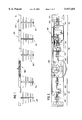
- FIG. 2 is a front plan view of the antenna assembly of FIG. 1;
- FIG. 3 is a front view of a phase adjustment mechanism in accordance with the present invention.
- FIG. 4 is a section view taken along section lines 4--4 of FIG. 3;
- FIG. 5 is a side view of the phase adjustment mechanism of FIG. 3;
- FIGS. 6a and 6b depict front and rear log-periodic dipole array sections
- FIG. 7 is a side view of the dipole array sections of FIGS. 6a and 6b in confronting relationship;
- FIG. 8a is a side view of an antenna assembly in accordance with the present invention with a radome in place;
- FIG. 8b is an end view of the antenna assembly of FIG. 8a;
- FIG. 9 is a plan view of a dielectric-substrated microstrip transformer
- FIG. 10 is a vertical radiation pattern of the antenna assembly in accordance with the present invention.
- FIG. 11 is a schematic representation of the antenna assembly of FIG. 1;
- FIG. 12 is a further vertical radiation pattern of the antenna assembly of FIG. 1;
- FIG. 13 is another vertical radiation pattern of the antenna assembly of FIG. 1;
- FIG. 14 is a schematic representation of a control system for use with the antenna assembly of FIG. 1;
- FIG. 15 depicts a plurality of antenna assemblies of FIG. 1 disposed on an antenna support structure
- FIG. 16 is a top view of FIG. 15.
- an electrically variable beam tilt antenna is described that provides distinct advantages when compared to systems of the prior art.
- the invention can best be understood with reference to the accompanying drawing figures.
- FIGS. 1 and 2 are side and front views, respectively, of an antenna assembly 100 in accordance with the present invention.
- the antenna assembly 100 comprises a plurality of antenna means such as antennas 101-105 arranged as first, second, and third antenna groups 115, 116, and 117.
- Antenna 101 alone forms the first antenna group 115, while antennas 102 and 103 form the second antenna group 116, and antennas 104 and 105 form the third antenna group 117.
- Phase adjustment means such as a phase adjustment mechanism 108, is disposed between the second and third antenna groups 116, 117. Operation and effect of the phase adjustment mechanism 108 will be discussed in detail subsequently.
- each of the antennas 101-105 is mounted along the longitudinal axis 110 of a conductive backplane 111.
- the conductive backplane is an aluminum extrusion, although any conductive plate of sufficient strength to provide support for the antennas 101-105 would serve.
- the material selected should be relatively light in weight, however, so that the completed antenna assembly will not be unwieldy.
- the backplane 111 also provides a mounting surface for an RF connector 109, the phase adjustment mechanism 108, and a plurality of dielectric-substrated microstrip transformers 112-114 used as power dividers, and the transmission lines that interconnect the antenna assembly components (1105-1110 in FIG. 11). These elements will be discussed in more detail below.
- the antenna assembly 100 includes five individual, log-periodic dipole array (LPDA) antennas 101-105, the design of which is generally well-known in the art.
- the particular configuration used in the preferred embodiment of the invention is illustrated in FIGS. 6a, 6b, and 7.
- the LPDA antennas 101-105 are formed from two confronting conductive sections 201, 202.
- the sections are generally complementary in shape, with the shorter front section 201 having one arm 203A of a particular dipole antenna, and the somewhat taller rear section 202 having the other arm 203B of the same dipole.
- the two sections 201, 202 are mounted in confronting relationship, with the upper portions of each section bent over at a 9 degree angle. This allows a coaxial cable 701 to be connected to the appropriate elements of the completed LPDA.
- the shield 702 is soldered to the front section 201, while the center conductor of the coaxial cable 701 is soldered to the rear section 202.
- FIGS. 8a and 8b illustrate an antenna assembly 100 of the present invention with a protective radome 801 attached.
- the radome 801 may be of plastic or fiberglass construction, for example.
- the phase adjustment mechanism 108 includes input coupling means such as an input coupling element 301 formed in a T-shape from a plate of conductive material.
- input coupling element 301 is formed from a sheet of 0.062 inch half-hard brass.
- the input coupling element 301 is electromagnetically coupled to movable coupling means, such as a movable coupling section 302, which is fixed near a first end to a pivot point 303.
- the movable coupling section 302 is also preferably formed from a sheet of 0.062 inch half-hard brass.
- the second end of the movable coupling section 302 terminates in a conductive plate 304 that is electromagnetically coupled to transmission line means, such as a semicircular, air-substrated transmission line section 305.
- the conductive plate 304 is an integrally formed part of the movable coupling section 302.
- the semicircular transmission line section 305 which is also preferably formed from 0.062 inch half-hard brass sheet stock, has first and second opposed end portions 306, 307 from which antenna feeder cables (1109, 1110 in FIG. 11) direct RF signals, having a desired phase relationship, to the first and third antenna groups 115, 117 of the antenna assembly 100.
- the second antenna group 116 is fed from a transformer 113 that divides the antenna input signal between the input coupling element 1101 of the phase adjustment mechanism 108 and the second antenna group 116.
- Ground connection brackets 308, 309 are provided near the respective opposed end portions 306, 307 for attachment of the shield portions of the antenna feeder cables.
- a similar ground bracket 310 is provided near the input coupling element 301 for attachment of the shield of an antenna assembly cable (1102 in FIG. 11).
- a first antenna feeder cable (1109 in FIG. 11) couples RF signals to the first antenna group 115. Since there is only one antenna 101 in this group in the preferred embodiment, no transformer or power divider is necessary.
- a power divider 113 divides input power between the input coupling element 1101 of the phase adjustment mechanism and a power divider 114 that feed the second antenna group 116.
- a third power divider 112 has two outputs; one for each of the antennas 104, 105 in the third antenna group 117.
- Each of the antennas 101-105 has a fifty ohm input impedance.
- An antenna output cable (1105-1108 in FIG. 11) couples RF power to each of the antennas 102-105).
- Power divider 112 illustrated in FIG. 9, is a dielectric-substrated microstrip transformer, formed by etching unwanted copper from a copper coated substrate 901 of low-loss dielectric material to leave microstrip transmission line sections 902 terminated in contact pads 903 to accommodate coaxial transmission lines.
- the vertical radiation pattern 1000 illustrated in FIG. 10, has a main lobe 1001 with a main lobe axis coincident with the 0 degree reference line.
- the illustrated pattern 1000 has a downtilt angle of 0 degrees because that is the angle that the main lobe axis makes with the 0 degree reference line.
- the radiation pattern 1000 can be tilted down with respect to the earth's surface (the 0 degree reference line) by feeding the individual antennas 101-105 slightly out of phase with one another.
- the phase shift is ordinarily made progressive.
- one of the antennas or antenna groups in the antenna assembly 100 (the first antenna group 115, in the preferred embodiment) is chosen as the reference group for phase purposes.
- the RF signal applied to the next antenna 102 is then phase shifted by some amount X with respect to the reference antenna 101.
- the RF signal applied to the third antenna 103 is phase shifted by X degrees with respect to the second antenna 102 (2X degrees with respect to the first antenna 101). This progressive phase shift is continued for all of the antennas 101-105 in the antenna assembly 100.
- the progressive phase shift is approximately equal to one inch (each of the transmission paths to the individual antennas differs in electrical length, at the design operating frequency, by one inch, resulting in a phase shift of about 30 degrees at the operating frequency) and the vertical pattern tilts down five degrees.
- FIG. 11 illustrates schematically the way in which the progressive phase shift is implemented with the phase adjustment mechanism 108 set at mid-range 1101.
- an antenna feeder cable 1109 couples a first end of the semicircular, air-substrated transmission line section 305 of the phase adjustment mechanism 108 to a first antenna group 115, which comprises a single antenna 101 in the preferred embodiment.
- the overall electrical path length, measured from the output of power divider 113, where the input signal splits, to the point where the antenna cable 1109 couples to the first antenna 101, is approximately 20 inches, with the phase adjustment mechanism 305 at its mid-point 1101. This means, of course, that approximately one-half of the semicircular, air-substrated transmission line section 305 is included in the electrical path length for antennas of the first antenna group 115 and antennas of the third antenna group 117.
- the overall electrical path length from the divider 113 output point to the second antenna 102 is 21 inches, to the third antenna 103 is 22 inches, to the fourth antenna 104 is 23 inches, and to the fifth antenna 105 is 24 inches, all with the phase adjustment mechanism 108 set at its mid-point 1101.
- phase adjustment mechanism 108 set at its mid-point 1101
- a true progressive phase shift of approximately 30 degrees has been established between the antennas 101-105 of the antenna assembly.
- the phase adjustment mechanism 108 set at this mid-point 1101 position, the radiation pattern of the antenna exhibits a 5 degree downtilt as illustrated in FIG. 12.
- FIG. 12 shows the vertical radiation pattern 1200 of the antenna assembly 100 with the phase adjustment mechanism set at its mid-point 1101.
- the axis 1202 of the main lobe 1201 is now coincident with the -7 degree reference line, indicating that the main lobe axis is now tilted down 7 degrees with respect to the earth's surface.
- the effective electrical path length to the first antenna group 101 is now about 18 inches, to the fourth antenna 104 about 25 inches, and to the fifth antenna 105 about 26 inches.
- phase adjustment mechanism set at its minimum downtilt position 1113, at least some of the phase relationships among the antennas of the first and second antenna groups 106, 107 are effectively reversed.
- the electrical path length to the first antenna 101 is now lengthened to 22 inches.
- the electrical path length to the fourth antenna is about 21 inches, and the path to the fifth antenna is about 22 inches.
- the effect on the vertical radiation pattern of the antenna assembly 100 with the phase adjustment mechanism 108 set at this minimum downtilt position 1113 is to restore the downtilt angle to zero degrees, as illustrated in FIG. 10.
- FIG. 14 depicts a remote control configuration for vertical radiation pattern downtilt adjustment.
- drive means such as a drive mechanism 1401 is provided, mechanically connected to the movable coupling element of the phase adjustment mechanism 108.
- the drive mechanism may be an electric motor, a resolver or servomotor, a stepping motor, or any of a number of known positioning devices.
- Control inputs 1403 for the drive mechanism 1401 may be provided from a remote location, such as a maintenance facility of the local service provider.
- Position information 1404 is provided to the remote location by a position detector 1402.
- the position detector may be implemented by Hall effect sensors, optical encoders, a synchro/servo system, or any of a number of other known position detection devices.
- FIGS. 15 and 16 illustrate a plurality of antenna assemblies 100 (three) in accordance with the present invention supported in normal operating position by an antenna support structure 1501, such as a tower.
- the antenna assemblies 100 are positioned such that the longitudinal axis of each antenna assembly 100 is substantially perpendicular to the earth's surface 1502.
- Each assembly 100 is designed to cover a 120 degree sector of a cell and is adapted to be adjusted as described above.
Abstract
Description
Claims (33)
Priority Applications (5)
| Application Number | Priority Date | Filing Date | Title |
|---|---|---|---|
| US08/747,627 US5917455A (en) | 1996-11-13 | 1996-11-13 | Electrically variable beam tilt antenna |
| PCT/US1997/020143 WO1998021779A1 (en) | 1996-11-13 | 1997-11-12 | Electrically variable beam tilt antenna |
| AU71820/98A AU7182098A (en) | 1996-11-13 | 1997-11-12 | Electrically variable beam tilt antenna |
| TW086116909A TW382834B (en) | 1996-11-13 | 1997-11-13 | Electrically variable beam tilt antenna |
| US10/747,818 USRE44332E1 (en) | 1996-11-13 | 2003-12-29 | Electrically variable beam tilt antenna |
Applications Claiming Priority (1)
| Application Number | Priority Date | Filing Date | Title |
|---|---|---|---|
| US08/747,627 US5917455A (en) | 1996-11-13 | 1996-11-13 | Electrically variable beam tilt antenna |
Related Child Applications (1)
| Application Number | Title | Priority Date | Filing Date |
|---|---|---|---|
| US10/747,818 Reissue USRE44332E1 (en) | 1996-11-13 | 2003-12-29 | Electrically variable beam tilt antenna |
Publications (1)
| Publication Number | Publication Date |
|---|---|
| US5917455A true US5917455A (en) | 1999-06-29 |
Family
ID=25005941
Family Applications (2)
| Application Number | Title | Priority Date | Filing Date |
|---|---|---|---|
| US08/747,627 Ceased US5917455A (en) | 1996-11-13 | 1996-11-13 | Electrically variable beam tilt antenna |
| US10/747,818 Expired - Lifetime USRE44332E1 (en) | 1996-11-13 | 2003-12-29 | Electrically variable beam tilt antenna |
Family Applications After (1)
| Application Number | Title | Priority Date | Filing Date |
|---|---|---|---|
| US10/747,818 Expired - Lifetime USRE44332E1 (en) | 1996-11-13 | 2003-12-29 | Electrically variable beam tilt antenna |
Country Status (4)
| Country | Link |
|---|---|
| US (2) | US5917455A (en) |
| AU (1) | AU7182098A (en) |
| TW (1) | TW382834B (en) |
| WO (1) | WO1998021779A1 (en) |
Cited By (49)
| Publication number | Priority date | Publication date | Assignee | Title |
|---|---|---|---|---|
| WO2001024312A1 (en) * | 1999-09-29 | 2001-04-05 | Radio Frequency Systems, Inc. | Mechanically adjustable phase-shifting parasitic antenna element |
| WO2002007254A1 (en) * | 2000-07-18 | 2002-01-24 | Kathrein-Werke Kg | Antenna for multi-frequency operation |
| US6366237B1 (en) * | 1999-02-24 | 2002-04-02 | France Telecom | Adjustable-tilt antenna |
| US6377217B1 (en) | 1999-09-14 | 2002-04-23 | Paratek Microwave, Inc. | Serially-fed phased array antennas with dielectric phase shifters |
| US6407677B1 (en) * | 1998-12-21 | 2002-06-18 | Valeo Securite Habitacle | Device for low-frequency communication by magnetic coupling |
| KR100374175B1 (en) * | 2000-12-29 | 2003-03-03 | 주식회사 에이스테크놀로지 | A variable down-tilting array antenna |
| US6529171B1 (en) * | 1999-05-10 | 2003-03-04 | Alcatel | Vertical polarization antenna |
| US6538603B1 (en) | 2000-07-21 | 2003-03-25 | Paratek Microwave, Inc. | Phased array antennas incorporating voltage-tunable phase shifters |
| US20030076198A1 (en) * | 2001-08-23 | 2003-04-24 | Ems Technologies, Inc. | Microstrip phase shifter |
| WO2003034547A1 (en) * | 2001-10-11 | 2003-04-24 | Kathrein-Werke Kg | Dual-polarization antenna array |
| US6573875B2 (en) * | 2001-02-19 | 2003-06-03 | Andrew Corporation | Antenna system |
| US20030109231A1 (en) * | 2001-02-01 | 2003-06-12 | Hurler Marcus | Control device for adjusting a different slope angle, especially of a mobile radio antenna associated with a base station, and corresponding antenna and corresponding method for modifying the slope angle |
| US6621377B2 (en) | 2000-05-02 | 2003-09-16 | Paratek Microwave, Inc. | Microstrip phase shifter |
| US6646522B1 (en) | 1999-08-24 | 2003-11-11 | Paratek Microwave, Inc. | Voltage tunable coplanar waveguide phase shifters |
| US6667714B1 (en) * | 2000-05-03 | 2003-12-23 | Lucent Technologies Inc. | Downtilt control for multiple antenna arrays |
| US6724350B1 (en) * | 2000-06-28 | 2004-04-20 | Bellsouth Intellectual Property Corporation | Antenna system |
| US20040090286A1 (en) * | 2002-11-08 | 2004-05-13 | Ems Technologies, Inc. | Variable power divider |
| US20040145531A1 (en) * | 2002-03-29 | 2004-07-29 | Godard Jeffrey A. | Microstrip fed log periodic antenna |
| US20040203284A1 (en) * | 2003-04-11 | 2004-10-14 | Kathrein-Werke Kg. | Connecting device for connecting at least two antenna element devices, which are arranged offset with respect to one another, of an antenna arrangement |
| US20040209572A1 (en) * | 2001-10-22 | 2004-10-21 | Thomas Louis David | Antenna system |
| US20040252071A1 (en) * | 2002-03-26 | 2004-12-16 | Bisiules Peter John | Multiband dual polarized adjustable beamtilt base station antenna |
| US20040263410A1 (en) * | 2001-03-20 | 2004-12-30 | Allen Telecom Group, Inc. | Antenna array |
| US20050001778A1 (en) * | 2003-07-03 | 2005-01-06 | Kevin Le | Wideband dual polarized base station antenna offering optimized horizontal beam radiation patterns and variable vertical beam tilt |
| US20050017822A1 (en) * | 2002-11-08 | 2005-01-27 | Ems Technologies, Inc. | Variable power divider |
| US6850130B1 (en) * | 1999-08-17 | 2005-02-01 | Kathrein-Werke Kg | High-frequency phase shifter unit having pivotable tapping element |
| US20050046514A1 (en) * | 2003-08-28 | 2005-03-03 | Janoschka Darin M. | Wiper-type phase shifter with cantilever shoe and dual-polarization antenna with commonly driven phase shifters |
| US20050179610A1 (en) * | 2002-12-13 | 2005-08-18 | Kevin Le | Directed dipole antenna |
| US20050219133A1 (en) * | 2004-04-06 | 2005-10-06 | Elliot Robert D | Phase shifting network |
| US20060066494A1 (en) * | 2003-02-24 | 2006-03-30 | Zdenek Trejtnar | Radiocommunications antenna with misalignment of radiation lobe by variable phase shifter |
| US20060077098A1 (en) * | 2004-10-13 | 2006-04-13 | Andrew Corporation | Panel antenna with variable phase shifter |
| WO2006059230A1 (en) * | 2004-12-01 | 2006-06-08 | Finglas Technologies Limited | Antenna assembly |
| US20060202900A1 (en) * | 2005-03-08 | 2006-09-14 | Ems Technologies, Inc. | Capacitively coupled log periodic dipole antenna |
| US20070063911A1 (en) * | 2003-06-16 | 2007-03-22 | Davidson D | Cellular antenna and systems and methods therefor |
| US20070149250A1 (en) * | 2003-10-23 | 2007-06-28 | Telecom Italia S.P.A | Antenna system and method for configuring a radiating pattern |
| EP1815557A1 (en) * | 2004-11-26 | 2007-08-08 | Powerwave Technologies Sweden AB | Antenna control system |
| US20080211600A1 (en) * | 2005-03-22 | 2008-09-04 | Radiaciony Microondas S.A. | Broad Band Mechanical Phase Shifter |
| US7429960B2 (en) * | 2006-04-27 | 2008-09-30 | Agc Automotive Americas R & D, Inc. | Log-periodic antenna |
| US20080252522A1 (en) * | 2007-04-13 | 2008-10-16 | Asbridge Harold E | Array antenna and a method of determining an antenna beam attribute |
| US20090061941A1 (en) * | 2006-03-17 | 2009-03-05 | Steve Clark | Telecommunications antenna monitoring system |
| US20100053008A1 (en) * | 2008-08-27 | 2010-03-04 | Pc-Tel, Inc. | Antenna having distributed phase shift mechanism |
| WO2010124787A1 (en) | 2009-04-30 | 2010-11-04 | Kathrein-Werke Kg | Method for operating a phase-controlled group antenna and a phase shifter assembly and an associated phase-controlled group antenna |
| US20110199992A1 (en) * | 2010-01-19 | 2011-08-18 | David Edwin Barker | Method and apparatus for antenna radiation pattern sweeping |
| US20110241954A1 (en) * | 2010-03-31 | 2011-10-06 | Le Quoc M | Rf tilt sensing using mems accelerometers |
| JP2012526447A (en) * | 2009-05-11 | 2012-10-25 | ケーエムダブリュ・インコーポレーテッド | Multi-line phase shifter for vertical beam tilt control antenna |
| JP2013021495A (en) * | 2011-07-11 | 2013-01-31 | Sumitomo Electric Ind Ltd | Antenna system for broadcast |
| US20160301141A1 (en) * | 2013-05-01 | 2016-10-13 | Byron del Castillo | Radio Communication System With Antenna Array |
| CN107579330A (en) * | 2017-08-31 | 2018-01-12 | 华桂星 | A kind of antenna assembly and its apply the signal coverage method in elevator hoistways |
| US10170831B2 (en) * | 2015-08-25 | 2019-01-01 | Elwha Llc | Systems, methods and devices for mechanically producing patterns of electromagnetic energy |
| US10177456B2 (en) * | 2014-07-31 | 2019-01-08 | Commissariat A L'energie Atomique Et Aux Energies Alternatives | Log-periodic antenna with wide frequency band |
Families Citing this family (8)
| Publication number | Priority date | Publication date | Assignee | Title |
|---|---|---|---|---|
| WO2006024516A1 (en) | 2004-08-31 | 2006-03-09 | Fractus, S.A. | Slim multi-band antenna array for cellular base stations |
| WO2006130083A1 (en) | 2005-05-31 | 2006-12-07 | Powerwave Technologies Sweden Ab | Beam adjusting device |
| CN2812316Y (en) * | 2005-06-02 | 2006-08-30 | 京信通信技术(广州)有限公司 | Adjuster for mobile communication antenna phase shifter |
| FI20055285A (en) | 2005-06-03 | 2006-12-04 | Filtronic Comtek Oy | Arrangements for controlling a base station antenna |
| EP1935057B1 (en) | 2005-10-14 | 2012-02-01 | Fractus S.A. | Slim triple band antenna array for cellular base stations |
| US20100060522A1 (en) * | 2006-12-22 | 2010-03-11 | Telefonaktiebolaget Lm Ericsson (Publ) | Antenna Arrangement |
| CN111883929B (en) * | 2020-05-28 | 2022-07-05 | 上海民航华东空管工程技术有限公司 | Debugging method for reducing downward sliding angle of M-type downward sliding antenna |
| CN115632228B (en) * | 2022-09-29 | 2023-09-29 | 湖南迈克森伟电子科技有限公司 | Antenna unit, antenna array and electronic equipment |
Citations (8)
| Publication number | Priority date | Publication date | Assignee | Title |
|---|---|---|---|---|
| US3110030A (en) * | 1961-05-25 | 1963-11-05 | Martin Marietta Corp | Cone mounted logarithmic dipole array antenna |
| US3193831A (en) * | 1961-11-22 | 1965-07-06 | Andrew Corp | Logarithmic periodic antenna |
| US4203118A (en) * | 1978-04-10 | 1980-05-13 | Andrew Alford | Antenna for cross polarized waves |
| JPS636906A (en) * | 1986-06-27 | 1988-01-12 | Toshiba Corp | Variable directional array antenna system |
| US4788515A (en) * | 1988-02-19 | 1988-11-29 | Hughes Aircraft Company | Dielectric loaded adjustable phase shifting apparatus |
| US5187455A (en) * | 1990-06-13 | 1993-02-16 | Murata Manufacturing Co., Ltd. | Delay line device with adjustable time delay |
| US5281974A (en) * | 1988-01-11 | 1994-01-25 | Nec Corporation | Antenna device capable of reducing a phase noise |
| US5617103A (en) * | 1995-07-19 | 1997-04-01 | The United States Of America As Represented By The Secretary Of The Army | Ferroelectric phase shifting antenna array |
Family Cites Families (18)
| Publication number | Priority date | Publication date | Assignee | Title |
|---|---|---|---|---|
| US2968808A (en) | 1954-08-24 | 1961-01-17 | Alford Andrew | Steerable antenna array |
| US4241352A (en) | 1976-09-15 | 1980-12-23 | Ball Brothers Research Corporation | Feed network scanning antenna employing rotating directional coupler |
| GB1599654A (en) * | 1977-08-05 | 1981-10-07 | Holman R R | Automatic lancet |
| JP2569868B2 (en) | 1990-02-26 | 1997-01-08 | 三菱電機株式会社 | Antenna device |
| NZ235010A (en) | 1990-08-22 | 1993-12-23 | Deltec New Zealand | Dipole panel antenna with electrically tiltable beam. |
| JP2949533B2 (en) | 1991-09-03 | 1999-09-13 | 日本電信電話株式会社 | Mobile communication wireless zone configuration method |
| JP3120497B2 (en) | 1991-10-25 | 2000-12-25 | 住友電気工業株式会社 | Distribution phase shifter |
| US5805996A (en) | 1991-12-13 | 1998-09-08 | Nokia Telecommunications Oy | Base station with antenna coverage directed into neighboring cells based on traffic load |
| CA2097122A1 (en) | 1992-06-08 | 1993-12-09 | James Hadzoglou | Adjustable beam tilt antenna |
| AU664625B2 (en) | 1992-07-17 | 1995-11-23 | Radio Frequency Systems Pty Limited | Phase shifter |
| US5488737A (en) | 1992-11-17 | 1996-01-30 | Southwestern Bell Technology Resources, Inc. | Land-based wireless communications system having a scanned directional antenna |
| JPH06326501A (en) | 1993-05-12 | 1994-11-25 | Sumitomo Electric Ind Ltd | Distribution variable phase shifter |
| CN1072849C (en) | 1993-10-14 | 2001-10-10 | 黛尔泰克国际电信体系有限公司 | Variable differential phase shifter |
| US5818385A (en) | 1994-06-10 | 1998-10-06 | Bartholomew; Darin E. | Antenna system and method |
| JP2993551B2 (en) | 1994-08-01 | 1999-12-20 | エヌ・ティ・ティ移動通信網株式会社 | Zone change system in mobile communication |
| CN1094260C (en) | 1994-11-04 | 2002-11-13 | 安德鲁公司 | Antenna control system |
| US6573875B2 (en) * | 2001-02-19 | 2003-06-03 | Andrew Corporation | Antenna system |
| JP5121915B2 (en) | 2010-12-07 | 2013-01-16 | 中国電力株式会社 | Method and apparatus for treating jellyfish at water intake of power plant |
-
1996
- 1996-11-13 US US08/747,627 patent/US5917455A/en not_active Ceased
-
1997
- 1997-11-12 AU AU71820/98A patent/AU7182098A/en not_active Abandoned
- 1997-11-12 WO PCT/US1997/020143 patent/WO1998021779A1/en active Application Filing
- 1997-11-13 TW TW086116909A patent/TW382834B/en not_active IP Right Cessation
-
2003
- 2003-12-29 US US10/747,818 patent/USRE44332E1/en not_active Expired - Lifetime
Patent Citations (8)
| Publication number | Priority date | Publication date | Assignee | Title |
|---|---|---|---|---|
| US3110030A (en) * | 1961-05-25 | 1963-11-05 | Martin Marietta Corp | Cone mounted logarithmic dipole array antenna |
| US3193831A (en) * | 1961-11-22 | 1965-07-06 | Andrew Corp | Logarithmic periodic antenna |
| US4203118A (en) * | 1978-04-10 | 1980-05-13 | Andrew Alford | Antenna for cross polarized waves |
| JPS636906A (en) * | 1986-06-27 | 1988-01-12 | Toshiba Corp | Variable directional array antenna system |
| US5281974A (en) * | 1988-01-11 | 1994-01-25 | Nec Corporation | Antenna device capable of reducing a phase noise |
| US4788515A (en) * | 1988-02-19 | 1988-11-29 | Hughes Aircraft Company | Dielectric loaded adjustable phase shifting apparatus |
| US5187455A (en) * | 1990-06-13 | 1993-02-16 | Murata Manufacturing Co., Ltd. | Delay line device with adjustable time delay |
| US5617103A (en) * | 1995-07-19 | 1997-04-01 | The United States Of America As Represented By The Secretary Of The Army | Ferroelectric phase shifting antenna array |
Cited By (95)
| Publication number | Priority date | Publication date | Assignee | Title |
|---|---|---|---|---|
| US6407677B1 (en) * | 1998-12-21 | 2002-06-18 | Valeo Securite Habitacle | Device for low-frequency communication by magnetic coupling |
| US6366237B1 (en) * | 1999-02-24 | 2002-04-02 | France Telecom | Adjustable-tilt antenna |
| US6529171B1 (en) * | 1999-05-10 | 2003-03-04 | Alcatel | Vertical polarization antenna |
| US6850130B1 (en) * | 1999-08-17 | 2005-02-01 | Kathrein-Werke Kg | High-frequency phase shifter unit having pivotable tapping element |
| US6954118B2 (en) | 1999-08-24 | 2005-10-11 | Paratek Microwave, Inc. | Voltage tunable coplanar phase shifters with a conductive dome structure |
| US6646522B1 (en) | 1999-08-24 | 2003-11-11 | Paratek Microwave, Inc. | Voltage tunable coplanar waveguide phase shifters |
| US20040036553A1 (en) * | 1999-08-24 | 2004-02-26 | Andrey Kozyrev | Voltage tunable coplanar phase shifters |
| US6377217B1 (en) | 1999-09-14 | 2002-04-23 | Paratek Microwave, Inc. | Serially-fed phased array antennas with dielectric phase shifters |
| AU770240B2 (en) * | 1999-09-29 | 2004-02-19 | Radio Frequency Systems Inc. | Mechanically adjustable phase-shifting parasitic antenna element |
| US6310585B1 (en) | 1999-09-29 | 2001-10-30 | Radio Frequency Systems, Inc. | Isolation improvement mechanism for dual polarization scanning antennas |
| WO2001024312A1 (en) * | 1999-09-29 | 2001-04-05 | Radio Frequency Systems, Inc. | Mechanically adjustable phase-shifting parasitic antenna element |
| US6621377B2 (en) | 2000-05-02 | 2003-09-16 | Paratek Microwave, Inc. | Microstrip phase shifter |
| US6667714B1 (en) * | 2000-05-03 | 2003-12-23 | Lucent Technologies Inc. | Downtilt control for multiple antenna arrays |
| US6724350B1 (en) * | 2000-06-28 | 2004-04-20 | Bellsouth Intellectual Property Corporation | Antenna system |
| US7023400B2 (en) | 2000-06-28 | 2006-04-04 | Bellsouth Intellectual Property Corp. | Antenna system |
| US20040164921A1 (en) * | 2000-06-28 | 2004-08-26 | Hill David A. | Antenna system |
| WO2002007254A1 (en) * | 2000-07-18 | 2002-01-24 | Kathrein-Werke Kg | Antenna for multi-frequency operation |
| US6759980B2 (en) | 2000-07-21 | 2004-07-06 | Paratek Microwave, Inc. | Phased array antennas incorporating voltage-tunable phase shifters |
| US6756939B2 (en) | 2000-07-21 | 2004-06-29 | Paratek Microwave, Inc. | Phased array antennas incorporating voltage-tunable phase shifters |
| US6538603B1 (en) | 2000-07-21 | 2003-03-25 | Paratek Microwave, Inc. | Phased array antennas incorporating voltage-tunable phase shifters |
| KR100374175B1 (en) * | 2000-12-29 | 2003-03-03 | 주식회사 에이스테크놀로지 | A variable down-tilting array antenna |
| US20030109231A1 (en) * | 2001-02-01 | 2003-06-12 | Hurler Marcus | Control device for adjusting a different slope angle, especially of a mobile radio antenna associated with a base station, and corresponding antenna and corresponding method for modifying the slope angle |
| US20050272470A1 (en) * | 2001-02-01 | 2005-12-08 | Kathrein Werke Kg | Control apparatus for changing a downtilt angle for antennas, in particular for a mobile radio antenna for a base station, as well as an associated mobile radio antenna and a method for changing the downtilt angle |
| CN1505850B (en) * | 2001-02-19 | 2010-05-26 | 安德鲁公司 | Cellular base station antenna |
| EP1362387A4 (en) * | 2001-02-19 | 2004-01-21 | Andrew Corp | Cellular base station antenna |
| US6987487B2 (en) | 2001-02-19 | 2006-01-17 | Andrew Corporation | Antenna system |
| US6573875B2 (en) * | 2001-02-19 | 2003-06-03 | Andrew Corporation | Antenna system |
| AU2002241955B2 (en) * | 2001-02-19 | 2008-01-10 | Andrew Llc | Cellular base station antenna |
| US7075497B2 (en) | 2001-03-20 | 2006-07-11 | Andrew Corporation | Antenna array |
| US20040263410A1 (en) * | 2001-03-20 | 2004-12-30 | Allen Telecom Group, Inc. | Antenna array |
| US20030076198A1 (en) * | 2001-08-23 | 2003-04-24 | Ems Technologies, Inc. | Microstrip phase shifter |
| US7233217B2 (en) * | 2001-08-23 | 2007-06-19 | Andrew Corporation | Microstrip phase shifter |
| US20040051677A1 (en) * | 2001-10-11 | 2004-03-18 | Goettl Maximilian | Dual-polarization antenna array |
| US6985123B2 (en) | 2001-10-11 | 2006-01-10 | Kathrein-Werke Kg | Dual-polarization antenna array |
| CN100574008C (en) * | 2001-10-11 | 2009-12-23 | 凯瑟雷恩工厂两合公司 | Dual-polarized antenna array |
| WO2003034547A1 (en) * | 2001-10-11 | 2003-04-24 | Kathrein-Werke Kg | Dual-polarization antenna array |
| US7365695B2 (en) * | 2001-10-22 | 2008-04-29 | Quintel Technology Limited | Antenna system |
| US20040209572A1 (en) * | 2001-10-22 | 2004-10-21 | Thomas Louis David | Antenna system |
| US7405710B2 (en) | 2002-03-26 | 2008-07-29 | Andrew Corporation | Multiband dual polarized adjustable beamtilt base station antenna |
| US20040252071A1 (en) * | 2002-03-26 | 2004-12-16 | Bisiules Peter John | Multiband dual polarized adjustable beamtilt base station antenna |
| US6885350B2 (en) | 2002-03-29 | 2005-04-26 | Arc Wireless Solutions, Inc. | Microstrip fed log periodic antenna |
| US20040145531A1 (en) * | 2002-03-29 | 2004-07-29 | Godard Jeffrey A. | Microstrip fed log periodic antenna |
| US20050017822A1 (en) * | 2002-11-08 | 2005-01-27 | Ems Technologies, Inc. | Variable power divider |
| US6788165B2 (en) | 2002-11-08 | 2004-09-07 | Ems Technologies, Inc. | Variable power divider |
| US20040090286A1 (en) * | 2002-11-08 | 2004-05-13 | Ems Technologies, Inc. | Variable power divider |
| US7221239B2 (en) | 2002-11-08 | 2007-05-22 | Andrew Corporation | Variable power divider |
| US7358922B2 (en) | 2002-12-13 | 2008-04-15 | Commscope, Inc. Of North Carolina | Directed dipole antenna |
| US20050179610A1 (en) * | 2002-12-13 | 2005-08-18 | Kevin Le | Directed dipole antenna |
| US20060066494A1 (en) * | 2003-02-24 | 2006-03-30 | Zdenek Trejtnar | Radiocommunications antenna with misalignment of radiation lobe by variable phase shifter |
| US7286092B2 (en) * | 2003-02-24 | 2007-10-23 | Jaybeam Limited | Radiocommunications antenna with misalignment of radiation lobe by variable phase shifter |
| US20040203284A1 (en) * | 2003-04-11 | 2004-10-14 | Kathrein-Werke Kg. | Connecting device for connecting at least two antenna element devices, which are arranged offset with respect to one another, of an antenna arrangement |
| US6949993B2 (en) * | 2003-04-11 | 2005-09-27 | Kathrein-Werke Kg | Connecting device for connecting at least two antenna element devices, which are arranged offset with respect to one another, of an antenna arrangement |
| US8018390B2 (en) | 2003-06-16 | 2011-09-13 | Andrew Llc | Cellular antenna and systems and methods therefor |
| US20070063911A1 (en) * | 2003-06-16 | 2007-03-22 | Davidson D | Cellular antenna and systems and methods therefor |
| US20050001778A1 (en) * | 2003-07-03 | 2005-01-06 | Kevin Le | Wideband dual polarized base station antenna offering optimized horizontal beam radiation patterns and variable vertical beam tilt |
| CN1833337B (en) * | 2003-07-03 | 2012-10-31 | 安德鲁公司 | Wideband dual polarized base station antenna offering optimized horizontal beam radiation patterns and variable vertical beam tilt |
| DE112004001506B4 (en) * | 2003-07-03 | 2014-03-20 | Andrew Corp. | Broadband, dual polarized base station antenna for optimal horizontal radiation pattern and variable vertical beam tilt |
| WO2005062428A1 (en) * | 2003-07-03 | 2005-07-07 | Andrew Corporation | Wideband dual polarized base station antenna offering optimized horizontal beam radiation patterns and variable vertical beam tilt |
| US6924776B2 (en) | 2003-07-03 | 2005-08-02 | Andrew Corporation | Wideband dual polarized base station antenna offering optimized horizontal beam radiation patterns and variable vertical beam tilt |
| US20050046514A1 (en) * | 2003-08-28 | 2005-03-03 | Janoschka Darin M. | Wiper-type phase shifter with cantilever shoe and dual-polarization antenna with commonly driven phase shifters |
| US7170466B2 (en) | 2003-08-28 | 2007-01-30 | Ems Technologies, Inc. | Wiper-type phase shifter with cantilever shoe and dual-polarization antenna with commonly driven phase shifters |
| US7835768B2 (en) | 2003-10-23 | 2010-11-16 | Telecom Itala S.p.A. | Antenna system and method for configuring a radiating pattern |
| US20070149250A1 (en) * | 2003-10-23 | 2007-06-28 | Telecom Italia S.P.A | Antenna system and method for configuring a radiating pattern |
| US20050219133A1 (en) * | 2004-04-06 | 2005-10-06 | Elliot Robert D | Phase shifting network |
| US20060077098A1 (en) * | 2004-10-13 | 2006-04-13 | Andrew Corporation | Panel antenna with variable phase shifter |
| US7298233B2 (en) * | 2004-10-13 | 2007-11-20 | Andrew Corporation | Panel antenna with variable phase shifter |
| US7463190B2 (en) | 2004-10-13 | 2008-12-09 | Andrew Llc | Panel antenna with variable phase shifter |
| US20080024385A1 (en) * | 2004-10-13 | 2008-01-31 | Andrew Corporation | Panel Antenna with Variable Phase Shifter |
| EP1815557A1 (en) * | 2004-11-26 | 2007-08-08 | Powerwave Technologies Sweden AB | Antenna control system |
| EP1815557A4 (en) * | 2004-11-26 | 2010-04-21 | Powerwave Technologies Sweden | Antenna control system |
| US20070001919A1 (en) * | 2004-12-01 | 2007-01-04 | Carroll Niallo D | Antenna assembly |
| WO2006059230A1 (en) * | 2004-12-01 | 2006-06-08 | Finglas Technologies Limited | Antenna assembly |
| US7782268B2 (en) | 2004-12-01 | 2010-08-24 | Kavveri Telecom Products Limited | Antenna assembly |
| US20060202900A1 (en) * | 2005-03-08 | 2006-09-14 | Ems Technologies, Inc. | Capacitively coupled log periodic dipole antenna |
| US20080211600A1 (en) * | 2005-03-22 | 2008-09-04 | Radiaciony Microondas S.A. | Broad Band Mechanical Phase Shifter |
| US7557675B2 (en) * | 2005-03-22 | 2009-07-07 | Radiacion Y Microondas, S.A. | Broad band mechanical phase shifter |
| US20090061941A1 (en) * | 2006-03-17 | 2009-03-05 | Steve Clark | Telecommunications antenna monitoring system |
| US7429960B2 (en) * | 2006-04-27 | 2008-09-30 | Agc Automotive Americas R & D, Inc. | Log-periodic antenna |
| US7830307B2 (en) | 2007-04-13 | 2010-11-09 | Andrew Llc | Array antenna and a method of determining an antenna beam attribute |
| US20080252522A1 (en) * | 2007-04-13 | 2008-10-16 | Asbridge Harold E | Array antenna and a method of determining an antenna beam attribute |
| US20100053008A1 (en) * | 2008-08-27 | 2010-03-04 | Pc-Tel, Inc. | Antenna having distributed phase shift mechanism |
| WO2010124787A1 (en) | 2009-04-30 | 2010-11-04 | Kathrein-Werke Kg | Method for operating a phase-controlled group antenna and a phase shifter assembly and an associated phase-controlled group antenna |
| DE102009019557A1 (en) | 2009-04-30 | 2010-11-11 | Kathrein-Werke Kg | A method of operating a phased array antenna and a phase shifter assembly and associated phased array antenna |
| US9160062B2 (en) | 2009-04-30 | 2015-10-13 | Kathrein-Werke Kg | Method for operating a phase-controlled group antenna and phase shifter assembly and an associated phase-controlled group antenna |
| JP2012526447A (en) * | 2009-05-11 | 2012-10-25 | ケーエムダブリュ・インコーポレーテッド | Multi-line phase shifter for vertical beam tilt control antenna |
| US8907744B2 (en) | 2009-05-11 | 2014-12-09 | Kmw Inc. | Multi-line phase shifter having a fixed plate and a mobile plate in slideable engagement to provide vertical beam-tilt |
| US9190715B2 (en) * | 2010-01-19 | 2015-11-17 | Quintel Technology Limited | Method and apparatus for antenna radiation pattern sweeping |
| US20110199992A1 (en) * | 2010-01-19 | 2011-08-18 | David Edwin Barker | Method and apparatus for antenna radiation pattern sweeping |
| US8674788B2 (en) * | 2010-03-31 | 2014-03-18 | Andrew Llc | Phase shifter having an accelerometer disposed on a movable circuit board |
| US20110241954A1 (en) * | 2010-03-31 | 2011-10-06 | Le Quoc M | Rf tilt sensing using mems accelerometers |
| JP2013021495A (en) * | 2011-07-11 | 2013-01-31 | Sumitomo Electric Ind Ltd | Antenna system for broadcast |
| US20160301141A1 (en) * | 2013-05-01 | 2016-10-13 | Byron del Castillo | Radio Communication System With Antenna Array |
| US10177456B2 (en) * | 2014-07-31 | 2019-01-08 | Commissariat A L'energie Atomique Et Aux Energies Alternatives | Log-periodic antenna with wide frequency band |
| US10170831B2 (en) * | 2015-08-25 | 2019-01-01 | Elwha Llc | Systems, methods and devices for mechanically producing patterns of electromagnetic energy |
| CN107579330A (en) * | 2017-08-31 | 2018-01-12 | 华桂星 | A kind of antenna assembly and its apply the signal coverage method in elevator hoistways |
Also Published As
| Publication number | Publication date |
|---|---|
| WO1998021779A1 (en) | 1998-05-22 |
| USRE44332E1 (en) | 2013-07-02 |
| AU7182098A (en) | 1998-06-03 |
| TW382834B (en) | 2000-02-21 |
Similar Documents
| Publication | Publication Date | Title |
|---|---|---|
| US5917455A (en) | Electrically variable beam tilt antenna | |
| US5629713A (en) | Horizontally polarized antenna array having extended E-plane beam width and method for accomplishing beam width extension | |
| CN106450690B (en) | Low profile overlay antenna | |
| EP1751821B1 (en) | Directive dipole antenna | |
| US7365698B2 (en) | Dipole antenna | |
| US6963314B2 (en) | Dynamically variable beamwidth and variable azimuth scanning antenna | |
| US7196674B2 (en) | Dual polarized three-sector base station antenna with variable beam tilt | |
| JP3302442B2 (en) | Adjustable beam tilt antenna | |
| AU770240B2 (en) | Mechanically adjustable phase-shifting parasitic antenna element | |
| EP0976171B1 (en) | A method for improving antenna performance parameters and an antenna arrangement | |
| US6037912A (en) | Low profile bi-directional antenna | |
| CN1169387C (en) | Collapsible dipole antenna | |
| US6563399B2 (en) | Adjustable azimuth and phase shift antenna | |
| EP0691703B1 (en) | Communications antenna structure | |
| EP0618637B1 (en) | Antenna structure | |
| US20220247067A1 (en) | Base station antenna | |
| US6175340B1 (en) | Hybrid geostationary and low earth orbit satellite ground station antenna | |
| WO2021003081A1 (en) | Base station antenna including fabrey-perot cavities | |
| JPH07336133A (en) | Antenna device | |
| EP0805515A2 (en) | Antenna cross-polar suppression means | |
| US6930647B2 (en) | Semicircular radial antenna | |
| KR20140108412A (en) | Antenna phase shifting device and antenna having the same | |
| US5877729A (en) | Wide-beam high gain base station communications antenna | |
| KR19990014810A (en) | Antenna device with two radiating elements that can adjust the phase difference between radiating elements | |
| CN117810697A (en) | Phase shifter, base station antenna and base station |
Legal Events
| Date | Code | Title | Description |
|---|---|---|---|
| AS | Assignment |
Owner name: ALLEN TELECOM GROUP, INC., OHIO Free format text: ASSIGNMENT OF ASSIGNORS INTEREST;ASSIGNORS:HUYNH, TAN D.;MAILANDT, PETER;REEL/FRAME:008304/0931 Effective date: 19961112 |
|
| AS | Assignment |
Owner name: ALLEN TELECOM, INC., OHIO Free format text: MERGER AND CHANGE OF NAME;ASSIGNOR:ALLEN TELECOM GROUP, INC. A DELAWARE CORPORATION;REEL/FRAME:008400/0477 Effective date: 19970218 |
|
| STCF | Information on status: patent grant |
Free format text: PATENTED CASE |
|
| FPAY | Fee payment |
Year of fee payment: 4 |
|
| AS | Assignment |
Owner name: ADIRONDACKS LLC, ILLINOIS Free format text: ASSIGNMENT OF ASSIGNORS INTEREST;ASSIGNOR:ALLEN TELECOM, INC.;REEL/FRAME:014815/0914 Effective date: 20031216 |
|
| AS | Assignment |
Owner name: ANDREW CORPORATION, ILLINOIS Free format text: ASSIGNMENT OF ASSIGNORS INTEREST;ASSIGNOR:ALLEN TELECOM, LLC (FORMERLY ADIRONDACKS LLC);REEL/FRAME:014815/0332 Effective date: 20031204 |
|
| AS | Assignment |
Owner name: ALLEN TELECOM LLC, ILLINOIS Free format text: MERGER & CHANGE OF NAME;ASSIGNOR:ADIRONDACKS, LLC;REEL/FRAME:014830/0982 Effective date: 20030715 |
|
| RF | Reissue application filed |
Effective date: 20031229 |
|
| CC | Certificate of correction | ||
| FPAY | Fee payment |
Year of fee payment: 8 |
|
| AS | Assignment |
Owner name: BANK OF AMERICA, N.A., AS ADMINISTRATIVE AGENT, CA Free format text: SECURITY AGREEMENT;ASSIGNORS:COMMSCOPE, INC. OF NORTH CAROLINA;ALLEN TELECOM, LLC;ANDREW CORPORATION;REEL/FRAME:020362/0241 Effective date: 20071227 Owner name: BANK OF AMERICA, N.A., AS ADMINISTRATIVE AGENT,CAL Free format text: SECURITY AGREEMENT;ASSIGNORS:COMMSCOPE, INC. OF NORTH CAROLINA;ALLEN TELECOM, LLC;ANDREW CORPORATION;REEL/FRAME:020362/0241 Effective date: 20071227 |
|
| AS | Assignment |
Owner name: ANDREW LLC, NORTH CAROLINA Free format text: CHANGE OF NAME;ASSIGNOR:ANDREW CORPORATION;REEL/FRAME:021805/0276 Effective date: 20080827 |
|
| FPAY | Fee payment |
Year of fee payment: 12 |
|
| AS | Assignment |
Owner name: ANDREW LLC (F/K/A ANDREW CORPORATION), NORTH CAROL Free format text: PATENT RELEASE;ASSIGNOR:BANK OF AMERICA, N.A., AS ADMINISTRATIVE AGENT;REEL/FRAME:026039/0005 Effective date: 20110114 Owner name: COMMSCOPE, INC. OF NORTH CAROLINA, NORTH CAROLINA Free format text: PATENT RELEASE;ASSIGNOR:BANK OF AMERICA, N.A., AS ADMINISTRATIVE AGENT;REEL/FRAME:026039/0005 Effective date: 20110114 Owner name: ALLEN TELECOM LLC, NORTH CAROLINA Free format text: PATENT RELEASE;ASSIGNOR:BANK OF AMERICA, N.A., AS ADMINISTRATIVE AGENT;REEL/FRAME:026039/0005 Effective date: 20110114 |
|
| CC | Certificate of correction | ||
| AS | Assignment |
Owner name: JPMORGAN CHASE BANK, N.A., AS COLLATERAL AGENT, NE Free format text: SECURITY AGREEMENT;ASSIGNORS:ALLEN TELECOM LLC, A DELAWARE LLC;ANDREW LLC, A DELAWARE LLC;COMMSCOPE, INC. OF NORTH CAROLINA, A NORTH CAROLINA CORPORATION;REEL/FRAME:026276/0363 Effective date: 20110114 |
|
| AS | Assignment |
Owner name: JPMORGAN CHASE BANK, N.A., AS COLLATERAL AGENT, NE Free format text: SECURITY AGREEMENT;ASSIGNORS:ALLEN TELECOM LLC, A DELAWARE LLC;ANDREW LLC, A DELAWARE LLC;COMMSCOPE, INC OF NORTH CAROLINA, A NORTH CAROLINA CORPORATION;REEL/FRAME:026272/0543 Effective date: 20110114 |
|
| AS | Assignment |
Owner name: WILMINGTON TRUST, NATIONAL ASSOCIATION, AS COLLATERAL AGENT, CONNECTICUT Free format text: SECURITY INTEREST;ASSIGNORS:ALLEN TELECOM LLC;COMMSCOPE TECHNOLOGIES LLC;COMMSCOPE, INC. OF NORTH CAROLINA;AND OTHERS;REEL/FRAME:036201/0283 Effective date: 20150611 Owner name: WILMINGTON TRUST, NATIONAL ASSOCIATION, AS COLLATE Free format text: SECURITY INTEREST;ASSIGNORS:ALLEN TELECOM LLC;COMMSCOPE TECHNOLOGIES LLC;COMMSCOPE, INC. OF NORTH CAROLINA;AND OTHERS;REEL/FRAME:036201/0283 Effective date: 20150611 |
|
| AS | Assignment |
Owner name: ALLEN TELECOM LLC, NORTH CAROLINA Free format text: RELEASE OF SECURITY INTEREST PATENTS (RELEASES RF 036201/0283);ASSIGNOR:WILMINGTON TRUST, NATIONAL ASSOCIATION;REEL/FRAME:042126/0434 Effective date: 20170317 Owner name: COMMSCOPE TECHNOLOGIES LLC, NORTH CAROLINA Free format text: RELEASE OF SECURITY INTEREST PATENTS (RELEASES RF 036201/0283);ASSIGNOR:WILMINGTON TRUST, NATIONAL ASSOCIATION;REEL/FRAME:042126/0434 Effective date: 20170317 Owner name: COMMSCOPE, INC. OF NORTH CAROLINA, NORTH CAROLINA Free format text: RELEASE OF SECURITY INTEREST PATENTS (RELEASES RF 036201/0283);ASSIGNOR:WILMINGTON TRUST, NATIONAL ASSOCIATION;REEL/FRAME:042126/0434 Effective date: 20170317 Owner name: REDWOOD SYSTEMS, INC., NORTH CAROLINA Free format text: RELEASE OF SECURITY INTEREST PATENTS (RELEASES RF 036201/0283);ASSIGNOR:WILMINGTON TRUST, NATIONAL ASSOCIATION;REEL/FRAME:042126/0434 Effective date: 20170317 |
|
| AS | Assignment |
Owner name: ANDREW LLC, NORTH CAROLINA Free format text: CORRECTIVE ASSIGNMENT TO CORRECT THE DELETE THE WRONG PROPERTY NJMBER PREVIOUSLY RECORDED AT REEL: 021805 FRAME: 0276. ASSIGNOR(S) HEREBY CONFIRMS THE ASSIGNMENT;ASSIGNOR:ANDREW CORPORATION;REEL/FRAME:046377/0458 Effective date: 20080827 |
|
| AS | Assignment |
Owner name: COMMSCOPE TECHNOLOGIES LLC, NORTH CAROLINA Free format text: RELEASE BY SECURED PARTY;ASSIGNOR:JPMORGAN CHASE BANK, N.A.;REEL/FRAME:048840/0001 Effective date: 20190404 Owner name: COMMSCOPE, INC. OF NORTH CAROLINA, NORTH CAROLINA Free format text: RELEASE BY SECURED PARTY;ASSIGNOR:JPMORGAN CHASE BANK, N.A.;REEL/FRAME:048840/0001 Effective date: 20190404 Owner name: REDWOOD SYSTEMS, INC., NORTH CAROLINA Free format text: RELEASE BY SECURED PARTY;ASSIGNOR:JPMORGAN CHASE BANK, N.A.;REEL/FRAME:048840/0001 Effective date: 20190404 Owner name: ANDREW LLC, NORTH CAROLINA Free format text: RELEASE BY SECURED PARTY;ASSIGNOR:JPMORGAN CHASE BANK, N.A.;REEL/FRAME:048840/0001 Effective date: 20190404 Owner name: ALLEN TELECOM LLC, ILLINOIS Free format text: RELEASE BY SECURED PARTY;ASSIGNOR:JPMORGAN CHASE BANK, N.A.;REEL/FRAME:048840/0001 Effective date: 20190404 Owner name: ALLEN TELECOM LLC, ILLINOIS Free format text: RELEASE BY SECURED PARTY;ASSIGNOR:JPMORGAN CHASE BANK, N.A.;REEL/FRAME:049260/0001 Effective date: 20190404 Owner name: ANDREW LLC, NORTH CAROLINA Free format text: RELEASE BY SECURED PARTY;ASSIGNOR:JPMORGAN CHASE BANK, N.A.;REEL/FRAME:049260/0001 Effective date: 20190404 Owner name: COMMSCOPE, INC. OF NORTH CAROLINA, NORTH CAROLINA Free format text: RELEASE BY SECURED PARTY;ASSIGNOR:JPMORGAN CHASE BANK, N.A.;REEL/FRAME:049260/0001 Effective date: 20190404 Owner name: COMMSCOPE TECHNOLOGIES LLC, NORTH CAROLINA Free format text: RELEASE BY SECURED PARTY;ASSIGNOR:JPMORGAN CHASE BANK, N.A.;REEL/FRAME:049260/0001 Effective date: 20190404 Owner name: REDWOOD SYSTEMS, INC., NORTH CAROLINA Free format text: RELEASE BY SECURED PARTY;ASSIGNOR:JPMORGAN CHASE BANK, N.A.;REEL/FRAME:049260/0001 Effective date: 20190404 |