US5927668A - Adjustable framing support system - Google Patents
Adjustable framing support system Download PDFInfo
- Publication number
- US5927668A US5927668A US08/579,868 US57986895A US5927668A US 5927668 A US5927668 A US 5927668A US 57986895 A US57986895 A US 57986895A US 5927668 A US5927668 A US 5927668A
- Authority
- US
- United States
- Prior art keywords
- cable
- members
- framing members
- framing
- slot
- Prior art date
- Legal status (The legal status is an assumption and is not a legal conclusion. Google has not performed a legal analysis and makes no representation as to the accuracy of the status listed.)
- Expired - Fee Related
Links
- 238000009432 framing Methods 0.000 title claims abstract description 149
- 239000000463 material Substances 0.000 claims abstract description 19
- 210000002105 tongue Anatomy 0.000 claims description 13
- 239000004033 plastic Substances 0.000 abstract description 5
- 229920003023 plastic Polymers 0.000 abstract description 5
- 230000006835 compression Effects 0.000 description 5
- 238000007906 compression Methods 0.000 description 5
- 230000000694 effects Effects 0.000 description 4
- 230000005484 gravity Effects 0.000 description 2
- 238000004804 winding Methods 0.000 description 2
- 229910000831 Steel Inorganic materials 0.000 description 1
- XAGFODPZIPBFFR-UHFFFAOYSA-N aluminium Chemical compound [Al] XAGFODPZIPBFFR-UHFFFAOYSA-N 0.000 description 1
- 229910052782 aluminium Inorganic materials 0.000 description 1
- 230000000712 assembly Effects 0.000 description 1
- 238000000429 assembly Methods 0.000 description 1
- 230000001419 dependent effect Effects 0.000 description 1
- 229920001971 elastomer Polymers 0.000 description 1
- 210000002310 elbow joint Anatomy 0.000 description 1
- 238000001125 extrusion Methods 0.000 description 1
- 238000004519 manufacturing process Methods 0.000 description 1
- 239000004417 polycarbonate Substances 0.000 description 1
- 229920000515 polycarbonate Polymers 0.000 description 1
- 229920002635 polyurethane Polymers 0.000 description 1
- 239000004814 polyurethane Substances 0.000 description 1
- 229920003031 santoprene Polymers 0.000 description 1
- 239000010959 steel Substances 0.000 description 1
- 230000000007 visual effect Effects 0.000 description 1
Images


Classifications
-
- F—MECHANICAL ENGINEERING; LIGHTING; HEATING; WEAPONS; BLASTING
- F16—ENGINEERING ELEMENTS AND UNITS; GENERAL MEASURES FOR PRODUCING AND MAINTAINING EFFECTIVE FUNCTIONING OF MACHINES OR INSTALLATIONS; THERMAL INSULATION IN GENERAL
- F16B—DEVICES FOR FASTENING OR SECURING CONSTRUCTIONAL ELEMENTS OR MACHINE PARTS TOGETHER, e.g. NAILS, BOLTS, CIRCLIPS, CLAMPS, CLIPS OR WEDGES; JOINTS OR JOINTING
- F16B12/00—Jointing of furniture or the like, e.g. hidden from exterior
- F16B12/44—Leg joints; Corner joints
- F16B12/50—Metal corner connections
-
- A—HUMAN NECESSITIES
- A47—FURNITURE; DOMESTIC ARTICLES OR APPLIANCES; COFFEE MILLS; SPICE MILLS; SUCTION CLEANERS IN GENERAL
- A47B—TABLES; DESKS; OFFICE FURNITURE; CABINETS; DRAWERS; GENERAL DETAILS OF FURNITURE
- A47B81/00—Cabinets or racks specially adapted for other particular purposes, e.g. for storing guns or skis
- A47B81/06—Furniture aspects of radio, television, gramophone, or record cabinets
-
- F—MECHANICAL ENGINEERING; LIGHTING; HEATING; WEAPONS; BLASTING
- F16—ENGINEERING ELEMENTS AND UNITS; GENERAL MEASURES FOR PRODUCING AND MAINTAINING EFFECTIVE FUNCTIONING OF MACHINES OR INSTALLATIONS; THERMAL INSULATION IN GENERAL
- F16M—FRAMES, CASINGS OR BEDS OF ENGINES, MACHINES OR APPARATUS, NOT SPECIFIC TO ENGINES, MACHINES OR APPARATUS PROVIDED FOR ELSEWHERE; STANDS; SUPPORTS
- F16M11/00—Stands or trestles as supports for apparatus or articles placed thereon Stands for scientific apparatus such as gravitational force meters
- F16M11/02—Heads
- F16M11/04—Means for attachment of apparatus; Means allowing adjustment of the apparatus relatively to the stand
- F16M11/06—Means for attachment of apparatus; Means allowing adjustment of the apparatus relatively to the stand allowing pivoting
- F16M11/12—Means for attachment of apparatus; Means allowing adjustment of the apparatus relatively to the stand allowing pivoting in more than one direction
- F16M11/14—Means for attachment of apparatus; Means allowing adjustment of the apparatus relatively to the stand allowing pivoting in more than one direction with ball-joint
-
- F—MECHANICAL ENGINEERING; LIGHTING; HEATING; WEAPONS; BLASTING
- F16—ENGINEERING ELEMENTS AND UNITS; GENERAL MEASURES FOR PRODUCING AND MAINTAINING EFFECTIVE FUNCTIONING OF MACHINES OR INSTALLATIONS; THERMAL INSULATION IN GENERAL
- F16M—FRAMES, CASINGS OR BEDS OF ENGINES, MACHINES OR APPARATUS, NOT SPECIFIC TO ENGINES, MACHINES OR APPARATUS PROVIDED FOR ELSEWHERE; STANDS; SUPPORTS
- F16M2200/00—Details of stands or supports
- F16M2200/02—Locking means
- F16M2200/021—Locking means for rotational movement
- F16M2200/022—Locking means for rotational movement by friction
-
- Y—GENERAL TAGGING OF NEW TECHNOLOGICAL DEVELOPMENTS; GENERAL TAGGING OF CROSS-SECTIONAL TECHNOLOGIES SPANNING OVER SEVERAL SECTIONS OF THE IPC; TECHNICAL SUBJECTS COVERED BY FORMER USPC CROSS-REFERENCE ART COLLECTIONS [XRACs] AND DIGESTS
- Y10—TECHNICAL SUBJECTS COVERED BY FORMER USPC
- Y10S—TECHNICAL SUBJECTS COVERED BY FORMER USPC CROSS-REFERENCE ART COLLECTIONS [XRACs] AND DIGESTS
- Y10S248/00—Supports
- Y10S248/917—Video display screen support
- Y10S248/924—Adjustable size
Definitions
- This invention relates to apparatus and devices for mounting objects. Particularly, the invention is directed towards such mounting apparatus when used in a residential, industrial or commercial application for the purpose of mounting objects such as television sets, computer monitors, speakers, cameras, VCRs and other types of electronic equipment.
- the apparatus for mounting objects which forms the subject of this invention is not confined for use with the objects mentioned above.
- the present invention provides an apparatus and system for mounting objects of various types, to permit optimal utilization of space availablity, adjustability of the object's optimal viewing and/or listening angle, and otherwise achieve aesthetic and design effects which may be tailored to the user's needs.
- an apparatus for mounting an object comprising: an elongated framing member having a body portion and a depending side wall extending down each side of the body portion; and at least one continuous slot in the framing member.
- the body portion is arcuate, and has an inner and outer surface
- the framing member has a pair of slots, each slot being located near a depending side wall of the framing member.
- the apparatus may further comprise a continuous flange running down the length of the framing member, the flange being substantially parallel to the body portion and defining a continuous groove between the flange and the body portion.
- the continuous groove may have a widened base portion, i.e., be essentially T-shaped in cross-section.
- the slotted member is T-shaped, and comprises a narrower entry channel from an outer surface of the body portion, and a wider base channel in communication with the entry channel.
- the T-shaped slot may be defined by the body portion, side wall and a slot wall, the slot wall extending between the body portion and the side wall.
- the apparatus may further comprise at least one connecting piece or member for connecting two framing members to each other in a desired orientation
- the connecting piece conveniently comprises a first portion and a second portion, each of the first and second portions having a lateral tongue on each side thereof, the lateral tongue of the first portion being received in the continuous grooves of a first framing member, and the lateral tongue of the second portion being received in the continuous grooves a second framing member.
- the first and second portions of the connecting piece may be located at an angle relative to each other so as to provide a predetermined angle between the first and second framing members.
- the connecting piece is corrugated in cross-section so as to provide at least a continuous trough along the length thereof adjacent the lateral tongues.
- the apparatus may further comprise an intermediate piece located between the framing member and the object, the intermediate piece having an inner and outer surface wherein the inner surface incorporates a material of a high coefficient of friction.
- the intermediate piece may be a cornerpiece having first and second sections which are substantially at right angles to each other.
- the apparatus may further comprise a corner cover, the corner cover being adapted to cover the connecting member and at least ends of adjacent framing members held together by the connecting member.
- the corner cover may comprise a body section and depending side wall sections, the depending side wall section including a plurality of tab members for facilitating a snap-fit connection of the corner cover with one or more framing members.
- the apparatus further comprises at lest one cable, the cable extending through the continuous slot of the framing members and the connecting pieces, the cable being tightened by a tensioning apparatus about a frame defined by framing members and connecting pieces and holding the framing members and connecting pieces firmly in place.
- the tensioning apparatus includes compression springs that permit minor elongation of the cable when in the fixed position.
- a mounting system for mounting an object comprising: a plurality of elongated framing members each having a body portion and depending side walls, with at least one continuous slot running along the length of the framing member, the framing member having an inwardly directed and continuous flange running along the length thereof, the flange and the body portion of the framing member defining a groove; a plurality of connecting members for connecting adjacent framing members, the connecting members each having a first and second portion and lateral tongues on each of the first and second portions, the connecting pieces being at least partially corrugated in cross-section and defining at least a pair of troughs each adjacent a lateral tongue, the lateral tongues of the connecting member being received within the grooves of adjacent framing members so as to connect adjacent framing members at predetermined orientations; a plurality of cornerpieces each having a first and second section at substantially right angles to each other, the cornerpiece having an inner and an outer surface with
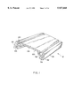
- FIG. 1 is a perspective view of a framing member forming part of the mounting apparatus of the invention
- FIG. 2 is an end view of the framing member of FIG. 1;
- FIG. 3 is a plan view of the framing member shown in FIG. 1;
- FIG. 4 is a bottom view of the framing member shown in FIG. 1;
- FIG. 5 is a side view of a connecting piece or member used to connect framing members as shown in FIG. 1;
- FIG. 6 is an end view of the connecting pieces or member shown in FIG. 5;
- FIG. 7 is a perspective inside view of a corner piece of the mounting system of the invention.
- FIG. 8 is a perspective outside view of a corner piece of the mounting system of the invention.
- FIG. 9 is a perspective view of the outer side of a corner cover of the mounting system of the invention.
- FIG. 10 is a perspective view of the inner side of a corner cover shown in FIG. 9;
- FIG. 11 is a view of a cable of the mounting system
- FIG. 12 is a plan view of a first embodiment of a cable tensioning apparatus of the mounting system of the invention.
- FIG. 13 is a second embodiment of the cable tensioning apparatus of the mounting system of the invention.
- FIG. 14 is a perspective view, partially exploded, of a mounting system of the invention.
- FIG. 15 is a detail of the corner arrangement of the mounting system shown in FIG. 14;
- FIG. 16 shows second embodiment of a framing member of the invention.
- FIGS. 17a and 17b shows the framing member of FIG. 16 in conjunction with an adapter plate for use therewith.
- the present invention relates to an apparatus for mounting objects, as well as a mounting system.
- the apparatus for mounting objects comprises a framing member 12, best illustrated in FIGS. 1 and 2 of the drawings.
- the mounting system includes a mounting frame 14, the mounting frame 14 including at least two framing members 12, joined together by a connecting pieces or member 16, best shown in FIG. 5, a cable 18, a corner piece 20, best shown in FIG. 7 and a corner cover 22, best shown in FIGS. 9 and 10.
- a framing member 12 having a body portion 24, and two depending side walls 26 and 28.
- the body portion 24 is slightly convex.
- each slot having an entry channel 34 and 36 which leads into the base slot 38 and 40.
- Each T-shaped slot 32 is therefore defined by a body portion projection 42 and 44, a slot wall 46 and 48, and a part of the side wall 26 and 28, each of the side walls having a side wall projection 50 and 52.
- the slot walls 46 and 48 recess inwardly towards the center making the T-shaped slot asymetrical, thus accomodating clearance to recess, out-of-view, cable 18.
- Each side wall 26, 28 further comprises an inwardly extending flange 54 which, with the remainder of the side wall 28 and the slot wall 48 defines a groove 56 which is continuous and runs down the entire the length of the framing member 12.
- the groove 56 has a widened end 58 at the closed end thereof.
- a plurality of framing members 12 may be connected to each other so as to define a frame which is adjustable in size, and may assume just about any shape or configuration which may be necessary depending upon the object which the mounting frame 14 is intended to support.
- Any two adjacent framing members 12 may be connected together by a connecting pieces or member 16, best shown in FIGS. 5 and 6 of the drawings.
- the connecting piece or member 16 shown in FIG. 5 has a first portion 60 and a second portion 62, the first and second portions being at substantially right angles to each other.
- the connecting pieces or member 16 may have first and second portions which are other than at right angles to each other, depending on the shape of the frame that is to be constructed.
- the connecting member 16 may simply comprise a substantially plane or straight piece; in other words, such a connecting member has the first and second portions at 180° to each other. In this latter instance, the connecting member 16 will join a pair of adjacent framing members 12 where the framing members are intended to be continuous, and not to define an angle therebetween.
- the connecting piece 16 has a defined width for a particular framing member 12, and comprises a tongue 64 at each end thereof.
- the tongue 64 at each end of the connecting member 16 is adapted to be received in the groove 56 of the framing member 12.
- the connecting piece will be sufficiently wide so that it extends at least into the grooves 56 of the framing member 12 but would not be wider than the distance between the side walls 26 and 28 of the framing member.
- the connecting member is preferably comprised of a series of corrugations 66, which impart additional strength to the connecting member, and limit the amount by which the connecting member may bend or give when under a load.
- the first portion 60 of the connecting member 16 has a first end 68, while the second portion 62 of the connecting member 16 has a second end 70.
- the first end 68 is inserted into the grooves 56 and space extending therebetween of the framing member 12. Since the grooves 56 are continuous, the first portion 60 of the connecting piece 16 slides down along the grooves 56, and is able to do so at least until the bend 72 in the connecting member 16.
- a mounting frame 14 constructed between the framing members 12 and connecting members 16 joining such framing members 12 is variable in size, and the extent to which the first and second portions 60 and 62 of the connecting members 16 extend longitudinally between the continuous grooves 56 of the framing member 12 will in large part depend upon the size of the mounting frame 14 to be constructed, which is in turn dependent on the article or object which the mounting frame 14 is intended to support.
- FIGS. 7 and 8 there is shown a cornerpiece 20 comprising a pair of flat surfaces 74 and 76 at substantially right angles to each other.
- Each flat surface 74 and 76 has an outer side 78, best shown in FIG. 7, and an inner side 80 which can be seen in FIG. 8.
- each of the flat surfaces 74 and 76 there is provided a flat hybrid synthetic/rubber or rubber-like material 82 which typically has a very high coefficient of friction.
- a suitable material is available under the trade name Santoprene (among others).
- the outer side 78 of the cornerpiece has running therealong a series of rib-like projections 84 extending from one end of the flat surface 74 to the opposite end of the flat surface 76.
- the cornerpiece 20 is intended to be located between the pair of adjacently connected framing members 12 and the object or article which is mount mounted.
- the outer side 78 is, at least along some of its surface area, applied to a pair of adjacent framing members 12, while the inner side 80, and particularly the rubber-like material 82 thereof, is in contact with the object or article to be mounted.
- the rubber-like material 82 with the high coefficient of friction, prevents slipping or sliding of the article relative to the cornerpiece 20, especially when the cornerpiece 20 is pushed against the object or article with some force.
- the rib-like projections 84 facilitate a firm connection between the cornerpiece 20 and adjacent framing members (12) to further ensure that no slipping takes place.
- a corner cover 22 which, in the fully assembled mounting frame 14, essentially has an aesthetic or design function, and covers up the joined ends of the framing member 12 and the cornerpiece 20.
- the corner cover 22 has a pair of first and second walls 86 and 88 respectively, each of the walls 86 and 88 having a depending side wall 90.
- a number of tabs 92 are provided so that the corner cover 22 can be attached in a slide-on and snap-fit fashion to the framing members 12.
- the tabs 92 are located so as to snap behind side walls 26 and 28 at tab-connecting point 94 shown, for example, in FIG. 2 of the drawings. While the tabs 92 constitute a secure fit, it is to be noted that they can also be removed since the cover corner 22 is generally comprised of a plastic material and can be sufficiently bent to remove the corner cover 22 should access or disassembly become necessary.
- the various components of the system of the present invention can be assembled to form a mounting frame 14 generally shown in FIG. 14 of the drawings.
- four framing members 12a, 12b, 12c and 12d are arranged with respect to each other so as to form a rectangle.
- the desired size of the rectangle would be used to hold a monitor for a computer or a television set.
- the various framing members 12 can be arranged to form any desired shape or configuration, including an annular shape and configuration according to the article to be mounted.
- connecting piece 16a connects at right angles to each other the framing members 12a and 12d; connecting piece 16d connects the framing members 12d and 12c together at substantially right angles to each other; connecting piece 16c connects together mounting members 12c and 12b at substantially right angles to each other; and connecting piece 16b connects together the framing members 12a and 12b at substantially right angle to each other.
- the connecting members 16a-16d are capable of sliding movement within the continuous grooves 56 of their associated forming members 12a14 12d so that, at least at this stage, there is some flexibility with respect to the size of the rectangle which the various framing members 12a-12d and connecting members 16a-16d may define. Furthermore, the extent of the flexibility can be varied according to the lengths of the first and second portions 60 and 62 of the connecting members 16. The longer the first and second portions 61 and 62 are, the more such first and second portions 60 and 62 may extend outside the track defined by the grooves 56 on the framing member 12, and the larger the rectangle defined by the various components may be. Range of movement may be defined and limited aesthetically by the length of the walls 86 and 88 of the corner cover. However the framing system would still remain functionally operative if the connecting member end became visible.
- a cable 18 extends through and/or within each of the frame members 12a-12d and connecting members 16a-16d.
- the slot base 38 and 40 of the continuous T-shaped slots 30 and 32 are adapted to receive the cable 18.
- the cable is inserted into the T-shaped slot through the entry channels 34 and 36, and thereafter moved into the inner portion of the base slots 38 and 40 respectively.
- the position of the cable 18 is shown in phantom lines in the base slots 38 and 40 of the T-shaped slots 30 and 32.
- the cable 18 extends through the base slot 38 and 40 of the T-shaped slots 30 and 32 of each of the framing members 12a-12d, and then passes over the outer side of each connecting piece 16a-16d. It is prevented from any substantial movement as it passes over each connecting piece 16a-16d by virtue of the corrugations 66.
- the corrugations 66 provide two troughs, one on each side of the connecting piece 16, and each trough is designed to receive the cable 18.
- the trough offers a path for the cable 18 which continues off from the base slots 38 and 40.
- the trough also serves to initially position, and maintain the position of, the cable 18 in the location allocated therefor.
- the cable 18 has a first end 96 and a second end 98 which joins to the first end 96 in any suitable matter.
- a description of two embodiments of the cable connection and tensioning apparatus which may be used in accordance with this invention is described (see FIGS. 12 and 13).
- a cable tensioning apparatus 100 Between the first end 96 and the second end 98 on the cable 18, there is preferably provided a cable tensioning apparatus 100.
- the use of a cable tensioning apparatus means is preferable since the cable can, over time, slip or loosen.
- the compression spring also provides additional travel, essential to facilitate adequate travel during tensioning.
- the tensioning apparatus 100 may include a ring clamp 102 near the first end 96 of the cable 18.
- a first tie 104 with a hook 106 and 108 at each end thereof is provided.
- the hook 106 engages the ring clamp 102, while the hook, 108 extends through a compression spring 110, around which it attaches.
- a second tie 112, also having a hook 114 and 116 at each end is provided.
- the hook 114 of the second tie 112 extends through and around the compression spring 110, while the hook 116 on the second tie 112 is available for connection to the second end 98 of the cable 18.
- the first and second ends 96 and 98 of the cable 18 may be attached in a fixed manner to a part of the mounting frame.
- the framing members 12a-12d and connecting piece or members 16a-16d are assembled with respect to each other as shown in FIG. 14, and two cables are threaded through the framing members 12a-12d and connecting members 16a-16d as described above.
- the cable is held loosely, so that the area defined by the mounting frame 14 is slightly larger than the object to be mounted.
- the tensioning means 100 is intended to incorporate two independently functioning cable assemblies, either one of which will support the object at the maximum rated load, should one cable assembly not operate at any time.
- a cornerpiece 20 is placed at each of the four corners of the object to be mounted.
- the rubber-like material 82 is permanently affixed to the cornerpiece 20.
- Each cornerpiece 20, mounted at a corner of the object will remain in contact therewith and is unlikely to slip because of the high coefficient of friction created by the rubber-like material 82.
- the object and mounting frame 14 With each cornerpiece in position, the object and mounting frame 14 are brought into registry with each other so that the mounting frame surrounds the object at those points where the connecting members are located. In this position, the mounting frame 14 is ready to be tightened and secured so that the object is firmly held therein.
- the cable is tightened drawing the framing members 12a-12d and connecting members 16a-16d more closely and more tightly together, and bringing compressive pressure on the object through surface contact with the rubber-like material 82 on the cornerpieces 20.
- the cornerpieces 20 and rubber-like material 82 will be firmly wedged between the object being mounted and the mounting frame 14 defined by the framing members 12a-12d and connecting members 16a-16d.
- the ends of the cable 18 are secured so that further movement of the cable is not permitted.
- the object such as a television monitor, therefore now has a mounting frame 14 securely tightened about its perimeter.
- the mounting frame when used to mount, for example, a television monitor, is intended to be positioned in line with the television monitor's center of gravity situated in almost all cases at the very front of the television monitor enclosure.
- a corner cover 22 may be placed on and snapped into position at each corner so as to cover the join between the adjacent framing members 12 and to cover the particular connecting piece 16.
- the corner cover 22 thus provides an appealing appearance and finishes off, from an aesthetic point of view, the mounting frame 14.
- the corner covers 22 have a snap-fit connection to the frame member 12, with the tabs 92 of the corner cover 22 fitting around the tab connecting point 94 of the framing member 12.
- the corner cover 22 can be easily removed, being made of plastic material, for appropriate adjustment or disassembly of the mounting frame 14 as necessary.
- the entire mounting frame is intended to present a low, unobtrusive profile in relation to the object or device to be mounted.
- the framing members 12 and connecting members 16 are generally comprised of aluminum or steel, particularly where the object to be mounted is heavy. For smaller, lightweight objects, these components may be comprised of strong plastic such as polyurethane and/or polycarbonates.
- FIG. 12 shows another embodiment of a cable tensioning apparatus for use in the present invention.
- a base plate 118 is provided which is adapted to lie below the body portion 24 of the framing member 12. Thus, the base plate 118 will typically abut or be adjacent to the inner surface 120 of the body portion 24.
- Each cable wheel 122 and 124 incorporates a ratchet gear wheel 126 and 128 and a corresponding pawl 130 and 132.
- a pawl spring 134 Associated with each pawl 130 and 132 is a pawl spring 134.
- the body portion 24 of the framing member 12 will have holes therein corresponding to the position of the hub 136 of each wheel 122 and 124, and with the use of appropriate tools, extending through the hole, the cable wheels 122 and 124 can be turned to effect the necessary tightening and tensioning of the cable to securely hold the mounting frame 14 in the desired position.
- FIG. 13 shows yet another embodiment of a cable tensioning apparatus with conventional cable wheels which can be tightened to effect the necessary tension in the cable, and the wheels thereafter bolted securely to the base plate 118.
- FIG. 16 there is shown a second embodiment of a framing member 212, which is in all material aspects identical to the framing member 12 shown in FIGS. 1-3, except that the side walls 26 and 28 are shorter, and no flange 54 is provided. There will, of course, be no groove 56.
- a mounting member of the type shown in FIG. 16 may be used for a different mounting purpose.
- an extended extrusion of the framing member 212 may be bolted to a wall, and an adapter plate 214 is structured so as to be received and slide within the T-shaped slots 30 and 32.
- Each adapter plate 214 an example of which is shown in FIGS.
- Each adapter plate 214 includes a fixing means which may comprise a bolt in a threaded hole. As the bolt is tightened, it will apply pressure to the body portion, thus fixing the adapter plate with respect to the body portion. The adapter plate is then available for use, and, depending on its shape and configuration, will either support or permit to be mounted desired objects.
- the framing member 12 shown in FIGS. 1-3 is also capable of mounting on a wall so that an adapter plate 214 may slide within the T-shaped slots 230 and 232.
- an advantage of mounting a framing member 12 of the type shown in FIGS. 1-3 against a wall is that the mounting pieces may be located behind the body portion, namely, between the body portion and the wall, and therefore not be visible when mounted.
- An adapter may therefore comprise a plate which slides in and is received in the continuous grooves 56, the plate being mounted to the wall. Once the plate is mounted to the wall, the framing member 12 is located over the plate, and one or more such plates may hold the framing member 12 in position.
- the plate may be integrated as part of a die-cast and cap fitting that both dresses-down the end of framing member 12 and slides into the continuous grooves 56 of the framing member 12.
- the framing member 12 in conjunction with connecting members 16 of different angle, can be used to create a frame of just about any size and shape, and therefore be easily adapted to mounting the object desired.
- the articles or objects which may be mounted by a system described in the present invention include computer monitors, television sets, cameras, VCRs, speakers, computers, printers, microwave ovens and a host of other electronic equipment.
- the components of the present invention additionally provide an aesthetically pleasing, low-profile frame which would, from a design point of view, enhance the appearance of a residential media center, home theaters or any other environment in which it is located.
- the invention has applications not only in residential media centers, home theaters but also with respect to commercial displays in retail outlets, positioning of electronic equipment in theaters, cinemas, broadcast and production facilities and corporate boardrooms and the like.
- the mounting frame 14 is attached to any suitable and/or conventional mounting system 138, as shown in FIG. 14 of the drawings.
- desired mounting systems which may comprise ball and socket connections or elbow joints, the frame, together with the object therein, can be attached to a wall, ceiling or floor so that its position is exactly as desired.
- the system also has certain advantages particularly with respect to television sets and computer monitors.
- the mounting frame 14 can be located about that portion of the object through which the center of gravity passes. When mounted in this way, the object will be relatively well “balanced” within the mounting frame, and therefore unnecessary load due to overbalancing or uncentered mounting can be avoided.
- This system also provides a particularly secure connection with the object.
- the object mounted will not easily be displaced from the mounting frame by any unintentional knock or shaking, or any violent motion produced by an earthquake.
- the use of two fully independent cable systems in the mounting frame is an added safety feature since, if one cable were to become loose or otherwise fail in its ability to keep the mounting frame together, the other cable would still continue to function and essentially hold the mounting frame together.
- the system is also exceptionally flexible in that objects mounted can be moved, for example, from one residence to another, without actually dismantling the mounting frame 14 from the object mounted. Rather, the object will remain in the frame, and the entire structure disengaged from the floor, wall or ceiling, so that when moving the system a minimal amount of deconstruction and reassembling is necessary.
- the framing member 12 may have a configuration or shape other than that described.
- the body portion need not be arcuate, the continuous T-shaped slots may be of slightly different shape, with other small constructional changes.
- any suitable means for fastening and/or tensioning the cable may be provided.
- the cornerpiece 20 may be omitted, or be incorporated into the framing member 12 and/or connecting piece 16 which may have extensions or projections for the purpose of frictionally engaging the object to be mounted.
Abstract
Description
Claims (14)
Priority Applications (3)
| Application Number | Priority Date | Filing Date | Title |
|---|---|---|---|
| US08/579,868 US5927668A (en) | 1995-12-28 | 1995-12-28 | Adjustable framing support system |
| US09/055,600 US6102350A (en) | 1995-12-28 | 1998-04-06 | Apparatus for mounting objects, including tension member |
| US09/332,957 US6318692B1 (en) | 1995-12-28 | 1999-06-14 | Adjustable framing support system |
Applications Claiming Priority (1)
| Application Number | Priority Date | Filing Date | Title |
|---|---|---|---|
| US08/579,868 US5927668A (en) | 1995-12-28 | 1995-12-28 | Adjustable framing support system |
Related Parent Applications (1)
| Application Number | Title | Priority Date | Filing Date |
|---|---|---|---|
| US09/055,600 Continuation US6102350A (en) | 1995-12-28 | 1998-04-06 | Apparatus for mounting objects, including tension member |
Related Child Applications (3)
| Application Number | Title | Priority Date | Filing Date |
|---|---|---|---|
| US09/055,600 Continuation-In-Part US6102350A (en) | 1995-12-28 | 1998-04-06 | Apparatus for mounting objects, including tension member |
| US29/103,594 Division USD423910S (en) | 1999-04-16 | 1999-04-16 | Equipment mount |
| US09/332,957 Continuation US6318692B1 (en) | 1995-12-28 | 1999-06-14 | Adjustable framing support system |
Publications (1)
| Publication Number | Publication Date |
|---|---|
| US5927668A true US5927668A (en) | 1999-07-27 |
Family
ID=24318683
Family Applications (2)
| Application Number | Title | Priority Date | Filing Date |
|---|---|---|---|
| US08/579,868 Expired - Fee Related US5927668A (en) | 1995-12-28 | 1995-12-28 | Adjustable framing support system |
| US09/332,957 Expired - Fee Related US6318692B1 (en) | 1995-12-28 | 1999-06-14 | Adjustable framing support system |
Family Applications After (1)
| Application Number | Title | Priority Date | Filing Date |
|---|---|---|---|
| US09/332,957 Expired - Fee Related US6318692B1 (en) | 1995-12-28 | 1999-06-14 | Adjustable framing support system |
Country Status (1)
| Country | Link |
|---|---|
| US (2) | US5927668A (en) |
Cited By (28)
| Publication number | Priority date | Publication date | Assignee | Title |
|---|---|---|---|---|
| US6098944A (en) * | 1999-05-05 | 2000-08-08 | Weber Knapp Company | Holder for supporting a component below a support |
| US6102350A (en) * | 1995-12-28 | 2000-08-15 | Omnimount Systems, Inc. | Apparatus for mounting objects, including tension member |
| US6318692B1 (en) * | 1995-12-28 | 2001-11-20 | Alexander Cyrell | Adjustable framing support system |
| US6402111B1 (en) * | 1999-06-07 | 2002-06-11 | Accuride International, Inc. | CPU mounting unit |
| US6460817B1 (en) * | 2000-04-03 | 2002-10-08 | Peter Thomas Bosson | CPU holder |
| US20020186859A1 (en) * | 2001-06-12 | 2002-12-12 | Atia Gerardo W. | Framework for home theater systems |
| US20040113895A1 (en) * | 2002-08-23 | 2004-06-17 | Ceronix, Inc. | Method and apparatus of position location |
| US6986491B2 (en) | 2002-11-12 | 2006-01-17 | Knape & Vogt Manufacturing Co. | CPU holder |
| US7077373B1 (en) * | 2000-01-05 | 2006-07-18 | Da-Lite Screen Co., Inc. | Mount for TV monitor |
| US20070211037A1 (en) * | 2006-03-09 | 2007-09-13 | Sun Brian Y | Photoelectric sensing array apparatus |
| US7377475B1 (en) * | 2005-07-22 | 2008-05-27 | Rodovaldo Lopez | Television mount assembly |
| US20080234856A1 (en) * | 2007-03-23 | 2008-09-25 | Manuel Saez | Adjustable Computer Component Mounting System |
| WO2008118169A1 (en) * | 2007-03-23 | 2008-10-02 | Humanscale Corporation | Adjustable computer component mounting system |
| US7469485B1 (en) | 2007-05-10 | 2008-12-30 | Joab Jay Perdue | Apparatus for replicating quadrilateral shapes |
| US20090013624A1 (en) * | 2007-02-05 | 2009-01-15 | Peter Sibbett | Window frame |
| US20100012801A1 (en) * | 2008-07-18 | 2010-01-21 | Peerless Industries, Inc. | Surface Mounting System |
| US20100045943A1 (en) * | 2008-08-25 | 2010-02-25 | Peerless Industries, Inc. | Projector Mount |
| US20100142128A1 (en) * | 2007-03-30 | 2010-06-10 | Yoshihiro Takechi | Frame casing and display device |
| FR2954246A1 (en) * | 2009-12-23 | 2011-06-24 | Faurecia Interieur Ind | Device for maintaining e.g. personal digital assistant in fascia of motor vehicle, has retaining elements displaced towards center of rectangular support surface between opening position and maintaining position |
| US20110224003A1 (en) * | 2010-03-10 | 2011-09-15 | Ksm Inc. | Permanently Adaptable Gaming Mount |
| US20120170278A1 (en) * | 2009-08-19 | 2012-07-05 | Wolfgang-Peter Geller | Portable light manipulator |
| CN102588899A (en) * | 2012-03-19 | 2012-07-18 | 深圳市华星光电技术有限公司 | Spliced rubber frame and backlight module with same |
| US9403623B2 (en) | 2013-07-05 | 2016-08-02 | Craig L. Aaland | Adjustable, reusable packing crate |
| US20170145677A1 (en) * | 2015-11-25 | 2017-05-25 | Flo-Water, Llc | Water inlet protection system |
| GR1009076B (en) * | 2016-06-07 | 2017-07-07 | Κωνσταντινος Νικολαου Γεωργιαδης | Aluminium profile for curtain's front part |
| US10392815B1 (en) * | 2017-11-08 | 2019-08-27 | Litania Sports Group, Inc. | Wall pad sleeve |
| US10429884B1 (en) * | 2017-12-14 | 2019-10-01 | David W. Brittingham | Adjustable monitor frame for retaining and displaying a book and thin planar objects |
| US10822827B1 (en) * | 2019-09-09 | 2020-11-03 | Ray Yan | Multifunctional racks, sunshades and tents on floating devices |
Families Citing this family (14)
| Publication number | Priority date | Publication date | Assignee | Title |
|---|---|---|---|---|
| US6581954B2 (en) * | 2000-06-26 | 2003-06-24 | Michael Chadwick | Multi-use motorcycle apparatus and method therefor |
| US6926258B1 (en) * | 2004-09-09 | 2005-08-09 | Illinois Tool Works, Inc. | Biased strap tension retaining device |
| US20060196094A1 (en) * | 2005-02-01 | 2006-09-07 | Robin Sturmthal | Decorative computer monitor frame |
| US20070018062A1 (en) * | 2005-07-20 | 2007-01-25 | Theodor Calinescu | Universal wall mount bracket for displays |
| US7793907B2 (en) * | 2007-04-20 | 2010-09-14 | Robert Woodward | Monitor suspension device and method of use |
| US7988114B2 (en) * | 2009-06-13 | 2011-08-02 | Coleman Joseph C | Adjustable electronic device holder |
| US8550574B2 (en) | 2009-07-08 | 2013-10-08 | Logic Exhibit System Ltd. | Modular exhibit structure |
| US8668123B2 (en) * | 2010-03-10 | 2014-03-11 | Julian Richmond | Holding apparatus for a portable electronic device |
| US8561801B2 (en) | 2011-08-01 | 2013-10-22 | International Business Machines Corporation | Machinery packaging system |
| US9146001B2 (en) * | 2012-02-01 | 2015-09-29 | Peerless Industries, Inc. | Endcap mounting system for mounting audio/visual devices or the like |
| US10292282B1 (en) * | 2013-10-14 | 2019-05-14 | Mark PLATT | Adjustable holder for an electronic device |
| DE102013021770A1 (en) * | 2013-12-20 | 2015-06-25 | Haseke Gmbh & Co. Kg | Housing for the installation of screens and / or control panels |
| AU2019202011B1 (en) * | 2019-03-13 | 2019-08-01 | Zibo Junkang Stationery Co., Ltd. | A Sound Stand |
| US11719269B2 (en) * | 2021-07-12 | 2023-08-08 | Chiao-Yin CHANG | Corner bracket with reinforcing ribs |
Citations (25)
| Publication number | Priority date | Publication date | Assignee | Title |
|---|---|---|---|---|
| DE181133C (en) * | 1900-01-01 | |||
| DE457013C (en) * | 1928-03-07 | Julius Klement | Frame tensioning device | |
| US2204493A (en) * | 1938-02-09 | 1940-06-11 | James N Henry | Curtain rod |
| US2611949A (en) * | 1949-10-08 | 1952-09-30 | Wanamaker Seth | Toilet tank fitting holding tool |
| US2831808A (en) * | 1955-10-14 | 1958-04-22 | George J Esseff | Article supporting rack |
| US3429602A (en) * | 1967-04-26 | 1969-02-25 | Alusuisse | Welded light-metal corner construction |
| US3451153A (en) * | 1967-05-08 | 1969-06-24 | John A Dohanyos | Adjustable framing device |
| US3784043A (en) * | 1968-11-29 | 1974-01-08 | M Presnick | Lightweight collapsible structures |
| US4027866A (en) * | 1975-12-29 | 1977-06-07 | Arthur Ruggiero | Multi-face clamp for manufacturing or regluing of drawers, chairs or the like |
| US4031796A (en) * | 1976-04-28 | 1977-06-28 | Teledyne, Inc. | Solenoid mounting assembly for musical keyboard |
| US4074811A (en) * | 1975-10-15 | 1978-02-21 | Filak Andrew M | Multi-level knock-down framework structure for supporting a plurality of objects |
| US4356648A (en) * | 1981-05-08 | 1982-11-02 | Rupp Industries, Inc. | Framing system for display panels |
| US4450655A (en) * | 1982-08-25 | 1984-05-29 | Rosenthal Michael R | Vertically slotted panel |
| US4831804A (en) * | 1987-09-17 | 1989-05-23 | Thermal Profiles, Inc. | Window frame apparatus |
| US4924649A (en) * | 1989-07-13 | 1990-05-15 | Innovative Building Products, Inc. | Corner assembly for a skylight frame |
| GB2231995A (en) * | 1989-05-20 | 1990-11-28 | Signco Ltd | Framing |
| US4997155A (en) * | 1988-02-22 | 1991-03-05 | Rittal-Werk Rudolf Loh Gmbh & Co. Kg | Suspension apparatus for control devices |
| US5064161A (en) * | 1991-01-10 | 1991-11-12 | Anderson Timothy W | Universal ceiling mount assembly for television monitor |
| US5161789A (en) * | 1991-08-27 | 1992-11-10 | Rogers Winston L | Universal clamping device |
| US5165644A (en) * | 1991-07-25 | 1992-11-24 | Thomas Allen | Mounting apparatus for a video display |
| US5310152A (en) * | 1992-01-08 | 1994-05-10 | Lucasey Manufacturing Company | Television mounting support with removable lifting assembly |
| US5393025A (en) * | 1993-10-21 | 1995-02-28 | Franklin; Harry C. | Cabinet mounting harness |
| US5400993A (en) * | 1993-08-17 | 1995-03-28 | Hamilton; Clifton | Adjustable overhead suspension apparatus for TV and VCR |
| US5411244A (en) * | 1994-03-04 | 1995-05-02 | Turner; Tommy P. | Clamp using elastic tension member |
| US5538214A (en) * | 1994-07-27 | 1996-07-23 | Sinila; Alexander | Locking accessory support apparatus |
Family Cites Families (5)
| Publication number | Priority date | Publication date | Assignee | Title |
|---|---|---|---|---|
| US542966A (en) * | 1895-07-16 | Wire fence | ||
| US565916A (en) * | 1896-08-18 | Wire fence | ||
| US2539997A (en) * | 1949-09-06 | 1951-01-30 | Lester R Graves | Car top fastener for boats and other articles |
| US5402557A (en) * | 1993-05-03 | 1995-04-04 | Dalen; Thomas M. | Dynamic self-adjusting tie-down device for transportable items |
| US5927668A (en) * | 1995-12-28 | 1999-07-27 | Omni Mount Systems, Inc. | Adjustable framing support system |
-
1995
- 1995-12-28 US US08/579,868 patent/US5927668A/en not_active Expired - Fee Related
-
1999
- 1999-06-14 US US09/332,957 patent/US6318692B1/en not_active Expired - Fee Related
Patent Citations (25)
| Publication number | Priority date | Publication date | Assignee | Title |
|---|---|---|---|---|
| DE181133C (en) * | 1900-01-01 | |||
| DE457013C (en) * | 1928-03-07 | Julius Klement | Frame tensioning device | |
| US2204493A (en) * | 1938-02-09 | 1940-06-11 | James N Henry | Curtain rod |
| US2611949A (en) * | 1949-10-08 | 1952-09-30 | Wanamaker Seth | Toilet tank fitting holding tool |
| US2831808A (en) * | 1955-10-14 | 1958-04-22 | George J Esseff | Article supporting rack |
| US3429602A (en) * | 1967-04-26 | 1969-02-25 | Alusuisse | Welded light-metal corner construction |
| US3451153A (en) * | 1967-05-08 | 1969-06-24 | John A Dohanyos | Adjustable framing device |
| US3784043A (en) * | 1968-11-29 | 1974-01-08 | M Presnick | Lightweight collapsible structures |
| US4074811A (en) * | 1975-10-15 | 1978-02-21 | Filak Andrew M | Multi-level knock-down framework structure for supporting a plurality of objects |
| US4027866A (en) * | 1975-12-29 | 1977-06-07 | Arthur Ruggiero | Multi-face clamp for manufacturing or regluing of drawers, chairs or the like |
| US4031796A (en) * | 1976-04-28 | 1977-06-28 | Teledyne, Inc. | Solenoid mounting assembly for musical keyboard |
| US4356648A (en) * | 1981-05-08 | 1982-11-02 | Rupp Industries, Inc. | Framing system for display panels |
| US4450655A (en) * | 1982-08-25 | 1984-05-29 | Rosenthal Michael R | Vertically slotted panel |
| US4831804A (en) * | 1987-09-17 | 1989-05-23 | Thermal Profiles, Inc. | Window frame apparatus |
| US4997155A (en) * | 1988-02-22 | 1991-03-05 | Rittal-Werk Rudolf Loh Gmbh & Co. Kg | Suspension apparatus for control devices |
| GB2231995A (en) * | 1989-05-20 | 1990-11-28 | Signco Ltd | Framing |
| US4924649A (en) * | 1989-07-13 | 1990-05-15 | Innovative Building Products, Inc. | Corner assembly for a skylight frame |
| US5064161A (en) * | 1991-01-10 | 1991-11-12 | Anderson Timothy W | Universal ceiling mount assembly for television monitor |
| US5165644A (en) * | 1991-07-25 | 1992-11-24 | Thomas Allen | Mounting apparatus for a video display |
| US5161789A (en) * | 1991-08-27 | 1992-11-10 | Rogers Winston L | Universal clamping device |
| US5310152A (en) * | 1992-01-08 | 1994-05-10 | Lucasey Manufacturing Company | Television mounting support with removable lifting assembly |
| US5400993A (en) * | 1993-08-17 | 1995-03-28 | Hamilton; Clifton | Adjustable overhead suspension apparatus for TV and VCR |
| US5393025A (en) * | 1993-10-21 | 1995-02-28 | Franklin; Harry C. | Cabinet mounting harness |
| US5411244A (en) * | 1994-03-04 | 1995-05-02 | Turner; Tommy P. | Clamp using elastic tension member |
| US5538214A (en) * | 1994-07-27 | 1996-07-23 | Sinila; Alexander | Locking accessory support apparatus |
Cited By (38)
| Publication number | Priority date | Publication date | Assignee | Title |
|---|---|---|---|---|
| US6102350A (en) * | 1995-12-28 | 2000-08-15 | Omnimount Systems, Inc. | Apparatus for mounting objects, including tension member |
| US6318692B1 (en) * | 1995-12-28 | 2001-11-20 | Alexander Cyrell | Adjustable framing support system |
| EP0949445A3 (en) * | 1998-04-06 | 2002-01-16 | OmniMount Systems, Inc. | Apparatus for mounting objects |
| US6098944A (en) * | 1999-05-05 | 2000-08-08 | Weber Knapp Company | Holder for supporting a component below a support |
| US6402111B1 (en) * | 1999-06-07 | 2002-06-11 | Accuride International, Inc. | CPU mounting unit |
| US7077373B1 (en) * | 2000-01-05 | 2006-07-18 | Da-Lite Screen Co., Inc. | Mount for TV monitor |
| US6460817B1 (en) * | 2000-04-03 | 2002-10-08 | Peter Thomas Bosson | CPU holder |
| US20020186859A1 (en) * | 2001-06-12 | 2002-12-12 | Atia Gerardo W. | Framework for home theater systems |
| US6933931B2 (en) | 2002-08-23 | 2005-08-23 | Ceronix, Inc. | Method and apparatus of position location |
| US20040113895A1 (en) * | 2002-08-23 | 2004-06-17 | Ceronix, Inc. | Method and apparatus of position location |
| US6986491B2 (en) | 2002-11-12 | 2006-01-17 | Knape & Vogt Manufacturing Co. | CPU holder |
| US7377475B1 (en) * | 2005-07-22 | 2008-05-27 | Rodovaldo Lopez | Television mount assembly |
| US20070211037A1 (en) * | 2006-03-09 | 2007-09-13 | Sun Brian Y | Photoelectric sensing array apparatus |
| US20090013624A1 (en) * | 2007-02-05 | 2009-01-15 | Peter Sibbett | Window frame |
| US7845135B2 (en) * | 2007-02-05 | 2010-12-07 | Peter Sibbett | Window frame |
| CN101641038B (en) * | 2007-03-23 | 2012-10-03 | 休思乐公司 | Adjustable computer component mounting system |
| WO2008118169A1 (en) * | 2007-03-23 | 2008-10-02 | Humanscale Corporation | Adjustable computer component mounting system |
| US8141836B2 (en) | 2007-03-23 | 2012-03-27 | Humanscale Corporation | Adjustable computer component mounting system |
| US20080234856A1 (en) * | 2007-03-23 | 2008-09-25 | Manuel Saez | Adjustable Computer Component Mounting System |
| US20100142128A1 (en) * | 2007-03-30 | 2010-06-10 | Yoshihiro Takechi | Frame casing and display device |
| US8559169B2 (en) | 2007-03-30 | 2013-10-15 | Nec Display Solutions, Ltd. | Frame casing and display device |
| US8284548B2 (en) * | 2007-03-30 | 2012-10-09 | Nec Display Solutions, Ltd. | Frame casing and display device |
| US7469485B1 (en) | 2007-05-10 | 2008-12-30 | Joab Jay Perdue | Apparatus for replicating quadrilateral shapes |
| US20100012801A1 (en) * | 2008-07-18 | 2010-01-21 | Peerless Industries, Inc. | Surface Mounting System |
| US7887015B2 (en) | 2008-07-18 | 2011-02-15 | Peerless Industries, Inc. | Surface mounting system |
| US20100045943A1 (en) * | 2008-08-25 | 2010-02-25 | Peerless Industries, Inc. | Projector Mount |
| US20120170278A1 (en) * | 2009-08-19 | 2012-07-05 | Wolfgang-Peter Geller | Portable light manipulator |
| US8875457B2 (en) * | 2009-08-19 | 2014-11-04 | Wolfgang-Peter Geller | Portable light manipulator |
| FR2954246A1 (en) * | 2009-12-23 | 2011-06-24 | Faurecia Interieur Ind | Device for maintaining e.g. personal digital assistant in fascia of motor vehicle, has retaining elements displaced towards center of rectangular support surface between opening position and maintaining position |
| US20110224003A1 (en) * | 2010-03-10 | 2011-09-15 | Ksm Inc. | Permanently Adaptable Gaming Mount |
| CN102588899A (en) * | 2012-03-19 | 2012-07-18 | 深圳市华星光电技术有限公司 | Spliced rubber frame and backlight module with same |
| CN102588899B (en) * | 2012-03-19 | 2016-08-10 | 深圳市华星光电技术有限公司 | Spliced glue frame and there is the backlight module of this spliced glue frame |
| US9403623B2 (en) | 2013-07-05 | 2016-08-02 | Craig L. Aaland | Adjustable, reusable packing crate |
| US20170145677A1 (en) * | 2015-11-25 | 2017-05-25 | Flo-Water, Llc | Water inlet protection system |
| GR1009076B (en) * | 2016-06-07 | 2017-07-07 | Κωνσταντινος Νικολαου Γεωργιαδης | Aluminium profile for curtain's front part |
| US10392815B1 (en) * | 2017-11-08 | 2019-08-27 | Litania Sports Group, Inc. | Wall pad sleeve |
| US10429884B1 (en) * | 2017-12-14 | 2019-10-01 | David W. Brittingham | Adjustable monitor frame for retaining and displaying a book and thin planar objects |
| US10822827B1 (en) * | 2019-09-09 | 2020-11-03 | Ray Yan | Multifunctional racks, sunshades and tents on floating devices |
Also Published As
| Publication number | Publication date |
|---|---|
| US6318692B1 (en) | 2001-11-20 |
Similar Documents
| Publication | Publication Date | Title |
|---|---|---|
| US5927668A (en) | Adjustable framing support system | |
| US6102350A (en) | Apparatus for mounting objects, including tension member | |
| US11231154B2 (en) | Bar hanger assembly with mating telescoping bars | |
| KR100766814B1 (en) | Cleanroom wall system | |
| CA2470525C (en) | Universal wall mounting bracket | |
| EP0527658B1 (en) | Shelving | |
| US5201896A (en) | Universal audio speaker mounting bracket | |
| US20180347749A1 (en) | Mounting track for retaining a mount assembly | |
| US8542499B2 (en) | Multi-position mount for electronic display | |
| US10066783B2 (en) | Support assembly for vertically disposed objects, such as televisions and video monitors | |
| US20140064547A1 (en) | Articulating Microphone Mount | |
| US5736673A (en) | Cable and mounting bracket assembly and method | |
| US11085579B2 (en) | Mounting track for retaining a mount assembly | |
| USD374737S (en) | Lamp | |
| US5544865A (en) | Rail support bracket | |
| CA2054468A1 (en) | Spatial fastening device | |
| US20220015540A1 (en) | Modular support assembly for vertically disposed objects including televisions and video monitors | |
| US5584156A (en) | Modular structural framing system | |
| US6751913B2 (en) | Vertical wall structure with electrical service | |
| CN215647688U (en) | Telecommunication cabinet with hidden anti-theft heat dissipation module | |
| KR100528583B1 (en) | Apparatus for mounting display set | |
| EP3586676B1 (en) | A fastening mechanism and a furniture assembly | |
| JPH0974625A (en) | Box mounting device | |
| US20240011624A1 (en) | Toolless snap-fit adaptor module for integrating spot head luminaires | |
| US7384174B2 (en) | Articulating lighting system and lamp frame |
Legal Events
| Date | Code | Title | Description |
|---|---|---|---|
| FPAY | Fee payment |
Year of fee payment: 4 |
|
| AS | Assignment |
Owner name: UBS AG, STAMFORD BRANCH, AS U.S. ADMINISTRATIVE AG Free format text: SECURITY INTEREST;ASSIGNORS:BROAN-NUTONE LLC;ELAN HOME SYSTEMS, L.L.C.;JENSEN INDUSTRIES, INC.;AND OTHERS;REEL/FRAME:015918/0359 Effective date: 20040827 |
|
| REMI | Maintenance fee reminder mailed | ||
| LAPS | Lapse for failure to pay maintenance fees | ||
| STCH | Information on status: patent discontinuation |
Free format text: PATENT EXPIRED DUE TO NONPAYMENT OF MAINTENANCE FEES UNDER 37 CFR 1.362 |
|
| FP | Lapsed due to failure to pay maintenance fee |
Effective date: 20070727 |
|
| AS | Assignment |
Owner name: NORTEK, INC., RHODE ISLAND Free format text: RELEASE OF SECURITY INTEREST IN INTELLECTUAL PROPERTY;ASSIGNOR:UBS AG, STAMFORD BRANCH, AS U.S. ADMINISTRATIVE AGENT;REEL/FRAME:021118/0548 Effective date: 20080520 Owner name: NORTEK HOLDINGS, INC., RHODE ISLAND Free format text: RELEASE OF SECURITY INTEREST IN INTELLECTUAL PROPERTY;ASSIGNOR:UBS AG, STAMFORD BRANCH, AS U.S. ADMINISTRATIVE AGENT;REEL/FRAME:021118/0548 Effective date: 20080520 Owner name: MAMMOTH CHINA LTD., MINNESOTA Free format text: RELEASE OF SECURITY INTEREST IN INTELLECTUAL PROPERTY;ASSIGNOR:UBS AG, STAMFORD BRANCH, AS U.S. ADMINISTRATIVE AGENT;REEL/FRAME:021118/0548 Effective date: 20080520 Owner name: WDS LLC, RHODE ISLAND Free format text: RELEASE OF SECURITY INTEREST IN INTELLECTUAL PROPERTY;ASSIGNOR:UBS AG, STAMFORD BRANCH, AS U.S. ADMINISTRATIVE AGENT;REEL/FRAME:021118/0548 Effective date: 20080520 Owner name: CES GROUP, INC., MINNESOTA Free format text: RELEASE OF SECURITY INTEREST IN INTELLECTUAL PROPERTY;ASSIGNOR:UBS AG, STAMFORD BRANCH, AS U.S. ADMINISTRATIVE AGENT;REEL/FRAME:021118/0548 Effective date: 20080520 Owner name: JENSEN INDUSTRIES, INC., TEXAS Free format text: RELEASE OF SECURITY INTEREST IN INTELLECTUAL PROPERTY;ASSIGNOR:UBS AG, STAMFORD BRANCH, AS U.S. ADMINISTRATIVE AGENT;REEL/FRAME:021118/0548 Effective date: 20080520 Owner name: LINEAR LLC, CALIFORNIA Free format text: RELEASE OF SECURITY INTEREST IN INTELLECTUAL PROPERTY;ASSIGNOR:UBS AG, STAMFORD BRANCH, AS U.S. ADMINISTRATIVE AGENT;REEL/FRAME:021118/0548 Effective date: 20080520 Owner name: XANTECH CORPORATION, CALIFORNIA Free format text: RELEASE OF SECURITY INTEREST IN INTELLECTUAL PROPERTY;ASSIGNOR:UBS AG, STAMFORD BRANCH, AS U.S. ADMINISTRATIVE AGENT;REEL/FRAME:021118/0548 Effective date: 20080520 Owner name: MAMMOTH, INC., MINNESOTA Free format text: RELEASE OF SECURITY INTEREST IN INTELLECTUAL PROPERTY;ASSIGNOR:UBS AG, STAMFORD BRANCH, AS U.S. ADMINISTRATIVE AGENT;REEL/FRAME:021118/0548 Effective date: 20080520 Owner name: OMNIMOUNT SYSTEMS, INC., ARIZONA Free format text: RELEASE OF SECURITY INTEREST IN INTELLECTUAL PROPERTY;ASSIGNOR:UBS AG, STAMFORD BRANCH, AS U.S. ADMINISTRATIVE AGENT;REEL/FRAME:021118/0548 Effective date: 20080520 Owner name: SPEAKERCRAFT, INC., CALIFORNIA Free format text: RELEASE OF SECURITY INTEREST IN INTELLECTUAL PROPERTY;ASSIGNOR:UBS AG, STAMFORD BRANCH, AS U.S. ADMINISTRATIVE AGENT;REEL/FRAME:021118/0548 Effective date: 20080520 Owner name: BROAN-NUTONE LLC, WISCONSIN Free format text: RELEASE OF SECURITY INTEREST IN INTELLECTUAL PROPERTY;ASSIGNOR:UBS AG, STAMFORD BRANCH, AS U.S. ADMINISTRATIVE AGENT;REEL/FRAME:021118/0548 Effective date: 20080520 Owner name: MULTIPLEX TECHNOLOGY, INC. (NOW LINEAR LLC), CALIF Free format text: RELEASE OF SECURITY INTEREST IN INTELLECTUAL PROPERTY;ASSIGNOR:UBS AG, STAMFORD BRANCH, AS U.S. ADMINISTRATIVE AGENT;REEL/FRAME:021118/0548 Effective date: 20080520 Owner name: NORDYNE INC., MISSOURI Free format text: RELEASE OF SECURITY INTEREST IN INTELLECTUAL PROPERTY;ASSIGNOR:UBS AG, STAMFORD BRANCH, AS U.S. ADMINISTRATIVE AGENT;REEL/FRAME:021118/0548 Effective date: 20080520 Owner name: NUTONE INC., WISCONSIN Free format text: RELEASE OF SECURITY INTEREST IN INTELLECTUAL PROPERTY;ASSIGNOR:UBS AG, STAMFORD BRANCH, AS U.S. ADMINISTRATIVE AGENT;REEL/FRAME:021118/0548 Effective date: 20080520 Owner name: GOVERNAIR CORPORATION, OKLAHOMA Free format text: RELEASE OF SECURITY INTEREST IN INTELLECTUAL PROPERTY;ASSIGNOR:UBS AG, STAMFORD BRANCH, AS U.S. ADMINISTRATIVE AGENT;REEL/FRAME:021118/0548 Effective date: 20080520 Owner name: LINEAR H.K. LLC, CALIFORNIA Free format text: RELEASE OF SECURITY INTEREST IN INTELLECTUAL PROPERTY;ASSIGNOR:UBS AG, STAMFORD BRANCH, AS U.S. ADMINISTRATIVE AGENT;REEL/FRAME:021118/0548 Effective date: 20080520 Owner name: ELAN HOME SYSTEMS, L.L.C., KENTUCKY Free format text: RELEASE OF SECURITY INTEREST IN INTELLECTUAL PROPERTY;ASSIGNOR:UBS AG, STAMFORD BRANCH, AS U.S. ADMINISTRATIVE AGENT;REEL/FRAME:021118/0548 Effective date: 20080520 |
|
| AS | Assignment |
Owner name: BANK OF AMERICA, N.A., NEW YORK Free format text: SECURITY AGREEMENT;ASSIGNORS:NORTEK, INC.;ADVANCED BRIDGING TECHNOLOGIES, INC.;AIGIS MECHTRONICS, INC.;AND OTHERS;REEL/FRAME:021301/0927 Effective date: 20080520 Owner name: BANK OF AMERICA, N.A.,NEW YORK Free format text: SECURITY AGREEMENT;ASSIGNORS:NORTEK, INC.;ADVANCED BRIDGING TECHNOLOGIES, INC.;AIGIS MECHTRONICS, INC.;AND OTHERS;REEL/FRAME:021301/0927 Effective date: 20080520 |
|
| AS | Assignment |
Owner name: U.S. BANK NATIONAL ASSOCIATION, MASSACHUSETTS Free format text: SECURITY AGREEMENT;ASSIGNORS:NORTEK, INC.;ADVANCED BRIDGING TECHNOLOGIES, INC.;AIGIS MECHTRONICS, INC.;AND OTHERS;REEL/FRAME:021316/0764 Effective date: 20080520 Owner name: U.S. BANK NATIONAL ASSOCIATION,MASSACHUSETTS Free format text: SECURITY AGREEMENT;ASSIGNORS:NORTEK, INC.;ADVANCED BRIDGING TECHNOLOGIES, INC.;AIGIS MECHTRONICS, INC.;AND OTHERS;REEL/FRAME:021316/0764 Effective date: 20080520 |
|
| AS | Assignment |
Owner name: BANK OF AMERICA, N.A., NEW YORK Free format text: SECURITY AGREEMENT;ASSIGNORS:NORTEK, INC.;AIGIS MECHTRONICS, INC.;BROAN-MEXICO HOLDINGS, INC.;AND OTHERS;REEL/FRAME:023750/0040 Effective date: 20091217 Owner name: BANK OF AMERICA, N.A.,NEW YORK Free format text: SECURITY AGREEMENT;ASSIGNORS:NORTEK, INC.;AIGIS MECHTRONICS, INC.;BROAN-MEXICO HOLDINGS, INC.;AND OTHERS;REEL/FRAME:023750/0040 Effective date: 20091217 |
|
| AS | Assignment |
Owner name: ERGOTRON, INC., MINNESOTA Free format text: MERGER;ASSIGNOR:OMNIMOUNT SYSTEMS, INC.;REEL/FRAME:027544/0437 Effective date: 20111231 |
|
| AS | Assignment |
Owner name: WELLS FARGO BANK, NATIONAL ASSOCIATION, AS COLLATERAL AGENT, NORTH CAROLINA Free format text: INTELLECTUAL PROPERTY SECURITY AGREEMENT;ASSIGNORS:LINEAR LLC;GTO ACCESS SYSTEMS, LLC (F/K/A GATES THAT OPEN, LLC);BROAN-NUTONE LLC;AND OTHERS;REEL/FRAME:032891/0753 Effective date: 20140430 Owner name: WELLS FARGO BANK, NATIONAL ASSOCIATION, AS COLLATE Free format text: INTELLECTUAL PROPERTY SECURITY AGREEMENT;ASSIGNORS:LINEAR LLC;GTO ACCESS SYSTEMS, LLC (F/K/A GATES THAT OPEN, LLC);BROAN-NUTONE LLC;AND OTHERS;REEL/FRAME:032891/0753 Effective date: 20140430 |
|
| AS | Assignment |
Owner name: NORDYNE INTERNATIONAL, INC., FLORIDA Free format text: NOTICE OF RELEASE OF SECURITY INTEREST IN PATENTS;ASSIGNOR:BANK OF AMERICA, N.A.;REEL/FRAME:041326/0071 Effective date: 20160831 Owner name: TEMTROL, INC., MINNESOTA Free format text: NOTICE OF RELEASE OF SECURITY INTEREST IN PATENTS;ASSIGNOR:BANK OF AMERICA, N.A.;REEL/FRAME:041326/0071 Effective date: 20160831 Owner name: CES GROUP, INC., MINNESOTA Free format text: NOTICE OF RELEASE OF SECURITY INTEREST IN PATENTS;ASSIGNOR:BANK OF AMERICA, N.A.;REEL/FRAME:041326/0071 Effective date: 20160831 Owner name: CLEANPAK INTERNATIONAL, INC., MINNESOTA Free format text: NOTICE OF RELEASE OF SECURITY INTEREST IN PATENTS;ASSIGNOR:BANK OF AMERICA, N.A.;REEL/FRAME:041326/0071 Effective date: 20160831 Owner name: RANGAIRE LP, RHODE ISLAND Free format text: NOTICE OF RELEASE OF SECURITY INTEREST IN PATENTS;ASSIGNOR:BANK OF AMERICA, N.A.;REEL/FRAME:041326/0071 Effective date: 20160831 Owner name: ELAN HOME SYSTEMS, L.L.C., CALIFORNIA Free format text: NOTICE OF RELEASE OF SECURITY INTEREST IN PATENTS;ASSIGNOR:BANK OF AMERICA, N.A.;REEL/FRAME:041326/0071 Effective date: 20160831 Owner name: OPERATOR SPECIALTY COMPANY, INC., MICHIGAN Free format text: NOTICE OF RELEASE OF SECURITY INTEREST IN PATENTS;ASSIGNOR:BANK OF AMERICA, N.A.;REEL/FRAME:041326/0071 Effective date: 20160831 Owner name: LINEAR H.K. LLC, CALIFORNIA Free format text: NOTICE OF RELEASE OF SECURITY INTEREST IN PATENTS;ASSIGNOR:BANK OF AMERICA, N.A.;REEL/FRAME:041326/0071 Effective date: 20160831 Owner name: GOVERNAIR CORPORATION, MINNESOTA Free format text: NOTICE OF RELEASE OF SECURITY INTEREST IN PATENTS;ASSIGNOR:BANK OF AMERICA, N.A.;REEL/FRAME:041326/0071 Effective date: 20160831 Owner name: AUBREY MANUFACTURING, INC., WISCONSIN Free format text: NOTICE OF RELEASE OF SECURITY INTEREST IN PATENTS;ASSIGNOR:BANK OF AMERICA, N.A.;REEL/FRAME:041326/0071 Effective date: 20160831 Owner name: WEBCO, INC., MINNESOTA Free format text: NOTICE OF RELEASE OF SECURITY INTEREST IN PATENTS;ASSIGNOR:BANK OF AMERICA, N.A.;REEL/FRAME:041326/0071 Effective date: 20160831 Owner name: LINEAR LLC, CALIFORNIA Free format text: NOTICE OF RELEASE OF SECURITY INTEREST IN PATENTS;ASSIGNOR:BANK OF AMERICA, N.A.;REEL/FRAME:041326/0071 Effective date: 20160831 Owner name: RANGAIRE GP, INC., RHODE ISLAND Free format text: NOTICE OF RELEASE OF SECURITY INTEREST IN PATENTS;ASSIGNOR:BANK OF AMERICA, N.A.;REEL/FRAME:041326/0071 Effective date: 20160831 Owner name: HC INSTALLATIONS, INC., MINNESOTA Free format text: NOTICE OF RELEASE OF SECURITY INTEREST IN PATENTS;ASSIGNOR:BANK OF AMERICA, N.A.;REEL/FRAME:041326/0071 Effective date: 20160831 Owner name: NUTONE INC., WISCONSIN Free format text: NOTICE OF RELEASE OF SECURITY INTEREST IN PATENTS;ASSIGNOR:BANK OF AMERICA, N.A.;REEL/FRAME:041326/0071 Effective date: 20160831 Owner name: NORTEK INTERNATIONAL, INC., RHODE ISLAND Free format text: NOTICE OF RELEASE OF SECURITY INTEREST IN PATENTS;ASSIGNOR:BANK OF AMERICA, N.A.;REEL/FRAME:041326/0071 Effective date: 20160831 Owner name: ADVANCED BRIDGING TECHNOLOGIES, INC., CALIFORNIA Free format text: NOTICE OF RELEASE OF SECURITY INTEREST IN PATENTS;ASSIGNOR:BANK OF AMERICA, N.A.;REEL/FRAME:041326/0071 Effective date: 20160831 Owner name: RANGAIRE LP, INC., RHODE ISLAND Free format text: NOTICE OF RELEASE OF SECURITY INTEREST IN PATENTS;ASSIGNOR:BANK OF AMERICA, N.A.;REEL/FRAME:041326/0071 Effective date: 20160831 Owner name: WDS LLC, RHODE ISLAND Free format text: NOTICE OF RELEASE OF SECURITY INTEREST IN PATENTS;ASSIGNOR:BANK OF AMERICA, N.A.;REEL/FRAME:041326/0071 Effective date: 20160831 Owner name: PANAMAX INC., CALIFORNIA Free format text: NOTICE OF RELEASE OF SECURITY INTEREST IN PATENTS;ASSIGNOR:BANK OF AMERICA, N.A.;REEL/FRAME:041326/0071 Effective date: 20160831 Owner name: JENSEN INDUSTRIES, INC., WISCONSIN Free format text: NOTICE OF RELEASE OF SECURITY INTEREST IN PATENTS;ASSIGNOR:BANK OF AMERICA, N.A.;REEL/FRAME:041326/0071 Effective date: 20160831 Owner name: GTO, INC., FLORIDA Free format text: NOTICE OF RELEASE OF SECURITY INTEREST IN PATENTS;ASSIGNOR:BANK OF AMERICA, N.A.;REEL/FRAME:041326/0071 Effective date: 20160831 Owner name: NORDYNE CHINA LLC, MINNESOTA Free format text: NOTICE OF RELEASE OF SECURITY INTEREST IN PATENTS;ASSIGNOR:BANK OF AMERICA, N.A.;REEL/FRAME:041326/0071 Effective date: 20160831 Owner name: XANTECH CORPORATION, CALIFORNIA Free format text: NOTICE OF RELEASE OF SECURITY INTEREST IN PATENTS;ASSIGNOR:BANK OF AMERICA, N.A.;REEL/FRAME:041326/0071 Effective date: 20160831 Owner name: MAMMOTH, INC., MINNESOTA Free format text: NOTICE OF RELEASE OF SECURITY INTEREST IN PATENTS;ASSIGNOR:BANK OF AMERICA, N.A.;REEL/FRAME:041326/0071 Effective date: 20160831 Owner name: OMNIMOUNT SYSTEMS, INC., MINNESOTA Free format text: NOTICE OF RELEASE OF SECURITY INTEREST IN PATENTS;ASSIGNOR:BANK OF AMERICA, N.A.;REEL/FRAME:041326/0071 Effective date: 20160831 Owner name: MAGENTA RESEARCH LTD., RHODE ISLAND Free format text: NOTICE OF RELEASE OF SECURITY INTEREST IN PATENTS;ASSIGNOR:BANK OF AMERICA, N.A.;REEL/FRAME:041326/0071 Effective date: 20160831 Owner name: INTERNATIONAL ELECTRONICS, INC., CALIFORNIA Free format text: NOTICE OF RELEASE OF SECURITY INTEREST IN PATENTS;ASSIGNOR:BANK OF AMERICA, N.A.;REEL/FRAME:041326/0071 Effective date: 20160831 Owner name: ALLSTAR PRO, LLC, CALIFORNIA Free format text: NOTICE OF RELEASE OF SECURITY INTEREST IN PATENTS;ASSIGNOR:BANK OF AMERICA, N.A.;REEL/FRAME:041326/0071 Effective date: 20160831 Owner name: SECURE WIRELESS, INC., CALIFORNIA Free format text: NOTICE OF RELEASE OF SECURITY INTEREST IN PATENTS;ASSIGNOR:BANK OF AMERICA, N.A.;REEL/FRAME:041326/0071 Effective date: 20160831 Owner name: NILES AUDIO CORPORATION, CALIFORNIA Free format text: NOTICE OF RELEASE OF SECURITY INTEREST IN PATENTS;ASSIGNOR:BANK OF AMERICA, N.A.;REEL/FRAME:041326/0071 Effective date: 20160831 Owner name: ZEPHYR CORPORATION, CALIFORNIA Free format text: NOTICE OF RELEASE OF SECURITY INTEREST IN PATENTS;ASSIGNOR:BANK OF AMERICA, N.A.;REEL/FRAME:041326/0071 Effective date: 20160831 Owner name: HUNTAIR, INC., MINNESOTA Free format text: NOTICE OF RELEASE OF SECURITY INTEREST IN PATENTS;ASSIGNOR:BANK OF AMERICA, N.A.;REEL/FRAME:041326/0071 Effective date: 20160831 Owner name: PACIFIC ZEPHYR RANGE HOOD, INC., CALIFORNIA Free format text: NOTICE OF RELEASE OF SECURITY INTEREST IN PATENTS;ASSIGNOR:BANK OF AMERICA, N.A.;REEL/FRAME:041326/0071 Effective date: 20160831 Owner name: BROAN-NUTONE LLC, WISCONSIN Free format text: NOTICE OF RELEASE OF SECURITY INTEREST IN PATENTS;ASSIGNOR:BANK OF AMERICA, N.A.;REEL/FRAME:041326/0071 Effective date: 20160831 Owner name: J.A.R. INDUSTRIES, INC., MINNESOTA Free format text: NOTICE OF RELEASE OF SECURITY INTEREST IN PATENTS;ASSIGNOR:BANK OF AMERICA, N.A.;REEL/FRAME:041326/0071 Effective date: 20160831 Owner name: HOMELOGIC LLC, CALIFORNIA Free format text: NOTICE OF RELEASE OF SECURITY INTEREST IN PATENTS;ASSIGNOR:BANK OF AMERICA, N.A.;REEL/FRAME:041326/0071 Effective date: 20160831 Owner name: SPEAKERCRAFT, INC., CALIFORNIA Free format text: NOTICE OF RELEASE OF SECURITY INTEREST IN PATENTS;ASSIGNOR:BANK OF AMERICA, N.A.;REEL/FRAME:041326/0071 Effective date: 20160831 Owner name: NORTEK, INC., RHODE ISLAND Free format text: NOTICE OF RELEASE OF SECURITY INTEREST IN PATENTS;ASSIGNOR:BANK OF AMERICA, N.A.;REEL/FRAME:041326/0071 Effective date: 20160831 Owner name: NORDYNE INC., MISSOURI Free format text: NOTICE OF RELEASE OF SECURITY INTEREST IN PATENTS;ASSIGNOR:BANK OF AMERICA, N.A.;REEL/FRAME:041326/0071 Effective date: 20160831 Owner name: LITETOUCH, INC., RHODE ISLAND Free format text: NOTICE OF RELEASE OF SECURITY INTEREST IN PATENTS;ASSIGNOR:BANK OF AMERICA, N.A.;REEL/FRAME:041326/0071 Effective date: 20160831 Owner name: AIGIS MECHTRONICS, INC., CALIFORNIA Free format text: NOTICE OF RELEASE OF SECURITY INTEREST IN PATENTS;ASSIGNOR:BANK OF AMERICA, N.A.;REEL/FRAME:041326/0071 Effective date: 20160831 Owner name: GEFEN, INC., CALIFORNIA Free format text: NOTICE OF RELEASE OF SECURITY INTEREST IN PATENTS;ASSIGNOR:BANK OF AMERICA, N.A.;REEL/FRAME:041326/0071 Effective date: 20160831 Owner name: NILES AUDIO CORPORATION, CALIFORNIA Free format text: TERMINATION AND RELEASE OF SECURITY IN PATENTS;ASSIGNOR:BANK OF AMERICA, N.A.;REEL/FRAME:041327/0089 Effective date: 20160831 Owner name: SECURE WIRELESS, INC., CALIFORNIA Free format text: TERMINATION AND RELEASE OF SECURITY IN PATENTS;ASSIGNOR:BANK OF AMERICA, N.A.;REEL/FRAME:041327/0089 Effective date: 20160831 Owner name: LITE TOUCH, INC., RHODE ISLAND Free format text: TERMINATION AND RELEASE OF SECURITY IN PATENTS;ASSIGNOR:BANK OF AMERICA, N.A.;REEL/FRAME:041327/0089 Effective date: 20160831 Owner name: BROAN-MEXICO HOLDINGS, INC., RHODE ISLAND Free format text: TERMINATION AND RELEASE OF SECURITY IN PATENTS;ASSIGNOR:BANK OF AMERICA, N.A.;REEL/FRAME:041327/0089 Effective date: 20160831 Owner name: INTERNATIONAL ELECTRONICS, LLC, CALIFORNIA Free format text: TERMINATION AND RELEASE OF SECURITY IN PATENTS;ASSIGNOR:BANK OF AMERICA, N.A.;REEL/FRAME:041327/0089 Effective date: 20160831 Owner name: LINEAR LLC, CALIFORNIA Free format text: TERMINATION AND RELEASE OF SECURITY IN PATENTS;ASSIGNOR:BANK OF AMERICA, N.A.;REEL/FRAME:041327/0089 Effective date: 20160831 Owner name: BROAN-NUTONE STORAGE SOLUTIONS LP, WISCONSIN Free format text: TERMINATION AND RELEASE OF SECURITY IN PATENTS;ASSIGNOR:BANK OF AMERICA, N.A.;REEL/FRAME:041327/0089 Effective date: 20160831 Owner name: NORDYNE LLC, MISSOURI Free format text: TERMINATION AND RELEASE OF SECURITY IN PATENTS;ASSIGNOR:BANK OF AMERICA, N.A.;REEL/FRAME:041327/0089 Effective date: 20160831 Owner name: NORDYNE INTERNATIONAL, INC., FLORIDA Free format text: TERMINATION AND RELEASE OF SECURITY IN PATENTS;ASSIGNOR:BANK OF AMERICA, N.A.;REEL/FRAME:041327/0089 Effective date: 20160831 Owner name: SPEAKERCRAFT, LLC, CALIFORNIA Free format text: TERMINATION AND RELEASE OF SECURITY IN PATENTS;ASSIGNOR:BANK OF AMERICA, N.A.;REEL/FRAME:041327/0089 Effective date: 20160831 Owner name: GEFEN, LLC, CALIFORNIA Free format text: TERMINATION AND RELEASE OF SECURITY IN PATENTS;ASSIGNOR:BANK OF AMERICA, N.A.;REEL/FRAME:041327/0089 Effective date: 20160831 Owner name: NORTEK, INC., RHODE ISLAND Free format text: TERMINATION AND RELEASE OF SECURITY IN PATENTS;ASSIGNOR:BANK OF AMERICA, N.A.;REEL/FRAME:041327/0089 Effective date: 20160831 Owner name: ZEPHYR VENTILATION, LLC, CALIFORNIA Free format text: TERMINATION AND RELEASE OF SECURITY IN PATENTS;ASSIGNOR:BANK OF AMERICA, N.A.;REEL/FRAME:041327/0089 Effective date: 20160831 Owner name: HUNTAIR, INC., MINNESOTA Free format text: TERMINATION AND RELEASE OF SECURITY IN PATENTS;ASSIGNOR:BANK OF AMERICA, N.A.;REEL/FRAME:041327/0089 Effective date: 20160831 Owner name: RANGAIRE GP, INC., RHODE ISLAND Free format text: TERMINATION AND RELEASE OF SECURITY IN PATENTS;ASSIGNOR:BANK OF AMERICA, N.A.;REEL/FRAME:041327/0089 Effective date: 20160831 Owner name: OPERATOR SPECIALTY COMPANY, INC., MICHIGAN Free format text: TERMINATION AND RELEASE OF SECURITY IN PATENTS;ASSIGNOR:BANK OF AMERICA, N.A.;REEL/FRAME:041327/0089 Effective date: 20160831 Owner name: ELAN HOME SYSTEMS, L.L.C., CALIFORNIA Free format text: TERMINATION AND RELEASE OF SECURITY IN PATENTS;ASSIGNOR:BANK OF AMERICA, N.A.;REEL/FRAME:041327/0089 Effective date: 20160831 Owner name: PACIFIC ZEPHYR RANGE HOOD, INC., CALIFORNIA Free format text: TERMINATION AND RELEASE OF SECURITY IN PATENTS;ASSIGNOR:BANK OF AMERICA, N.A.;REEL/FRAME:041327/0089 Effective date: 20160831 Owner name: NUTONE LLC, WISCONSIN Free format text: TERMINATION AND RELEASE OF SECURITY IN PATENTS;ASSIGNOR:BANK OF AMERICA, N.A.;REEL/FRAME:041327/0089 Effective date: 20160831 Owner name: MAMMOTH-WEBCO, INC., MINNESOTA Free format text: TERMINATION AND RELEASE OF SECURITY IN PATENTS;ASSIGNOR:BANK OF AMERICA, N.A.;REEL/FRAME:041327/0089 Effective date: 20160831 Owner name: OMNIMOUNT SYSTEMS, INC., MINNESOTA Free format text: TERMINATION AND RELEASE OF SECURITY IN PATENTS;ASSIGNOR:BANK OF AMERICA, N.A.;REEL/FRAME:041327/0089 Effective date: 20160831 Owner name: GATES THAT OPEN, LLC, FLORIDA Free format text: TERMINATION AND RELEASE OF SECURITY IN PATENTS;ASSIGNOR:BANK OF AMERICA, N.A.;REEL/FRAME:041327/0089 Effective date: 20160831 Owner name: XANTECH LLC, CALIFORNIA Free format text: TERMINATION AND RELEASE OF SECURITY IN PATENTS;ASSIGNOR:BANK OF AMERICA, N.A.;REEL/FRAME:041327/0089 Effective date: 20160831 Owner name: PANAMAX LLC, CALIFORNIA Free format text: TERMINATION AND RELEASE OF SECURITY IN PATENTS;ASSIGNOR:BANK OF AMERICA, N.A.;REEL/FRAME:041327/0089 Effective date: 20160831 Owner name: RANGAIRE LP, INC., RHODE ISLAND Free format text: TERMINATION AND RELEASE OF SECURITY IN PATENTS;ASSIGNOR:BANK OF AMERICA, N.A.;REEL/FRAME:041327/0089 Effective date: 20160831 Owner name: CLEANPAK INTERNATIONAL, INC., MINNESOTA Free format text: TERMINATION AND RELEASE OF SECURITY IN PATENTS;ASSIGNOR:BANK OF AMERICA, N.A.;REEL/FRAME:041327/0089 Effective date: 20160831 Owner name: HC INSTALLATIONS, INC., MINNESOTA Free format text: TERMINATION AND RELEASE OF SECURITY IN PATENTS;ASSIGNOR:BANK OF AMERICA, N.A.;REEL/FRAME:041327/0089 Effective date: 20160831 Owner name: GOVERNAIR CORPORATION, MINNESOTA Free format text: TERMINATION AND RELEASE OF SECURITY IN PATENTS;ASSIGNOR:BANK OF AMERICA, N.A.;REEL/FRAME:041327/0089 Effective date: 20160831 Owner name: MAGENTA RESEARCH LTD., RHODE ISLAND Free format text: TERMINATION AND RELEASE OF SECURITY IN PATENTS;ASSIGNOR:BANK OF AMERICA, N.A.;REEL/FRAME:041327/0089 Effective date: 20160831 Owner name: CES INTERNATIONAL LTD., MINNESOTA Free format text: TERMINATION AND RELEASE OF SECURITY IN PATENTS;ASSIGNOR:BANK OF AMERICA, N.A.;REEL/FRAME:041327/0089 Effective date: 20160831 Owner name: TEMTROL, INC., MINNESOTA Free format text: TERMINATION AND RELEASE OF SECURITY IN PATENTS;ASSIGNOR:BANK OF AMERICA, N.A.;REEL/FRAME:041327/0089 Effective date: 20160831 Owner name: AIGIS MECHTRONICS, INC., CALIFORNIA Free format text: TERMINATION AND RELEASE OF SECURITY IN PATENTS;ASSIGNOR:BANK OF AMERICA, N.A.;REEL/FRAME:041327/0089 Effective date: 20160831 Owner name: NORTEK INTERNATIONAL, INC., RHODE ISLAND Free format text: TERMINATION AND RELEASE OF SECURITY IN PATENTS;ASSIGNOR:BANK OF AMERICA, N.A.;REEL/FRAME:041327/0089 Effective date: 20160831 Owner name: CES GROUP, INC., MINNESOTA Free format text: TERMINATION AND RELEASE OF SECURITY IN PATENTS;ASSIGNOR:BANK OF AMERICA, N.A.;REEL/FRAME:041327/0089 Effective date: 20160831 Owner name: BROAN-NUTONE LLC, WISCONSIN Free format text: TERMINATION AND RELEASE OF SECURITY IN PATENTS;ASSIGNOR:BANK OF AMERICA, N.A.;REEL/FRAME:041327/0089 Effective date: 20160831 |
|
| AS | Assignment |
Owner name: GTO ACCESS SYSTEMS, LLC (F/K/A GATES THAT OPEN, LLC), FLORIDA Free format text: NOTICE OF RELEASE OF SECURITY INTEREST IN PATENTS;ASSIGNOR:WELLS FARGO BANK, NATIONAL ASSOCIATION;REEL/FRAME:041346/0048 Effective date: 20160831 Owner name: CES GROUP, LLC (SUCCESSOR BY MERGER TO HUNTAIR, INC.), MINNESOTA Free format text: NOTICE OF RELEASE OF SECURITY INTEREST IN PATENTS;ASSIGNOR:WELLS FARGO BANK, NATIONAL ASSOCIATION;REEL/FRAME:041346/0048 Effective date: 20160831 Owner name: CORE BRANDS, LLC, CALIFORNIA Free format text: NOTICE OF RELEASE OF SECURITY INTEREST IN PATENTS;ASSIGNOR:WELLS FARGO BANK, NATIONAL ASSOCIATION;REEL/FRAME:041346/0048 Effective date: 20160831 Owner name: HUNTAIR MIDDLE EAST HOLDINGS, INC., MINNESOTA Free format text: NOTICE OF RELEASE OF SECURITY INTEREST IN PATENTS;ASSIGNOR:WELLS FARGO BANK, NATIONAL ASSOCIATION;REEL/FRAME:041346/0048 Effective date: 20160831 Owner name: BNSS LP, INC., RHODE ISLAND Free format text: NOTICE OF RELEASE OF SECURITY INTEREST IN PATENTS;ASSIGNOR:WELLS FARGO BANK, NATIONAL ASSOCIATION;REEL/FRAME:041346/0048 Effective date: 20160831 Owner name: NORDYNE INTERNATIONAL, INC., CALIFORNIA Free format text: NOTICE OF RELEASE OF SECURITY INTEREST IN PATENTS;ASSIGNOR:WELLS FARGO BANK, NATIONAL ASSOCIATION;REEL/FRAME:041346/0048 Effective date: 20160831 Owner name: PACIFIC ZEPHYR RANGE HOOD, INC., CALIFORNIA Free format text: NOTICE OF RELEASE OF SECURITY INTEREST IN PATENTS;ASSIGNOR:WELLS FARGO BANK, NATIONAL ASSOCIATION;REEL/FRAME:041346/0048 Effective date: 20160831 Owner name: LINEAR LLC, CALIFORNIA Free format text: NOTICE OF RELEASE OF SECURITY INTEREST IN PATENTS;ASSIGNOR:WELLS FARGO BANK, NATIONAL ASSOCIATION;REEL/FRAME:041346/0048 Effective date: 20160831 Owner name: OPERATOR SPECIALTY COMPANY, INC., MICHIGAN Free format text: NOTICE OF RELEASE OF SECURITY INTEREST IN PATENTS;ASSIGNOR:WELLS FARGO BANK, NATIONAL ASSOCIATION;REEL/FRAME:041346/0048 Effective date: 20160831 Owner name: NORDYNE LLC, MISSOURI Free format text: NOTICE OF RELEASE OF SECURITY INTEREST IN PATENTS;ASSIGNOR:WELLS FARGO BANK, NATIONAL ASSOCIATION;REEL/FRAME:041346/0048 Effective date: 20160831 Owner name: NORTEK, INC., RHODE ISLAND Free format text: NOTICE OF RELEASE OF SECURITY INTEREST IN PATENTS;ASSIGNOR:WELLS FARGO BANK, NATIONAL ASSOCIATION;REEL/FRAME:041346/0048 Effective date: 20160831 Owner name: BNSS GP, INC., RHODE ISLAND Free format text: NOTICE OF RELEASE OF SECURITY INTEREST IN PATENTS;ASSIGNOR:WELLS FARGO BANK, NATIONAL ASSOCIATION;REEL/FRAME:041346/0048 Effective date: 20160831 Owner name: BROAN-NUTONE LLC, WISCONSIN Free format text: NOTICE OF RELEASE OF SECURITY INTEREST IN PATENTS;ASSIGNOR:WELLS FARGO BANK, NATIONAL ASSOCIATION;REEL/FRAME:041346/0048 Effective date: 20160831 Owner name: CES INTERNATIONAL LTD., MINNESOTA Free format text: NOTICE OF RELEASE OF SECURITY INTEREST IN PATENTS;ASSIGNOR:WELLS FARGO BANK, NATIONAL ASSOCIATION;REEL/FRAME:041346/0048 Effective date: 20160831 Owner name: TV ONE BROADCAST SALES CORPORATION, RHODE ISLAND Free format text: NOTICE OF RELEASE OF SECURITY INTEREST IN PATENTS;ASSIGNOR:WELLS FARGO BANK, NATIONAL ASSOCIATION;REEL/FRAME:041346/0048 Effective date: 20160831 Owner name: GTO ACCESS SYSTEMS, LLC (F/K/A GATES THAT OPEN, LL Free format text: NOTICE OF RELEASE OF SECURITY INTEREST IN PATENTS;ASSIGNOR:WELLS FARGO BANK, NATIONAL ASSOCIATION;REEL/FRAME:041346/0048 Effective date: 20160831 Owner name: NORTEK INTERNATIONAL, INC., RHODE ISLAND Free format text: NOTICE OF RELEASE OF SECURITY INTEREST IN PATENTS;ASSIGNOR:WELLS FARGO BANK, NATIONAL ASSOCIATION;REEL/FRAME:041346/0048 Effective date: 20160831 Owner name: BARCOM CHINA HOLDINGS, LLC, RHODE ISLAND Free format text: NOTICE OF RELEASE OF SECURITY INTEREST IN PATENTS;ASSIGNOR:WELLS FARGO BANK, NATIONAL ASSOCIATION;REEL/FRAME:041346/0048 Effective date: 20160831 Owner name: ERGOTRON, INC., MINNESOTA Free format text: NOTICE OF RELEASE OF SECURITY INTEREST IN PATENTS;ASSIGNOR:WELLS FARGO BANK, NATIONAL ASSOCIATION;REEL/FRAME:041346/0048 Effective date: 20160831 Owner name: ZEPHYR VENTILATION, LLC, CALIFORNIA Free format text: NOTICE OF RELEASE OF SECURITY INTEREST IN PATENTS;ASSIGNOR:WELLS FARGO BANK, NATIONAL ASSOCIATION;REEL/FRAME:041346/0048 Effective date: 20160831 Owner name: CES GROUP, LLC (SUCCESSOR BY MERGER TO HUNTAIR, IN Free format text: NOTICE OF RELEASE OF SECURITY INTEREST IN PATENTS;ASSIGNOR:WELLS FARGO BANK, NATIONAL ASSOCIATION;REEL/FRAME:041346/0048 Effective date: 20160831 Owner name: BARCOM ASIA HOLDINGS, LLC, RHODE ISLAND Free format text: NOTICE OF RELEASE OF SECURITY INTEREST IN PATENTS;ASSIGNOR:WELLS FARGO BANK, NATIONAL ASSOCIATION;REEL/FRAME:041346/0048 Effective date: 20160831 Owner name: MAGENTA RESEARCH LTD., RHODE ISLAND Free format text: NOTICE OF RELEASE OF SECURITY INTEREST IN PATENTS;ASSIGNOR:WELLS FARGO BANK, NATIONAL ASSOCIATION;REEL/FRAME:041346/0048 Effective date: 20160831 Owner name: GEFEN, LLC, CALIFORNIA Free format text: NOTICE OF RELEASE OF SECURITY INTEREST IN PATENTS;ASSIGNOR:WELLS FARGO BANK, NATIONAL ASSOCIATION;REEL/FRAME:041346/0048 Effective date: 20160831 Owner name: BROAN-NUTONE STORAGE SOLUTIONS LP, WISCONSIN Free format text: NOTICE OF RELEASE OF SECURITY INTEREST IN PATENTS;ASSIGNOR:WELLS FARGO BANK, NATIONAL ASSOCIATION;REEL/FRAME:041346/0048 Effective date: 20160831 Owner name: REZNOR LLC, MISSOURI Free format text: NOTICE OF RELEASE OF SECURITY INTEREST IN PATENTS;ASSIGNOR:WELLS FARGO BANK, NATIONAL ASSOCIATION;REEL/FRAME:041346/0048 Effective date: 20160831 |
|
| AS | Assignment |
Owner name: BROAN-NUTONE LLC, WISCONSIN Free format text: RELEASE BY SECURED PARTY;ASSIGNOR:U.S. BANK NATIONAL ASSOCIATION;REEL/FRAME:056614/0709 Effective date: 20210606 Owner name: NORTEK AIR SOLUTIONS, LLC, RHODE ISLAND Free format text: RELEASE BY SECURED PARTY;ASSIGNOR:U.S. BANK NATIONAL ASSOCIATION;REEL/FRAME:056614/0709 Effective date: 20210606 Owner name: NORTEK GLOBAL HVAC LLC, RHODE ISLAND Free format text: RELEASE BY SECURED PARTY;ASSIGNOR:U.S. BANK NATIONAL ASSOCIATION;REEL/FRAME:056614/0709 Effective date: 20210606 Owner name: NORTEK, INC., RHODE ISLAND Free format text: RELEASE BY SECURED PARTY;ASSIGNOR:U.S. BANK NATIONAL ASSOCIATION;REEL/FRAME:056614/0709 Effective date: 20210606 Owner name: ADVANCED BRIDGING TECHNOLOGIES, INC., CALIFORNIA Free format text: RELEASE BY SECURED PARTY;ASSIGNOR:U.S. BANK NATIONAL ASSOCIATION;REEL/FRAME:056614/0709 Effective date: 20210606 Owner name: AIGIS MECHTRONICS, INC., NORTH CAROLINA Free format text: RELEASE BY SECURED PARTY;ASSIGNOR:U.S. BANK NATIONAL ASSOCIATION;REEL/FRAME:056614/0709 Effective date: 20210606 Owner name: ALLSTAR PRO, LLC, PENNSYLVANIA Free format text: RELEASE BY SECURED PARTY;ASSIGNOR:U.S. BANK NATIONAL ASSOCIATION;REEL/FRAME:056614/0709 Effective date: 20210606 Owner name: ELAN HOME SYSTEMS, L.L.C., CALIFORNIA Free format text: RELEASE BY SECURED PARTY;ASSIGNOR:U.S. BANK NATIONAL ASSOCIATION;REEL/FRAME:056614/0709 Effective date: 20210606 Owner name: GEFEN, INC., CALIFORNIA Free format text: RELEASE BY SECURED PARTY;ASSIGNOR:U.S. BANK NATIONAL ASSOCIATION;REEL/FRAME:056614/0709 Effective date: 20210606 Owner name: GTO, INC., FLORIDA Free format text: RELEASE BY SECURED PARTY;ASSIGNOR:U.S. BANK NATIONAL ASSOCIATION;REEL/FRAME:056614/0709 Effective date: 20210606 Owner name: HOMELOGIC LLC, MASSACHUSETTS Free format text: RELEASE BY SECURED PARTY;ASSIGNOR:U.S. BANK NATIONAL ASSOCIATION;REEL/FRAME:056614/0709 Effective date: 20210606 Owner name: INTERNATIONAL ELECTRONICS, INC., CALIFORNIA Free format text: RELEASE BY SECURED PARTY;ASSIGNOR:U.S. BANK NATIONAL ASSOCIATION;REEL/FRAME:056614/0709 Effective date: 20210606 Owner name: JENSEN INDUSTRIES, INC., MICHIGAN Free format text: RELEASE BY SECURED PARTY;ASSIGNOR:U.S. BANK NATIONAL ASSOCIATION;REEL/FRAME:056614/0709 Effective date: 20210606 Owner name: LINEAR LLC, CALIFORNIA Free format text: RELEASE BY SECURED PARTY;ASSIGNOR:U.S. BANK NATIONAL ASSOCIATION;REEL/FRAME:056614/0709 Effective date: 20210606 Owner name: LITE TOUCH, INC., MASSACHUSETTS Free format text: RELEASE BY SECURED PARTY;ASSIGNOR:U.S. BANK NATIONAL ASSOCIATION;REEL/FRAME:056614/0709 Effective date: 20210606 Owner name: MAGENTA RESEARCH LTD., KENTUCKY Free format text: RELEASE BY SECURED PARTY;ASSIGNOR:U.S. BANK NATIONAL ASSOCIATION;REEL/FRAME:056614/0709 Effective date: 20210606 Owner name: NILES AUDIO CORPORATION, CALIFORNIA Free format text: RELEASE BY SECURED PARTY;ASSIGNOR:U.S. BANK NATIONAL ASSOCIATION;REEL/FRAME:056614/0709 Effective date: 20210606 Owner name: OMNIMOUNT SYSTEMS, INC., MINNESOTA Free format text: RELEASE BY SECURED PARTY;ASSIGNOR:U.S. BANK NATIONAL ASSOCIATION;REEL/FRAME:056614/0709 Effective date: 20210606 Owner name: OPERATOR SPECIALTY COMPANY, INC., MICHIGAN Free format text: RELEASE BY SECURED PARTY;ASSIGNOR:U.S. BANK NATIONAL ASSOCIATION;REEL/FRAME:056614/0709 Effective date: 20210606 Owner name: PANAMAX INC., CALIFORNIA Free format text: RELEASE BY SECURED PARTY;ASSIGNOR:U.S. BANK NATIONAL ASSOCIATION;REEL/FRAME:056614/0709 Effective date: 20210606 Owner name: SECURE WIRELESS, INC., CALIFORNIA Free format text: RELEASE BY SECURED PARTY;ASSIGNOR:U.S. BANK NATIONAL ASSOCIATION;REEL/FRAME:056614/0709 Effective date: 20210606 Owner name: SPEAKERCRAFT, CALIFORNIA Free format text: RELEASE BY SECURED PARTY;ASSIGNOR:U.S. BANK NATIONAL ASSOCIATION;REEL/FRAME:056614/0709 Effective date: 20210606 Owner name: XANTECH CORPORATION, CALIFORNIA Free format text: RELEASE BY SECURED PARTY;ASSIGNOR:U.S. BANK NATIONAL ASSOCIATION;REEL/FRAME:056614/0709 Effective date: 20210606 |