US5931240A - Drill bit concave steering channel for horizontal directional drilling - Google Patents
Drill bit concave steering channel for horizontal directional drilling Download PDFInfo
- Publication number
- US5931240A US5931240A US08/968,485 US96848597A US5931240A US 5931240 A US5931240 A US 5931240A US 96848597 A US96848597 A US 96848597A US 5931240 A US5931240 A US 5931240A
- Authority
- US
- United States
- Prior art keywords
- bit
- drill
- drill bit
- rock
- formations
- Prior art date
- Legal status (The legal status is an assumption and is not a legal conclusion. Google has not performed a legal analysis and makes no representation as to the accuracy of the status listed.)
- Expired - Lifetime
Links
- 238000005553 drilling Methods 0.000 title claims description 29
- 239000011435 rock Substances 0.000 claims abstract description 26
- 230000013011 mating Effects 0.000 claims description 6
- 238000006073 displacement reaction Methods 0.000 claims description 2
- 230000015572 biosynthetic process Effects 0.000 abstract description 27
- 238000005755 formation reaction Methods 0.000 abstract description 27
- 238000000034 method Methods 0.000 abstract description 20
- 239000012530 fluid Substances 0.000 abstract description 12
- 238000005520 cutting process Methods 0.000 abstract description 8
- 230000001050 lubricating effect Effects 0.000 abstract description 5
- 239000004576 sand Substances 0.000 abstract description 4
- 238000010008 shearing Methods 0.000 description 3
- 235000015076 Shorea robusta Nutrition 0.000 description 2
- 244000166071 Shorea robusta Species 0.000 description 2
- 238000012986 modification Methods 0.000 description 2
- 230000004048 modification Effects 0.000 description 2
- 239000000725 suspension Substances 0.000 description 2
- -1 Austin chalk Substances 0.000 description 1
- 235000019738 Limestone Nutrition 0.000 description 1
- 244000208734 Pisonia aculeata Species 0.000 description 1
- 229910000831 Steel Inorganic materials 0.000 description 1
- 238000006243 chemical reaction Methods 0.000 description 1
- 230000000295 complement effect Effects 0.000 description 1
- 238000001816 cooling Methods 0.000 description 1
- 230000000694 effects Effects 0.000 description 1
- 230000003203 everyday effect Effects 0.000 description 1
- 239000010438 granite Substances 0.000 description 1
- 230000001788 irregular Effects 0.000 description 1
- 239000006028 limestone Substances 0.000 description 1
- 230000003014 reinforcing effect Effects 0.000 description 1
- 239000002689 soil Substances 0.000 description 1
- 239000002904 solvent Substances 0.000 description 1
- 230000000087 stabilizing effect Effects 0.000 description 1
- 239000010959 steel Substances 0.000 description 1
- 239000013598 vector Substances 0.000 description 1
- XLYOFNOQVPJJNP-UHFFFAOYSA-N water Substances O XLYOFNOQVPJJNP-UHFFFAOYSA-N 0.000 description 1
Images


Classifications
-
- E—FIXED CONSTRUCTIONS
- E21—EARTH DRILLING; MINING
- E21B—EARTH DRILLING, e.g. DEEP DRILLING; OBTAINING OIL, GAS, WATER, SOLUBLE OR MELTABLE MATERIALS OR A SLURRY OF MINERALS FROM WELLS
- E21B7/00—Special methods or apparatus for drilling
- E21B7/04—Directional drilling
- E21B7/06—Deflecting the direction of boreholes
-
- E—FIXED CONSTRUCTIONS
- E21—EARTH DRILLING; MINING
- E21B—EARTH DRILLING, e.g. DEEP DRILLING; OBTAINING OIL, GAS, WATER, SOLUBLE OR MELTABLE MATERIALS OR A SLURRY OF MINERALS FROM WELLS
- E21B10/00—Drill bits
- E21B10/46—Drill bits characterised by wear resisting parts, e.g. diamond inserts
- E21B10/56—Button-type inserts
-
- E—FIXED CONSTRUCTIONS
- E21—EARTH DRILLING; MINING
- E21B—EARTH DRILLING, e.g. DEEP DRILLING; OBTAINING OIL, GAS, WATER, SOLUBLE OR MELTABLE MATERIALS OR A SLURRY OF MINERALS FROM WELLS
- E21B17/00—Drilling rods or pipes; Flexible drill strings; Kellies; Drill collars; Sucker rods; Cables; Casings; Tubings
- E21B17/02—Couplings; joints
- E21B17/04—Couplings; joints between rod or the like and bit or between rod and rod or the like
- E21B17/046—Couplings; joints between rod or the like and bit or between rod and rod or the like with ribs, pins, or jaws, and complementary grooves or the like, e.g. bayonet catches
-
- E—FIXED CONSTRUCTIONS
- E21—EARTH DRILLING; MINING
- E21B—EARTH DRILLING, e.g. DEEP DRILLING; OBTAINING OIL, GAS, WATER, SOLUBLE OR MELTABLE MATERIALS OR A SLURRY OF MINERALS FROM WELLS
- E21B47/00—Survey of boreholes or wells
- E21B47/01—Devices for supporting measuring instruments on drill bits, pipes, rods or wirelines; Protecting measuring instruments in boreholes against heat, shock, pressure or the like
- E21B47/013—Devices specially adapted for supporting measuring instruments on drill bits
-
- E—FIXED CONSTRUCTIONS
- E21—EARTH DRILLING; MINING
- E21B—EARTH DRILLING, e.g. DEEP DRILLING; OBTAINING OIL, GAS, WATER, SOLUBLE OR MELTABLE MATERIALS OR A SLURRY OF MINERALS FROM WELLS
- E21B47/00—Survey of boreholes or wells
- E21B47/01—Devices for supporting measuring instruments on drill bits, pipes, rods or wirelines; Protecting measuring instruments in boreholes against heat, shock, pressure or the like
- E21B47/017—Protecting measuring instruments
-
- E—FIXED CONSTRUCTIONS
- E21—EARTH DRILLING; MINING
- E21B—EARTH DRILLING, e.g. DEEP DRILLING; OBTAINING OIL, GAS, WATER, SOLUBLE OR MELTABLE MATERIALS OR A SLURRY OF MINERALS FROM WELLS
- E21B7/00—Special methods or apparatus for drilling
- E21B7/04—Directional drilling
- E21B7/06—Deflecting the direction of boreholes
- E21B7/064—Deflecting the direction of boreholes specially adapted drill bits therefor
Definitions
- the present invention relates to earth drilling, and more particularly to horizontal directional drilling.
- This invention relates to directional drilling systems. These systems are primarily applicable to horizontal directional drilling, and more specifically to earth and rock formation boring. Low pressure, high volume fluid conduits within the boring bit body are provided for the purpose of lubricating the bit and suspending spoils.
- the system of the present invention is designed for lateral or horizontal directional drilling, where it is necessary to bore or drill through an earth-bound formation, such as rock, and still remain directable.
- This industry sometimes called "trenchless digging," installs utilities around immovable objects, such as roadways, rivers and/or lakes, etc.
- the conventional boring technique traditionally operates from a boring device or machine that pushes and/or rotates a drill string consisting of a series of connected drill pipes with a directable drill bit to achieve an underground path or direction through which a conduit or utility device can be installed.
- a sonde immediately follows the drill bit as it is directed over or under obstructions such as pipes.
- the sonde transmits electronic positioning signals to worker on the surface over the sonde by way of a complementary receiving device with the worker.
- Traditional methods of drilling include a drill bit body and a drill blade of some type that is usually concentric in design and creates a cylindrical hole about the same diameter as the drill blade.
- the prior art methods and devices typically use high pressure high velocity jetting to create steerability and cooling of the drill bit body and blade.
- My invention uses fluids for the purpose of lubricating and suspending the spoils, as is common in most oilfield-related drilling, and fluids are not used in any way to steer the product by way of jetting.
- My directional earth boring system for boring all earth formations such as dirt, sand, rock or any combination of formations, utilizes a bit body containing a concave steering channel, fixed and semi-floating cutting points and one or more fluid channels for the purpose of lubricating and dispersing cut and/or fractured formations.
- the heel-down method of attachment to the drill body helps to create a random elliptical orbital motion that causes a high impact fracturing action when used in conjunction with the thrust and rotation movement of the associated drill string.
- the system is directly related to the size and weight of all the associated drill parts in conjunction with the boring technique utilized. In other words, the exact upper limits of capabilities of this drill bit system are unknown at this time, due to the fact that new techniques or procedures of operation through multiple formations are being developed every day.
- the concave channel within the drill bit body is used to reduce the cross-sectional density of the face of the bit during steering as well as providing an alignment guide during boring process.
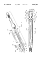
- FIG. 1 is an exploded perspective view of the bit and sonde housing of the present invention
- FIG. 2 is a top view of the bit and sonde housing of the present invention
- FIG. 3 is a top view of the bit of the present invention.
- FIG. 4 is a side top view of the bit and sonde housing of the present invention.
- FIG. 5 is an end view of the bit and sonde housing of the present invention.
- FIG. 6 is a section view taken along lines 6--6 of FIG. 4.
- the drilling system including the bit of the present invention is a system of horizontal directional drilling in rock.
- a drill head 100 includes specially-configured drill bit 102 at one end of a drill string 104 designed to intermittently rotate as it digs in, stops rotation until the rock fractures, and then moves after fracture in a random, orbital intermittent motion.
- the drill string 104 is rotated under pressure at a substantially constant rotational velocity at the other end of the drill string 104 by a conventional directional drilling machine.
- a fluid (not shown) may be pumped into the drill string and out the drill bit 102 to lubricate the hole and disperse cuttings.
- the specially-configured asymmetric drill bit 102 for horizontal directional drilling in rock includes a bit body 106 attached to an end 108 of a sonde housing 110.
- the bit body 106 is angled with respect to the sonde housing 110, as best shown in FIG. 6, with the angle displacement from collinear alignment being relatively slight, that is, on the order of about 15 degrees.
- the bit body 106 is mounted with three substantially forward-facing end studs 112 extending from a planar front face 114 (FIG. 5).
- a plurality of substantially radially-facing body studs 116 extend from a cylindrical side surface 118.
- the three forward-facing end studs 112 are slightly angled with respect to each other, as best shown in FIG. 5, with the longitudinal axis of the middle end stud 112 coplanar with the drill string and the other two angled outwardly, as shown.
- a plurality of chunk-protection studs 120 extend from an intersection edge 122 (FIG. 5) of the front face 114 and a concave steering face 124.
- Drill bit 102 has a concave steering channel 125 in substantially laterally-facing steering face 124 of the drill bit.
- asymmetric drill bit 102 and sonde housing 110 are joined by threaded fasteners 126 through unthreaded holes 128 in bit 102 and threaded holes 130 in sonde housing 110.
- a longitudinal shear relief structure between the drill bit and the sonde housing is also provided, to relieve fasteners 126 from substantially all shear loading.
- the shear relief structure is provided in the mating angled faces 132, 134 between the drill bit and the sonde housing (FIG. 6), and includes an upstanding shear relief rib 136 and a mating groove 138 in the mating angled faces 132 and 134, respectively.
- Rib 136 and groove 138 are longitudinally aligned with the mating angled faces 132, 134.
- groove 138 is in the sonde housing angled face 134 and the rib 136 is in the drill bit mating face 136.
- sonde housing 110 includes a cylindrical housing body 150 with walls 152 defining a longitudinal cavity 154.
- a cover 156 for the cavity 154 is attached to the body 150 by hold-down means for attaching the cover to the housing body.
- the directional earth boring tool system for boring all earth formations such as dirt, sand, rock and/or any type combination of formations, utilizes the bit body containing fixed and semi-floating cutting points and one or more fluid channels for the purpose of lubricating and dispersing cut and/or fractured formations.
- the high-impact point-fracturing method of removal of dense or rocky formations also creates a high-velocity orbital node while drilling softer or less dense formations.
- a key feature of the invention is that bit 102 stops and starts as it digs in and then fractures rock, then jumps to a new position. The rotational velocity of the bit intermittently goes to zero then jumps to new speed and then drops to zero again, while rotational velocity of the drill machine is relatively constant.
- the beveled cavity within the bit design allows the bit to be steerable in all formations.
- the bit body is attached to the boring drill body, which contains at least one or more fluid channels, by means of an interference connection that withstands transverse loading.
- the asymmetrical method of attachment incorporates resultant reactions from the drill stem and drill body derived from input torque and thrust supplied by the drilling machine, to create a random elliptical pattern while boring which also creates a hole larger than the concentric design of the drill body would typically allow.
- Drilling of hard rock formations is defined as a fracturing process as opposed to a cutting or shearing operations as used in conventional earth drilling applications. It is known that earth boring for horizontal directional drilling may be a combination of cutting or shearing and jetting.
- the jetting methods employ a system of high pressure, high velocity fluids with the specific purpose of making a suspension, or solution of earth formations and flowing these suspensions or solutions into the surrounding formations or out of the bore hole.
- Cutting or shearing systems use fluids to lubricate the drilling tools as well as carry off the spoils of drilling.
- Rock formations do not cut or shear well, and do not dissolve or contain binding components that are easily disassociated with water solvents or hydraulic forces of jetting.
- No current drilling bit and process combines the operational parameters of rock fracturing, and high included angle offsets for directional steering in soft earth formations.
- the new asymmetrical directional drilling point for rock and hard earth formations combines the techniques of point contact fracturing for rock with a high angle of attack for hard earth as well as soft formations. Fracturing is accomplished with application of hard carbide points on random elliptical torque vectors created as the asymmetrical geometry of the bit forms eccentric rotational paths by combination of rotation and thrust moments. Drilling of rock like shales that are typically considered to be compressed and extremely dense and dry clays are also enhanced by the aggressively pointed geometry of the drill bit.
- the asymmetrical geometry enhances the performance of the drill rack by multiplying the fracturing effect through leverage on the main drilling points.
- the offset drill points randomly fracture and engage as center points of rotation and multiply transverse moments 3 to 8 times the actual transverse moments that can be produced at the same diameter in a symmetrically formed fixed diameter drill bit.
- Bore hole size is defined and controlled by stabilizing the forward cutting points on a trailing shoe that contains replaceable, semipermanent carbide buttons that will fracture off irregular surfaces and help smooth the borehole as well as reduce the abrasive wear on the body of the bit.
- Rock or hard earth steering is accomplished by a partial rotation boring method. This method is applied by thrusting the bit into the bore face at a predefined rotational index position and rotating to a similarly defined end rotation position and then pullback. The procedure is then repeated as often as necessary to form the borehole into the desired amount of turn.
- the "steering channel” also reduces the frontal blank surface area greater than 50% resulting in less chances of "formation buildup.” This enhances push steering performance as well as eases the ability of drilling spoils to flow under the bit when straight boring.
- This drill bit does not use jetting or directed fluid application to enhance the performance of the drilling action. Drilling fluid is required to clean the drill bit and remove spoils from the bore hole. The drill bit will not generate high pressure during normal drilling applications.
- a unique shear relief structure is provided to reduce the loads on fasteners used to attach the rock bit to the sonde housing.
- the shear relief includes a longitudinal recessed groove, having a rectangular cross-section, and a matching raised tongue on the back side of the rock bit.
- the tongue extends substantially the entire length of the rock bit back side, for substantially complete engagement of the groove.
- the shear relief removes substantially all the shear load on the fasteners used to hold the rock bit to the sonde housing.
- the fasteners provide clamping pressure only, while the shear relief absorbs the enormous shear forces applied to the rock bit.
Abstract
Description
Claims (4)
Priority Applications (1)
| Application Number | Priority Date | Filing Date | Title |
|---|---|---|---|
| US08/968,485 US5931240A (en) | 1997-02-05 | 1997-11-12 | Drill bit concave steering channel for horizontal directional drilling |
Applications Claiming Priority (2)
| Application Number | Priority Date | Filing Date | Title |
|---|---|---|---|
| US4074797P | 1997-02-05 | 1997-02-05 | |
| US08/968,485 US5931240A (en) | 1997-02-05 | 1997-11-12 | Drill bit concave steering channel for horizontal directional drilling |
Publications (1)
| Publication Number | Publication Date |
|---|---|
| US5931240A true US5931240A (en) | 1999-08-03 |
Family
ID=21912714
Family Applications (3)
| Application Number | Title | Priority Date | Filing Date |
|---|---|---|---|
| US08/968,253 Expired - Lifetime US6209660B1 (en) | 1997-02-05 | 1997-11-12 | Drill bit shear relief for horizontal directional drilling of rock formations |
| US08/968,255 Expired - Lifetime US5934391A (en) | 1997-02-05 | 1997-11-12 | Sonde housing door hold-down system |
| US08/968,485 Expired - Lifetime US5931240A (en) | 1997-02-05 | 1997-11-12 | Drill bit concave steering channel for horizontal directional drilling |
Family Applications Before (2)
| Application Number | Title | Priority Date | Filing Date |
|---|---|---|---|
| US08/968,253 Expired - Lifetime US6209660B1 (en) | 1997-02-05 | 1997-11-12 | Drill bit shear relief for horizontal directional drilling of rock formations |
| US08/968,255 Expired - Lifetime US5934391A (en) | 1997-02-05 | 1997-11-12 | Sonde housing door hold-down system |
Country Status (4)
| Country | Link |
|---|---|
| US (3) | US6209660B1 (en) |
| CA (2) | CA2221069C (en) |
| IL (2) | IL123144A (en) |
| ZA (2) | ZA9710656B (en) |
Cited By (18)
| Publication number | Priority date | Publication date | Assignee | Title |
|---|---|---|---|---|
| WO2001049965A1 (en) * | 2000-01-04 | 2001-07-12 | Hunting Performance, Inc. | Integrated transmitter surveying while boring (swb) entrenching powering device for the continuation of a guided bore hole |
| US6390087B1 (en) * | 1998-08-24 | 2002-05-21 | Earth Tool Company. L.L.C. | Drill bit for directional drilling |
| US6470979B1 (en) | 1999-07-16 | 2002-10-29 | Earth Tool Company, L.L.C. | Sonde housing structure |
| US6789635B2 (en) | 2001-06-18 | 2004-09-14 | Earth Tool Company, L.L.C. | Drill bit for directional drilling in cobble formations |
| US6810971B1 (en) | 2002-02-08 | 2004-11-02 | Hard Rock Drilling & Fabrication, L.L.C. | Steerable horizontal subterranean drill bit |
| US6810972B2 (en) | 2002-02-08 | 2004-11-02 | Hard Rock Drilling & Fabrication, L.L.C. | Steerable horizontal subterranean drill bit having a one bolt attachment system |
| US6810973B2 (en) | 2002-02-08 | 2004-11-02 | Hard Rock Drilling & Fabrication, L.L.C. | Steerable horizontal subterranean drill bit having offset cutting tooth paths |
| US6814168B2 (en) | 2002-02-08 | 2004-11-09 | Hard Rock Drilling & Fabrication, L.L.C. | Steerable horizontal subterranean drill bit having elevated wear protector receptacles |
| US6827159B2 (en) | 2002-02-08 | 2004-12-07 | Hard Rock Drilling & Fabrication, L.L.C. | Steerable horizontal subterranean drill bit having an offset drilling fluid seal |
| US20090152012A1 (en) * | 2006-06-06 | 2009-06-18 | Vermer Manufacturing Company | Microtunnelling system and apparatus |
| US20100206637A1 (en) * | 2009-02-11 | 2010-08-19 | Harrison Stuart | Cutting Unit for a Tunneling Apparatus |
| US8939237B2 (en) | 2010-11-12 | 2015-01-27 | Vermeer Manufacturing Company | Underground drilling apparatus |
| US8955586B1 (en) * | 2011-01-24 | 2015-02-17 | Earth Tool Company, Llc | Beacon assembly |
| US20150233183A1 (en) * | 2014-02-14 | 2015-08-20 | Melfred Borzall, Inc. | Direct pullback devices and method of horizontal drilling |
| US9732560B2 (en) | 2013-08-29 | 2017-08-15 | Vermeer Manufacturing Company | Drilling tool and apparatus |
| US10024105B2 (en) * | 2015-02-25 | 2018-07-17 | Radius Hdd Direct, Llc | Rock bit |
| US11299977B2 (en) * | 2019-05-20 | 2022-04-12 | Halliburton Energy Services, Inc. | Recessed pockets for a drill collar |
| US11629556B2 (en) | 2018-02-23 | 2023-04-18 | Melfred Borzall, Inc. | Directional drill bit attachment tools and method |
Families Citing this family (17)
| Publication number | Priority date | Publication date | Assignee | Title |
|---|---|---|---|---|
| US6487901B1 (en) * | 1998-12-28 | 2002-12-03 | Robert C. Keyes | Transmitter housing for probe in a directional underground drilling apparatus |
| US6422782B1 (en) * | 1999-12-16 | 2002-07-23 | Earth Tool Company, L.L.C. | Apparatus for mounting an electronic device for use in directional drilling |
| JP5042428B2 (en) * | 2000-05-18 | 2012-10-03 | コモンウェルス サイエンティフィック アンド インダストリアル リサーチ オーガニゼイション | Cutting tool and method of use thereof |
| ATE354716T1 (en) | 2001-01-22 | 2007-03-15 | Vermeer Mfg Co | EXPANSION DEVICE |
| US6644421B1 (en) | 2001-12-26 | 2003-11-11 | Robbins Tools, Inc. | Sonde housing |
| US6918452B2 (en) * | 2002-12-17 | 2005-07-19 | Vetco Gray Inc. | Drill string shutoff valve |
| US7017682B2 (en) * | 2002-12-17 | 2006-03-28 | Vetco Gray Inc. | Drill string shutoff valve |
| US7367392B2 (en) * | 2004-01-08 | 2008-05-06 | Schlumberger Technology Corporation | Wellbore apparatus with sliding shields |
| US7364007B2 (en) * | 2004-01-08 | 2008-04-29 | Schlumberger Technology Corporation | Integrated acoustic transducer assembly |
| US7600582B2 (en) * | 2005-08-18 | 2009-10-13 | Texas Hdd, Llc | Sonde housing |
| US7654341B2 (en) * | 2006-10-26 | 2010-02-02 | Tt Technologies, Inc. | Drill stem coupling and method for a directional drill |
| US8364404B2 (en) * | 2008-02-06 | 2013-01-29 | Schlumberger Technology Corporation | System and method for displaying data associated with subsurface reservoirs |
| US7647989B2 (en) * | 2008-06-02 | 2010-01-19 | Vetco Gray Inc. | Backup safety flow control system for concentric drill string |
| CN104265165A (en) * | 2014-08-27 | 2015-01-07 | 桂林市华力重工机械有限责任公司 | Horizontal directional drilling machine cover |
| US10920573B1 (en) | 2019-10-18 | 2021-02-16 | Hunting Energy Services, Llc | Locking lid for downhole tools |
| CN112459706B (en) * | 2020-11-11 | 2022-09-02 | 中石化石油工程技术服务有限公司 | Method for identifying underground tripping drill by using air hammer triaxial vibration signal |
| PL442369A1 (en) | 2022-09-27 | 2024-04-02 | Akademia Górniczo-Hutnicza Im.Stanisława Staszica W Krakowie | Method of installing a modular underground water filter in a drilling hole and the underground water filter module |
Citations (12)
| Publication number | Priority date | Publication date | Assignee | Title |
|---|---|---|---|---|
| US2704204A (en) * | 1951-07-02 | 1955-03-15 | Pierce W Koontz | Drill bit for drilling over-size hole |
| US4867255A (en) * | 1988-05-20 | 1989-09-19 | Flowmole Corporation | Technique for steering a downhole hammer |
| US4989681A (en) * | 1988-06-10 | 1991-02-05 | Drebo Werkzeugfabrik Gmbh | Drill bit for producing undercuts |
| US5052503A (en) * | 1989-04-05 | 1991-10-01 | Uniroc Aktiebolag | Eccentric drilling tool |
| US5148875A (en) * | 1990-06-21 | 1992-09-22 | Baker Hughes Incorporated | Method and apparatus for horizontal drilling |
| US5148880A (en) * | 1990-08-31 | 1992-09-22 | The Charles Machine Works, Inc. | Apparatus for drilling a horizontal controlled borehole in the earth |
| US5163520A (en) * | 1991-01-28 | 1992-11-17 | Lag Steering Systems | Apparatus and method for steering a pipe jacking head |
| US5253721A (en) * | 1992-05-08 | 1993-10-19 | Straightline Manufacturing, Inc. | Directional boring head |
| US5392868A (en) * | 1993-05-25 | 1995-02-28 | The Charles Machine Works, Inc. | Directional multi-blade boring head |
| US5449046A (en) * | 1993-12-23 | 1995-09-12 | Electric Power Research Institute, Inc. | Earth boring tool with continuous rotation impulsed steering |
| US5469926A (en) * | 1994-04-22 | 1995-11-28 | Bor-Mor, Inc. | Directional boring drill bit blade |
| US5484029A (en) * | 1994-08-05 | 1996-01-16 | Schlumberger Technology Corporation | Steerable drilling tool and system |
Family Cites Families (2)
| Publication number | Priority date | Publication date | Assignee | Title |
|---|---|---|---|---|
| SE464145B (en) * | 1988-08-31 | 1991-03-11 | Diamant Boart Craelius Ab | DEVICE FOR TAKING HALES IN THE MARKET |
| CA2248024A1 (en) * | 1996-03-04 | 1997-09-12 | Vermeer Manufacturing Company | Directional boring |
-
1997
- 1997-11-12 US US08/968,253 patent/US6209660B1/en not_active Expired - Lifetime
- 1997-11-12 US US08/968,255 patent/US5934391A/en not_active Expired - Lifetime
- 1997-11-12 US US08/968,485 patent/US5931240A/en not_active Expired - Lifetime
- 1997-11-13 CA CA002221069A patent/CA2221069C/en not_active Expired - Fee Related
- 1997-11-13 CA CA002221068A patent/CA2221068C/en not_active Expired - Fee Related
- 1997-11-26 ZA ZA9710656A patent/ZA9710656B/en unknown
- 1997-11-26 ZA ZA9710658A patent/ZA9710658B/en unknown
-
1998
- 1998-02-02 IL IL12314498A patent/IL123144A/en not_active IP Right Cessation
- 1998-02-02 IL IL12314598A patent/IL123145A/en not_active IP Right Cessation
Patent Citations (12)
| Publication number | Priority date | Publication date | Assignee | Title |
|---|---|---|---|---|
| US2704204A (en) * | 1951-07-02 | 1955-03-15 | Pierce W Koontz | Drill bit for drilling over-size hole |
| US4867255A (en) * | 1988-05-20 | 1989-09-19 | Flowmole Corporation | Technique for steering a downhole hammer |
| US4989681A (en) * | 1988-06-10 | 1991-02-05 | Drebo Werkzeugfabrik Gmbh | Drill bit for producing undercuts |
| US5052503A (en) * | 1989-04-05 | 1991-10-01 | Uniroc Aktiebolag | Eccentric drilling tool |
| US5148875A (en) * | 1990-06-21 | 1992-09-22 | Baker Hughes Incorporated | Method and apparatus for horizontal drilling |
| US5148880A (en) * | 1990-08-31 | 1992-09-22 | The Charles Machine Works, Inc. | Apparatus for drilling a horizontal controlled borehole in the earth |
| US5163520A (en) * | 1991-01-28 | 1992-11-17 | Lag Steering Systems | Apparatus and method for steering a pipe jacking head |
| US5253721A (en) * | 1992-05-08 | 1993-10-19 | Straightline Manufacturing, Inc. | Directional boring head |
| US5392868A (en) * | 1993-05-25 | 1995-02-28 | The Charles Machine Works, Inc. | Directional multi-blade boring head |
| US5449046A (en) * | 1993-12-23 | 1995-09-12 | Electric Power Research Institute, Inc. | Earth boring tool with continuous rotation impulsed steering |
| US5469926A (en) * | 1994-04-22 | 1995-11-28 | Bor-Mor, Inc. | Directional boring drill bit blade |
| US5484029A (en) * | 1994-08-05 | 1996-01-16 | Schlumberger Technology Corporation | Steerable drilling tool and system |
Non-Patent Citations (4)
| Title |
|---|
| "Brochure for Barbco Directional Tooling", Barbco, Inc., Undated. |
| "Brochure for Straightline Directional Tooling--Training Seminar", Straightline Directional Drilling Systems, Jun. 14, 1996. |
| Brochure for Barbco Directional Tooling , Barbco, Inc., Undated. * |
| Brochure for Straightline Directional Tooling Training Seminar , Straightline Directional Drilling Systems, Jun. 14, 1996. * |
Cited By (31)
| Publication number | Priority date | Publication date | Assignee | Title |
|---|---|---|---|---|
| US6390087B1 (en) * | 1998-08-24 | 2002-05-21 | Earth Tool Company. L.L.C. | Drill bit for directional drilling |
| US6588515B2 (en) | 1998-08-24 | 2003-07-08 | Earth Tool Company, L.L.C. | Drill bit for directional drilling |
| US6470979B1 (en) | 1999-07-16 | 2002-10-29 | Earth Tool Company, L.L.C. | Sonde housing structure |
| WO2001049965A1 (en) * | 2000-01-04 | 2001-07-12 | Hunting Performance, Inc. | Integrated transmitter surveying while boring (swb) entrenching powering device for the continuation of a guided bore hole |
| US6349778B1 (en) * | 2000-01-04 | 2002-02-26 | Performance Boring Technologies, Inc. | Integrated transmitter surveying while boring entrenching powering device for the continuation of a guided bore hole |
| US6749030B2 (en) | 2000-01-04 | 2004-06-15 | Hunting Performance, Inc. | Integrated transmitter surveying while boring entrenching powering device for the continuation of a guided bore hole |
| US6789635B2 (en) | 2001-06-18 | 2004-09-14 | Earth Tool Company, L.L.C. | Drill bit for directional drilling in cobble formations |
| US6810971B1 (en) | 2002-02-08 | 2004-11-02 | Hard Rock Drilling & Fabrication, L.L.C. | Steerable horizontal subterranean drill bit |
| US6810972B2 (en) | 2002-02-08 | 2004-11-02 | Hard Rock Drilling & Fabrication, L.L.C. | Steerable horizontal subterranean drill bit having a one bolt attachment system |
| US6810973B2 (en) | 2002-02-08 | 2004-11-02 | Hard Rock Drilling & Fabrication, L.L.C. | Steerable horizontal subterranean drill bit having offset cutting tooth paths |
| US6814168B2 (en) | 2002-02-08 | 2004-11-09 | Hard Rock Drilling & Fabrication, L.L.C. | Steerable horizontal subterranean drill bit having elevated wear protector receptacles |
| US6827159B2 (en) | 2002-02-08 | 2004-12-07 | Hard Rock Drilling & Fabrication, L.L.C. | Steerable horizontal subterranean drill bit having an offset drilling fluid seal |
| US20090152012A1 (en) * | 2006-06-06 | 2009-06-18 | Vermer Manufacturing Company | Microtunnelling system and apparatus |
| US8439132B2 (en) | 2006-06-16 | 2013-05-14 | Vermeer Manufacturing Company | Microtunnelling system and apparatus |
| US7942217B2 (en) | 2006-06-16 | 2011-05-17 | Vermeer Manufacturing Company | Cutting apparatus for a microtunnelling system |
| US20100206636A1 (en) * | 2009-02-11 | 2010-08-19 | Harrison Stuart | Backreamer for a Tunneling Apparatus |
| US20100230171A1 (en) * | 2009-02-11 | 2010-09-16 | Harrison Stuart | Drill Head for a Tunneling Apparatus |
| US20100206635A1 (en) * | 2009-02-11 | 2010-08-19 | Harrison Stuart | Tunneling Apparatus Including Vacuum and Method of Use |
| US8256536B2 (en) | 2009-02-11 | 2012-09-04 | Vermeer Manufacturing Company | Backreamer for a tunneling apparatus |
| US20100206637A1 (en) * | 2009-02-11 | 2010-08-19 | Harrison Stuart | Cutting Unit for a Tunneling Apparatus |
| US8439450B2 (en) | 2009-02-11 | 2013-05-14 | Vermeer Manufacturing Company | Tunneling apparatus including vacuum and method of use |
| US8684470B2 (en) | 2009-02-11 | 2014-04-01 | Vermeer Manufacturing Company | Drill head for a tunneling apparatus |
| US8939237B2 (en) | 2010-11-12 | 2015-01-27 | Vermeer Manufacturing Company | Underground drilling apparatus |
| US8955586B1 (en) * | 2011-01-24 | 2015-02-17 | Earth Tool Company, Llc | Beacon assembly |
| US9732560B2 (en) | 2013-08-29 | 2017-08-15 | Vermeer Manufacturing Company | Drilling tool and apparatus |
| US20150233183A1 (en) * | 2014-02-14 | 2015-08-20 | Melfred Borzall, Inc. | Direct pullback devices and method of horizontal drilling |
| US9719344B2 (en) * | 2014-02-14 | 2017-08-01 | Melfred Borzall, Inc. | Direct pullback devices and method of horizontal drilling |
| US10246993B2 (en) * | 2014-02-14 | 2019-04-02 | Melfred Borzall, Inc. | Direct pullback devices and method of horizontal drilling |
| US10024105B2 (en) * | 2015-02-25 | 2018-07-17 | Radius Hdd Direct, Llc | Rock bit |
| US11629556B2 (en) | 2018-02-23 | 2023-04-18 | Melfred Borzall, Inc. | Directional drill bit attachment tools and method |
| US11299977B2 (en) * | 2019-05-20 | 2022-04-12 | Halliburton Energy Services, Inc. | Recessed pockets for a drill collar |
Also Published As
| Publication number | Publication date |
|---|---|
| US5934391A (en) | 1999-08-10 |
| CA2221068C (en) | 2001-07-24 |
| IL123144A (en) | 2001-09-13 |
| CA2221069A1 (en) | 1998-08-05 |
| IL123145A0 (en) | 1998-09-24 |
| ZA9710658B (en) | 1998-09-07 |
| US6209660B1 (en) | 2001-04-03 |
| ZA9710656B (en) | 1998-09-08 |
| CA2221069C (en) | 2001-07-24 |
| CA2221068A1 (en) | 1998-08-05 |
| IL123145A (en) | 2001-05-20 |
| IL123144A0 (en) | 1998-09-24 |
Similar Documents
| Publication | Publication Date | Title |
|---|---|---|
| US5950743A (en) | Method for horizontal directional drilling of rock formations | |
| US5931240A (en) | Drill bit concave steering channel for horizontal directional drilling | |
| US5899283A (en) | Drill bit for horizontal directional drilling of rock formations | |
| US6450269B1 (en) | Method and bit for directional horizontal boring | |
| US4679637A (en) | Apparatus and method for forming an enlarged underground arcuate bore and installing a conduit therein | |
| US5253721A (en) | Directional boring head | |
| US4784230A (en) | Apparatus and method for installing a conduit within an arcuate bore | |
| US4993503A (en) | Horizontal boring apparatus and method | |
| AU2001288875A1 (en) | Method and bit for directional horizontal boring | |
| US6109371A (en) | Method and apparatus for steering an earth boring tool | |
| USRE33793E (en) | Apparatus and method for forming an enlarged underground arcuate bore and installing a conduit therein | |
| US4540056A (en) | Cutter assembly | |
| CN102232138B (en) | Anti-whirl drill bits, wellsite systems, and methods of using the same | |
| US10024105B2 (en) | Rock bit | |
| KR100188482B1 (en) | Drill head with nozzles | |
| CA2527385C (en) | Directional drill head | |
| MXPA98000795A (en) | Method for drilling with controlled horizontal direction of r-formations | |
| JP7032152B2 (en) | Bit for drilling | |
| RU2215110C2 (en) | Drilling complex for laying service lines | |
| CA3154670A1 (en) | Drill assembly and method of using same |
Legal Events
| Date | Code | Title | Description |
|---|---|---|---|
| AS | Assignment |
Owner name: RAILHEAD UNDERGROUND PRODUCTS, LLC, TEXAS Free format text: ASSIGNMENT OF ASSIGNORS INTEREST;ASSIGNOR:COX, DAVID M.;REEL/FRAME:009067/0639 Effective date: 19971107 |
|
| AS | Assignment |
Owner name: NEW RAILHEAD MANUFACTURING, L.L.C., TEXAS Free format text: NUNC PRO TUNC ASSIGNMENT;ASSIGNOR:COX, DAVID M.;REEL/FRAME:009964/0262 Effective date: 19990507 |
|
| REMI | Maintenance fee reminder mailed | ||
| REIN | Reinstatement after maintenance fee payment confirmed | ||
| FP | Lapsed due to failure to pay maintenance fee |
Effective date: 20030803 |
|
| FEPP | Fee payment procedure |
Free format text: PETITION RELATED TO MAINTENANCE FEES FILED (ORIGINAL EVENT CODE: PMFP); ENTITY STATUS OF PATENT OWNER: SMALL ENTITY |
|
| FPAY | Fee payment |
Year of fee payment: 4 |
|
| SULP | Surcharge for late payment | ||
| PRDP | Patent reinstated due to the acceptance of a late maintenance fee |
Effective date: 20040223 |
|
| STCF | Information on status: patent grant |
Free format text: PATENTED CASE |
|
| FPAY | Fee payment |
Year of fee payment: 8 |
|
| FPAY | Fee payment |
Year of fee payment: 12 |