US5936795A - Magazine cassette locking device - Google Patents
Magazine cassette locking device Download PDFInfo
- Publication number
- US5936795A US5936795A US08/811,677 US81167797A US5936795A US 5936795 A US5936795 A US 5936795A US 81167797 A US81167797 A US 81167797A US 5936795 A US5936795 A US 5936795A
- Authority
- US
- United States
- Prior art keywords
- cassette
- magazine
- locking device
- cassettes
- column
- Prior art date
- Legal status (The legal status is an assumption and is not a legal conclusion. Google has not performed a legal analysis and makes no representation as to the accuracy of the status listed.)
- Expired - Lifetime
Links
Images


Classifications
-
- G—PHYSICS
- G11—INFORMATION STORAGE
- G11B—INFORMATION STORAGE BASED ON RELATIVE MOVEMENT BETWEEN RECORD CARRIER AND TRANSDUCER
- G11B15/00—Driving, starting or stopping record carriers of filamentary or web form; Driving both such record carriers and heads; Guiding such record carriers or containers therefor; Control thereof; Control of operating function
- G11B15/675—Guiding containers, e.g. loading, ejecting cassettes
- G11B15/68—Automatic cassette changing arrangements; automatic tape changing arrangements
- G11B15/6805—Automatic cassette changing arrangements; automatic tape changing arrangements with linearly moving rectangular box shaped magazines
- G11B15/681—Automatic cassette changing arrangements; automatic tape changing arrangements with linearly moving rectangular box shaped magazines in vertical direction
-
- G—PHYSICS
- G11—INFORMATION STORAGE
- G11B—INFORMATION STORAGE BASED ON RELATIVE MOVEMENT BETWEEN RECORD CARRIER AND TRANSDUCER
- G11B17/00—Guiding record carriers not specifically of filamentary or web form, or of supports therefor
- G11B17/22—Guiding record carriers not specifically of filamentary or web form, or of supports therefor from random access magazine of disc records
- G11B17/225—Guiding record carriers not specifically of filamentary or web form, or of supports therefor from random access magazine of disc records wherein the disks are transferred from a fixed magazine to a fixed playing unit using a moving carriage
-
- G—PHYSICS
- G11—INFORMATION STORAGE
- G11B—INFORMATION STORAGE BASED ON RELATIVE MOVEMENT BETWEEN RECORD CARRIER AND TRANSDUCER
- G11B17/00—Guiding record carriers not specifically of filamentary or web form, or of supports therefor
- G11B17/22—Guiding record carriers not specifically of filamentary or web form, or of supports therefor from random access magazine of disc records
- G11B17/26—Guiding record carriers not specifically of filamentary or web form, or of supports therefor from random access magazine of disc records the magazine having a cylindrical shape with vertical axis
Definitions
- the present invention relates to a cassette loading assembly for loading a plurality of tape cassettes into a tape drive, and more particularly, to a device for positive restraint of a cassette within a magazine of the tape loading assembly, which device may be disengaged to allow loading of the cassette from the magazine to the tape drive.
- DAT digital audio tape
- R-DAT tape cassettes for 51/4 inch form factor tape drives can store up to approximately 5 to 10 gigabytes of data.
- many applications including archival storage, journaling, on-line and background storage, and the unattended back-up of large amounts of data, may require storage of several times that amount of data.
- backing up a data source of more than 10 gigabytes it is necessary to frequently change the cassette tape in a cassette drive, generally about once every few hours. Since most such backing up is done outside of normal work hours to avoid tying up the computer holding the data, it is often not convenient to change the data tape.
- cassette loading systems which are capable of holding a plurality of data tape cassettes for loading automatically into a tape drive.
- the system includes a storage magazine comprising a plurality of cassette bays where the tapes are held for loading into the tape drive, and a loader which accomplishes the transfer of the cassette tapes from the cassette bays into the drive.
- An example of such a tape loading system has been developed by Predator Systems Corporation under the name Data Hawk I, which holds up to eight, 4 mm DAT cassettes for loading and unloading to a 4 mm DAT cassette drive.
- a disadvantage to conventional cassette magazines is that the cassette tapes may be dislodged from the cassette bays if the magazine is mishandled. Moreover, when the magazine is in operation with a tape drive, a shock to the magazine or the drive may cause one or more of the cassette tapes to become partially or completely dislodged, thereby potentially causing errors or shut-down of an unattended system.
- the present invention relates to a device for positively restraining data tape cassettes within a magazine to prevent the cassettes from becoming dislodged from the magazine when the cassettes are not engaged within the tape drive.
- the device includes a spring loaded cantilever having an end section which engages a detent conventionally formed in the rear portion of a side of a data cassette tape. When the cantilever end section is engaged in the detent, the cassette is securely held against a rear interior wall of the magazine.
- the cantilever further includes a load-receiving end opposite the end section.
- a force exerted on the load-receiving end of the cantilever will bias the end section out of the detent in the cassette, to thereby allow the cassette to be removed from the cassette bay.
- a cassette will remain locked within a cassette bay unless the end section of the cantilever is manually biased out of the detent, or when the cassette is to be loaded into a tape drive by the cassette loading assembly as explained below.
- the cassette loading assembly includes a cassette transfer assembly for loading a cassette from the magazine into the tape drive.
- Rotating pinch rollers are provided as part of the transfer assembly on opposite sides of a cassette loader to load a tape from the magazine into the tape drive.
- the transfer assembly moves the pinch rollers inward to engage the sides of a cassette tape. Once in contact with the cassette, the pinch rollers rotate against the sides of the cassette tape to urge the tape into the tape drive slot.
- the transfer assembly further includes a bracket mounted adjacent to a pinch roller on one or both sides of the magazine.
- the bracket moves with the pinch roller so that, as the pinch roller is swung inward from a side of the magazine, the bracket engages the load-receiving end of the cantilever to thereby pivot the opposite end section of the cantilever out of the detent.
- the cassette tape is freely loaded into the tape drive by the pinch rollers against the sides of the cassette tape.
- the bracket remains in contact with the load-receiving end of the cantilever while the cassette is in the tape drive.
- the pinch rollers When a cassette tape is removed from the drive, the pinch rollers, rotating in an opposite direction than for cassette insertion, bias the cassette out of the drive. Once the cassette is restored to the magazine, the transfer assembly swings the pinch rollers away from the sides of the cassette, and the bracket is moved away from the load-receiving end of the cantilever. The end section of the spring loaded cantilever is thereupon biased to once again engage the cassette detent.
- Each cassette bay in the magazine is provided with one or two locking devices according to the present invention.
- the locking device in one cassette bay is disengaged to load the cassette tape contained therein into the tape drive, the remainder of the cassettes in the magazine are restrained within their respective cassette bays.
- the magazine may include means for allowing only one cassette to be dislodged at a given time.
- a column is provided within each cassette bay and extending the entire length of the magazine.
- the column is hollow, with a plurality of slots, one slot for each cassette bay in the magazine.
- the slots are sized and provided with respect to the cassette locking devices such that, when an end section of a cantilever is pivoted out of a detent, an extension fixedly provided on the end section is received through a corresponding slot and into the interior of the column.
- the column is filled with a single row of ball bearings. There is enough space within the interior of the column for any pair of ball bearings to separate a sufficient distance to accept an extension on the cantilever therebetween. However, the combined height of the ball bearings within the sealed column is such that, when one extension is in the column between a pair of ball bearings, there is insufficient space for a second pair of ball bearings to separate to accept a second extension into the interior. Thus, only one extension may be received within the column at a given time. An extension enters the column as result of a cantilever pivoting the end section out of the cassette detent.
- the cantilever end section will not fully pivot out of the detent in which it is engaged, and the cassette will remain locked in the magazine.
- only one cassette for example the cassette loaded within the tape drive, may be removed from the magazine at a given time.
- the column may be removed from the magazine to change or otherwise remove as many cassettes as is desired.
- FIG. 1a is a perspective view of a tape drive loading mechanism operating with a tape drive
- FIG. 1b is a side view of the tape drive loading mechanism shown in FIG. 1a;
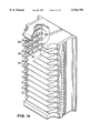
- FIG. 1c is a cut-away perspective view of a magazine including the locking device of the present invention.
- FIG. 2 is a cross-sectional top view through line 2--2 of FIG. 1a showing the locking device of the present invention
- FIG. 3 is a cross-sectional side view through line 3--3 of FIG. 1a showing the locking device of the present invention
- FIG. 4 is a side view of a cantilever according to the present invention.
- FIG. 5 is a top view of a cantilever according to the present invention.
- FIG. 5a is a perspective view of the cantilever shown in FIGS. 4 and 5.
- FIG. 6 is a top view of a cassette bay including a cassette tape and pinch rollers for loading the cassette into a tape drive;
- FIG. 7 is an enlarged top view of the present invention shown in the unlocked position
- FIG. 8 is an enlarged top view of the present invention shown in the locked position
- FIG. 9 is a side view of the present invention including a column for locking the cassettes within the magazine;
- FIG. 10a is a side view of the column according to the present invention.
- FIG. 10b is a front view of the column according to the present invention.
- FIG. 11a shows a side view of cantilever according to the present invention including an extension
- FIG. 11b shows a top view of cantilever according to the present invention including an extension
- FIG. 11c is a perspective view of the cantilever shown in FIGS. 11a and 11b.
- FIGS. 1-11c generally disclose a locking device for positive restraint of a cassette tape within a magazine of a cassette loading assembly. It is understood that the locking device according to the present invention may operate with cassette tapes and cassette loading assemblies of various known sizes and configurations.
- Cassette loading assemblies are well known in the art for loading a plurality of cassette tapes into a tape drive.
- One such device is disclosed in U.S. Pat. No. 5,264,974 entitled CASSETTE LOADING SYSTEM by Theobald et al., which application is assigned to the owner of the present invention and incorporated herein by reference.
- a cassette loading assembly as in U.S. Pat. No. 5,264,974 includes a magazine 20 translationally mounted for vertical movement within a loader 22.
- Loader 22 is mounted adjacent to a drive slot of tape drive 24.
- magazine 20 includes a plurality of cassette bays 27, each for housing a cassette 26.
- magazine 20 preferably has four cassette bays 27.
- the magazine 20 may have twelve cassette bays 27. It is understood, however, that the magazine may include more or less than four or twelve cassette bays.
- a cassette bay 27 includes an open forward end facing the tape drive 24, a rear face opposed to the forward end, and a pair of spaced apart side walls extending between the forward end and the rear face.
- the cassette bay 27 is provided with a size so that a conventional DAT cassette for a 51/4 inch form factor tape drive fits snugly therein. It is understood, however, that the present invention may operate in cassette bays formed to various sizes to accept cassette tapes of various form factors and configurations.
- FIG. 2 illustrates a cross-sectional top view through line 2--2 of FIG. 1a through one of the cassette bays 27, and FIG. 3 illustrates a cross-sectional side view through line 3--3 of FIG. 1a.
- a locking device according to the present invention is shown generally at 28, disposed adjacent to opposite side walls of the cassette bay 27.
- each cassette bay 27 includes two locking devices.
- the present invention may alternatively operate with one cassette locking device in either side wall.
- the cassette locking devices in opposite side walls are identical to each other, and for convenience, discussion hereinafter refers to only a single cassette locking device.
- the locking device 28 is comprised of a cantilever 30 pivotally mounted at the side wall by a shaft 32 (FIG. 3).
- Shaft 32 extends the entire length of magazine 20 through each cassette bay 27 to mount each of the cassette locking devices to the side wall.
- a force exerted in the direction of arrow A at load-receiving end 34 of cantilever 30 will cause a corresponding movement in the direction of arrow B at opposite end section 36.
- cantilever 30 is biased by a spring 38 so that end section 36 is urged against cassette 26 into a detent 40 conventionally formed in both side edges of the cassette 26. In such a position, cassette 26 is positively restrained within the magazine cassette bay 27 against a rear face 42 of the cassette bay.
- Cassette 26 will remain locked within the cassette bay 27 until a force acts on cantilever 30 to remove end section 36 from detent 40.
- both cantilevers 30 must be disengaged as described above to free the cassette 26 from its cassette bay 27.
- cassette locking device 28 is comprised of cantilever 30 and spring 38.
- Cantilever 30 (FIGS. 4-5a) preferably includes load-receiving end 34 and end section 36 opposite thereto.
- Cantilever 30 is further provided with a hole 44 between load-receiving end 34 and end section 36 for receiving shaft 32 to thereby pivotally mount cantilever 30 within the cassette bay 27.
- End section 36 of cantilever 30 may include a tab 46 extending generally perpendicular to the length of the cantilever. Tab 46 is received within detent 40 to restrain the cassette 26 within bay 27.
- Cantilever 30 may be alternatively formed without tab 46.
- the end section 36 may be angled with respect to the remainder of cantilever 30 for receipt within detent 40. It is understood that cantilever 30 may be formed to various known constructions at the side wall of the cassette bay 27 to latch cassette 26 within bay 27.
- the cassette loading device includes an LED and phototransistor sensor assembly (not shown) mounted within the side of each cassette bay 27.
- the LED/sensor assembly is responsible for detecting the presence of a cassette 26 within a cassette bay 27.
- the cantilever 30 may preferably be formed of a transparent polycarbonate such as that manufactured by General Electric Corp., Pittsfield, Mass. 01201. Light from the LED is therefore able to pass through the cantilever 30 relatively unobstructed. It will be understood by those in the art that the sensor design may be modified and that cantilever 30 may be formed from other rigid, durable materials such as, for example, aluminum or a high strength polymer.
- spring 38 may be a torsional spring as shown in FIGS. 7 and 8.
- Spring 38 imparts a force on cantilever 30 in the direction of arrow C (FIG. 7), to thereby bias end section 36 into detent 40.
- FIGS. 7 and 8 Spring 38 imparts a force on cantilever 30 in the direction of arrow C (FIG. 7), to thereby bias end section 36 into detent 40.
- a cassette 26 will remain locked within a cassette bay 27 by cassette locking device 28 unless the end section 36 of the cantilever is manually biased out of the detent 40, or when a cassette 26 is to be loaded into a tape drive 24 by the cassette loading assembly.
- Cassette locking device 28 may be disengaged for loading of a cassette 26 into drive 24 as follows.
- the cassette loading assembly includes a cassette transfer assembly 53 (shown partially on FIGS. 7 and 8) for loading a cassette from the magazine into the tape drive.
- the magazine is vertically positioned so that a desired cassette within the magazine is aligned with the tape drive slot.
- the cassette transfer assembly 53 includes rotating pinch rollers 52 on opposite sides of the cassette bay 27, on either side of the cassette 26 to be loaded. To load a cassette, the transfer assembly 53 swings the pinch rollers inward to engage the cassette tape. Once in contact with the cassette, the pinch rollers 52 rotate against the sides of the cassette tape 26 to urge the tape into the tape drive slot.
- the transfer assembly 53 further includes a bracket 54 mounted adjacent to one pinch roller 52 on each side of the cassette. While only one pinch roller and bracket are shown in FIGS. 7 and 8, it is understood that there is a second pinch roller and bracket not shown, on the opposite side of cassette bay 27.
- the pinch roller and bracket not shown are identical to and the mirror image of pinch roller 52 and bracket 54 of FIGS. 7 and 8.
- bracket 54 engages load-receiving end 34 of cantilever 30.
- bracket 54 exerts a force on load-receiving end 34 in the direction of arrow A (FIG.
- the pinch rollers 52 When a cassette tape is removed from the drive, the pinch rollers 52, rotating in an opposite direction than for cassette insertion, contact the sides of the cassette tape 26 to bias the cassette out of the drive 24. Once the cassette tape is completely restored within the magazine 20, the cassette transfer assembly 53 swings rollers 52 and bracket 54 back toward the side walls of the cassette bay, thereby releasing load-receiving end 34. The tab 46 is thereupon biased into detent 40 by spring 38 to once again positively restrain the cassette 26 within the magazine 20.
- Each cassette bay 27 in magazine 20 preferably includes one or two cassette locking devices 28 according to the present invention.
- bracket(s) 54 are acting on particular locking device(s) 28 to release the corresponding cassette 26 for loading into drive 24, the remaining cassettes in magazine 20 remain locked within magazine 20.
- a plurality of cassettes 26 may be removed from magazine 20 at a given time, provided each of the cassette locking devices 28 associated with the plurality of cassettes 26 are first disengaged.
- the present invention may include a lock control device which allows only one cantilever 30 within magazine 20 to be pivoted out of detent 40 at a given time, thereby locking all cassettes except one within the magazine 20.
- FIGS. 9-11c show a cassette loading assembly as described above and further including a column 56 extending from the top to the bottom of the magazine 20.
- Column 56 may preferably be a hollow tube closed at the top and bottom, with a plurality of slots 58 formed along its length.
- a plurality of ball bearings 60 are provided within the interior of column 56.
- the diameter of each spherical ball bearing 60 is preferably about 0.113 inches and the inner diameter of the column is preferably about 0.118 inches.
- the ball bearings 60 fit snugly within column 56, substantially in a straight line, one on top of another, along the length of the column.
- the height of the interior portion of column 56 is substantially 5.241 inches, and the combined height of all the bearings 60 within the column 56 is substantially 5.200 inches.
- a gap of at most 0.041 inches may separate any two adjoining bearings. It is important to note that if any two adjoining bearings are separated by this maximum distance of 0.041 inches, substantially no other gaps may be formed between any other pair of adjoining bearings within column 56.
- the height and inner diameter of the column 56 may vary and still be within the scope of the invention.
- the number and diameter of the ball bearings 60 within the column 56 may vary depending on the height of the column 56.
- each cantilever 30 may additionally include an extension 62 formed on the cantilever end section 36 adjacent to tab 46.
- Extension 62 may have a thickness of substantially 0.030 inches.
- column 56 is fixedly provided within magazine 20 and the slots 58 are provided with respect to cantilevers 30 such that each slot 58 is aligned to receive one of the extensions 62 when end section 36 is pivoted out of the detent 40.
- extension 62 of the second cassette locking device When an end section 36 of a particular cantilever 30 is pivoted away from a detent 40, as explained with reference to FIGS. 6-8 above, the extension on that cantilever is received through the aligned slot 58 and into the interior of column 56. If no other extension 62 from another cassette locking device of the magazine is located within the column 56, extension 62 wedges between a pair of adjoining ball bearings 60. The pair of ball bearings may separate a sufficient amount to accommodate the extension due to the difference in the height of the interior of the column and the combined height of all the bearings together. However, once one extension 62 is located within column 56, there is not sufficient room within the column of ball bearings to accommodate a second extension therebetween. Thus, only one extension may be received within column 56 at a given time. If an attempt is made to dislodge a second cassette by pivoting end section 36 of a second cassette locking device out of a detent 40, the extension 62 of the second cassette locking device will be prevented from entering the column 56.
- Detent 40 is conventionally formed approximately 0.050 inches deep. Therefore, end section 36 must travel a linear distance of at least 0.055 inches in order to clear tab 46 out of detent 40.
- end section 36 When an extension 62 is properly located within the column 56 between a pair of ball bearings, the end section has traveled a linear distance of approximately 0.060 inches, and thus, the tab 46 is free of the detent 40 and the associated cassette 24 may be dislodged from the magazine 20.
- an extension of a cantilever 30 is prevented from entering the column 56 (i.e., another extension 56 is already located within the column), then the maximum linear distance the end section of that cantilever may pivot is 0.015 inches.
Abstract
Description
Claims (12)
Priority Applications (1)
| Application Number | Priority Date | Filing Date | Title |
|---|---|---|---|
| US08/811,677 US5936795A (en) | 1997-03-05 | 1997-03-05 | Magazine cassette locking device |
Applications Claiming Priority (1)
| Application Number | Priority Date | Filing Date | Title |
|---|---|---|---|
| US08/811,677 US5936795A (en) | 1997-03-05 | 1997-03-05 | Magazine cassette locking device |
Publications (1)
| Publication Number | Publication Date |
|---|---|
| US5936795A true US5936795A (en) | 1999-08-10 |
Family
ID=25207232
Family Applications (1)
| Application Number | Title | Priority Date | Filing Date |
|---|---|---|---|
| US08/811,677 Expired - Lifetime US5936795A (en) | 1997-03-05 | 1997-03-05 | Magazine cassette locking device |
Country Status (1)
| Country | Link |
|---|---|
| US (1) | US5936795A (en) |
Cited By (13)
| Publication number | Priority date | Publication date | Assignee | Title |
|---|---|---|---|---|
| US6042205A (en) * | 1999-05-25 | 2000-03-28 | Hewlett-Packard Company | Media holding device incorporating a media locking mechanism |
| WO2001009887A1 (en) * | 1999-07-28 | 2001-02-08 | Storage Technology Corporation | Array and method for standardizing cartridge location within storage cells of a data storage library |
| US6396656B1 (en) * | 1998-12-17 | 2002-05-28 | Nec Corporation | Wrong insertion prevention device for cartridge type recording medium |
| US6425723B1 (en) * | 1999-08-04 | 2002-07-30 | Fujitsu Limited | Loading device |
| US6480443B1 (en) * | 2000-04-14 | 2002-11-12 | Hewlett-Packard Co. | Method and system for restraining a cartridge within an insertable magazine |
| US6560061B2 (en) * | 2001-01-04 | 2003-05-06 | Qualstar Corporation | High density tape library system |
| US6771448B2 (en) * | 2002-01-04 | 2004-08-03 | International Business Machines Corporation | Tension/compression compliant link for cartridge loading apparatus |
| EP1622147A2 (en) * | 2004-07-30 | 2006-02-01 | Tandberg Data ASA | Magnetic tape cartridge storage apparatus with lock and release device |
| US20060231513A1 (en) * | 2005-04-13 | 2006-10-19 | Quantum Corporation | Universal housing for holding storage devices |
| US7580220B1 (en) * | 2005-07-18 | 2009-08-25 | Storage Technology Corporation | Cartridge magazine with pivoting cartridge retention mechanism |
| US20110000863A1 (en) * | 2008-03-05 | 2011-01-06 | Venture Corporation Limited | Tape Storage Slot |
| US20170301374A1 (en) * | 2016-04-15 | 2017-10-19 | International Business Machines Corporation | Positive latching of tape cartridges in tape library magazines |
| US11574656B2 (en) * | 2020-02-13 | 2023-02-07 | International Business Machines Corporation | Automated tape library deep slot protection |
Citations (8)
| Publication number | Priority date | Publication date | Assignee | Title |
|---|---|---|---|---|
| JPH0281352A (en) * | 1988-09-19 | 1990-03-22 | Hitachi Ltd | Cartridge magnetic tape library device |
| US5021902A (en) * | 1988-02-17 | 1991-06-04 | Hitachi, Ltd. | Tape changer for loading and unloading a magazine of magnetic tape cartridges |
| JPH0512821A (en) * | 1991-07-04 | 1993-01-22 | Hitachi Ltd | Cartridge magazine |
| US5182687A (en) * | 1989-11-09 | 1993-01-26 | Archive Corporation | Method and apparatus for aligning cartridges with a cartridge insertion slot |
| US5264974A (en) * | 1991-09-30 | 1993-11-23 | Campbell Kenneth C | Cassette loading system |
| JPH06309765A (en) * | 1993-04-23 | 1994-11-04 | Victor Co Of Japan Ltd | Md changer device |
| US5402285A (en) * | 1991-09-30 | 1995-03-28 | Conner Peripherals, Inc. | Five and one-quarter inch form factor combination DAT tape drive and cassette magazine loader |
| US5537268A (en) * | 1994-11-14 | 1996-07-16 | International Business Machine Corporation | Multi-function locking mechanism for a multi-celled data cassette magazine |
-
1997
- 1997-03-05 US US08/811,677 patent/US5936795A/en not_active Expired - Lifetime
Patent Citations (8)
| Publication number | Priority date | Publication date | Assignee | Title |
|---|---|---|---|---|
| US5021902A (en) * | 1988-02-17 | 1991-06-04 | Hitachi, Ltd. | Tape changer for loading and unloading a magazine of magnetic tape cartridges |
| JPH0281352A (en) * | 1988-09-19 | 1990-03-22 | Hitachi Ltd | Cartridge magnetic tape library device |
| US5182687A (en) * | 1989-11-09 | 1993-01-26 | Archive Corporation | Method and apparatus for aligning cartridges with a cartridge insertion slot |
| JPH0512821A (en) * | 1991-07-04 | 1993-01-22 | Hitachi Ltd | Cartridge magazine |
| US5264974A (en) * | 1991-09-30 | 1993-11-23 | Campbell Kenneth C | Cassette loading system |
| US5402285A (en) * | 1991-09-30 | 1995-03-28 | Conner Peripherals, Inc. | Five and one-quarter inch form factor combination DAT tape drive and cassette magazine loader |
| JPH06309765A (en) * | 1993-04-23 | 1994-11-04 | Victor Co Of Japan Ltd | Md changer device |
| US5537268A (en) * | 1994-11-14 | 1996-07-16 | International Business Machine Corporation | Multi-function locking mechanism for a multi-celled data cassette magazine |
Cited By (18)
| Publication number | Priority date | Publication date | Assignee | Title |
|---|---|---|---|---|
| US6396656B1 (en) * | 1998-12-17 | 2002-05-28 | Nec Corporation | Wrong insertion prevention device for cartridge type recording medium |
| US6042205A (en) * | 1999-05-25 | 2000-03-28 | Hewlett-Packard Company | Media holding device incorporating a media locking mechanism |
| WO2001009887A1 (en) * | 1999-07-28 | 2001-02-08 | Storage Technology Corporation | Array and method for standardizing cartridge location within storage cells of a data storage library |
| US6244677B1 (en) | 1999-07-28 | 2001-06-12 | Storage Technology Corporation | Array and method for standardizing cartridge location within storage cells of a data storage library |
| US6425723B1 (en) * | 1999-08-04 | 2002-07-30 | Fujitsu Limited | Loading device |
| US6480443B1 (en) * | 2000-04-14 | 2002-11-12 | Hewlett-Packard Co. | Method and system for restraining a cartridge within an insertable magazine |
| US6560061B2 (en) * | 2001-01-04 | 2003-05-06 | Qualstar Corporation | High density tape library system |
| US6771448B2 (en) * | 2002-01-04 | 2004-08-03 | International Business Machines Corporation | Tension/compression compliant link for cartridge loading apparatus |
| EP1622147A2 (en) * | 2004-07-30 | 2006-02-01 | Tandberg Data ASA | Magnetic tape cartridge storage apparatus with lock and release device |
| EP1622147A3 (en) * | 2004-07-30 | 2008-03-05 | Tandberg Data ASA | Magnetic tape cartridge storage apparatus with lock and release device |
| CN1728267B (en) * | 2004-07-30 | 2011-03-30 | 坦德伯格数据有限公司 | Magnetic tape cartridge storage apparatus with lock and release device |
| US20060231513A1 (en) * | 2005-04-13 | 2006-10-19 | Quantum Corporation | Universal housing for holding storage devices |
| US7486473B2 (en) * | 2005-04-13 | 2009-02-03 | Quantum Corporation | Universal housing for holding storage devices |
| US7580220B1 (en) * | 2005-07-18 | 2009-08-25 | Storage Technology Corporation | Cartridge magazine with pivoting cartridge retention mechanism |
| US20110000863A1 (en) * | 2008-03-05 | 2011-01-06 | Venture Corporation Limited | Tape Storage Slot |
| US8379343B2 (en) * | 2008-03-05 | 2013-02-19 | Venture Corporation Limited | Tape storage slot |
| US20170301374A1 (en) * | 2016-04-15 | 2017-10-19 | International Business Machines Corporation | Positive latching of tape cartridges in tape library magazines |
| US11574656B2 (en) * | 2020-02-13 | 2023-02-07 | International Business Machines Corporation | Automated tape library deep slot protection |
Similar Documents
| Publication | Publication Date | Title |
|---|---|---|
| US5936795A (en) | Magazine cassette locking device | |
| JP3245030B2 (en) | Pass-through cassette magazine, storage medium handling method and automated storage system | |
| US5442500A (en) | Cartridge library apparatus for handling a number of cartridges in one operation | |
| US4817079A (en) | Carrier retainer for disk cartridge | |
| US4800554A (en) | Disk magazine | |
| JP3014751B2 (en) | Automatic loader magazine for tape cartridges | |
| US6175466B1 (en) | Library unit having a cartridge transfer robot with a rotatable picker section | |
| US5719833A (en) | Apparatus for securing a cartridge engaging assembly within a cartridge handling system | |
| US9601148B2 (en) | Robotic safety stop for automated storage library | |
| EP0877363B1 (en) | Data cartridge interlock and release system | |
| US5652742A (en) | Cartridge retention in storage cell arrays | |
| US5232180A (en) | Magnetic tape cartridge having leader block latch mechanism | |
| CA2003017A1 (en) | Rotatable shelf assembly | |
| US5345349A (en) | Magazine latching and ejection mechanism for a cassette autoloader | |
| US5506739A (en) | Tape cassette with slidably guided, spring-biased reel locking means | |
| US6813144B2 (en) | Apparatus where media having different configurations are installed | |
| US5175656A (en) | Disk cartridge loadings/unloading system | |
| US4954915A (en) | Automatic cassette changer | |
| EP0238752B1 (en) | Magazine for data storage units in combination with read/write apparatus for receiving the magazine | |
| US6450434B1 (en) | Wide tape holding frame | |
| EP1271505B1 (en) | Single cartridge interface for an automated tape cartridge autoloader/library system | |
| JP3719397B2 (en) | Recording medium exchangeable recording / reproducing apparatus | |
| JP2821076B2 (en) | Cartridge library device | |
| US7170708B2 (en) | Prevention of data storage tape detachment from data storage cartridges | |
| JPH0244378Y2 (en) |
Legal Events
| Date | Code | Title | Description |
|---|---|---|---|
| AS | Assignment |
Owner name: SEAGATE TECHNOLOGY, INC., CALIFORNIA Free format text: ASSIGNMENT OF ASSIGNORS INTEREST;ASSIGNORS:THEOBALD, WILLIAM;KOCKLER, BARRY C.;ROGERS, JAMES L.;AND OTHERS;REEL/FRAME:008623/0501;SIGNING DATES FROM 19970120 TO 19970627 Owner name: SEAGATE TECHNOLOGY, INC., CALIFORNIA Free format text: (ASSIGNMENT OF ASSIGNOR'S INTEREST) RE-RECORD TO CORRECT THE NUMBER OF MICROFILM PAGES FROM 13 TO 8 AN ASSIGNMENT WAS PREVIOUSLY RECORDED AT REEL 8623, FRAME 0501.;ASSIGNORS:THEOBALD, WILLIAM;KOCKLER, BARRY C.;ROGERS, JAMES L.;AND OTHERS;REEL/FRAME:008681/0086 Effective date: 19970627 |
|
| STCF | Information on status: patent grant |
Free format text: PATENTED CASE |
|
| AS | Assignment |
Owner name: SEAGATE REMOVABLE STORAGE SOLUTIONS LLC, CALIFORNI Free format text: ASSIGNMENT OF ASSIGNORS INTEREST;ASSIGNOR:SEAGATE TECHNOLOGY, INC.;REEL/FRAME:011111/0459 Effective date: 20000728 |
|
| AS | Assignment |
Owner name: CHASE MANHATTAN BANK, AS COLLATERAL AGENT, THE, NE Free format text: SECURITY AGREEMENT;ASSIGNOR:SEAGATE REMOVABLE STORAGE SOLUTIONS LLC;REEL/FRAME:011436/0001 Effective date: 20001122 |
|
| FPAY | Fee payment |
Year of fee payment: 4 |
|
| AS | Assignment |
Owner name: CERTANCE LLC (FORMERLY SEAGATE REMOVABLE STORAGE S Free format text: RELEASE;ASSIGNOR:JPMORGAN CHASE BANK;REEL/FRAME:015918/0321 Effective date: 20041101 |
|
| AS | Assignment |
Owner name: CERTANCE LLC, CALIFORNIA Free format text: ASSIGNMENT OF ASSIGNORS INTEREST;ASSIGNOR:SEAGATE REMOVABLE STORAGE SOLUTIONS, LLC;REEL/FRAME:018260/0302 Effective date: 20030401 |
|
| AS | Assignment |
Owner name: KEYBANK NATIONAL ASSOCIATION, AS ADMINISTRATIVE AG Free format text: INTELLECTUAL PROPERTY SECURITY AGREEMENT (SECOND LIEN);ASSIGNOR:QUANTUM CORPORATION;REEL/FRAME:018268/0475 Effective date: 20060822 |
|
| AS | Assignment |
Owner name: KEYBANK NATIONAL ASSOCIATION, AS ADMINISTRATIVE AG Free format text: INTELLECTUAL PROPERTY SECURITY AGREEMENT (FIRST LIEN);ASSIGNOR:QUANTUM CORPORATION;REEL/FRAME:018303/0336 Effective date: 20060822 |
|
| REMI | Maintenance fee reminder mailed | ||
| FPAY | Fee payment |
Year of fee payment: 8 |
|
| SULP | Surcharge for late payment |
Year of fee payment: 7 |
|
| AS | Assignment |
Owner name: CERTANCE LLC, CALIFORNIA Free format text: CHANGE OF NAME;ASSIGNOR:SEAGATE REMOVABLE STORAGE SOLUTIONS LLC;REEL/FRAME:019529/0409 Effective date: 20030407 |
|
| AS | Assignment |
Owner name: QUANTUM CORPORATION, CALIFORNIA Free format text: TERMINATION OF SECURITY INTEREST IN PATENTS REEL 018269 FRAME 0005 AND REEL 018268 FRAME 0475;ASSIGNOR:KEY BANK, NATIONAL ASSOCIATION;REEL/FRAME:019550/0659 Effective date: 20070712 Owner name: QUANTUM CORPORATION,CALIFORNIA Free format text: TERMINATION OF SECURITY INTEREST IN PATENTS REEL 018269 FRAME 0005 AND REEL 018268 FRAME 0475;ASSIGNOR:KEY BANK, NATIONAL ASSOCIATION;REEL/FRAME:019550/0659 Effective date: 20070712 |
|
| AS | Assignment |
Owner name: QUANTUM CORPORATION, CALIFORNIA Free format text: RELEASE OF INTELLECTUAL PROPERTY SECURITY AGREEMENT AT REEL 018303 FRAME 0336;ASSIGNOR:KEYBANK NATIONAL ASSOCIATION;REEL/FRAME:019562/0958 Effective date: 20070712 |
|
| AS | Assignment |
Owner name: CREDIT SUISSE, NEW YORK Free format text: SECURITY AGREEMENT;ASSIGNORS:QUANTUM CORPORATION;ADVANCED DIGITAL INFORMATION CORPORATION;CERTANCE HOLDINGS CORPORATION;AND OTHERS;REEL/FRAME:019605/0159 Effective date: 20070712 Owner name: CREDIT SUISSE,NEW YORK Free format text: SECURITY AGREEMENT;ASSIGNORS:QUANTUM CORPORATION;ADVANCED DIGITAL INFORMATION CORPORATION;CERTANCE HOLDINGS CORPORATION;AND OTHERS;REEL/FRAME:019605/0159 Effective date: 20070712 |
|
| FPAY | Fee payment |
Year of fee payment: 12 |
|
| AS | Assignment |
Owner name: QUANTUM CORPORATION, CALIFORNIA Free format text: PATENT ASSIGNMENT;ASSIGNOR:CERTANCE LLC;REEL/FRAME:027949/0836 Effective date: 20120328 |
|
| AS | Assignment |
Owner name: CERTANCE, LLC, WASHINGTON Free format text: RELEASE BY SECURED PARTY;ASSIGNOR:CREDIT SUISSE, CAYMAN ISLANDS BRANCH (FORMERLY KNOWN AS CREDIT SUISSE), AS COLLATERAL AGENT;REEL/FRAME:027968/0007 Effective date: 20120329 Owner name: WELLS FARGO CAPITAL FINANCE, LLC, AS AGENT, CALIFO Free format text: SECURITY AGREEMENT;ASSIGNOR:QUANTUM CORPORATION;REEL/FRAME:027967/0914 Effective date: 20120329 Owner name: ADVANCED DIGITAL INFORMATION CORPORATION, WASHINGT Free format text: RELEASE BY SECURED PARTY;ASSIGNOR:CREDIT SUISSE, CAYMAN ISLANDS BRANCH (FORMERLY KNOWN AS CREDIT SUISSE), AS COLLATERAL AGENT;REEL/FRAME:027968/0007 Effective date: 20120329 Owner name: CERTANCE HOLDINGS CORPORATION, WASHINGTON Free format text: RELEASE BY SECURED PARTY;ASSIGNOR:CREDIT SUISSE, CAYMAN ISLANDS BRANCH (FORMERLY KNOWN AS CREDIT SUISSE), AS COLLATERAL AGENT;REEL/FRAME:027968/0007 Effective date: 20120329 Owner name: QUANTUM CORPORATION, WASHINGTON Free format text: RELEASE BY SECURED PARTY;ASSIGNOR:CREDIT SUISSE, CAYMAN ISLANDS BRANCH (FORMERLY KNOWN AS CREDIT SUISSE), AS COLLATERAL AGENT;REEL/FRAME:027968/0007 Effective date: 20120329 Owner name: QUANTUM INTERNATIONAL, INC., WASHINGTON Free format text: RELEASE BY SECURED PARTY;ASSIGNOR:CREDIT SUISSE, CAYMAN ISLANDS BRANCH (FORMERLY KNOWN AS CREDIT SUISSE), AS COLLATERAL AGENT;REEL/FRAME:027968/0007 Effective date: 20120329 Owner name: CERTANCE (US) HOLDINGS, INC., WASHINGTON Free format text: RELEASE BY SECURED PARTY;ASSIGNOR:CREDIT SUISSE, CAYMAN ISLANDS BRANCH (FORMERLY KNOWN AS CREDIT SUISSE), AS COLLATERAL AGENT;REEL/FRAME:027968/0007 Effective date: 20120329 |
|
| AS | Assignment |
Owner name: TCW ASSET MANAGEMENT COMPANY LLC, AS AGENT, MASSACHUSETTS Free format text: SECURITY INTEREST;ASSIGNOR:QUANTUM CORPORATION;REEL/FRAME:040451/0183 Effective date: 20161021 Owner name: TCW ASSET MANAGEMENT COMPANY LLC, AS AGENT, MASSAC Free format text: SECURITY INTEREST;ASSIGNOR:QUANTUM CORPORATION;REEL/FRAME:040451/0183 Effective date: 20161021 |
|
| AS | Assignment |
Owner name: PNC BANK, NATIONAL ASSOCIATION, PENNSYLVANIA Free format text: SECURITY INTEREST;ASSIGNOR:QUANTUM CORPORATION;REEL/FRAME:040473/0378 Effective date: 20161021 Owner name: QUANTUM CORPORATION, CALIFORNIA Free format text: RELEASE BY SECURED PARTY;ASSIGNOR:WELLS FARGO CAPITAL FINANCE, LLC, AS AGENT;REEL/FRAME:040474/0079 Effective date: 20161021 |
|
| AS | Assignment |
Owner name: QUANTUM CORPORATION, CALIFORNIA Free format text: RELEASE BY SECURED PARTY;ASSIGNOR:TCW ASSET MANAGEMENT COMPANY LLC, AS AGENT;REEL/FRAME:047988/0642 Effective date: 20181227 |