US5960592A - Protective enclosure for outdoor equipment - Google Patents
Protective enclosure for outdoor equipment Download PDFInfo
- Publication number
- US5960592A US5960592A US09/075,551 US7555198A US5960592A US 5960592 A US5960592 A US 5960592A US 7555198 A US7555198 A US 7555198A US 5960592 A US5960592 A US 5960592A
- Authority
- US
- United States
- Prior art keywords
- panel
- panels
- side panel
- walls
- panel wall
- Prior art date
- Legal status (The legal status is an assumption and is not a legal conclusion. Google has not performed a legal analysis and makes no representation as to the accuracy of the status listed.)
- Expired - Lifetime
Links
Images


Classifications
-
- E—FIXED CONSTRUCTIONS
- E04—BUILDING
- E04H—BUILDINGS OR LIKE STRUCTURES FOR PARTICULAR PURPOSES; SWIMMING OR SPLASH BATHS OR POOLS; MASTS; FENCING; TENTS OR CANOPIES, IN GENERAL
- E04H1/00—Buildings or groups of buildings for dwelling or office purposes; General layout, e.g. modular co-ordination or staggered storeys
- E04H1/12—Small buildings or other erections for limited occupation, erected in the open air or arranged in buildings, e.g. kiosks, waiting shelters for bus stops or for filling stations, roofs for railway platforms, watchmen's huts or dressing cubicles
- E04H1/1205—Small buildings erected in the open air
- E04H1/1238—Shelters for engines, e.g. electrical meter housings
Definitions
- This invention relates to equipment which is situated out of doors, such as telephone equipment, and, more particularly, to a protective enclosure for such equipment.
- Certain equipment is frequently installed out of doors, for example, telephone equipment and cable TV equipment. Wires are then routed from the outdoor equipment to individual indoor telephones or televisions. Such equipment must be protected from the elements, such as excessive heat or cold, rain, snow, or other naturally occurring conditions.
- Present day protective enclosures, or cabinets are relatively expensive to manufacture. Accordingly, it would be desirable to provide a protective enclosure for outdoor equipment which is economical to manufacture.
- the present invention provides a protective enclosure for outdoor equipment which is economical to manufacture and transport, and is capable of providing protection from bullets.
- the inventive enclosure is formed as a double-wall cabinet structure which is lightweight and easy to transport to an installation site. At the site, the equipment is installed in the cabinet and, if desired, the space between the double walls of the cabinet is filled with a protective material, such as a masonry material.
- the enclosure is formed of plastic by a blow molding process.
- FIG. 1 is a perspective view showing a first embodiment of a protective enclosure according to the present invention installed at a site;
- FIG. 2 is an exploded perspective view of the enclosure shown in FIG. 1;
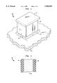
- FIG. 3 is a partial cross sectional view taken along the line 3--3 in FIG. 2;
- FIG. 4 is a perspective view of an alternate embodiment of a protective enclosure according to this invention.
- FIG. 1 illustrates a typical outdoor equipment installation within an enclosure according to a first embodiment of the present invention.
- the enclosure designated generally by the reference numeral 10
- the enclosure 10 is mounted on a platform 12, illustratively a concrete slab.
- a platform 12 illustratively a concrete slab.
- Such mounting would be by way of bolts (not shown) set into the concrete and extending through openings provided therefor in the floor of the enclosure 10.
- the enclosure 10 may be mounted at an elevated location on a pole or a building, for example.
- the illustrative enclosure 10 is formed of a top panel 14, a bottom panel 16 and side panels 18, 20, 22, 24.
- the top panel 14 includes an outer top panel wall 26, an inner top panel wall 28 which is spaced from the wall 26 and at least one connecting wall 30 joining the walls 26, 28.
- the walls 26, 28, 30 together define and surround an internal cavity.
- the top panel 14 further includes an opening 32, illustratively through the inner wall 28, communicating with the internal cavity.
- the top panel 14 is formed of a plastic material by a blow molding process. The blow molding process reduces the manufacturing cost, and the use of recycled plastic material can result in even greater cost savings.
- the bottom panel 16 and the side panels 18, 20, 22, 24 are similar in that they each include an outer wall, an inner wall spaced from the outer wall, and a connecting wall to surround and define an internal cavity, with at least one opening through one of the walls communicating with the internal cavity.
- a blow molding process is used to form the bottom panel 16 and the side panels 18, 20, 22, 24 from a plastic material.
- the enclosure 10 also includes a plurality of caps 34 each for sealing a respective one of the openings communicating with an internal cavity of a panel.
- the enclosure 10 is designed as a snap-fit assembly with the side panels 18, 20, 22, 24 extending between the top panel 14 and the bottom panel 16 to form an interior space bounded by all of the panels.
- hardware or adhesive can be utilized for joining the panels.
- the flat, hollow panels are lightweight and can be packaged for shipment in a much smaller volume than an assembled cabinet of the prior art.
- the panel 20 has an inner wall 36 and an outer wall 38 and the internal cavity of the panel 20 is filled with protective material 40.
- the material 40 can be an energy absorbing material, a masonry material, a kevlar material, a carbon fiber material, a ceramic material, an expanded metal material, or the like.
- the protective material 40 can be installed in the panels at the installation site of the enclosure 10 by pouring it through the openings of any desired ones of the panels and then sealing the openings with the caps 34. This reduces transportation costs because the panels themselves are relatively lightweight and can be transported in a stacked manner, having a smaller volume than an assembled enclosure. Further, the end user has the option of whether or not to fill any of the panel cavities with a protective material.
- FIG. 4 shows an alternate embodiment of an enclosure 50 wherein the side panel 52 is formed as a pivoting door, but the basic principles of construction of the enclosure 50 are the same as for the enclosure 10 described above. It is also known that enclosures of the type described can be made as a unitary piece with integral hinges between panels and snap-fit features along the edges of the panels so that the enclosure can be transported as a flat piece and then with proper folding an enclosure can be formed.
Abstract
Description
Claims (13)
Priority Applications (1)
| Application Number | Priority Date | Filing Date | Title |
|---|---|---|---|
| US09/075,551 US5960592A (en) | 1998-05-11 | 1998-05-11 | Protective enclosure for outdoor equipment |
Applications Claiming Priority (1)
| Application Number | Priority Date | Filing Date | Title |
|---|---|---|---|
| US09/075,551 US5960592A (en) | 1998-05-11 | 1998-05-11 | Protective enclosure for outdoor equipment |
Publications (1)
| Publication Number | Publication Date |
|---|---|
| US5960592A true US5960592A (en) | 1999-10-05 |
Family
ID=22126495
Family Applications (1)
| Application Number | Title | Priority Date | Filing Date |
|---|---|---|---|
| US09/075,551 Expired - Lifetime US5960592A (en) | 1998-05-11 | 1998-05-11 | Protective enclosure for outdoor equipment |
Country Status (1)
| Country | Link |
|---|---|
| US (1) | US5960592A (en) |
Cited By (27)
| Publication number | Priority date | Publication date | Assignee | Title |
|---|---|---|---|---|
| US6490830B2 (en) * | 2000-01-27 | 2002-12-10 | Shaogang Ruan | Life maintenance apparatus |
| US6561215B1 (en) | 2001-12-07 | 2003-05-13 | Hoad, Incorporated | Natural gas wellhead enclosure |
| EP1312873A1 (en) * | 2001-11-15 | 2003-05-21 | EISENMANN MASCHINENBAU KG (Komplementär: EISENMANN-Stiftung) | Liquidproof housing for industrial device |
| US20040000099A1 (en) * | 2002-06-26 | 2004-01-01 | Shlomit Gal | Mood regulation enclosure and methods for use thereof |
| US6749498B2 (en) | 2001-09-12 | 2004-06-15 | Arris International, Inc. | Ventilated outdoor electronics enclosure |
| US6786009B1 (en) * | 2000-08-16 | 2004-09-07 | Corporate Safe Specialists | Kit for securable enclosure |
| US6821049B1 (en) * | 2002-04-16 | 2004-11-23 | Thinking Outside, L.L.C. | Floor attachment device for storage shed |
| US20080005980A1 (en) * | 2006-07-05 | 2008-01-10 | Ding-Chen Lin | Foldable sauna cabinet |
| US20090071565A1 (en) * | 2007-09-13 | 2009-03-19 | Denis Ding | Modular production design of compressed natural gas compressor and multi-saturation liquefied natural gas dispenser systems |
| US20090223161A1 (en) * | 2008-03-06 | 2009-09-10 | Segall Stuart C | Relocatable habitat unit |
| GB2476816A (en) * | 2010-01-08 | 2011-07-13 | David Brands | Substation kiosk |
| US20130133272A1 (en) * | 2010-08-12 | 2013-05-30 | Living Quarter Technology, Inc. | Aluminum accommodations module and method of constructing same |
| FR2986027A1 (en) * | 2012-01-24 | 2013-07-26 | Bonna Sabla | RIGID HOUSING FOR TECHNICAL EQUIPMENT |
| WO2014031169A1 (en) * | 2012-08-24 | 2014-02-27 | The Uab Research Foundation | Modular shelters comprising composite panels |
| US20140109495A1 (en) * | 2008-03-06 | 2014-04-24 | Stuart Charles Segall | Relocatable habitat unit having radio frequency interactive walls |
| US20140123572A1 (en) * | 2008-03-06 | 2014-05-08 | Stuart Charles Segall | Relocatable habitat unit having interchangeable panels |
| US8943758B2 (en) * | 2012-08-16 | 2015-02-03 | Mj Outdoors, Llc | Shelter |
| US9109108B1 (en) * | 2013-08-13 | 2015-08-18 | Pak-Lite, Inc. | LVT flooring and underlayment including extruded sheet material with expanded microspheres |
| US9157249B2 (en) | 2013-03-15 | 2015-10-13 | Stuart Charles Segall | Relocatable habitat unit |
| US20190316406A1 (en) * | 2015-08-29 | 2019-10-17 | Danby Products Limited | Safe Configured For Holding Valuables |
| CN111042582A (en) * | 2019-11-20 | 2020-04-21 | 国家电网有限公司 | Equipment material isolation protection device for field maintenance of power grid |
| US20200172126A1 (en) * | 2016-11-23 | 2020-06-04 | Hyperloop Technologies, Inc. | Modular enclosed transportation structure and integrated track assembly |
| US20200370247A1 (en) * | 2019-05-24 | 2020-11-26 | Braskem S.A. | Railway sleepers and methods thereof |
| US11408165B2 (en) | 2020-06-23 | 2022-08-09 | Kurtis Kolisnek | Modular protective enclosure for outdoor equipment |
| US11473288B2 (en) | 2020-06-23 | 2022-10-18 | Kurtis Kolisnek | Modular protective enclosure for outdoor equipment |
| US11649592B2 (en) * | 2014-11-11 | 2023-05-16 | Braskem S.A. | Railroad sleeper and process for manufacturing a railroad sleeper |
| US11654943B2 (en) * | 2018-10-18 | 2023-05-23 | Westinghouse Air Brake Technologies Corporation | End of vehicle device with integrated antenna |
Citations (15)
| Publication number | Priority date | Publication date | Assignee | Title |
|---|---|---|---|---|
| US2271355A (en) * | 1941-07-16 | 1942-01-27 | Carroll V Sweet | Panel |
| US2961116A (en) * | 1956-01-03 | 1960-11-22 | Applied Radiation Corp | Thermally insulated wall structure |
| US3137744A (en) * | 1961-09-19 | 1964-06-16 | Gen Motors Corp | Refrigerating apparatus |
| US3256860A (en) * | 1964-09-22 | 1966-06-21 | Harry A Parker | Animal enclosure |
| US3305986A (en) * | 1962-08-07 | 1967-02-28 | Foam Products Corp | Insulated enclosures and panels therefor |
| US3371816A (en) * | 1965-10-22 | 1968-03-05 | Fausto M. Ricci | Collapsible receptacle |
| US3517468A (en) * | 1968-07-22 | 1970-06-30 | John Thomas Woods | Audiometric enclosure |
| US4272935A (en) * | 1980-02-19 | 1981-06-16 | Retro-Flex, Inc. | Field-installed insulation and apparatus for and method of making and installing the same |
| US4805357A (en) * | 1987-01-12 | 1989-02-21 | Aleixo Vitor C | Structural mold system |
| US5315794A (en) * | 1992-10-30 | 1994-05-31 | Professional Systems, Inc. | Enclosure for telecommunications equipment |
| US5560150A (en) * | 1995-02-15 | 1996-10-01 | Professional Systems, Inc. | Structure for telecommunications equipment enclosure |
| US5724774A (en) * | 1994-07-22 | 1998-03-10 | Rooney; James W. | Modular building assembly and method of assembling the same |
| US5749178A (en) * | 1996-08-06 | 1998-05-12 | Garmong; Victor H. | Shielded enclosure |
| US5755062A (en) * | 1996-06-20 | 1998-05-26 | Slater; Electus P. | Portable structure for housing sensitive equipment and method of fabricating same |
| US5848500A (en) * | 1997-01-07 | 1998-12-15 | Eastman Kodak Company | Light-tight enclosure and joint connectors for enclosure framework |
-
1998
- 1998-05-11 US US09/075,551 patent/US5960592A/en not_active Expired - Lifetime
Patent Citations (15)
| Publication number | Priority date | Publication date | Assignee | Title |
|---|---|---|---|---|
| US2271355A (en) * | 1941-07-16 | 1942-01-27 | Carroll V Sweet | Panel |
| US2961116A (en) * | 1956-01-03 | 1960-11-22 | Applied Radiation Corp | Thermally insulated wall structure |
| US3137744A (en) * | 1961-09-19 | 1964-06-16 | Gen Motors Corp | Refrigerating apparatus |
| US3305986A (en) * | 1962-08-07 | 1967-02-28 | Foam Products Corp | Insulated enclosures and panels therefor |
| US3256860A (en) * | 1964-09-22 | 1966-06-21 | Harry A Parker | Animal enclosure |
| US3371816A (en) * | 1965-10-22 | 1968-03-05 | Fausto M. Ricci | Collapsible receptacle |
| US3517468A (en) * | 1968-07-22 | 1970-06-30 | John Thomas Woods | Audiometric enclosure |
| US4272935A (en) * | 1980-02-19 | 1981-06-16 | Retro-Flex, Inc. | Field-installed insulation and apparatus for and method of making and installing the same |
| US4805357A (en) * | 1987-01-12 | 1989-02-21 | Aleixo Vitor C | Structural mold system |
| US5315794A (en) * | 1992-10-30 | 1994-05-31 | Professional Systems, Inc. | Enclosure for telecommunications equipment |
| US5724774A (en) * | 1994-07-22 | 1998-03-10 | Rooney; James W. | Modular building assembly and method of assembling the same |
| US5560150A (en) * | 1995-02-15 | 1996-10-01 | Professional Systems, Inc. | Structure for telecommunications equipment enclosure |
| US5755062A (en) * | 1996-06-20 | 1998-05-26 | Slater; Electus P. | Portable structure for housing sensitive equipment and method of fabricating same |
| US5749178A (en) * | 1996-08-06 | 1998-05-12 | Garmong; Victor H. | Shielded enclosure |
| US5848500A (en) * | 1997-01-07 | 1998-12-15 | Eastman Kodak Company | Light-tight enclosure and joint connectors for enclosure framework |
Cited By (38)
| Publication number | Priority date | Publication date | Assignee | Title |
|---|---|---|---|---|
| US6490830B2 (en) * | 2000-01-27 | 2002-12-10 | Shaogang Ruan | Life maintenance apparatus |
| US6786009B1 (en) * | 2000-08-16 | 2004-09-07 | Corporate Safe Specialists | Kit for securable enclosure |
| US6749498B2 (en) | 2001-09-12 | 2004-06-15 | Arris International, Inc. | Ventilated outdoor electronics enclosure |
| EP1312873A1 (en) * | 2001-11-15 | 2003-05-21 | EISENMANN MASCHINENBAU KG (Komplementär: EISENMANN-Stiftung) | Liquidproof housing for industrial device |
| US6561215B1 (en) | 2001-12-07 | 2003-05-13 | Hoad, Incorporated | Natural gas wellhead enclosure |
| US6821049B1 (en) * | 2002-04-16 | 2004-11-23 | Thinking Outside, L.L.C. | Floor attachment device for storage shed |
| US20040000099A1 (en) * | 2002-06-26 | 2004-01-01 | Shlomit Gal | Mood regulation enclosure and methods for use thereof |
| US20080005980A1 (en) * | 2006-07-05 | 2008-01-10 | Ding-Chen Lin | Foldable sauna cabinet |
| US20090071565A1 (en) * | 2007-09-13 | 2009-03-19 | Denis Ding | Modular production design of compressed natural gas compressor and multi-saturation liquefied natural gas dispenser systems |
| US20140202114A1 (en) * | 2008-03-06 | 2014-07-24 | Stuart C. Segall | Relocatable Habitat Unit and Method of Assembly |
| US20150354199A1 (en) * | 2008-03-06 | 2015-12-10 | Stuart Charles Segall | Relocatable Habitat Unit |
| US10036157B2 (en) | 2008-03-06 | 2018-07-31 | Stuart Charles Segall | Relocatable habitat unit |
| US9920513B2 (en) * | 2008-03-06 | 2018-03-20 | Stuart Charles Segall | Relocatable habitat unit |
| US9109356B2 (en) * | 2008-03-06 | 2015-08-18 | Stuart C. Segall | Relocatable habitat unit and method of assembly |
| US9016002B2 (en) * | 2008-03-06 | 2015-04-28 | Stuart Charles Segall | Relocatable habitat unit having interchangeable panels |
| US8677698B2 (en) * | 2008-03-06 | 2014-03-25 | Stuart C. Segall | Relocatable habitat unit |
| US20140109495A1 (en) * | 2008-03-06 | 2014-04-24 | Stuart Charles Segall | Relocatable habitat unit having radio frequency interactive walls |
| US20140123572A1 (en) * | 2008-03-06 | 2014-05-08 | Stuart Charles Segall | Relocatable habitat unit having interchangeable panels |
| US20090223161A1 (en) * | 2008-03-06 | 2009-09-10 | Segall Stuart C | Relocatable habitat unit |
| GB2476816A (en) * | 2010-01-08 | 2011-07-13 | David Brands | Substation kiosk |
| US20130133272A1 (en) * | 2010-08-12 | 2013-05-30 | Living Quarter Technology, Inc. | Aluminum accommodations module and method of constructing same |
| EP2620564A1 (en) * | 2012-01-24 | 2013-07-31 | Bonna Sabla | Rigid shelter for technical equipment |
| FR2986027A1 (en) * | 2012-01-24 | 2013-07-26 | Bonna Sabla | RIGID HOUSING FOR TECHNICAL EQUIPMENT |
| US8943758B2 (en) * | 2012-08-16 | 2015-02-03 | Mj Outdoors, Llc | Shelter |
| WO2014031169A1 (en) * | 2012-08-24 | 2014-02-27 | The Uab Research Foundation | Modular shelters comprising composite panels |
| US10352059B2 (en) | 2012-08-24 | 2019-07-16 | The Uab Research Foundation | Modular shelters comprising composite panels |
| US9157249B2 (en) | 2013-03-15 | 2015-10-13 | Stuart Charles Segall | Relocatable habitat unit |
| US9988806B2 (en) | 2013-03-15 | 2018-06-05 | Stuart Charles Segall | Relocatable habitat unit |
| US9109108B1 (en) * | 2013-08-13 | 2015-08-18 | Pak-Lite, Inc. | LVT flooring and underlayment including extruded sheet material with expanded microspheres |
| US11649592B2 (en) * | 2014-11-11 | 2023-05-16 | Braskem S.A. | Railroad sleeper and process for manufacturing a railroad sleeper |
| US20190316406A1 (en) * | 2015-08-29 | 2019-10-17 | Danby Products Limited | Safe Configured For Holding Valuables |
| US10781625B2 (en) * | 2015-08-29 | 2020-09-22 | Intirion Corporation | Safe configured for holding valuables |
| US20200172126A1 (en) * | 2016-11-23 | 2020-06-04 | Hyperloop Technologies, Inc. | Modular enclosed transportation structure and integrated track assembly |
| US11654943B2 (en) * | 2018-10-18 | 2023-05-23 | Westinghouse Air Brake Technologies Corporation | End of vehicle device with integrated antenna |
| US20200370247A1 (en) * | 2019-05-24 | 2020-11-26 | Braskem S.A. | Railway sleepers and methods thereof |
| CN111042582A (en) * | 2019-11-20 | 2020-04-21 | 国家电网有限公司 | Equipment material isolation protection device for field maintenance of power grid |
| US11408165B2 (en) | 2020-06-23 | 2022-08-09 | Kurtis Kolisnek | Modular protective enclosure for outdoor equipment |
| US11473288B2 (en) | 2020-06-23 | 2022-10-18 | Kurtis Kolisnek | Modular protective enclosure for outdoor equipment |
Similar Documents
| Publication | Publication Date | Title |
|---|---|---|
| US5960592A (en) | Protective enclosure for outdoor equipment | |
| EP2474213B1 (en) | Telecommunications enclosures | |
| US4677798A (en) | Steel shell modules for prisoner detention facilities | |
| CA2071303C (en) | Utility power pole system | |
| US5560150A (en) | Structure for telecommunications equipment enclosure | |
| US8689932B2 (en) | On-base enclosure | |
| KR101486023B1 (en) | Explosion-proof panel, explosion-proof panel connection assembly and explosion-proof modular structure including the same | |
| US11665874B2 (en) | Mission configurable shelter | |
| US20170030571A1 (en) | Lamppost with inner compartment fitted into the lamppost base for telecommunications systems | |
| KR101441255B1 (en) | Explosion-proof panel, explosion-proof panel connection assembly and explosion-proof modular structure including the same | |
| US20150211245A1 (en) | Free-standing form for building a pre-insulated wall and method of building a structure therewith | |
| KR102115829B1 (en) | Structure for Anti-Sweating of Fire Door | |
| US6332659B1 (en) | Modular cabinet for housing electronics | |
| EP1890367B1 (en) | To-be introduced improvements for cabinets housing telecommunication equipment | |
| EP2631405A1 (en) | Composite window support | |
| KR101023524B1 (en) | Soundproof wall with enhanced structure | |
| EP2052119B1 (en) | Shelter, method for providing a wall or a panel with a bullet-proof and/or splinter-proof layer, and shelter, vehicle, vessel or aircraft provided with a wall or a panel manufactured according to this method | |
| WO2002056411A2 (en) | Installations for wireless communication | |
| CN211860794U (en) | Box data center and thermal-insulated box thereof | |
| KR200368017Y1 (en) | An Entrance Door | |
| KR200270185Y1 (en) | A panel having fireproof material | |
| EP1250508B1 (en) | Frame structure | |
| JP6934845B2 (en) | Dry fence | |
| GB2304467A (en) | Electrical apparatus enclosure | |
| JPH043995Y2 (en) |
Legal Events
| Date | Code | Title | Description |
|---|---|---|---|
| AS | Assignment |
Owner name: LUCENT TECHNOLOGIES INC., NEW JERSEY Free format text: ASSIGNMENT OF ASSIGNORS INTEREST;ASSIGNORS:LILIENTHAL, PETER F., II;PAWLENKO, IVAN;REEL/FRAME:009216/0783 Effective date: 19980507 |
|
| FEPP | Fee payment procedure |
Free format text: PAYOR NUMBER ASSIGNED (ORIGINAL EVENT CODE: ASPN); ENTITY STATUS OF PATENT OWNER: LARGE ENTITY |
|
| STCF | Information on status: patent grant |
Free format text: PATENTED CASE |
|
| AS | Assignment |
Owner name: THE CHASE MANHATTAN BANK, AS COLLATERAL AGENT, TEX Free format text: CONDITIONAL ASSIGNMENT OF AND SECURITY INTEREST IN PATENT RIGHTS;ASSIGNOR:LUCENT TECHNOLOGIES INC. (DE CORPORATION);REEL/FRAME:011722/0048 Effective date: 20010222 |
|
| FPAY | Fee payment |
Year of fee payment: 4 |
|
| AS | Assignment |
Owner name: LUCENT TECHNOLOGIES INC., NEW JERSEY Free format text: TERMINATION AND RELEASE OF SECURITY INTEREST IN PATENT RIGHTS;ASSIGNOR:JPMORGAN CHASE BANK, N.A. (FORMERLY KNOWN AS THE CHASE MANHATTAN BANK), AS ADMINISTRATIVE AGENT;REEL/FRAME:018590/0047 Effective date: 20061130 |
|
| FPAY | Fee payment |
Year of fee payment: 8 |
|
| FPAY | Fee payment |
Year of fee payment: 12 |
|
| AS | Assignment |
Owner name: OMEGA CREDIT OPPORTUNITIES MASTER FUND, LP, NEW YORK Free format text: SECURITY INTEREST;ASSIGNOR:WSOU INVESTMENTS, LLC;REEL/FRAME:043966/0574 Effective date: 20170822 Owner name: OMEGA CREDIT OPPORTUNITIES MASTER FUND, LP, NEW YO Free format text: SECURITY INTEREST;ASSIGNOR:WSOU INVESTMENTS, LLC;REEL/FRAME:043966/0574 Effective date: 20170822 |
|
| AS | Assignment |
Owner name: WSOU INVESTMENTS, LLC, CALIFORNIA Free format text: ASSIGNMENT OF ASSIGNORS INTEREST;ASSIGNOR:ALCATEL LUCENT;REEL/FRAME:044000/0053 Effective date: 20170722 |
|
| AS | Assignment |
Owner name: WSOU INVESTMENTS, LLC, CALIFORNIA Free format text: RELEASE BY SECURED PARTY;ASSIGNOR:OCO OPPORTUNITIES MASTER FUND, L.P. (F/K/A OMEGA CREDIT OPPORTUNITIES MASTER FUND LP;REEL/FRAME:049246/0405 Effective date: 20190516 |
|
| AS | Assignment |
Owner name: OT WSOU TERRIER HOLDINGS, LLC, CALIFORNIA Free format text: SECURITY INTEREST;ASSIGNOR:WSOU INVESTMENTS, LLC;REEL/FRAME:056990/0081 Effective date: 20210528 |