US5979409A - Integral returnless pressure regulator for a fuel injection system - Google Patents
Integral returnless pressure regulator for a fuel injection system Download PDFInfo
- Publication number
- US5979409A US5979409A US09/158,636 US15863698A US5979409A US 5979409 A US5979409 A US 5979409A US 15863698 A US15863698 A US 15863698A US 5979409 A US5979409 A US 5979409A
- Authority
- US
- United States
- Prior art keywords
- fuel
- valve
- chamber
- valve member
- pressure
- Prior art date
- Legal status (The legal status is an assumption and is not a legal conclusion. Google has not performed a legal analysis and makes no representation as to the accuracy of the status listed.)
- Expired - Lifetime
Links
- 239000000446 fuel Substances 0.000 title claims abstract description 330
- 238000002347 injection Methods 0.000 title 1
- 239000007924 injection Substances 0.000 title 1
- 230000001105 regulatory effect Effects 0.000 claims abstract description 23
- 230000004044 response Effects 0.000 claims abstract description 22
- 230000033228 biological regulation Effects 0.000 claims abstract description 21
- 230000003247 decreasing effect Effects 0.000 claims abstract description 10
- 238000004891 communication Methods 0.000 claims abstract description 9
- 238000007789 sealing Methods 0.000 abstract description 5
- 210000002445 nipple Anatomy 0.000 description 6
- 239000002828 fuel tank Substances 0.000 description 5
- 230000007423 decrease Effects 0.000 description 3
- 238000004519 manufacturing process Methods 0.000 description 3
- 238000002485 combustion reaction Methods 0.000 description 2
- 238000007667 floating Methods 0.000 description 2
- 230000006872 improvement Effects 0.000 description 2
- 230000014759 maintenance of location Effects 0.000 description 2
- 241000169624 Casearia sylvestris Species 0.000 description 1
- 230000009471 action Effects 0.000 description 1
- 230000008859 change Effects 0.000 description 1
- 238000011109 contamination Methods 0.000 description 1
- 238000006073 displacement reaction Methods 0.000 description 1
- 238000001914 filtration Methods 0.000 description 1
- 238000003754 machining Methods 0.000 description 1
- 238000012423 maintenance Methods 0.000 description 1
- 239000002184 metal Substances 0.000 description 1
- 238000012986 modification Methods 0.000 description 1
- 230000004048 modification Effects 0.000 description 1
- 238000005086 pumping Methods 0.000 description 1
- 230000009467 reduction Effects 0.000 description 1
Images


Classifications
-
- F—MECHANICAL ENGINEERING; LIGHTING; HEATING; WEAPONS; BLASTING
- F02—COMBUSTION ENGINES; HOT-GAS OR COMBUSTION-PRODUCT ENGINE PLANTS
- F02M—SUPPLYING COMBUSTION ENGINES IN GENERAL WITH COMBUSTIBLE MIXTURES OR CONSTITUENTS THEREOF
- F02M69/00—Low-pressure fuel-injection apparatus ; Apparatus with both continuous and intermittent injection; Apparatus injecting different types of fuel
- F02M69/46—Details, component parts or accessories not provided for in, or of interest apart from, the apparatus covered by groups F02M69/02 - F02M69/44
- F02M69/54—Arrangement of fuel pressure regulators
-
- Y—GENERAL TAGGING OF NEW TECHNOLOGICAL DEVELOPMENTS; GENERAL TAGGING OF CROSS-SECTIONAL TECHNOLOGIES SPANNING OVER SEVERAL SECTIONS OF THE IPC; TECHNICAL SUBJECTS COVERED BY FORMER USPC CROSS-REFERENCE ART COLLECTIONS [XRACs] AND DIGESTS
- Y10—TECHNICAL SUBJECTS COVERED BY FORMER USPC
- Y10T—TECHNICAL SUBJECTS COVERED BY FORMER US CLASSIFICATION
- Y10T137/00—Fluid handling
- Y10T137/7722—Line condition change responsive valves
- Y10T137/7781—With separate connected fluid reactor surface
- Y10T137/7835—Valve seating in direction of flow
- Y10T137/7836—Flexible diaphragm or bellows reactor
Definitions
- the present invention relates generally to a fuel system for an internal combustion engine, for example, for an automotive vehicle, and particularly relates to a fuel pressure regulator for disposition adjacent a fuel rail for regulating the pressure within the fuel rail without a separate return conduit for returning excess fuel to the fuel tank.
- a fuel pump supplies a flow of fuel to a pressure regulator adjacent a fuel rail at a constant flow rate for all fuel demand modes, i.e., at all engine or vehicle speeds.
- the system fuel pressure provided by the fuel pump is maintained at a slightly higher pressure than the pressure in the fuel rail.
- the function of the returnless regulator is to reduce the pressure supplied by the fuel pump to the predetermined regulation pressure which enables the fuel pressure in the fuel rail and the fuel injectors to deliver the correct amount of fuel to the engine.
- the lower fuel rail pressure is determined by the returnless regulator, while the slightly higher system pressure is determined by a pressure relief valve carried within a fuel pump module located with a fuel tank.
- a pressure relief valve carried within a fuel pump module located with a fuel tank.
- the pressure relief valve enables the excess fuel to be returned to the fuel pump module without a fuel return line from the returnless regulator to the fuel pump module or fuel tank.
- the returnless regulator can be optionally vacuumed referenced to the intake manifold so that a constant differential pressure across the fuel injectors can be maintained.
- a regulator assembly having a housing carrying a movable diaphragm defining part of a fuel pressure regulating chamber, the diaphragm being biased by a spring disposed on an opposite side of the diaphragm from the chamber.
- the housing has a fuel inlet port leading to the chamber which lies in communication with the fuel pump which supplies fuel under pressure to the regulator.
- the housing also includes a fuel outlet port for delivering pressure regulated fuel to the injector fuel rail and injectors and which outlet port is exposed to, i.e., in communication with the chamber in the housing.
- a normally open valve is provided in the housing for normally flowing fuel from the fuel inlet port to the fuel outlet port during operation of the vehicle.
- the normally open valve includes a valve body having a valve member movable in the valve body, e.g., a ball, a valve seat at one end of the valve body defining an opening and a spring engaging the valve member and biasing the member for movement toward the seat, i.e., toward a valve-closed position.
- the diaphragm carries an element, e.g., a projection, which is engageable with the valve member.
- the projection displaces the valve member away from the seat to enable increased flow of fuel from the fuel pump through the valve into the chamber in response to a fuel pressure in the chamber below a predetermined fuel regulation pressure and permits displacement of the valve member toward the seat to enable decreased flow of fuel from the fuel pump through the valve into the chamber in response to a fuel pressure in the chamber above the predetermined fuel regulation pressure.
- the valve member i.e., the ball
- the valve body i.e., the ball
- the diaphragm carries a flange which has a pair of side-by-side circular recesses lying in communication with the valve seat opening enabling flow of fuel through the valve seat opening into the recesses and into the chamber.
- the recesses are readily formed in the flange of the diaphragm by a machine operation and provide enhanced porting action.
- a fuel filter is formed integrally on the fuel inlet side of the valve body.
- a pair of retainers are employed to capture the additional sealing rings.
- an upper retainer ring is provided about a stepped portion of a lower housing part of the regulator housing.
- the lower housing part mounts the valve body and includes an annular surface having a plurality of openings about the valve body for flowing fuel from the chamber to the fuel rail.
- the upper O-ring retainer ring has a plurality of recesses and upstanding spring-biased bosses.
- the bosses are received in certain openings of the stepped housing part while the recesses of the retainer ring lie in registration with remaining openings of the stepped housing part to enable fuel flow from the valve body into the chamber and through the registering openings and recesses to the fuel rail.
- a lower retainer ring also captures a lower O-ring seal about the lower housing part and simultaneously provides a mounting for the filter, i.e., a screen for filtering fuel flowing into the valve body.
- a fuel pressure regulator assembly comprising a housing having a movable diaphragm defining a portion of a fuel pressure regulating chamber, the housing having a fuel inlet port for receiving fuel under pressure from a fuel pump and a fuel outlet port for delivering pressure regulated fuel to fuel injectors, a normally open valve having opposite sides exposed to pressurized fuel from the fuel pump and fuel in the chamber, respectively, for flowing fuel from the fuel pump into and through the chamber, the valve comprising a valve body having a passage, a valve member movable in the passage, a valve seat adjacent one end of the valve member and defining an opening therethrough and a spring engaging the valve member and biasing the valve member for movement toward the seat, the valve member being spaced from walls of the valve body and being unguided within the valve body and a part carried by the diaphragm and engageable with the valve member to move the valve member away from the seat and enable increased flow of fuel from the fuel pump through the valve into the chamber
- a fuel pressure regulator assembly comprising a housing having a movable diaphragm defining a portion of a fuel pressure regulating chamber, the housing comprising a fuel inlet port for receiving fuel under pressure from a fuel pump and a fuel outlet port for delivering pressure regulated fuel to a fuel rail, a normally open valve having opposite sides exposed to pressurized fuel from the fuel pump and fuel in the chamber, respectively, for flowing fuel from the fuel pump into and through the chamber, the valve comprising a valve body having a passage, a valve member movable in the passage, a valve seat adjacent one end of the valve member and defining an opening therethrough and a spring engaging the valve member and biasing the valve member for movement toward the seat, the diaphragm including a central flange having a depending projection for engaging the valve element, the flange having a pair of off-center recesses formed on a side thereof in partial registration with the opening in one end of the valve body and in communication with the chamber
- a fuel pressure regulator assembly comprising a housing having a movable diaphragm defining a portion of a fuel pressure regulating chamber, the housing having a fuel inlet port for receiving fuel under pressure from a fuel pump and a fuel outlet port for delivering pressure regulated fuel to fuel injectors, a normally open valve having opposite sides exposed to pressurized fuel from the fuel pump and fuel in the chamber, respectively, for flowing fuel from the fuel pump into and through the chamber, the valve comprising a valve body having a passage, a valve member movable in the passage, a valve seat adjacent one end of the valve member and defining an opening therethrough and a spring engaging the valve member and biasing the valve member for movement toward the seat and a part carried by the diaphragm and engageable with the valve member to move the valve member away from the seat and enable increased flow of fuel from the fuel pump through the valve into the chamber in response to a fuel pressure in the chamber below a predetermined fuel regulation pressure and
- FIG. 1 is a schematic representation of a returnless fuel regulator system according to the present invention
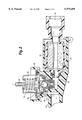
- FIG. 2 is a fragmentary cross-sectional view of the end of a fuel rail with a returnless regulator disposed in a socket thereof, all constructed in accordance with the present invention
- FIG. 3 is an enlarged cross-sectional view of the pressure regulator contained within the fuel rail end
- FIG. 4 is a reduced top plan view of an upper retainer ring used in the regulator illustrated in FIG. 3;
- FIG. 5 is a cross-sectional view of the underside of the flange of the diaphragm of the regulator of FIG. 3;
- FIG. 6 is a plan view of an upper portion of a second retainer ring used in the regulator illustrated in FIG. 3;
- FIG. 7 is a bottom plan view of the regulator illustrating the fuel filter and the upper retainer ring.
- FIG. 1 there is illustrated a returnless regulator fuel system which includes a fuel tank 10, a fuel pump module 12 for pumping fuel at a constant flow rate, a fuel line 14 within the fuel pump module containing a check valve 16, a main supply fuel line 18 for supplying fuel from the pump module 12 and tank 10 to a fuel rail 20 and, hence, to injectors 22, in communication with the fuel rail, a primary fuel filter 24 in line 18 and an integral returnless regulator 26 constructed in accordance with the present invention carried by an end socket 31 of the fuel rail 20.
- fuel pump module 12 pumps fuel at a constant flow rate at a system pressure in line 18 higher than a predetermined regulated pressure of the fuel in fuel rail 20 and injectors 22, the reduction in pressure being accomplished by the returnless regulator 26. Excess fuel is returned to the fuel pump module by way of a pressure relief valve 28 and connecting line 30 within the fuel pump module.
- socket 31 is coaxial with the fuel rail 20.
- Socket 31 opens at one end to line 18 and reduces down at its opposite end to a reduced axial passage 32 for flowing fuel from line 18 to the regulator 26.
- a main fuel filter cartridge 34 is disposed in the enlarged diameter portion of socket 31 for flowing fuel under pressure from line 18 through the annular cartridge 34 and into passage 32 for flow to the regulator 26.
- Regulator 26 comprises a generally cylindrical housing having an upper, generally inverted cup-shaped housing part 38 and a stepped lower housing part 40 joined and sealed to one another with confronting margins 42 and 44, respectively.
- the margins 42 and 44 also clamp between them the outer margin of a diaphragm 46 mounting a central flange or part 48.
- Part 48 includes a lower annular rim 50 underlying an inner margin of diaphragm 46.
- An upper, generally cup-shaped flange 52 is secured to an upper end portion of part 48 and receives the lower end of a helical coil spring 54.
- the upper end of spring 54 bears against the upper end of upper housing part 38 and surrounds a nipple 56.
- nipple 56 is open to the atmosphere. Consequently, spring 54 resides in an upper chamber 58, while the diaphragm 46 defines in part a lower chamber 60.
- part 48 includes a central, generally axially extending projection 62 which extends downwardly into an opening 64 forming part of a normally open valve assembly, generally designated 66, and described hereinafter.
- the underside of part 48 includes a pair of cylindrical recesses 68 having centers lying on a common diameter and spaced from the axis of part 48.
- the recesses 68 as illustrated in FIG. 3, in part overlie the opening 64 of the valve assembly 66 and in part open into chamber 60.
- the recesses 68 are preferably formed by machining the underside of the metal part 48 and form ports for flowing fuel from valve 66 into chamber 60.
- the valve assembly 66 includes a cylindrical valve body 70 which comprises the valve opening 64 at an upper end thereof surrounded by valve seat 65 and an enlarged cylindrical passage 72 in which a valve element 74, for example, a ball, is disposed.
- a valve element 74 for example, a ball
- ball 74 is free-floating in passage 72, i.e., it is spaced a substantial distance from the side walls of the valve body 70.
- Valve element 74 rests on an underlying coil spring 76.
- the lower end of the coil spring 76 bears on an in-turned flange 78 forming the lower terminus of the lower housing part 40.
- the coil spring 76 biases the ball upwardly and it will be appreciated that it engages the tip of the downward projection 62 of part 48, as illustrated.
- the lower terminus of lower housing part 40 includes an opening 77 defining a fuel inlet port for the regulator.
- the ball 74 has a diameter well short of the diameter of the cylindrical passage 72 to provide increased response time to changes in pressure and virtually unobstructed flow past the ball to the valve opening.
- the ball diameter is 7.144 mm and the diameter of the passage 72 is 8.05 mm, providing a flow area of 10.806 mm 2 past the ball.
- this area should be between 15-25% of the area of the passage 72.
- the lower housing part 40 includes a number of reduced diameter steps toward its lower in-turned flange 78.
- the step 80 forms a seat for the lower end of the valve body 70.
- annular surface 82 extending about valve body 70 and forming the next step above step 80, there is provided a plurality of circumferentially spaced openings 84.
- a retainer ring 86 is disposed externally about the lower housing part 40 below annular surface 82 and includes a plurality of upstanding bosses 88.
- Each boss 88 includes opposed, generally semi-circular resilient parts 89, each having rims 90, such that the parts 89 of bosses 88 can be received in a predetermined number of the openings 84.
- the retainer ring also includes recesses 90 (FIGS. 3, 4 and 7) underlying the surface 82 and particularly underlying adjacent remaining pairs of openings 84 which are not occupied by bosses 88. That is, each recess 90 registers with two openings 84 of the lower housing part whereby fuel can flow from chamber 60 through openings 84 and recesses 90 into the fuel rail.
- the retainer ring 86 has an outwardly directed flange 92. Flange 92 forms a retaining flange for an O-ring seal 94 for sealing the regulator within the socket 30 on the end of the fuel rail.
- a lower retainer ring comprised of an annular, generally cup-shaped member 100, having a central upstanding nipple 102 received within the opening 104 of the lower housing part 40.
- the nipple includes a radially enlarged edge for a snap-fit past the margins of opening 104 for retention on the lower housing part.
- the lower retainer ring 100 includes an upstanding outer wall 106 having a plurality of ledges 108 spaced thereabout for retaining a generally cup-shaped filter element 110 on the retainer ring 100.
- the filter element 110 comprises an annular member having a screen 112 through which fuel is filtered upon passing through the screen and into the lower housing part 40.
- the filter element 110 includes an inwardly directed flange for engaging over ledge 108 whereby the filter is secured to the regulator.
- the lower retainer ring 100 serves not only to secure the fuel filter 112 to the regulator but also to retain an additional O-ring seal 114 on the last reduced diameter portion of the stepped lower housing part 40.
- the function of the regulator is to reduce the supplied fuel pressure to a predetermined regulator pressure such that a constant flow rate of fuel at constant regulated pressure is supplied to the fuel rail and fuel injectors.
- the regulator has three different operating modes. In a first operating mode, in which the engine is running and variable loads are being imposed on the engine, the regulator valve is movable to increase or decrease the fuel flow through the valve to the fuel rail. That is, as the engine consumes more fuel, the valve opens further to increase the flow rate of fuel to the fuel rail and, as the engine uses less fuel, the valve decreases the flow rate of fuel to the fuel rail and injectors.
- the pressure acting on the chamber 60 will decrease and the spring 54 causes the diaphragm 46 to move toward the valve assembly 66.
- Projection 62 thus moves downwardly as illustrated in FIG. 3 to displace the valve member 74 further from the valve seat 65 about the valve opening 64 and against the bias of spring 76 to increase the flow of fuel through the valve into the fuel rail.
- the fuel flows under pressure through the inlet port 77 past nipple 102 into the valve body 70, about ball 90, past seat 65 and through valve opening 64.
- the fuel Upon passing opening 64, the fuel enters the recesses 68 of the diaphragm part 48 and reverses direction for flow into chamber 60 and through the openings 84 which register with the recesses 90 of the upper retaining ring 86 for flow into the fuel rail.
- the fuel pressure increases in chamber 60, displacing the diaphragm 46 away from the valve 66 and against the bias of spring 54. This, in turn, enables spring 76 to move valve element 74 closer to the valve seat 65, hence reducing the flow of fuel through the valve and maintaining the fuel at the regulated pressure.
- the fuel pressure in chamber 60 increases and the valve closes. The valve will stay closed until the injectors fire again.
- the valve sealing surface or seat 65 is coined.
- a second mode of operation occurs when the vehicle is shut off.
- the valve 66 remains open and the fuel rail pressure and the system pressure equalize.
- the pressure relief valve 28 has a closing time associated with it and seals when the pressure is equalized so that the vehicle will have fuel under pressure during a restart.
- the check valve 16 is located in the fuel pump and this check valve also seals the system, maintaining the system pressure.
- a hot soak mode the engine may run hot or run during hot ambient conditions.
- heat builds up in the fuel rail and hence the pressure increases.
- the regulator 26 is normally open, the valve will eventually close under these conditions. That is, as the fuel rail pressure rises, the diaphragm 46 is displaced upwardly, enabling the valve element 74 to seal against seat 65. Once sealed, the pressure continues to rise.
- the pressure per unit area on the valve element 74 will overcome the force of spring 76 and the system pressure to crack open the valve and relieve the pressure.
- the regulator of the present invention can also be referenced to the intake manifold as illustrated in FIG. 1. That is, the nipple 56 can be connected via a line 130 to the fuel manifold 132. This ensures a constant differential pressure across the fuel injectors, notwithstanding variations in the pressure and the manifold during variable driving conditions. Hence, the change in force on the diaphragm in the control chamber 58 enables the maintenance of a constant pressure difference across the injectors under variable driving conditions.
Abstract
Description
Claims (13)
Priority Applications (1)
| Application Number | Priority Date | Filing Date | Title |
|---|---|---|---|
| US09/158,636 US5979409A (en) | 1998-09-22 | 1998-09-22 | Integral returnless pressure regulator for a fuel injection system |
Applications Claiming Priority (1)
| Application Number | Priority Date | Filing Date | Title |
|---|---|---|---|
| US09/158,636 US5979409A (en) | 1998-09-22 | 1998-09-22 | Integral returnless pressure regulator for a fuel injection system |
Publications (1)
| Publication Number | Publication Date |
|---|---|
| US5979409A true US5979409A (en) | 1999-11-09 |
Family
ID=22569027
Family Applications (1)
| Application Number | Title | Priority Date | Filing Date |
|---|---|---|---|
| US09/158,636 Expired - Lifetime US5979409A (en) | 1998-09-22 | 1998-09-22 | Integral returnless pressure regulator for a fuel injection system |
Country Status (1)
| Country | Link |
|---|---|
| US (1) | US5979409A (en) |
Cited By (16)
| Publication number | Priority date | Publication date | Assignee | Title |
|---|---|---|---|---|
| WO2001063373A1 (en) * | 2000-02-22 | 2001-08-30 | Robert Bosch Gmbh | Device with a membrane arrangement |
| US6325048B1 (en) * | 1999-07-07 | 2001-12-04 | Siemens Automotive Corporation | Integrated mounting of a pressure regulator in an automotive fuel system |
| WO2002025148A1 (en) * | 2000-09-21 | 2002-03-28 | Siemens Aktiengesellschaft | Pressure-limiting valve |
| US20030190239A1 (en) * | 2002-04-08 | 2003-10-09 | Bruce Stephens | Electric fuel pump with universal relief valve installed in the pump inlet |
| US20030226592A1 (en) * | 2002-06-06 | 2003-12-11 | Siemens Vdo Automotive Corporation | Pressure regulator including a press-fit spring retainer |
| US20040007267A1 (en) * | 2002-06-06 | 2004-01-15 | Siemens Vdo Automotive Corporation | Flow-through pressure regulator including a perforated diaphragm-to-seat spring retainer |
| US20040055645A1 (en) * | 2002-09-25 | 2004-03-25 | Siemens Vdo Automotive Corporation | Flow-through pressure regulator including a housing with a press-fit closure member assembly |
| US20040055644A1 (en) * | 2002-09-25 | 2004-03-25 | Siemens Vdo Automotive Corporation | Flow-through pressure regulator including a closure member assembly integrated with a housing |
| US20040226541A1 (en) * | 2002-06-21 | 2004-11-18 | Crary Lynwood F. | No-return loop fuel system |
| US20040244839A1 (en) * | 2003-06-06 | 2004-12-09 | Siemens Vdo Automotive Corporation | Pressure regulator including a fixed valve ball and method of assembling the same |
| US20090139915A1 (en) * | 2000-07-25 | 2009-06-04 | Davco Technology, Llc | Fluid Filter with Pressure Relief Valve and Bypass Valve |
| US20090188566A1 (en) * | 2008-01-28 | 2009-07-30 | Abb Ag | Pneumatic pressure regulator |
| US20100037965A1 (en) * | 2008-08-14 | 2010-02-18 | Caterpillar Inc. | Check valve with separate spherical spring guide |
| US20120018658A1 (en) * | 2010-07-21 | 2012-01-26 | Taprite-Fassco Manufacturing, Inc. D/B/A Taprite | Pressure reducing valve |
| US20130340861A1 (en) * | 2012-06-20 | 2013-12-26 | Caterpillar Inc | Check valve of fuel system |
| US20140295310A1 (en) * | 2011-12-16 | 2014-10-02 | Murata Manufacturing Co., Ltd. | Valve and fuel cell system |
Citations (17)
| Publication number | Priority date | Publication date | Assignee | Title |
|---|---|---|---|---|
| US4646700A (en) * | 1985-04-17 | 1987-03-03 | Walbro Corporation | Pressure regulator for liquid fuel system |
| US4660597A (en) * | 1985-06-26 | 1987-04-28 | Colt Industries Operating Corp | Fuel pressure regulator |
| US4742845A (en) * | 1987-09-11 | 1988-05-10 | Weber U.S.A., Inc. | Fuel pressure regulator valve |
| US4756289A (en) * | 1986-02-12 | 1988-07-12 | General Motors Corporation | Self-contained fuel pressure regulator |
| US4774923A (en) * | 1986-11-07 | 1988-10-04 | Aisan Kogyo Kabushiki Kaisha | Pressure regulating valve |
| US5195494A (en) * | 1992-02-27 | 1993-03-23 | Walbro Corporation | Fuel delivery system with outlet pressure regulation |
| US5220941A (en) * | 1992-06-02 | 1993-06-22 | Walbro Corporation | Fuel pressure regulator |
| US5265644A (en) * | 1992-06-02 | 1993-11-30 | Walbro Corporation | Fuel pressure regulator |
| US5279327A (en) * | 1992-08-31 | 1994-01-18 | Orbital Walbro Corporation | Pressure regulator |
| US5398655A (en) * | 1994-01-14 | 1995-03-21 | Walbro Corporation | Manifold referenced returnless fuel system |
| US5413077A (en) * | 1994-05-09 | 1995-05-09 | Siemens Automotive L.P. | Non-return fuel system with fuel pressure vacuum response |
| US5458104A (en) * | 1994-01-14 | 1995-10-17 | Walbro Corporation | Demand fuel pressure regulator |
| US5509390A (en) * | 1994-01-14 | 1996-04-23 | Walbro Corporation | Temperature-responsive demand fuel pressure regulator |
| US5533478A (en) * | 1994-04-13 | 1996-07-09 | Siemens Automotive L.P. | Discrete filter and pressure regulator mounting for a fuel rail |
| US5579739A (en) * | 1994-01-14 | 1996-12-03 | Walbro Corporation | Returnless fuel system with demand fuel pressure regulator |
| US5609138A (en) * | 1995-06-17 | 1997-03-11 | Robert Bosch Gmbh | Pressure regulating device for a fuel delivery system |
| US5619972A (en) * | 1996-07-03 | 1997-04-15 | Walbro Corporation | Demand pressure regulator |
-
1998
- 1998-09-22 US US09/158,636 patent/US5979409A/en not_active Expired - Lifetime
Patent Citations (18)
| Publication number | Priority date | Publication date | Assignee | Title |
|---|---|---|---|---|
| US4646700A (en) * | 1985-04-17 | 1987-03-03 | Walbro Corporation | Pressure regulator for liquid fuel system |
| US4660597A (en) * | 1985-06-26 | 1987-04-28 | Colt Industries Operating Corp | Fuel pressure regulator |
| US4756289A (en) * | 1986-02-12 | 1988-07-12 | General Motors Corporation | Self-contained fuel pressure regulator |
| US4774923A (en) * | 1986-11-07 | 1988-10-04 | Aisan Kogyo Kabushiki Kaisha | Pressure regulating valve |
| US4742845A (en) * | 1987-09-11 | 1988-05-10 | Weber U.S.A., Inc. | Fuel pressure regulator valve |
| US5195494A (en) * | 1992-02-27 | 1993-03-23 | Walbro Corporation | Fuel delivery system with outlet pressure regulation |
| US5220941A (en) * | 1992-06-02 | 1993-06-22 | Walbro Corporation | Fuel pressure regulator |
| US5265644A (en) * | 1992-06-02 | 1993-11-30 | Walbro Corporation | Fuel pressure regulator |
| US5279327A (en) * | 1992-08-31 | 1994-01-18 | Orbital Walbro Corporation | Pressure regulator |
| US5381816A (en) * | 1992-08-31 | 1995-01-17 | Orbital Walbro Corporation | Pressure regulator |
| US5398655A (en) * | 1994-01-14 | 1995-03-21 | Walbro Corporation | Manifold referenced returnless fuel system |
| US5458104A (en) * | 1994-01-14 | 1995-10-17 | Walbro Corporation | Demand fuel pressure regulator |
| US5509390A (en) * | 1994-01-14 | 1996-04-23 | Walbro Corporation | Temperature-responsive demand fuel pressure regulator |
| US5579739A (en) * | 1994-01-14 | 1996-12-03 | Walbro Corporation | Returnless fuel system with demand fuel pressure regulator |
| US5533478A (en) * | 1994-04-13 | 1996-07-09 | Siemens Automotive L.P. | Discrete filter and pressure regulator mounting for a fuel rail |
| US5413077A (en) * | 1994-05-09 | 1995-05-09 | Siemens Automotive L.P. | Non-return fuel system with fuel pressure vacuum response |
| US5609138A (en) * | 1995-06-17 | 1997-03-11 | Robert Bosch Gmbh | Pressure regulating device for a fuel delivery system |
| US5619972A (en) * | 1996-07-03 | 1997-04-15 | Walbro Corporation | Demand pressure regulator |
Cited By (25)
| Publication number | Priority date | Publication date | Assignee | Title |
|---|---|---|---|---|
| US6325048B1 (en) * | 1999-07-07 | 2001-12-04 | Siemens Automotive Corporation | Integrated mounting of a pressure regulator in an automotive fuel system |
| WO2001063373A1 (en) * | 2000-02-22 | 2001-08-30 | Robert Bosch Gmbh | Device with a membrane arrangement |
| US20090139915A1 (en) * | 2000-07-25 | 2009-06-04 | Davco Technology, Llc | Fluid Filter with Pressure Relief Valve and Bypass Valve |
| WO2002025148A1 (en) * | 2000-09-21 | 2002-03-28 | Siemens Aktiengesellschaft | Pressure-limiting valve |
| US6830439B2 (en) * | 2002-04-08 | 2004-12-14 | Airtex Products | Electric fuel pump with universal relief valve installed in the pump inlet |
| US20030190239A1 (en) * | 2002-04-08 | 2003-10-09 | Bruce Stephens | Electric fuel pump with universal relief valve installed in the pump inlet |
| US20030226592A1 (en) * | 2002-06-06 | 2003-12-11 | Siemens Vdo Automotive Corporation | Pressure regulator including a press-fit spring retainer |
| US20040007267A1 (en) * | 2002-06-06 | 2004-01-15 | Siemens Vdo Automotive Corporation | Flow-through pressure regulator including a perforated diaphragm-to-seat spring retainer |
| US7111639B2 (en) | 2002-06-06 | 2006-09-26 | Siemens Vdo Automotive Corporation | Pressure regulator including a press-fit spring retainer |
| US6782871B2 (en) | 2002-06-06 | 2004-08-31 | Siemens Vdo Automotive Corporation | Fuel system including a flow-through pressure regulator |
| US7131457B2 (en) | 2002-06-06 | 2006-11-07 | Siemens Vdo Automotive Corporation | Flow-through pressure regulator including a perforated diaphragm-to-seat spring retainer |
| US20040226541A1 (en) * | 2002-06-21 | 2004-11-18 | Crary Lynwood F. | No-return loop fuel system |
| US20040055644A1 (en) * | 2002-09-25 | 2004-03-25 | Siemens Vdo Automotive Corporation | Flow-through pressure regulator including a closure member assembly integrated with a housing |
| US7063104B2 (en) | 2002-09-25 | 2006-06-20 | Siemens Vdo Automotive Corporation | Flow-through pressure regulator including a closure member assembly integrated with a housing |
| US20040055645A1 (en) * | 2002-09-25 | 2004-03-25 | Siemens Vdo Automotive Corporation | Flow-through pressure regulator including a housing with a press-fit closure member assembly |
| US7040344B2 (en) | 2003-06-06 | 2006-05-09 | Siemens Vdo Automotive Corporation | Pressure regulator including a fixed valve ball and method of assembling the same |
| US20040244839A1 (en) * | 2003-06-06 | 2004-12-09 | Siemens Vdo Automotive Corporation | Pressure regulator including a fixed valve ball and method of assembling the same |
| US20090188566A1 (en) * | 2008-01-28 | 2009-07-30 | Abb Ag | Pneumatic pressure regulator |
| US20100037965A1 (en) * | 2008-08-14 | 2010-02-18 | Caterpillar Inc. | Check valve with separate spherical spring guide |
| US7950373B2 (en) | 2008-08-14 | 2011-05-31 | Caterpillar Inc. | Check valve with separate spherical spring guide |
| US20120018658A1 (en) * | 2010-07-21 | 2012-01-26 | Taprite-Fassco Manufacturing, Inc. D/B/A Taprite | Pressure reducing valve |
| US8707986B2 (en) * | 2010-07-21 | 2014-04-29 | Taprite-Fassco Manufacturing, Inc. | Pressure reducing valve |
| US20140295310A1 (en) * | 2011-12-16 | 2014-10-02 | Murata Manufacturing Co., Ltd. | Valve and fuel cell system |
| US10711906B2 (en) * | 2011-12-16 | 2020-07-14 | Murata Manufacturing Co., Ltd. | Valve and fuel cell system |
| US20130340861A1 (en) * | 2012-06-20 | 2013-12-26 | Caterpillar Inc | Check valve of fuel system |
Similar Documents
| Publication | Publication Date | Title |
|---|---|---|
| US5979409A (en) | Integral returnless pressure regulator for a fuel injection system | |
| US5778926A (en) | Pressure regulating valve and fuel supply system using the same | |
| EP0690362B1 (en) | Flow through fuel pressure regulator | |
| US5413077A (en) | Non-return fuel system with fuel pressure vacuum response | |
| US5673670A (en) | Returnless fuel delivery system | |
| US5613476A (en) | Fuel supply device | |
| US7353807B2 (en) | Jet pump assembly of a fuel system for a combustion engine | |
| US5415146A (en) | Supplemental in-tank filter | |
| US5170764A (en) | Fuel pump pick-up system | |
| US5435344A (en) | Flow through fuel pressure regulator | |
| US5967120A (en) | Returnless fuel delivery system | |
| US7210460B2 (en) | Bypass pressure regulator | |
| JP2004517260A (en) | Fuel injection system with regulated pressure in return conduit | |
| EP0817991B1 (en) | Flow through pressure regulator | |
| US5577478A (en) | Integrated fuel pressure regulator and rail assembly | |
| US4633901A (en) | Pressure regulator | |
| US6155235A (en) | Pressure pulsation damper with integrated hot soak pressure control valve | |
| US6293259B1 (en) | Automotive fuel system having a pressure regulator without a movable diaphragm | |
| US20090056817A1 (en) | Fuel pressure regulator for vehicle | |
| US6942787B2 (en) | Filter module with pressure regulator | |
| US6601565B2 (en) | Pressure regulating valve and system | |
| EP0636785B1 (en) | Flow through fuel pressure regulator | |
| US11280304B1 (en) | Fuel pressure regulator | |
| US6382183B1 (en) | Fuel system pressure regulator | |
| US6325048B1 (en) | Integrated mounting of a pressure regulator in an automotive fuel system |
Legal Events
| Date | Code | Title | Description |
|---|---|---|---|
| AS | Assignment |
Owner name: SIEMENS AUTOMOTIVE CORPORATION, MICHIGAN Free format text: ASSIGNMENT OF ASSIGNORS INTEREST;ASSIGNOR:ROBINSON, BARRY;REEL/FRAME:009477/0439 Effective date: 19980726 |
|
| STCF | Information on status: patent grant |
Free format text: PATENTED CASE |
|
| FEPP | Fee payment procedure |
Free format text: PAYOR NUMBER ASSIGNED (ORIGINAL EVENT CODE: ASPN); ENTITY STATUS OF PATENT OWNER: LARGE ENTITY |
|
| FPAY | Fee payment |
Year of fee payment: 4 |
|
| FPAY | Fee payment |
Year of fee payment: 8 |
|
| FEPP | Fee payment procedure |
Free format text: PAYOR NUMBER ASSIGNED (ORIGINAL EVENT CODE: ASPN); ENTITY STATUS OF PATENT OWNER: LARGE ENTITY Free format text: PAYER NUMBER DE-ASSIGNED (ORIGINAL EVENT CODE: RMPN); ENTITY STATUS OF PATENT OWNER: LARGE ENTITY |
|
| FPAY | Fee payment |
Year of fee payment: 12 |
|
| AS | Assignment |
Owner name: SIEMENS VDO AUTOMOTIVE CORPORATION, MICHIGAN Free format text: CHANGE OF NAME;ASSIGNOR:SIEMENS AUTOMOTIVE CORPORATION;REEL/FRAME:035615/0532 Effective date: 20011221 |
|
| AS | Assignment |
Owner name: CONTINENTAL AUTOMOTIVE SYSTEMS US, INC., MICHIGAN Free format text: CHANGE OF NAME;ASSIGNOR:SIEMENS VDO AUTOMOTIVE CORPORATION;REEL/FRAME:035783/0129 Effective date: 20071203 |
|
| AS | Assignment |
Owner name: CONTINENTAL AUTOMOTIVE SYSTEMS, INC., MICHIGAN Free format text: MERGER;ASSIGNOR:CONTINENTAL AUTOMOTIVE SYSTEMS US, INC.;REEL/FRAME:035856/0083 Effective date: 20121212 |