US5991309A - Bandwidth management system for a remote repeater network - Google Patents
Bandwidth management system for a remote repeater network Download PDFInfo
- Publication number
- US5991309A US5991309A US08/628,981 US62898196A US5991309A US 5991309 A US5991309 A US 5991309A US 62898196 A US62898196 A US 62898196A US 5991309 A US5991309 A US 5991309A
- Authority
- US
- United States
- Prior art keywords
- signal
- frequency component
- communication system
- upband
- repeater
- Prior art date
- Legal status (The legal status is an assumption and is not a legal conclusion. Google has not performed a legal analysis and makes no representation as to the accuracy of the status listed.)
- Expired - Lifetime
Links
Images


Classifications
-
- H—ELECTRICITY
- H04—ELECTRIC COMMUNICATION TECHNIQUE
- H04H—BROADCAST COMMUNICATION
- H04H20/00—Arrangements for broadcast or for distribution combined with broadcast
- H04H20/65—Arrangements characterised by transmission systems for broadcast
- H04H20/67—Common-wave systems, i.e. using separate transmitters operating on substantially the same frequency
-
- H—ELECTRICITY
- H04—ELECTRIC COMMUNICATION TECHNIQUE
- H04B—TRANSMISSION
- H04B1/00—Details of transmission systems, not covered by a single one of groups H04B3/00 - H04B13/00; Details of transmission systems not characterised by the medium used for transmission
- H04B1/60—Supervising unattended repeaters
-
- H—ELECTRICITY
- H04—ELECTRIC COMMUNICATION TECHNIQUE
- H04L—TRANSMISSION OF DIGITAL INFORMATION, e.g. TELEGRAPHIC COMMUNICATION
- H04L12/00—Data switching networks
- H04L12/02—Details
- H04L12/12—Arrangements for remote connection or disconnection of substations or of equipment thereof
-
- H—ELECTRICITY
- H04—ELECTRIC COMMUNICATION TECHNIQUE
- H04W—WIRELESS COMMUNICATION NETWORKS
- H04W84/00—Network topologies
- H04W84/02—Hierarchically pre-organised networks, e.g. paging networks, cellular networks, WLAN [Wireless Local Area Network] or WLL [Wireless Local Loop]
- H04W84/04—Large scale networks; Deep hierarchical networks
- H04W84/08—Trunked mobile radio systems
Definitions
- the present invention relates generally to a bandwidth management system, and more particularly, to a system for managing signals transceived between repeaters and their respective mobile units so that the signals may be communicated between remote repeaters to enhance the coverage area of a repeater network.
- Remote repeater networks are used in a variety of applications, including police, fire, and emergency mobile radio communications environments.
- a number of mobile transceivers are in communication with a repeater which is in proximity to the mobiles.
- the area of coverage of the repeater system is increased by linking the repeaters.
- One way to link the repeaters uses a microwave link.
- subaudible signalling is employed in mobile trunked radio communication systems.
- the subaudible signalling increases the audio bandwidth of the signals which must be communicated between the mobile transceivers and their respective repeaters.
- the subaudible signalling increases the audio bandwidth of the signals transmitted between repeaters.
- the bandwidth of each microwave multiplexed channel must be increased to handle the subaudible signalling.
- Existing microwave multiplexing systems are not adapted to transceive subaudible signals.
- bandwidth management system should introduce little distortion while performing frequency translations. Furthermore, the bandwidth management system should function with existing multiplexer systems to eliminate the need to modify or replace inter-repeater links.
- the present system provides a bandwidth management system capable of performing frequency translations on signals of a first spectral content to convert them to signals of a second spectral content, transfer the converted signals, and then deconvert the signals to their original spectral content.
- the bandwidth management system will be described using an example of a repeater-based system having subaudible signalling which is not within the passband of a microwave multiplexer. Therefore, the embodiments herein describe a system for positioning the subaudible signalling within the passband of the microwave multiplexer.
- these examples are for purposes of demonstrating the present bandwidth management system, and are not intended in a limiting or exclusive sense.
- the present bandwidth management system is also applicable for any signal bandwidth management application, and the use of the present system in a repeater network is intended to demonstrate the present system and is not intended in a limiting or exclusive sense.
- the present bandwidth management system is also applicable for performing a variety of spectral translations using the methods and apparatus disclosed and the spectral translations demonstrated herein are not intended to be exclusive or limiting.
- the signal is divided into a low frequency component and a high frequency component.
- the high frequency component is not modified, however, the low frequency component is translated upband of the high frequency component to position it within the passband of the microwave multiplexer.
- the upband translation of the low frequency component produces an upper and lower sideband signal at the carrier frequency.
- the lower sideband is removed with a low pass filter. In another embodiment, the lower sideband is removed with a bandpass filter.
- a single sideband representation of the low frequency component is moved upband without using a low pass or bandpass filter.
- a single sideband generation method using Weaver's method is incorporated to generate a translated single sideband representation of the low frequency component which is upband of the high frequency component.
- Deconversion of the translated signals may be performed by the inverse operation of any of the upconversion methods.
- spectral distortions are reduced in the step of deconverting the spectral signals.
- a signal from a common reference such as a global positioning satellite, is incorporated in the deconversion step to prevent distortion to the deconverted signals.
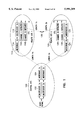
- FIG. 1 is a block diagram of one environment in which the present bandwidth management system may be practiced
- FIG. 2A shows a frequency spectrum of a first composite signal
- FIG. 2B shows a frequency spectrum of a translated version of the first composite signal in FIG. 2A
- FIG. 3 is a block diagram of one embodiment of a frequency translation system
- FIG. 4 is a block diagram of one embodiment of a frequency translation system
- FIG. 5 is a block diagram of one embodiment of a frequency translation system
- FIG. 6A shows a frequency spectrum of a first composite signal
- FIG. 6B shows a frequency spectrum of an output from a mixer having an input signal as shown in FIG. 6A;
- FIG. 6C shows the frequency spectrum after filtering
- FIG. 6D shows the frequency spectrum after mixing a second time
- FIG. 7A shows a frequency spectrum of a first composite signal
- FIG. 7B shows a converted frequency spectrum of the first signal
- FIG. 8A shows the lower frequency portion of the first signal
- FIG. 8B shows a mixed version of the lower frequency portion
- FIG. 8C shows a filtered version of the mixed version of FIG. 8B
- FIG. 9A shows a block diagram of one embodiment of an upeonversion system
- FIG. 9B shows a block diagram of one embodiment of a downconversion system
- FIG. 10 shows a block diagram of one embodiment of a mixer system for upeonversion
- FIG. 11 shows a block diagram of one embodiment of a mixer system for downconversion
- FIG. 12 shows a block diagram of one embodiment of a mixer system for upconversion
- FIG. 13 shows a block diagram of one embodiment of a mixer system for down conversion
- FIG. 14 shows signal timing according to one embodiment of the reconstruction system.
- the bandwidth management system is described using an example of a repeater-based system having subaudible signalling which is not within the passband of a microwave multiplexer. Therefore, the embodiments herein describe a system for positioning the subaudible signalling within the passband of the microwave multiplexer.
- these examples are for purposes of demonstrating the present bandwidth management system, and are not intended in a limiting or exclusive sense.
- the present bandwidth management system is also applicable for any signal bandwidth management application, and the use of the present system in a repeater network is intended to demonstrate the present system and is not intended in a limiting or exclusive sense.
- the present bandwidth management system is also applicable for performing different spectral translations, such as multiband, low pass, and high pass signal translation.
- FIG. 1 shows one environment in which the present invention may be practiced.
- two remote repeater sites 110 and 120 are in communication with central site 100 over the microwave equipment including transceivers 104, 114, and 124 and multiplexers 102, 112, and 122.
- Other links may be used without departing from the scope of the present invention.
- the system in FIG. 1 shows two channels, A and B, to demonstrate the present system. Other numbers of channels are possible without departing from the scope of the present invention.
- Mobile transceivers (not shown in FIG. 1) communicate with the repeater site which provides the best signal.
- Inter-site communications are possible using a system of subaudible signalling, such as the system described in U.S. Pat. No. 5,159,701, entitled “METHOD AND APPARATUS FOR A DISTRIBUTIVE WIDE AREA NETWORK FOR A LAND MOBILE TRANSMISSION TRUNKED COMMUNICATION SYSTEM", which is hereby incorporated by reference.
- subaudible tones are used to transmit control signals to facilitate inter-repeater communications.
- control data In such a trunked radio system the spectral content of the control data typically extends from nearly DC to 300 Hz.
- the control data is transmitted with voice information, data information, or both.
- the control information transmitted by central site 100 provides commands and information to the radio units serviced by repeater sites 110 and 120.
- control information having a bandwidth of approximately DC to 300 Hz is generated at central site 100 and must be communicated, along with a 300 Hz to 3000 Hz audio signal, to the repeater sites 110 and 120.
- Other spectral subdivisions may be managed by the present bandwidth management system without departing from the spirit and scope of the present invention, and the present system is not limited to the stated frequency subdivisions.
- the present bandwidth management system allows the use of existing link equipment, whose passband extends from 300 Hz to 3400 Hz.
- the use of existing equipment allows flexibility in the design of systems since many companies can supply such equipment. Using existing, rather than specially designed, and therefore more costly, equipment also reduces overall system cost.
- the passband extends from 300 Hz to 3400 Hz, however the information we wish to pass consists of a high frequency component which extends from 300 Hz to 3000 Hz, and a low frequency component which extends from nearly DC to approximately 300 Hz.
- the low frequency component is a data signal
- the high frequency component is an audio signal.
- FIG. 2A shows the original composite signal and the passband of the existing multiplexing equipment. It is apparent that the data signal will not be passed by the existing multiplexing equipment. If the entire composite signal is shifted upband by 300 Hz, then the entire composite signal falls within the passband of the existing multiplexing equipment.
- the whole signal spectrum (composite signal) is translated upband by 300 Hz.
- the data signal extends from 300 Hz to 600 Hz and the audio signal extends from 600 Hz to the top of the multiplexer passband. If the multiplexer passband is less than 3300 Hz, then the upper portion of the audio signal will be attenuated. This compromise may be acceptable for the benefit of transferring the data signal. Shifting the entire spectrum up by 300 Hz provides the same amount of isolation between the data and audio signals as exhibited by the composite signal.
- fy is equal to the amount of frequency shift desired for the input signal x(t)/2.
- fy is equal to a 300 Hz tone is used to translate the x(t)/2 input signal, which is the composite signal, upband by 300 Hz.
- Other tone frequencies may be used to translate the composite signal to different frequencies. Therefore, if the composite signal, shown in FIG. 2A, is the input signal, x(t)/2, then the output signal using a 300 Hz tone is shown in FIG. 2B.
- FIG. 4 Another system for translating the composite signal is demonstrated by FIG. 4, which uses Weaver's method to translate the composite signal in frequency.
- the x(t) signal is the composite signal.
- the frequencies of f1 is set to 3000 Hz
- f2 is 3300 Hz, so that f1-f2 is equal to the desired frequency shift.
- the low pass filter bandwidth is equal to f1 (3000 Hz in this example).
- Other frequencies may be used as long as the difference between f1 and f2 is equal to the desired frequency shift.
- FIG. 5 Yet another system of translating the composite signal is a double mixing system as shown in FIG. 5.
- the composite signal of FIG. 2A also shown in FIG. 6A, is translated upband by 3000 Hz by setting f1 to 3000 Hz and mixing it with the input signal.
- the resulting signal is shown in FIG. 6B.
- Filter 1 is a high pass or band pass filter which is used to produce the signal of FIG. 6C.
- This signal is then translated to 300 Hz by mixing it with a 2700 Hz signal as f2.
- the resulting signal is filtered with a low pass filter or band pass filter to remove the 5.7 KHz signal component.
- the final signal is shown in FIG. 2B.
- the central site 100 contains a system which translates the data signal such that it resides above 3000 Hz but below 3400 Hz, so that it is within the passband of the multiplexer 112 (or 122). This is illustrated in FIGS. 7A and 7B.
- the data signal is shifted back to its original spectral position ("reconstructed") before the composite signal, consisting of the audio signal and data signal, is transmitted to the radios in the field (not shown).
- FIGS. 8A, 8B, and 8C One method for upband translation of the data signal is shown in FIGS. 8A, 8B, and 8C.
- a single frequency will represent the data signal translated.
- the data spectrum is a Fourier series of single frequency signals, whose summation reproduces the time domain form of the data signal.
- cos (2 ⁇ f x t) to be representative of the data signal.
- Multiplying the data signal by another tone, such as cos (2 ⁇ 3000t) gives 0.5 cos (2 ⁇ [3000-f x ]t)+0.5 cos (2 ⁇ [3000+f x ]t).
- the data signal now has the form of a double sideband signal whose center frequency is higher than the original data frequency, as illustrated in FIG. 8B.
- the lower sideband Before adding the audio signal to the upband translated data signal for transmission through the multiplexer the lower sideband, is eliminated using a highpass filter. In an alternate embodiment a bandpass filter is used to eliminate the lower sideband.
- the upper sideband shown in FIG. 8C, may now be added to the audio signal which extends from 300 Hz to 3000 Hz. The resulting combined signal extends from 300 Hz to 3300 Hz, as shown in FIG. 7B.
- FIG. 9A One system for performing the upband frequency translations described is shown in FIG. 9A.
- the input signal cos (2 ⁇ f x t), which is representative of the data signal, is multiplied by the tone, cos (2 ⁇ 3000t), to produce the signal of FIG. 8B.
- the filter removes the lower sideband to generate the signal of FIG. 8C.
- the inverse of this method is applied at the remote site to move the data spectrum back to its original position, as shown in FIG. 7A.
- Multiplying the data signal, represented by cos (2 ⁇ [3000+f x ]t) by cos (2 ⁇ 3000t) produces 0.5 cos (2 ⁇ ft)+0.5 cos (2 ⁇ 6000t).
- the second term is removed using a lowpass filter, and the original data signal represented by the first term is recovered.
- FIG. 9B One system used to perform the down frequency translation is shown in FIG. 9B.
- FIG. 10 shows one system for translating the data signal upband of the audio signal, however, the shifting process does not create a double sideband signal which requires filtering, as in the last embodiment.
- the output signal, y(t), in FIG. 10 is: ##EQU1## where x(t) is the quadrature signal obtained by phase shifting all components of x(t) by 90 degrees. To understand that this signal does indeed represent a single sideband of x(t) shifted upband by 3000 Hz, we write: ##EQU2## where, for our case, we make the restriction f i ⁇ 300 Hz.
- the desired single sideband signal is: ##EQU3## which can be rewritten as: ##EQU4## This embodiment requires wideband 90 degree phase shifting, which can be difficult to design and implement and tends to distort low frequency signal components.
- the inverse of this system is applied to the problem of returning the data to its original spectral position (i.e., FIG. 8A).
- the upband translated data spectrum i.e. ##EQU5## which is equal to ##EQU6## is the input signal on the left side of FIG. 10.
- the system shown in FIG. 11 is used.
- the output is then ⁇ X i cos (2 ⁇ f i +0 i ), which was the original data signal, as shown in FIG. 8A.
- the audio signal may then be added to the data signal to reconstruct the original composite signal, as shown in FIG. 7A.
- FIG. 12 shows another system for performing the upband translation of the data signal using Weaver's method.
- the signal will be a Fourier series of frequencies which correspond to the time domain version of the data signal.
- the signals at points (a) and (b) are: ##EQU7## respectively.
- Low pass filtering with a corner frequency of f 1 removes the sum frequency terms, leaving the signals at (c) and (d) as ##EQU8## and ##EQU9## respectively.
- the signals at (e) and (f) are: ##EQU10## respectively.
- this system is used to down translate the data signal spectrum.
- the input signal is cos [2 ⁇ (f x -f 1 +f 2 )t], which is mixed with the frequency f 2 , lowpass filtered with bandwidth f 1 , mixed with f 1 , and then summed.
- the output is cos (2 ⁇ f x t) which is the original data signal.
- the only difference between moving the data upband and moving it downband is the order in which the mixing frequencies are applied. For upband translation the first mix is with f 1 then f 2 , while the opposite order is used for the downband translation process.
- the system of FIG. 12 is used to move the data spectrum upband so it will be passed by existing multiplexer equipment while the system of FIG. 11 is used to perform the downband translation.
- the system of FIG. 11 is used to perform the downband translation.
- any combination of the described embodiments, and their equivalents, may be combined. These embodiments may be implemented with either digital signal processing software or using actual circuit elements.
- An additional embodiment of the present invention provides a system whereby the deconversion of the translated spectrum is coordinated to minimize distortions in the reconstructed signals.
- This embodiment is particularly useful is in a simulcast system.
- Simulcast systems have remote receivers which demodulate two or more signals in overlapping broadcast regions. Distortions in the reconstructed signals complicate demodulation by a receiver in the overlap area.
- One example of a simulcast broadcast system is described in the copending patent application filed even date herewith entitled "SIMULTANEOUS BROADCAST MANAGEMENT SYSTEM", which is hereby incorporated by reference.
- the upband translation process takes place at the central site 100.
- the signal is then transmitted over multiplexer 102 and microwave equipment 104 to a remote site, for example, remote site 110.
- This transmission takes some amount of time t link due to the time required to propagate a signal from the central site 100 to the remote site 110 as well as time delays associated with the multiplexers 102 and 112 and microwave equipment 104 and 114.
- This time delay means there is an associated phase delay which is:
- the data signal received at the remote site 110 is, therefore, cos (2 ⁇ [3000+f x ]t+ ⁇ link ).
- This signal must be moved back to its original spectral position. Doing so requires mixing it with a tone of frequency 3000 Hz since, for this example, the data spectrum was moved up by 3000 Hz.
- GPS global positioning system
- the signals cos (2 ⁇ [3000+f x ]t+ ⁇ link ) and cos (2 ⁇ 3000t+ ⁇ ), are mixed at the remote site 110, as shown in FIG. 13.
- the phase term ⁇ represents the phase relationship between the tones, since synchronization of the mixing frequencies to both be 3000 Hz does not determine the phase relationship between these tones. That is, the 3000 Hz tone at the remote site 110 is generally an unknown number of degrees out of phase with respect to the 3000 Hz tone at the central site 100.
- phase is not controlled at the remote site, i.e. ⁇ , then the correct data frequency f x is recovered, but there is an unknown phase shift [ ⁇ link - ⁇ ].
- This phase shift causes difficulty in recovering the data signal, since the actual data signal is in reality represented by a Fourier series sum of tones. Those tones have certain phase relationships with respect to each other. If that phase relationship is corrupted, which is what occurs if we do not control ⁇ , then when summing the tones the original data signal is not properly reconstructed. We must, therefore, ensure that [ ⁇ link - ⁇ ] is minimized.
- the tone at the remote site is then passed through a variable phase (time) delay which is set to ⁇ link before it is mixed with the upband translated data.
- This phase adjusted signal is the cos (2 ⁇ 3000t+ ⁇ ) signal of FIG. 13. This ensures that the data waveform will be properly reconstructed.
- phase offset i.e. [ ⁇ link - ⁇ ].
- a decision based recovery method where the received signal is used to determine what data has been sent.
- this method suffers the drawback that the recovery produces jitter due to the ambiguity of when the data changes state. If this ambiguity is too large they may sum at each location in such a way as to produce a large offset and provide unacceptable data distortion in the simulcast region.
- pilot tone Another approach is to transmit a pilot tone, along with the data signal, that indicates when state changes occur. This requires that some signal energy of the audio signal and data signal be sacrificed. Performance will suffer since the noise floor will increase because the channel energy is finite.
- a pilot tone also increases the DSP filtering complexity and affects system timing.
- One approach is to derive system synchronization using an outside source GPS.
- the GPS provides fixed one pulse per second and 10 MHz clocks that can be used to provide the required synchronization.
- the transmitting and receiving ends both use modulation frequencies that are integers to insure that they divide into one second without remainder. That is, f2 is required to be an integer.
- Each site begins generating a tone of frequency f 2 on a one second boundary, as shown in FIG. 14, so that all sites are phase aligned. It should be noticed that the f 2 frequencies at the channel controller and the remote site do not have to be equal. They both, however, reach zero at the one second mark, as illustrated.
- GPS synchronization may be applied to any of the frequency conversion methods described herein.
- the present system applies in situations where the frequency translations are different and any combination of the systems taught herein may be adapted for a variety of different systems.
Abstract
Description
φ.sub.link (in degrees)=t.sub.link 360(3000+f.sub.x) Eqn. 11
0.5 cos (2πf.sub.x t+[φ.sub.link -φ])+0.5 cos (2π[6000+f.sub.x ]t+[φ.sub.link +φ]) Eqn. 12
Claims (12)
Priority Applications (9)
| Application Number | Priority Date | Filing Date | Title |
|---|---|---|---|
| US08/628,981 US5991309A (en) | 1996-04-12 | 1996-04-12 | Bandwidth management system for a remote repeater network |
| AU24502/97A AU2450297A (en) | 1996-04-12 | 1997-04-11 | Simultaneous broadcast management system |
| AU26629/97A AU2662997A (en) | 1996-04-12 | 1997-04-11 | Transmit control system using control tone signalling |
| PCT/US1997/005984 WO1997039543A2 (en) | 1996-04-12 | 1997-04-11 | Link delay calculation system for a radio repeater system |
| AU27262/97A AU2726297A (en) | 1996-04-12 | 1997-04-11 | Link delay calculation system for a radio repeater system |
| PCT/US1997/005985 WO1997039535A2 (en) | 1996-04-12 | 1997-04-11 | Bandwidth management system for a remote repeater network |
| PCT/US1997/005893 WO1997039541A1 (en) | 1996-04-12 | 1997-04-11 | Transmit control system using control tone signalling |
| AU27263/97A AU2726397A (en) | 1996-04-12 | 1997-04-11 | Bandwidth management system for a remote repeater network |
| PCT/US1997/005891 WO1997039542A2 (en) | 1996-04-12 | 1997-04-11 | Simultaneous broadcast management system |
Applications Claiming Priority (1)
| Application Number | Priority Date | Filing Date | Title |
|---|---|---|---|
| US08/628,981 US5991309A (en) | 1996-04-12 | 1996-04-12 | Bandwidth management system for a remote repeater network |
Publications (1)
| Publication Number | Publication Date |
|---|---|
| US5991309A true US5991309A (en) | 1999-11-23 |
Family
ID=24521108
Family Applications (1)
| Application Number | Title | Priority Date | Filing Date |
|---|---|---|---|
| US08/628,981 Expired - Lifetime US5991309A (en) | 1996-04-12 | 1996-04-12 | Bandwidth management system for a remote repeater network |
Country Status (1)
| Country | Link |
|---|---|
| US (1) | US5991309A (en) |
Cited By (21)
| Publication number | Priority date | Publication date | Assignee | Title |
|---|---|---|---|---|
| WO2000051371A1 (en) * | 1999-02-23 | 2000-08-31 | Conexant Systems, Inc. | System and process for shared functional block communication transceivers with gps capability |
| US6181715B1 (en) * | 1999-05-27 | 2001-01-30 | Qwest Communications International Inc. | Method and system for providing emulated telephony over DSL |
| US6304216B1 (en) | 1999-03-30 | 2001-10-16 | Conexant Systems, Inc. | Signal detector employing correlation analysis of non-uniform and disjoint sample segments |
| US6327471B1 (en) | 1998-02-19 | 2001-12-04 | Conexant Systems, Inc. | Method and an apparatus for positioning system assisted cellular radiotelephone handoff and dropoff |
| WO2002011470A1 (en) * | 2000-08-02 | 2002-02-07 | Conexant Systems, Inc. | Block communication transceivers with gps capability |
| US6348744B1 (en) | 1998-04-14 | 2002-02-19 | Conexant Systems, Inc. | Integrated power management module |
| US6448925B1 (en) | 1999-02-04 | 2002-09-10 | Conexant Systems, Inc. | Jamming detection and blanking for GPS receivers |
| US20020128044A1 (en) * | 2001-01-19 | 2002-09-12 | Chang Donald C.D. | Communication system for mobile users using adaptive antenna |
| US6496145B2 (en) | 1999-03-30 | 2002-12-17 | Sirf Technology, Inc. | Signal detector employing coherent integration |
| US6519277B2 (en) | 1999-05-25 | 2003-02-11 | Sirf Technology, Inc. | Accelerated selection of a base station in a wireless communication system |
| US6531982B1 (en) | 1997-09-30 | 2003-03-11 | Sirf Technology, Inc. | Field unit for use in a GPS system |
| US6606349B1 (en) | 1999-02-04 | 2003-08-12 | Sirf Technology, Inc. | Spread spectrum receiver performance improvement |
| US6693953B2 (en) | 1998-09-30 | 2004-02-17 | Skyworks Solutions, Inc. | Adaptive wireless communication receiver |
| US6714158B1 (en) | 2000-04-18 | 2004-03-30 | Sirf Technology, Inc. | Method and system for data detection in a global positioning system satellite receiver |
| US6778136B2 (en) | 2001-12-13 | 2004-08-17 | Sirf Technology, Inc. | Fast acquisition of GPS signal |
| US6788655B1 (en) | 2000-04-18 | 2004-09-07 | Sirf Technology, Inc. | Personal communications device with ratio counter |
| US7711038B1 (en) | 1998-09-01 | 2010-05-04 | Sirf Technology, Inc. | System and method for despreading in a spread spectrum matched filter |
| US7852905B2 (en) | 1998-09-01 | 2010-12-14 | Sirf Technology, Inc. | System and method for despreading in a spread spectrum matched filter |
| US7885314B1 (en) | 2000-05-02 | 2011-02-08 | Kenneth Scott Walley | Cancellation system and method for a wireless positioning system |
| US7929984B2 (en) * | 2001-01-19 | 2011-04-19 | The Directv Group, Inc. | Multiple basestation communication system having adaptive antennas |
| US10986164B2 (en) | 2004-01-13 | 2021-04-20 | May Patents Ltd. | Information device |
Citations (91)
| Publication number | Priority date | Publication date | Assignee | Title |
|---|---|---|---|---|
| NL6508593A (en) * | 1965-07-02 | 1967-01-03 | ||
| US3867700A (en) * | 1972-11-15 | 1975-02-18 | Keith H Wycoff | Tone operated single side-band communication system |
| US4085368A (en) * | 1976-08-30 | 1978-04-18 | Bell Telephone Laboratories, Incorporated | Interference canceling method and apparatus |
| US4125744A (en) * | 1948-12-24 | 1978-11-14 | Bell Telephone Laboratories, Incorporated | Communication system |
| US4131849A (en) * | 1976-10-21 | 1978-12-26 | Motorola, Inc. | Two-way mobile radio voice/data shared communications system |
| US4131850A (en) * | 1977-02-18 | 1978-12-26 | Glade Wilcox | Single side band radio apparatus |
| EP0004702A1 (en) * | 1978-04-10 | 1979-10-17 | Motorola, Inc. | Simulcast transmission system having phase-locked remote transmitters |
| GB1574599A (en) * | 1977-04-20 | 1980-09-10 | Plessey Co Ltd | Fault indication in repeatered telecommunications transmission-line |
| EP0020893A1 (en) * | 1979-06-08 | 1981-01-07 | Robert Bosch Gmbh | Radio network |
| US4255620A (en) * | 1978-01-09 | 1981-03-10 | Vbc, Inc. | Method and apparatus for bandwidth reduction |
| US4281413A (en) * | 1979-12-03 | 1981-07-28 | General Electric Company | Multichannel radio telephone system |
| US4325057A (en) * | 1980-06-30 | 1982-04-13 | Bishop-Hall, Inc. | School bus approach notification method and apparatus |
| DE3203678A1 (en) * | 1982-02-04 | 1983-08-11 | Licentia Patent-Verwaltungs-Gmbh, 6000 Frankfurt | Common-frequency radio network |
| US4406016A (en) * | 1981-11-27 | 1983-09-20 | The United States Of America As Represented By The Secretary Of The Army | VHF Sensor in-band radio relay |
| US4490830A (en) * | 1981-07-22 | 1984-12-25 | Nippon Electric Co., Ltd. | Radio signal transmission system including a plurality of transmitters for transmitting a common signal |
| US4516269A (en) * | 1982-12-10 | 1985-05-07 | Michigan Consolidated Gas Company | Automatic equalization for a simulcast communication system |
| US4608686A (en) * | 1982-02-22 | 1986-08-26 | Mitel Corporation | Two wire voice and data subscriber loop |
| US4679243A (en) * | 1984-08-17 | 1987-07-07 | National Research Development Corporation | Data transmission using a transparent tone-in band system |
| US4696052A (en) * | 1985-12-31 | 1987-09-22 | Motorola Inc. | Simulcast transmitter apparatus having automatic synchronization capability |
| US4696051A (en) * | 1985-12-31 | 1987-09-22 | Motorola Inc. | Simulcast transmission system having automtic synchronization |
| US4726069A (en) * | 1984-05-18 | 1988-02-16 | Stevenson Carl R | A muiti-mode modulation and demodulation system and method |
| US4802191A (en) * | 1986-02-28 | 1989-01-31 | National Research Development Corporation | Data transmission using a transparent tone-in band system |
| US4803739A (en) * | 1984-12-10 | 1989-02-07 | Nippon Telegraph And Telegraph Corporation | SSB communication system |
| US4852090A (en) * | 1987-02-02 | 1989-07-25 | Motorola, Inc. | TDMA communications system with adaptive equalization |
| US4862098A (en) * | 1988-05-04 | 1989-08-29 | General Electric Company | Continuous-wave-modulation detectors using prediction methods |
| US4903292A (en) * | 1988-11-01 | 1990-02-20 | Reliance Comm/Tec Corporation | System for transmitting low frequency tones through a digital loop carrier system |
| US4972410A (en) * | 1989-07-20 | 1990-11-20 | Electrocom Automation, Inc. | Method and apparatus for controlling signal coherency in simulcast systems |
| US4994804A (en) * | 1988-03-15 | 1991-02-19 | Kabushiki Kaisha Toshiba | Double integration delta-sigma modulation analog to digital converter |
| US5003617A (en) * | 1988-10-21 | 1991-03-26 | Motorola, Inc. | Simulcast broadcasting system and method |
| US5038403A (en) * | 1990-01-08 | 1991-08-06 | Motorola, Inc. | Simulcast system with minimal delay dispersion and optimal power contouring |
| US5060240A (en) * | 1989-02-14 | 1991-10-22 | Motorola, Inc. | Simulcast system and channel unit |
| US5061934A (en) * | 1990-11-09 | 1991-10-29 | The United States Of America As Represented By The Secretary Of The Air Force | Hybrid clutter cancellation method and system for improved radar performance |
| US5077759A (en) * | 1988-02-10 | 1991-12-31 | Nec Corporation | Phase adjusting system for a radio communication system |
| US5105439A (en) * | 1989-08-11 | 1992-04-14 | Motorola, Inc. | Delay equalization detector |
| US5113413A (en) * | 1989-06-09 | 1992-05-12 | Ericsson Ge Mobile Communications Inc. | Voter arrangement for multiple site PST RF trunking system |
| US5117503A (en) * | 1989-10-02 | 1992-05-26 | Motorola, Inc. | Directional antenna arrangement method for simulcast broadcasting |
| US5117424A (en) * | 1989-07-20 | 1992-05-26 | Electrocom Automation L.P. | Method and apparatus for setting clock signals to predetermined phases at remote broadcast sites in simulcast systems |
| US5127101A (en) * | 1991-02-01 | 1992-06-30 | Ericsson Ge Mobile Communications Inc. | Simulcast auto alignment system |
| US5128934A (en) * | 1990-06-29 | 1992-07-07 | Motorola, Inc. | Multiple transmitter message transmission system and method therefor |
| US5131010A (en) * | 1989-10-12 | 1992-07-14 | General Electric Company | Voice guard digital voter for multiple site PST RF trunking system |
| US5134630A (en) * | 1989-04-12 | 1992-07-28 | National Research Development Corporation | Method and apparatus for transparent tone-in-band transmitter, receiver and system processing |
| USRE34036E (en) * | 1984-06-06 | 1992-08-18 | National Research Development Corporation | Data transmission using a transparent tone-in band system |
| US5142692A (en) * | 1989-06-16 | 1992-08-25 | Seiko Corp. | Transmitting information with cut and flip spectrum |
| US5155859A (en) * | 1991-03-28 | 1992-10-13 | Motorola, Inc. | Simulcast transmission system having automatic audio equalization |
| EP0515214A1 (en) * | 1991-05-24 | 1992-11-25 | BRITISH TELECOMMUNICATIONS public limited company | Radio system with measurement and adjustment of transfer delay |
| US5172396A (en) * | 1988-10-20 | 1992-12-15 | General Electric Company | Public service trunking simulcast system |
| US5184242A (en) * | 1989-12-15 | 1993-02-02 | Nec Corporation | Supervisory circuit for optical repeater |
| US5194871A (en) * | 1982-03-01 | 1993-03-16 | Western Atlas International, Inc. | System for simultaneously deriving position information from a plurality of satellite transmissions |
| US5201061A (en) * | 1990-07-23 | 1993-04-06 | Motorola, Inc. | Method and apparatus for synchronizing simulcast systems |
| WO1993007681A1 (en) * | 1991-10-04 | 1993-04-15 | Motorola, Inc. | Simulcast synchronization and equalization system and method therefor |
| US5212807A (en) * | 1991-03-28 | 1993-05-18 | Motorola, Inc. | Method of automatic path map generation for simulcast transmission system |
| US5218717A (en) * | 1990-01-10 | 1993-06-08 | Rohde & Schwarz Gmbh & Co. Kg | Simulcast transmission system with improved synchronizing system |
| US5218621A (en) * | 1991-04-04 | 1993-06-08 | Motorola, Inc. | Adaptive digital equalization filter |
| WO1993011614A1 (en) * | 1991-12-06 | 1993-06-10 | Motorola, Inc. | Technique for measuring channel delay |
| US5227741A (en) * | 1992-01-22 | 1993-07-13 | Glenayre Electronics Ltd. | Variable speed asynchronous modem |
| EP0551126A1 (en) * | 1992-01-10 | 1993-07-14 | Nec Corporation | Simulcast radio paging system |
| US5239672A (en) * | 1991-06-28 | 1993-08-24 | Motorola, Inc. | Synchronization method and apparatus for simulcast transmission system |
| US5243299A (en) * | 1992-01-22 | 1993-09-07 | Glenayre Electronics, Inc. | Variable speed asynchronous modem |
| US5261118A (en) * | 1991-10-04 | 1993-11-09 | Motorola, Inc. | Simulcast synchronization and equalization system and method therefor |
| US5287550A (en) * | 1990-12-24 | 1994-02-15 | Motorola, Inc. | Simulcast scheduler |
| US5295178A (en) * | 1990-12-03 | 1994-03-15 | Ericsson Ge Mobile Communications Inc. | Digital signal processor for radio base station |
| US5319374A (en) * | 1993-02-02 | 1994-06-07 | Trimble Navigation Limited | Precise universal time for vehicles |
| US5327581A (en) * | 1992-05-29 | 1994-07-05 | Motorola, Inc. | Method and apparatus for maintaining synchronization in a simulcast system |
| US5353307A (en) * | 1991-09-03 | 1994-10-04 | General Electric Company | Automatic simulcast alignment |
| US5353342A (en) * | 1992-12-08 | 1994-10-04 | Bell Communications Research, Inc. | Adaptive multitone signaling method |
| US5361398A (en) * | 1993-01-29 | 1994-11-01 | Motorola, Inc. | Method and apparatus for transmission path delay measurements using adaptive demodulation |
| US5365569A (en) * | 1992-08-17 | 1994-11-15 | Glenayre Electronics, Ltd. | Digital simulcast transmission system |
| US5369682A (en) * | 1992-08-17 | 1994-11-29 | Glenayre Electronics, Inc. | Digital simulcast transmission system |
| US5392278A (en) * | 1990-08-28 | 1995-02-21 | Ericsson Ge Mobile Communications Inc. | Distributed multisite system architecture |
| US5398263A (en) * | 1993-01-14 | 1995-03-14 | Motorola, Inc. | Autonomous pulse train timing controls for time-mark alignment |
| US5408681A (en) * | 1993-08-16 | 1995-04-18 | The United States Of America As Represented By The Secretary Of The Navy | Automatic repeater station for signal transmissions |
| US5414734A (en) * | 1993-01-06 | 1995-05-09 | Glenayre Electronics, Inc. | Compensation for multi-path interference using pilot symbols |
| US5416808A (en) * | 1992-03-31 | 1995-05-16 | Glenayre Electronics, Inc. | Apparatus for synchronizing a plurality of clocks in a simulcast network to a reference clock |
| US5423059A (en) * | 1993-07-29 | 1995-06-06 | Motorola Inc. | Method for enhancing signal quality in a simulcast communication system |
| US5423056A (en) * | 1991-02-25 | 1995-06-06 | Pagemart, Inc. | Adaptive cellular paging system |
| US5423058A (en) * | 1992-10-05 | 1995-06-06 | Motorola, Inc. | Simulcast transmission system with selective call tones |
| US5440313A (en) * | 1993-05-27 | 1995-08-08 | Stellar Gps Corporation | GPS synchronized frequency/time source |
| US5448758A (en) * | 1993-02-26 | 1995-09-05 | Motorola, Inc. | Simulcast group determination of best signal by master site |
| US5448570A (en) * | 1993-03-17 | 1995-09-05 | Kyocera Corporation | System for mutual synchronization and monitoring between base stations |
| US5465405A (en) * | 1992-07-30 | 1995-11-07 | Raytheon Company | Apparatus and method for detecting signals |
| US5473638A (en) * | 1993-01-06 | 1995-12-05 | Glenayre Electronics, Inc. | Digital signal processor delay equalization for use in a paging system |
| US5477539A (en) * | 1993-07-23 | 1995-12-19 | Ericsson Inc. | Narrow band simulcast system having low speed data distribution |
| US5481258A (en) * | 1993-08-11 | 1996-01-02 | Glenayre Electronics, Inc. | Method and apparatus for coordinating clocks in a simulcast network |
| US5483670A (en) * | 1987-06-03 | 1996-01-09 | Ericsson Ge Mobile Communications Inc. | Trunked radio repeater system with control channel monitoring feature |
| US5483575A (en) * | 1993-02-19 | 1996-01-09 | Ericsson Ge Mobile Communications Inc. | System for correlating RF usage in a trunked communication network based on channel assignments and channel drops for each call |
| US5490172A (en) * | 1994-07-05 | 1996-02-06 | Airnet Communications Corporation | Reducing peak-to-average variance of a composite transmitted signal via out-of-band artifact signaling |
| US5513215A (en) * | 1993-09-20 | 1996-04-30 | Glenayre Electronics, Inc. | High speed simulcast data system using adaptive compensation |
| US5555546A (en) * | 1994-06-20 | 1996-09-10 | Kokusai Electric Co., Ltd. | Apparatus for decoding a DPCM encoded signal |
| US5590403A (en) * | 1992-11-12 | 1996-12-31 | Destineer Corporation | Method and system for efficiently providing two way communication between a central network and mobile unit |
| US5619564A (en) * | 1995-05-31 | 1997-04-08 | Lucent Technologies Inc. | Tone detector with improved performance in the presence of speech |
| US5668836A (en) * | 1994-12-29 | 1997-09-16 | Motorola, Inc. | Split frequency band signal digitizer and method |
-
1996
- 1996-04-12 US US08/628,981 patent/US5991309A/en not_active Expired - Lifetime
Patent Citations (95)
| Publication number | Priority date | Publication date | Assignee | Title |
|---|---|---|---|---|
| US4125744A (en) * | 1948-12-24 | 1978-11-14 | Bell Telephone Laboratories, Incorporated | Communication system |
| NL6508593A (en) * | 1965-07-02 | 1967-01-03 | ||
| US3867700A (en) * | 1972-11-15 | 1975-02-18 | Keith H Wycoff | Tone operated single side-band communication system |
| US4085368A (en) * | 1976-08-30 | 1978-04-18 | Bell Telephone Laboratories, Incorporated | Interference canceling method and apparatus |
| US4131849A (en) * | 1976-10-21 | 1978-12-26 | Motorola, Inc. | Two-way mobile radio voice/data shared communications system |
| US4131850A (en) * | 1977-02-18 | 1978-12-26 | Glade Wilcox | Single side band radio apparatus |
| GB1574599A (en) * | 1977-04-20 | 1980-09-10 | Plessey Co Ltd | Fault indication in repeatered telecommunications transmission-line |
| US4255620A (en) * | 1978-01-09 | 1981-03-10 | Vbc, Inc. | Method and apparatus for bandwidth reduction |
| EP0004702A1 (en) * | 1978-04-10 | 1979-10-17 | Motorola, Inc. | Simulcast transmission system having phase-locked remote transmitters |
| EP0020893A1 (en) * | 1979-06-08 | 1981-01-07 | Robert Bosch Gmbh | Radio network |
| US4281413A (en) * | 1979-12-03 | 1981-07-28 | General Electric Company | Multichannel radio telephone system |
| US4325057A (en) * | 1980-06-30 | 1982-04-13 | Bishop-Hall, Inc. | School bus approach notification method and apparatus |
| US4490830A (en) * | 1981-07-22 | 1984-12-25 | Nippon Electric Co., Ltd. | Radio signal transmission system including a plurality of transmitters for transmitting a common signal |
| US4406016A (en) * | 1981-11-27 | 1983-09-20 | The United States Of America As Represented By The Secretary Of The Army | VHF Sensor in-band radio relay |
| DE3203678A1 (en) * | 1982-02-04 | 1983-08-11 | Licentia Patent-Verwaltungs-Gmbh, 6000 Frankfurt | Common-frequency radio network |
| US4608686A (en) * | 1982-02-22 | 1986-08-26 | Mitel Corporation | Two wire voice and data subscriber loop |
| US5384574A (en) * | 1982-03-01 | 1995-01-24 | Western Atlas International, Inc. | System for determining position from suppressed carrier radio waves |
| US5194871A (en) * | 1982-03-01 | 1993-03-16 | Western Atlas International, Inc. | System for simultaneously deriving position information from a plurality of satellite transmissions |
| US4516269A (en) * | 1982-12-10 | 1985-05-07 | Michigan Consolidated Gas Company | Automatic equalization for a simulcast communication system |
| US4726069A (en) * | 1984-05-18 | 1988-02-16 | Stevenson Carl R | A muiti-mode modulation and demodulation system and method |
| USRE34036E (en) * | 1984-06-06 | 1992-08-18 | National Research Development Corporation | Data transmission using a transparent tone-in band system |
| US4679243A (en) * | 1984-08-17 | 1987-07-07 | National Research Development Corporation | Data transmission using a transparent tone-in band system |
| US4803739A (en) * | 1984-12-10 | 1989-02-07 | Nippon Telegraph And Telegraph Corporation | SSB communication system |
| US4696052A (en) * | 1985-12-31 | 1987-09-22 | Motorola Inc. | Simulcast transmitter apparatus having automatic synchronization capability |
| US4696051A (en) * | 1985-12-31 | 1987-09-22 | Motorola Inc. | Simulcast transmission system having automtic synchronization |
| US4802191A (en) * | 1986-02-28 | 1989-01-31 | National Research Development Corporation | Data transmission using a transparent tone-in band system |
| US4852090A (en) * | 1987-02-02 | 1989-07-25 | Motorola, Inc. | TDMA communications system with adaptive equalization |
| US5483670A (en) * | 1987-06-03 | 1996-01-09 | Ericsson Ge Mobile Communications Inc. | Trunked radio repeater system with control channel monitoring feature |
| US5077759A (en) * | 1988-02-10 | 1991-12-31 | Nec Corporation | Phase adjusting system for a radio communication system |
| US4994804A (en) * | 1988-03-15 | 1991-02-19 | Kabushiki Kaisha Toshiba | Double integration delta-sigma modulation analog to digital converter |
| US4862098A (en) * | 1988-05-04 | 1989-08-29 | General Electric Company | Continuous-wave-modulation detectors using prediction methods |
| US5172396A (en) * | 1988-10-20 | 1992-12-15 | General Electric Company | Public service trunking simulcast system |
| US5003617A (en) * | 1988-10-21 | 1991-03-26 | Motorola, Inc. | Simulcast broadcasting system and method |
| US4903292A (en) * | 1988-11-01 | 1990-02-20 | Reliance Comm/Tec Corporation | System for transmitting low frequency tones through a digital loop carrier system |
| US5060240A (en) * | 1989-02-14 | 1991-10-22 | Motorola, Inc. | Simulcast system and channel unit |
| US5134630A (en) * | 1989-04-12 | 1992-07-28 | National Research Development Corporation | Method and apparatus for transparent tone-in-band transmitter, receiver and system processing |
| US5113413A (en) * | 1989-06-09 | 1992-05-12 | Ericsson Ge Mobile Communications Inc. | Voter arrangement for multiple site PST RF trunking system |
| US5131007A (en) * | 1989-06-09 | 1992-07-14 | General Electric Company | Digital voter for multiple site PST R trunking system |
| US5142692A (en) * | 1989-06-16 | 1992-08-25 | Seiko Corp. | Transmitting information with cut and flip spectrum |
| US5117424A (en) * | 1989-07-20 | 1992-05-26 | Electrocom Automation L.P. | Method and apparatus for setting clock signals to predetermined phases at remote broadcast sites in simulcast systems |
| US4972410A (en) * | 1989-07-20 | 1990-11-20 | Electrocom Automation, Inc. | Method and apparatus for controlling signal coherency in simulcast systems |
| US5105439A (en) * | 1989-08-11 | 1992-04-14 | Motorola, Inc. | Delay equalization detector |
| US5117503A (en) * | 1989-10-02 | 1992-05-26 | Motorola, Inc. | Directional antenna arrangement method for simulcast broadcasting |
| US5131010A (en) * | 1989-10-12 | 1992-07-14 | General Electric Company | Voice guard digital voter for multiple site PST RF trunking system |
| US5184242A (en) * | 1989-12-15 | 1993-02-02 | Nec Corporation | Supervisory circuit for optical repeater |
| US5038403A (en) * | 1990-01-08 | 1991-08-06 | Motorola, Inc. | Simulcast system with minimal delay dispersion and optimal power contouring |
| US5218717A (en) * | 1990-01-10 | 1993-06-08 | Rohde & Schwarz Gmbh & Co. Kg | Simulcast transmission system with improved synchronizing system |
| US5128934A (en) * | 1990-06-29 | 1992-07-07 | Motorola, Inc. | Multiple transmitter message transmission system and method therefor |
| US5201061A (en) * | 1990-07-23 | 1993-04-06 | Motorola, Inc. | Method and apparatus for synchronizing simulcast systems |
| US5392278A (en) * | 1990-08-28 | 1995-02-21 | Ericsson Ge Mobile Communications Inc. | Distributed multisite system architecture |
| US5061934A (en) * | 1990-11-09 | 1991-10-29 | The United States Of America As Represented By The Secretary Of The Air Force | Hybrid clutter cancellation method and system for improved radar performance |
| US5295178A (en) * | 1990-12-03 | 1994-03-15 | Ericsson Ge Mobile Communications Inc. | Digital signal processor for radio base station |
| US5287550A (en) * | 1990-12-24 | 1994-02-15 | Motorola, Inc. | Simulcast scheduler |
| US5127101A (en) * | 1991-02-01 | 1992-06-30 | Ericsson Ge Mobile Communications Inc. | Simulcast auto alignment system |
| US5423056A (en) * | 1991-02-25 | 1995-06-06 | Pagemart, Inc. | Adaptive cellular paging system |
| US5212807A (en) * | 1991-03-28 | 1993-05-18 | Motorola, Inc. | Method of automatic path map generation for simulcast transmission system |
| US5155859A (en) * | 1991-03-28 | 1992-10-13 | Motorola, Inc. | Simulcast transmission system having automatic audio equalization |
| US5218621A (en) * | 1991-04-04 | 1993-06-08 | Motorola, Inc. | Adaptive digital equalization filter |
| EP0515214A1 (en) * | 1991-05-24 | 1992-11-25 | BRITISH TELECOMMUNICATIONS public limited company | Radio system with measurement and adjustment of transfer delay |
| US5239672A (en) * | 1991-06-28 | 1993-08-24 | Motorola, Inc. | Synchronization method and apparatus for simulcast transmission system |
| US5353307A (en) * | 1991-09-03 | 1994-10-04 | General Electric Company | Automatic simulcast alignment |
| US5261118A (en) * | 1991-10-04 | 1993-11-09 | Motorola, Inc. | Simulcast synchronization and equalization system and method therefor |
| WO1993007681A1 (en) * | 1991-10-04 | 1993-04-15 | Motorola, Inc. | Simulcast synchronization and equalization system and method therefor |
| US5257404A (en) * | 1991-10-04 | 1993-10-26 | Motorola, Inc. | Simulcast synchronization and equalization system and method therefor |
| WO1993011614A1 (en) * | 1991-12-06 | 1993-06-10 | Motorola, Inc. | Technique for measuring channel delay |
| US5280629A (en) * | 1991-12-06 | 1994-01-18 | Motorola, Inc. | Technique for measuring channel delay |
| EP0551126A1 (en) * | 1992-01-10 | 1993-07-14 | Nec Corporation | Simulcast radio paging system |
| US5227741A (en) * | 1992-01-22 | 1993-07-13 | Glenayre Electronics Ltd. | Variable speed asynchronous modem |
| US5243299A (en) * | 1992-01-22 | 1993-09-07 | Glenayre Electronics, Inc. | Variable speed asynchronous modem |
| US5416808A (en) * | 1992-03-31 | 1995-05-16 | Glenayre Electronics, Inc. | Apparatus for synchronizing a plurality of clocks in a simulcast network to a reference clock |
| US5327581A (en) * | 1992-05-29 | 1994-07-05 | Motorola, Inc. | Method and apparatus for maintaining synchronization in a simulcast system |
| US5465405A (en) * | 1992-07-30 | 1995-11-07 | Raytheon Company | Apparatus and method for detecting signals |
| US5369682A (en) * | 1992-08-17 | 1994-11-29 | Glenayre Electronics, Inc. | Digital simulcast transmission system |
| US5365569A (en) * | 1992-08-17 | 1994-11-15 | Glenayre Electronics, Ltd. | Digital simulcast transmission system |
| US5423058A (en) * | 1992-10-05 | 1995-06-06 | Motorola, Inc. | Simulcast transmission system with selective call tones |
| US5590403A (en) * | 1992-11-12 | 1996-12-31 | Destineer Corporation | Method and system for efficiently providing two way communication between a central network and mobile unit |
| US5353342A (en) * | 1992-12-08 | 1994-10-04 | Bell Communications Research, Inc. | Adaptive multitone signaling method |
| US5414734A (en) * | 1993-01-06 | 1995-05-09 | Glenayre Electronics, Inc. | Compensation for multi-path interference using pilot symbols |
| US5473638A (en) * | 1993-01-06 | 1995-12-05 | Glenayre Electronics, Inc. | Digital signal processor delay equalization for use in a paging system |
| US5398263A (en) * | 1993-01-14 | 1995-03-14 | Motorola, Inc. | Autonomous pulse train timing controls for time-mark alignment |
| US5361398A (en) * | 1993-01-29 | 1994-11-01 | Motorola, Inc. | Method and apparatus for transmission path delay measurements using adaptive demodulation |
| US5319374A (en) * | 1993-02-02 | 1994-06-07 | Trimble Navigation Limited | Precise universal time for vehicles |
| US5483575A (en) * | 1993-02-19 | 1996-01-09 | Ericsson Ge Mobile Communications Inc. | System for correlating RF usage in a trunked communication network based on channel assignments and channel drops for each call |
| US5448758A (en) * | 1993-02-26 | 1995-09-05 | Motorola, Inc. | Simulcast group determination of best signal by master site |
| US5448570A (en) * | 1993-03-17 | 1995-09-05 | Kyocera Corporation | System for mutual synchronization and monitoring between base stations |
| US5440313A (en) * | 1993-05-27 | 1995-08-08 | Stellar Gps Corporation | GPS synchronized frequency/time source |
| US5477539A (en) * | 1993-07-23 | 1995-12-19 | Ericsson Inc. | Narrow band simulcast system having low speed data distribution |
| US5423059A (en) * | 1993-07-29 | 1995-06-06 | Motorola Inc. | Method for enhancing signal quality in a simulcast communication system |
| US5481258A (en) * | 1993-08-11 | 1996-01-02 | Glenayre Electronics, Inc. | Method and apparatus for coordinating clocks in a simulcast network |
| US5408681A (en) * | 1993-08-16 | 1995-04-18 | The United States Of America As Represented By The Secretary Of The Navy | Automatic repeater station for signal transmissions |
| US5513215A (en) * | 1993-09-20 | 1996-04-30 | Glenayre Electronics, Inc. | High speed simulcast data system using adaptive compensation |
| US5555546A (en) * | 1994-06-20 | 1996-09-10 | Kokusai Electric Co., Ltd. | Apparatus for decoding a DPCM encoded signal |
| US5490172A (en) * | 1994-07-05 | 1996-02-06 | Airnet Communications Corporation | Reducing peak-to-average variance of a composite transmitted signal via out-of-band artifact signaling |
| US5668836A (en) * | 1994-12-29 | 1997-09-16 | Motorola, Inc. | Split frequency band signal digitizer and method |
| US5619564A (en) * | 1995-05-31 | 1997-04-08 | Lucent Technologies Inc. | Tone detector with improved performance in the presence of speech |
Non-Patent Citations (16)
| Title |
|---|
| "Digital Signal Processing Applications Using the ADSP-2100 Family", vol. 1 Prentice Hall, Inc., edited by Amy Mar, 457-465, (1992). |
| Alisouskas, Digital and Data Communications, pp: 88 89, and 119 126, 1985. * |
| Alisouskas, Digital and Data Communications, pp: 88-89, and 119-126, 1985. |
| Antoniou, Andreas, "Digital Filters: Analysis and Design," McGraw-Hill Book Company, edited by Frank J. Cerra, pp. 214-215 (1979). |
| Antoniou, Andreas, Digital Filters: Analysis and Design, McGraw Hill Book Company, edited by Frank J. Cerra, pp. 214 215 (1979). * |
| Digital Signal Processing Applications Using the ADSP 2100 Family , vol. 1 Prentice Hall, Inc., edited by Amy Mar, 457 465, (1992). * |
| Doug Hall, "DSPs ease task of detecting tones", Personal Engineering, 69-72, (Jan. 1996). |
| Doug Hall, DSPs ease task of detecting tones , Personal Engineering, 69 72, (Jan. 1996). * |
| Hattori, T., et al., "Theoretical Studies of a Simulcast Digital Radio Paging System Using a Carrier Frequency Offset Strategy", IEEE Transactions on Vehicular Technology, vol. VT-29, No. 1, pp. 87-95, (Feb. 1980). |
| Hattori, T., et al., Theoretical Studies of a Simulcast Digital Radio Paging System Using a Carrier Frequency Offset Strategy , IEEE Transactions on Vehicular Technology , vol. VT 29, No. 1, pp. 87 95, (Feb. 1980). * |
| Haykin, Simon, "Communications Systems," 2nd Edition, John Wiley & Sons, Inc., pp. 141-146 and 171-172 (1983). |
| Haykin, Simon, Communications Systems, 2nd Edition, John Wiley & Sons, Inc., pp. 141 146 and 171 172 (1983). * |
| Shanmugam, K. Sam, "Digital and Analog Communications Systems," John Wiley & Sons, Inc., pp. 268-272 and 321-322 (1979). |
| Shanmugam, K. Sam, Digital and Analog Communications Systems, John Wiley & Sons, Inc., pp. 268 272 and 321 322 (1979). * |
| Weaver, Jr.,Donald K., "A Third Method of Generation and Detection of Single-Sideband Signals," Proceedings of the IRE, pp. 1703-1705 (Dec. 1956). |
| Weaver, Jr.,Donald K., A Third Method of Generation and Detection of Single Sideband Signals, Proceedings of the IRE, pp. 1703 1705 (Dec. 1956). * |
Cited By (28)
| Publication number | Priority date | Publication date | Assignee | Title |
|---|---|---|---|---|
| US6531982B1 (en) | 1997-09-30 | 2003-03-11 | Sirf Technology, Inc. | Field unit for use in a GPS system |
| US6327471B1 (en) | 1998-02-19 | 2001-12-04 | Conexant Systems, Inc. | Method and an apparatus for positioning system assisted cellular radiotelephone handoff and dropoff |
| US6348744B1 (en) | 1998-04-14 | 2002-02-19 | Conexant Systems, Inc. | Integrated power management module |
| US7852905B2 (en) | 1998-09-01 | 2010-12-14 | Sirf Technology, Inc. | System and method for despreading in a spread spectrum matched filter |
| US7711038B1 (en) | 1998-09-01 | 2010-05-04 | Sirf Technology, Inc. | System and method for despreading in a spread spectrum matched filter |
| US6693953B2 (en) | 1998-09-30 | 2004-02-17 | Skyworks Solutions, Inc. | Adaptive wireless communication receiver |
| US6448925B1 (en) | 1999-02-04 | 2002-09-10 | Conexant Systems, Inc. | Jamming detection and blanking for GPS receivers |
| US6606349B1 (en) | 1999-02-04 | 2003-08-12 | Sirf Technology, Inc. | Spread spectrum receiver performance improvement |
| US6208844B1 (en) * | 1999-02-23 | 2001-03-27 | Conexant Systems, Inc. | System and process for shared functional block communication transceivers with GPS capability |
| WO2000051371A1 (en) * | 1999-02-23 | 2000-08-31 | Conexant Systems, Inc. | System and process for shared functional block communication transceivers with gps capability |
| US6636178B2 (en) | 1999-03-30 | 2003-10-21 | Sirf Technology, Inc. | Signal detector employing correlation analysis of non-uniform and disjoint sample segments |
| US6304216B1 (en) | 1999-03-30 | 2001-10-16 | Conexant Systems, Inc. | Signal detector employing correlation analysis of non-uniform and disjoint sample segments |
| US6577271B1 (en) | 1999-03-30 | 2003-06-10 | Sirf Technology, Inc | Signal detector employing coherent integration |
| US6496145B2 (en) | 1999-03-30 | 2002-12-17 | Sirf Technology, Inc. | Signal detector employing coherent integration |
| US6519277B2 (en) | 1999-05-25 | 2003-02-11 | Sirf Technology, Inc. | Accelerated selection of a base station in a wireless communication system |
| US6181715B1 (en) * | 1999-05-27 | 2001-01-30 | Qwest Communications International Inc. | Method and system for providing emulated telephony over DSL |
| US6714158B1 (en) | 2000-04-18 | 2004-03-30 | Sirf Technology, Inc. | Method and system for data detection in a global positioning system satellite receiver |
| US6788655B1 (en) | 2000-04-18 | 2004-09-07 | Sirf Technology, Inc. | Personal communications device with ratio counter |
| US7885314B1 (en) | 2000-05-02 | 2011-02-08 | Kenneth Scott Walley | Cancellation system and method for a wireless positioning system |
| WO2002011470A1 (en) * | 2000-08-02 | 2002-02-07 | Conexant Systems, Inc. | Block communication transceivers with gps capability |
| US20020128044A1 (en) * | 2001-01-19 | 2002-09-12 | Chang Donald C.D. | Communication system for mobile users using adaptive antenna |
| US7929984B2 (en) * | 2001-01-19 | 2011-04-19 | The Directv Group, Inc. | Multiple basestation communication system having adaptive antennas |
| US8396513B2 (en) | 2001-01-19 | 2013-03-12 | The Directv Group, Inc. | Communication system for mobile users using adaptive antenna |
| US20130172029A1 (en) * | 2001-01-19 | 2013-07-04 | The Directv Group, Inc. | Communication system for mobile users using adaptive antenna with auxiliary elements |
| US8706167B2 (en) * | 2001-01-19 | 2014-04-22 | The Directv Group, Inc. | Communication system for mobile users using adaptive antenna with auxiliary elements |
| US6778136B2 (en) | 2001-12-13 | 2004-08-17 | Sirf Technology, Inc. | Fast acquisition of GPS signal |
| US7999733B2 (en) | 2001-12-13 | 2011-08-16 | Sirf Technology Inc. | Fast reacquisition of a GPS signal |
| US10986164B2 (en) | 2004-01-13 | 2021-04-20 | May Patents Ltd. | Information device |
Similar Documents
| Publication | Publication Date | Title |
|---|---|---|
| US5991309A (en) | Bandwidth management system for a remote repeater network | |
| US4912722A (en) | Self-synchronous spread spectrum transmitter/receiver | |
| US6011952A (en) | Self-interference cancellation for relayed communication networks | |
| DE69530640T2 (en) | Mobile station for a CDMA mobile transmission system and detection method therefor | |
| JP3304683B2 (en) | Wireless device | |
| US8681916B2 (en) | Master unit, remote unit and multiband transmission system | |
| US20080056338A1 (en) | Power Line Communication Device and Method with Frequency Shifted Modem | |
| CN1612555B (en) | Modulation apparatus for reducing time delay of on-channel repeater in terrestrial digital TV broadcasting system | |
| KR100696335B1 (en) | Apparatus for transmitting radio frequency in a base station of a mobile communication system | |
| WO1997039535A2 (en) | Bandwidth management system for a remote repeater network | |
| WO1997039535A9 (en) | Bandwidth management system for a remote repeater network | |
| JPH1141159A (en) | Communication equipment | |
| US6643518B1 (en) | Method and apparatus for synchronizing telecommunications devices via a transmission network | |
| JP2848161B2 (en) | Wireless communication system | |
| EP0064728A2 (en) | Multiple phase digital modulator | |
| JPS581580B2 (en) | Multiplexed spread spectrum modulation method | |
| JP2848160B2 (en) | Wireless communication system | |
| FI112416B (en) | Method and apparatus for transmitting information by radio | |
| JP2835658B2 (en) | Transmission device | |
| JP2595751B2 (en) | Wireless transceiver | |
| JPS58197934A (en) | Spread spectrum transmitter and receiver | |
| JPH0787036A (en) | Nonregenerative relay system | |
| JP3287721B2 (en) | Communication device | |
| JP2000082986A (en) | Earth station device for fdma satellite communication | |
| JP2001274764A (en) | Digital signal transmitter |
Legal Events
| Date | Code | Title | Description |
|---|---|---|---|
| AS | Assignment |
Owner name: E.F. JOHNSON COMAPNY, MINNESOTA Free format text: ASSIGNMENT OF ASSIGNORS INTEREST;ASSIGNORS:JENSEN, DANA J.;PFIEFER, STEVEN J.;LYON, JAMES K.;AND OTHERS;REEL/FRAME:008244/0870;SIGNING DATES FROM 19960408 TO 19960409 |
|
| STCF | Information on status: patent grant |
Free format text: PATENTED CASE |
|
| CC | Certificate of correction | ||
| FPAY | Fee payment |
Year of fee payment: 4 |
|
| FEPP | Fee payment procedure |
Free format text: PAT HOLDER CLAIMS SMALL ENTITY STATUS, ENTITY STATUS SET TO SMALL (ORIGINAL EVENT CODE: LTOS); ENTITY STATUS OF PATENT OWNER: SMALL ENTITY |
|
| FPAY | Fee payment |
Year of fee payment: 8 |
|
| AS | Assignment |
Owner name: WELLS FARGO BANK, NATIONAL ASSOCIATION, CALIFORNIA Free format text: GRANT OF SECURITY INTEREST IN PATENTS;ASSIGNOR:E. F. JOHNSON COMPANY;REEL/FRAME:025017/0464 Effective date: 20100813 |
|
| FPAY | Fee payment |
Year of fee payment: 12 |
|
| AS | Assignment |
Owner name: E.F. JOHNSON COMPANY, TEXAS Free format text: RELEASE BY SECURED PARTY;ASSIGNOR:WELLS FARGO BANK, NATIONAL ASSOCIATION;REEL/FRAME:032554/0712 Effective date: 20140324 |