US5996041A - Integrated circuit memory devices having page flag cells which indicate the true or non-true state of page data therein and methods of operating the same - Google Patents

Integrated circuit memory devices having page flag cells which indicate the true or non-true state of page data therein and methods of operating the same Download PDF

Info

Publication number
US5996041A
US5996041A US08/744,437 US74443796A US5996041A US 5996041 A US5996041 A US 5996041A US 74443796 A US74443796 A US 74443796A US 5996041 A US5996041 A US 5996041A
Authority
US
United States
Prior art keywords
page
flag
data
memory
cells
Prior art date
Legal status (The legal status is an assumption and is not a legal conclusion. Google has not performed a legal analysis and makes no representation as to the accuracy of the status listed.)
Expired - Fee Related
Application number
US08/744,437
Inventor
Jin-Ki Kim
Current Assignee (The listed assignees may be inaccurate. Google has not performed a legal analysis and makes no representation or warranty as to the accuracy of the list.)
Samsung Electronics Co Ltd
Original Assignee
Samsung Electronics Co Ltd
Priority date (The priority date is an assumption and is not a legal conclusion. Google has not performed a legal analysis and makes no representation as to the accuracy of the date listed.)
Filing date
Publication date
Application filed by Samsung Electronics Co Ltd filed Critical Samsung Electronics Co Ltd
Assigned to SANSUNG ELECTRONICS CO., LTD. reassignment SANSUNG ELECTRONICS CO., LTD. ASSIGNMENT OF ASSIGNORS INTEREST (SEE DOCUMENT FOR DETAILS). Assignors: KIM, JIN-KI
Application granted granted Critical
Publication of US5996041A publication Critical patent/US5996041A/en
Anticipated expiration legal-status Critical
Expired - Fee Related legal-status Critical Current

Links

Images

Classifications

    • GPHYSICS
    • G11INFORMATION STORAGE
    • G11CSTATIC STORES
    • G11C17/00Read-only memories programmable only once; Semi-permanent stores, e.g. manually-replaceable information cards
    • GPHYSICS
    • G11INFORMATION STORAGE
    • G11CSTATIC STORES
    • G11C16/00Erasable programmable read-only memories
    • G11C16/02Erasable programmable read-only memories electrically programmable
    • G11C16/06Auxiliary circuits, e.g. for writing into memory
    • G11C16/10Programming or data input circuits
    • GPHYSICS
    • G11INFORMATION STORAGE
    • G11CSTATIC STORES
    • G11C16/00Erasable programmable read-only memories
    • G11C16/02Erasable programmable read-only memories electrically programmable
    • G11C16/06Auxiliary circuits, e.g. for writing into memory
    • G11C16/26Sensing or reading circuits; Data output circuits

Definitions

  • the present invention relates to integrated circuit memory devices, and more particularly to integrated circuit memory devices having page buffers therein.
  • Semiconductor memory devices for storing data can typically be categorized as either volatile memory devices or nonvolatile memory devices. Volatile memory devices lose their stored data when their power supplies are interrupted, however nonvolatile memory devices retain their stored data even when their power supplies are interrupted. Thus, nonvolatile memory devices are widely used in applications where the possibility of power supply interruption is present.
  • Flash EEPROM devices typically include a semiconductor substrate of first conductivity type (e.g., P-type), spaced source and drain regions of second conductivity type (e.g., N-type) in the substrate, a channel region at a face of the substrate, between the spaced source and drain regions, a floating gate for storing charge carriers when the device is programmed and a control gate which overlies the floating gate, opposite the channel region.
  • first conductivity type e.g., P-type
  • spaced source and drain regions of second conductivity type e.g., N-type
  • a floating gate for storing charge carriers when the device is programmed
  • Conventional flash EEPROM integrated circuit memory devices may contain column-by-column arrays of NAND EEPROM cells having the general construction illustrated in cross-section and schematically by FIGS.
  • Operation of a flash EEPROM device is typically divided into three modes including programming, erasing and reading.
  • Programming of a flash EEPROM device is typically achieved by biasing the drain region to a first positive bias, relative to the source region, and biasing the control gate to a second positive bias which is greater than the first positive bias.
  • these biases cause the formation of an inversion-layer channel of electrons at the face of the substrate, between the source and drain regions.
  • the drain-to-source voltage accelerates these electrons through the channel to the drain region where they acquire sufficiently large kinetic energy and are typically referred to as "hot" electrons.
  • the larger positive bias on the control gate also establishes an electrical field in a tunneling oxide layer which separates the floating gate from the channel region.
  • This electric field attracts the hot electrons and accelerates them toward the floating gate, which is disposed between the control gate and the channel region, by a process known as tunneling.
  • the floating gate then accumulates and traps the accumulated charge. Fortunately, the process of charging the floating gate is self-limiting.
  • the negative charge that accumulates on the floating gate reduces the strength of the electric field in the tunneling oxide layer to the point where it is no longer capable of accelerating "hot" electrons from the drain side of the channel region.
  • the accumulation of a large quantity of trapped charge (electrons) on the floating gate will cause the effective threshold voltage (V th ) of the field effect transistor comprising the source region, drain region, channel region and control gate to increase. If this increase is sufficiently large, the field effect transistor will remain in a nonconductive "off" state when a predetermined "read" voltage is applied to the control gate during a read operation (i.e., V th >V read ). In this state, known as the programmed state, the EEPROM device may be said to be storing a logic 0. Once programmed, the EEPROM device retains its higher threshold voltage even when its power supply is interrupted or turned off for long periods of time.
  • Erasing of the EEPROM device may also be achieved by removing the stored charge from the floating gate.
  • the erasure process can be achieved, for example, by grounding the control gate and applying a positive bias to the substrate (e.g., 10-20 Volts).
  • a positive bias e.g. 10-20 Volts.
  • Reading of the EEPROM device is achieved by applying a predetermined read voltage (V read ) to the control gate, typically via a word line connecting a row (i.e., page) of identical EEPROM devices or "cells", and applying a positive bias to the drain region, typically via a bit line connecting a column of identical EEPROM cells. If the EEPROM device is programmed, it will not conduct drain current (I ds ) and the bit line will remain at the positive bias. However, if the EEPROM device has not been programmed (or has been erased), it will heavily conduct and pull the bit lie down to ground potential (GND). In this state, the EEPROM device may be said to be storing a logic 1. Thus, by monitoring the bit line current and voltage, the programmed state (i.e., 1 or 0) of the EEPROM device can be determined.
  • V read a predetermined read voltage
  • a conventional page copy operation typically includes the steps of reading data from a first page of memory cells 101 in an array 100 to a page buffer 300 and then to a storage device 400 external to the page buffer 300. Next, the data in the storage device 400 is returned to the page buffer 300 and then reprogrammed into the second page of memory cells 102 using conventional programming operations.
  • FIG. 1 are more fully described by FIG. 2 which illustrates the timing of signals required to perform a conventional page copy operation.
  • the signal CLE represents the command latch enable signal
  • the signal ALE represents the address latch enable signal
  • the signal WE represents the write enable signal
  • the signal RE represents the read enable signal.
  • a data loading command "80h” is then input and addresses of three cycles are applied during interval T5.
  • the data stored in the storage device 400 in then loaded into the page buffer 300 during interval T6.
  • a page programming command "10h” is inputted during interval T7 so that all memory cells in the second page 102 can be programmed during interval T8.
  • the page copy operations illustrated by FIG. 1 require external storage 400 and typically require that such external storage be loaded serially from the page buffer 300 and downloaded serially to the page buffer 300, which can very time consuming.
  • FIG. 3 illustrates a second conventional method for performing page copy operations.
  • a first page 101 of data is read into a page buffer 300 where it is retained in an inverted format.
  • the retained data is then stored back into the memory 100 at an address of a second page 102.
  • these page copy operations are limited because the copy of the original data from the first page is not stored as a "true" copy but is stored as an inverted copy. Accordingly, during subsequent read operations, it is possible for data errors to occur if the inverted copy is treated as a true copy.
  • integrated circuit memory devices which contain an array of memory cells and a plurality of flag cells coupled thereto which retain a flag to indicate whether a respective page of memory cells contains data copied in an inverted format from another page of memory cells.
  • the memory cells and flag cells comprise EEPROM cells and each page of memory cells shares a word line with a respective flag cell.
  • the flag may constitute a logic 1 (or logic 0) signal stored in the flag EEPROM cell to indicate whether the data in the corresponding page of memory is a true or an inverted copy of a page of data copied from another page at a different address.
  • the preferred embodiment also comprises a page buffer to retain data read from a page of memory and read from a corresponding flag cell, and an exclusive OR gate (or NOR gate) for inverting the data outputted by the page buffer if the flag has been set and passing the outputted data unchanged if the flag has not been set.
  • a page buffer to retain data read from a page of memory and read from a corresponding flag cell
  • an exclusive OR gate or NOR gate
  • Methods are also preferably provided for operating an integrated circuit memory device by reading data from a first page of memory cells into a page buffer which retains the read data in an inverted format and then copying the read data (in inverted format) from the page buffer into a second page of memory cells.
  • a step is also performed to set a flag indicating that the data copied from the first page of memory cells into the second page of memory cells was read by the page buffer.
  • the data in the second page of memory can then be transmitted to external the memory device by reading data from the second page of memory cells into the page buffer and then outputting the data from the page buffer and inverting the data if the flag has been set by transmitting the data through an exclusive gate having an input responsive to the value of the flag.
  • FIG. 1 illustrates operations for copying a page of memory from one address to another, according to a first conventional method.
  • FIG. 2 illustrates the timing of control signals used to perform the operations illustrated by FIG. 1.
  • FIG. 3 illustrates operations for copying a page of memory from one address to another, according to a second conventional method.
  • FIG. 4 illustrates a block diagram of an integrated circuit memory device according to one embodiment of the present invention.
  • FIG. 5 illustrates an electrical schematic of an exemplary page buffer from the memory device of FIG. 4.
  • FIG. 6 illustrates the timing of control signals used by the page buffer of FIG. 5 to perform a page read operation, according to the present invention.
  • FIG. 7 illustrates the timing of control signals used by the page buffer of FIG. 5 to program a page of memory, according to the present invention.
  • FIG. 8 illustrates operations for copying a first page of memory to a second page of memory, according to the present invention.
  • FIG. 9 illustrates operations for copying the second page of memory illustrated in FIG. 8 to a third page of memory, according to the present invention.
  • FIG. 10 illustrates operations for downloading the first page of memory illustrated in FIG. 8 to an input/output terminal, according to the present invention.
  • FIG. 11 illustrates operations for downloading the second page of memory illustrated in FIG. 8 to an input/output terminal, according to the present invention.
  • FIG. 12 illustrates the timing of control signals used by the memory device of FIG. 4 to program a page of memory.
  • FIG. 13 illustrates the timing of control signals used by the memory device of FIG. 4 to copy a page of memory.
  • a preferred integrated circuit memory device comprises a two-dimensional array of memory cells 100 arranged as a plurality of pages of memory cells electrically coupled to a respective plurality of word lines and a plurality of columns of memory cells electrically coupled to a respective plurality of bit lines.
  • Such an array of memory cells 100 may include an array of NAND strings of EEPROM cells, as more fully described in commonly assigned U.S. Pat. No. 5,546,341 to Suh et al. entitled Nonvolatile Semiconductor Memory, the disclosure of which is hereby incorporated herein by reference.
  • a plurality of flag cells 200 are also provided to retain flags (e.g., logic 1 values) to indicate whether respective pages of memory cells contain data copied in an inverted format from other pages of memory cells.
  • the plurality of flag cells 200 may be arranged as a linear array of EEPROM cells so that each page of memory cells and its respective flag cell, share a respective word line.
  • the preferred memory device also comprises a page buffer 300 to retain data read from a page of memory cells and a respective flag cell.
  • the page buffer 300 may also comprise a column selection circuit so that the retained data from the page of memory cells can be outputted in serial format to a data inverter 500 such as a two-input exclusive OR (XOR) gate.
  • a data inverter 500 such as a two-input exclusive OR (XOR) gate.
  • the output of the data inverter 500 is then forwarded to an output buffer 600 and then ultimately to an input/output (I/O) terminal.
  • An exemplary page buffer 500 is illustrated by FIG. 5 which is described more fully hereinbelow, however other latch and latch-free page buffers may also be used including those disclosed in U.S. Pat. No.
  • the output of the data inverter 500 is a function of the page data serially input at a first input and the value (i.e., logic 1 or 0) of the flag data which is input and held at a second input of the data inverter 500 while the page data is being serially output from the page buffer 300.
  • the output of the data inverter 500 will represent an inverted version of the serial page data provided by the page buffer 300 and thus a "true" copy of the data copied from the original page.
  • an exemplary single-bit page buffer 300 is illustrated as being coupled in series through a bit line isolation transistor 302 (e.g., NMOS) to a bit line BL of a respective string of memory cells 301, such as a NAND string of EEPROM cells in the memory cell array 100.
  • a bit line isolation transistor 302 e.g., NMOS
  • a bit line BL of a respective string of memory cells 301 such as a NAND string of EEPROM cells in the memory cell array 100.
  • the page buffer 300 comprises an NMOS isolation transistor 304, an NMOS sense node discharge transistor 303, a PMOS bit line precharge transistor 307 which is tied to a logic 1 reference potential (e.g., Vcc), a data latch 310 comprising antiparallel-connected inverters (305, 306), an output inverter 311, an NMOS sense transistor 308 and an NMOS latch transistor 309.
  • a logic 1 reference potential e.g., Vcc
  • Vcc logic 1 reference potential
  • the sense node SO and latch output node PB are reset to a logic 0 potential (e.g., GND) by simultaneously turning on the NMOS isolation transistor 304 and the NMOS sense node discharge transistor 303 by applying a logic 1 potential to signal lines DCB and SBL. Then, during time interval T22, the isolation transistor and sense node discharge transistor 304 and 303 are turned-off to isolate the latch output node PB and allow the sense node and bit line BL to be precharged to a logic 1 potential.
  • a logic 0 potential e.g., GND
  • the sense node SO and bit line BL are precharged by turning on the PMOS bit line precharge transistor 307 and turning on the bit line isolation transistor 302. These transistors are turned on by switching signal line Vref from 1 ⁇ 0 (e.g., 2 Volts ⁇ GND) and switching signal line BLSHF from 0 ⁇ 1 at the commencement of time interval T22. Once the bit line BL has been precharged to a logic 1 potential during time interval T22, Vref is switched back to a logic 1 potential (e.g., 1.7 Volts) to almost completely turn off the bit line precharge transistor 307 and allow the data in the selected memory cell of the selected string 301 to be sensed.
  • Vref is switched back to a logic 1 potential (e.g., 1.7 Volts) to almost completely turn off the bit line precharge transistor 307 and allow the data in the selected memory cell of the selected string 301 to be sensed.
  • the selected memory cell is an EEPROM cell which has been programmed to retain a logic 0 value
  • the high level of the threshold voltage of the selected memory cell will prevent the bit line BL from being discharged during a data sense operation.
  • the sense node SO will remain at a logic 1 potential and hold the sense transistor 308 in the "on" state.
  • the data on the sense node SO can then be latched during time interval T33 by switching ⁇ Latch from 0 ⁇ 1 to turn on the NMOS latch transistor 309. When this occurs, the input to the latch 310 will be pulled to a logic 0 potential and the latch output node PB will be clamped at a logic 1 potential.
  • the latch output node PB will be held at an inverted logic 1 value.
  • the bit line BL will conduct current and the sense node SO will drop to a logic 0 potential to turn off the sense transistor 308 and hold the latch output at an inverted logic 0 value.
  • a reading operation causes the latch 310 to retain an inverted version of the data in the selected memory cell at the latch output node PB. If a page copy operation is performed by loading this and other inverted bits of the original page data back (from the latch output node PB) into new memory cells at a new page, an inverted copy of the original page data will become stored at the new page.
  • FIG. 7 These operations for loading an inverted copy of a page of memory cells from the page buffer 300 back into a page of memory at a different address are more fully illustrated by FIG. 7.
  • the bit line BL is reset to logic 0 by turning on the sense node discharge transistor 303 (by switching DCB from 0 ⁇ 1) and turning or holding the bit line isolation transistor 302 on.
  • the inverted data retained at the latch output node PB of the buffer latch 310 is passed back to the bit line BL by turning on the isolation transistor (by switching SBL from 0 ⁇ 1).
  • time interval T41 the inverted copy of the original page data is programmed into a new page of memory.
  • FIG. 8 illustrates the steps of reading data from a first page of memory 101 (in a memory cell array 100) into a page buffer 300 and then copying the read data in inverted format back into a second page of memory 102 and setting/toggling a respective flag bit (in a plurality of flag cells 200) to a logic 1 value to indicate that the data in the second page of memory 102 is an inverted copy of data from another page of memory (i.e., first page 101).
  • FIG. 8 illustrates the steps of reading data from a first page of memory 101 (in a memory cell array 100) into a page buffer 300 and then copying the read data in inverted format back into a second page of memory 102 and setting/toggling a respective flag bit (in a plurality of flag cells 200) to a logic 1 value to indicate that the data in the second page of memory 102 is an inverted copy of data from another page of memory (i.e., first page 101).
  • FIG. 8 illustrates the steps of reading data from a first page of memory 101
  • FIG. 9 illustrates the steps of reading data from the second page of memory 102 into the page buffer 300 and then copying the read data in inverted format back into a third page of memory 103 and toggling the flag bit from 1-0 to indicate that the data in the third page is now a true copy of data from another page (e.g., the first page 101) of memory.
  • FIGS. 10-11 the operations for downloading pages of data to an input/output (I/O) terminal will now be described.
  • the data from the first page of memory 101 is downloaded into the page buffer 300 along with the corresponding flag bit.
  • the data in the page buffer 300 is then serially output to the data inverter 500.
  • the data inverter 500 checks the flag bit and inverts the serial data if the flag bit is a logic 1 value but not if the flag bit is a logic 0 value.
  • the illustrated data inverter 500 is a two-input exclusive OR (XOR) gate having an output coupled to an output buffer 600.
  • XOR exclusive OR
  • FIG. 11 the data from the second page of memory 102 is downloaded into the page buffer 300 along with the corresponding flag bit.
  • the data in the page buffer 300 (i.e., 01100110) is then serially output to the data inverter 500 which checks the flag bit and inverts the serial data because the flag bit is a logic 1 value.
  • the data outputted by the page buffer 600 is a true copy of the first page of memory (i.e., 10011001) from which the second page of memory was copied.
  • the timing pulses inputted to perform a normal page programming operation are a command latch enable signal CLE, an address latch enable signal ALE, a write enable signal WE, and a read enable signal RE.
  • a data loading command "80h” is applied via the I/O terminal during interval T300, and addresses of three cycles are applied during interval T310, then 256 bytes of data, for example, are sequentially inputted to the page buffer 300 during interval T320.
  • a page programming command "10h” is inputted during interval T330, and then the page programming operation is accomplished during interval T340. This is achieved by toggling the write enable signal WE with the command latch enable signal CLE at a logic 1 state, to cause the input data to be recognized by the memory as loading command.
  • the memory recognizes the address of the data inputted through the I/O terminal in the interval during which the address latch enable signal ALE is "high".
  • the data inputted through the I/O terminal (by toggling the write enable signal WE) is identified as the input data for programming when the command latch enable and address latch enable signals ALE and CLE are all "low”.
  • the command latch enable and address latch enable signals CLE and ALE are all "low"
  • the read enable signal RE also "low”
  • the data is internally inputted through the I/O terminal. For example, if one page contains 256 bytes, and if the data loading command "80h” is inputted and then the addresses of three cycles are applied, the 256 bytes of data are sequentially inputted.
  • all the memory cells of a selected page are programmed. In this case, the flag cell attached to the selected page is programmed with "0" to indicate that the data is not in an inverted format.
  • the command latch enable signal CLE, the address latch enable signal ALE, the write enable signal WE, and the read enable signal RE are provided as control signals. If the read command "00h" is applied during interval T400, and the addresses of three cycles are applied during interval T410, the data in a page of memory is sensed during interval T420 and temporarily stored in the page buffer. The addresses of three cycles for identifying the address of the target page are applied after applying the page copy programming command "15h" in interval T430. The data stored in the page buffer is then programmed directly into the memory cells of the target page without being externally outputted.
  • the flag cell attached to the target page is programmed with a flag (i.e., logic 1).
  • the value of the flag cell attached to the page causes the data inverter 500 to invert the logical state of the copied data to the logical state of the data so as to finally produce the original data as a serial string to the output buffer 600.

Abstract

Integrated circuit memory devices with page copy flag cells include an array of memory cells and a plurality of flag cells coupled thereto which retain a flag to indicate whether a respective page of memory cells contains data copied in an inverted format from another page of memory cells. The memory cells and flag cells may comprise EEPROM cells and each page of memory cells preferably shares a word line with a respective flag cell. The flag may constitute a logic 1 (or logic 0) signal stored in the flag EEPROM cell to indicate whether the data in the corresponding page of memory is a true or an inverted copy of a page of data copied from another page at a different address. A page buffer is also provided to retain data read from a page of memory and read from a corresponding flag cell, and an exclusive OR gate for inverting the data outputted by the page buffer if the flag has been set and passing the outputted data unchanged if the flag has not been set.

Description

FIELD OF THE INVENTION
The present invention relates to integrated circuit memory devices, and more particularly to integrated circuit memory devices having page buffers therein.
BACKGROUND OF THE INVENTION
Semiconductor memory devices for storing data can typically be categorized as either volatile memory devices or nonvolatile memory devices. Volatile memory devices lose their stored data when their power supplies are interrupted, however nonvolatile memory devices retain their stored data even when their power supplies are interrupted. Thus, nonvolatile memory devices are widely used in applications where the possibility of power supply interruption is present.
Conventional nonvolatile memory devices include a type of electrically erasable programmable read only memory (EEPROM) device typically referred to as a flash EEPROM device. Flash EEPROM devices typically include a semiconductor substrate of first conductivity type (e.g., P-type), spaced source and drain regions of second conductivity type (e.g., N-type) in the substrate, a channel region at a face of the substrate, between the spaced source and drain regions, a floating gate for storing charge carriers when the device is programmed and a control gate which overlies the floating gate, opposite the channel region. Conventional flash EEPROM integrated circuit memory devices may contain column-by-column arrays of NAND EEPROM cells having the general construction illustrated in cross-section and schematically by FIGS. 11.58 and 11.59 from a handbook by B. Prince et al. entitled Semiconductor Memories, John Wiley & Sons Ltd., pp. 603-604 (1991); and in an article by M. Momodomi et al. entitled An Experimental 4-Mbit CMOS EEPROM with a NAND Structured Cell, IEEE Journal of Solid State Circuits, Vol. 24, No. 5, p. 1238 October (1989). Typical schematic and cross-sectional layouts of arrays containing NAND EEPROM cells are also more fully described in commonly assigned U.S. Pat. No. 5,546,341 to Suh et al. entitled Nonvolatile Semiconductor Memory.
Operation of a flash EEPROM device is typically divided into three modes including programming, erasing and reading. Programming of a flash EEPROM device is typically achieved by biasing the drain region to a first positive bias, relative to the source region, and biasing the control gate to a second positive bias which is greater than the first positive bias. In the absence of any stored charge on the floating gate, these biases cause the formation of an inversion-layer channel of electrons at the face of the substrate, between the source and drain regions. As will be understood by those skilled in the art, the drain-to-source voltage accelerates these electrons through the channel to the drain region where they acquire sufficiently large kinetic energy and are typically referred to as "hot" electrons. The larger positive bias on the control gate also establishes an electrical field in a tunneling oxide layer which separates the floating gate from the channel region. This electric field attracts the hot electrons and accelerates them toward the floating gate, which is disposed between the control gate and the channel region, by a process known as tunneling. The floating gate then accumulates and traps the accumulated charge. Fortunately, the process of charging the floating gate is self-limiting. The negative charge that accumulates on the floating gate reduces the strength of the electric field in the tunneling oxide layer to the point where it is no longer capable of accelerating "hot" electrons from the drain side of the channel region.
As will be understood by those skilled in the art, the accumulation of a large quantity of trapped charge (electrons) on the floating gate will cause the effective threshold voltage (Vth) of the field effect transistor comprising the source region, drain region, channel region and control gate to increase. If this increase is sufficiently large, the field effect transistor will remain in a nonconductive "off" state when a predetermined "read" voltage is applied to the control gate during a read operation (i.e., Vth >Vread). In this state, known as the programmed state, the EEPROM device may be said to be storing a logic 0. Once programmed, the EEPROM device retains its higher threshold voltage even when its power supply is interrupted or turned off for long periods of time.
Erasing of the EEPROM device may also be achieved by removing the stored charge from the floating gate. The erasure process can be achieved, for example, by grounding the control gate and applying a positive bias to the substrate (e.g., 10-20 Volts). Accordingly, flash EEPROM devices typically require bulk erasure of large portions of an array of cells since the effects of applying a large substrate bias typically cannot be confined to a single EEPROM cell.
Reading of the EEPROM device is achieved by applying a predetermined read voltage (Vread) to the control gate, typically via a word line connecting a row (i.e., page) of identical EEPROM devices or "cells", and applying a positive bias to the drain region, typically via a bit line connecting a column of identical EEPROM cells. If the EEPROM device is programmed, it will not conduct drain current (Ids) and the bit line will remain at the positive bias. However, if the EEPROM device has not been programmed (or has been erased), it will heavily conduct and pull the bit lie down to ground potential (GND). In this state, the EEPROM device may be said to be storing a logic 1. Thus, by monitoring the bit line current and voltage, the programmed state (i.e., 1 or 0) of the EEPROM device can be determined.
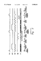
During the performance of a reading operation, it may become necessary to perform a page copy operation by copying data read from a first page of memory cells at a first address to a second page of memory cells at a second different address. As illustrated by FIG. 1, a conventional page copy operation typically includes the steps of reading data from a first page of memory cells 101 in an array 100 to a page buffer 300 and then to a storage device 400 external to the page buffer 300. Next, the data in the storage device 400 is returned to the page buffer 300 and then reprogrammed into the second page of memory cells 102 using conventional programming operations. The operations illustrated by FIG. 1 are more fully described by FIG. 2 which illustrates the timing of signals required to perform a conventional page copy operation. As will be understood by those skilled in the art, the signal CLE represents the command latch enable signal, the signal ALE represents the address latch enable signal, the signal WE represents the write enable signal and the signal RE represents the read enable signal. Referring now to FIG. 2, after applying a read command "00h" through an input/output (I/O) terminal during interval T1, addresses of three cycles are provided during interval T2 so that the memory device 100 outputs as a batch the data stored in all the memory cells of the first page 101 (designated by the addresses) through the bit lines. The output data is then sensed and temporarily retained by the page buffer 300 during interval T3. The read enable signal RE is then toggled to commence serial transfer of the retained data from the buffer 300 to the external storage device 400 during interval T4. A data loading command "80h" is then input and addresses of three cycles are applied during interval T5. The data stored in the storage device 400 in then loaded into the page buffer 300 during interval T6. Finally, a page programming command "10h" is inputted during interval T7 so that all memory cells in the second page 102 can be programmed during interval T8. Unfortunately, the page copy operations illustrated by FIG. 1 require external storage 400 and typically require that such external storage be loaded serially from the page buffer 300 and downloaded serially to the page buffer 300, which can very time consuming.
To address the limitations associated with the memory device and page copy operations illustrated by FIG. 1, alternative page copy operations were developed. For example, FIG. 3 illustrates a second conventional method for performing page copy operations. According to this method, a first page 101 of data is read into a page buffer 300 where it is retained in an inverted format. The retained data is then stored back into the memory 100 at an address of a second page 102. However, these page copy operations are limited because the copy of the original data from the first page is not stored as a "true" copy but is stored as an inverted copy. Accordingly, during subsequent read operations, it is possible for data errors to occur if the inverted copy is treated as a true copy.
Thus, notwithstanding the above described memory devices and methods for performing page copy operations, there continues to be a need for improved memory devices and methods for performing page copy operations which do not require external memory, serial loading or downloading operations and are not subject to the risk of data errors when true copies of data are not stored during page copy operations.
SUMMARY OF THE INVENTION
It is therefore an object of the present invention to provide improved integrated circuit memory devices, and methods of operating same.
It is another object of the present invention to provide integrated circuit memory devices which are capable of efficiently performing page copy operations, and methods of operating same.
It is still another object of the present invention to provide integrated circuit memory devices which have reduced susceptibility to errors when reading data stored during page copy operations, and methods of operating same.
These and other objects, features and advantages of the present invention are provided by integrated circuit memory devices which contain an array of memory cells and a plurality of flag cells coupled thereto which retain a flag to indicate whether a respective page of memory cells contains data copied in an inverted format from another page of memory cells. According to a preferred embodiment of the present invention, the memory cells and flag cells comprise EEPROM cells and each page of memory cells shares a word line with a respective flag cell. The flag may constitute a logic 1 (or logic 0) signal stored in the flag EEPROM cell to indicate whether the data in the corresponding page of memory is a true or an inverted copy of a page of data copied from another page at a different address. The preferred embodiment also comprises a page buffer to retain data read from a page of memory and read from a corresponding flag cell, and an exclusive OR gate (or NOR gate) for inverting the data outputted by the page buffer if the flag has been set and passing the outputted data unchanged if the flag has not been set.
Methods are also preferably provided for operating an integrated circuit memory device by reading data from a first page of memory cells into a page buffer which retains the read data in an inverted format and then copying the read data (in inverted format) from the page buffer into a second page of memory cells. In addition to these steps, a step is also performed to set a flag indicating that the data copied from the first page of memory cells into the second page of memory cells was read by the page buffer. The data in the second page of memory can then be transmitted to external the memory device by reading data from the second page of memory cells into the page buffer and then outputting the data from the page buffer and inverting the data if the flag has been set by transmitting the data through an exclusive gate having an input responsive to the value of the flag. Thus, the present invention eliminates the need to temporarily store page data to be copied in an external device and also eliminates the possibility that an error may occur when true copies of data are not stored during page copy operations.
BRIEF DESCRIPTION OF THE DRAWINGS
FIG. 1 illustrates operations for copying a page of memory from one address to another, according to a first conventional method.
FIG. 2 illustrates the timing of control signals used to perform the operations illustrated by FIG. 1.
FIG. 3 illustrates operations for copying a page of memory from one address to another, according to a second conventional method.
FIG. 4 illustrates a block diagram of an integrated circuit memory device according to one embodiment of the present invention.
FIG. 5 illustrates an electrical schematic of an exemplary page buffer from the memory device of FIG. 4.
FIG. 6 illustrates the timing of control signals used by the page buffer of FIG. 5 to perform a page read operation, according to the present invention.
FIG. 7 illustrates the timing of control signals used by the page buffer of FIG. 5 to program a page of memory, according to the present invention.
FIG. 8 illustrates operations for copying a first page of memory to a second page of memory, according to the present invention.
FIG. 9 illustrates operations for copying the second page of memory illustrated in FIG. 8 to a third page of memory, according to the present invention.
FIG. 10 illustrates operations for downloading the first page of memory illustrated in FIG. 8 to an input/output terminal, according to the present invention.
FIG. 11 illustrates operations for downloading the second page of memory illustrated in FIG. 8 to an input/output terminal, according to the present invention.
FIG. 12 illustrates the timing of control signals used by the memory device of FIG. 4 to program a page of memory.
FIG. 13 illustrates the timing of control signals used by the memory device of FIG. 4 to copy a page of memory.
DESCRIPTION OF PREFERRED EMBODIMENTS
The present invention will now be described more fully hereinafter with reference to the accompanying drawings, in which preferred embodiments of the invention are shown. This invention may, however, be embodied in different forms and should not be construed as limited to the embodiments set forth herein. Rather, these embodiments are provided so that this disclosure will be thorough and complete, and will fully convey the scope of the invention to those skilled in the art. Like numbers refer to like elements throughout.
Referring now to FIG. 4, a preferred integrated circuit memory device comprises a two-dimensional array of memory cells 100 arranged as a plurality of pages of memory cells electrically coupled to a respective plurality of word lines and a plurality of columns of memory cells electrically coupled to a respective plurality of bit lines. Such an array of memory cells 100 may include an array of NAND strings of EEPROM cells, as more fully described in commonly assigned U.S. Pat. No. 5,546,341 to Suh et al. entitled Nonvolatile Semiconductor Memory, the disclosure of which is hereby incorporated herein by reference. In addition to the array of memory cells 100, a plurality of flag cells 200 are also provided to retain flags (e.g., logic 1 values) to indicate whether respective pages of memory cells contain data copied in an inverted format from other pages of memory cells. The plurality of flag cells 200 may be arranged as a linear array of EEPROM cells so that each page of memory cells and its respective flag cell, share a respective word line.
The preferred memory device also comprises a page buffer 300 to retain data read from a page of memory cells and a respective flag cell. Here, the page buffer 300 may also comprise a column selection circuit so that the retained data from the page of memory cells can be outputted in serial format to a data inverter 500 such as a two-input exclusive OR (XOR) gate. The output of the data inverter 500 is then forwarded to an output buffer 600 and then ultimately to an input/output (I/O) terminal. An exemplary page buffer 500 is illustrated by FIG. 5 which is described more fully hereinbelow, however other latch and latch-free page buffers may also be used including those disclosed in U.S. Pat. No. 5,761,132, commonly assigned to the present assignee, the disclosure of which is hereby incorporated herein by reference. Referring still to FIG. 4, the output of the data inverter 500 is a function of the page data serially input at a first input and the value (i.e., logic 1 or 0) of the flag data which is input and held at a second input of the data inverter 500 while the page data is being serially output from the page buffer 300. For example, if the value of the flag data is a logic 1 value, which indicates that the flag has been set and the retained page data is an inverted copy of data from another page, the output of the data inverter 500 will represent an inverted version of the serial page data provided by the page buffer 300 and thus a "true" copy of the data copied from the original page. These operations are described more fully hereinbelow with respect to FIGS. 10-11.
Referring now to FIG. 5, an exemplary single-bit page buffer 300 is illustrated as being coupled in series through a bit line isolation transistor 302 (e.g., NMOS) to a bit line BL of a respective string of memory cells 301, such as a NAND string of EEPROM cells in the memory cell array 100. As will be understood by those skilled in the art, such single bit page buffers 300 are replicated for each respective string of memory cells in the array 100 to form a multibit page buffer. As illustrated, the page buffer 300 comprises an NMOS isolation transistor 304, an NMOS sense node discharge transistor 303, a PMOS bit line precharge transistor 307 which is tied to a logic 1 reference potential (e.g., Vcc), a data latch 310 comprising antiparallel-connected inverters (305, 306), an output inverter 311, an NMOS sense transistor 308 and an NMOS latch transistor 309.
Referring now to FIG. 6, a method of reading data from a predetermined memory cell in a selected string 301 into a page buffer 300 will now be described. As illustrated during time interval T11, the sense node SO and latch output node PB are reset to a logic 0 potential (e.g., GND) by simultaneously turning on the NMOS isolation transistor 304 and the NMOS sense node discharge transistor 303 by applying a logic 1 potential to signal lines DCB and SBL. Then, during time interval T22, the isolation transistor and sense node discharge transistor 304 and 303 are turned-off to isolate the latch output node PB and allow the sense node and bit line BL to be precharged to a logic 1 potential. The sense node SO and bit line BL are precharged by turning on the PMOS bit line precharge transistor 307 and turning on the bit line isolation transistor 302. These transistors are turned on by switching signal line Vref from 1→0 (e.g., 2 Volts→GND) and switching signal line BLSHF from 0→1 at the commencement of time interval T22. Once the bit line BL has been precharged to a logic 1 potential during time interval T22, Vref is switched back to a logic 1 potential (e.g., 1.7 Volts) to almost completely turn off the bit line precharge transistor 307 and allow the data in the selected memory cell of the selected string 301 to be sensed.
As will be understood by those skilled in the art, if the selected memory cell is an EEPROM cell which has been programmed to retain a logic 0 value, the high level of the threshold voltage of the selected memory cell will prevent the bit line BL from being discharged during a data sense operation. Thus, if the selected memory cell has been programmed, the sense node SO will remain at a logic 1 potential and hold the sense transistor 308 in the "on" state. The data on the sense node SO can then be latched during time interval T33 by switching φLatch from 0→1 to turn on the NMOS latch transistor 309. When this occurs, the input to the latch 310 will be pulled to a logic 0 potential and the latch output node PB will be clamped at a logic 1 potential. Thus, if the selected memory cell is programmed to retain a logic 0 value, the latch output node PB will be held at an inverted logic 1 value. However, if the selected memory cell is not programmed, the bit line BL will conduct current and the sense node SO will drop to a logic 0 potential to turn off the sense transistor 308 and hold the latch output at an inverted logic 0 value.
Accordingly, a reading operation causes the latch 310 to retain an inverted version of the data in the selected memory cell at the latch output node PB. If a page copy operation is performed by loading this and other inverted bits of the original page data back (from the latch output node PB) into new memory cells at a new page, an inverted copy of the original page data will become stored at the new page.
These operations for loading an inverted copy of a page of memory cells from the page buffer 300 back into a page of memory at a different address are more fully illustrated by FIG. 7. For example, during the time interval T21, the bit line BL is reset to logic 0 by turning on the sense node discharge transistor 303 (by switching DCB from 0→1) and turning or holding the bit line isolation transistor 302 on. Then, during time interval T31, the inverted data retained at the latch output node PB of the buffer latch 310 is passed back to the bit line BL by turning on the isolation transistor (by switching SBL from 0→1). Then, during time interval T41, the inverted copy of the original page data is programmed into a new page of memory.
The operations described above with respect to FIGS. 6-7 are also illustrated by FIGS. 8-9. For example, FIG. 8 illustrates the steps of reading data from a first page of memory 101 (in a memory cell array 100) into a page buffer 300 and then copying the read data in inverted format back into a second page of memory 102 and setting/toggling a respective flag bit (in a plurality of flag cells 200) to a logic 1 value to indicate that the data in the second page of memory 102 is an inverted copy of data from another page of memory (i.e., first page 101). Similarly, FIG. 9 illustrates the steps of reading data from the second page of memory 102 into the page buffer 300 and then copying the read data in inverted format back into a third page of memory 103 and toggling the flag bit from 1-0 to indicate that the data in the third page is now a true copy of data from another page (e.g., the first page 101) of memory.
Referring now to FIGS. 10-11, the operations for downloading pages of data to an input/output (I/O) terminal will now be described. In FIG. 10, the data from the first page of memory 101 is downloaded into the page buffer 300 along with the corresponding flag bit. The data in the page buffer 300 is then serially output to the data inverter 500. The data inverter 500 checks the flag bit and inverts the serial data if the flag bit is a logic 1 value but not if the flag bit is a logic 0 value. The illustrated data inverter 500 is a two-input exclusive OR (XOR) gate having an output coupled to an output buffer 600. Alternatively, in FIG. 11, the data from the second page of memory 102 is downloaded into the page buffer 300 along with the corresponding flag bit. The data in the page buffer 300 (i.e., 01100110) is then serially output to the data inverter 500 which checks the flag bit and inverts the serial data because the flag bit is a logic 1 value. Thus, the data outputted by the page buffer 600 is a true copy of the first page of memory (i.e., 10011001) from which the second page of memory was copied.
Referring now to FIG. 12, operations for programming memory with data serially recieved from an input/output (I/O) terminal will now be described. In particular, as illustrated by FIG. 12, the timing pulses inputted to perform a normal page programming operation are a command latch enable signal CLE, an address latch enable signal ALE, a write enable signal WE, and a read enable signal RE. When a data loading command "80h" is applied via the I/O terminal during interval T300, and addresses of three cycles are applied during interval T310, then 256 bytes of data, for example, are sequentially inputted to the page buffer 300 during interval T320. Finally, a page programming command "10h" is inputted during interval T330, and then the page programming operation is accomplished during interval T340. This is achieved by toggling the write enable signal WE with the command latch enable signal CLE at a logic 1 state, to cause the input data to be recognized by the memory as loading command.
In addition, the memory recognizes the address of the data inputted through the I/O terminal in the interval during which the address latch enable signal ALE is "high". The data inputted through the I/O terminal (by toggling the write enable signal WE) is identified as the input data for programming when the command latch enable and address latch enable signals ALE and CLE are all "low". Further, if the command latch enable and address latch enable signals CLE and ALE are all "low", and the read enable signal RE also "low", the data is internally inputted through the I/O terminal. For example, if one page contains 256 bytes, and if the data loading command "80h" is inputted and then the addresses of three cycles are applied, the 256 bytes of data are sequentially inputted. Finally, upon receipt of the page programming command "10", all the memory cells of a selected page are programmed. In this case, the flag cell attached to the selected page is programmed with "0" to indicate that the data is not in an inverted format.
The operations for performing a page copy will now be described with respect to FIG. 13. Here, the command latch enable signal CLE, the address latch enable signal ALE, the write enable signal WE, and the read enable signal RE are provided as control signals. If the read command "00h" is applied during interval T400, and the addresses of three cycles are applied during interval T410, the data in a page of memory is sensed during interval T420 and temporarily stored in the page buffer. The addresses of three cycles for identifying the address of the target page are applied after applying the page copy programming command "15h" in interval T430. The data stored in the page buffer is then programmed directly into the memory cells of the target page without being externally outputted. Here, the flag cell attached to the target page is programmed with a flag (i.e., logic 1). Then, when reading the data in the copied page, the value of the flag cell attached to the page causes the data inverter 500 to invert the logical state of the copied data to the logical state of the data so as to finally produce the original data as a serial string to the output buffer 600.
In the drawings and specification, there have been disclosed typical preferred embodiments of the invention and, although specific terms are employed, they are used in a generic and descriptive sense only and not for purposes of limitation, the scope of the invention being set forth in the following claims.

Claims (3)

That which is claimed is:
1. An integrated circuit memory device, comprising:
an array of memory cells arranged as a plurality of pages of memory cells electrically coupled to a respective plurality of word lines and a plurality of columns of memory cells electrically coupled to a respective plurality of bit lines;
a plurality of flag cells, each of said plurality of flag cells coupled to a respective one of the plurality of pages of memory cells by a respective word line and retaining a flag which indicates whether the respective one of the plurality of pages of memory cells contains data copied in an inverted format from another one of the plurality of pages of memory cells;
a page buffer, coupled to said array of memory cells and said plurality of flag cells, to retain data read from a page of memory cells and a respective flag cell; and
a data inverter, coupled to an output of said page buffer, to output an inverted copy of the read data if the respective flag cell contains a flag and pass the read data unchanged if the respective flag cell does not contain a flag;
wherein each of the plurality of pages of memory cells shares a word line with a respective flag cell in said plurality of flag cells.
2. The integrated circuit memory device of claim 1, wherein said array of memory cells and said plurality of flag cells comprise EEPROM cells.
3. The integrated circuit memory device of claim 1, wherein said data inverter comprises an exclusive OR gate.
US08/744,437 1995-11-10 1996-11-08 Integrated circuit memory devices having page flag cells which indicate the true or non-true state of page data therein and methods of operating the same Expired - Fee Related US5996041A (en)

Applications Claiming Priority (2)

Application Number Priority Date Filing Date Title
KR95-40639 1995-11-10
KR1019950040639A KR0172366B1 (en) 1995-11-10 1995-11-10 Non-volatile semiconductor memory device

Publications (1)

Publication Number Publication Date
US5996041A true US5996041A (en) 1999-11-30

Family

ID=19433644

Family Applications (1)

Application Number Title Priority Date Filing Date
US08/744,437 Expired - Fee Related US5996041A (en) 1995-11-10 1996-11-08 Integrated circuit memory devices having page flag cells which indicate the true or non-true state of page data therein and methods of operating the same

Country Status (6)

Country Link
US (1) US5996041A (en)
JP (1) JP3647996B2 (en)
KR (1) KR0172366B1 (en)
DE (1) DE19646216C2 (en)
IT (1) IT1286092B1 (en)
TW (1) TW347537B (en)

Cited By (35)

* Cited by examiner, † Cited by third party
Publication number Priority date Publication date Assignee Title
WO2001095334A2 (en) * 2000-06-07 2001-12-13 Advanced Micro Devices, Inc. Power saving scheme for burst mode implementation during reading of data from a memory device
WO2002015192A1 (en) * 2000-08-17 2002-02-21 Xemics Sa Control module comprising a read-only memory with reduced power consumption
US20030076719A1 (en) * 2001-10-24 2003-04-24 Samsung Electronics Co., Ltd. Non-volatile semiconductor memory device with cache function and program, read, and page copy-back operations thereof
US6671204B2 (en) 2001-07-23 2003-12-30 Samsung Electronics Co., Ltd. Nonvolatile memory device with page buffer having dual registers and methods of using the same
US20040090849A1 (en) * 2001-07-17 2004-05-13 Kabushiki Kaisha Toshiba Semiconductor storage device having page copying function
US20040202034A1 (en) * 2003-04-03 2004-10-14 Jin-Yub Lee Nonvolatile memory with error correction for page copy operation and method thereof
US6813184B2 (en) 2002-01-12 2004-11-02 Samsung Electronics Co., Ltd. NAND flash memory and method of erasing, programming, and copy-back programming thereof
EP1517333A1 (en) * 2003-08-07 2005-03-23 Giesecke & Devrient GmbH Flag for memory with asymmetry concerning programming and erasure
US20050232011A1 (en) * 2001-07-23 2005-10-20 Samsung Electronics Co., Ltd. Memory devices with page buffer having dual registers and metod of using the same
US20060120172A1 (en) * 2004-10-28 2006-06-08 Sung-Soo Lee Page-buffer and non-volatile semiconductor memory including page buffer
US20060146607A1 (en) * 2002-02-06 2006-07-06 Kabushiki Kaisha Toshiba Non-volatile semiconductor memory device
US20060291305A1 (en) * 2005-05-30 2006-12-28 Norikatsu Suzuki Semiconductor device and program data redundancy method therefor
US20070096780A1 (en) * 2005-10-28 2007-05-03 Analog Devices, Inc. Output stage interface circuit for outputting digital data onto a data bus
US20070133291A1 (en) * 2005-12-14 2007-06-14 Kabushiki Kaisha Toshiba Nonvolatile semiconductor memory device
US20070171711A1 (en) * 2006-01-24 2007-07-26 Dong-Ku Kang Non-volatile memory device and method of operation therefor
US20080065812A1 (en) * 2006-09-08 2008-03-13 Yan Li Pseudo random and command driven bit compensation for the cycling effects in flash memory
WO2008031074A1 (en) * 2006-09-08 2008-03-13 Sandisk Corporation Pseudo random and command driven bit compensation for the cycling effects in flash memory and methods therefor
US20080065813A1 (en) * 2006-09-08 2008-03-13 Yan Li Methods in a pseudo random and command driven bit compensation for the cycling effects in flash memory
US20080068886A1 (en) * 2006-08-28 2008-03-20 Samsung Electronics Co., Ltd. Flash Memory Devices Having Multi-Page Copyback Functionality and Related Block Replacement Methods
US20090067244A1 (en) * 2007-09-07 2009-03-12 Yan Li Nonvolatile memory and method for on-chip pseudo-randomization of data within a page and between pages
US20090103366A1 (en) * 2007-10-17 2009-04-23 Samsung Electronics Co., Ltd. Non-volatile memory device
US20100070821A1 (en) * 2008-09-12 2010-03-18 Kwan-Ho Kim Method and apparatus for detecting free page and a method and apparatus for decoding error correction code using the method and apparatus for detecting free page
US20100332898A1 (en) * 2009-06-29 2010-12-30 Hynix Semiconductor Inc. Nonvolatile memory device and copyback program method thereof
US7958430B1 (en) 2005-06-20 2011-06-07 Cypress Semiconductor Corporation Flash memory device and method
US20110242890A1 (en) * 2002-11-29 2011-10-06 Noboru Shibata Semiconductor memory device for storing multivalued data
USRE42976E1 (en) * 2002-10-29 2011-11-29 Hynix Semiconductor, Inc. Semiconductor memory device with reduced data access time
US20120314496A1 (en) * 2010-02-08 2012-12-13 Donghyuk Chae Nonvolatile memory devices having improved read reliability
US20130114344A1 (en) * 2011-11-09 2013-05-09 Manabu Sakai Erratic program detection for non-volatile storage
US20130128663A1 (en) * 2011-11-21 2013-05-23 Samsung Electronics Co., Ltd. Non-volatile memory device and method for programming non-volatile memory device
US8843693B2 (en) 2011-05-17 2014-09-23 SanDisk Technologies, Inc. Non-volatile memory and method with improved data scrambling
US20150363313A1 (en) * 2010-11-09 2015-12-17 Micron Technology, Inc. Sense operation flags in a memory device
USRE46014E1 (en) 2011-11-09 2016-05-24 Sandisk Technologies Inc. Defective word line detection
US9965205B2 (en) * 2014-12-18 2018-05-08 SK Hynix Inc. Data storage device performing a scramble operation and operating method thereof
US10108370B2 (en) 2016-05-10 2018-10-23 Samsung Electronics Co., Ltd. Methods of reading nonvolatile memory devices
US11017848B2 (en) * 2019-10-22 2021-05-25 Samsung Electronics Co., Ltd. Static random-access memory (SRAM) system with delay tuning and control and a method thereof

Families Citing this family (10)

* Cited by examiner, † Cited by third party
Publication number Priority date Publication date Assignee Title
JP2001006379A (en) * 1999-06-16 2001-01-12 Fujitsu Ltd Flash memory having copying and transfer functions
JP4563715B2 (en) * 2003-04-29 2010-10-13 三星電子株式会社 Flash memory device having partial copyback operation mode
KR100626393B1 (en) * 2005-04-07 2006-09-20 삼성전자주식회사 Non-volatile memory device and multi-page copyback method thereof
JP4955990B2 (en) * 2005-12-14 2012-06-20 株式会社東芝 Nonvolatile semiconductor memory device
JP4984666B2 (en) * 2006-06-12 2012-07-25 ソニー株式会社 Non-volatile memory
KR100758300B1 (en) * 2006-07-26 2007-09-12 삼성전자주식회사 Flash memory device and program method thereof
KR100782329B1 (en) 2006-10-02 2007-12-06 삼성전자주식회사 Nonvolatile memory device having a separately arranged flag cell array in memory cell array and method of operating the same
KR100826654B1 (en) * 2007-04-24 2008-05-06 주식회사 하이닉스반도체 Method of operating flash memory device and control circuit for the operating method
JP2010027163A (en) * 2008-07-22 2010-02-04 Toshiba Corp Semiconductor memory controller, semiconductor memory system, and recording/reproducing method for the semiconductor memory system
JP6271460B2 (en) * 2015-03-02 2018-01-31 東芝メモリ株式会社 Semiconductor memory device

Citations (10)

* Cited by examiner, † Cited by third party
Publication number Priority date Publication date Assignee Title
US5172339A (en) * 1989-08-29 1992-12-15 Mitsubishi Denki Kabushiki Kaisha Semiconductor memory device having error checking and correcting circuit and operating method therefor
US5293212A (en) * 1991-02-08 1994-03-08 Mitsubishi Denki Kabushiki Kaisha Non-volatile semiconductor memory device allowing erase of storage data of an arbitrary memory cell and method of erasing data in non-volatile semiconductor memory device
US5299162A (en) * 1992-02-21 1994-03-29 Samsung Electronics Co., Ltd. Nonvolatile semiconductor memory device and an optimizing programming method thereof
US5347490A (en) * 1990-06-15 1994-09-13 Mitsubishi Denki Kabushiki Kaisha Nonvolatile semiconductor memory device
US5465235A (en) * 1993-09-02 1995-11-07 Kabushiki Kaisha Toshiba Non-volatile memory device with a sense amplifier capable of copying back
US5625590A (en) * 1994-12-19 1997-04-29 Samsung Electronics Co., Ltd. Nonvolatile semiconductor memory
US5671178A (en) * 1995-02-04 1997-09-23 Samsung Electronics Co., Ltd. Erase verifying circuit for a nonvolatile semiconductor memory with column redundancy
US5677873A (en) * 1995-09-19 1997-10-14 Samsung Electronics Co., Ltd. Methods of programming flash EEPROM integrated circuit memory devices to prevent inadvertent programming of nondesignated NAND memory cells therein
US5682345A (en) * 1995-07-28 1997-10-28 Micron Quantum Devices, Inc. Non-volatile data storage unit method of controlling same
US5696717A (en) * 1995-10-16 1997-12-09 Samsung Electronics Co., Ltd. Nonvolatile integrated circuit memory devices having adjustable erase/program threshold voltage verification capability

Family Cites Families (1)

* Cited by examiner, † Cited by third party
Publication number Priority date Publication date Assignee Title
JPH06267283A (en) * 1993-03-16 1994-09-22 Mitsubishi Electric Corp Read-only memory writable data and method for writing/ reading data

Patent Citations (10)

* Cited by examiner, † Cited by third party
Publication number Priority date Publication date Assignee Title
US5172339A (en) * 1989-08-29 1992-12-15 Mitsubishi Denki Kabushiki Kaisha Semiconductor memory device having error checking and correcting circuit and operating method therefor
US5347490A (en) * 1990-06-15 1994-09-13 Mitsubishi Denki Kabushiki Kaisha Nonvolatile semiconductor memory device
US5293212A (en) * 1991-02-08 1994-03-08 Mitsubishi Denki Kabushiki Kaisha Non-volatile semiconductor memory device allowing erase of storage data of an arbitrary memory cell and method of erasing data in non-volatile semiconductor memory device
US5299162A (en) * 1992-02-21 1994-03-29 Samsung Electronics Co., Ltd. Nonvolatile semiconductor memory device and an optimizing programming method thereof
US5465235A (en) * 1993-09-02 1995-11-07 Kabushiki Kaisha Toshiba Non-volatile memory device with a sense amplifier capable of copying back
US5625590A (en) * 1994-12-19 1997-04-29 Samsung Electronics Co., Ltd. Nonvolatile semiconductor memory
US5671178A (en) * 1995-02-04 1997-09-23 Samsung Electronics Co., Ltd. Erase verifying circuit for a nonvolatile semiconductor memory with column redundancy
US5682345A (en) * 1995-07-28 1997-10-28 Micron Quantum Devices, Inc. Non-volatile data storage unit method of controlling same
US5677873A (en) * 1995-09-19 1997-10-14 Samsung Electronics Co., Ltd. Methods of programming flash EEPROM integrated circuit memory devices to prevent inadvertent programming of nondesignated NAND memory cells therein
US5696717A (en) * 1995-10-16 1997-12-09 Samsung Electronics Co., Ltd. Nonvolatile integrated circuit memory devices having adjustable erase/program threshold voltage verification capability

Non-Patent Citations (4)

* Cited by examiner, † Cited by third party
Title
"Error Check And Correction For Soft Error Of Dynamic Random-Access"; Mar. 1989; vol. 31, No. 10; pp. 58-60.
Error Check And Correction For Soft Error Of Dynamic Random Access ; Mar. 1989; vol. 31, No. 10; pp. 58 60. *
H.S. Anand, "High Performance, Single bit Error Correction" Nov. 1983; vol. 26; pp. 2958-2960.
H.S. Anand, High Performance, Single bit Error Correction Nov. 1983; vol. 26; pp. 2958 2960. *

Cited By (106)

* Cited by examiner, † Cited by third party
Publication number Priority date Publication date Assignee Title
WO2001095334A3 (en) * 2000-06-07 2002-06-06 Advanced Micro Devices Inc Power saving scheme for burst mode implementation during reading of data from a memory device
US6463003B2 (en) 2000-06-07 2002-10-08 Advanced Micro Devices, Inc. Power saving scheme for burst mode implementation during reading of data from a memory device
WO2001095334A2 (en) * 2000-06-07 2001-12-13 Advanced Micro Devices, Inc. Power saving scheme for burst mode implementation during reading of data from a memory device
US7107387B2 (en) 2000-08-17 2006-09-12 Semtech Neuchatel Sa Control module comprising a ROM with reduced electrical consumption
WO2002015192A1 (en) * 2000-08-17 2002-02-21 Xemics Sa Control module comprising a read-only memory with reduced power consumption
US20030156480A1 (en) * 2000-08-17 2003-08-21 Philippe Mosch Control module comprising a ROM with reduced electrical consumption
US20040090849A1 (en) * 2001-07-17 2004-05-13 Kabushiki Kaisha Toshiba Semiconductor storage device having page copying function
US20080181005A1 (en) * 2001-07-17 2008-07-31 Koichi Kawai Semiconductor storage device having page copying function
US7082054B2 (en) 2001-07-17 2006-07-25 Kabushiki Kaisha Toshiba Semiconductor storage device having page copying function
US7315473B2 (en) 2001-07-17 2008-01-01 Kabushiki Kaisha Toshiba Semiconductor storage device having page copying function
US20070047360A1 (en) * 2001-07-17 2007-03-01 Kabushiki Kaisha Toshiba Semiconductor storage device having page copying function
US7180778B2 (en) 2001-07-17 2007-02-20 Kabushiki Kaisha Toshiba Semiconductor storage device having page copying function
US7130217B2 (en) 2001-07-17 2006-10-31 Kabushiki Kaisha Toshiba Semiconductor storage device having page copying function
US20060002214A1 (en) * 2001-07-17 2006-01-05 Koichi Kawai Semiconductor storage device having page copying function
US20060002213A1 (en) * 2001-07-17 2006-01-05 Koichi Kawai Semiconductor storage device having page copying function
US7596027B2 (en) 2001-07-17 2009-09-29 Kabushiki Kaisha Toshiba Semiconductor storage device having page copying function
US7016228B2 (en) 2001-07-17 2006-03-21 Kabushiki Kaisha Toshiba Semiconductor storage device having page copying function
US20060164897A1 (en) * 2001-07-17 2006-07-27 Koichi Kawai Semiconductor storage device having page copying function
US7602644B2 (en) 2001-07-23 2009-10-13 Samsung Electronics Co., Ltd. Memory devices with page buffer having dual registers and method of using the same
US7787300B2 (en) 2001-07-23 2010-08-31 Samsung Electronics Co., Ltd. Memory devices with page buffer having dual registers and method of using the same
US6671204B2 (en) 2001-07-23 2003-12-30 Samsung Electronics Co., Ltd. Nonvolatile memory device with page buffer having dual registers and methods of using the same
US7042770B2 (en) 2001-07-23 2006-05-09 Samsung Electronics Co., Ltd. Memory devices with page buffer having dual registers and method of using the same
US20060083063A1 (en) * 2001-07-23 2006-04-20 Samsung Electronics Co., Ltd. Memory devices with page buffer having dual registers and method of using the same
US6996014B2 (en) 2001-07-23 2006-02-07 Samsung Electronics Co., Ltd. Memory devices with page buffer having dual registers and method of using the same
US20050232011A1 (en) * 2001-07-23 2005-10-20 Samsung Electronics Co., Ltd. Memory devices with page buffer having dual registers and metod of using the same
US7227785B2 (en) 2001-07-23 2007-06-05 Samsung Electronics Co., Ltd. Memory devices with page buffer having dual registers and method of using the same
US20030076719A1 (en) * 2001-10-24 2003-04-24 Samsung Electronics Co., Ltd. Non-volatile semiconductor memory device with cache function and program, read, and page copy-back operations thereof
US6717857B2 (en) 2001-10-24 2004-04-06 Samsung Electronics Co., Ltd. Non-volatile semiconductor memory device with cache function and program, read, and page copy-back operations thereof
US6813184B2 (en) 2002-01-12 2004-11-02 Samsung Electronics Co., Ltd. NAND flash memory and method of erasing, programming, and copy-back programming thereof
US7330372B2 (en) 2002-02-06 2008-02-12 Kabushiki Kaisha Toshiba Non-volatile semiconductor memory device
US20060146607A1 (en) * 2002-02-06 2006-07-06 Kabushiki Kaisha Toshiba Non-volatile semiconductor memory device
US7586785B2 (en) 2002-02-06 2009-09-08 Kabushiki Kaisha Toshiba Non-volatile semiconductor memory device
US20080175052A1 (en) * 2002-02-06 2008-07-24 Kabushiki Kaisha Toshiba Non-Volatile Semiconductor Memory Device
USRE42976E1 (en) * 2002-10-29 2011-11-29 Hynix Semiconductor, Inc. Semiconductor memory device with reduced data access time
US20160012906A1 (en) * 2002-11-29 2016-01-14 Kabushiki Kaisha Toshiba Semiconductor memory device for storing multivalued data
US20170053706A1 (en) * 2002-11-29 2017-02-23 Kabushiki Kaisha Toshiba Semiconductor memory device for storing multivalued data
US8947930B2 (en) 2002-11-29 2015-02-03 Kabushiki Kaisha Toshiba Semiconductor memory device for storing multivalued data
US11264108B2 (en) 2002-11-29 2022-03-01 Kioxia Corporation Semiconductor memory device for storing multivalued data
US10867686B2 (en) 2002-11-29 2020-12-15 Toshiba Memory Corporation Semiconductor memory device for storing multivalued data
US10636502B2 (en) 2002-11-29 2020-04-28 Toshiba Memory Corporation Semiconductor memory device for storing multivalued data
US9183936B2 (en) 2002-11-29 2015-11-10 Kabushiki Kaisha Toshiba Semiconductor memory device for storing multivalued data
US8310871B2 (en) * 2002-11-29 2012-11-13 Kabushiki Kaisha Toshiba Semiconductor memory device for storing multivalued data
US9460804B2 (en) * 2002-11-29 2016-10-04 Kabushiki Kaisha Toshiba Semiconductor memory device for storing multivalued data
US8743607B2 (en) 2002-11-29 2014-06-03 Kabushiki Kaisha Toshiba Semiconductor memory device for storing multivalued data
US8619468B2 (en) 2002-11-29 2013-12-31 Kabushiki Kaisha Toshiba Semiconductor memory device for storing multivalued data
US10418117B2 (en) 2002-11-29 2019-09-17 Toshiba Memory Corporation Semiconductor memory device for storing multivalued data
US20110242890A1 (en) * 2002-11-29 2011-10-06 Noboru Shibata Semiconductor memory device for storing multivalued data
US10109358B2 (en) 2002-11-29 2018-10-23 Toshiba Memory Corporation Semiconductor memory device for storing multivalued data
US9881681B2 (en) * 2002-11-29 2018-01-30 Toshiba Memory Corporation Semiconductor memory device for storing multivalued data
DE10344021B4 (en) * 2002-12-09 2008-01-17 Samsung Electronics Co., Ltd., Suwon Non-volatile memory device, programming device and programming method
US7296128B2 (en) * 2003-04-03 2007-11-13 Samsung Electronics Co., Ltd. Nonvolatile memory with error correction for page copy operation and method thereof
US20080163030A1 (en) * 2003-04-03 2008-07-03 Samsung Electronics Co., Ltd. Nonvolatile memory with error correction for page copy operation and method thereof
US20040202034A1 (en) * 2003-04-03 2004-10-14 Jin-Yub Lee Nonvolatile memory with error correction for page copy operation and method thereof
EP1517333A1 (en) * 2003-08-07 2005-03-23 Giesecke & Devrient GmbH Flag for memory with asymmetry concerning programming and erasure
US8493785B2 (en) 2004-10-28 2013-07-23 Samsung Electronics Co., Ltd. Page-buffer and non-volatile semiconductor memory including page buffer
US8174888B2 (en) * 2004-10-28 2012-05-08 Samsung Electronics Co., Ltd. Page-buffer and non-volatile semiconductor memory including page buffer
US20100202204A1 (en) * 2004-10-28 2010-08-12 Samsung Electronics Co., Ltd. Page-buffer and non-volatile semiconductor memory including page buffer
US7379333B2 (en) * 2004-10-28 2008-05-27 Samsung Electronics Co., Ltd. Page-buffer and non-volatile semiconductor memory including page buffer
US20060120172A1 (en) * 2004-10-28 2006-06-08 Sung-Soo Lee Page-buffer and non-volatile semiconductor memory including page buffer
US7739559B2 (en) 2005-05-30 2010-06-15 Spansion Llc Semiconductor device and program data redundancy method therefor
US20060291305A1 (en) * 2005-05-30 2006-12-28 Norikatsu Suzuki Semiconductor device and program data redundancy method therefor
US7958430B1 (en) 2005-06-20 2011-06-07 Cypress Semiconductor Corporation Flash memory device and method
US20070096780A1 (en) * 2005-10-28 2007-05-03 Analog Devices, Inc. Output stage interface circuit for outputting digital data onto a data bus
US7233179B2 (en) 2005-10-28 2007-06-19 Analog Devices, Inc. Output stage interface circuit for outputting digital data onto a data bus
US20070133291A1 (en) * 2005-12-14 2007-06-14 Kabushiki Kaisha Toshiba Nonvolatile semiconductor memory device
US7505318B2 (en) * 2005-12-14 2009-03-17 Kabushiki Kaisha Toshiba Nonvolatile semiconductor memory device
US20090296482A1 (en) * 2006-01-24 2009-12-03 Dong-Ku Kang Non-volatile memory device and method of operation therefor
US7589998B2 (en) * 2006-01-24 2009-09-15 Samsung Electronics Co., Ltd. Non-volatile memory device and method of operation therefor
US8050115B2 (en) 2006-01-24 2011-11-01 Samsung Electronics Co., Ltd. Non-volatile memory device and method of operation therefor
US20070171711A1 (en) * 2006-01-24 2007-07-26 Dong-Ku Kang Non-volatile memory device and method of operation therefor
US20080068886A1 (en) * 2006-08-28 2008-03-20 Samsung Electronics Co., Ltd. Flash Memory Devices Having Multi-Page Copyback Functionality and Related Block Replacement Methods
CN101221812B (en) * 2006-08-28 2012-04-18 三星电子株式会社 Flash memory device having multi-page copyback functionality and related block replacement method
US7684241B2 (en) 2006-08-28 2010-03-23 Samsung Electronics Co., Ltd. Flash memory devices having multi-page copyback functionality and related block replacement methods
US7734861B2 (en) * 2006-09-08 2010-06-08 Sandisk Corporation Pseudo random and command driven bit compensation for the cycling effects in flash memory
KR101615773B1 (en) 2006-09-08 2016-04-26 샌디스크 테크놀로지스, 인코포레이티드 Pseudo random and command driven bit compensation for the cycling effects in flash memory and methods therefor
US20080065812A1 (en) * 2006-09-08 2008-03-13 Yan Li Pseudo random and command driven bit compensation for the cycling effects in flash memory
WO2008031074A1 (en) * 2006-09-08 2008-03-13 Sandisk Corporation Pseudo random and command driven bit compensation for the cycling effects in flash memory and methods therefor
CN101512668B (en) * 2006-09-08 2013-12-11 桑迪士克科技公司 Pseudo random and command driven bit compensation for the cycling effects in flash memory and methods therefor
US7606966B2 (en) * 2006-09-08 2009-10-20 Sandisk Corporation Methods in a pseudo random and command driven bit compensation for the cycling effects in flash memory
US20080065813A1 (en) * 2006-09-08 2008-03-13 Yan Li Methods in a pseudo random and command driven bit compensation for the cycling effects in flash memory
US20090067244A1 (en) * 2007-09-07 2009-03-12 Yan Li Nonvolatile memory and method for on-chip pseudo-randomization of data within a page and between pages
WO2009035834A3 (en) * 2007-09-07 2009-05-22 Sandisk Corp Nonvolatile memory and method for on-chip pseudo-randomization of data within a page and between pages
KR101533965B1 (en) * 2007-09-07 2015-07-06 샌디스크 테크놀로지스, 인코포레이티드 Nonvolatile memory and method for on-chip pseudo-randomization of data within a page and between pages
US7885112B2 (en) 2007-09-07 2011-02-08 Sandisk Corporation Nonvolatile memory and method for on-chip pseudo-randomization of data within a page and between pages
US20090103366A1 (en) * 2007-10-17 2009-04-23 Samsung Electronics Co., Ltd. Non-volatile memory device
US7672167B2 (en) * 2007-10-17 2010-03-02 Samsung Electronics Co., Ltd. Non-volatile memory device
KR101497545B1 (en) * 2008-09-12 2015-03-03 삼성전자주식회사 Method and apparatus for detecting free page and error correction code decoding method and apparatus using the same
US20100070821A1 (en) * 2008-09-12 2010-03-18 Kwan-Ho Kim Method and apparatus for detecting free page and a method and apparatus for decoding error correction code using the method and apparatus for detecting free page
US8429485B2 (en) * 2008-09-12 2013-04-23 Samsung Electronics Co., Ltd. Method and apparatus for detecting free page and a method and apparatus for decoding error correction code using the method and apparatus for detecting free page
US20100332898A1 (en) * 2009-06-29 2010-12-30 Hynix Semiconductor Inc. Nonvolatile memory device and copyback program method thereof
US20120314496A1 (en) * 2010-02-08 2012-12-13 Donghyuk Chae Nonvolatile memory devices having improved read reliability
US9519582B2 (en) * 2010-11-09 2016-12-13 Micron Technology, Inc. Sense operation flags in a memory device
US20150363313A1 (en) * 2010-11-09 2015-12-17 Micron Technology, Inc. Sense operation flags in a memory device
US11029861B2 (en) 2010-11-09 2021-06-08 Micron Technology, Inc. Sense flags in a memory device
US10409506B2 (en) 2010-11-09 2019-09-10 Micron Technology, Inc. Sense flags in a memory device
US10126967B2 (en) 2010-11-09 2018-11-13 Micron Technology, Inc. Sense operation flags in a memory device
US8843693B2 (en) 2011-05-17 2014-09-23 SanDisk Technologies, Inc. Non-volatile memory and method with improved data scrambling
US8842476B2 (en) * 2011-11-09 2014-09-23 Sandisk Technologies Inc. Erratic program detection for non-volatile storage
USRE46014E1 (en) 2011-11-09 2016-05-24 Sandisk Technologies Inc. Defective word line detection
US20130114344A1 (en) * 2011-11-09 2013-05-09 Manabu Sakai Erratic program detection for non-volatile storage
US8705275B2 (en) * 2011-11-21 2014-04-22 Samsung Electronics Co., Ltd. Non-volatile memory device and method for programming non-volatile memory device
US20130128663A1 (en) * 2011-11-21 2013-05-23 Samsung Electronics Co., Ltd. Non-volatile memory device and method for programming non-volatile memory device
KR101799765B1 (en) 2011-11-21 2017-11-22 삼성전자주식회사 Method for programing non-volatile memory device
US9965205B2 (en) * 2014-12-18 2018-05-08 SK Hynix Inc. Data storage device performing a scramble operation and operating method thereof
US10108370B2 (en) 2016-05-10 2018-10-23 Samsung Electronics Co., Ltd. Methods of reading nonvolatile memory devices
US11017848B2 (en) * 2019-10-22 2021-05-25 Samsung Electronics Co., Ltd. Static random-access memory (SRAM) system with delay tuning and control and a method thereof

Also Published As

Publication number Publication date
KR970029868A (en) 1997-06-26
DE19646216C2 (en) 1999-09-09
JPH09180477A (en) 1997-07-11
ITMI962323A1 (en) 1998-05-08
IT1286092B1 (en) 1998-07-07
DE19646216A1 (en) 1997-05-15
TW347537B (en) 1998-12-11
ITMI962323A0 (en) 1996-11-08
KR0172366B1 (en) 1999-03-30
JP3647996B2 (en) 2005-05-18

Similar Documents

Publication Publication Date Title
US5996041A (en) Integrated circuit memory devices having page flag cells which indicate the true or non-true state of page data therein and methods of operating the same
US5768191A (en) Methods of programming multi-state integrated circuit memory devices
US6512702B1 (en) Non-volatile semiconductor memory device and data erase controlling method for use therein
US5768215A (en) Integrated circuit memory devices having interleaved read capability and methods of operating same
US6067248A (en) Nonvolatile semiconductor memory with single-bit and multi-bit modes of operation and method for performing programming and reading operations therein
KR0172441B1 (en) Programming method of non-volatile semiconductor memory
KR950000273B1 (en) Non-volatile semiconductor memory device and optimal write method
US6262926B1 (en) Nonvolatile semiconductor memory device
US5748529A (en) Integrated circuit memory devices having direct read capability
US5966326A (en) Nonvolatile semiconductor memory equipped with single bit and multi-bit cells
US7095657B2 (en) Nonvolatile semiconductor memory device capable of realizing optimized erasing operation in a memory array
CA2257740C (en) Method and apparatus of column redundancy for non-volatile analog and multilevel memory integrated circuits
US5327384A (en) Flash memory
JP4566369B2 (en) Nonvolatile semiconductor memory device
US5892715A (en) Non-volatile semiconductor memory device with variable source voltage
US5369609A (en) Floating gate memory array with latches having improved immunity to write disturbance, and with storage latches
EP0297540A2 (en) Memory cell of nonvolatile semiconductor memory device
KR100514415B1 (en) Page buffer for NAND flash memory
US6147910A (en) Parallel read and verify for floating gate memory device
KR960005370B1 (en) Method for erasing and verifying nonvolatile semiconductor memory device
US4805151A (en) Nonvolatile semiconductor memory device
US5761132A (en) Integrated circuit memory devices with latch-free page buffers therein for preventing read failures
US6876577B2 (en) Programming method of nonvolatile semiconductor memory device
WO1997005623A1 (en) Flash memory system having reduced disturb and method
US5949709A (en) Electrically programmable memory, method of programming and method of reading

Legal Events

Date Code Title Description
AS Assignment

Owner name: SANSUNG ELECTRONICS CO., LTD., KOREA, REPUBLIC OF

Free format text: ASSIGNMENT OF ASSIGNORS INTEREST;ASSIGNOR:KIM, JIN-KI;REEL/FRAME:008331/0703

Effective date: 19961120

FEPP Fee payment procedure

Free format text: PAYOR NUMBER ASSIGNED (ORIGINAL EVENT CODE: ASPN); ENTITY STATUS OF PATENT OWNER: LARGE ENTITY

FEPP Fee payment procedure

Free format text: PAYER NUMBER DE-ASSIGNED (ORIGINAL EVENT CODE: RMPN); ENTITY STATUS OF PATENT OWNER: LARGE ENTITY

Free format text: PAYOR NUMBER ASSIGNED (ORIGINAL EVENT CODE: ASPN); ENTITY STATUS OF PATENT OWNER: LARGE ENTITY

FPAY Fee payment

Year of fee payment: 4

FPAY Fee payment

Year of fee payment: 8

REMI Maintenance fee reminder mailed
LAPS Lapse for failure to pay maintenance fees
STCH Information on status: patent discontinuation

Free format text: PATENT EXPIRED DUE TO NONPAYMENT OF MAINTENANCE FEES UNDER 37 CFR 1.362

FP Lapsed due to failure to pay maintenance fee

Effective date: 20111130