US5999130A - Determination of radar threat location from an airborne vehicle - Google Patents
Determination of radar threat location from an airborne vehicle Download PDFInfo
- Publication number
- US5999130A US5999130A US09/057,018 US5701898A US5999130A US 5999130 A US5999130 A US 5999130A US 5701898 A US5701898 A US 5701898A US 5999130 A US5999130 A US 5999130A
- Authority
- US
- United States
- Prior art keywords
- sub
- probe signal
- coordinates
- location
- satisfy
- Prior art date
- Legal status (The legal status is an assumption and is not a legal conclusion. Google has not performed a legal analysis and makes no representation as to the accuracy of the status listed.)
- Expired - Fee Related
Links
Images


Classifications
-
- G—PHYSICS
- G01—MEASURING; TESTING
- G01S—RADIO DIRECTION-FINDING; RADIO NAVIGATION; DETERMINING DISTANCE OR VELOCITY BY USE OF RADIO WAVES; LOCATING OR PRESENCE-DETECTING BY USE OF THE REFLECTION OR RERADIATION OF RADIO WAVES; ANALOGOUS ARRANGEMENTS USING OTHER WAVES
- G01S5/00—Position-fixing by co-ordinating two or more direction or position line determinations; Position-fixing by co-ordinating two or more distance determinations
- G01S5/02—Position-fixing by co-ordinating two or more direction or position line determinations; Position-fixing by co-ordinating two or more distance determinations using radio waves
- G01S5/04—Position of source determined by a plurality of spaced direction-finders
-
- G—PHYSICS
- G01—MEASURING; TESTING
- G01S—RADIO DIRECTION-FINDING; RADIO NAVIGATION; DETERMINING DISTANCE OR VELOCITY BY USE OF RADIO WAVES; LOCATING OR PRESENCE-DETECTING BY USE OF THE REFLECTION OR RERADIATION OF RADIO WAVES; ANALOGOUS ARRANGEMENTS USING OTHER WAVES
- G01S7/00—Details of systems according to groups G01S13/00, G01S15/00, G01S17/00
- G01S7/02—Details of systems according to groups G01S13/00, G01S15/00, G01S17/00 of systems according to group G01S13/00
- G01S7/021—Auxiliary means for detecting or identifying radar signals or the like, e.g. radar jamming signals
Definitions
- This invention relates to determination of location, velocity and other attributes of an active threat radar site, using measurements made from an airborne vehicle.
- an airborne vehicle When operating in a hostile environment, an airborne vehicle often uses a radar electronic surveillance system (RESS) to determine the presence of (possibly unfriendly) probe signals from a threat radar system (TRS), which may be ground-based, water-based or air-based. If such a probe signal is identified, the RESS, at best, is able to determine the relative bearing of the TRS from the present airborne vehicle location. This relative bearing information is sufficient to alert the airborne vehicle occupants to presence of a radar interrogation threat but does not, by itself, allow determination of the present location and/or velocity of the TRS. Lacking additional information, the airborne vehicle can only determine the general direction of the source of the TRS probe signals.
- RESS radar electronic surveillance system
- the invention meets these needs by providing a hybrid method, using location information from two or more sources, that allows real time determination of location of, distance to, and/or velocity of, an active TRS facility.
- the airborne vehicle is provided with (1) signal direction finding means to quickly determine the direction of propagation of probe signals received at the vehicle, (2) a satellite-based or other location determination (LD) system, such as GPS or GLONASS or LEO, and (3) an appropriately programmed computer that uses this direction and location information to quickly determine, by triangulation or other appropriate computations, location and/or velocity coordinates for the TRS facility, which may be moving.
- LD location determination
- the approach requires determination of the probe signal direction and of the vehicle location at two or more probe signal receiver locations, which may be arbitrarily located relative to each other.
- the intersection of the first and second planes defines a source line; and the TRS facility is estimated to lie along this source line.
- FIG. 1 illustrates practice of the invention in one embodiment.
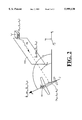
- FIG. 2 illustrates angle conventions used in the invention.
- FIG. 3 is a flow chart for practicing the invention.
- an aircraft 11 moves along a selected path P, and as this vehicle moves it receives probe signals PS transmitted by a TRS facility located at an unknown present location 13.
- the TRS facility may be ground-based, water-based or air-based and may be stationary or may be moving.
- the aircraft 11 carries a probe signal direction finder 15 that can determine the direction of arrival of the probe signals relative to the present direction of flight or orientation of the aircraft.
- This direction of arrival of a probe signal PS is represented by an azimuthal probe angle ⁇ PS (t), relative to, say, a known line JJ that is oriented along the aircraft fuselage, as illustrated in FIGS. 1 and 2.
- the aircraft 11 carries a location determination (LD) system 17, such as the Global Positioning System (GPS), the Global orbiting Navigational Satellite System (GLONASS) or modified Low Earth Orbit (LEO) System, that allows prompt determination of the present location and present orientation, represented by the location coordinates (x a ,y a ,z a ) and azimuthal vehicle angle ⁇ a , respectively, of the aircraft.
- LD location determination
- GPS Global Positioning System
- GLONASS Global orbiting Navigational Satellite System
- LEO modified Low Earth Orbit
- measurements of a probe signal plane at each of three distinct locations may suffice to determine the location coordinates of a non-moving TRS facility.
- the measured direction cosine components ⁇ s ,i, ⁇ s ,i, ⁇ s ,i, in any row in Eqs. (15) and (17) can be multiplied by any non-zero constant, corresponding to multiplication by the same constant in Eq. (13).
- Eq. (14) results as before, but the matrix M is now an N ⁇ 3 matrix with N rows (N ⁇ 4) of direction cosine components and B is an N ⁇ 1 matrix.
- M tr is a 3 ⁇ N matrix that is the transpose of the matrix M.
- R is the identity matrix I in Eq. (23).
- This second approach will not likely produce location coordinates for the TRS facility that coincide with the location coordinates produced in the first (averaging) approach. Any other reasonable approach can be used to estimate the location coordinates x(true), y(true) and z(true) for the TRS facility.
- One probe signal direction finder suitable for use with this invention is the Sky Guardian 2500 Compact ESM, offered by GEC Marconi, which provides signal direction finding with angular uncertainty of no more than 10° rms, has a sensitivity against background noises of better than -65 dBm (CW) and better than -45 dBm (pulse), and can monitor signals with probe intervals as short as 50 nsec.
- the Sky Guardian is relatively compact and can be positioned almost anywhere on an aircraft, except where an incident probe signal might be shadowed by another portion of the aircraft, such as a wing or tailpiece.
- Equations (26)-(31) can be re-expressed in matrix form as ##EQU6##
- ⁇ s ,i, ⁇ s ,i, ⁇ s ,i the determinant of the matrix M is non-zero so that the matrix M is invertible.
- the solution vector X of Eq. (32) becomes
- the model developed here allows the location coordinates (x,y,z) of a moving TRS facility to be estimated by the expressions
- FIG. 3 is a flow chart illustrating a suitable procedure for practicing the invention.
- step 33 the system determines whether a two-dimensional solution is required.
- the system determines and stores the probe signal plane parameters, such as the direction cosines ( ⁇ s ,k ⁇ s ,k, ⁇ s ,k) for the plane normal, and determines and stores the location coordinates (x a ,k,y a ,k,z a ,k) of the aircraft antenna, in step 39.
- the index k is incremented (k ⁇ k+1).
- the system determines whether k ⁇ (n+1)P-1? If the answer to the question in step 43 is "no", the system recycles to step 37, with the index k now incremented, and repeats the steps 37, 39, 41 and 43.
- This produces estimations for the solution parameters (x0,y0,z0) and/or (v x ,v y ,v z ) and/or (a x ,a y ,a z ) and/or . . . for the TRS facility location, if P 3.
- step 47 the system optionally displays, in graphical or alphanumeric format, the estimated location or location coordinates for the TRS facility. If more than (n+1)P probe signals are received and analyzed, the system uses the development associated with Eqs. (19)-(21), the development associated with Eq. (23), or some other suitable algorithm for estimating the "true"location coordinates of the TRS facility at a particular time.
- the system optionally displays, in graphical or alphanumeric format, the estimated location or location coordinates for the TRS facility in a two-dimensional format.
- the probe signal surface (plane) parameters may be direction cosines or may be some other geometric set that defines each plane containing one of the probe signals.
- the present elevation of the TRS facility may be determined using other approaches as well. If the RESS provides output signals representing an elevation angle from the aircraft 11 to the TRS facility, comparison of this elevation angle from two or more aircraft locations will allow estimation of the TRS facility elevation, if the TRS facility is not moving. If the RESS does not provide output signals representing an elevation angle from the aircraft 11 to the TRS facility, the RESS output signals may be transformed to a selected reference plane, using an altitude sensor such as the Trimble TANS vector receiver. The elevation angle at a particular aircraft location is then determined by transforming the received probe signal information from the selected reference plane to a locally horizontal plane. If the TRS facility is believed to be moving, the preceding development associated with Eqs. (25)-(35) or with Eqs. (38)-(56) is preferably used to estimate the present location of the TRS facility.
- the preceding analysis is not limited to estimation of the present location of a stationary TRS facility or of a TRS facility transported on a land vehicle.
- the TRS facility may be stationary or may be positioned on a land, waterborne or airborne vehicle that is moving. If the vehicle on which the TRS facility is being transported is an airborne vehicle, the third component of velocity, v z , and/or the third component of acceleration, a z , may have a large magnitude. If this large magnitude parameter appears, this may indicate that the TRS facility is not being transported on a land-based or water-based vehicle. If all velocity and acceleration components are smaller than selected threshold values, the system may conclude that, at the times of measurement, the TRS facility is or was not moving.
Abstract
Description
(x-x.sub.a,i) Cos(φ.sub.a,i -φ.sub.PS,i)-(y-y.sub.a,i) sin(φ.sub.a,i -φ.sub.PS,i)=0. (1)
(x-x.sub.a,j) Cos(φ.sub.a,j -φ.sub.PS,j)-(y-y.sub.a,j) sin(φ.sub.a,j -φ.sub.PS,j)=0. (2)
x.sub.TRS =-s.sub.a,j s.sub.a,i r.sub.i /det
y.sub.TRS =-c.sub.a,j c.sub.a,i r.sub.j /det (3)
z.sub.TRS =undetermined, (4)
r.sub.i =x.sub.a,i c.sub.a,i -y.sub.a,i s.sub.a,i, (5)
r.sub.j =x.sub.a,j c.sub.a,j -y.sub.a,j s.sub.a,j, (6)
det=s.sub.a,i c.sub.a,j -c.sub.a,i s.sub.a,j. (7)
c.sub.a,i =cos(φ.sub.a,i -φ.sub.PS,i), (8)
s.sub.a,i =sin(φ.sub.a,i -φ.sub.PS,i), (9)
c.sub.a,j =cos(φ.sub.a,j -φ.sub.PS,j), (10)
s.sub.a,j =sin(φ.sub.a,j -φ.sub.PS,j), (11)
F(x,y,z)=0, (12)
(x-x.sub.a,i)α.sub.s,i +(y-y.sub.a,i)β.sub.s,i +(z-z.sub.a,i)χ.sub.s,i =0, (13)
X=M.sup.-1 B. (18)
J=(B-MX).sup.tr R.sup.-1 (B-MX), (22)
X.sup.Λ =(M.sup.tr R.sup.-1 M).sup.-1 M.sup.tr R.sup.-1 B,(23)
Δt.sub.i,j =t.sub.i -t.sub.j (i≠j). (24)
(x,y,z)=(x0+v.sub.x Δt.sub.0,j,y0+v.sub.y Δt.sub.0,j, z0+v.sub.z Δt.sub.0,j) (25)
(x0-x.sub.a,1 +v.sub.x Δt.sub.0,1) α.sub.s,1 +(y0-y.sub.a,1 +v.sub.y Δt.sub.0,1) β.sub.s,1 +(z0-z.sub.a,1 +v.sub.z Δt.sub.0,1) χ.sub.s,1 =0, (26)
(x0-x.sub.a,2 +v.sub.x Δt.sub.0,2)α.sub.s,2 +(y0-y.sub.a,2 +v.sub.y Δt.sub.0,2)β.sub.s,2 +(z0-z.sub.a,2 +v.sub.z Δt.sub.0,2)χ.sub.s,2 =0, (27)
(x0-x.sub.a,3 +v.sub.x Δt.sub.0,3)α.sub.s,3 +(y0-y.sub.a,3 +v.sub.y Δt.sub.0,3)β.sub.s,3 +(z0-z.sub.a,3 +v.sub.z Δt.sub.0,3)χ.sub.s,3 =0, (28)
(x0-x.sub.a,4 +v.sub.x Δt.sub.0,4)α.sub.s,4 +(y0-y.sub.a,4 +v.sub.y Δt.sub.0,4)β.sub.s,4 +(z0-z.sub.a,4 +v.sub.z Δt.sub.0,4)χ.sub.s,4 =0, (29)
(x0-x.sub.a,5 +v.sub.x Δt.sub.0,5)α.sub.s,5 +(y0-y.sub.a,5 +v.sub.y Δt.sub.0,5)β.sub.s,5 +(z0-z.sub.a,5 +v.sub.z Δt.sub.0,5)χ.sub.s,5 =0, (30)
(x0-x.sub.a,6 +v.sub.x Δt.sub.0,6)α.sub.s,6 +(y0-y.sub.a,6 +v.sub.y Δt.sub.0,6)β.sub.s,6 +(z0-z.sub.a,6 +v.sub.z Δt.sub.0,6)χ.sub.s,6 =0, (31)
X=M.sup.-1 B. (36)
Δt.sub.i,j =t.sub.i -t.sub.j (i≠j). (37)
(x,y,z)=(x0+v.sub.x Δt.sub.0,j +a.sub.x Δt0,j.sup.2 /2, y0+v.sub.y Δt.sub.0,j +a.sub.y Δt0,j.sup.2 /2, z0+v.sub.z Δt.sub.0,j +a.sub.z Δt0,j.sup.2 /2) (38)
x=m.sup.-1 b, (53)
x(t0+Δt)=x0+v.sub.x Δt+a.sub.x (Δt).sup.2 /2,(54)
y(t0+Δt)=y0+v.sub.y Δt+a.sub.y (Δt).sup.2 /2,(55)
z(t0+Δt)=z0+v.sub.z Δt+a.sub.z (Δt).sup.2 /2,(56)
Claims (24)
(x-x.sub.a,i)cos(φ.sub.a,i-φPS,i)-(y-y.sub.a,i)sin(φ.sub.a,i-.phi.PS,i)=0(i=1);
(x-x.sub.a,i)cos(φ.sub.a i-φPS,i)-(y-y.sub.a,i)sin(φ.sub.a,i-φPS,i)=0(i=2);
(x-x.sub.a i)α.sub.a i+(y-y.sub.a,i)βa,i+(z-z.sub.a,i)χ.sub.a,i=0(i=1);
(x-x.sub.a,i)α.sub.a,i+(y-y.sub.a i)β.sub.a,i+(z-z.sub.a,i)χ.sub.a,i=0(i=2);
(x-x.sub.a,i)α.sub.a,i+(y-y.sub.a,i)β.sub.a,i+(z-z.sub.a i)=0(i=3)
x(t)=x.sub.0 +v.sub.x (t-t.sub.0),
y(t)=y.sub.0 +v.sub.y (t-t.sub.0),
z(t)=z.sub.0 +v.sub.z (t-t.sub.0),
(x.sub.0 -x.sub.a,i+v.sub.x Δt.sub.i,0)α.sub.a i+(y.sub.0 -y.sub.a,+v.sub.y Δt.sub.i,0)β.sub.a,i+(z.sub.0 -z.sub.a, i+v.sub.z Δt.sub.i,0)χ.sub.a,i=0(i=1);
(x.sub.0 -x.sub.a,i+v.sub.x Δt.sub.i,0)α.sub.a,i+(y.sub.0 -y.sub.a,i+v.sub.y Δt.sub.i,0)βa,i+(z.sub.0 -z.sub.a, i+v.sub.z Δt.sub.i,0)χ.sub.a,i=0(i=2);
(x.sub.0 -x.sub.a,i+v.sub.x Δt.sub.i,0)α.sub.a,i+(y.sub.0 -y.sub.a,i+v.sub.y Δt.sub.i,0)βa,i+(z.sub.0 -z.sub.a, i+v.sub.z Δt.sub.i,0)χ.sub.a,i=0(i=3);
(x.sub.0 -x.sub.a,i+v.sub.x Δt.sub.i,0)α.sub.a,i+(y.sub.0 -y.sub.a,i+v.sub.y Δt.sub.i,i+(z.sub.0 -z.sub.a, i+v.sub.z Δt.sub.i,0)χ.sub.a,i=0(i=4);
(x.sub.0 -x.sub.a,i+v.sub.x Δt.sub.i,0)α.sub.a,i+(y.sub.0 -y.sub.a,+v.sub.y Δt.sub.i,0)βa,i+(z.sub.0 -z.sub.a, i+v.sub.z Δt.sub.i,0)χ.sub.a,i=0(i=5);
(x.sub.0 -x.sub.a, i+v.sub.x Δt.sub.i,0)α.sub.a, i+(y.sub.0 -y.sub.a, i+v.sub.y Δt.sub.i,0)βa,i+(z.sub.0 -z.sub.a, i+v.sub.z Δt.sub.i,0)χ.sub.a,i=0(i=6),
x(t)=x'.sub.0 +v'.sub.x (t-t.sub.0),
y(t)=y'.sub.0 +v'.sub.y (t-t.sub.0),
z(t)=z'.sub.0 +v'.sub.z (t-t.sub.0),
x(t)=x.sub.0 +v.sub.x (t-t.sub.0)+a.sub.x (t-t0)2/2,
y(t)=y.sub.0 +v.sub.y (t-t.sub.0)+a.sub.y (t-t0)2/2,
z(t)=z.sub.0 +v.sub.z (t-t.sub.0)+a.sub.z (t-t0)2/2,
(x.sub.0 -x.sub.a, i+v.sub.x Δt.sub.i, 0+a.sub.x (Δt.sub.i,0)2/2)α.sub.a, i+(y.sub.0 -y.sub.a, i+v.sub.y Δt.sub.i, 0+a.sub.y (Δt.sub.i,0)2/2)βa,i+
(z.sub.0 -z.sub.a, i+v.sub.z Δt.sub.i, 0+a.sub.z (Δt.sub.i,0)2/2)χ.sub.a, i=0 (i=1);
(x.sub.0 -x.sub.a, i+v.sub.x Δt.sub.i, 0+a.sub.x (Δt.sub.i,0)2/2)α.sub.a, i+(y.sub.0 -y.sub.a, i+v.sub.y Δt.sub.i, 0+a.sub.y (Δt.sub.i,0)2/2)βa,i+
(z.sub.0 -z.sub.a, i+v.sub.z Δt.sub.i, 0+a.sub.z (Δt.sub.i,0)2/2)χ.sub.a, i=0 (i=2);
(x.sub.0 -x.sub.a, i+v.sub.x Δt.sub.i, 0+a.sub.x (Δt.sub.i,0)2/2)α.sub.a, i+(y.sub.0 -y.sub.a, i+v.sub.y Δt.sub.i, 0+a.sub.y (Δt.sub.i,0)2/2)βa,i+
(z.sub.0 -z.sub.a, i+v.sub.z Δt.sub.i, 0+a.sub.z (Δt.sub.i,0)2/2)χ.sub.a, i=0 (i=3);
(x.sub.0 -x.sub.a, i+v.sub.x Δt.sub.i, 0+a.sub.x (Δt.sub.i,0)2/2)α.sub.a, i+(y.sub.0 -y.sub.a, i+v.sub.y Δt.sub.i, 0+a.sub.y (Δt.sub.i,0)2/2)βa,i+
(z.sub.0 -z.sub.a, i+v.sub.z Δt.sub.i, 0+a.sub.z (Δt.sub.i,0)2/2)χ.sub.a, i=0 (i=4);
(x.sub.0 -x.sub.a, i+v.sub.x Δt.sub.i, 0+a.sub.x (Δt.sub.i,0)2/2)α.sub.a, i+(y.sub.0 -y.sub.a, i+v.sub.y Δt.sub.i, 0+a.sub.y (Δt.sub.i,0)2/2)βa,i+
(z.sub.0 -z.sub.a, i+v.sub.z Δt.sub.i, 0+a.sub.z (Δt.sub.i,0)2/2)χ.sub.a, i=0 (i=5);
(x.sub.0 -x.sub.a, i+v.sub.x Δt.sub.i, 0+a.sub.x (Δt.sub.i,0)2/2)α.sub.a, i+(y.sub.0 -y.sub.a, i+v.sub.y Δt.sub.i, 0+a.sub.y (Δt.sub.i,0)2/2)βa,i+
(z.sub.0 -z.sub.a, i+v.sub.z Δt.sub.i, 0+a.sub.z (Δt.sub.i,0)2/2)χ.sub.a, i=0 (i=6);
(x.sub.0 -x.sub.a, i+v.sub.x Δt.sub.i, 0+a.sub.x (Δt.sub.i,0)2/2)α.sub.a, i+(y.sub.0 -y.sub.a, i+v.sub.y Δt.sub.i, 0+a.sub.y (Δt.sub.i,0)2/2)βa,i+
(z.sub.0 -z.sub.a, i+v.sub.z Δt.sub.i, 0+a.sub.z (Δt.sub.i,0)2/2)χ.sub.a, i=0 (i=7);
(x.sub.0 -x.sub.a, i+v.sub.x Δt.sub.i, 0+a.sub.x (Δt.sub.i,0)2/2)α.sub.a, i+(y.sub.0 -y.sub.a, i+v.sub.y Δt.sub.i, 0+a.sub.y (Δt.sub.i,0)2/2)βa,i+
(z.sub.0 -z.sub.a, i+v.sub.z Δt.sub.i, 0+a.sub.z (Δt.sub.i,0)2/2)χ.sub.a, i=0 (i=8);
(x.sub.0 -x.sub.a, i+v.sub.x Δt.sub.i, 0+a.sub.x (Δt.sub.i,0)2/2)α.sub.a, i+(y.sub.0 -y.sub.a, i+v.sub.y Δt.sub.i, 0+a.sub.y (Δt.sub.i,0)2/2)βa,i+
(z.sub.0 -z.sub.a, i+v.sub.z Δt.sub.i, 0+a.sub.z (Δt.sub.i,0)2/2)χ.sub.a, i=0 (i=9);
x'(t)=x'.sub.0 +v'.sub.x (t-t.sub.0)+a'.sub.x (t-t0)2/2,
y'(t)=y'.sub.0 +v'.sub.y (t-t.sub.0)+a'.sub.x (t-t0)2/2,
z'(t)=z'.sub.0 +v'.sub.z (t-t.sub.0)+a'.sub.x (t-t0)2/2,
(x-x.sub.a,i)cos(φ.sub.a,i-φPS,i)-(y-y.sub.a, i)sin(φ.sub.a, i-φPS,i)=0 (i=1);
(x-x.sub.a,i)cos(φ.sub.a,i-φPS,i)-(y-y.sub.a, i)sin(φ.sub.a, i-φPS,i)=0 (i=2);
(x-x.sub.a, i)α.sub.a, i+(y-y.sub.a, i)βa, i+(z-z.sub.a, i)χ.sub.a, i=0 (i=1);
(x-x.sub.a, i)α.sub.a, i+(y-y.sub.a, i)βa, i+(z-z.sub.a, i)χ.sub.a, i=0 (i=2);
(x-x.sub.a, i)α.sub.a, i+(y-y.sub.a, i)βa, i+(z-z.sub.a, i)χ.sub.a, i=0 (i=3);
x(t)=x.sub.0 +v.sub.x (t-t.sub.0),
y(t)=y.sub.0 +v.sub.y (t-t.sub.0),
z(t)=z.sub.0 +v.sub.z (t-t.sub.0),
(x.sub.0 -x.sub.a, i+v.sub.x Δt.sub.i 0)α.sub.a, i+(y.sub.0 -y.sub.a, i+v.sub.y Δt.sub.i,0)βa,i+(z.sub.0 -z.sub.a,i+v.sub.z Δt.sub.i,0)χ.sub.a,i=0 (i=1);
(x.sub.0 -x.sub.a, i+v.sub.x Δt.sub.i 0)α.sub.a, i+(y.sub.0 -y.sub.a, i+v.sub.y Δt.sub.i,0)βa,i+(z.sub.0 -z.sub.a,i+v.sub.z Δt.sub.i,0)χ.sub.a,i=0 (i=2);
(x.sub.0 -x.sub.a, i+v.sub.x Δt.sub.i 0)α.sub.a, i+(y.sub.0 -y.sub.a, i+v.sub.y Δt.sub.i,0)βa,i+(z.sub.0 -z.sub.a,i+v.sub.z Δt.sub.i,0)χ.sub.a,i=0 (i=3);
(x.sub.0 -x.sub.a, i+v.sub.x Δt.sub.i 0)α.sub.a, i+(y.sub.0 -y.sub.a, i+v.sub.y Δt.sub.i,0)βa,i+(z.sub.0 -z.sub.a,i+v.sub.z Δt.sub.i,0)χ.sub.a,i=0 (i=4);
(x.sub.0 -x.sub.a, i+v.sub.x Δt.sub.i 0)α.sub.a, i+(y.sub.0 -y.sub.a, i+v.sub.y Δt.sub.i,0)βa,i+(z.sub.0 -z.sub.a,i+v.sub.z Δt.sub.i,0)χ.sub.a,i=0 (i=5);
(x.sub.0 -x.sub.a, i+v.sub.x Δt.sub.i 0)α.sub.a, i+(y.sub.0 -y.sub.a, i+v.sub.y Δt.sub.i,0)βa,i+(z.sub.0 -z.sub.a,i+v.sub.z Δt.sub.i,0)χ.sub.a,i=0 (i=6);
x(t)=x'.sub.0 +v'.sub.x (t-t.sub.0),
y(t)=y'.sub.0 +v'.sub.y (t-t.sub.0),
z(t)=z'.sub.0 +v'.sub.z (t-t.sub.0),
x(t)=x.sub.0 +v.sub.x (t-t.sub.0)+a.sub.x (t-t0)2/2,
y(t)=y.sub.0 +v.sub.y (t-t.sub.0)+a.sub.y (t-t0)2/2,
z(t)=z.sub.0 +v.sub.z (t-t.sub.0)+a.sub.z (t-t0)2/2,
(x.sub.0 -x.sub.a, i+v.sub.x Δt.sub.i,0+a.sub.x (Δt.sub.i,0)2/2)α.sub.a, i+(y.sub.0 -y.sub.a, i+v.sub.y Δt.sub.i,0+
a.sub.y (Δt.sub.i,0)2/2)βa,i+(z.sub.0 -z.sub.a, i+v.sub.z Δt.sub.i,0+a.sub.z (Δt.sub.i,0)2/2)χ.sub.a, i=0 (i=1);
(x.sub.0 -x.sub.a, i+v.sub.x Δt.sub.i,0+a.sub.x (Δt.sub.i,0)2/2)α.sub.a, i+(y.sub.0 -y.sub.a, i+v.sub.y Δt.sub.i,0+
a.sub.y (Δt.sub.i,0)2/2)βa,i+(z.sub.0 -z.sub.a, i+v.sub.z Δt.sub.i,0+a.sub.z (Δt.sub.i,0)2/2)χ.sub.a, i=0 (i=2);
(x.sub.0 -x.sub.a, i+v.sub.x Δt.sub.i,0+a.sub.x (Δt.sub.i,0)2/2)α.sub.a, i+(y.sub.0 -y.sub.a, i+v.sub.y Δt.sub.i,0+
a.sub.y (Δt.sub.i,0)2/2)βa,i+(z.sub.0 -z.sub.a, i+v.sub.z Δt.sub.i,0+a.sub.z (Δt.sub.i,0)2/2)χ.sub.a, i=0 (i=3);
(x.sub.0 -x.sub.a, i+v.sub.x Δt.sub.i,0+a.sub.x (Δt.sub.i,0)2/2)α.sub.a, i+(y.sub.0 -y.sub.a, i+v.sub.y Δt.sub.i,0+
a.sub.y (Δt.sub.i,0)2/2)βa,i+(z.sub.0 -z.sub.a, i+v.sub.z Δt.sub.i,0+a.sub.z (Δt.sub.i,0)2/2)χ.sub.a, i=0 (i=4);
(x.sub.0 -x.sub.a, i+v.sub.x Δt.sub.i,0+a.sub.x (Δt.sub.i,0)2/2)α.sub.a, i+(y.sub.0 -y.sub.a, i+v.sub.y Δt.sub.i,0+
a.sub.y (Δt.sub.i,0)2/2)βa,i+(z.sub.0 -z.sub.a, i+v.sub.z Δt.sub.i,0+a.sub.z (Δt.sub.i,0)2/2)χ.sub.a, i=0 (i=5);
(x.sub.0 -x.sub.a, i+v.sub.x Δt.sub.i,0+a.sub.x (Δt.sub.i,0)2/2)α.sub.a, i+(y.sub.0 -y.sub.a, i+v.sub.y Δt.sub.i,0+
a.sub.y (Δt.sub.i,0)2/2)βa,i+(z.sub.0 -z.sub.a, i+v.sub.z Δt.sub.i,0+a.sub.z (Δt.sub.i,0)2/2)χ.sub.a, i=0 (i=6);
(x.sub.0 -x.sub.a, i+v.sub.x Δt.sub.i,0+a.sub.x (Δt.sub.i,0)2/2)α.sub.a, i+(y.sub.0 -y.sub.a, i+v.sub.y Δt.sub.i,0+
a.sub.y (Δt.sub.i,0)2/2)βa,i+(z.sub.0 -z.sub.a, i+v.sub.z Δt.sub.i,0+a.sub.z (Δt.sub.i,0)2/2)χ.sub.a, i=0 (i=7);
(x.sub.0 -x.sub.a, i+v.sub.x Δt.sub.i,0+a.sub.x (Δt.sub.i,0)2/2)α.sub.a, i+(y.sub.0 -y.sub.a, i+v.sub.y Δt.sub.i,0+
a.sub.y (Δt.sub.i,0)2/2)βa,i+(z.sub.0 -z.sub.a, i+v.sub.z Δt.sub.i,0+a.sub.z (Δt.sub.i,0)2/2)χ.sub.a, i=0 (i=8);
(x.sub.0 -x.sub.a, i+v.sub.x Δt.sub.i,0+a.sub.x (Δt.sub.i,0)2/2)α.sub.a, i+(y.sub.0 -y.sub.a, i+v.sub.y Δt.sub.i,0+a.sub.y (Δt.sub.i,0)2/2)βa,i+(z.sub.0 -z.sub.a, i+v.sub.z Δ
t.sub.i,0+a.sub.z (Δt.sub.i,0)2/2)χ.sub.a, i=0 (i=9);
x'(t)=x'.sub.0 +v'.sub.x (t-t0)+a'.sub.x (t-t.sub.0)2/2,
y'(t)=y'.sub.0 +v'.sub.y (t-t0)+a'.sub.y (t-t.sub.0)2/2,
z'(t)=z'.sub.0 +v'.sub.z (t-t0)+a'.sub.z (t-t.sub.0)2/2,
Priority Applications (1)
| Application Number | Priority Date | Filing Date | Title |
|---|---|---|---|
| US09/057,018 US5999130A (en) | 1998-04-07 | 1998-04-07 | Determination of radar threat location from an airborne vehicle |
Applications Claiming Priority (1)
| Application Number | Priority Date | Filing Date | Title |
|---|---|---|---|
| US09/057,018 US5999130A (en) | 1998-04-07 | 1998-04-07 | Determination of radar threat location from an airborne vehicle |
Publications (1)
| Publication Number | Publication Date |
|---|---|
| US5999130A true US5999130A (en) | 1999-12-07 |
Family
ID=22007997
Family Applications (1)
| Application Number | Title | Priority Date | Filing Date |
|---|---|---|---|
| US09/057,018 Expired - Fee Related US5999130A (en) | 1998-04-07 | 1998-04-07 | Determination of radar threat location from an airborne vehicle |
Country Status (1)
| Country | Link |
|---|---|
| US (1) | US5999130A (en) |
Cited By (13)
| Publication number | Priority date | Publication date | Assignee | Title |
|---|---|---|---|---|
| WO2001073955A2 (en) * | 2000-03-28 | 2001-10-04 | Lockheed Martin Corporation | System for access to direct broadcast satellite services |
| US6450405B1 (en) * | 1999-07-15 | 2002-09-17 | Fujitsu, Limited | Optical code reader using binarization circuit and binarization circuit |
| WO2003024050A2 (en) * | 2001-09-05 | 2003-03-20 | Eads Deutschland Gmbh | Method and system for emitter localisation |
| US20050200521A1 (en) * | 2004-03-12 | 2005-09-15 | Albert Rodriguez | GPS location finding device |
| US7472409B1 (en) | 2000-03-28 | 2008-12-30 | Lockheed Martin Corporation | System for access to direct broadcast satellite services |
| EP2209016A1 (en) * | 2009-01-20 | 2010-07-21 | Alcatel Lucent | Localization method for mobile stations, receiver station and vehicle thereof |
| US8639397B2 (en) | 2008-10-10 | 2014-01-28 | Eads Deutschland Gmbh | Computation-time-optimized route planning for aircraft |
| US9103628B1 (en) | 2013-03-14 | 2015-08-11 | Lockheed Martin Corporation | System, method, and computer program product for hostile fire strike indication |
| US9146251B2 (en) | 2013-03-14 | 2015-09-29 | Lockheed Martin Corporation | System, method, and computer program product for indicating hostile fire |
| US9196041B2 (en) | 2013-03-14 | 2015-11-24 | Lockheed Martin Corporation | System, method, and computer program product for indicating hostile fire |
| US9632168B2 (en) | 2012-06-19 | 2017-04-25 | Lockheed Martin Corporation | Visual disruption system, method, and computer program product |
| US9714815B2 (en) | 2012-06-19 | 2017-07-25 | Lockheed Martin Corporation | Visual disruption network and system, method, and computer program product thereof |
| EP3707524A4 (en) * | 2017-11-07 | 2021-08-11 | Elbit Systems Ltd. | Transmission detection using line of sight |
Citations (6)
| Publication number | Priority date | Publication date | Assignee | Title |
|---|---|---|---|---|
| US2535038A (en) * | 1946-01-26 | 1950-12-26 | Standard Telephones Cables Ltd | Position indicator system |
| US4067010A (en) * | 1975-04-14 | 1978-01-03 | Rca Corporation | Circuit for inhibition of autogenetic false alarms in a collision avoidance system |
| US4910526A (en) * | 1987-05-18 | 1990-03-20 | Avion Systems, Inc. | Airborne surveillance method and system |
| US5493309A (en) * | 1993-09-24 | 1996-02-20 | Motorola, Inc. | Collison avoidance communication system and method |
| US5530440A (en) * | 1992-12-15 | 1996-06-25 | Westinghouse Norden Systems, Inc | Airport surface aircraft locator |
| US5786773A (en) * | 1996-10-02 | 1998-07-28 | The Boeing Company | Local-area augmentation system for satellite navigation precision-approach system |
-
1998
- 1998-04-07 US US09/057,018 patent/US5999130A/en not_active Expired - Fee Related
Patent Citations (6)
| Publication number | Priority date | Publication date | Assignee | Title |
|---|---|---|---|---|
| US2535038A (en) * | 1946-01-26 | 1950-12-26 | Standard Telephones Cables Ltd | Position indicator system |
| US4067010A (en) * | 1975-04-14 | 1978-01-03 | Rca Corporation | Circuit for inhibition of autogenetic false alarms in a collision avoidance system |
| US4910526A (en) * | 1987-05-18 | 1990-03-20 | Avion Systems, Inc. | Airborne surveillance method and system |
| US5530440A (en) * | 1992-12-15 | 1996-06-25 | Westinghouse Norden Systems, Inc | Airport surface aircraft locator |
| US5493309A (en) * | 1993-09-24 | 1996-02-20 | Motorola, Inc. | Collison avoidance communication system and method |
| US5786773A (en) * | 1996-10-02 | 1998-07-28 | The Boeing Company | Local-area augmentation system for satellite navigation precision-approach system |
Non-Patent Citations (4)
| Title |
|---|
| "Sky Guardian 2500 Compact ESM," GEC Marconi product brochure. |
| Arthur Gelb et al., "Applied Optimal Estimation," pp. 102-103, MIT Press, Cambridge, 1992. |
| Arthur Gelb et al., Applied Optimal Estimation, pp. 102 103, MIT Press, Cambridge, 1992. * |
| Sky Guardian 2500 Compact ESM, GEC Marconi product brochure. * |
Cited By (31)
| Publication number | Priority date | Publication date | Assignee | Title |
|---|---|---|---|---|
| US6450405B1 (en) * | 1999-07-15 | 2002-09-17 | Fujitsu, Limited | Optical code reader using binarization circuit and binarization circuit |
| GB2378581B (en) * | 2000-03-28 | 2004-04-07 | Lockheed Corp | System for access to direct broadcast satellite services |
| WO2001073955A3 (en) * | 2000-03-28 | 2002-03-21 | Lockheed Corp | System for access to direct broadcast satellite services |
| GB2378581A (en) * | 2000-03-28 | 2003-02-12 | Lockheed Corp | System for access to direct broadcast satellite services |
| WO2001073955A2 (en) * | 2000-03-28 | 2001-10-04 | Lockheed Martin Corporation | System for access to direct broadcast satellite services |
| US7472409B1 (en) | 2000-03-28 | 2008-12-30 | Lockheed Martin Corporation | System for access to direct broadcast satellite services |
| DE10143561B4 (en) * | 2001-09-05 | 2011-12-15 | Eads Deutschland Gmbh | Method and system for locating emitters |
| US20050052315A1 (en) * | 2001-09-05 | 2005-03-10 | Gerhard Winterling | Method and system for emitter localisation |
| AU2002333182B2 (en) * | 2001-09-05 | 2007-09-20 | Eads Deutschland Gmbh | Method and system for emitter localisation |
| WO2003024050A3 (en) * | 2001-09-05 | 2003-07-03 | Eads Deutschland Gmbh | Method and system for emitter localisation |
| US7579989B2 (en) * | 2001-09-05 | 2009-08-25 | Eads Deutschland Gmbh | Method and system for emitter localisation |
| WO2003024050A2 (en) * | 2001-09-05 | 2003-03-20 | Eads Deutschland Gmbh | Method and system for emitter localisation |
| US20050200521A1 (en) * | 2004-03-12 | 2005-09-15 | Albert Rodriguez | GPS location finding device |
| US7233863B2 (en) | 2004-03-12 | 2007-06-19 | Albert Rodriguez | GPS location finding device |
| US8639397B2 (en) | 2008-10-10 | 2014-01-28 | Eads Deutschland Gmbh | Computation-time-optimized route planning for aircraft |
| EP2209016A1 (en) * | 2009-01-20 | 2010-07-21 | Alcatel Lucent | Localization method for mobile stations, receiver station and vehicle thereof |
| US9719758B2 (en) | 2012-06-19 | 2017-08-01 | Lockheed Martin Corporation | Visual disruption network and system, method, and computer program product thereof |
| US9714815B2 (en) | 2012-06-19 | 2017-07-25 | Lockheed Martin Corporation | Visual disruption network and system, method, and computer program product thereof |
| US10156429B2 (en) | 2012-06-19 | 2018-12-18 | Lockheed Martin Corporation | Visual disruption network, and system, method, and computer program product thereof |
| US10151567B2 (en) | 2012-06-19 | 2018-12-11 | Lockheed Martin Corporation | Visual disruption network and system, method, and computer program product thereof |
| US10082369B2 (en) | 2012-06-19 | 2018-09-25 | Lockheed Martin Corporation | Visual disruption network and system, method, and computer program product thereof |
| US9632168B2 (en) | 2012-06-19 | 2017-04-25 | Lockheed Martin Corporation | Visual disruption system, method, and computer program product |
| US9719757B2 (en) | 2012-06-19 | 2017-08-01 | Lockheed Martin Corporation | Visual disruption network and system, method, and computer program product thereof |
| US9569849B2 (en) | 2013-03-14 | 2017-02-14 | Lockheed Martin Corporation | System, method, and computer program product for indicating hostile fire |
| US9658108B2 (en) | 2013-03-14 | 2017-05-23 | Lockheed Martin Corporation | System, method, and computer program product for hostile fire strike indication |
| US9103628B1 (en) | 2013-03-14 | 2015-08-11 | Lockheed Martin Corporation | System, method, and computer program product for hostile fire strike indication |
| US9830695B2 (en) | 2013-03-14 | 2017-11-28 | Lockheed Martin Corporation | System, method, and computer program product for indicating hostile fire |
| US9146251B2 (en) | 2013-03-14 | 2015-09-29 | Lockheed Martin Corporation | System, method, and computer program product for indicating hostile fire |
| US9360370B2 (en) | 2013-03-14 | 2016-06-07 | Lockheed Martin Corporation | System, method, and computer program product for indicating hostile fire |
| US9196041B2 (en) | 2013-03-14 | 2015-11-24 | Lockheed Martin Corporation | System, method, and computer program product for indicating hostile fire |
| EP3707524A4 (en) * | 2017-11-07 | 2021-08-11 | Elbit Systems Ltd. | Transmission detection using line of sight |
Similar Documents
| Publication | Publication Date | Title |
|---|---|---|
| US4954837A (en) | Terrain aided passive range estimation | |
| CA2475543C (en) | System and method for doppler track correlation for debris tracking | |
| EP0904551B1 (en) | Spoofing detection system for a satellite positioning system | |
| EP2418509B1 (en) | Three-dimensional target tracking | |
| US20030102999A1 (en) | Site-specific doppler navigation system for back-up and verification of gps | |
| US5949364A (en) | Method and system for producing images of an object | |
| EP1485729B1 (en) | System and method for target signature calculation and recognition | |
| US5999130A (en) | Determination of radar threat location from an airborne vehicle | |
| US5615175A (en) | Passive direction finding device | |
| US6727851B2 (en) | System for signal emitter location using rotational doppler measurement | |
| US20060250305A1 (en) | Method and system for determining the position of an object | |
| Akmaykin et al. | Theoretical foundations of radar location and radio navigation | |
| Ochin et al. | The study of the spoofer’s some properties with help of GNSS signal repeater | |
| Sabatini et al. | Assessing avionics-based GNSS integrity augmentation performance in UAS mission-and safety-critical tasks | |
| Watson et al. | Non-line-of-sight radar | |
| Grabbe et al. | Geo-location using direction finding angles | |
| Hu et al. | The validation of the weight function in the leading-edge-derivative path delay estimator for space-based GNSS-R altimetry | |
| Gromov | GIDL: Generalized interference detection and localization system | |
| US6782320B1 (en) | Method and system of single-antenna determination of position, time, and attitude of a moving object by satellite navigation | |
| Bhatti | Sensor deception detection and radio-frequency emitter localization | |
| Isaacs et al. | Local carrier-based precision approach and landing system | |
| King et al. | Processing of raw GNSS reflectometry data from TDS-1 in a backscattering configuration | |
| Osborne III et al. | Statistical efficiency of composite position measurements from passive sensors | |
| US11105930B1 (en) | Self contained satellite-navigation-based method and micro system for real-time relative-position determination | |
| Chirov et al. | Assessment of the accuracy of determining the coordinates and speed of small-size uav of a multi-position radar with omnidirectional antenna elements |
Legal Events
| Date | Code | Title | Description |
|---|---|---|---|
| AS | Assignment |
Owner name: TRIMBLE NAVIGATION LIMITED, CALIFORNIA Free format text: ASSIGNMENT OF ASSIGNORS INTEREST;ASSIGNORS:SNOW, ADRIAN C.;SCHIPPER, JOHN F.;REEL/FRAME:009084/0335;SIGNING DATES FROM 19980204 TO 19980327 |
|
| AS | Assignment |
Owner name: ABN AMRO BANK N.V., AS AGENT, ILLINOIS Free format text: SECURITY AGREEMENT;ASSIGNOR:TRIMBLE NAVIGATION LIMITED;REEL/FRAME:010996/0643 Effective date: 20000714 |
|
| FEPP | Fee payment procedure |
Free format text: PAYOR NUMBER ASSIGNED (ORIGINAL EVENT CODE: ASPN); ENTITY STATUS OF PATENT OWNER: LARGE ENTITY |
|
| FPAY | Fee payment |
Year of fee payment: 4 |
|
| AS | Assignment |
Owner name: TRIMBLE NAVIGATION LIMITED, CALIFORNIA Free format text: RELEASE OF SECURITY INTEREST;ASSIGNOR:ABN AMRO BANK N.V.;REEL/FRAME:016345/0177 Effective date: 20050620 |
|
| REMI | Maintenance fee reminder mailed | ||
| LAPS | Lapse for failure to pay maintenance fees | ||
| STCH | Information on status: patent discontinuation |
Free format text: PATENT EXPIRED DUE TO NONPAYMENT OF MAINTENANCE FEES UNDER 37 CFR 1.362 |
|
| FP | Lapsed due to failure to pay maintenance fee |
Effective date: 20071207 |