US6001069A - Ultrasound catheter for providing a therapeutic effect to a vessel of a body - Google Patents
Ultrasound catheter for providing a therapeutic effect to a vessel of a body Download PDFInfo
- Publication number
- US6001069A US6001069A US09/071,285 US7128598A US6001069A US 6001069 A US6001069 A US 6001069A US 7128598 A US7128598 A US 7128598A US 6001069 A US6001069 A US 6001069A
- Authority
- US
- United States
- Prior art keywords
- catheter
- ultrasound
- ultrasound elements
- drug
- drug delivery
- Prior art date
- Legal status (The legal status is an assumption and is not a legal conclusion. Google has not performed a legal analysis and makes no representation as to the accuracy of the status listed.)
- Expired - Lifetime
Links
Images


Classifications
-
- A—HUMAN NECESSITIES
- A61—MEDICAL OR VETERINARY SCIENCE; HYGIENE
- A61M—DEVICES FOR INTRODUCING MEDIA INTO, OR ONTO, THE BODY; DEVICES FOR TRANSDUCING BODY MEDIA OR FOR TAKING MEDIA FROM THE BODY; DEVICES FOR PRODUCING OR ENDING SLEEP OR STUPOR
- A61M25/00—Catheters; Hollow probes
- A61M25/0067—Catheters; Hollow probes characterised by the distal end, e.g. tips
- A61M25/0068—Static characteristics of the catheter tip, e.g. shape, atraumatic tip, curved tip or tip structure
- A61M25/007—Side holes, e.g. their profiles or arrangements; Provisions to keep side holes unblocked
-
- A—HUMAN NECESSITIES
- A61—MEDICAL OR VETERINARY SCIENCE; HYGIENE
- A61B—DIAGNOSIS; SURGERY; IDENTIFICATION
- A61B17/00—Surgical instruments, devices or methods, e.g. tourniquets
- A61B17/22—Implements for squeezing-off ulcers or the like on the inside of inner organs of the body; Implements for scraping-out cavities of body organs, e.g. bones; Calculus removers; Calculus smashing apparatus; Apparatus for removing obstructions in blood vessels, not otherwise provided for
- A61B17/22004—Implements for squeezing-off ulcers or the like on the inside of inner organs of the body; Implements for scraping-out cavities of body organs, e.g. bones; Calculus removers; Calculus smashing apparatus; Apparatus for removing obstructions in blood vessels, not otherwise provided for using mechanical vibrations, e.g. ultrasonic shock waves
- A61B17/22012—Implements for squeezing-off ulcers or the like on the inside of inner organs of the body; Implements for scraping-out cavities of body organs, e.g. bones; Calculus removers; Calculus smashing apparatus; Apparatus for removing obstructions in blood vessels, not otherwise provided for using mechanical vibrations, e.g. ultrasonic shock waves in direct contact with, or very close to, the obstruction or concrement
- A61B17/2202—Implements for squeezing-off ulcers or the like on the inside of inner organs of the body; Implements for scraping-out cavities of body organs, e.g. bones; Calculus removers; Calculus smashing apparatus; Apparatus for removing obstructions in blood vessels, not otherwise provided for using mechanical vibrations, e.g. ultrasonic shock waves in direct contact with, or very close to, the obstruction or concrement the ultrasound transducer being inside patient's body at the distal end of the catheter
- A61B2017/22021—Implements for squeezing-off ulcers or the like on the inside of inner organs of the body; Implements for scraping-out cavities of body organs, e.g. bones; Calculus removers; Calculus smashing apparatus; Apparatus for removing obstructions in blood vessels, not otherwise provided for using mechanical vibrations, e.g. ultrasonic shock waves in direct contact with, or very close to, the obstruction or concrement the ultrasound transducer being inside patient's body at the distal end of the catheter electric leads passing through the catheter
-
- A—HUMAN NECESSITIES
- A61—MEDICAL OR VETERINARY SCIENCE; HYGIENE
- A61B—DIAGNOSIS; SURGERY; IDENTIFICATION
- A61B17/00—Surgical instruments, devices or methods, e.g. tourniquets
- A61B17/22—Implements for squeezing-off ulcers or the like on the inside of inner organs of the body; Implements for scraping-out cavities of body organs, e.g. bones; Calculus removers; Calculus smashing apparatus; Apparatus for removing obstructions in blood vessels, not otherwise provided for
- A61B2017/22082—Implements for squeezing-off ulcers or the like on the inside of inner organs of the body; Implements for scraping-out cavities of body organs, e.g. bones; Calculus removers; Calculus smashing apparatus; Apparatus for removing obstructions in blood vessels, not otherwise provided for after introduction of a substance
- A61B2017/22084—Implements for squeezing-off ulcers or the like on the inside of inner organs of the body; Implements for scraping-out cavities of body organs, e.g. bones; Calculus removers; Calculus smashing apparatus; Apparatus for removing obstructions in blood vessels, not otherwise provided for after introduction of a substance stone- or thrombus-dissolving
-
- A—HUMAN NECESSITIES
- A61—MEDICAL OR VETERINARY SCIENCE; HYGIENE
- A61M—DEVICES FOR INTRODUCING MEDIA INTO, OR ONTO, THE BODY; DEVICES FOR TRANSDUCING BODY MEDIA OR FOR TAKING MEDIA FROM THE BODY; DEVICES FOR PRODUCING OR ENDING SLEEP OR STUPOR
- A61M2205/00—General characteristics of the apparatus
- A61M2205/05—General characteristics of the apparatus combined with other kinds of therapy
- A61M2205/058—General characteristics of the apparatus combined with other kinds of therapy with ultrasound therapy
-
- A—HUMAN NECESSITIES
- A61—MEDICAL OR VETERINARY SCIENCE; HYGIENE
- A61M—DEVICES FOR INTRODUCING MEDIA INTO, OR ONTO, THE BODY; DEVICES FOR TRANSDUCING BODY MEDIA OR FOR TAKING MEDIA FROM THE BODY; DEVICES FOR PRODUCING OR ENDING SLEEP OR STUPOR
- A61M37/00—Other apparatus for introducing media into the body; Percutany, i.e. introducing medicines into the body by diffusion through the skin
- A61M37/0092—Other apparatus for introducing media into the body; Percutany, i.e. introducing medicines into the body by diffusion through the skin using ultrasonic, sonic or infrasonic vibrations, e.g. phonophoresis
Definitions
- the present invention relates to an ultrasound enhanced drug delivery catheter, and more particularly, to an ultrasound enhanced drug delivery catheter with a plurality of ultrasound elements.
- Thrombus formation is a protective and healing mechanism, however, formation of thrombi can be detrimental. For instance, if a blood vessel becomes blocked, distal tissue may be deprived of oxygen with resulting damage or necrosis. In the case of cerebral circulation, an arterial thrombus blockage is one cause of cerebral strokes. In the case of coronary thrombosis, blockage and subsequent distal tissue necrosis of cardiac muscle tissue will impair cardiac pump output, may cause electrical abnormalities, and potentially catastrophic heart failure and death. The thrombus can form at the site of artery narrowing due to arterial wall damage or disease, or the thrombus may have broken free from some proximal site only to become wedged in a distal stenosis. Thrombus can also form subsequent to attempts to remove a stenosis using balloon angioplasty or rotary atherectomy.
- Ultrasound catheters have been described specifically for removal or dissolution of thrombus (U.S. Patents: Tachibana U.S. Pat. No. 5,197,946; Bernstein U.S. Pat. No. 5,163,421; Weng U.S. Pat. No. 5,269,297).
- the catheters of Bernstein and Weng place an ultrasound generator external to the body and transmit acoustic energy through a metal wire wave-guide to the distal catheter.
- the catheter of Tachibana includes a small ultrasound element positioned at the distal end of the catheter that is energized by electrical wires. In either case, ultrasound energy is delivered to and radiated from the distal tip of the catheter in the vicinity of a blocking thrombus.
- the application of ultrasound can directly emulsify nearby thrombus through the motion of the catheter tip and associated cavitation.
- ultrasound can also enhance delivery of drug into a vessel wall.
- the vessel wall is diseased or has been injured such as balloon angioplasty or rotary atherectomy. Narrowing of the vessel can occur in response to these injuries.
- Certain drugs, such as heparin, may inhibit this narrowing of the blood vessel if the drug can be delivered into the blood vessel wall.
- a catheter can be used to deliver drugs into any portion of the body or target organ. Ultrasound energy in the presence of these drugs can enhance the delivery through and across bodily fluids and tissue.
- an ultrasound drug delivery catheter placed in a blood vessel will assist delivery across the blood vessel wall, whether it be an artery or a vein, into the surrounding muscle or tissue.
- the intensity of the ultrasound delivered from an ultrasound element decreases exponentially with radial distance from the catheter tip.
- treatment of thrombi is limited to a few millimeters of the catheter tip of a catheter with an ultrasound element. This small treatment area may be effective for small volume clots, however, larger clots must be treated one section at a time.
- thrombi can be large.
- a deep vein thrombus in a patient's lower leg can have a length from several centimeters to as much as 12 to 20 inches long.
- Early treatment protocols for these long thrombi used a drug infusion catheter to drip lytic drug at one end of a thrombus. As the thrombus was dissolved, the catheter would be advanced. This process was repeated until the entire clot was dissolved.
- More current therapy for a deep vein thrombosis is to use an infusion catheter with drug infusion ports distributed along the lateral dimension of the catheter. The catheter can be pushed through the entire length of the clot. The thrombolytic drug is then infused throughout the lesion for a period of hours.
- an ultrasound catheter that is useful for treating a deep vein thrombus to enhance and accelerate the action of the thrombolytic drug.
- an ultrasound catheter that is useful for treating vessel lesions, particularly those that have extensive lengths.
- An object of the invention is to provide a catheter with an ultrasound element.
- a further object of the invention is to provide a catheter with segmented ultrasound elements.
- Another object of the invention is to distribute the ultrasound radiation along a portion of the length of the catheter.
- Another object of the invention is to increase the flexibility of a catheter with large ultrasound emitter surface areas.
- a further object of the invention is to reduce the cross sectional area of the wiring associated with large ultrasound emitter surface areas.
- Yet another object of the invention is to provide a catheter with segmented ultrasound emitters which require less power than a single, long, ultrasound emitter.
- the above objects can be achieved with a catheter for use in a vessel of a body.
- the catheter includes an elongated body and a plurality of ultrasound elements coupled to the elongated body. Each of the plurality of ultrasound elements is separated from an adjacent ultrasound element.
- Another embodiment of the catheter includes a flexibility providing structure positioned between two ultrasound elements among the plurality of ultrasound elements.
- the flexibility providing structure can be a rib, a braided material and a mesh material.
- FIG. 1A is a sideview of a catheter with segmented ultrasound elements.
- FIG. 1B illustrates the catheter of FIG. 1A positioned within a vessel of a body.
- FIG. 2A illustrates ultrasound elements connected in series.
- FIG. 2B illustrates ultrasound elements connected in-parallel.
- FIG. 2C illustrates ultrasound elements or temperature sensors connected through a common wire.
- FIG. 3A is a cross section of a catheter with a lumen coupled with drug delivery ports which are each correlated with an ultrasound element.
- FIG. 3B is a cross section of a catheter with a first lumen for delivering drug through first drug delivery ports and a second lumen for delivering drug through second drug delivery ports.
- FIG. 4A is a sideview of a catheter including ribs between ultrasound elements.
- FIG. 4B is a cut-away view a catheter including webbing or mesh between the ultrasound elements.
- FIG. 4C is a cross section of the catheter of FIG. 4B.
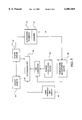
- FIG. 5 is a schematic of a feedback control system for a catheter including a plurality of ultrasound elements.
- FIG. 1A illustrates an ultrasound catheter 10 which includes a plurality of ultrasound elements 12, temperature sensors 13 and drug delivery ports 14 positioned along a selected section of the catheter 10.
- the catheter 10 also includes a guidewire lumen 15 which can accommodate a guidewire 16. At least one drug delivery port 14 is correlated with each ultrasound element 12.
- the ultrasound elements 12 and drug delivery ports 14 can be positioned adjacent a large lesion 18 in a vessel 20 as illustrated in FIG. 1B.
- Discrete ultrasound elements 12 are used in comparison to one continuous ultrasound element.
- Catheters introduced through circulatory vessels must be flexible in order to reach a desired location where the lesion 18 is located.
- a single ultrasound element which is long enough to deliver ultrasound energy the length of the lesion reduces the flexibility of the catheter 10. Therefore, multiple segmented ultrasound elements 12 provide an increased flexibility over a long single element.
- the average power required to activate an ultrasound element 12 is proportional to the activated area of the ultrasound element 12.
- a 2-cm long element requires approximately twice as much power as a 1-cm long element of similar shape and diameter.
- the diameter of the electrical wires that bring electrical energy to the ultrasound elements 12 must also increase. This requires an increase in catheter diameter that in turn reduces flexibility and restricts use of the catheter 10 in larger vessels.
- the ultrasound elements 12 are sized small enough so that they in combination with the catheter 10 provide a flexible structure that can be moved down a tortuous vein tree to the site of the lesion 18 or to any vessel in which there is a lengthy lesion 18 to be treated. Additionally, the ultrasound elements 12 are small enough that each individual ultrasound element 12, if excited individually, does not take an inordinate amount of power through the wires which supply power to the catheter 10. The ultrasound elements 12 are positioned to reduce dead space between the ultrasound elements 12. This provides some overlap in the radiation patterns that emit from each of the ultrasound elements 12 to maximize the enhancement effect.
- the ultrasound element 12 There is also a proximity between the ultrasound element 12 and the drug delivery ports 14 so that the drug emitted proximal or next to the catheter 10 is then affected by a nearby source of ultrasound energy.
- the drug delivery ports 14 do not need to be correlated with a particular ultrasound element 12 and there need be no relationship between the number of drug delivery ports 14 and the number of ultrasound elements 12.
- the ultrasound energy can be generated at an ultrasound energy source located external to the body and transmitted via wire to the ultrasound elements.
- Ultrasound can also be internally generated from electrical power delivered to the ultrasound elements from an electrical energy source.
- a suitable example of an ultrasound element for internal generation of ultrasound energy includes, but is not limited to, a piezoelectric ceramic oscillators.
- the ultrasound elements can be shaped as a cylinder, a hollow cylinder and a disk which are concentric with the catheter.
- the ultrasound elements can also be an array of smaller ultrasound elements or a thin plate positioned within the body of the catheter. Similarly, a single ultrasound element can be composed of several smaller ultrasound elements.
- the individual ultrasound elements 12 can each be individually powered. When the catheter includes N ultrasound elements, the catheter body must include 2N wires to individually power N ultrasound elements 12.
- the individual ultrasound elements 12 can also be electrically coupled in serial or in parallel as illustrated in FIGS. 2A and 2B. These arrangements permit maximum flexibility as they require only 2N wires.
- Each of the ultrasound elements receives power simultaneously whether the ultrasound elements are in series or in parallel. When the ultrasound elements 12 are in series, less current is required to produce the same power from each ultrasound element 12 than when the ultrasound elements 12 are connected in parallel. The reduced current allows smaller wires to be used to provide power to the ultrasound elements 12 and accordingly increases the flexibility of the catheter 10. When the ultrasound elements 12 are connected in parallel, an ultrasound element 12 can break down and the remaining ultrasound elements 12 will continue to operate.
- a common wire 22 can provide power to each of the ultrasound elements 12 while each ultrasound element 12 has its own return wire 24.
- a particular ultrasound elements 12 can be individually activated by closing a switch (not shown) to complete a circuit between the common wire 22 and the particular ultrasound element's return wire 24.
- a catheter with N ultrasound elements requires only N+1 wires and still permits independent control of the ultrasound elements 12. This reduced number of wires increases the flexibility of the catheter 10.
- the individual return wires can have diameters which are smaller than the common wire diameter. For instance, in an embodiment where N ultrasound elements will be powered simultaneously, the diameter of the individual wires can be the square root of N times smaller than the diameter of the common wire.
- a temperature sensor 13 is positioned adjacent each ultrasound element 12.
- Suitable temperature sensors 13 include, but are not limited to, thermistors, thermocouples and resistance temperature detectors, RTDs, and fiber optic temperature sensors which use thermalchromic liquid crystals.
- Suitable temperature sensor 13 geometries include, but are not limited to, a point, patch, stripe and a band around the catheter 10 as illustrated.
- the temperature sensors 13 can be positioned on the catheter 10, on the ultrasound element and adjacent the ultrasound elements 12 as illustrated.
- the temperature sensors 13 can be electrically connected as illustrated in FIG. 2C. Each temperature sensor 13 can be coupled with a common wire 22 and then include its own return wire 24. Accordingly, N+1 wires can be used to independently sense the temperature at the temperature sensors 13 of a catheter 10 having N temperature sensors 13.
- a suitable common wire 22 can be constructed from Constantine and suitable return 24 wires can be constructed from copper.
- the temperature at a particular temperature sensor 13 can be determined by closing a switch (not shown) to complete a circuit between the thermocouple's return wire 24 and the common wire 22. When the temperature sensors 13 are thermocouples, the temperature can be calculated form the voltage in the circuit.
- the individual return wires can have diameters which are smaller than the common wire diameter.
- Each temperature sensor 13 can also be independently wired.
- a catheter 10 including N temperature sensors 13 which are independently wired will require 2N wires to pass the length of the catheter.
- the catheter flexibility can also be improved by using fiber optic based temperature sensors.
- the flexibility can be improved because only N fiber optics need to be included in the catheter to sense the temperature at N temperature sensors.
- the temperature sensors 13 do not need to be correlated with the ultrasound elements 12.
- the catheter 10 can include a temperature sensor 13 which is positioned to provide a signal indicating the temperature of the portion of the lumen being treated.
- the temperature sensor 13 can be positioned between the central two ultrasound elements.
- the ultrasound output from the ultrasound elements 12 can be manually or automatically adjusted in response to the signal from the temperature sensor 13.
- the drug delivery ports 14 can be coupled with a common lumen 25 as illustrated in FIG. 3A.
- the drug delivery ports 14 can be positioned on one side of the catheter 10 or distributed about the surface of the catheter 10 to provide a more even delivery of the drug.
- a drug can be delivered through the common lumen 25 to the various drug delivery ports 14 next to each of the ultrasound elements 12 so that all of the drug delivery ports 14 deliver drug at the same time.
- one or more drug delivery ports 26 can be coupled with a first lumen 27 and one or more second drug delivery ports 28 can be coupled with a second lumen 29. Accordingly, different drugs can be delivered adjacent different ultrasound elements 12. Further, different amounts of the same drug can be delivered adjacent particular ultrasound elements 12. As a result, the amount of drug delivery can be adjusted to match the amount of therapeutic treatment required by a particular section of the lesion 18.
- Use of the ultrasound elements 12 and a plurality of drug delivery ports 14 can provide controllability and selectability of lesion modification/destruction.
- the catheter 10 can be used in various body structures and body lumens including, but not limited to, the pancreas, sinuses, esophagus, rectum, gastrointestinal vessels and urological vessels.
- the catheter 10 is selected from a variety of different sizes, diameter and length, depending on the type and location of the lesion 18.
- An active length of catheter 10 is defined by the number and spacing of the ultrasound elements 12 and drug delivery ports 14 at the distal end.
- the number of ultrasound elements 12 depends on the length of the vessel being treated. Suitable numbers of ultrasound elements include, but are not limited to 2-10, 2-8 and 4-6.
- Each of the ultrasound elements 12 can be from one millimeter in length to up to a half centimeter in length. Other dimensions can also be used.
- the spacing between ultrasound elements 12 can be approximately equal to the length of each ultrasound element 12. If one ultrasound element 12 has a length L, a second ultrasound element 12 can be spaced up to three L lengths away from the first ultrasound element 12. Suitable L include, bur are not limited to 0.2-2 cm, 0.2-1.2 cm and 0.3-0.7 cm.
- the catheter 10 can be constructed to overcome the reduced flexibility which results from the multiple ultrasound elements 12.
- the catheter 10 can include ribs 30 between the ultrasound elements 12.
- the ribs 30 increase the bendability of the catheter at the ribbed locations while providing kink resistance.
- the added flexibility can be necessary to work the catheter 10 through tortuous vessels.
- additional flexibility can be obtained by manufacturing at least the portion of the catheter 10 between the ultrasound elements 12 from a mesh 32 or braided material.
- the outer surface of the catheter 10 and the lumens within the catheter 10 are smooth 34. The smooth surfaces 34 aid in passing the catheter 10 through the body lumen and in passing fluids through the lumen.
- Suitable materials for the catheter include, but are not limited to polyolefins and polyimides and other low acoustic impedance materials. Low accoustic impedance materials are materials which readily transmit ultrasound energy with minimal absorption of the energy.
- Suitable materials for the mesh or braid include, but are not limited to Kevlar, stainless steel, polyetheretherketone or PEEK. Cotton braided with polymer can also serve to provide flexibility and kink resistance.
- the ultrasound elements 12 can be positioned internally or externally to catheter 10, and can have any number of different geometric designs. Suitable, geometric designs include, but are not limited to a band which lies flush with the circumference of the catheter. Additionally, ultrasound elements 12 can be designed provide any desired directionality of ultrasound.
- the catheter 10 can be coupled with an open or closed loop feedback system.
- an open or closed loop feedback system couples temperature sensor 13 to an energy source 40.
- the temperature of the tissue, or of each ultrasound element 12 is monitored, and the output power of energy source 40 adjusted accordingly.
- the physician can, if desired, override the closed or open loop system.
- a processing unit 42 can be included and incorporated in the closed or open loop system to switch power on and off, as well as modulate the power.
- the processing unit 42 includes logic for monitoring the temperature at each temperature sensor 13, adjusting the power delivered to each ultrasound element 12, re-monitoring the temperature at each temperature sensor 13 and re-adjusting the power delivered to the ultrasound elements 12 in response to the re-monitored temperature.
- the tissue adjacent to the ultrasound elements 12 can be maintained at a desired temperature for a selected period of time.
- Each ultrasound element 12 is connected to resources which generate an independent output. The output maintains a selected energy at each ultrasound element 12 for a selected length of time.
- Power delivered to the ultrasound elements 12 is measured by the power calculation device 44.
- the power can then be displayed at user interface and display 46.
- Signals representative of power and impedance values are received by the processing unit 42.
- a control signal is generated by the processing unit 42 that is proportional to the difference between an actual measured value, and a desired value.
- the control signal is used by power circuits 47 to adjust the power output in an appropriate amount in order to maintain the temperature at each ultrasound element 12 within a desired range.
- the temperatures detected at the temperature sensors 13 provide feedback for maintaining the desired temperature range.
- the temperature at each temperature sensor 12 can be used as safety devices to interrupt the delivery of energy when maximum pre-set temperatures are exceeded.
- the temperature at each ultrasound sensor 12 is measured at temperature measurement device 48, and can be displayed at user interface and display 46.
- a temperature control signal is generated by the processing unit 42 that is proportional to the difference between an actual measured temperature and a desired temperature.
- the temperature control signal is used to determine the desired power. For instance, when the control signal exceeds a pre-determined level, the desired power supplied to a particular ultrasound element can be reduced or turned off. Similarly, when the control signal falls below a pre-determined level, the desired power supplied to a particular ultrasound element 12 can be increased or turned on.
- the processing unit 42 can be a digital or analog controller, or a computer with software.
- the processing unit 42 can include a CPU coupled through a system bus.
- On this system can be a keyboard, a disk drive, or other non-volatile memory systems, a display, and other peripherals, as are known in the art.
- Also coupled to the bus is a program memory and a data memory.
- User interface and display 46 includes operator controls and a display.
- the output of the temperature sensors 13 is used by the processing unit 42 to maintain a selected temperature range at each temperature sensor 13.
- a profile of the power delivered to each ultrasound element 12 can be incorporated in the processing unit 42 and a preset amount of energy to be delivered may also be profiled.
- Circuitry, software and feedback to the processing unit 42 result in process control, and the maintenance of the selected power setting that is independent of changes in voltage or current, and used to change, (i) the selected power setting, (ii) the duty cycle (on-off time), (iii) bipolar or monopolar energy delivery and (iv) fluid delivery, including flow rate and pressure.
- process variables are controlled and varied, while maintaining the desired delivery of power independent of changes in voltage or current, based on temperatures monitored at the temperature sensor 13.
- the catheter 10 is guided along the artery or vein to the lesion site by fluoroscopy. Radio opaque markers may be used with the catheter 10 next to each of the ultrasound elements 12, or in the case of certain piezoelectric elements 12, the ultrasound elements 12 themselves are radio opaque and readily identified and also readily identify the site of the adjacent drug port 14.
- the catheter 10 is advanced through the vessel with the assistance of a guidewire. The catheter can be advanced until each of the ultrasound elements are adjacent the lesion or until only a portion of the ultrasound elements are adjacent the lesion.
- the drug is hydraulically delivered through the lumen to the drug delivery ports 14.
- the ultrasound elements 12 are then all turned on together, sequenced or multiplexed according to the preferred treatment by the physician.
- the feedback control system is then engaged to control the temperature of within the vessel.
- the catheter 10 remains in place for the treatment period and the drug can be continually infused with the ultrasound elements 12 on, off, partially on, or partially off.
- the catheter can be advanced to treat additional untreated portions of the vessel.
- the ultrasound elements which are used to treat the additional untreated portion can be different from the ultrasound elements used during the initial treatment(s).
- the catheter 10 is removed.
- Segmentation of ultrasound elements 12 greatly reduces the required amount of a lumen of the catheter 10 that is used for segment wiring, increases the flexibility of the catheter 10, and permits radiation of a long lesion 18.
- the power requirements necessitate the use of thick wires. This is eliminated with the use of ultrasound elements 12 in segment form.
- Replacement of one large wire by multiple wires of equivalent cross-sectional area or a cumulated cross-section area is more flexible and also avoids having to excite entirely a long ultrasound element, smaller ultrasound elements 12 that are segmented are used. Therefore, a fraction of the power at any one time is needed, depending on the number of ultrasound elements 12 activated.
Abstract
Description
Claims (22)
Priority Applications (9)
| Application Number | Priority Date | Filing Date | Title |
|---|---|---|---|
| US09/071,285 US6001069A (en) | 1997-05-01 | 1998-05-01 | Ultrasound catheter for providing a therapeutic effect to a vessel of a body |
| US09/374,642 US6676626B1 (en) | 1998-05-01 | 1999-08-16 | Ultrasound assembly with increased efficacy |
| US09/375,162 US6582392B1 (en) | 1998-05-01 | 1999-08-16 | Ultrasound assembly for use with a catheter |
| US10/383,292 US20030167023A1 (en) | 1997-05-01 | 2003-03-06 | Ultrasound catheter for providing a therapeutic effect to a vessel of a body |
| US10/383,295 US7186246B2 (en) | 1997-05-01 | 2003-03-06 | Ultrasound catheter with utility lumen |
| US10/735,588 US7976483B2 (en) | 1997-05-01 | 2003-12-12 | Ultrasound assembly with increased efficacy |
| US11/707,189 US7914509B2 (en) | 1997-05-01 | 2007-02-15 | Ultrasound catheter |
| US13/333,922 US8690818B2 (en) | 1997-05-01 | 2011-12-21 | Ultrasound catheter for providing a therapeutic effect to a vessel of a body |
| US14/170,419 US20140155814A1 (en) | 1997-05-01 | 2014-01-31 | Ultrasound catheter for providing a therapeutic effect to a vessel of a body |
Applications Claiming Priority (2)
| Application Number | Priority Date | Filing Date | Title |
|---|---|---|---|
| US4526897P | 1997-05-01 | 1997-05-01 | |
| US09/071,285 US6001069A (en) | 1997-05-01 | 1998-05-01 | Ultrasound catheter for providing a therapeutic effect to a vessel of a body |
Related Child Applications (3)
| Application Number | Title | Priority Date | Filing Date |
|---|---|---|---|
| US09/107,078 Continuation-In-Part US6723063B1 (en) | 1997-05-01 | 1998-06-29 | Sheath for use with an ultrasound element |
| US09/375,162 Continuation-In-Part US6582392B1 (en) | 1997-05-01 | 1999-08-16 | Ultrasound assembly for use with a catheter |
| US09/374,642 Continuation-In-Part US6676626B1 (en) | 1997-05-01 | 1999-08-16 | Ultrasound assembly with increased efficacy |
Publications (1)
| Publication Number | Publication Date |
|---|---|
| US6001069A true US6001069A (en) | 1999-12-14 |
Family
ID=21936919
Family Applications (1)
| Application Number | Title | Priority Date | Filing Date |
|---|---|---|---|
| US09/071,285 Expired - Lifetime US6001069A (en) | 1997-05-01 | 1998-05-01 | Ultrasound catheter for providing a therapeutic effect to a vessel of a body |
Country Status (2)
| Country | Link |
|---|---|
| US (1) | US6001069A (en) |
| WO (1) | WO1998048711A1 (en) |
Cited By (128)
| Publication number | Priority date | Publication date | Assignee | Title |
|---|---|---|---|---|
| WO2001013357A1 (en) | 1999-08-16 | 2001-02-22 | Ekos Corporation | Ultrasound assembly for use with a catheter |
| US6193683B1 (en) * | 1999-07-28 | 2001-02-27 | Allergan | Closed loop temperature controlled phacoemulsification system to prevent corneal burns |
| US6296619B1 (en) | 1998-12-30 | 2001-10-02 | Pharmasonics, Inc. | Therapeutic ultrasonic catheter for delivering a uniform energy dose |
| WO2001085255A1 (en) * | 2000-05-09 | 2001-11-15 | Radi Medical Technologies Ab | Radiation therapy device with miniaturized radiation source |
| US6322513B1 (en) * | 1999-01-25 | 2001-11-27 | Werner Schregel | Blood-vessel catheter |
| WO2002019927A1 (en) * | 2000-09-05 | 2002-03-14 | Calluna Ide Ab | Method and device for chemical dispersion of a gel in an organic structure |
| WO2002041947A2 (en) * | 2000-11-22 | 2002-05-30 | Sarnoff Corporation | Method and apparatus for delivering localized x-ray radiation to the interior of a body |
| WO2002043796A2 (en) | 2000-11-28 | 2002-06-06 | Scimed Life Systems, Inc. | Balloon catheter having micro-needles on the balloon surface for delivery of a biologically active material to a body lumen |
| WO2002062241A1 (en) * | 2001-02-08 | 2002-08-15 | Tyco Healthcare Group Lp | Ultrasonic surgical instrument |
| US6478754B1 (en) | 2001-04-23 | 2002-11-12 | Advanced Medical Applications, Inc. | Ultrasonic method and device for wound treatment |
| US6527759B1 (en) | 1995-03-05 | 2003-03-04 | Ekos Corporation | Ultrasound assembly for use with light activated drugs |
| US6533803B2 (en) | 2000-12-22 | 2003-03-18 | Advanced Medical Applications, Inc. | Wound treatment method and device with combination of ultrasound and laser energy |
| WO2003047696A1 (en) | 2001-12-03 | 2003-06-12 | Ekos Corporation | Small vessel ultrasound catheter |
| WO2003047439A2 (en) | 2001-12-03 | 2003-06-12 | Ekos Corporation | Catheter with multiple ultrasound radiating members |
| WO2003051208A1 (en) | 2001-12-14 | 2003-06-26 | Ekos Corporation | Blood flow reestablishment determination |
| US6601581B1 (en) | 2000-11-01 | 2003-08-05 | Advanced Medical Applications, Inc. | Method and device for ultrasound drug delivery |
| WO2003072165A2 (en) * | 2002-02-28 | 2003-09-04 | Ekos Corporation | Ultrasound assembly for use with a catheter |
| US6623444B2 (en) | 2001-03-21 | 2003-09-23 | Advanced Medical Applications, Inc. | Ultrasonic catheter drug delivery method and device |
| US20030187368A1 (en) * | 2000-06-12 | 2003-10-02 | Masataka Sata | Medical guide wire doubling as a catheter |
| US20030215459A1 (en) * | 1997-10-24 | 2003-11-20 | Anthony Atala | Methods for promoting cell transfection in vivo |
| US6663578B1 (en) * | 2002-10-11 | 2003-12-16 | Koninklijke Philips Electronics N.V. | Operator supervised temperature control system and method for an ultrasound transducer |
| US6669638B1 (en) * | 2002-10-10 | 2003-12-30 | Koninklijke Philips Electronics N.V. | Imaging ultrasound transducer temperature control system and method |
| US20040002677A1 (en) * | 2001-12-11 | 2004-01-01 | Gentsler Curtis C. | Alternate site gene therapy |
| US20040019318A1 (en) * | 2001-11-07 | 2004-01-29 | Wilson Richard R. | Ultrasound assembly for use with a catheter |
| US6709392B1 (en) * | 2002-10-10 | 2004-03-23 | Koninklijke Philips Electronics N.V. | Imaging ultrasound transducer temperature control system and method using feedback |
| US20040073114A1 (en) * | 2001-12-28 | 2004-04-15 | Oliver Leonard R. | Multi-resonant ultrasonic catheter |
| US20040077976A1 (en) * | 2002-10-14 | 2004-04-22 | Wilson Richard R. | Ultrasound radiating members for catheter |
| US6761729B2 (en) | 2000-12-22 | 2004-07-13 | Advanced Medicalapplications, Inc. | Wound treatment method and device with combination of ultrasound and laser energy |
| WO2004093656A2 (en) * | 2003-04-22 | 2004-11-04 | Ekos Corporation | Ultrasound enhanced central venous catheter |
| US20050020890A1 (en) * | 2001-10-08 | 2005-01-27 | Werner Schregel | Device for introducing into hollow organs of the body |
| WO2004060448A3 (en) * | 2003-01-03 | 2005-03-31 | Ekos Corp | Ultrasonic catheter with axial energy field |
| US20050137520A1 (en) * | 2003-10-29 | 2005-06-23 | Rule Peter R. | Catheter with ultrasound-controllable porous membrane |
| US20050192556A1 (en) * | 2004-01-30 | 2005-09-01 | Azita Soltani | Treatment of vascular occlusions using ultrasonic energy and microbubbles |
| US20050197577A1 (en) * | 2004-03-08 | 2005-09-08 | Makin Inder Raj S. | Intra-cavitary ultrasound medical system and method |
| US20050215942A1 (en) * | 2004-01-29 | 2005-09-29 | Tim Abrahamson | Small vessel ultrasound catheter |
| US20050215946A1 (en) * | 2004-01-29 | 2005-09-29 | Hansmann Douglas R | Method and apparatus for detecting vascular conditions with a catheter |
| US20050240151A1 (en) * | 2004-01-29 | 2005-10-27 | Hansmann Douglas R | Treatment of vascular occlusions using elevated temperatures |
| US20050261610A1 (en) * | 2004-05-21 | 2005-11-24 | Mast T D | Transmit apodization of an ultrasound transducer array |
| US20060264809A1 (en) * | 2005-04-12 | 2006-11-23 | Hansmann Douglas R | Ultrasound catheter with cavitation promoting surface |
| US20070005121A1 (en) * | 2002-04-29 | 2007-01-04 | Rohit Khanna | Central nervous system cooling catheter |
| US20070083120A1 (en) * | 2005-09-22 | 2007-04-12 | Cain Charles A | Pulsed cavitational ultrasound therapy |
| US20070135879A1 (en) * | 2005-12-08 | 2007-06-14 | Mcintyre Jon T | Cylindrical device for delivering energy to tissue |
| US20080171965A1 (en) * | 2007-01-08 | 2008-07-17 | Ekos Corporation | Power parameters for ultrasonic catheter |
| US7413556B2 (en) | 1998-06-29 | 2008-08-19 | Ekos Corporation | Sheath for use with an ultrasound element |
| US20080214967A1 (en) * | 2004-02-17 | 2008-09-04 | Ernest Aranyi | Ultrasonic surgical instrument |
| US20080274097A1 (en) * | 1991-03-22 | 2008-11-06 | Katsuro Tachibana | Booster for therapy of diseases with ultrasound and pharmaceutical liquid composition containing the same |
| US20090018472A1 (en) * | 2007-01-08 | 2009-01-15 | Azita Soltani | Power parameters for ultrasonic catheter |
| US20090177085A1 (en) * | 2005-09-22 | 2009-07-09 | Adam Maxwell | Histotripsy for thrombolysis |
| US7713218B2 (en) | 2005-06-23 | 2010-05-11 | Celleration, Inc. | Removable applicator nozzle for ultrasound wound therapy device |
| US7749249B2 (en) | 2006-02-21 | 2010-07-06 | Kardium Inc. | Method and device for closing holes in tissue |
| US7785278B2 (en) | 2006-06-07 | 2010-08-31 | Bacoustics, Llc | Apparatus and methods for debridement with ultrasound energy |
| US7785277B2 (en) | 2005-06-23 | 2010-08-31 | Celleration, Inc. | Removable applicator nozzle for ultrasound wound therapy device |
| US7806892B2 (en) | 2001-05-29 | 2010-10-05 | Ethicon Endo-Surgery, Inc. | Tissue-retaining system for ultrasound medical treatment |
| US7806839B2 (en) | 2004-06-14 | 2010-10-05 | Ethicon Endo-Surgery, Inc. | System and method for ultrasound therapy using grating lobes |
| US7837610B2 (en) | 2006-08-02 | 2010-11-23 | Kardium Inc. | System for improving diastolic dysfunction |
| US7846096B2 (en) | 2001-05-29 | 2010-12-07 | Ethicon Endo-Surgery, Inc. | Method for monitoring of medical treatment using pulse-echo ultrasound |
| US7883468B2 (en) | 2004-05-18 | 2011-02-08 | Ethicon Endo-Surgery, Inc. | Medical system having an ultrasound source and an acoustic coupling medium |
| US7914470B2 (en) | 2001-01-12 | 2011-03-29 | Celleration, Inc. | Ultrasonic method and device for wound treatment |
| US7914509B2 (en) | 1997-05-01 | 2011-03-29 | Ekos Corporation | Ultrasound catheter |
| US20110082414A1 (en) * | 2009-10-06 | 2011-04-07 | Wallace Michael P | Ultrasound-enhanced stenosis therapy |
| US20110082534A1 (en) * | 2009-10-06 | 2011-04-07 | Wallace Michael P | Ultrasound-enhanced stenosis therapy |
| US20110082396A1 (en) * | 2009-10-06 | 2011-04-07 | Wallace Michael P | Ultrasound-enhanced stenosis therapy |
| US20110105960A1 (en) * | 2009-10-06 | 2011-05-05 | Wallace Michael P | Ultrasound-enhanced Stenosis therapy |
| US7951095B2 (en) | 2004-05-20 | 2011-05-31 | Ethicon Endo-Surgery, Inc. | Ultrasound medical system |
| US7976483B2 (en) | 1997-05-01 | 2011-07-12 | Ekos Corporation | Ultrasound assembly with increased efficacy |
| US8057408B2 (en) | 2005-09-22 | 2011-11-15 | The Regents Of The University Of Michigan | Pulsed cavitational ultrasound therapy |
| US8150499B2 (en) * | 2006-05-19 | 2012-04-03 | Kardium Inc. | Automatic atherectomy system |
| US8192363B2 (en) | 2006-10-27 | 2012-06-05 | Ekos Corporation | Catheter with multiple ultrasound radiating members |
| US8192391B2 (en) | 2009-07-03 | 2012-06-05 | Ekos Corporation | Power parameters for ultrasonic catheter |
| US8226629B1 (en) | 2002-04-01 | 2012-07-24 | Ekos Corporation | Ultrasonic catheter power control |
| US8235919B2 (en) | 2001-01-12 | 2012-08-07 | Celleration, Inc. | Ultrasonic method and device for wound treatment |
| US20120289889A1 (en) * | 2011-05-11 | 2012-11-15 | Ekos Corporation | Ultrasound system |
| US8449605B2 (en) | 2006-06-28 | 2013-05-28 | Kardium Inc. | Method for anchoring a mitral valve |
| US8489172B2 (en) | 2008-01-25 | 2013-07-16 | Kardium Inc. | Liposuction system |
| US8491521B2 (en) | 2007-01-04 | 2013-07-23 | Celleration, Inc. | Removable multi-channel applicator nozzle |
| US8539813B2 (en) | 2009-09-22 | 2013-09-24 | The Regents Of The University Of Michigan | Gel phantoms for testing cavitational ultrasound (histotripsy) transducers |
| US8562547B2 (en) | 2006-06-07 | 2013-10-22 | Eliaz Babaev | Method for debriding wounds |
| EP2727544A1 (en) | 2012-11-05 | 2014-05-07 | Ekos Corporation | Catheter systems and methods |
| US8740835B2 (en) | 2010-02-17 | 2014-06-03 | Ekos Corporation | Treatment of vascular occlusions using ultrasonic energy and microbubbles |
| US8906011B2 (en) | 2007-11-16 | 2014-12-09 | Kardium Inc. | Medical device for use in bodily lumens, for example an atrium |
| US8920411B2 (en) | 2006-06-28 | 2014-12-30 | Kardium Inc. | Apparatus and method for intra-cardiac mapping and ablation |
| US8940002B2 (en) | 2010-09-30 | 2015-01-27 | Kardium Inc. | Tissue anchor system |
| US9011423B2 (en) | 2012-05-21 | 2015-04-21 | Kardium, Inc. | Systems and methods for selecting, activating, or selecting and activating transducers |
| US9044568B2 (en) | 2007-06-22 | 2015-06-02 | Ekos Corporation | Method and apparatus for treatment of intracranial hemorrhages |
| US9049783B2 (en) | 2012-04-13 | 2015-06-02 | Histosonics, Inc. | Systems and methods for obtaining large creepage isolation on printed circuit boards |
| US9050066B2 (en) | 2010-06-07 | 2015-06-09 | Kardium Inc. | Closing openings in anatomical tissue |
| US20150165161A1 (en) * | 2006-04-21 | 2015-06-18 | Bayer Medical Care Inc. | Catheters And Related Equipment |
| US9061131B2 (en) | 2009-08-17 | 2015-06-23 | Histosonics, Inc. | Disposable acoustic coupling medium container |
| US9072511B2 (en) | 2011-03-25 | 2015-07-07 | Kardium Inc. | Medical kit for constricting tissue or a bodily orifice, for example, a mitral valve |
| US9119633B2 (en) | 2006-06-28 | 2015-09-01 | Kardium Inc. | Apparatus and method for intra-cardiac mapping and ablation |
| US9144694B2 (en) | 2011-08-10 | 2015-09-29 | The Regents Of The University Of Michigan | Lesion generation through bone using histotripsy therapy without aberration correction |
| US9198592B2 (en) | 2012-05-21 | 2015-12-01 | Kardium Inc. | Systems and methods for activating transducers |
| US9204964B2 (en) | 2009-10-01 | 2015-12-08 | Kardium Inc. | Medical device, kit and method for constricting tissue or a bodily orifice, for example, a mitral valve |
| US9375223B2 (en) | 2009-10-06 | 2016-06-28 | Cardioprolific Inc. | Methods and devices for endovascular therapy |
| US9452016B2 (en) | 2011-01-21 | 2016-09-27 | Kardium Inc. | Catheter system |
| US9480525B2 (en) | 2011-01-21 | 2016-11-01 | Kardium, Inc. | High-density electrode-based medical device system |
| US9492228B2 (en) | 2011-01-21 | 2016-11-15 | Kardium Inc. | Enhanced medical device for use in bodily cavities, for example an atrium |
| US20160374703A1 (en) * | 2014-03-20 | 2016-12-29 | Agency For Science, Technology And Research | Thrombolysis device and method of operating a thrombolysis device |
| USD777925S1 (en) | 2012-01-20 | 2017-01-31 | Kardium Inc. | Intra-cardiac procedure device |
| USD777926S1 (en) | 2012-01-20 | 2017-01-31 | Kardium Inc. | Intra-cardiac procedure device |
| US9579494B2 (en) | 2013-03-14 | 2017-02-28 | Ekos Corporation | Method and apparatus for drug delivery to a target site |
| US20170113069A1 (en) * | 2014-07-18 | 2017-04-27 | Olympus Corporation | Ultrasonic energy therapy device and ultrasonic energy therapy method |
| US9636133B2 (en) | 2012-04-30 | 2017-05-02 | The Regents Of The University Of Michigan | Method of manufacturing an ultrasound system |
| US9744038B2 (en) | 2008-05-13 | 2017-08-29 | Kardium Inc. | Medical device for constricting tissue or a bodily orifice, for example a mitral valve |
| US9901753B2 (en) | 2009-08-26 | 2018-02-27 | The Regents Of The University Of Michigan | Ultrasound lithotripsy and histotripsy for using controlled bubble cloud cavitation in fractionating urinary stones |
| US9943708B2 (en) | 2009-08-26 | 2018-04-17 | Histosonics, Inc. | Automated control of micromanipulator arm for histotripsy prostate therapy while imaging via ultrasound transducers in real time |
| US10028783B2 (en) | 2006-06-28 | 2018-07-24 | Kardium Inc. | Apparatus and method for intra-cardiac mapping and ablation |
| US10092742B2 (en) | 2014-09-22 | 2018-10-09 | Ekos Corporation | Catheter system |
| US10232196B2 (en) | 2006-04-24 | 2019-03-19 | Ekos Corporation | Ultrasound therapy system |
| US10293187B2 (en) | 2013-07-03 | 2019-05-21 | Histosonics, Inc. | Histotripsy excitation sequences optimized for bubble cloud formation using shock scattering |
| US10322230B2 (en) | 2016-06-09 | 2019-06-18 | C. R. Bard, Inc. | Systems and methods for correcting and preventing occlusion in a catheter |
| US10368936B2 (en) | 2014-11-17 | 2019-08-06 | Kardium Inc. | Systems and methods for selecting, activating, or selecting and activating transducers |
| US10656025B2 (en) | 2015-06-10 | 2020-05-19 | Ekos Corporation | Ultrasound catheter |
| US10722184B2 (en) | 2014-11-17 | 2020-07-28 | Kardium Inc. | Systems and methods for selecting, activating, or selecting and activating transducers |
| US10780298B2 (en) | 2013-08-22 | 2020-09-22 | The Regents Of The University Of Michigan | Histotripsy using very short monopolar ultrasound pulses |
| US10827977B2 (en) | 2012-05-21 | 2020-11-10 | Kardium Inc. | Systems and methods for activating transducers |
| US10888657B2 (en) | 2010-08-27 | 2021-01-12 | Ekos Corporation | Method and apparatus for treatment of intracranial hemorrhages |
| CN112438777A (en) * | 2019-08-28 | 2021-03-05 | 尤东侠 | Minimally invasive thrombus extraction device for treating vascular embolism |
| US11039845B2 (en) | 2009-10-06 | 2021-06-22 | Cardioprolific Inc. | Methods and devices for endovascular therapy |
| US11058399B2 (en) | 2012-10-05 | 2021-07-13 | The Regents Of The University Of Michigan | Bubble-induced color doppler feedback during histotripsy |
| US11135454B2 (en) | 2015-06-24 | 2021-10-05 | The Regents Of The University Of Michigan | Histotripsy therapy systems and methods for the treatment of brain tissue |
| US11224767B2 (en) | 2013-11-26 | 2022-01-18 | Sanuwave Health, Inc. | Systems and methods for producing and delivering ultrasonic therapies for wound treatment and healing |
| US11259867B2 (en) | 2011-01-21 | 2022-03-01 | Kardium Inc. | High-density electrode-based medical device system |
| WO2022103970A1 (en) * | 2020-11-12 | 2022-05-19 | Bard Access Systems, Inc. | Medical systems and methods thereof for ultrasonic decomposition of intraluminal clots |
| US11389232B2 (en) | 2006-06-28 | 2022-07-19 | Kardium Inc. | Apparatus and method for intra-cardiac mapping and ablation |
| US11432900B2 (en) | 2013-07-03 | 2022-09-06 | Histosonics, Inc. | Articulating arm limiter for cavitational ultrasound therapy system |
| US11648424B2 (en) | 2018-11-28 | 2023-05-16 | Histosonics Inc. | Histotripsy systems and methods |
| US11813485B2 (en) | 2020-01-28 | 2023-11-14 | The Regents Of The University Of Michigan | Systems and methods for histotripsy immunosensitization |
Families Citing this family (9)
| Publication number | Priority date | Publication date | Assignee | Title |
|---|---|---|---|---|
| WO1998048711A1 (en) * | 1997-05-01 | 1998-11-05 | Ekos Corporation | Ultrasound catheter |
| US6575956B1 (en) | 1997-12-31 | 2003-06-10 | Pharmasonics, Inc. | Methods and apparatus for uniform transcutaneous therapeutic ultrasound |
| JP2001526926A (en) | 1997-12-31 | 2001-12-25 | ファーマソニックス,インコーポレイテッド | Methods and systems for suppressing vascular hyperplasia |
| US6312402B1 (en) | 1998-09-24 | 2001-11-06 | Ekos Corporation | Ultrasound catheter for improving blood flow to the heart |
| JP2002536040A (en) * | 1999-02-02 | 2002-10-29 | トランサージカル,インコーポレイテッド | High intensity focused ultrasound applicator in the body |
| US6387116B1 (en) | 1999-06-30 | 2002-05-14 | Pharmasonics, Inc. | Methods and kits for the inhibition of hyperplasia in vascular fistulas and grafts |
| IL141123A0 (en) * | 2001-01-26 | 2002-02-10 | Iger Yoni | Method and apparatus for the delivery of substances to biological components |
| US7135029B2 (en) | 2001-06-29 | 2006-11-14 | Makin Inder Raj S | Ultrasonic surgical instrument for intracorporeal sonodynamic therapy |
| WO2007144883A1 (en) * | 2006-06-13 | 2007-12-21 | Ben Gurion University Of The Negev Research And Development Authority | System and method for transfetal (amnion-chorion) membranes transport |
Citations (62)
| Publication number | Priority date | Publication date | Assignee | Title |
|---|---|---|---|---|
| US3433226A (en) * | 1965-07-21 | 1969-03-18 | Aeroprojects Inc | Vibratory catheterization apparatus and method of using |
| US4040414A (en) * | 1976-05-12 | 1977-08-09 | Xygiene, Inc. | Ultrasonic personal care instrument and method |
| US4319580A (en) * | 1979-08-28 | 1982-03-16 | The Board Of Regents Of The University Of Washington | Method for detecting air emboli in the blood in an intracorporeal blood vessel |
| US4354502A (en) * | 1979-08-28 | 1982-10-19 | The Board Of Regents Of The University Of Washington | Intravascular catheter including untrasonic transducer for use in detection and aspiration of air emboli |
| US4531943A (en) * | 1983-08-08 | 1985-07-30 | Angiomedics Corporation | Catheter with soft deformable tip |
| US4549533A (en) * | 1984-01-30 | 1985-10-29 | University Of Illinois | Apparatus and method for generating and directing ultrasound |
| US4750902A (en) * | 1985-08-28 | 1988-06-14 | Sonomed Technology, Inc. | Endoscopic ultrasonic aspirators |
| US4808153A (en) * | 1986-11-17 | 1989-02-28 | Ultramed Corporation | Device for removing plaque from arteries |
| WO1989004142A1 (en) * | 1987-11-11 | 1989-05-18 | Circulation Research Limited | Methods and apparatus for the examination and treatment of internal organs |
| US4870953A (en) * | 1987-11-13 | 1989-10-03 | Donmicheal T Anthony | Intravascular ultrasonic catheter/probe and method for treating intravascular blockage |
| US4920954A (en) * | 1988-08-05 | 1990-05-01 | Sonic Needle Corporation | Ultrasonic device for applying cavitation forces |
| US4924863A (en) * | 1988-05-04 | 1990-05-15 | Mmtc, Inc. | Angioplastic method for removing plaque from a vas |
| US4936281A (en) * | 1989-04-13 | 1990-06-26 | Everest Medical Corporation | Ultrasonically enhanced RF ablation catheter |
| US5021044A (en) * | 1989-01-30 | 1991-06-04 | Advanced Cardiovascular Systems, Inc. | Catheter for even distribution of therapeutic fluids |
| DE4005743A1 (en) * | 1990-02-23 | 1991-08-29 | Wolf Gmbh Richard | Lithotriptor to destroy gallstones intra-or trans-luminally - has shock-wave generator, lead contg. incompressible material, and opt balloon to press generator against gall bladder |
| US5163421A (en) * | 1988-01-22 | 1992-11-17 | Angiosonics, Inc. | In vivo ultrasonic system with angioplasty and ultrasonic contrast imaging |
| EP0529675A2 (en) * | 1991-08-29 | 1993-03-03 | Ethicon, Inc. | Shape memory effect surgical needles |
| US5197946A (en) * | 1990-06-27 | 1993-03-30 | Shunro Tachibana | Injection instrument with ultrasonic oscillating element |
| US5207214A (en) * | 1991-03-19 | 1993-05-04 | Romano Anthony J | Synthesizing array for three-dimensional sound field specification |
| US5250034A (en) * | 1990-09-17 | 1993-10-05 | E-Z-Em, Inc. | Pressure responsive valve catheter |
| US5267954A (en) * | 1991-01-11 | 1993-12-07 | Baxter International Inc. | Ultra-sound catheter for removing obstructions from tubular anatomical structures such as blood vessels |
| US5267985A (en) * | 1993-02-11 | 1993-12-07 | Trancell, Inc. | Drug delivery by multiple frequency phonophoresis |
| US5269291A (en) * | 1990-12-10 | 1993-12-14 | Coraje, Inc. | Miniature ultrasonic transducer for plaque ablation |
| US5282785A (en) * | 1990-06-15 | 1994-02-01 | Cortrak Medical, Inc. | Drug delivery apparatus and method |
| US5295484A (en) * | 1992-05-19 | 1994-03-22 | Arizona Board Of Regents For And On Behalf Of The University Of Arizona | Apparatus and method for intra-cardiac ablation of arrhythmias |
| US5304115A (en) * | 1991-01-11 | 1994-04-19 | Baxter International Inc. | Ultrasonic angioplasty device incorporating improved transmission member and ablation probe |
| US5307816A (en) * | 1991-08-21 | 1994-05-03 | Kabushiki Kaisha Toshiba | Thrombus resolving treatment apparatus |
| US5318014A (en) * | 1992-09-14 | 1994-06-07 | Coraje, Inc. | Ultrasonic ablation/dissolution transducer |
| US5323769A (en) * | 1990-02-23 | 1994-06-28 | Cygnus Therapeutic Systems | Ultrasound-enhanced delivery of materials into and through the skin |
| US5327891A (en) * | 1992-07-30 | 1994-07-12 | Rammler David H | Catheter track and catheter for diagnosis and treatment |
| US5328470A (en) * | 1989-03-31 | 1994-07-12 | The Regents Of The University Of Michigan | Treatment of diseases by site-specific instillation of cells or site-specific transformation of cells and kits therefor |
| US5344435A (en) * | 1988-07-28 | 1994-09-06 | Bsd Medical Corporation | Urethral inserted applicator prostate hyperthermia |
| US5345940A (en) * | 1991-11-08 | 1994-09-13 | Mayo Foundation For Medical Education And Research | Transvascular ultrasound hemodynamic and interventional catheter and method |
| US5353798A (en) * | 1991-03-13 | 1994-10-11 | Scimed Life Systems, Incorporated | Intravascular imaging apparatus and methods for use and manufacture |
| US5354279A (en) * | 1992-10-21 | 1994-10-11 | Bavaria Medizin Technologie Gmbh | Plural needle injection catheter |
| US5362309A (en) * | 1992-09-14 | 1994-11-08 | Coraje, Inc. | Apparatus and method for enhanced intravascular phonophoresis including dissolution of intravascular blockage and concomitant inhibition of restenosis |
| US5363853A (en) * | 1991-11-08 | 1994-11-15 | Baxter International Inc. | Ultrasound probe for use with transport catheter and method of making same |
| EP0629382A1 (en) * | 1992-08-12 | 1994-12-21 | Vidamed, Inc. | Medical probe device and method |
| US5380273A (en) * | 1992-05-19 | 1995-01-10 | Dubrul; Will R. | Vibrating catheter |
| WO1995001751A1 (en) * | 1993-07-01 | 1995-01-19 | Boston Scientific Corporation | Imaging, electrical potential sensing, and ablation catheters |
| US5385148A (en) * | 1993-07-30 | 1995-01-31 | The Regents Of The University Of California | Cardiac imaging and ablation catheter |
| US5390678A (en) * | 1993-10-12 | 1995-02-21 | Baxter International Inc. | Method and device for measuring ultrasonic activity in an ultrasound delivery system |
| US5421338A (en) * | 1988-03-21 | 1995-06-06 | Boston Scientific Corporation | Acoustic imaging catheter and the like |
| US5423797A (en) * | 1994-04-25 | 1995-06-13 | Medelex, Inc. | Acoustic catheter with rotary drive |
| US5445155A (en) * | 1991-03-13 | 1995-08-29 | Scimed Life Systems Incorporated | Intravascular imaging apparatus and methods for use and manufacture |
| US5447509A (en) * | 1991-01-11 | 1995-09-05 | Baxter International Inc. | Ultrasound catheter system having modulated output with feedback control |
| US5458568A (en) * | 1991-05-24 | 1995-10-17 | Cortrak Medical, Inc. | Porous balloon for selective dilatation and drug delivery |
| US5465726A (en) * | 1992-01-30 | 1995-11-14 | Intravascular Research Limited | Ultrasound imaging and catheters for use therein |
| US5474530A (en) * | 1991-01-11 | 1995-12-12 | Baxter International Inc. | Angioplasty and ablative devices having onboard ultrasound components and devices and methods for utilizing ultrasound to treat or prevent vasospasm |
| US5498238A (en) * | 1990-06-15 | 1996-03-12 | Cortrak Medical, Inc. | Simultaneous angioplasty and phoretic drug delivery |
| US5509896A (en) * | 1994-09-09 | 1996-04-23 | Coraje, Inc. | Enhancement of thrombolysis with external ultrasound |
| US5514092A (en) * | 1994-08-08 | 1996-05-07 | Schneider (Usa) Inc. | Drug delivery and dilatation-drug delivery catheters in a rapid exchange configuration |
| US5520189A (en) * | 1990-07-13 | 1996-05-28 | Coraje, Inc. | Intravascular ultrasound imaging guidewire |
| WO1996029935A1 (en) * | 1995-03-31 | 1996-10-03 | Boston Scientific Corporation | Acoustic ablation |
| US5603327A (en) * | 1993-02-01 | 1997-02-18 | Endosonics Corporation | Ultrasound catheter probe |
| US5606974A (en) * | 1995-05-02 | 1997-03-04 | Heart Rhythm Technologies, Inc. | Catheter having ultrasonic device |
| US5617851A (en) * | 1992-10-14 | 1997-04-08 | Endodermic Medical Technologies Company | Ultrasonic transdermal system for withdrawing fluid from an organism and determining the concentration of a substance in the fluid |
| US5618275A (en) * | 1995-10-27 | 1997-04-08 | Sonex International Corporation | Ultrasonic method and apparatus for cosmetic and dermatological applications |
| US5620479A (en) * | 1992-11-13 | 1997-04-15 | The Regents Of The University Of California | Method and apparatus for thermal therapy of tumors |
| US5725494A (en) * | 1995-11-30 | 1998-03-10 | Pharmasonics, Inc. | Apparatus and methods for ultrasonically enhanced intraluminal therapy |
| WO1998011826A1 (en) * | 1996-09-09 | 1998-03-26 | Heart Rhythm Technologies, Inc. | Ultrasonic energy delivery system and method |
| WO1998048711A1 (en) * | 1997-05-01 | 1998-11-05 | Ekos Corporation | Ultrasound catheter |
Family Cites Families (1)
| Publication number | Priority date | Publication date | Assignee | Title |
|---|---|---|---|---|
| US5269297A (en) | 1992-02-27 | 1993-12-14 | Angiosonics Inc. | Ultrasonic transmission apparatus |
-
1998
- 1998-05-01 WO PCT/US1998/008933 patent/WO1998048711A1/en active Application Filing
- 1998-05-01 US US09/071,285 patent/US6001069A/en not_active Expired - Lifetime
Patent Citations (66)
| Publication number | Priority date | Publication date | Assignee | Title |
|---|---|---|---|---|
| US3433226A (en) * | 1965-07-21 | 1969-03-18 | Aeroprojects Inc | Vibratory catheterization apparatus and method of using |
| US4040414A (en) * | 1976-05-12 | 1977-08-09 | Xygiene, Inc. | Ultrasonic personal care instrument and method |
| US4319580A (en) * | 1979-08-28 | 1982-03-16 | The Board Of Regents Of The University Of Washington | Method for detecting air emboli in the blood in an intracorporeal blood vessel |
| US4354502A (en) * | 1979-08-28 | 1982-10-19 | The Board Of Regents Of The University Of Washington | Intravascular catheter including untrasonic transducer for use in detection and aspiration of air emboli |
| US4531943A (en) * | 1983-08-08 | 1985-07-30 | Angiomedics Corporation | Catheter with soft deformable tip |
| US4549533A (en) * | 1984-01-30 | 1985-10-29 | University Of Illinois | Apparatus and method for generating and directing ultrasound |
| US4750902A (en) * | 1985-08-28 | 1988-06-14 | Sonomed Technology, Inc. | Endoscopic ultrasonic aspirators |
| US4808153A (en) * | 1986-11-17 | 1989-02-28 | Ultramed Corporation | Device for removing plaque from arteries |
| WO1989004142A1 (en) * | 1987-11-11 | 1989-05-18 | Circulation Research Limited | Methods and apparatus for the examination and treatment of internal organs |
| US4870953A (en) * | 1987-11-13 | 1989-10-03 | Donmicheal T Anthony | Intravascular ultrasonic catheter/probe and method for treating intravascular blockage |
| US5163421A (en) * | 1988-01-22 | 1992-11-17 | Angiosonics, Inc. | In vivo ultrasonic system with angioplasty and ultrasonic contrast imaging |
| US5421338A (en) * | 1988-03-21 | 1995-06-06 | Boston Scientific Corporation | Acoustic imaging catheter and the like |
| US4924863A (en) * | 1988-05-04 | 1990-05-15 | Mmtc, Inc. | Angioplastic method for removing plaque from a vas |
| US5344435A (en) * | 1988-07-28 | 1994-09-06 | Bsd Medical Corporation | Urethral inserted applicator prostate hyperthermia |
| US4920954A (en) * | 1988-08-05 | 1990-05-01 | Sonic Needle Corporation | Ultrasonic device for applying cavitation forces |
| US5021044A (en) * | 1989-01-30 | 1991-06-04 | Advanced Cardiovascular Systems, Inc. | Catheter for even distribution of therapeutic fluids |
| US5328470A (en) * | 1989-03-31 | 1994-07-12 | The Regents Of The University Of Michigan | Treatment of diseases by site-specific instillation of cells or site-specific transformation of cells and kits therefor |
| US4936281A (en) * | 1989-04-13 | 1990-06-26 | Everest Medical Corporation | Ultrasonically enhanced RF ablation catheter |
| DE4005743A1 (en) * | 1990-02-23 | 1991-08-29 | Wolf Gmbh Richard | Lithotriptor to destroy gallstones intra-or trans-luminally - has shock-wave generator, lead contg. incompressible material, and opt balloon to press generator against gall bladder |
| US5323769A (en) * | 1990-02-23 | 1994-06-28 | Cygnus Therapeutic Systems | Ultrasound-enhanced delivery of materials into and through the skin |
| US5498238A (en) * | 1990-06-15 | 1996-03-12 | Cortrak Medical, Inc. | Simultaneous angioplasty and phoretic drug delivery |
| US5628730A (en) * | 1990-06-15 | 1997-05-13 | Cortrak Medical, Inc. | Phoretic balloon catheter with hydrogel coating |
| US5286254A (en) * | 1990-06-15 | 1994-02-15 | Cortrak Medical, Inc. | Drug delivery apparatus and method |
| US5282785A (en) * | 1990-06-15 | 1994-02-01 | Cortrak Medical, Inc. | Drug delivery apparatus and method |
| US5197946A (en) * | 1990-06-27 | 1993-03-30 | Shunro Tachibana | Injection instrument with ultrasonic oscillating element |
| US5520189A (en) * | 1990-07-13 | 1996-05-28 | Coraje, Inc. | Intravascular ultrasound imaging guidewire |
| US5250034A (en) * | 1990-09-17 | 1993-10-05 | E-Z-Em, Inc. | Pressure responsive valve catheter |
| US5431663A (en) * | 1990-12-10 | 1995-07-11 | Coraje, Inc. | Miniature ultrasonic transducer for removal of intravascular plaque and clots |
| US5269291A (en) * | 1990-12-10 | 1993-12-14 | Coraje, Inc. | Miniature ultrasonic transducer for plaque ablation |
| US5447509A (en) * | 1991-01-11 | 1995-09-05 | Baxter International Inc. | Ultrasound catheter system having modulated output with feedback control |
| US5267954A (en) * | 1991-01-11 | 1993-12-07 | Baxter International Inc. | Ultra-sound catheter for removing obstructions from tubular anatomical structures such as blood vessels |
| US5304115A (en) * | 1991-01-11 | 1994-04-19 | Baxter International Inc. | Ultrasonic angioplasty device incorporating improved transmission member and ablation probe |
| US5474530A (en) * | 1991-01-11 | 1995-12-12 | Baxter International Inc. | Angioplasty and ablative devices having onboard ultrasound components and devices and methods for utilizing ultrasound to treat or prevent vasospasm |
| US5445155A (en) * | 1991-03-13 | 1995-08-29 | Scimed Life Systems Incorporated | Intravascular imaging apparatus and methods for use and manufacture |
| US5353798A (en) * | 1991-03-13 | 1994-10-11 | Scimed Life Systems, Incorporated | Intravascular imaging apparatus and methods for use and manufacture |
| US5207214A (en) * | 1991-03-19 | 1993-05-04 | Romano Anthony J | Synthesizing array for three-dimensional sound field specification |
| US5458568A (en) * | 1991-05-24 | 1995-10-17 | Cortrak Medical, Inc. | Porous balloon for selective dilatation and drug delivery |
| US5307816A (en) * | 1991-08-21 | 1994-05-03 | Kabushiki Kaisha Toshiba | Thrombus resolving treatment apparatus |
| EP0529675A2 (en) * | 1991-08-29 | 1993-03-03 | Ethicon, Inc. | Shape memory effect surgical needles |
| US5363853A (en) * | 1991-11-08 | 1994-11-15 | Baxter International Inc. | Ultrasound probe for use with transport catheter and method of making same |
| US5345940A (en) * | 1991-11-08 | 1994-09-13 | Mayo Foundation For Medical Education And Research | Transvascular ultrasound hemodynamic and interventional catheter and method |
| US5465726A (en) * | 1992-01-30 | 1995-11-14 | Intravascular Research Limited | Ultrasound imaging and catheters for use therein |
| US5295484A (en) * | 1992-05-19 | 1994-03-22 | Arizona Board Of Regents For And On Behalf Of The University Of Arizona | Apparatus and method for intra-cardiac ablation of arrhythmias |
| US5380273A (en) * | 1992-05-19 | 1995-01-10 | Dubrul; Will R. | Vibrating catheter |
| US5327891A (en) * | 1992-07-30 | 1994-07-12 | Rammler David H | Catheter track and catheter for diagnosis and treatment |
| EP0629382A1 (en) * | 1992-08-12 | 1994-12-21 | Vidamed, Inc. | Medical probe device and method |
| US5318014A (en) * | 1992-09-14 | 1994-06-07 | Coraje, Inc. | Ultrasonic ablation/dissolution transducer |
| US5362309A (en) * | 1992-09-14 | 1994-11-08 | Coraje, Inc. | Apparatus and method for enhanced intravascular phonophoresis including dissolution of intravascular blockage and concomitant inhibition of restenosis |
| US5474531A (en) * | 1992-09-14 | 1995-12-12 | Coraje, Inc. | Apparatus and method for enhanced intravascular phonophoresis including dissolution of intravascular blockage and concomitant inhibition of restenosis |
| US5617851A (en) * | 1992-10-14 | 1997-04-08 | Endodermic Medical Technologies Company | Ultrasonic transdermal system for withdrawing fluid from an organism and determining the concentration of a substance in the fluid |
| US5354279A (en) * | 1992-10-21 | 1994-10-11 | Bavaria Medizin Technologie Gmbh | Plural needle injection catheter |
| US5620479A (en) * | 1992-11-13 | 1997-04-15 | The Regents Of The University Of California | Method and apparatus for thermal therapy of tumors |
| US5603327A (en) * | 1993-02-01 | 1997-02-18 | Endosonics Corporation | Ultrasound catheter probe |
| US5267985A (en) * | 1993-02-11 | 1993-12-07 | Trancell, Inc. | Drug delivery by multiple frequency phonophoresis |
| WO1995001751A1 (en) * | 1993-07-01 | 1995-01-19 | Boston Scientific Corporation | Imaging, electrical potential sensing, and ablation catheters |
| US5385148A (en) * | 1993-07-30 | 1995-01-31 | The Regents Of The University Of California | Cardiac imaging and ablation catheter |
| US5390678A (en) * | 1993-10-12 | 1995-02-21 | Baxter International Inc. | Method and device for measuring ultrasonic activity in an ultrasound delivery system |
| US5423797A (en) * | 1994-04-25 | 1995-06-13 | Medelex, Inc. | Acoustic catheter with rotary drive |
| US5514092A (en) * | 1994-08-08 | 1996-05-07 | Schneider (Usa) Inc. | Drug delivery and dilatation-drug delivery catheters in a rapid exchange configuration |
| US5509896A (en) * | 1994-09-09 | 1996-04-23 | Coraje, Inc. | Enhancement of thrombolysis with external ultrasound |
| WO1996029935A1 (en) * | 1995-03-31 | 1996-10-03 | Boston Scientific Corporation | Acoustic ablation |
| US5606974A (en) * | 1995-05-02 | 1997-03-04 | Heart Rhythm Technologies, Inc. | Catheter having ultrasonic device |
| US5618275A (en) * | 1995-10-27 | 1997-04-08 | Sonex International Corporation | Ultrasonic method and apparatus for cosmetic and dermatological applications |
| US5725494A (en) * | 1995-11-30 | 1998-03-10 | Pharmasonics, Inc. | Apparatus and methods for ultrasonically enhanced intraluminal therapy |
| WO1998011826A1 (en) * | 1996-09-09 | 1998-03-26 | Heart Rhythm Technologies, Inc. | Ultrasonic energy delivery system and method |
| WO1998048711A1 (en) * | 1997-05-01 | 1998-11-05 | Ekos Corporation | Ultrasound catheter |
Cited By (276)
| Publication number | Priority date | Publication date | Assignee | Title |
|---|---|---|---|---|
| US20080274097A1 (en) * | 1991-03-22 | 2008-11-06 | Katsuro Tachibana | Booster for therapy of diseases with ultrasound and pharmaceutical liquid composition containing the same |
| US6527759B1 (en) | 1995-03-05 | 2003-03-04 | Ekos Corporation | Ultrasound assembly for use with light activated drugs |
| US8690818B2 (en) | 1997-05-01 | 2014-04-08 | Ekos Corporation | Ultrasound catheter for providing a therapeutic effect to a vessel of a body |
| US7914509B2 (en) | 1997-05-01 | 2011-03-29 | Ekos Corporation | Ultrasound catheter |
| US7976483B2 (en) | 1997-05-01 | 2011-07-12 | Ekos Corporation | Ultrasound assembly with increased efficacy |
| US20030215459A1 (en) * | 1997-10-24 | 2003-11-20 | Anthony Atala | Methods for promoting cell transfection in vivo |
| US7413556B2 (en) | 1998-06-29 | 2008-08-19 | Ekos Corporation | Sheath for use with an ultrasound element |
| US6296619B1 (en) | 1998-12-30 | 2001-10-02 | Pharmasonics, Inc. | Therapeutic ultrasonic catheter for delivering a uniform energy dose |
| US6524271B2 (en) | 1998-12-30 | 2003-02-25 | Pharmasonics, Inc. | Therapeutic ultrasound catheter for delivering a uniform energy dose |
| US6322513B1 (en) * | 1999-01-25 | 2001-11-27 | Werner Schregel | Blood-vessel catheter |
| US6193683B1 (en) * | 1999-07-28 | 2001-02-27 | Allergan | Closed loop temperature controlled phacoemulsification system to prevent corneal burns |
| WO2001013357A1 (en) | 1999-08-16 | 2001-02-22 | Ekos Corporation | Ultrasound assembly for use with a catheter |
| WO2001085255A1 (en) * | 2000-05-09 | 2001-11-15 | Radi Medical Technologies Ab | Radiation therapy device with miniaturized radiation source |
| US20030187368A1 (en) * | 2000-06-12 | 2003-10-02 | Masataka Sata | Medical guide wire doubling as a catheter |
| WO2002019927A1 (en) * | 2000-09-05 | 2002-03-14 | Calluna Ide Ab | Method and device for chemical dispersion of a gel in an organic structure |
| US6601581B1 (en) | 2000-11-01 | 2003-08-05 | Advanced Medical Applications, Inc. | Method and device for ultrasound drug delivery |
| WO2002041947A2 (en) * | 2000-11-22 | 2002-05-30 | Sarnoff Corporation | Method and apparatus for delivering localized x-ray radiation to the interior of a body |
| WO2002041947A3 (en) * | 2000-11-22 | 2003-07-31 | Sarnoff Corp | Method and apparatus for delivering localized x-ray radiation to the interior of a body |
| US7569032B2 (en) | 2000-11-28 | 2009-08-04 | Boston Scientific Scimed, Inc. | Medical device for delivery of a biologically active material to a lumen |
| WO2002043796A2 (en) | 2000-11-28 | 2002-06-06 | Scimed Life Systems, Inc. | Balloon catheter having micro-needles on the balloon surface for delivery of a biologically active material to a body lumen |
| US6638246B1 (en) | 2000-11-28 | 2003-10-28 | Scimed Life Systems, Inc. | Medical device for delivery of a biologically active material to a lumen |
| US20040044308A1 (en) * | 2000-11-28 | 2004-03-04 | Scimed Life Systems, Inc. | Medical device for delivery of a biologically active material to a lumen |
| US6533803B2 (en) | 2000-12-22 | 2003-03-18 | Advanced Medical Applications, Inc. | Wound treatment method and device with combination of ultrasound and laser energy |
| US6761729B2 (en) | 2000-12-22 | 2004-07-13 | Advanced Medicalapplications, Inc. | Wound treatment method and device with combination of ultrasound and laser energy |
| US8235919B2 (en) | 2001-01-12 | 2012-08-07 | Celleration, Inc. | Ultrasonic method and device for wound treatment |
| US7914470B2 (en) | 2001-01-12 | 2011-03-29 | Celleration, Inc. | Ultrasonic method and device for wound treatment |
| US10022142B2 (en) | 2001-02-08 | 2018-07-17 | Covidien Lp | Ultrasonic surgical instrument |
| EP2221011A3 (en) * | 2001-02-08 | 2010-09-08 | Tyco Healthcare Group LP | Ultrasonic surgical instrument |
| EP2221011A2 (en) * | 2001-02-08 | 2010-08-25 | Tyco Healthcare Group LP | Ultrasonic surgical instrument |
| AU2002244082B2 (en) * | 2001-02-08 | 2006-06-22 | Covidien Lp | Ultrasonic Surgical Instrument |
| WO2002062241A1 (en) * | 2001-02-08 | 2002-08-15 | Tyco Healthcare Group Lp | Ultrasonic surgical instrument |
| EP2000106A1 (en) * | 2001-02-08 | 2008-12-10 | Tyco Healthcare Group Lp | Ultrasonic surgical instrument |
| US6623444B2 (en) | 2001-03-21 | 2003-09-23 | Advanced Medical Applications, Inc. | Ultrasonic catheter drug delivery method and device |
| US6663554B2 (en) | 2001-04-23 | 2003-12-16 | Advanced Medical Applications, Inc. | Ultrasonic method and device for wound treatment |
| US6478754B1 (en) | 2001-04-23 | 2002-11-12 | Advanced Medical Applications, Inc. | Ultrasonic method and device for wound treatment |
| US9005144B2 (en) | 2001-05-29 | 2015-04-14 | Michael H. Slayton | Tissue-retaining systems for ultrasound medical treatment |
| US7846096B2 (en) | 2001-05-29 | 2010-12-07 | Ethicon Endo-Surgery, Inc. | Method for monitoring of medical treatment using pulse-echo ultrasound |
| US9261596B2 (en) | 2001-05-29 | 2016-02-16 | T. Douglas Mast | Method for monitoring of medical treatment using pulse-echo ultrasound |
| US7806892B2 (en) | 2001-05-29 | 2010-10-05 | Ethicon Endo-Surgery, Inc. | Tissue-retaining system for ultrasound medical treatment |
| US20050020890A1 (en) * | 2001-10-08 | 2005-01-27 | Werner Schregel | Device for introducing into hollow organs of the body |
| US20040019318A1 (en) * | 2001-11-07 | 2004-01-29 | Wilson Richard R. | Ultrasound assembly for use with a catheter |
| US7828762B2 (en) | 2001-12-03 | 2010-11-09 | Ekos Corporation | Catheter with multiple ultrasound radiating members |
| EP1647232A2 (en) | 2001-12-03 | 2006-04-19 | Ekos Corporation | Catheter with multiple ultrasound radiating members |
| WO2003047696A1 (en) | 2001-12-03 | 2003-06-12 | Ekos Corporation | Small vessel ultrasound catheter |
| US10080878B2 (en) | 2001-12-03 | 2018-09-25 | Ekos Corporation | Catheter with multiple ultrasound radiating members |
| US9415242B2 (en) | 2001-12-03 | 2016-08-16 | Ekos Corporation | Catheter with multiple ultrasound radiating members |
| US7220239B2 (en) | 2001-12-03 | 2007-05-22 | Ekos Corporation | Catheter with multiple ultrasound radiating members |
| US7727178B2 (en) | 2001-12-03 | 2010-06-01 | Ekos Corporation | Catheter with multiple ultrasound radiating members |
| US20040024347A1 (en) * | 2001-12-03 | 2004-02-05 | Wilson Richard R. | Catheter with multiple ultrasound radiating members |
| US10926074B2 (en) | 2001-12-03 | 2021-02-23 | Ekos Corporation | Catheter with multiple ultrasound radiating members |
| WO2003047439A2 (en) | 2001-12-03 | 2003-06-12 | Ekos Corporation | Catheter with multiple ultrasound radiating members |
| US8696612B2 (en) | 2001-12-03 | 2014-04-15 | Ekos Corporation | Catheter with multiple ultrasound radiating members |
| US8167831B2 (en) | 2001-12-03 | 2012-05-01 | Ekos Corporation | Catheter with multiple ultrasound radiating members |
| US20040002677A1 (en) * | 2001-12-11 | 2004-01-01 | Gentsler Curtis C. | Alternate site gene therapy |
| US7141044B2 (en) | 2001-12-11 | 2006-11-28 | Ekos Corporation | Alternate site gene therapy |
| US6979293B2 (en) | 2001-12-14 | 2005-12-27 | Ekos Corporation | Blood flow reestablishment determination |
| WO2003051208A1 (en) | 2001-12-14 | 2003-06-26 | Ekos Corporation | Blood flow reestablishment determination |
| US20040073114A1 (en) * | 2001-12-28 | 2004-04-15 | Oliver Leonard R. | Multi-resonant ultrasonic catheter |
| US6958040B2 (en) | 2001-12-28 | 2005-10-25 | Ekos Corporation | Multi-resonant ultrasonic catheter |
| US20060201604A1 (en) * | 2002-02-28 | 2006-09-14 | Wilson Richard R | Ultrasound catheter with embedded conductors |
| US7774933B2 (en) | 2002-02-28 | 2010-08-17 | Ekos Corporation | Method of manufacturing ultrasound catheters |
| WO2003072165A3 (en) * | 2002-02-28 | 2004-06-10 | Ekos Corp | Ultrasound assembly for use with a catheter |
| US20060224142A1 (en) * | 2002-02-28 | 2006-10-05 | Wilson Richard R | Ultrasound catheter with embedded conductors |
| WO2003072165A2 (en) * | 2002-02-28 | 2003-09-04 | Ekos Corporation | Ultrasound assembly for use with a catheter |
| US9943675B1 (en) | 2002-04-01 | 2018-04-17 | Ekos Corporation | Ultrasonic catheter power control |
| US8226629B1 (en) | 2002-04-01 | 2012-07-24 | Ekos Corporation | Ultrasonic catheter power control |
| US8852166B1 (en) | 2002-04-01 | 2014-10-07 | Ekos Corporation | Ultrasonic catheter power control |
| US8123789B2 (en) | 2002-04-29 | 2012-02-28 | Rohit Khanna | Central nervous system cooling catheter |
| US20070005121A1 (en) * | 2002-04-29 | 2007-01-04 | Rohit Khanna | Central nervous system cooling catheter |
| US6709392B1 (en) * | 2002-10-10 | 2004-03-23 | Koninklijke Philips Electronics N.V. | Imaging ultrasound transducer temperature control system and method using feedback |
| US6905466B2 (en) | 2002-10-10 | 2005-06-14 | Koninklijke Philips Electronics, N.V. | Imaging ultrasound transducer temperature control system and method using feedback |
| US6669638B1 (en) * | 2002-10-10 | 2003-12-30 | Koninklijke Philips Electronics N.V. | Imaging ultrasound transducer temperature control system and method |
| US20040073113A1 (en) * | 2002-10-10 | 2004-04-15 | Philips Electronics North America Corporation | Imaging ultrasound transducer temperature control system and method using feedback |
| US6663578B1 (en) * | 2002-10-11 | 2003-12-16 | Koninklijke Philips Electronics N.V. | Operator supervised temperature control system and method for an ultrasound transducer |
| US20040077976A1 (en) * | 2002-10-14 | 2004-04-22 | Wilson Richard R. | Ultrasound radiating members for catheter |
| US7509715B2 (en) | 2002-10-14 | 2009-03-31 | Ekos Corporation | Method of manufacturing ultrasound radiating members for a catheter |
| US7818854B2 (en) | 2002-10-14 | 2010-10-26 | Ekos Corporation | Ultrasound radiating members for catheter |
| US6921371B2 (en) | 2002-10-14 | 2005-07-26 | Ekos Corporation | Ultrasound radiating members for catheter |
| US20050251048A1 (en) * | 2002-10-14 | 2005-11-10 | Wilson Richard R | Ultrasound radiating members for catheter |
| WO2004060448A3 (en) * | 2003-01-03 | 2005-03-31 | Ekos Corp | Ultrasonic catheter with axial energy field |
| US7771372B2 (en) | 2003-01-03 | 2010-08-10 | Ekos Corporation | Ultrasonic catheter with axial energy field |
| WO2004093656A2 (en) * | 2003-04-22 | 2004-11-04 | Ekos Corporation | Ultrasound enhanced central venous catheter |
| US7993308B2 (en) * | 2003-04-22 | 2011-08-09 | Ekos Corporation | Ultrasound enhanced central venous catheter |
| WO2004093656A3 (en) * | 2003-04-22 | 2006-06-01 | Ekos Corp | Ultrasound enhanced central venous catheter |
| US20050137520A1 (en) * | 2003-10-29 | 2005-06-23 | Rule Peter R. | Catheter with ultrasound-controllable porous membrane |
| US20050215946A1 (en) * | 2004-01-29 | 2005-09-29 | Hansmann Douglas R | Method and apparatus for detecting vascular conditions with a catheter |
| US7201737B2 (en) | 2004-01-29 | 2007-04-10 | Ekos Corporation | Treatment of vascular occlusions using elevated temperatures |
| US9107590B2 (en) * | 2004-01-29 | 2015-08-18 | Ekos Corporation | Method and apparatus for detecting vascular conditions with a catheter |
| US20050240151A1 (en) * | 2004-01-29 | 2005-10-27 | Hansmann Douglas R | Treatment of vascular occlusions using elevated temperatures |
| US20050215942A1 (en) * | 2004-01-29 | 2005-09-29 | Tim Abrahamson | Small vessel ultrasound catheter |
| US20100081934A1 (en) * | 2004-01-30 | 2010-04-01 | Ekos Corporation | Treatment of vascular occlusions using ultrasonic energy and microbubbles |
| US7341569B2 (en) | 2004-01-30 | 2008-03-11 | Ekos Corporation | Treatment of vascular occlusions using ultrasonic energy and microbubbles |
| US20050192556A1 (en) * | 2004-01-30 | 2005-09-01 | Azita Soltani | Treatment of vascular occlusions using ultrasonic energy and microbubbles |
| US7648478B2 (en) | 2004-01-30 | 2010-01-19 | Ekos Corporation | Treatment of vascular occlusions using ultrasonic energy and microbubbles |
| US20080214967A1 (en) * | 2004-02-17 | 2008-09-04 | Ernest Aranyi | Ultrasonic surgical instrument |
| US7247141B2 (en) | 2004-03-08 | 2007-07-24 | Ethicon Endo-Surgery, Inc. | Intra-cavitary ultrasound medical system and method |
| US20050197577A1 (en) * | 2004-03-08 | 2005-09-08 | Makin Inder Raj S. | Intra-cavitary ultrasound medical system and method |
| US7883468B2 (en) | 2004-05-18 | 2011-02-08 | Ethicon Endo-Surgery, Inc. | Medical system having an ultrasound source and an acoustic coupling medium |
| US7951095B2 (en) | 2004-05-20 | 2011-05-31 | Ethicon Endo-Surgery, Inc. | Ultrasound medical system |
| US7695436B2 (en) | 2004-05-21 | 2010-04-13 | Ethicon Endo-Surgery, Inc. | Transmit apodization of an ultrasound transducer array |
| US20050261610A1 (en) * | 2004-05-21 | 2005-11-24 | Mast T D | Transmit apodization of an ultrasound transducer array |
| US7806839B2 (en) | 2004-06-14 | 2010-10-05 | Ethicon Endo-Surgery, Inc. | System and method for ultrasound therapy using grating lobes |
| US9132287B2 (en) | 2004-06-14 | 2015-09-15 | T. Douglas Mast | System and method for ultrasound treatment using grating lobes |
| US20060264809A1 (en) * | 2005-04-12 | 2006-11-23 | Hansmann Douglas R | Ultrasound catheter with cavitation promoting surface |
| US7713218B2 (en) | 2005-06-23 | 2010-05-11 | Celleration, Inc. | Removable applicator nozzle for ultrasound wound therapy device |
| US7785277B2 (en) | 2005-06-23 | 2010-08-31 | Celleration, Inc. | Removable applicator nozzle for ultrasound wound therapy device |
| US9642634B2 (en) | 2005-09-22 | 2017-05-09 | The Regents Of The University Of Michigan | Pulsed cavitational ultrasound therapy |
| US10219815B2 (en) | 2005-09-22 | 2019-03-05 | The Regents Of The University Of Michigan | Histotripsy for thrombolysis |
| US11364042B2 (en) | 2005-09-22 | 2022-06-21 | The Regents Of The University Of Michigan | Histotripsy for thrombolysis |
| US20070083120A1 (en) * | 2005-09-22 | 2007-04-12 | Cain Charles A | Pulsed cavitational ultrasound therapy |
| US11701134B2 (en) | 2005-09-22 | 2023-07-18 | The Regents Of The University Of Michigan | Histotripsy for thrombolysis |
| US8057408B2 (en) | 2005-09-22 | 2011-11-15 | The Regents Of The University Of Michigan | Pulsed cavitational ultrasound therapy |
| US20090177085A1 (en) * | 2005-09-22 | 2009-07-09 | Adam Maxwell | Histotripsy for thrombolysis |
| US20070135879A1 (en) * | 2005-12-08 | 2007-06-14 | Mcintyre Jon T | Cylindrical device for delivering energy to tissue |
| US7749249B2 (en) | 2006-02-21 | 2010-07-06 | Kardium Inc. | Method and device for closing holes in tissue |
| US8337524B2 (en) | 2006-02-21 | 2012-12-25 | Kardium Inc. | Method and device for closing holes in tissue |
| US9572557B2 (en) | 2006-02-21 | 2017-02-21 | Kardium Inc. | Method and device for closing holes in tissue |
| US10850066B2 (en) * | 2006-04-21 | 2020-12-01 | Bayer Healthcare Llc | Catheters and related equipment |
| US20150165161A1 (en) * | 2006-04-21 | 2015-06-18 | Bayer Medical Care Inc. | Catheters And Related Equipment |
| US11058901B2 (en) | 2006-04-24 | 2021-07-13 | Ekos Corporation | Ultrasound therapy system |
| US10232196B2 (en) | 2006-04-24 | 2019-03-19 | Ekos Corporation | Ultrasound therapy system |
| US8532746B2 (en) | 2006-05-19 | 2013-09-10 | Kardium Inc. | Automatic atherectomy system |
| US8150499B2 (en) * | 2006-05-19 | 2012-04-03 | Kardium Inc. | Automatic atherectomy system |
| US8562547B2 (en) | 2006-06-07 | 2013-10-22 | Eliaz Babaev | Method for debriding wounds |
| US7785278B2 (en) | 2006-06-07 | 2010-08-31 | Bacoustics, Llc | Apparatus and methods for debridement with ultrasound energy |
| US10828094B2 (en) | 2006-06-28 | 2020-11-10 | Kardium Inc. | Apparatus and method for intra-cardiac mapping and ablation |
| US8449605B2 (en) | 2006-06-28 | 2013-05-28 | Kardium Inc. | Method for anchoring a mitral valve |
| US8920411B2 (en) | 2006-06-28 | 2014-12-30 | Kardium Inc. | Apparatus and method for intra-cardiac mapping and ablation |
| US10820941B2 (en) | 2006-06-28 | 2020-11-03 | Kardium Inc. | Apparatus and method for intra-cardiac mapping and ablation |
| US11399890B2 (en) | 2006-06-28 | 2022-08-02 | Kardium Inc. | Apparatus and method for intra-cardiac mapping and ablation |
| US9192468B2 (en) | 2006-06-28 | 2015-11-24 | Kardium Inc. | Method for anchoring a mitral valve |
| US11389232B2 (en) | 2006-06-28 | 2022-07-19 | Kardium Inc. | Apparatus and method for intra-cardiac mapping and ablation |
| US11389231B2 (en) | 2006-06-28 | 2022-07-19 | Kardium Inc. | Apparatus and method for intra-cardiac mapping and ablation |
| US9987083B2 (en) | 2006-06-28 | 2018-06-05 | Kardium Inc. | Apparatus and method for intra-cardiac mapping and ablation |
| US10828093B2 (en) | 2006-06-28 | 2020-11-10 | Kardium Inc. | Apparatus and method for intra-cardiac mapping and ablation |
| US9987084B2 (en) | 2006-06-28 | 2018-06-05 | Kardium Inc. | Apparatus and method for intra-cardiac mapping and ablation |
| US10028783B2 (en) | 2006-06-28 | 2018-07-24 | Kardium Inc. | Apparatus and method for intra-cardiac mapping and ablation |
| US8672998B2 (en) | 2006-06-28 | 2014-03-18 | Kardium Inc. | Method for anchoring a mitral valve |
| US9119634B2 (en) | 2006-06-28 | 2015-09-01 | Kardium Inc. | Apparatus and method for intra-cardiac mapping and ablation |
| US9119633B2 (en) | 2006-06-28 | 2015-09-01 | Kardium Inc. | Apparatus and method for intra-cardiac mapping and ablation |
| US11033392B2 (en) | 2006-08-02 | 2021-06-15 | Kardium Inc. | System for improving diastolic dysfunction |
| US7837610B2 (en) | 2006-08-02 | 2010-11-23 | Kardium Inc. | System for improving diastolic dysfunction |
| US8192363B2 (en) | 2006-10-27 | 2012-06-05 | Ekos Corporation | Catheter with multiple ultrasound radiating members |
| US8491521B2 (en) | 2007-01-04 | 2013-07-23 | Celleration, Inc. | Removable multi-channel applicator nozzle |
| US10188410B2 (en) * | 2007-01-08 | 2019-01-29 | Ekos Corporation | Power parameters for ultrasonic catheter |
| US11925367B2 (en) | 2007-01-08 | 2024-03-12 | Ekos Corporation | Power parameters for ultrasonic catheter |
| EP2526880A2 (en) | 2007-01-08 | 2012-11-28 | Ekos Corporation | Power parameters for ultrasonic catheter |
| WO2008086372A1 (en) * | 2007-01-08 | 2008-07-17 | Ekos Corporation | Power parameters for ultrasonic catheter |
| US20080171965A1 (en) * | 2007-01-08 | 2008-07-17 | Ekos Corporation | Power parameters for ultrasonic catheter |
| US20090018472A1 (en) * | 2007-01-08 | 2009-01-15 | Azita Soltani | Power parameters for ultrasonic catheter |
| US10182833B2 (en) * | 2007-01-08 | 2019-01-22 | Ekos Corporation | Power parameters for ultrasonic catheter |
| US9044568B2 (en) | 2007-06-22 | 2015-06-02 | Ekos Corporation | Method and apparatus for treatment of intracranial hemorrhages |
| US11672553B2 (en) | 2007-06-22 | 2023-06-13 | Ekos Corporation | Method and apparatus for treatment of intracranial hemorrhages |
| US11633231B2 (en) | 2007-11-16 | 2023-04-25 | Kardium Inc. | Medical device for use in bodily lumens, for example an atrium |
| US11331141B2 (en) | 2007-11-16 | 2022-05-17 | Kardium Inc. | Medical device for use in bodily lumens, for example an atrium |
| US10828098B2 (en) | 2007-11-16 | 2020-11-10 | Kardium Inc. | Medical device for use in bodily lumens, for example an atrium |
| US9750569B2 (en) | 2007-11-16 | 2017-09-05 | Kardium Inc. | Medical device for use in bodily lumens, for example an atrium |
| US9820810B2 (en) | 2007-11-16 | 2017-11-21 | Kardium Inc. | Medical device for use in bodily lumens, for example an atrium |
| US10499986B2 (en) | 2007-11-16 | 2019-12-10 | Kardium Inc. | Medical device for use in bodily lumens, for example an atrium |
| US10828095B2 (en) | 2007-11-16 | 2020-11-10 | Kardium Inc. | Medical device for use in bodily lumens, for example an atrium |
| US10828096B2 (en) | 2007-11-16 | 2020-11-10 | Kardium Inc. | Medical device for use in bodily lumens, for example an atrium |
| US9839474B2 (en) | 2007-11-16 | 2017-12-12 | Kardium Inc. | Medical device for use in bodily lumens, for example an atrium |
| US11076913B2 (en) | 2007-11-16 | 2021-08-03 | Kardium Inc. | Medical device for use in bodily lumens, for example an atrium |
| US8906011B2 (en) | 2007-11-16 | 2014-12-09 | Kardium Inc. | Medical device for use in bodily lumens, for example an atrium |
| US11304751B2 (en) | 2007-11-16 | 2022-04-19 | Kardium Inc. | Medical device for use in bodily lumens, for example an atrium |
| US11751940B2 (en) | 2007-11-16 | 2023-09-12 | Kardium Inc. | Medical device for use in bodily lumens, for example an atrium |
| US10828097B2 (en) | 2007-11-16 | 2020-11-10 | Kardium Inc. | Medical device for use in bodily lumens, for example an atrium |
| US11801091B2 (en) | 2007-11-16 | 2023-10-31 | Kardium Inc. | Medical device for use in bodily lumens, for example an atrium |
| US11432874B2 (en) | 2007-11-16 | 2022-09-06 | Kardium Inc. | Medical device for use in bodily lumens, for example an atrium |
| US9585717B2 (en) | 2007-11-16 | 2017-03-07 | Kardium Inc. | Medical device for use in bodily lumens, for example an atrium |
| US9603661B2 (en) | 2007-11-16 | 2017-03-28 | Kardium Inc. | Medical device for use in bodily lumens, for example an atrium |
| US11413091B2 (en) | 2007-11-16 | 2022-08-16 | Kardium Inc. | Medical device for use in bodily lumens, for example an atrium |
| US9877779B2 (en) | 2007-11-16 | 2018-01-30 | Kardium Inc. | Medical device for use in bodily lumens, for example an atrium |
| US8932287B2 (en) | 2007-11-16 | 2015-01-13 | Kardium Inc. | Medical device for use in bodily lumens, for example an atrium |
| US8489172B2 (en) | 2008-01-25 | 2013-07-16 | Kardium Inc. | Liposuction system |
| US9744038B2 (en) | 2008-05-13 | 2017-08-29 | Kardium Inc. | Medical device for constricting tissue or a bodily orifice, for example a mitral valve |
| US9849273B2 (en) | 2009-07-03 | 2017-12-26 | Ekos Corporation | Power parameters for ultrasonic catheter |
| US8192391B2 (en) | 2009-07-03 | 2012-06-05 | Ekos Corporation | Power parameters for ultrasonic catheter |
| US9061131B2 (en) | 2009-08-17 | 2015-06-23 | Histosonics, Inc. | Disposable acoustic coupling medium container |
| US9526923B2 (en) | 2009-08-17 | 2016-12-27 | Histosonics, Inc. | Disposable acoustic coupling medium container |
| US9901753B2 (en) | 2009-08-26 | 2018-02-27 | The Regents Of The University Of Michigan | Ultrasound lithotripsy and histotripsy for using controlled bubble cloud cavitation in fractionating urinary stones |
| US9943708B2 (en) | 2009-08-26 | 2018-04-17 | Histosonics, Inc. | Automated control of micromanipulator arm for histotripsy prostate therapy while imaging via ultrasound transducers in real time |
| US8539813B2 (en) | 2009-09-22 | 2013-09-24 | The Regents Of The University Of Michigan | Gel phantoms for testing cavitational ultrasound (histotripsy) transducers |
| US10687941B2 (en) | 2009-10-01 | 2020-06-23 | Kardium Inc. | Medical device, kit and method for constricting tissue or a bodily orifice, for example, a mitral valve |
| US9867703B2 (en) | 2009-10-01 | 2018-01-16 | Kardium Inc. | Medical device, kit and method for constricting tissue or a bodily orifice, for example, a mitral valve |
| US9204964B2 (en) | 2009-10-01 | 2015-12-08 | Kardium Inc. | Medical device, kit and method for constricting tissue or a bodily orifice, for example, a mitral valve |
| US10813758B2 (en) | 2009-10-01 | 2020-10-27 | Kardium Inc. | Medical device, kit and method for constricting tissue or a bodily orifice, for example, a mitral valve |
| US20110082414A1 (en) * | 2009-10-06 | 2011-04-07 | Wallace Michael P | Ultrasound-enhanced stenosis therapy |
| US9375223B2 (en) | 2009-10-06 | 2016-06-28 | Cardioprolific Inc. | Methods and devices for endovascular therapy |
| US20110082396A1 (en) * | 2009-10-06 | 2011-04-07 | Wallace Michael P | Ultrasound-enhanced stenosis therapy |
| US20110105960A1 (en) * | 2009-10-06 | 2011-05-05 | Wallace Michael P | Ultrasound-enhanced Stenosis therapy |
| US11039845B2 (en) | 2009-10-06 | 2021-06-22 | Cardioprolific Inc. | Methods and devices for endovascular therapy |
| US20110082534A1 (en) * | 2009-10-06 | 2011-04-07 | Wallace Michael P | Ultrasound-enhanced stenosis therapy |
| US11364043B2 (en) | 2009-10-06 | 2022-06-21 | Cardioprolific Inc. | Methods and devices for endovascular therapy |
| US9192566B2 (en) | 2010-02-17 | 2015-11-24 | Ekos Corporation | Treatment of vascular occlusions using ultrasonic energy and microbubbles |
| US8740835B2 (en) | 2010-02-17 | 2014-06-03 | Ekos Corporation | Treatment of vascular occlusions using ultrasonic energy and microbubbles |
| US9050066B2 (en) | 2010-06-07 | 2015-06-09 | Kardium Inc. | Closing openings in anatomical tissue |
| US10603022B2 (en) | 2010-06-07 | 2020-03-31 | Kardium Inc. | Closing openings in anatomical tissue |
| US9918706B2 (en) | 2010-06-07 | 2018-03-20 | Kardium Inc. | Closing openings in anatomical tissue |
| US10888657B2 (en) | 2010-08-27 | 2021-01-12 | Ekos Corporation | Method and apparatus for treatment of intracranial hemorrhages |
| US8940002B2 (en) | 2010-09-30 | 2015-01-27 | Kardium Inc. | Tissue anchor system |
| US11596463B2 (en) | 2011-01-21 | 2023-03-07 | Kardium Inc. | Enhanced medical device for use in bodily cavities, for example an atrium |
| US11298173B2 (en) | 2011-01-21 | 2022-04-12 | Kardium Inc. | Enhanced medical device for use in bodily cavities, for example an atrium |
| US9492227B2 (en) | 2011-01-21 | 2016-11-15 | Kardium Inc. | Enhanced medical device for use in bodily cavities, for example an atrium |
| US9526573B2 (en) | 2011-01-21 | 2016-12-27 | Kardium Inc. | Enhanced medical device for use in bodily cavities, for example an atrium |
| US10485608B2 (en) | 2011-01-21 | 2019-11-26 | Kardium Inc. | Catheter system |
| US9492228B2 (en) | 2011-01-21 | 2016-11-15 | Kardium Inc. | Enhanced medical device for use in bodily cavities, for example an atrium |
| US11399881B2 (en) | 2011-01-21 | 2022-08-02 | Kardium Inc. | Enhanced medical device for use in bodily cavities, for example an atrium |
| US11607261B2 (en) | 2011-01-21 | 2023-03-21 | Kardium Inc. | Enhanced medical device for use in bodily cavities, for example an atrium |
| US9675401B2 (en) | 2011-01-21 | 2017-06-13 | Kardium Inc. | Enhanced medical device for use in bodily cavities, for example an atrium |
| US11350989B2 (en) | 2011-01-21 | 2022-06-07 | Kardium Inc. | Catheter system |
| US11896295B2 (en) | 2011-01-21 | 2024-02-13 | Kardium Inc. | High-density electrode-based medical device system |
| US9452016B2 (en) | 2011-01-21 | 2016-09-27 | Kardium Inc. | Catheter system |
| US9480525B2 (en) | 2011-01-21 | 2016-11-01 | Kardium, Inc. | High-density electrode-based medical device system |
| US9486273B2 (en) | 2011-01-21 | 2016-11-08 | Kardium Inc. | High-density electrode-based medical device system |
| US11259867B2 (en) | 2011-01-21 | 2022-03-01 | Kardium Inc. | High-density electrode-based medical device system |
| US9072511B2 (en) | 2011-03-25 | 2015-07-07 | Kardium Inc. | Medical kit for constricting tissue or a bodily orifice, for example, a mitral valve |
| US10058318B2 (en) | 2011-03-25 | 2018-08-28 | Kardium Inc. | Medical kit for constricting tissue or a bodily orifice, for example, a mitral valve |
| US11458290B2 (en) * | 2011-05-11 | 2022-10-04 | Ekos Corporation | Ultrasound system |
| US20120289889A1 (en) * | 2011-05-11 | 2012-11-15 | Ekos Corporation | Ultrasound system |
| US9144694B2 (en) | 2011-08-10 | 2015-09-29 | The Regents Of The University Of Michigan | Lesion generation through bone using histotripsy therapy without aberration correction |
| US10071266B2 (en) | 2011-08-10 | 2018-09-11 | The Regents Of The University Of Michigan | Lesion generation through bone using histotripsy therapy without aberration correction |
| USD777925S1 (en) | 2012-01-20 | 2017-01-31 | Kardium Inc. | Intra-cardiac procedure device |
| USD777926S1 (en) | 2012-01-20 | 2017-01-31 | Kardium Inc. | Intra-cardiac procedure device |
| US9049783B2 (en) | 2012-04-13 | 2015-06-02 | Histosonics, Inc. | Systems and methods for obtaining large creepage isolation on printed circuit boards |
| US9636133B2 (en) | 2012-04-30 | 2017-05-02 | The Regents Of The University Of Michigan | Method of manufacturing an ultrasound system |
| US10918446B2 (en) | 2012-05-21 | 2021-02-16 | Kardium Inc. | Systems and methods for selecting, activating, or selecting and activating transducers |
| US9980679B2 (en) | 2012-05-21 | 2018-05-29 | Kardium Inc. | Systems and methods for activating transducers |
| US9198592B2 (en) | 2012-05-21 | 2015-12-01 | Kardium Inc. | Systems and methods for activating transducers |
| US9888972B2 (en) | 2012-05-21 | 2018-02-13 | Kardium Inc. | Systems and methods for selecting, activating, or selecting and activating transducers |
| US11589821B2 (en) | 2012-05-21 | 2023-02-28 | Kardium Inc. | Systems and methods for activating transducers |
| US11805974B2 (en) | 2012-05-21 | 2023-11-07 | Kardium Inc. | Systems and methods for selecting, activating, or selecting and activating transducers |
| US9259264B2 (en) | 2012-05-21 | 2016-02-16 | Kardium Inc. | Systems and methods for activating transducers |
| US9439713B2 (en) | 2012-05-21 | 2016-09-13 | Kardium Inc. | Systems and methods for activating transducers |
| US10470826B2 (en) | 2012-05-21 | 2019-11-12 | Kardium Inc. | Systems and methods for selecting, activating, or selecting and activating transducers |
| US9445862B2 (en) | 2012-05-21 | 2016-09-20 | Kardium Inc. | Systems and methods for selecting, activating, or selecting and activating transducers |
| US10827977B2 (en) | 2012-05-21 | 2020-11-10 | Kardium Inc. | Systems and methods for activating transducers |
| US10568576B2 (en) | 2012-05-21 | 2020-02-25 | Kardium Inc. | Systems and methods for activating transducers |
| US11154248B2 (en) | 2012-05-21 | 2021-10-26 | Kardium Inc. | Systems and methods for activating transducers |
| US9693832B2 (en) | 2012-05-21 | 2017-07-04 | Kardium Inc. | Systems and methods for selecting, activating, or selecting and activating transducers |
| US9011423B2 (en) | 2012-05-21 | 2015-04-21 | Kardium, Inc. | Systems and methods for selecting, activating, or selecting and activating transducers |
| US9017321B2 (en) | 2012-05-21 | 2015-04-28 | Kardium, Inc. | Systems and methods for activating transducers |
| US9572509B2 (en) | 2012-05-21 | 2017-02-21 | Kardium Inc. | Systems and methods for activating transducers |
| US11690684B2 (en) | 2012-05-21 | 2023-07-04 | Kardium Inc. | Systems and methods for selecting, activating, or selecting and activating transducers |
| US9532831B2 (en) | 2012-05-21 | 2017-01-03 | Kardium Inc. | Systems and methods for activating transducers |
| US11672485B2 (en) | 2012-05-21 | 2023-06-13 | Kardium Inc. | Systems and methods for activating transducers |
| US11633238B2 (en) | 2012-05-21 | 2023-04-25 | Kardium Inc. | Systems and methods for selecting, activating, or selecting and activating transducers |
| US9017320B2 (en) | 2012-05-21 | 2015-04-28 | Kardium, Inc. | Systems and methods for activating transducers |
| US11058399B2 (en) | 2012-10-05 | 2021-07-13 | The Regents Of The University Of Michigan | Bubble-induced color doppler feedback during histotripsy |
| EP2727544A1 (en) | 2012-11-05 | 2014-05-07 | Ekos Corporation | Catheter systems and methods |
| US9579494B2 (en) | 2013-03-14 | 2017-02-28 | Ekos Corporation | Method and apparatus for drug delivery to a target site |
| US10293187B2 (en) | 2013-07-03 | 2019-05-21 | Histosonics, Inc. | Histotripsy excitation sequences optimized for bubble cloud formation using shock scattering |
| US11432900B2 (en) | 2013-07-03 | 2022-09-06 | Histosonics, Inc. | Articulating arm limiter for cavitational ultrasound therapy system |
| US10780298B2 (en) | 2013-08-22 | 2020-09-22 | The Regents Of The University Of Michigan | Histotripsy using very short monopolar ultrasound pulses |
| US11819712B2 (en) | 2013-08-22 | 2023-11-21 | The Regents Of The University Of Michigan | Histotripsy using very short ultrasound pulses |
| US11224767B2 (en) | 2013-11-26 | 2022-01-18 | Sanuwave Health, Inc. | Systems and methods for producing and delivering ultrasonic therapies for wound treatment and healing |
| US11331520B2 (en) | 2013-11-26 | 2022-05-17 | Sanuwave Health, Inc. | Systems and methods for producing and delivering ultrasonic therapies for wound treatment and healing |
| US20160374703A1 (en) * | 2014-03-20 | 2016-12-29 | Agency For Science, Technology And Research | Thrombolysis device and method of operating a thrombolysis device |
| US20170113069A1 (en) * | 2014-07-18 | 2017-04-27 | Olympus Corporation | Ultrasonic energy therapy device and ultrasonic energy therapy method |
| US10507320B2 (en) | 2014-09-22 | 2019-12-17 | Ekos Corporation | Catheter system |
| US10092742B2 (en) | 2014-09-22 | 2018-10-09 | Ekos Corporation | Catheter system |
| US10758191B2 (en) | 2014-11-17 | 2020-09-01 | Kardium Inc. | Systems and methods for selecting, activating, or selecting and activating transducers |
| US10368936B2 (en) | 2014-11-17 | 2019-08-06 | Kardium Inc. | Systems and methods for selecting, activating, or selecting and activating transducers |
| US11026638B2 (en) | 2014-11-17 | 2021-06-08 | Kardium Inc. | Systems and methods for selecting, activating, or selecting and activating transducers |
| US11026637B2 (en) | 2014-11-17 | 2021-06-08 | Kardium Inc. | Systems and methods for selecting, activating, or selecting and activating transducers |
| US10722184B2 (en) | 2014-11-17 | 2020-07-28 | Kardium Inc. | Systems and methods for selecting, activating, or selecting and activating transducers |
| US10751006B2 (en) | 2014-11-17 | 2020-08-25 | Kardium Inc. | Systems and methods for selecting, activating, or selecting and activating transducers |
| US10656025B2 (en) | 2015-06-10 | 2020-05-19 | Ekos Corporation | Ultrasound catheter |
| US11740138B2 (en) | 2015-06-10 | 2023-08-29 | Ekos Corporation | Ultrasound catheter |
| US11135454B2 (en) | 2015-06-24 | 2021-10-05 | The Regents Of The University Of Michigan | Histotripsy therapy systems and methods for the treatment of brain tissue |
| US10322230B2 (en) | 2016-06-09 | 2019-06-18 | C. R. Bard, Inc. | Systems and methods for correcting and preventing occlusion in a catheter |
| US11813484B2 (en) | 2018-11-28 | 2023-11-14 | Histosonics, Inc. | Histotripsy systems and methods |
| US11648424B2 (en) | 2018-11-28 | 2023-05-16 | Histosonics Inc. | Histotripsy systems and methods |
| CN112438777A (en) * | 2019-08-28 | 2021-03-05 | 尤东侠 | Minimally invasive thrombus extraction device for treating vascular embolism |
| US11813485B2 (en) | 2020-01-28 | 2023-11-14 | The Regents Of The University Of Michigan | Systems and methods for histotripsy immunosensitization |
| WO2022103970A1 (en) * | 2020-11-12 | 2022-05-19 | Bard Access Systems, Inc. | Medical systems and methods thereof for ultrasonic decomposition of intraluminal clots |
Also Published As
| Publication number | Publication date |
|---|---|
| WO1998048711A1 (en) | 1998-11-05 |
Similar Documents
| Publication | Publication Date | Title |
|---|---|---|
| US6001069A (en) | Ultrasound catheter for providing a therapeutic effect to a vessel of a body | |
| US8764700B2 (en) | Sheath for use with an ultrasound element | |
| US11672553B2 (en) | Method and apparatus for treatment of intracranial hemorrhages | |
| US8690818B2 (en) | Ultrasound catheter for providing a therapeutic effect to a vessel of a body | |
| US10926074B2 (en) | Catheter with multiple ultrasound radiating members | |
| US6135976A (en) | Method, device and kit for performing gene therapy | |
| US9486355B2 (en) | Selective accumulation of energy with or without knowledge of tissue topography | |
| US6958040B2 (en) | Multi-resonant ultrasonic catheter | |
| US6921371B2 (en) | Ultrasound radiating members for catheter | |
| US20050209578A1 (en) | Ultrasonic catheter with segmented fluid delivery | |
| US7201737B2 (en) | Treatment of vascular occlusions using elevated temperatures |
Legal Events
| Date | Code | Title | Description |
|---|---|---|---|
| AS | Assignment |
Owner name: EKOS CORPORATION, WASHINGTON Free format text: ASSIGNMENT OF ASSIGNORS INTEREST;ASSIGNORS:TACHIBANA, KATSURO;HANSMANN, DOUGLAS R.;ANDERSON, JAMES R.;REEL/FRAME:009359/0285;SIGNING DATES FROM 19980715 TO 19980716 |
|
| STCF | Information on status: patent grant |
Free format text: PATENTED CASE |
|
| AS | Assignment |
Owner name: EKOS CORPORATION, WASHINGTON Free format text: MERGER;ASSIGNOR:EKOS CORPORATION;REEL/FRAME:012495/0109 Effective date: 20011119 |
|
| FPAY | Fee payment |
Year of fee payment: 4 |
|
| FPAY | Fee payment |
Year of fee payment: 8 |
|
| AS | Assignment |
Owner name: HERCULES TECHNOLOGY II, L.P., CALIFORNIA Free format text: SECURITY AGREEMENT;ASSIGNOR:EKOS CORPORATION;REEL/FRAME:019550/0881 Effective date: 20070524 Owner name: HERCULES TECHNOLOGY II, L.P.,CALIFORNIA Free format text: SECURITY AGREEMENT;ASSIGNOR:EKOS CORPORATION;REEL/FRAME:019550/0881 Effective date: 20070524 |
|
| FPAY | Fee payment |
Year of fee payment: 12 |
|
| AS | Assignment |
Owner name: EKOS CORPORATION, WASHINGTON Free format text: RELEASE BY SECURED PARTY;ASSIGNOR:HERCULES TECHNOLOGY II, L.P.;REEL/FRAME:030421/0867 Effective date: 20101021 |
|
| FEPP | Fee payment procedure |
Free format text: PAT HOLDER NO LONGER CLAIMS SMALL ENTITY STATUS, ENTITY STATUS SET TO UNDISCOUNTED (ORIGINAL EVENT CODE: STOL); ENTITY STATUS OF PATENT OWNER: LARGE ENTITY |