US6002411A - Integrated video and memory controller with data processing and graphical processing capabilities - Google Patents
Integrated video and memory controller with data processing and graphical processing capabilities Download PDFInfo
- Publication number
- US6002411A US6002411A US08/340,667 US34066794A US6002411A US 6002411 A US6002411 A US 6002411A US 34066794 A US34066794 A US 34066794A US 6002411 A US6002411 A US 6002411A
- Authority
- US
- United States
- Prior art keywords
- memory
- data
- video
- imc
- window
- Prior art date
- Legal status (The legal status is an assumption and is not a legal conclusion. Google has not performed a legal analysis and makes no representation as to the accuracy of the status listed.)
- Expired - Lifetime
Links
Images


Classifications
-
- G—PHYSICS
- G06—COMPUTING; CALCULATING OR COUNTING
- G06F—ELECTRIC DIGITAL DATA PROCESSING
- G06F12/00—Accessing, addressing or allocating within memory systems or architectures
- G06F12/02—Addressing or allocation; Relocation
- G06F12/08—Addressing or allocation; Relocation in hierarchically structured memory systems, e.g. virtual memory systems
-
- G—PHYSICS
- G09—EDUCATION; CRYPTOGRAPHY; DISPLAY; ADVERTISING; SEALS
- G09G—ARRANGEMENTS OR CIRCUITS FOR CONTROL OF INDICATING DEVICES USING STATIC MEANS TO PRESENT VARIABLE INFORMATION
- G09G5/00—Control arrangements or circuits for visual indicators common to cathode-ray tube indicators and other visual indicators
- G09G5/14—Display of multiple viewports
-
- G—PHYSICS
- G09—EDUCATION; CRYPTOGRAPHY; DISPLAY; ADVERTISING; SEALS
- G09G—ARRANGEMENTS OR CIRCUITS FOR CONTROL OF INDICATING DEVICES USING STATIC MEANS TO PRESENT VARIABLE INFORMATION
- G09G5/00—Control arrangements or circuits for visual indicators common to cathode-ray tube indicators and other visual indicators
- G09G5/36—Control arrangements or circuits for visual indicators common to cathode-ray tube indicators and other visual indicators characterised by the display of a graphic pattern, e.g. using an all-points-addressable [APA] memory
- G09G5/363—Graphics controllers
-
- G—PHYSICS
- G09—EDUCATION; CRYPTOGRAPHY; DISPLAY; ADVERTISING; SEALS
- G09G—ARRANGEMENTS OR CIRCUITS FOR CONTROL OF INDICATING DEVICES USING STATIC MEANS TO PRESENT VARIABLE INFORMATION
- G09G5/00—Control arrangements or circuits for visual indicators common to cathode-ray tube indicators and other visual indicators
- G09G5/36—Control arrangements or circuits for visual indicators common to cathode-ray tube indicators and other visual indicators characterised by the display of a graphic pattern, e.g. using an all-points-addressable [APA] memory
- G09G5/39—Control of the bit-mapped memory
-
- G—PHYSICS
- G06—COMPUTING; CALCULATING OR COUNTING
- G06F—ELECTRIC DIGITAL DATA PROCESSING
- G06F2212/00—Indexing scheme relating to accessing, addressing or allocation within memory systems or architectures
- G06F2212/40—Specific encoding of data in memory or cache
- G06F2212/401—Compressed data
-
- G—PHYSICS
- G09—EDUCATION; CRYPTOGRAPHY; DISPLAY; ADVERTISING; SEALS
- G09G—ARRANGEMENTS OR CIRCUITS FOR CONTROL OF INDICATING DEVICES USING STATIC MEANS TO PRESENT VARIABLE INFORMATION
- G09G2340/00—Aspects of display data processing
- G09G2340/02—Handling of images in compressed format, e.g. JPEG, MPEG
-
- G—PHYSICS
- G09—EDUCATION; CRYPTOGRAPHY; DISPLAY; ADVERTISING; SEALS
- G09G—ARRANGEMENTS OR CIRCUITS FOR CONTROL OF INDICATING DEVICES USING STATIC MEANS TO PRESENT VARIABLE INFORMATION
- G09G2340/00—Aspects of display data processing
- G09G2340/04—Changes in size, position or resolution of an image
- G09G2340/0407—Resolution change, inclusive of the use of different resolutions for different screen areas
-
- G—PHYSICS
- G09—EDUCATION; CRYPTOGRAPHY; DISPLAY; ADVERTISING; SEALS
- G09G—ARRANGEMENTS OR CIRCUITS FOR CONTROL OF INDICATING DEVICES USING STATIC MEANS TO PRESENT VARIABLE INFORMATION
- G09G2340/00—Aspects of display data processing
- G09G2340/12—Overlay of images, i.e. displayed pixel being the result of switching between the corresponding input pixels
- G09G2340/125—Overlay of images, i.e. displayed pixel being the result of switching between the corresponding input pixels wherein one of the images is motion video
-
- G—PHYSICS
- G09—EDUCATION; CRYPTOGRAPHY; DISPLAY; ADVERTISING; SEALS
- G09G—ARRANGEMENTS OR CIRCUITS FOR CONTROL OF INDICATING DEVICES USING STATIC MEANS TO PRESENT VARIABLE INFORMATION
- G09G2360/00—Aspects of the architecture of display systems
- G09G2360/12—Frame memory handling
- G09G2360/121—Frame memory handling using a cache memory
-
- G—PHYSICS
- G09—EDUCATION; CRYPTOGRAPHY; DISPLAY; ADVERTISING; SEALS
- G09G—ARRANGEMENTS OR CIRCUITS FOR CONTROL OF INDICATING DEVICES USING STATIC MEANS TO PRESENT VARIABLE INFORMATION
- G09G2360/00—Aspects of the architecture of display systems
- G09G2360/12—Frame memory handling
- G09G2360/125—Frame memory handling using unified memory architecture [UMA]
-
- G—PHYSICS
- G09—EDUCATION; CRYPTOGRAPHY; DISPLAY; ADVERTISING; SEALS
- G09G—ARRANGEMENTS OR CIRCUITS FOR CONTROL OF INDICATING DEVICES USING STATIC MEANS TO PRESENT VARIABLE INFORMATION
- G09G5/00—Control arrangements or circuits for visual indicators common to cathode-ray tube indicators and other visual indicators
- G09G5/02—Control arrangements or circuits for visual indicators common to cathode-ray tube indicators and other visual indicators characterised by the way in which colour is displayed
Definitions
- the present invention relates to computer system architectures, and more particularly to an integrated memory and graphics controller which includes improved data processing and graphical processing capabilities.
- data can be saved in either a normal or compressed format, retrieved from the system memory for CPU usage in a normal or compressed format, or transmitted and stored on a medium in a normal or compressed format.
- Internal memory mapping allows for format definition spaces which define the format of the data and the data type to be read or written.
- Graphics operations are achieved preferably by either a graphics high level drawing protocol, which can be either a compressed or normal data type, or by direct display of pixel information, also in a compressed or normal format.
- Software overrides may be placed in applications software in systems that desire to control data decompression at the software application level. In this manner, an additional protocol within the operating system software for data compression and decompression is not required.
- the IMC of the present invention uses a virtual color depth technique which optimizes the use of system memory, i.e., uses only the amount of system memory required for each application and each window on the display.
- Low end applications may only require a minimum amount of memory, such as one bit per pixel, whereas high end applications may require more memory per pixel.
- memory is used on a "per application basis" where only the memory that is actually required is used for each application or window. For example, a simple text application may only use a single bit per pixel while a complex 3D application may require as much as 128 bits per pixel.
- both applications reside on the same display simultaneously and each uses only the memory required for its respective window size and pixel depth.
- the present invention also includes a novel screen refresh rate edge anti-aliasing and filtering method.
- data is read from the system memory according to the current Display Refresh List, which is continually updated as screen changes occur.
- the edge anti-aliasing method is enabled by attribute bits located in the window workplace flags in system memory for each window.
- Each window workspace includes an enable flag which indicates whether smoothing is desired. If the flag is set, filtering is performed using the edge anti-aliasing filter method of the present invention.
- the screen refresh display input data which is being provided to the display FIFO buffers is compared against predetermined threshold values which represent the delta change in intensity or color. If the method detects a large change, the method performs automatic blending and smoothing of the area around the abrupt change in intensity.
- FIG. 4 is a block diagram illustrating the IMC interfacing to system memory and a video display monitor
- FIG. 6 illustrates the compression and decompression logic comprised in the IMC 140 according to the present invention
- FIG. 7 illustrates normal or compressed data transfers in a computer system incorporating the IMC where the IMC does not modify data during the transfer;
- FIG. 15 illustrates operation of the IMC in compressing normal data obtained from the CPU that is stored in compressed form on the hard disk 120;
- FIG. 17 illustrates memory addressing using separate channels with the same linear address per channel
- FIG. 22 illustrates Mode 2 timing where an individual address can access data in a non-interleaved mode
- FIG. 30 is a flowchart diagram illustrating operations performed by the Window Assembler in building a Display Refresh List
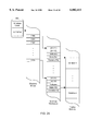
- FIG. 31 illustrates how the Display Refresh List is used to reference video data for display on the display screen during screen refresh
- the CPU 102 typically reads data from system memory 110 across the system bus 106 and then writes the processed data back across the system bus 106 and typically to a local expansion bus to the graphics adapter 112 for display output.
- This action requires that the data make two passes across the system bus 106.
- the program code which manipulates the data must also be read across the system bus 106 from system memory 110. Since the video pixel data that is displayed on the screen is stored in frame buffer memory 114 which is separate from the system memory 110, increased data traffic is required on the system bus 106, thereby reducing system performance. In addition, the requirement of two separate memory subsystems increases the cost of the system.
- the IMC 140 also generates appropriate video signals for driving video display monitor 142.
- the IMC 140 preferably generates red, green, blue (RGB) signals as well as vertical and horizontal synchronization signals for generating images on the video display 142. Therefore, the integrated memory controller 140 of the present invention integrates memory controller and video and graphics controller capabilities into a single logical unit. This greatly reduces bus traffic and increases system performance.
- the IMC 140 also generates appropriate data signals that are provided to Audio DAC 144 for audio presentation. Alternatively, the IMC 140 integrates audio processing capabilities and provides audio signal outputs that are provided directly to speakers.
- a boot device 146 is also coupled to the IMC 140 to configure or boot the IMC 140, as described further below.
- the IMC 140 of the present invention is preferably situated either on the main CPU bus or a high speed system peripheral bus.
- the IMC 140 is coupled directly to the system bus 106 or CPU bus, wherein the IMC 140 interfaces through a cache system 104 to the CPU 102.
- the IMC 140 is situated on the peripheral component interconnect (PCI) bus, which is a high speed peripheral local bus standard developed by Intel Corporation.
- PCI peripheral component interconnect
- the cache 104 preferably comprises a PCI/cache bridge
- the system bus 106 is preferably a PCI bus.
- the IMC 140 can sit on any various types of buses as desired.
- a SCSI (small computer systems interface) adapter 119 is coupled to the PCI bus 118.
- the SCSI adapter connects to two disk drive units 120, a CD-ROM 130, and a tape drive 132.
- Various other devices may be connected to the PCI bus 118, such as a network interface card 134.
- the network interface card 134 interfaces to a local area network (LAN) 136.
- LAN local area network
- bit block transfer This provides the effect of moving data from a source address to a destination address, i.e., a bit block transfer (bit blit), without ever having to move data comprising the object to a new location in system memory 110.
- bit blit bit block transfer
- LAN local area network
- the architecture requires that separate memory control signals be used for each memory bank.
- Memory control signals have independent timing for interleaving of the memory address and memory control signals.
- the present invention includes several modes of address operation to increase speed and performance, all of which are targeted to cause minimal delay in the memory access subsystem.
- the table below lists some of the different methods used for interleaving data on the 128-bit system memory bus.
- Each memory control unit includes the final interface which is specific to the type of system memory being used in the design. Due to the ease of description, this embodiment describes the use of common DRAM memory with enhanced page mode. The preferred embodiment uses a specialty DRAM such as SGRAM or RAMBUS. However, the IMC architecture is not constrained to any specific type of memory.
- FIG. 20 illustrates Mode 0 timing and shows how each of two data buses is interleaved into the IMC 140 on alternating system clocks. Dark arrows depict the data and address flow, while dotted lines indicate possible other paths. Independent addresses are delivered by each memory controller 220 and 222. The data is then brought internal to the IMC 140 and immediately interleaved on the internal 64 bit buses. This doubles the internal data rate from outside the IMC 140 to the internal FIFO's located within the IMC 140. FIG. 20 shows that each memory controller 220 and 222 delivers a different address to each of the two memory banks. The data is then assembled at twice the rate through the cross-bounds data unit. This mode allows for maximum throughput when different memory functions are required for access.
- FIG. 21 illustrates Mode 1 timing and shows how both banks are concatenated such that one address can retrieve 128 bits of data.
- the data and the internal transfer rate stay constant at the memory interface and into the internal FIFO's. Because the memory interface runs at a fixed rate, the data is not multiplexed when in this mode. As an example this mode may be used to fill the internal FIFO's at twice the normal rate from one memory address. Another usage may be to fill the display refresh data FIFO for higher resolution video requirements.
- the IMC 140 includes first and second or foreground and background versions of each register and various of the buffers.
- the term "foreground” is used for the registers and buffers that are for active display to display data on the screen 142 during screen refresh.
- the term “background” is used for the registers and buffers that are used to assemble a new Display Refresh List for a subsequent screen refresh.
- FIG. 24 illustrates the memory organization of system memory 110 as seen by the Window Assembler 240.
- the Window Assembler 240 creates and manipulates various buffers or queues in system memory 110, and these buffers are used by the Window Assembler 240 to access, manipulate and display video data stored in the system memory 110 according to the present invention.
- the system memory 110 includes a Windows ID list, a Windows Workspace buffer, a display memory section for storing video data, and a Display Refresh List.
- the IMC 140 maintains two versions of the Windows ID List memory queue and the Display Refresh List memory queue.
- Driver software executing on the host CPU 102 assembles and/or updates a Windows ID list which includes a pointer for each window or object on the screen.
- the driver software also determines basic information about each window, including information about each window's position, i.e., where each window is to reside on the screen, certain video or attribute information about each window, and the values of pointers to the system memory 110 where the video data for the respective window resides.
- the driver assembles and/or updates a Windows Workspace list or buffer in the system memory 110 through the IMC 140 which includes a windows workspace area comprising this information for each window. The information in each windows workspace area is shown in FIG. 24.
- the IMC 140 For each scan line or span line the IMC 140 reads the foreground Display Refresh List to determine how many windows are present on that line. As shown in FIG. 31, the Xn(Wm) value in the Display Refresh List is used to read the Windows Workspace dynamic pointer which then points to the windows display memory where the pixel data is located. The pixel data is then read for display on the video monitor 142.
- the Display Refresh List also includes information for dynamically adjusting the video data path according to various attributes, including the number of bits per pixel required for the object begin drawn, as well as others.
- the IMC 140 updates the dynamic pointer value to point to the next line for the respective window. This allows the IMC 140 to read the correct display memory for the next line during the refresh. Therefore, when the IMC 140 refreshes the screen, the IMC 140 reads the video data from linear memory and displays the respective XY windows of varying order, wherein the order is determined by the relative placement or depth of the windows relative to each other.
- the IMC 140 includes a Windows Count register and a Window ID List Pointer register.
- the Windows Count register stores the number of windows or objects on the screen.
- the Windows ID List Pointer register includes a value which points to the top of the respective Windows ID list.
- the Windows ID list comprises a list of pointers wherein the list includes a pointer entry for each window or object appearing on the screen.
- the Window Workspace buffer includes a window workspace area for each window or object appearing on the screen.
- the pointers in the Window ID list which each correspond to a respective window, each point to a corresponding window workspace area for that window in the Window Workspace buffer also located in the system memory 110.
- the Windows ID list is preferably order dependent, i.e., all pointers comprised in the Windows ID list have a relative window priority or depth corresponding to the position of the respective pointer in the Windows ID list.
- the first pointer in the list corresponds to the background window or the window at the greatest relative Z-depth
- the last pointer corresponds to the foreground window or the window at the least relative Z-depth.
- the pointers in between the first and last pointer also have a relative window depth priority with respect to their position. It is noted that all windows have a depth priority, and thus a different ID number or pointer in the Windows ID List, even if multiple whole windows appear on the screen at the same time.
- the pointer position within the Windows ID list allows the IMC 140 to determine which windows are on top and which are obscured by other windows.
- the Windows ID list includes two values or entries for each window, one being the address pointer to the respective window workspace area and the other a depth value for a relative position of the window from background to foreground.
- the entries in the Windows ID list are no longer required to be organized in position relative to their respective depth, but rather the depth value stores the relative position of the window. This results in less work for the software video driver when windows are popped or pushed relative to each other, i.e., when the window display or depth priority is changed.
- the Repeat Count value indicates that the same entries should be used in the Display Refresh List for the respective span line as the line before.
- the Repeat Count value minimizes the amount of data contained in the Display Refresh List, and therefore allows for less memory to be used for the Display Refresh List.
- the Repeat Count is incremented.
- the IMC 140 assembles a line which has different parameters or a new object, the new entries are written to the Display Refresh List instead of incrementing the Repeat Count.
- the assembly process is complete when the last Y line and last X position within that line have been processed.
- step 556 If more lines are required to be processed as determined in step 556, then the method returns to step 544 to sort the X values for the next line, pointed to by @nextY. In steps 544-550 the sort of X values is performed on that line to determine respective pointer values that are written into the Display Refresh List as before. This method repeats until the number of lines is complete according to a counter register inside the IMC 140. When all lines have been processed, operation returns to step 542, and method is performed again to assemble a new Display Refresh List when a screen change occurs.
- FIG. 31 illustrates how the Display Refresh List is used to reference video data for display on the display screen during screen refresh.
- the Display Refresh List has been assembled into system memory 110 as described above in FIG. 30.
- the IMC 140 includes foreground and background display refresh pointer registers each storing a display refresh pointer which points to the top of the respective Display Refresh List.
- An assembled Display Refresh List includes a plurality of entries which indicate how video data is to be presented on the screen during screen refresh. Each entry includes the X start address of the window, the pitch count or width of the window on the span line, and possibly a binary field which references a microcode instruction for dynamic configuration of the Refresh logic 404 depending on the object being drawn.
- the IMC 140 copies the static address pointers into the dynamic address pointers.
- the IMC 140 then reads the first value of the Display Refresh List.
- This value includes an X start address, a pitch count value, and possible a binary field referencing a microcode instruction or opcode for the various attributes of the object or window.
- the microcode instruction is preferably configured during an Assemble Display Refresh command and is executed here to configure the IMC 140 for the correct number of bits per pixel, alpha blending, and other attributes for the object or window being rendered.
- the Display Refresh List value also contains the address pointer to the dynamic address pointers within the windows workspace area.
- the Refresh Unit 404 reads the entries in the Display Refresh List for the next span line. As noted above, the Refresh Unit 404 examines these entries to determine where windows or objects begin and end on the respective span line. The next entry in the Display Refresh List corresponds to drawing window W0 on the second span line. This second entry does not reference a microcode instruction for reconfiguration of the Refresh Unit 404 since the same window is being drawn as before.
- the X start address indicates that the video data should start at x0, and the pitch count value indicates that the video data for window W0 occupies the entire span line.
- the pointer value in this entry references the dynamic pointer in the window workspace area of window W0, which in turn references the video data for the second span line of window W0.
- the video data is obtained from system memory 110 and converted to analog video signals for display as described above.
- the X start address indicates that the video data should begin at x4, and the pitch count in this entry indicates that the video data for window W2 should occupy the next 9 pixels, or up to x12.
- the pointer value in this entry references the dynamic pointer in the window workspace area of window W2, which in turn references the video data for the top of window W2.
- the video data for window W2 is obtained from system memory 110 and converted to analog video signals for display as described above.
- the IMC 140 switches the foreground and background registers and buffers such that the next active line is read indirectly with use of the new foreground Display Refresh List.
- This same technique is used for position changes and depth adjustments.
- the modification is made in the background Windows ID list or background Windows Workspace area.
- the switch between background and foreground registers and buffers occurs. As part of this switch, the address at the top of Window ID list is programmed into the IMC's background Window ID list pointer.
- the present invention further includes a novel method for assembling 2D and 3D objects.
- the update of the Display Refresh List is performed continuously with slopes on the bounds of the object.
- execution of the Display Refresh List renders triangles of texture without moving the texture maps.
Abstract
Description
______________________________________
Mode 0:
      Interleaved access
                    Used for system transfers during
      to/from different
                    display refresh operation. Also used
      address spaces.
                    for compression/decompression to
                    achieve high rate. Also used for
                    raster operations which modify
                    source data.
Mode 1:
      Interleaved access
                    Used for high resolution display
      to/from a single
                    refresh or system transfers when
      sequential address.
                    only a single memory address is
                    required.
Mode 2:
      Non-Interleaved access
                    Used for access of data from the
      to a single sequential
                    same physical bank of memory.
      address.
______________________________________
Claims (26)
Priority Applications (12)
| Application Number | Priority Date | Filing Date | Title |
|---|---|---|---|
| US08/340,667 US6002411A (en) | 1994-11-16 | 1994-11-16 | Integrated video and memory controller with data processing and graphical processing capabilities |
| US08/565,103 US5838334A (en) | 1994-11-16 | 1995-11-30 | Memory and graphics controller which performs pointer-based display list video refresh operations |
| US08/604,670 US5995120A (en) | 1994-11-16 | 1996-02-21 | Graphics system including a virtual frame buffer which stores video/pixel data in a plurality of memory areas |
| US08/770,017 US6108014A (en) | 1994-11-16 | 1996-12-19 | System and method for simultaneously displaying a plurality of video data objects having a different bit per pixel formats |
| US08/916,464 US6173381B1 (en) | 1994-11-16 | 1997-08-08 | Memory controller including embedded data compression and decompression engines |
| US09/056,021 US6067098A (en) | 1994-11-16 | 1998-04-06 | Video/graphics controller which performs pointer-based display list video refresh operation |
| US09/239,659 US7190284B1 (en) | 1994-11-16 | 1999-01-29 | Selective lossless, lossy, or no compression of data based on address range, data type, and/or requesting agent |
| US09/241,139 US6370631B1 (en) | 1994-11-16 | 1999-02-01 | Memory controller including compression/decompression capabilities for improved data access |
| US09/461,172 US6170047B1 (en) | 1994-11-16 | 1999-12-14 | System and method for managing system memory and/or non-volatile memory using a memory controller with integrated compression and decompression capabilities |
| US09/963,090 US20020010819A1 (en) | 1994-11-16 | 2001-09-25 | Memory controller including a hardware compression and decompression engine for managing system memory |
| US12/353,907 US8176288B2 (en) | 1994-11-16 | 2009-01-14 | Memory controller including a hardware compression and decompression engine for managing system memory and graphical operations |
| US13/465,838 US8711164B2 (en) | 1994-11-16 | 2012-05-07 | Memory controller including a hardware compression and decompression engine for managing system memory and graphical operations |
Applications Claiming Priority (1)
| Application Number | Priority Date | Filing Date | Title |
|---|---|---|---|
| US08/340,667 US6002411A (en) | 1994-11-16 | 1994-11-16 | Integrated video and memory controller with data processing and graphical processing capabilities |
Related Child Applications (4)
| Application Number | Title | Priority Date | Filing Date |
|---|---|---|---|
| US46310695A Division | 1994-11-16 | 1995-06-05 | |
| US46310695A Continuation-In-Part | 1994-11-16 | 1995-06-05 | |
| US52212995A Continuation-In-Part | 1994-11-16 | 1995-08-31 | |
| US08/565,103 Continuation-In-Part US5838334A (en) | 1994-11-16 | 1995-11-30 | Memory and graphics controller which performs pointer-based display list video refresh operations |
Publications (1)
| Publication Number | Publication Date |
|---|---|
| US6002411A true US6002411A (en) | 1999-12-14 |
Family
ID=23334432
Family Applications (6)
| Application Number | Title | Priority Date | Filing Date |
|---|---|---|---|
| US08/340,667 Expired - Lifetime US6002411A (en) | 1994-11-16 | 1994-11-16 | Integrated video and memory controller with data processing and graphical processing capabilities |
| US08/916,464 Expired - Lifetime US6173381B1 (en) | 1994-11-16 | 1997-08-08 | Memory controller including embedded data compression and decompression engines |
| US09/241,139 Expired - Lifetime US6370631B1 (en) | 1994-11-16 | 1999-02-01 | Memory controller including compression/decompression capabilities for improved data access |
| US09/963,090 Abandoned US20020010819A1 (en) | 1994-11-16 | 2001-09-25 | Memory controller including a hardware compression and decompression engine for managing system memory |
| US12/353,907 Expired - Fee Related US8176288B2 (en) | 1994-11-16 | 2009-01-14 | Memory controller including a hardware compression and decompression engine for managing system memory and graphical operations |
| US13/465,838 Expired - Fee Related US8711164B2 (en) | 1994-11-16 | 2012-05-07 | Memory controller including a hardware compression and decompression engine for managing system memory and graphical operations |
Family Applications After (5)
| Application Number | Title | Priority Date | Filing Date |
|---|---|---|---|
| US08/916,464 Expired - Lifetime US6173381B1 (en) | 1994-11-16 | 1997-08-08 | Memory controller including embedded data compression and decompression engines |
| US09/241,139 Expired - Lifetime US6370631B1 (en) | 1994-11-16 | 1999-02-01 | Memory controller including compression/decompression capabilities for improved data access |
| US09/963,090 Abandoned US20020010819A1 (en) | 1994-11-16 | 2001-09-25 | Memory controller including a hardware compression and decompression engine for managing system memory |
| US12/353,907 Expired - Fee Related US8176288B2 (en) | 1994-11-16 | 2009-01-14 | Memory controller including a hardware compression and decompression engine for managing system memory and graphical operations |
| US13/465,838 Expired - Fee Related US8711164B2 (en) | 1994-11-16 | 2012-05-07 | Memory controller including a hardware compression and decompression engine for managing system memory and graphical operations |
Country Status (1)
| Country | Link |
|---|---|
| US (6) | US6002411A (en) |
Cited By (100)
| Publication number | Priority date | Publication date | Assignee | Title |
|---|---|---|---|---|
| US6157743A (en) * | 1998-07-31 | 2000-12-05 | Hewlett Packard Company | Method for retrieving compressed texture data from a memory system |
| US6170047B1 (en) | 1994-11-16 | 2001-01-02 | Interactive Silicon, Inc. | System and method for managing system memory and/or non-volatile memory using a memory controller with integrated compression and decompression capabilities |
| US6208273B1 (en) | 1999-01-29 | 2001-03-27 | Interactive Silicon, Inc. | System and method for performing scalable embedded parallel data compression |
| US6222564B1 (en) * | 1995-08-17 | 2001-04-24 | Intel Corporation | Method and apparatus for managing access to a computer system memory shared by a graphics controller and a memory controller |
| US6243081B1 (en) * | 1998-07-31 | 2001-06-05 | Hewlett-Packard Company | Data structure for efficient retrieval of compressed texture data from a memory system |
| WO2001080016A2 (en) * | 2000-04-14 | 2001-10-25 | Interactive Silicon, Inc. | Parallel compression/decompression system and method for implementation of in-memory compressed cache |
| US20010038642A1 (en) * | 1999-01-29 | 2001-11-08 | Interactive Silicon, Inc. | System and method for performing scalable embedded parallel data decompression |
| US6333745B1 (en) * | 1996-09-30 | 2001-12-25 | Hitachi, Ltd. | Data processor having unified memory architecture providing priority memory access |
| US20020010819A1 (en) * | 1994-11-16 | 2002-01-24 | Interactive Silicon, Inc. | Memory controller including a hardware compression and decompression engine for managing system memory |
| US20020101367A1 (en) * | 1999-01-29 | 2002-08-01 | Interactive Silicon, Inc. | System and method for generating optimally compressed data from a plurality of data compression/decompression engines implementing different data compression algorithms |
| US20020101452A1 (en) * | 1997-11-21 | 2002-08-01 | Xside Corporation | Secondary user interface |
| US6453393B1 (en) * | 2000-09-18 | 2002-09-17 | Intel Corporation | Method and apparatus for interfacing to a computer memory |
| US20020149593A1 (en) * | 1997-11-21 | 2002-10-17 | Xsides Corporation | Method and system for displaying data in a second display area |
| US20030001848A1 (en) * | 2001-06-29 | 2003-01-02 | Doyle Peter L. | Apparatus, method and system with a graphics-rendering engine having a graphics context manager |
| US20030033051A1 (en) * | 2001-08-09 | 2003-02-13 | John Wilkes | Self-disentangling data storage technique |
| US6522327B2 (en) * | 1995-08-04 | 2003-02-18 | Sun Microsystems, Inc. | Decompression of variable-length encoded compressed three-dimensional graphics data |
| US6529935B1 (en) | 1998-11-09 | 2003-03-04 | Broadcom Corporation | Graphics display system with unified memory architecture |
| EP1288891A1 (en) * | 2001-08-27 | 2003-03-05 | Hewlett-Packard Company | Process and apparatus for displaying data in a specific area of the display in a computer or in an interactive terminal under control of the LAN card and independently on the operating system |
| US6538656B1 (en) | 1999-11-09 | 2003-03-25 | Broadcom Corporation | Video and graphics system with a data transport processor |
| US20030061457A1 (en) * | 2000-04-14 | 2003-03-27 | Interactive Silicon, Incorporated | Managing a codec engine for memory compression / decompression operations using a data movement engine |
| US6542162B1 (en) * | 1998-06-15 | 2003-04-01 | International Business Machines Corporation | Color mapped and direct color OSD region processor with support for 4:2:2 profile decode function |
| US20030067469A1 (en) * | 2001-10-09 | 2003-04-10 | Atousa Soroushi | Inklayer image with transparency |
| US6573905B1 (en) | 1999-11-09 | 2003-06-03 | Broadcom Corporation | Video and graphics system with parallel processing of graphics windows |
| US20030126370A1 (en) * | 2002-01-03 | 2003-07-03 | Lienhart Rainer W. | Method and apparatus for cache management |
| US6590592B1 (en) | 1999-04-23 | 2003-07-08 | Xsides Corporation | Parallel interface |
| US6593945B1 (en) | 1999-05-21 | 2003-07-15 | Xsides Corporation | Parallel graphical user interface |
| US6601104B1 (en) | 1999-03-11 | 2003-07-29 | Realtime Data Llc | System and methods for accelerated data storage and retrieval |
| US6604158B1 (en) | 1999-03-11 | 2003-08-05 | Realtime Data, Llc | System and methods for accelerated data storage and retrieval |
| US6630943B1 (en) | 1999-09-21 | 2003-10-07 | Xsides Corporation | Method and system for controlling a complementary user interface on a display surface |
| US6636222B1 (en) | 1999-11-09 | 2003-10-21 | Broadcom Corporation | Video and graphics system with an MPEG video decoder for concurrent multi-row decoding |
| US6639613B1 (en) * | 1997-11-21 | 2003-10-28 | Xsides Corporation | Alternate display content controller |
| US6661422B1 (en) | 1998-11-09 | 2003-12-09 | Broadcom Corporation | Video and graphics system with MPEG specific data transfer commands |
| US6678007B2 (en) | 1997-11-21 | 2004-01-13 | Xsides Corporation | Alternate display content controller |
| US6686936B1 (en) | 1997-11-21 | 2004-02-03 | Xsides Corporation | Alternate display content controller |
| US6717582B2 (en) | 1997-12-30 | 2004-04-06 | Micron Technology, Inc. | Accelerated graphics port for a multiple memory controller computer system |
| US6717596B1 (en) | 2000-02-18 | 2004-04-06 | Xsides Corporation | Method and system for controlling a complementary user interface on a display surface |
| US6741254B1 (en) | 1997-12-30 | 2004-05-25 | Micron Technology, Inc. | Method of implementing an accelerated graphics port for a multiple memory controller computer system |
| US6768774B1 (en) | 1998-11-09 | 2004-07-27 | Broadcom Corporation | Video and graphics system with video scaling |
| US20040160448A1 (en) * | 1997-12-30 | 2004-08-19 | Joseph Jeddeloh | Accelerated graphics port for a multiple memory controller computer system |
| US6781601B2 (en) | 1999-11-09 | 2004-08-24 | Broadcom Corporation | Transport processor |
| US20040215852A1 (en) * | 2003-04-25 | 2004-10-28 | Klein Dean A. | Active memory data compression system and method |
| US20040226041A1 (en) * | 2000-02-18 | 2004-11-11 | Xsides Corporation | System and method for parallel data display of multiple executing environments |
| US6819271B2 (en) | 1999-01-29 | 2004-11-16 | Quickshift, Inc. | Parallel compression and decompression system and method having multiple parallel compression and decompression engines |
| US6822589B1 (en) | 1999-01-29 | 2004-11-23 | Quickshift, Inc. | System and method for performing scalable embedded parallel data decompression |
| US20050018910A1 (en) * | 2003-07-23 | 2005-01-27 | Eric Jeffrey | Method and apparatus for reducing the bandwidth required to transmit image data |
| US6879266B1 (en) | 1997-08-08 | 2005-04-12 | Quickshift, Inc. | Memory module including scalable embedded parallel data compression and decompression engines |
| US20050104753A1 (en) * | 2003-11-18 | 2005-05-19 | M-Systems Flash Disk Pioneers, Ltd. | Decompression accelerator for flash memory |
| US20050146530A1 (en) * | 2003-12-31 | 2005-07-07 | Zerphy Bryron L. | System and method for rapidly refreshing a dynamic message sign display panel |
| US6943801B2 (en) * | 2000-03-31 | 2005-09-13 | Scott A. Rosenberg | System and method for refreshing imaging devices or displays on a page-level basis |
| US20050286775A1 (en) * | 2004-06-25 | 2005-12-29 | Eric Jeffrey | Method and apparatus for storing image data using an MCU buffer |
| US20060023952A1 (en) * | 2004-07-29 | 2006-02-02 | Rai Barinder S | Method and apparatus for transforming the dimensions of an image |
| US20060044293A1 (en) * | 2004-08-20 | 2006-03-02 | Dialog Semiconductor Gmbh | Display controller with DRAM graphic memory |
| US7058177B1 (en) | 2000-11-28 | 2006-06-06 | Xilinx, Inc. | Partially encrypted bitstream method |
| US7106347B1 (en) * | 2000-05-31 | 2006-09-12 | Intel Corporation | Transforming pixel data and addresses |
| US7190284B1 (en) | 1994-11-16 | 2007-03-13 | Dye Thomas A | Selective lossless, lossy, or no compression of data based on address range, data type, and/or requesting agent |
| US20070097140A1 (en) * | 2005-10-28 | 2007-05-03 | Fenney Simon J | Full screen anti-aliasing with dynamic filters |
| US20070120874A1 (en) * | 2003-04-25 | 2007-05-31 | Macinnis Alexander G | Graphics display system with line buffer control scheme |
| US20070241988A1 (en) * | 2003-12-31 | 2007-10-18 | Zerphy Byron L | Dynamic message sign display panel error detection, correction, and notification |
| US20070248288A1 (en) * | 2006-04-20 | 2007-10-25 | Fuji Xerox Co., Ltd. | Image processing device, and recording medium |
| US20070247466A1 (en) * | 2006-04-20 | 2007-10-25 | Fuji Xerox Co., Ltd | Image processing apparatus and program |
| US20080001953A1 (en) * | 2006-06-29 | 2008-01-03 | Fuji Xerox Co., Ltd. | Image processing device and method and storage medium storing program |
| US20080013862A1 (en) * | 2006-07-14 | 2008-01-17 | Fuji Xerox Co., Ltd. | Image processing apparatus, storage medium in which image processing program is stored, and image processing method |
| US20080022028A1 (en) * | 2006-07-18 | 2008-01-24 | Liantec Systems Corporation. | Interface card and a computer motherboard which are used in a horizontal adaptation |
| US20090002385A1 (en) * | 2005-12-27 | 2009-01-01 | Imsys Technologies Ab | Method and System for Cost-Efficient, High-Resolution Graphics/Image Display System |
| US7538694B2 (en) | 1999-01-29 | 2009-05-26 | Mossman Holdings Llc | Network device with improved storage density and access speed using compression techniques |
| US20090313398A1 (en) * | 2002-08-08 | 2009-12-17 | International Business Machines Corporation | Method and system for storing memory compressed data onto memory compressed disks |
| US20100026696A1 (en) * | 2008-07-31 | 2010-02-04 | Kabushiki Kaisha Toshiba | Image data processing method, image data processor, and data structure |
| US7659900B2 (en) | 1998-11-09 | 2010-02-09 | Broadcom Corporation | Video and graphics system with parallel processing of graphics windows |
| US7667715B2 (en) | 1999-11-09 | 2010-02-23 | Broadcom Corporation | Video, audio and graphics decode, composite and display system |
| US7714747B2 (en) | 1998-12-11 | 2010-05-11 | Realtime Data Llc | Data compression systems and methods |
| US7777651B2 (en) | 2000-10-03 | 2010-08-17 | Realtime Data Llc | System and method for data feed acceleration and encryption |
| US20110025917A1 (en) * | 2009-07-29 | 2011-02-03 | Yamaha Corporation | Video processing device |
| US20110063304A1 (en) * | 2009-09-16 | 2011-03-17 | Nvidia Corporation | Co-processing synchronizing techniques on heterogeneous graphics processing units |
| US20110145520A1 (en) * | 2009-12-16 | 2011-06-16 | Electronics And Telecommunications Research Institute | Audio signal processing apparatus and method, and communication terminal apparatus |
| US20110179191A1 (en) * | 2010-01-21 | 2011-07-21 | Beni Imanilov | Remote CPU-Less Decompression |
| US20110202150A1 (en) * | 2009-10-16 | 2011-08-18 | Newport Controls | Controller system adapted for SPA |
| US8054879B2 (en) | 2001-02-13 | 2011-11-08 | Realtime Data Llc | Bandwidth sensitive data compression and decompression |
| US8063916B2 (en) | 2003-10-22 | 2011-11-22 | Broadcom Corporation | Graphics layer reduction for video composition |
| US8090936B2 (en) | 2000-02-03 | 2012-01-03 | Realtime Data, Llc | Systems and methods for accelerated loading of operating systems and application programs |
| US8199154B2 (en) | 1998-11-09 | 2012-06-12 | Broadcom Corporation | Low resolution graphics mode support using window descriptors |
| US20120147023A1 (en) * | 2010-12-14 | 2012-06-14 | Electronics And Telecommunications Research Institute | Caching apparatus and method for video motion estimation and compensation |
| US8243086B1 (en) * | 2007-12-13 | 2012-08-14 | Nvidia Corporation | Variable length data compression using a geometry shading unit |
| US8254701B1 (en) | 2007-12-13 | 2012-08-28 | Nvidia Corporation | Data compression using a geometry shading unit |
| US8295621B1 (en) | 2007-12-13 | 2012-10-23 | Nvidia Corporation | Data decompression using a geometry shading unit |
| US20120320067A1 (en) * | 2011-06-17 | 2012-12-20 | Konstantine Iourcha | Real time on-chip texture decompression using shader processors |
| US8587600B1 (en) * | 2005-05-02 | 2013-11-19 | Advanced Micro Devices, Inc. | System and method for cache-based compressed display data storage |
| US8692695B2 (en) | 2000-10-03 | 2014-04-08 | Realtime Data, Llc | Methods for encoding and decoding data |
| US20140317149A1 (en) * | 2013-04-22 | 2014-10-23 | Sap Ag | Multi-Buffering System Supporting Read/Write Access to Different Data Source Type |
| US8913667B2 (en) | 1999-11-09 | 2014-12-16 | Broadcom Corporation | Video decoding system having a programmable variable-length decoder |
| US20150138229A1 (en) * | 2013-11-15 | 2015-05-21 | Ncomputing Inc. | Systems and methods for compositing a display image from display planes using enhanced bit-level block transfer hardware |
| US20150176846A1 (en) * | 2012-07-16 | 2015-06-25 | Rational Aktiengesellschaft | Method for Displaying Parameters of a Cooking Process and Display Device for a Cooking Appliance |
| US9075559B2 (en) | 2009-02-27 | 2015-07-07 | Nvidia Corporation | Multiple graphics processing unit system and method |
| US9135675B2 (en) | 2009-06-15 | 2015-09-15 | Nvidia Corporation | Multiple graphics processing unit display synchronization system and method |
| US9143546B2 (en) | 2000-10-03 | 2015-09-22 | Realtime Data Llc | System and method for data feed acceleration and encryption |
| US20160080457A1 (en) * | 2009-06-01 | 2016-03-17 | Sony Computer Entertainment America Llc | Qualified Video Delivery Methods |
| US9449585B2 (en) | 2013-11-15 | 2016-09-20 | Ncomputing, Inc. | Systems and methods for compositing a display image from display planes using enhanced blending hardware |
| US9818379B2 (en) | 2013-08-08 | 2017-11-14 | Nvidia Corporation | Pixel data transmission over multiple pixel interfaces |
| CN107870878A (en) * | 2017-10-31 | 2018-04-03 | 深圳清华大学研究院 | Storage system, terminal and computer installation |
| US20190291003A1 (en) * | 2009-06-01 | 2019-09-26 | Sony Interactive Entertainment America Llc | Qualified Video Delivery Methods |
| CN116841920A (en) * | 2017-07-28 | 2023-10-03 | 苹果公司 | System and method for performing memory compression |
Families Citing this family (202)
| Publication number | Priority date | Publication date | Assignee | Title |
|---|---|---|---|---|
| US6118462A (en) | 1997-07-01 | 2000-09-12 | Memtrax Llc | Computer system controller having internal memory and external memory control |
| US6954804B2 (en) * | 1998-03-26 | 2005-10-11 | Micro, Inc. | Controller for portable electronic devices |
| US6895448B2 (en) * | 1998-03-26 | 2005-05-17 | O2 Micro, Inc. | Low-power audio CD player for portable computers |
| US6675233B1 (en) | 1998-03-26 | 2004-01-06 | O2 Micro International Limited | Audio controller for portable electronic devices |
| US6353871B1 (en) | 1999-02-22 | 2002-03-05 | International Business Machines Corporation | Directory cache for indirectly addressed main memory |
| US6449679B2 (en) * | 1999-02-26 | 2002-09-10 | Micron Technology, Inc. | RAM controller interface device for RAM compatibility (memory translator hub) |
| US6349372B1 (en) | 1999-05-19 | 2002-02-19 | International Business Machines Corporation | Virtual uncompressed cache for compressed main memory |
| GB2355161B (en) * | 1999-10-05 | 2001-09-12 | 3Com Corp | Network device incorporating selective compression of stored data packets |
| AU2018201A (en) * | 1999-10-12 | 2001-04-23 | Perception Digital Technology (Bvi) Limited | Digital multimedia jukebox |
| JP2001134486A (en) * | 1999-11-04 | 2001-05-18 | Fujitsu Ltd | Microprocessor and storage device |
| US7330916B1 (en) * | 1999-12-02 | 2008-02-12 | Nvidia Corporation | Graphic controller to manage a memory and effective size of FIFO buffer as viewed by CPU can be as large as the memory |
| US6567911B1 (en) * | 1999-12-06 | 2003-05-20 | Adaptec, Inc. | Method of conserving memory resources during execution of system BIOS |
| US6452602B1 (en) * | 1999-12-13 | 2002-09-17 | Ati International Srl | Method and apparatus for storing compressed data |
| US20030191876A1 (en) * | 2000-02-03 | 2003-10-09 | Fallon James J. | Data storewidth accelerator |
| US7130930B1 (en) * | 2000-06-16 | 2006-10-31 | O2 Micro Inc. | Low power CD-ROM player with CD-ROM subsystem for portable computer capable of playing audio CDs without supply energy to CPU |
| US6636939B1 (en) * | 2000-06-29 | 2003-10-21 | Intel Corporation | Method and apparatus for processor bypass path to system memory |
| US6643744B1 (en) | 2000-08-23 | 2003-11-04 | Nintendo Co., Ltd. | Method and apparatus for pre-fetching audio data |
| US6606689B1 (en) | 2000-08-23 | 2003-08-12 | Nintendo Co., Ltd. | Method and apparatus for pre-caching data in audio memory |
| US6883079B1 (en) * | 2000-09-01 | 2005-04-19 | Maxtor Corporation | Method and apparatus for using data compression as a means of increasing buffer bandwidth |
| US6564305B1 (en) * | 2000-09-20 | 2003-05-13 | Hewlett-Packard Development Company Lp | Compressing memory management in a device |
| US6779088B1 (en) | 2000-10-24 | 2004-08-17 | International Business Machines Corporation | Virtual uncompressed cache size control in compressed memory systems |
| US7047382B2 (en) * | 2000-11-29 | 2006-05-16 | Quickshift, Inc. | System and method for managing compression and decompression and decompression of system memory in a computer system |
| US7522965B2 (en) * | 2000-12-01 | 2009-04-21 | O2Micro International Limited | Low power digital audio decoding/playing system for computing devices |
| US7522964B2 (en) * | 2000-12-01 | 2009-04-21 | O2Micro International Limited | Low power digital audio decoding/playing system for computing devices |
| US7526349B2 (en) * | 2000-12-01 | 2009-04-28 | O2Micro International Limited | Low power digital audio decoding/playing system for computing devices |
| US7818443B2 (en) * | 2000-12-01 | 2010-10-19 | O2Micro International Ltd. | Low power digital audio decoding/playing system for computing devices |
| US7890741B2 (en) * | 2000-12-01 | 2011-02-15 | O2Micro International Limited | Low power digital audio decoding/playing system for computing devices |
| US7522966B2 (en) * | 2000-12-01 | 2009-04-21 | O2Micro International Limited | Low power digital audio decoding/playing system for computing devices |
| US6615334B2 (en) * | 2000-12-27 | 2003-09-02 | International Business Machines Corporation | Method and apparatus for I/O data management with an I/O buffer in compressed memory subsystem |
| US6647456B1 (en) * | 2001-02-23 | 2003-11-11 | Nvidia Corporation | High bandwidth-low latency memory controller |
| JP2002264442A (en) * | 2001-03-12 | 2002-09-18 | Ricoh Co Ltd | Image processor |
| US7032158B2 (en) * | 2001-04-23 | 2006-04-18 | Quickshift, Inc. | System and method for recognizing and configuring devices embedded on memory modules |
| US6892246B2 (en) * | 2001-06-13 | 2005-05-10 | Alan N. Cooper | Computer system and method for storing video data |
| US7035965B2 (en) | 2001-08-30 | 2006-04-25 | Micron Technology, Inc. | Flash memory with data decompression |
| JP3900467B2 (en) * | 2001-11-05 | 2007-04-04 | インターナショナル・ビジネス・マシーンズ・コーポレーション | EXTERNAL STORAGE DEVICE, EXTERNAL STORAGE DEVICE CONTROL METHOD, PROGRAM, AND RECORDING MEDIUM |
| EP1308695A1 (en) * | 2001-11-06 | 2003-05-07 | Matsushita Electric Industrial Co., Ltd. | Vehicle mounted display system |
| US6640283B2 (en) * | 2002-01-16 | 2003-10-28 | Hewlett-Packard Development Company, L.P. | Apparatus for cache compression engine for data compression of on-chip caches to increase effective cache size |
| US6795897B2 (en) * | 2002-05-15 | 2004-09-21 | International Business Machines Corporation | Selective memory controller access path for directory caching |
| US6857047B2 (en) * | 2002-06-10 | 2005-02-15 | Hewlett-Packard Development Company, L.P. | Memory compression for computer systems |
| US6829691B2 (en) * | 2002-06-28 | 2004-12-07 | Hewlett-Packard Development, L.P. | System for compressing/decompressing data |
| US7526595B2 (en) * | 2002-07-25 | 2009-04-28 | International Business Machines Corporation | Data path master/slave data processing device apparatus and method |
| US6981119B1 (en) | 2002-08-29 | 2005-12-27 | Advanced Micro Devices, Inc. | System and method for storing performance-enhancing data in memory space freed by data compression |
| US6795880B2 (en) * | 2002-11-05 | 2004-09-21 | Sbc Technology Resources, Inc. | System and method for processing high speed data |
| US20060271761A1 (en) * | 2003-04-16 | 2006-11-30 | Riemens Abraham K | Data processing apparatus that uses compression or data stored in memory |
| GB2403033A (en) * | 2003-06-18 | 2004-12-22 | Research In Motion Ltd | PDA software compression |
| US7636810B2 (en) * | 2003-11-26 | 2009-12-22 | Intel Corporation | Method, system, and apparatus for memory compression with flexible in-memory cache |
| US7302543B2 (en) * | 2004-06-16 | 2007-11-27 | Nec Laboratories America, Inc. | Compressed memory architecture for embedded systems |
| US20050289288A1 (en) * | 2004-06-25 | 2005-12-29 | Matheny David L | Compression and decompression of expansion read only memories |
| US7539800B2 (en) * | 2004-07-30 | 2009-05-26 | International Business Machines Corporation | System, method and storage medium for providing segment level sparing |
| US7389375B2 (en) * | 2004-07-30 | 2008-06-17 | International Business Machines Corporation | System, method and storage medium for a multi-mode memory buffer device |
| US7224595B2 (en) | 2004-07-30 | 2007-05-29 | International Business Machines Corporation | 276-Pin buffered memory module with enhanced fault tolerance |
| US20060036826A1 (en) * | 2004-07-30 | 2006-02-16 | International Business Machines Corporation | System, method and storage medium for providing a bus speed multiplier |
| US7296129B2 (en) * | 2004-07-30 | 2007-11-13 | International Business Machines Corporation | System, method and storage medium for providing a serialized memory interface with a bus repeater |
| US7711856B1 (en) * | 2004-09-30 | 2010-05-04 | Avaya Inc. | Method and apparatus for providing an interface for a messaging mailbox |
| US20060085562A1 (en) * | 2004-10-14 | 2006-04-20 | Blaho Bruce E | Devices and methods for remote computing using a network processor |
| US7331010B2 (en) | 2004-10-29 | 2008-02-12 | International Business Machines Corporation | System, method and storage medium for providing fault detection and correction in a memory subsystem |
| US7299313B2 (en) * | 2004-10-29 | 2007-11-20 | International Business Machines Corporation | System, method and storage medium for a memory subsystem command interface |
| US7512762B2 (en) * | 2004-10-29 | 2009-03-31 | International Business Machines Corporation | System, method and storage medium for a memory subsystem with positional read data latency |
| US7395476B2 (en) | 2004-10-29 | 2008-07-01 | International Business Machines Corporation | System, method and storage medium for providing a high speed test interface to a memory subsystem |
| US7305574B2 (en) * | 2004-10-29 | 2007-12-04 | International Business Machines Corporation | System, method and storage medium for bus calibration in a memory subsystem |
| US7441060B2 (en) * | 2004-10-29 | 2008-10-21 | International Business Machines Corporation | System, method and storage medium for providing a service interface to a memory system |
| US7356737B2 (en) | 2004-10-29 | 2008-04-08 | International Business Machines Corporation | System, method and storage medium for testing a memory module |
| US7277988B2 (en) | 2004-10-29 | 2007-10-02 | International Business Machines Corporation | System, method and storage medium for providing data caching and data compression in a memory subsystem |
| US8356127B2 (en) * | 2004-12-09 | 2013-01-15 | Rambus Inc. | Memory interface with workload adaptive encode/decode |
| US20060188151A1 (en) * | 2005-02-23 | 2006-08-24 | Lexmark International, Inc. | Method for processing data for use with a video display of an imaging apparatus |
| US20060253749A1 (en) * | 2005-05-09 | 2006-11-09 | International Business Machines Corporation | Real-time memory verification in a high-availability system |
| US8473673B2 (en) * | 2005-06-24 | 2013-06-25 | Hewlett-Packard Development Company, L.P. | Memory controller based (DE)compression |
| US20070005625A1 (en) * | 2005-07-01 | 2007-01-04 | Nec Laboratories America, Inc. | Storage architecture for embedded systems |
| US7880738B2 (en) * | 2005-07-14 | 2011-02-01 | Molsoft Llc | Structured documents and systems, methods and computer programs for creating, producing and displaying three dimensional objects and other related information in those structured documents |
| US7995065B2 (en) * | 2005-09-23 | 2011-08-09 | Samsung Electronics Co., Ltd. | Animation reproducing apparatus and method |
| US7478259B2 (en) * | 2005-10-31 | 2009-01-13 | International Business Machines Corporation | System, method and storage medium for deriving clocks in a memory system |
| US7516291B2 (en) * | 2005-11-21 | 2009-04-07 | Red Hat, Inc. | Cooperative mechanism for efficient application memory allocation |
| US7685392B2 (en) | 2005-11-28 | 2010-03-23 | International Business Machines Corporation | Providing indeterminate read data latency in a memory system |
| US7636813B2 (en) | 2006-05-22 | 2009-12-22 | International Business Machines Corporation | Systems and methods for providing remote pre-fetch buffers |
| US7640386B2 (en) * | 2006-05-24 | 2009-12-29 | International Business Machines Corporation | Systems and methods for providing memory modules with multiple hub devices |
| US7594055B2 (en) * | 2006-05-24 | 2009-09-22 | International Business Machines Corporation | Systems and methods for providing distributed technology independent memory controllers |
| US8769311B2 (en) | 2006-05-31 | 2014-07-01 | International Business Machines Corporation | Systems and methods for transformation of logical data objects for storage |
| WO2007138602A2 (en) | 2006-05-31 | 2007-12-06 | Storwize Ltd. | Method and system for transformation of logical data objects for storage |
| US7584336B2 (en) | 2006-06-08 | 2009-09-01 | International Business Machines Corporation | Systems and methods for providing data modification operations in memory subsystems |
| US7391345B2 (en) * | 2006-06-29 | 2008-06-24 | Intel Corporation | Storing compressed code on a non-volatile memory |
| US7493439B2 (en) * | 2006-08-01 | 2009-02-17 | International Business Machines Corporation | Systems and methods for providing performance monitoring in a memory system |
| US7669086B2 (en) * | 2006-08-02 | 2010-02-23 | International Business Machines Corporation | Systems and methods for providing collision detection in a memory system |
| US7581073B2 (en) | 2006-08-09 | 2009-08-25 | International Business Machines Corporation | Systems and methods for providing distributed autonomous power management in a memory system |
| US7587559B2 (en) * | 2006-08-10 | 2009-09-08 | International Business Machines Corporation | Systems and methods for memory module power management |
| US7490217B2 (en) | 2006-08-15 | 2009-02-10 | International Business Machines Corporation | Design structure for selecting memory busses according to physical memory organization information stored in virtual address translation tables |
| US7539842B2 (en) | 2006-08-15 | 2009-05-26 | International Business Machines Corporation | Computer memory system for selecting memory buses according to physical memory organization information stored in virtual address translation tables |
| US7477522B2 (en) * | 2006-10-23 | 2009-01-13 | International Business Machines Corporation | High density high reliability memory module with a fault tolerant address and command bus |
| US7870459B2 (en) * | 2006-10-23 | 2011-01-11 | International Business Machines Corporation | High density high reliability memory module with power gating and a fault tolerant address and command bus |
| US8443134B2 (en) * | 2006-12-06 | 2013-05-14 | Fusion-Io, Inc. | Apparatus, system, and method for graceful cache device degradation |
| US8489817B2 (en) | 2007-12-06 | 2013-07-16 | Fusion-Io, Inc. | Apparatus, system, and method for caching data |
| US7713068B2 (en) | 2006-12-06 | 2010-05-11 | Fusion Multisystems, Inc. | Apparatus, system, and method for a scalable, composite, reconfigurable backplane |
| US8074011B2 (en) * | 2006-12-06 | 2011-12-06 | Fusion-Io, Inc. | Apparatus, system, and method for storage space recovery after reaching a read count limit |
| US9104599B2 (en) | 2007-12-06 | 2015-08-11 | Intelligent Intellectual Property Holdings 2 Llc | Apparatus, system, and method for destaging cached data |
| US9116823B2 (en) | 2006-12-06 | 2015-08-25 | Intelligent Intellectual Property Holdings 2 Llc | Systems and methods for adaptive error-correction coding |
| CN101622594B (en) * | 2006-12-06 | 2013-03-13 | 弗森-艾奥公司 | Apparatus, system, and method for managing data in a request device with an empty data token directive |
| US8935302B2 (en) * | 2006-12-06 | 2015-01-13 | Intelligent Intellectual Property Holdings 2 Llc | Apparatus, system, and method for data block usage information synchronization for a non-volatile storage volume |
| US8706968B2 (en) * | 2007-12-06 | 2014-04-22 | Fusion-Io, Inc. | Apparatus, system, and method for redundant write caching |
| US9495241B2 (en) | 2006-12-06 | 2016-11-15 | Longitude Enterprise Flash S.A.R.L. | Systems and methods for adaptive data storage |
| US7721140B2 (en) * | 2007-01-02 | 2010-05-18 | International Business Machines Corporation | Systems and methods for improving serviceability of a memory system |
| US7603526B2 (en) * | 2007-01-29 | 2009-10-13 | International Business Machines Corporation | Systems and methods for providing dynamic memory pre-fetch |
| CN101308658B (en) * | 2007-05-14 | 2011-04-27 | 深圳艾科创新微电子有限公司 | Audio decoder based on system on chip and decoding method thereof |
| US9362948B2 (en) * | 2008-02-14 | 2016-06-07 | Broadcom Corporation | System, method, and computer program product for saving and restoring a compression/decompression state |
| US8683126B2 (en) * | 2007-07-30 | 2014-03-25 | Nvidia Corporation | Optimal use of buffer space by a storage controller which writes retrieved data directly to a memory |
| WO2009052527A1 (en) | 2007-10-19 | 2009-04-23 | Virident Systems, Inc. | Managing memory systems containing components with asymmetric characteristics |
| US20090119114A1 (en) * | 2007-11-02 | 2009-05-07 | David Alaniz | Systems and Methods for Enabling Customer Service |
| US9519540B2 (en) | 2007-12-06 | 2016-12-13 | Sandisk Technologies Llc | Apparatus, system, and method for destaging cached data |
| US8316277B2 (en) * | 2007-12-06 | 2012-11-20 | Fusion-Io, Inc. | Apparatus, system, and method for ensuring data validity in a data storage process |
| US8195912B2 (en) * | 2007-12-06 | 2012-06-05 | Fusion-io, Inc | Apparatus, system, and method for efficient mapping of virtual and physical addresses |
| US7836226B2 (en) | 2007-12-06 | 2010-11-16 | Fusion-Io, Inc. | Apparatus, system, and method for coordinating storage requests in a multi-processor/multi-thread environment |
| US20090254705A1 (en) * | 2008-04-07 | 2009-10-08 | International Business Machines Corporation | Bus attached compressed random access memory |
| KR20110050404A (en) * | 2008-05-16 | 2011-05-13 | 퓨전-아이오, 인크. | Apparatus, system, and method for detecting and replacing failed data storage |
| US9437238B2 (en) | 2008-07-31 | 2016-09-06 | Chevron U.S.A. Inc. | System and method of processing seismic data on a co-processor device |
| US8825929B2 (en) | 2008-07-31 | 2014-09-02 | Chevron U.S.A. Inc. | System and method of processing seismic data on a co-processor device |
| US8281056B2 (en) * | 2008-07-31 | 2012-10-02 | Chevron U.S.A. Inc. | System and method of processing data on a peripheral device configured to communicate with a host computing system over a peripheral BUS |
| JP4653830B2 (en) * | 2008-09-19 | 2011-03-16 | 株式会社東芝 | Instruction cache system |
| TW201030526A (en) * | 2009-02-09 | 2010-08-16 | Prolific Technology Inc | Bridge, data compressing mthod thereof and computer system applying the same |
| US8266503B2 (en) | 2009-03-13 | 2012-09-11 | Fusion-Io | Apparatus, system, and method for using multi-level cell storage in a single-level cell mode |
| US8307258B2 (en) | 2009-05-18 | 2012-11-06 | Fusion-10, Inc | Apparatus, system, and method for reconfiguring an array to operate with less storage elements |
| US8281227B2 (en) | 2009-05-18 | 2012-10-02 | Fusion-10, Inc. | Apparatus, system, and method to increase data integrity in a redundant storage system |
| WO2011031796A2 (en) | 2009-09-08 | 2011-03-17 | Fusion-Io, Inc. | Apparatus, system, and method for caching data on a solid-state storage device |
| US9122579B2 (en) | 2010-01-06 | 2015-09-01 | Intelligent Intellectual Property Holdings 2 Llc | Apparatus, system, and method for a storage layer |
| CN102597910B (en) | 2009-09-09 | 2015-03-25 | 弗森-艾奥公司 | Apparatus, system, and method for power reduction management in a storage device |
| CN102598019B (en) * | 2009-09-09 | 2015-08-19 | 才智知识产权控股公司(2) | For equipment, the system and method for memory allocated |
| US9223514B2 (en) | 2009-09-09 | 2015-12-29 | SanDisk Technologies, Inc. | Erase suspend/resume for memory |
| US8601222B2 (en) | 2010-05-13 | 2013-12-03 | Fusion-Io, Inc. | Apparatus, system, and method for conditional and atomic storage operations |
| US8380915B2 (en) | 2010-01-27 | 2013-02-19 | Fusion-Io, Inc. | Apparatus, system, and method for managing solid-state storage media |
| US8854882B2 (en) | 2010-01-27 | 2014-10-07 | Intelligent Intellectual Property Holdings 2 Llc | Configuring storage cells |
| US8661184B2 (en) | 2010-01-27 | 2014-02-25 | Fusion-Io, Inc. | Managing non-volatile media |
| US8315092B2 (en) * | 2010-01-27 | 2012-11-20 | Fusion-Io, Inc. | Apparatus, system, and method for determining a read voltage threshold for solid-state storage media |
| US9245653B2 (en) | 2010-03-15 | 2016-01-26 | Intelligent Intellectual Property Holdings 2 Llc | Reduced level cell mode for non-volatile memory |
| US9881099B2 (en) | 2010-05-24 | 2018-01-30 | International Business Machines Corporation | System, method and computer program product for data transfer management |
| US9058675B2 (en) * | 2010-05-29 | 2015-06-16 | Intel Corporation | Non-volatile storage for graphics hardware |
| WO2012016089A2 (en) | 2010-07-28 | 2012-02-02 | Fusion-Io, Inc. | Apparatus, system, and method for conditional and atomic storage operations |
| US8725934B2 (en) | 2011-12-22 | 2014-05-13 | Fusion-Io, Inc. | Methods and appratuses for atomic storage operations |
| US8984216B2 (en) | 2010-09-09 | 2015-03-17 | Fusion-Io, Llc | Apparatus, system, and method for managing lifetime of a storage device |
| US8762644B2 (en) * | 2010-10-15 | 2014-06-24 | Qualcomm Incorporated | Low-power audio decoding and playback using cached images |
| US9552206B2 (en) * | 2010-11-18 | 2017-01-24 | Texas Instruments Incorporated | Integrated circuit with control node circuitry and processing circuitry |
| US20120144146A1 (en) * | 2010-12-03 | 2012-06-07 | International Business Machines Corporation | Memory management using both full hardware compression and hardware-assisted software compression |
| US9218278B2 (en) | 2010-12-13 | 2015-12-22 | SanDisk Technologies, Inc. | Auto-commit memory |
| US9208071B2 (en) | 2010-12-13 | 2015-12-08 | SanDisk Technologies, Inc. | Apparatus, system, and method for accessing memory |
| US10817421B2 (en) | 2010-12-13 | 2020-10-27 | Sandisk Technologies Llc | Persistent data structures |
| US10817502B2 (en) | 2010-12-13 | 2020-10-27 | Sandisk Technologies Llc | Persistent memory management |
| EP2652623B1 (en) | 2010-12-13 | 2018-08-01 | SanDisk Technologies LLC | Apparatus, system, and method for auto-commit memory |
| US9047178B2 (en) | 2010-12-13 | 2015-06-02 | SanDisk Technologies, Inc. | Auto-commit memory synchronization |
| WO2012083308A2 (en) | 2010-12-17 | 2012-06-21 | Fusion-Io, Inc. | Apparatus, system, and method for persistent data management on a non-volatile storage media |
| WO2012100087A2 (en) | 2011-01-19 | 2012-07-26 | Fusion-Io, Inc. | Apparatus, system, and method for managing out-of-service conditions |
| US8966184B2 (en) | 2011-01-31 | 2015-02-24 | Intelligent Intellectual Property Holdings 2, LLC. | Apparatus, system, and method for managing eviction of data |
| US9003104B2 (en) | 2011-02-15 | 2015-04-07 | Intelligent Intellectual Property Holdings 2 Llc | Systems and methods for a file-level cache |
| US9201677B2 (en) | 2011-05-23 | 2015-12-01 | Intelligent Intellectual Property Holdings 2 Llc | Managing data input/output operations |
| US8874823B2 (en) | 2011-02-15 | 2014-10-28 | Intellectual Property Holdings 2 Llc | Systems and methods for managing data input/output operations |
| WO2012116369A2 (en) | 2011-02-25 | 2012-08-30 | Fusion-Io, Inc. | Apparatus, system, and method for managing contents of a cache |
| US8966191B2 (en) | 2011-03-18 | 2015-02-24 | Fusion-Io, Inc. | Logical interface for contextual storage |
| US9563555B2 (en) | 2011-03-18 | 2017-02-07 | Sandisk Technologies Llc | Systems and methods for storage allocation |
| US9645758B2 (en) | 2011-07-22 | 2017-05-09 | Sandisk Technologies Llc | Apparatus, system, and method for indexing data of an append-only, log-based structure |
| WO2013076523A1 (en) * | 2011-11-24 | 2013-05-30 | Freescale Semiconductor, Inc. | Memory access controller, data processing system, and method for managing data flow between a memory unit and a processing unit |
| US9274937B2 (en) | 2011-12-22 | 2016-03-01 | Longitude Enterprise Flash S.A.R.L. | Systems, methods, and interfaces for vector input/output operations |
| US9767032B2 (en) | 2012-01-12 | 2017-09-19 | Sandisk Technologies Llc | Systems and methods for cache endurance |
| US10102117B2 (en) | 2012-01-12 | 2018-10-16 | Sandisk Technologies Llc | Systems and methods for cache and storage device coordination |
| US9251052B2 (en) | 2012-01-12 | 2016-02-02 | Intelligent Intellectual Property Holdings 2 Llc | Systems and methods for profiling a non-volatile cache having a logical-to-physical translation layer |
| US9251086B2 (en) | 2012-01-24 | 2016-02-02 | SanDisk Technologies, Inc. | Apparatus, system, and method for managing a cache |
| US10359972B2 (en) | 2012-08-31 | 2019-07-23 | Sandisk Technologies Llc | Systems, methods, and interfaces for adaptive persistence |
| US9116812B2 (en) | 2012-01-27 | 2015-08-25 | Intelligent Intellectual Property Holdings 2 Llc | Systems and methods for a de-duplication cache |
| US10019353B2 (en) | 2012-03-02 | 2018-07-10 | Longitude Enterprise Flash S.A.R.L. | Systems and methods for referencing data on a storage medium |
| JP2013196667A (en) * | 2012-03-23 | 2013-09-30 | Ricoh Co Ltd | Image processor |
| US8804415B2 (en) | 2012-06-19 | 2014-08-12 | Fusion-Io, Inc. | Adaptive voltage range management in non-volatile memory |
| US9612966B2 (en) | 2012-07-03 | 2017-04-04 | Sandisk Technologies Llc | Systems, methods and apparatus for a virtual machine cache |
| US10339056B2 (en) | 2012-07-03 | 2019-07-02 | Sandisk Technologies Llc | Systems, methods and apparatus for cache transfers |
| US10318495B2 (en) | 2012-09-24 | 2019-06-11 | Sandisk Technologies Llc | Snapshots for a non-volatile device |
| US10509776B2 (en) | 2012-09-24 | 2019-12-17 | Sandisk Technologies Llc | Time sequence data management |
| KR20140046815A (en) * | 2012-10-11 | 2014-04-21 | 삼성전자주식회사 | Power management integrated circuit and operating method thereof |
| US10565099B2 (en) | 2012-12-28 | 2020-02-18 | Apple Inc. | Methods and apparatus for compressed and compacted virtual memory |
| US20140258247A1 (en) * | 2013-03-05 | 2014-09-11 | Htc Corporation | Electronic apparatus for data access and data access method therefor |
| US9842053B2 (en) | 2013-03-15 | 2017-12-12 | Sandisk Technologies Llc | Systems and methods for persistent cache logging |
| US10558561B2 (en) | 2013-04-16 | 2020-02-11 | Sandisk Technologies Llc | Systems and methods for storage metadata management |
| US10102144B2 (en) | 2013-04-16 | 2018-10-16 | Sandisk Technologies Llc | Systems, methods and interfaces for data virtualization |
| US9842128B2 (en) | 2013-08-01 | 2017-12-12 | Sandisk Technologies Llc | Systems and methods for atomic storage operations |
| US9753983B2 (en) | 2013-09-19 | 2017-09-05 | International Business Machines Corporation | Data access using decompression maps |
| US10019320B2 (en) | 2013-10-18 | 2018-07-10 | Sandisk Technologies Llc | Systems and methods for distributed atomic storage operations |
| US10073630B2 (en) | 2013-11-08 | 2018-09-11 | Sandisk Technologies Llc | Systems and methods for log coordination |
| US10572378B2 (en) | 2014-03-20 | 2020-02-25 | Hewlett Packard Enterprise Development Lp | Dynamic memory expansion by data compression |
| US9780805B2 (en) | 2014-10-22 | 2017-10-03 | International Business Machines Corporation | Predicate application through partial compression dictionary match |
| US9652384B2 (en) * | 2014-12-16 | 2017-05-16 | Intel Corporation | Apparatus, system and method for caching compressed data |
| US9354812B1 (en) | 2015-02-12 | 2016-05-31 | Qualcomm Incorporated | Dynamic memory utilization in a system on a chip |
| WO2016130915A1 (en) | 2015-02-13 | 2016-08-18 | Google Inc. | Transparent hardware-assisted memory decompression |
| US9946607B2 (en) | 2015-03-04 | 2018-04-17 | Sandisk Technologies Llc | Systems and methods for storage error management |
| US9287893B1 (en) | 2015-05-01 | 2016-03-15 | Google Inc. | ASIC block for high bandwidth LZ77 decompression |
| US10009438B2 (en) | 2015-05-20 | 2018-06-26 | Sandisk Technologies Llc | Transaction log acceleration |
| US9977748B2 (en) * | 2015-06-19 | 2018-05-22 | Lenovo (Singapore) Pte. Ltd. | Managing storage of digital content |
| US9760310B2 (en) * | 2015-08-06 | 2017-09-12 | International Business Machines Corporation | High performance data storage management using dynamic compression |
| US10613756B2 (en) | 2015-09-03 | 2020-04-07 | Qualcomm Incorporated | Hardware-accelerated storage compression |
| US10055810B2 (en) | 2016-03-04 | 2018-08-21 | Samsung Electronics Co., Ltd. | Cache architecture for efficiently accessing texture data using buffers |
| US9823854B2 (en) * | 2016-03-18 | 2017-11-21 | Qualcomm Incorporated | Priority-based access of compressed memory lines in memory in a processor-based system |
| US10067706B2 (en) | 2016-03-31 | 2018-09-04 | Qualcomm Incorporated | Providing memory bandwidth compression using compression indicator (CI) hint directories in a central processing unit (CPU)-based system |
| US10191850B2 (en) | 2016-03-31 | 2019-01-29 | Qualcomm Incorporated | Providing memory bandwidth compression using multiple last-level cache (LLC) lines in a central processing unit (CPU)-based system |
| US10509580B2 (en) * | 2016-04-01 | 2019-12-17 | Intel Corporation | Memory controller and methods for memory compression utilizing a hardware compression engine and a dictionary to indicate a zero value, full match, partial match, or no match |
| US10432217B2 (en) | 2016-06-28 | 2019-10-01 | International Business Machines Corporation | Page filtering via compression dictionary filtering |
| US9996471B2 (en) * | 2016-06-28 | 2018-06-12 | Arm Limited | Cache with compressed data and tag |
| US10176090B2 (en) | 2016-09-15 | 2019-01-08 | Qualcomm Incorporated | Providing memory bandwidth compression using adaptive compression in central processing unit (CPU)-based systems |
| US10963393B1 (en) | 2017-01-13 | 2021-03-30 | Lightbits Labs Ltd. | Storage system and a method for application aware processing |
| US10198362B2 (en) | 2017-02-07 | 2019-02-05 | Qualcomm Incorporated | Reducing bandwidth consumption when performing free memory list cache maintenance in compressed memory schemes of processor-based systems |
| US11481158B2 (en) | 2018-12-05 | 2022-10-25 | International Business Machines Corporation | Enabling compression based on queue occupancy |
| US11907588B2 (en) * | 2021-11-15 | 2024-02-20 | International Business Machines Corporation | Accelerate memory decompression of a large physically scattered buffer on a multi-socket symmetric multiprocessing architecture |
Citations (43)
| Publication number | Priority date | Publication date | Assignee | Title |
|---|---|---|---|---|
| US4542376A (en) * | 1983-11-03 | 1985-09-17 | Burroughs Corporation | System for electronically displaying portions of several different images on a CRT screen through respective prioritized viewports |
| US4679038A (en) * | 1983-07-18 | 1987-07-07 | International Business Machines Corporation | Band buffer display system |
| GB2191666A (en) * | 1986-06-04 | 1987-12-16 | Apple Computer | Video display apparatus |
| EP0314440A2 (en) * | 1987-10-26 | 1989-05-03 | Tektronix, Inc. | Graphic display system with secondary pixel image storage |
| US4945499A (en) * | 1988-01-13 | 1990-07-31 | Seiko Instruments, Inc. | Graphic display system |
| US4967375A (en) * | 1986-03-17 | 1990-10-30 | Star Technologies, Inc. | Fast architecture for graphics processor |
| US5043714A (en) * | 1986-06-04 | 1991-08-27 | Apple Computer, Inc. | Video display apparatus |
| GB2245129A (en) * | 1987-10-26 | 1991-12-18 | Tektronix Inc | Local display bus architecture and communications method for raster display |
| US5097411A (en) * | 1987-08-13 | 1992-03-17 | Digital Equipment Corporation | Graphics workstation for creating graphics data structure which are stored retrieved and displayed by a graphics subsystem for competing programs |
| US5113180A (en) * | 1988-04-20 | 1992-05-12 | International Business Machines Corporation | Virtual display adapter |
| US5142615A (en) * | 1989-08-15 | 1992-08-25 | Digital Equipment Corporation | System and method of supporting a plurality of color maps in a display for a digital data processing system |
| US5175813A (en) * | 1989-08-14 | 1992-12-29 | International Business Machines Corporation | Window display system and method for creating multiple scrollable and non-scrollable display regions on a non-programmable computer terminal |
| US5258750A (en) * | 1989-09-21 | 1993-11-02 | New Media Graphics Corporation | Color synchronizer and windowing system for use in a video/graphics system |
| US5265218A (en) * | 1992-05-19 | 1993-11-23 | Sun Microsystems, Inc. | Bus architecture for integrated data and video memory |
| US5315696A (en) * | 1991-08-21 | 1994-05-24 | Digital Equipment Corporation | Graphics command processing method in a computer graphics system |
| US5321805A (en) * | 1991-02-25 | 1994-06-14 | Westinghouse Electric Corp. | Raster graphics engine for producing graphics on a display |
| US5369617A (en) * | 1993-12-21 | 1994-11-29 | Intel Corporation | High speed memory interface for video teleconferencing applications |
| US5388207A (en) * | 1991-11-25 | 1995-02-07 | Industrial Technology Research Institute | Architecutre for a window-based graphics system |
| US5392407A (en) * | 1992-12-24 | 1995-02-21 | Ncr Corporation | Multi-port processor with peripheral component interconnect port and rambus port |
| US5412776A (en) * | 1992-12-23 | 1995-05-02 | International Business Machines Corporation | Method of generating a hierarchical window list in a graphical user interface |
| US5432900A (en) * | 1992-06-19 | 1995-07-11 | Intel Corporation | Integrated graphics and video computer display system |
| US5467087A (en) * | 1992-12-18 | 1995-11-14 | Apple Computer, Inc. | High speed lossless data compression system |
| US5502462A (en) * | 1993-11-01 | 1996-03-26 | The 3Do Company | Display list management mechanism for real-time control of by-the-line modifiable video display system |
| US5506604A (en) * | 1994-04-06 | 1996-04-09 | Cirrus Logic, Inc. | Apparatus, systems and methods for processing video data in conjunction with a multi-format frame buffer |
| US5522025A (en) * | 1993-10-25 | 1996-05-28 | Taligent, Inc. | Object-oriented window area display system |
| US5528764A (en) * | 1992-12-24 | 1996-06-18 | Ncr Corporation | Bus system with cache snooping signals having a turnaround time between agents driving the bus for keeping the bus from floating for an extended period |
| US5559954A (en) * | 1993-02-24 | 1996-09-24 | Intel Corporation | Method & apparatus for displaying pixels from a multi-format frame buffer |
| US5563595A (en) * | 1993-12-23 | 1996-10-08 | International Business Machines Corporation | Method and apparatus for compressing data |
| US5590287A (en) * | 1990-07-27 | 1996-12-31 | Dell Usa, L.P. | Configurable interface for routing data between mismatched devices |
| US5596693A (en) * | 1992-11-02 | 1997-01-21 | The 3Do Company | Method for controlling a spryte rendering processor |
| US5596345A (en) * | 1992-04-17 | 1997-01-21 | International Business Machines Corporation | Method for managing non-rectangular windows in a raster display |
| US5606428A (en) * | 1991-03-14 | 1997-02-25 | Nec Electronics Inc. | Image compression systems with optimized data access |
| US5608864A (en) * | 1994-04-29 | 1997-03-04 | Cirrus Logic, Inc. | Variable pixel depth and format for video windows |
| US5617529A (en) * | 1993-05-14 | 1997-04-01 | Compaq Computer Corporation | Memory-mapped video control registers |
| US5659715A (en) * | 1993-11-30 | 1997-08-19 | Vlsi Technology, Inc. | Method and apparatus for allocating display memory and main memory employing access request arbitration and buffer control |
| US5666521A (en) * | 1992-12-07 | 1997-09-09 | Intel Corporation | Method and apparatus for performing bit block transfers in a computer system |
| US5668997A (en) * | 1994-10-25 | 1997-09-16 | Object Technology Licensing Corp. | Object-oriented system for servicing windows |
| US5706034A (en) * | 1990-07-27 | 1998-01-06 | Hitachi, Ltd. | Graphic processing apparatus and method |
| US5719598A (en) * | 1993-08-23 | 1998-02-17 | Loral Aerospace Corporation | Graphics processor for parallel processing a plurality of fields of view for multiple video displays |
| US5734387A (en) * | 1994-10-24 | 1998-03-31 | Microsoft Corporation | Method and apparatus for creating and performing graphics operations on device-independent bitmaps |
| US5761698A (en) * | 1993-12-16 | 1998-06-02 | International Business Machines Corporation | Computer system having audio/video/CD drive controller/coprocessor having integral memory interface, graphics coprocessor, digital signal processor, compact disk controller, and video controller |
| US5812817A (en) * | 1994-10-17 | 1998-09-22 | International Business Machines Corporation | Compression architecture for system memory application |
| US5828877A (en) * | 1994-07-14 | 1998-10-27 | Dell Usa, L.P. | Circuit and method for optimizing creation of a compressed main memory image |
Family Cites Families (45)
| Publication number | Priority date | Publication date | Assignee | Title |
|---|---|---|---|---|
| US4008460A (en) * | 1975-12-24 | 1977-02-15 | International Business Machines Corporation | Circuit for implementing a modified LRU replacement algorithm for a cache |
| US4688108A (en) * | 1985-10-11 | 1987-08-18 | Teleconference Systems, Inc. | High resolution graphics system for video/teleconferencing systems |
| JPS62230164A (en) * | 1985-12-23 | 1987-10-08 | Nec Corp | Degital signal coding/decoding circuit |
| US5247646A (en) * | 1986-05-15 | 1993-09-21 | Aquidneck Systems International, Inc. | Compressed data optical disk storage system |
| HU206415B (en) * | 1986-12-29 | 1992-10-28 | Karolyne Otta | Method for recording travel data of a motor vehicle into the memory of electronic tachograph, and device for implementing said method |
| US4881075A (en) * | 1987-10-15 | 1989-11-14 | Digital Equipment Corporation | Method and apparatus for adaptive data compression |
| US4929946A (en) * | 1989-02-09 | 1990-05-29 | Storage Technology Corporation | Adaptive data compression apparatus including run length encoding for a tape drive system |
| US5280520A (en) * | 1989-06-28 | 1994-01-18 | Canon Kabushiki Kaisha | Apparatus for speed and data communication |
| US5237675A (en) * | 1990-06-04 | 1993-08-17 | Maxtor Corporation | Apparatus and method for efficient organization of compressed data on a hard disk utilizing an estimated compression factor |
| US5247638A (en) * | 1990-06-18 | 1993-09-21 | Storage Technology Corporation | Apparatus for compressing data in a dynamically mapped virtual data storage subsystem |
| US5237460A (en) * | 1990-12-14 | 1993-08-17 | Ceram, Inc. | Storage of compressed data on random access storage devices |
| JP2570003B2 (en) * | 1991-06-06 | 1997-01-08 | 日本電気株式会社 | Magnetic tape controller |
| DE4229710B4 (en) * | 1991-09-09 | 2008-06-05 | Samsung Electronics Co., Ltd. | Digital audio data storage system and digital audio system equipped therewith |
| JP2550239B2 (en) * | 1991-09-12 | 1996-11-06 | 株式会社日立製作所 | External storage system |
| CA2077271C (en) * | 1991-12-13 | 1998-07-28 | David J. Craft | Method and apparatus for compressing data |
| JPH05204747A (en) | 1992-01-29 | 1993-08-13 | Mitsubishi Electric Corp | Semiconductor memory controller |
| US5353425A (en) * | 1992-04-29 | 1994-10-04 | Sun Microsystems, Inc. | Methods and apparatus for implementing a pseudo-LRU cache memory replacement scheme with a locking feature |
| US5408542A (en) * | 1992-05-12 | 1995-04-18 | Apple Computer, Inc. | Method and apparatus for real-time lossless compression and decompression of image data |
| US5483622A (en) * | 1992-09-03 | 1996-01-09 | Hewlett-Packard Company | Page printer having automatic font compression |
| US5479587A (en) * | 1992-09-03 | 1995-12-26 | Hewlett-Packard Company | Page printer having adaptive data compression for memory minimization |
| US5394534A (en) * | 1992-09-11 | 1995-02-28 | International Business Machines Corporation | Data compression/decompression and storage of compressed and uncompressed data on a same removable data storage medium |
| US5357614A (en) * | 1992-09-17 | 1994-10-18 | Rexon/Tecmar, Inc. | Data compression controller |
| US5559978A (en) * | 1992-10-14 | 1996-09-24 | Helix Software Company, Inc. | Method for increasing the efficiency of a virtual memory system by selective compression of RAM memory contents |
| US5337275A (en) * | 1992-10-30 | 1994-08-09 | Intel Corporation | Method for releasing space in flash EEPROM memory array to allow the storage of compressed data |
| US5539865A (en) * | 1992-11-10 | 1996-07-23 | Adobe Systems, Inc. | Method and apparatus for processing data for a visual-output device with reduced buffer memory requirements |
| US5602976A (en) * | 1993-02-23 | 1997-02-11 | Adobe Systems Incorporated | Method and apparatus for saving printer memory |
| US5493698A (en) * | 1993-02-26 | 1996-02-20 | Hitachi Denshi Kabushiki Kaisha | Radio apparatus for simulataneously transmitting and receiving signals using a simple frequency |
| US5455577A (en) * | 1993-03-12 | 1995-10-03 | Microsoft Corporation | Method and system for data compression |
| US5420696A (en) * | 1993-06-24 | 1995-05-30 | Xerox Corporation | Image data transfer architecture and method for an electronic reprographic machine |
| CA2100700C (en) * | 1993-07-16 | 2000-01-11 | Robert P. Bicevskis | Multi-media computer architecture |
| US5696926A (en) * | 1993-07-30 | 1997-12-09 | Apple Computer, Inc. | Method and apparatus for transparently compressing data in a primary storage device |
| US5590047A (en) * | 1993-08-05 | 1996-12-31 | Clarion Co., Ltd. | Information processing apparatus |
| US5454107A (en) * | 1993-11-30 | 1995-09-26 | Vlsi Technologies | Cache memory support in an integrated memory system |
| US5708763A (en) * | 1993-12-21 | 1998-01-13 | Lexmark International, Inc. | Tiling for bit map image |
| AU1447295A (en) * | 1993-12-30 | 1995-08-01 | Connectix Corporation | Virtual memory management system and method using data compression |
| AU1514795A (en) * | 1993-12-30 | 1995-08-01 | Connectix Corporation | Lossless data compression system and method |
| US5548742A (en) * | 1994-08-11 | 1996-08-20 | Intel Corporation | Method and apparatus for combining a direct-mapped cache and a multiple-way cache in a cache memory |
| US5553160A (en) * | 1994-09-01 | 1996-09-03 | Intel Corporation | Method and apparatus for dynamically selecting an image compression process based on image size and color resolution |
| US6002411A (en) * | 1994-11-16 | 1999-12-14 | Interactive Silicon, Inc. | Integrated video and memory controller with data processing and graphical processing capabilities |
| US6170047B1 (en) * | 1994-11-16 | 2001-01-02 | Interactive Silicon, Inc. | System and method for managing system memory and/or non-volatile memory using a memory controller with integrated compression and decompression capabilities |
| US5729668A (en) * | 1995-09-15 | 1998-03-17 | Hewlett-Packard Company | Optimized hardware compression and decompression architecture for use by an image processor in a laser printer |
| JPH104530A (en) * | 1996-06-14 | 1998-01-06 | Nikon Corp | Information recorder |
| US5974471A (en) * | 1996-07-19 | 1999-10-26 | Advanced Micro Devices, Inc. | Computer system having distributed compression and decompression logic for compressed data movement |
| US5768445A (en) * | 1996-09-13 | 1998-06-16 | Silicon Graphics, Inc. | Compression and decompression scheme performed on shared workstation memory by media coprocessor |
| US5852742A (en) * | 1997-06-17 | 1998-12-22 | Hewlett-Packard Company | Configurable data processing pipeline |
-
1994
- 1994-11-16 US US08/340,667 patent/US6002411A/en not_active Expired - Lifetime
-
1997
- 1997-08-08 US US08/916,464 patent/US6173381B1/en not_active Expired - Lifetime
-
1999
- 1999-02-01 US US09/241,139 patent/US6370631B1/en not_active Expired - Lifetime
-
2001
- 2001-09-25 US US09/963,090 patent/US20020010819A1/en not_active Abandoned
-
2009
- 2009-01-14 US US12/353,907 patent/US8176288B2/en not_active Expired - Fee Related
-
2012
- 2012-05-07 US US13/465,838 patent/US8711164B2/en not_active Expired - Fee Related
Patent Citations (44)
| Publication number | Priority date | Publication date | Assignee | Title |
|---|---|---|---|---|
| US4679038A (en) * | 1983-07-18 | 1987-07-07 | International Business Machines Corporation | Band buffer display system |
| US4542376A (en) * | 1983-11-03 | 1985-09-17 | Burroughs Corporation | System for electronically displaying portions of several different images on a CRT screen through respective prioritized viewports |
| US4967375A (en) * | 1986-03-17 | 1990-10-30 | Star Technologies, Inc. | Fast architecture for graphics processor |
| GB2191666A (en) * | 1986-06-04 | 1987-12-16 | Apple Computer | Video display apparatus |
| US4868557A (en) * | 1986-06-04 | 1989-09-19 | Apple Computer, Inc. | Video display apparatus |
| US5043714A (en) * | 1986-06-04 | 1991-08-27 | Apple Computer, Inc. | Video display apparatus |
| US5097411A (en) * | 1987-08-13 | 1992-03-17 | Digital Equipment Corporation | Graphics workstation for creating graphics data structure which are stored retrieved and displayed by a graphics subsystem for competing programs |
| EP0314440A2 (en) * | 1987-10-26 | 1989-05-03 | Tektronix, Inc. | Graphic display system with secondary pixel image storage |
| GB2245129A (en) * | 1987-10-26 | 1991-12-18 | Tektronix Inc | Local display bus architecture and communications method for raster display |
| US4945499A (en) * | 1988-01-13 | 1990-07-31 | Seiko Instruments, Inc. | Graphic display system |
| US5113180A (en) * | 1988-04-20 | 1992-05-12 | International Business Machines Corporation | Virtual display adapter |
| US5175813A (en) * | 1989-08-14 | 1992-12-29 | International Business Machines Corporation | Window display system and method for creating multiple scrollable and non-scrollable display regions on a non-programmable computer terminal |
| US5142615A (en) * | 1989-08-15 | 1992-08-25 | Digital Equipment Corporation | System and method of supporting a plurality of color maps in a display for a digital data processing system |
| US5258750A (en) * | 1989-09-21 | 1993-11-02 | New Media Graphics Corporation | Color synchronizer and windowing system for use in a video/graphics system |
| US5706034A (en) * | 1990-07-27 | 1998-01-06 | Hitachi, Ltd. | Graphic processing apparatus and method |
| US5590287A (en) * | 1990-07-27 | 1996-12-31 | Dell Usa, L.P. | Configurable interface for routing data between mismatched devices |
| US5321805A (en) * | 1991-02-25 | 1994-06-14 | Westinghouse Electric Corp. | Raster graphics engine for producing graphics on a display |
| US5606428A (en) * | 1991-03-14 | 1997-02-25 | Nec Electronics Inc. | Image compression systems with optimized data access |
| US5315696A (en) * | 1991-08-21 | 1994-05-24 | Digital Equipment Corporation | Graphics command processing method in a computer graphics system |
| US5388207A (en) * | 1991-11-25 | 1995-02-07 | Industrial Technology Research Institute | Architecutre for a window-based graphics system |
| US5596345A (en) * | 1992-04-17 | 1997-01-21 | International Business Machines Corporation | Method for managing non-rectangular windows in a raster display |
| US5265218A (en) * | 1992-05-19 | 1993-11-23 | Sun Microsystems, Inc. | Bus architecture for integrated data and video memory |
| US5432900A (en) * | 1992-06-19 | 1995-07-11 | Intel Corporation | Integrated graphics and video computer display system |
| US5596693A (en) * | 1992-11-02 | 1997-01-21 | The 3Do Company | Method for controlling a spryte rendering processor |
| US5666521A (en) * | 1992-12-07 | 1997-09-09 | Intel Corporation | Method and apparatus for performing bit block transfers in a computer system |
| US5467087A (en) * | 1992-12-18 | 1995-11-14 | Apple Computer, Inc. | High speed lossless data compression system |
| US5412776A (en) * | 1992-12-23 | 1995-05-02 | International Business Machines Corporation | Method of generating a hierarchical window list in a graphical user interface |
| US5392407A (en) * | 1992-12-24 | 1995-02-21 | Ncr Corporation | Multi-port processor with peripheral component interconnect port and rambus port |
| US5528764A (en) * | 1992-12-24 | 1996-06-18 | Ncr Corporation | Bus system with cache snooping signals having a turnaround time between agents driving the bus for keeping the bus from floating for an extended period |
| US5559954A (en) * | 1993-02-24 | 1996-09-24 | Intel Corporation | Method & apparatus for displaying pixels from a multi-format frame buffer |
| US5617529A (en) * | 1993-05-14 | 1997-04-01 | Compaq Computer Corporation | Memory-mapped video control registers |
| US5719598A (en) * | 1993-08-23 | 1998-02-17 | Loral Aerospace Corporation | Graphics processor for parallel processing a plurality of fields of view for multiple video displays |
| US5522025A (en) * | 1993-10-25 | 1996-05-28 | Taligent, Inc. | Object-oriented window area display system |
| US5502462A (en) * | 1993-11-01 | 1996-03-26 | The 3Do Company | Display list management mechanism for real-time control of by-the-line modifiable video display system |
| US5659715A (en) * | 1993-11-30 | 1997-08-19 | Vlsi Technology, Inc. | Method and apparatus for allocating display memory and main memory employing access request arbitration and buffer control |
| US5761698A (en) * | 1993-12-16 | 1998-06-02 | International Business Machines Corporation | Computer system having audio/video/CD drive controller/coprocessor having integral memory interface, graphics coprocessor, digital signal processor, compact disk controller, and video controller |
| US5369617A (en) * | 1993-12-21 | 1994-11-29 | Intel Corporation | High speed memory interface for video teleconferencing applications |
| US5563595A (en) * | 1993-12-23 | 1996-10-08 | International Business Machines Corporation | Method and apparatus for compressing data |
| US5506604A (en) * | 1994-04-06 | 1996-04-09 | Cirrus Logic, Inc. | Apparatus, systems and methods for processing video data in conjunction with a multi-format frame buffer |
| US5608864A (en) * | 1994-04-29 | 1997-03-04 | Cirrus Logic, Inc. | Variable pixel depth and format for video windows |
| US5828877A (en) * | 1994-07-14 | 1998-10-27 | Dell Usa, L.P. | Circuit and method for optimizing creation of a compressed main memory image |
| US5812817A (en) * | 1994-10-17 | 1998-09-22 | International Business Machines Corporation | Compression architecture for system memory application |
| US5734387A (en) * | 1994-10-24 | 1998-03-31 | Microsoft Corporation | Method and apparatus for creating and performing graphics operations on device-independent bitmaps |
| US5668997A (en) * | 1994-10-25 | 1997-09-16 | Object Technology Licensing Corp. | Object-oriented system for servicing windows |
Non-Patent Citations (7)
| Title |
|---|
| "Buffer Mechanism For PEL Positioning of Multiple Video Images, Including Overlapping, on a Raster-Scan CRT," IBM Technical Disclosure Bulletin, vol. 29, No. 11, Apr. 1987, pp. 4714-4717. |
| Buffer Mechanism For PEL Positioning of Multiple Video Images, Including Overlapping, on a Raster Scan CRT, IBM Technical Disclosure Bulletin, vol. 29, No. 11, Apr. 1987, pp. 4714 4717. * |
| International Search Report for PCT/US 98/13113 dated Jan. 12, 1999. * |
| Watkins, John et al., "A Memory Controller with an Integrated Graphics Processor", Computer Design--'93, 1993, pp. 324-338, 1993. |
| Watkins, John et al., A Memory Controller with an Integrated Graphics Processor , Computer Design 93, 1993, pp. 324 338, 1993. * |
| XP 002088244 Un circuit vid e o de m e morisation et de visualisation d objets , Electonique Industrielle, Apr. (1985), No. 87, Paris, France, pp. 51 59. * |
| XP-002088244 "Un circuit video de memorisation et de visualisation d'objets", Electonique Industrielle, Apr. (1985), No. 87, Paris, France, pp. 51-59. |
Cited By (218)
| Publication number | Priority date | Publication date | Assignee | Title |
|---|---|---|---|---|
| US20020010819A1 (en) * | 1994-11-16 | 2002-01-24 | Interactive Silicon, Inc. | Memory controller including a hardware compression and decompression engine for managing system memory |
| US6170047B1 (en) | 1994-11-16 | 2001-01-02 | Interactive Silicon, Inc. | System and method for managing system memory and/or non-volatile memory using a memory controller with integrated compression and decompression capabilities |
| US8711164B2 (en) | 1994-11-16 | 2014-04-29 | Intellectual Ventures I Llc | Memory controller including a hardware compression and decompression engine for managing system memory and graphical operations |
| US7190284B1 (en) | 1994-11-16 | 2007-03-13 | Dye Thomas A | Selective lossless, lossy, or no compression of data based on address range, data type, and/or requesting agent |
| US8176288B2 (en) * | 1994-11-16 | 2012-05-08 | Mossman Holdings Llc | Memory controller including a hardware compression and decompression engine for managing system memory and graphical operations |
| US20090125698A1 (en) * | 1994-11-16 | 2009-05-14 | Dye Thomas A | Memory controller including a hardware compression and decompression engine for managing system memory and graphical operations |
| US6370631B1 (en) * | 1994-11-16 | 2002-04-09 | Interactive Silicon, Inc. | Memory controller including compression/decompression capabilities for improved data access |
| US6522327B2 (en) * | 1995-08-04 | 2003-02-18 | Sun Microsystems, Inc. | Decompression of variable-length encoded compressed three-dimensional graphics data |
| US6222564B1 (en) * | 1995-08-17 | 2001-04-24 | Intel Corporation | Method and apparatus for managing access to a computer system memory shared by a graphics controller and a memory controller |
| US20040056865A1 (en) * | 1996-09-30 | 2004-03-25 | Tetsuya Shimomura | Data processor having unified memory architecture using register to optimize memory access |
| US20050264574A1 (en) * | 1996-09-30 | 2005-12-01 | Tetsuya Shimomura | Data processor having unified memory architecture using register to optimize memory access |
| US6333745B1 (en) * | 1996-09-30 | 2001-12-25 | Hitachi, Ltd. | Data processor having unified memory architecture providing priority memory access |
| US7333116B2 (en) | 1996-09-30 | 2008-02-19 | Renesas Technology Corporation | Data processor having unified memory architecture using register to optimize memory access |
| US6954206B2 (en) | 1996-09-30 | 2005-10-11 | Hitachi, Ltd. | Data processor having unified memory architecture using register to optimize memory access |
| US6717583B2 (en) * | 1996-09-30 | 2004-04-06 | Hitachi, Ltd. | Data processor having unified memory architecture providing priority memory access |
| US6879266B1 (en) | 1997-08-08 | 2005-04-12 | Quickshift, Inc. | Memory module including scalable embedded parallel data compression and decompression engines |
| US6661435B2 (en) | 1997-11-21 | 2003-12-09 | Xsides Corporation | Secondary user interface |
| US20020149593A1 (en) * | 1997-11-21 | 2002-10-17 | Xsides Corporation | Method and system for displaying data in a second display area |
| US6686936B1 (en) | 1997-11-21 | 2004-02-03 | Xsides Corporation | Alternate display content controller |
| US6639613B1 (en) * | 1997-11-21 | 2003-10-28 | Xsides Corporation | Alternate display content controller |
| US6966036B2 (en) | 1997-11-21 | 2005-11-15 | Xsides Corporation | Method and system for displaying data in a second display area |
| US6678007B2 (en) | 1997-11-21 | 2004-01-13 | Xsides Corporation | Alternate display content controller |
| US20020101452A1 (en) * | 1997-11-21 | 2002-08-01 | Xside Corporation | Secondary user interface |
| US6828991B2 (en) | 1997-11-21 | 2004-12-07 | Xsides Corporation | Secondary user interface |
| US6947050B2 (en) | 1997-12-30 | 2005-09-20 | Micron Technology Inc. | Method of implementing an accelerated graphics/port for a multiple memory controller computer system |
| US20050001847A1 (en) * | 1997-12-30 | 2005-01-06 | Joseph Jeddeloh | Method of implementing an accelerated graphics/port for a multiple memory controller computer system |
| US20040160448A1 (en) * | 1997-12-30 | 2004-08-19 | Joseph Jeddeloh | Accelerated graphics port for a multiple memory controller computer system |
| US6741254B1 (en) | 1997-12-30 | 2004-05-25 | Micron Technology, Inc. | Method of implementing an accelerated graphics port for a multiple memory controller computer system |
| US7777752B2 (en) | 1997-12-30 | 2010-08-17 | Round Rock Research, Llc | Method of implementing an accelerated graphics port for a multiple memory controller computer system |
| US6717582B2 (en) | 1997-12-30 | 2004-04-06 | Micron Technology, Inc. | Accelerated graphics port for a multiple memory controller computer system |
| US7071946B2 (en) | 1997-12-30 | 2006-07-04 | Micron Technology, Inc. | Accelerated graphics port for a multiple memory controller computer system |
| US8564602B2 (en) * | 1997-12-30 | 2013-10-22 | Round Rock Research, Llc | Method of implementing an accelerated graphics port for a multiple memory controller computer system |
| US6542162B1 (en) * | 1998-06-15 | 2003-04-01 | International Business Machines Corporation | Color mapped and direct color OSD region processor with support for 4:2:2 profile decode function |
| US6642934B2 (en) | 1998-06-15 | 2003-11-04 | International Business Machines Corporation | Color mapped and direct color OSD region processor with support for 4:2:2 profile decode function |
| US6157743A (en) * | 1998-07-31 | 2000-12-05 | Hewlett Packard Company | Method for retrieving compressed texture data from a memory system |
| US6243081B1 (en) * | 1998-07-31 | 2001-06-05 | Hewlett-Packard Company | Data structure for efficient retrieval of compressed texture data from a memory system |
| US6768774B1 (en) | 1998-11-09 | 2004-07-27 | Broadcom Corporation | Video and graphics system with video scaling |
| US7911483B1 (en) | 1998-11-09 | 2011-03-22 | Broadcom Corporation | Graphics display system with window soft horizontal scrolling mechanism |
| US6661422B1 (en) | 1998-11-09 | 2003-12-09 | Broadcom Corporation | Video and graphics system with MPEG specific data transfer commands |
| US8493415B2 (en) | 1998-11-09 | 2013-07-23 | Broadcom Corporation | Graphics display system with video scaler |
| US6661427B1 (en) | 1998-11-09 | 2003-12-09 | Broadcom Corporation | Graphics display system with video scaler |
| US6630945B1 (en) | 1998-11-09 | 2003-10-07 | Broadcom Corporation | Graphics display system with graphics window control mechanism |
| US6608630B1 (en) | 1998-11-09 | 2003-08-19 | Broadcom Corporation | Graphics display system with line buffer control scheme |
| US8390635B2 (en) | 1998-11-09 | 2013-03-05 | Broadcom Corporation | Graphics accelerator |
| US6700588B1 (en) | 1998-11-09 | 2004-03-02 | Broadcom Corporation | Apparatus and method for blending graphics and video surfaces |
| US8848792B2 (en) | 1998-11-09 | 2014-09-30 | Broadcom Corporation | Video and graphics system with video scaling |
| US6529935B1 (en) | 1998-11-09 | 2003-03-04 | Broadcom Corporation | Graphics display system with unified memory architecture |
| US8199154B2 (en) | 1998-11-09 | 2012-06-12 | Broadcom Corporation | Low resolution graphics mode support using window descriptors |
| US7991049B2 (en) | 1998-11-09 | 2011-08-02 | Broadcom Corporation | Video and graphics system with video scaling |
| US6721837B2 (en) | 1998-11-09 | 2004-04-13 | Broadcom Corporation | Graphics display system with unified memory architecture |
| US7659900B2 (en) | 1998-11-09 | 2010-02-09 | Broadcom Corporation | Video and graphics system with parallel processing of graphics windows |
| US6731295B1 (en) * | 1998-11-09 | 2004-05-04 | Broadcom Corporation | Graphics display system with window descriptors |
| US6738072B1 (en) | 1998-11-09 | 2004-05-18 | Broadcom Corporation | Graphics display system with anti-flutter filtering and vertical scaling feature |
| US7920151B2 (en) | 1998-11-09 | 2011-04-05 | Broadcom Corporation | Graphics display system with video scaler |
| US6744472B1 (en) | 1998-11-09 | 2004-06-01 | Broadcom Corporation | Graphics display system with video synchronization feature |
| US7746354B2 (en) | 1998-11-09 | 2010-06-29 | Broadcom Corporation | Graphics display system with anti-aliased text and graphics feature |
| US9575665B2 (en) | 1998-11-09 | 2017-02-21 | Broadcom Corporation | Graphics display system with unified memory architecture |
| US6570579B1 (en) | 1998-11-09 | 2003-05-27 | Broadcom Corporation | Graphics display system |
| US9111369B2 (en) | 1998-11-09 | 2015-08-18 | Broadcom Corporation | Graphics accelerator |
| US9077997B2 (en) | 1998-11-09 | 2015-07-07 | Broadcom Corporation | Graphics display system with unified memory architecture |
| US6819330B2 (en) | 1998-11-09 | 2004-11-16 | Broadcom Corporation | Graphics display System with color look-up table loading mechanism |
| US8933825B2 (en) | 1998-12-11 | 2015-01-13 | Realtime Data Llc | Data compression systems and methods |
| US8643513B2 (en) | 1998-12-11 | 2014-02-04 | Realtime Data Llc | Data compression systems and methods |
| US10033405B2 (en) | 1998-12-11 | 2018-07-24 | Realtime Data Llc | Data compression systems and method |
| US8502707B2 (en) | 1998-12-11 | 2013-08-06 | Realtime Data, Llc | Data compression systems and methods |
| US8717203B2 (en) | 1998-12-11 | 2014-05-06 | Realtime Data, Llc | Data compression systems and methods |
| US9054728B2 (en) | 1998-12-11 | 2015-06-09 | Realtime Data, Llc | Data compression systems and methods |
| US7714747B2 (en) | 1998-12-11 | 2010-05-11 | Realtime Data Llc | Data compression systems and methods |
| US6885319B2 (en) | 1999-01-29 | 2005-04-26 | Quickshift, Inc. | System and method for generating optimally compressed data from a plurality of data compression/decompression engines implementing different data compression algorithms |
| US6208273B1 (en) | 1999-01-29 | 2001-03-27 | Interactive Silicon, Inc. | System and method for performing scalable embedded parallel data compression |
| US6819271B2 (en) | 1999-01-29 | 2004-11-16 | Quickshift, Inc. | Parallel compression and decompression system and method having multiple parallel compression and decompression engines |
| US7129860B2 (en) | 1999-01-29 | 2006-10-31 | Quickshift, Inc. | System and method for performing scalable embedded parallel data decompression |
| US7538694B2 (en) | 1999-01-29 | 2009-05-26 | Mossman Holdings Llc | Network device with improved storage density and access speed using compression techniques |
| US20010038642A1 (en) * | 1999-01-29 | 2001-11-08 | Interactive Silicon, Inc. | System and method for performing scalable embedded parallel data decompression |
| US20020101367A1 (en) * | 1999-01-29 | 2002-08-01 | Interactive Silicon, Inc. | System and method for generating optimally compressed data from a plurality of data compression/decompression engines implementing different data compression algorithms |
| US6822589B1 (en) | 1999-01-29 | 2004-11-23 | Quickshift, Inc. | System and method for performing scalable embedded parallel data decompression |
| US8756332B2 (en) | 1999-03-11 | 2014-06-17 | Realtime Data Llc | System and methods for accelerated data storage and retrieval |
| US6601104B1 (en) | 1999-03-11 | 2003-07-29 | Realtime Data Llc | System and methods for accelerated data storage and retrieval |
| US6604158B1 (en) | 1999-03-11 | 2003-08-05 | Realtime Data, Llc | System and methods for accelerated data storage and retrieval |
| US8719438B2 (en) | 1999-03-11 | 2014-05-06 | Realtime Data Llc | System and methods for accelerated data storage and retrieval |
| US8275897B2 (en) | 1999-03-11 | 2012-09-25 | Realtime Data, Llc | System and methods for accelerated data storage and retrieval |
| US10019458B2 (en) | 1999-03-11 | 2018-07-10 | Realtime Data Llc | System and methods for accelerated data storage and retrieval |
| US9116908B2 (en) | 1999-03-11 | 2015-08-25 | Realtime Data Llc | System and methods for accelerated data storage and retrieval |
| US8504710B2 (en) | 1999-03-11 | 2013-08-06 | Realtime Data Llc | System and methods for accelerated data storage and retrieval |
| US6590592B1 (en) | 1999-04-23 | 2003-07-08 | Xsides Corporation | Parallel interface |
| US6593945B1 (en) | 1999-05-21 | 2003-07-15 | Xsides Corporation | Parallel graphical user interface |
| US20040027387A1 (en) * | 1999-09-21 | 2004-02-12 | Xsides Corporation | Method and system for controlling a complementary user interface on a display surface |
| US6630943B1 (en) | 1999-09-21 | 2003-10-07 | Xsides Corporation | Method and system for controlling a complementary user interface on a display surface |
| US7340682B2 (en) | 1999-09-21 | 2008-03-04 | Xsides Corporation | Method and system for controlling a complementary user interface on a display surface |
| US6781601B2 (en) | 1999-11-09 | 2004-08-24 | Broadcom Corporation | Transport processor |
| US6538656B1 (en) | 1999-11-09 | 2003-03-25 | Broadcom Corporation | Video and graphics system with a data transport processor |
| US7667715B2 (en) | 1999-11-09 | 2010-02-23 | Broadcom Corporation | Video, audio and graphics decode, composite and display system |
| US6636222B1 (en) | 1999-11-09 | 2003-10-21 | Broadcom Corporation | Video and graphics system with an MPEG video decoder for concurrent multi-row decoding |
| US7848430B2 (en) | 1999-11-09 | 2010-12-07 | Broadcom Corporation | Video and graphics system with an MPEG video decoder for concurrent multi-row decoding |
| US6573905B1 (en) | 1999-11-09 | 2003-06-03 | Broadcom Corporation | Video and graphics system with parallel processing of graphics windows |
| US8913667B2 (en) | 1999-11-09 | 2014-12-16 | Broadcom Corporation | Video decoding system having a programmable variable-length decoder |
| US9792128B2 (en) | 2000-02-03 | 2017-10-17 | Realtime Data, Llc | System and method for electrical boot-device-reset signals |
| US8880862B2 (en) | 2000-02-03 | 2014-11-04 | Realtime Data, Llc | Systems and methods for accelerated loading of operating systems and application programs |
| US8112619B2 (en) | 2000-02-03 | 2012-02-07 | Realtime Data Llc | Systems and methods for accelerated loading of operating systems and application programs |
| US8090936B2 (en) | 2000-02-03 | 2012-01-03 | Realtime Data, Llc | Systems and methods for accelerated loading of operating systems and application programs |
| US20100064245A1 (en) * | 2000-02-18 | 2010-03-11 | Xsides Corporation | System and method for parallel data display of multiple executing environments |
| US6892359B1 (en) | 2000-02-18 | 2005-05-10 | Xside Corporation | Method and system for controlling a complementary user interface on a display surface |
| US20040226041A1 (en) * | 2000-02-18 | 2004-11-11 | Xsides Corporation | System and method for parallel data display of multiple executing environments |
| US6727918B1 (en) | 2000-02-18 | 2004-04-27 | Xsides Corporation | Method and system for controlling a complementary user interface on a display surface |
| US6717596B1 (en) | 2000-02-18 | 2004-04-06 | Xsides Corporation | Method and system for controlling a complementary user interface on a display surface |
| US6943801B2 (en) * | 2000-03-31 | 2005-09-13 | Scott A. Rosenberg | System and method for refreshing imaging devices or displays on a page-level basis |
| WO2001080016A3 (en) * | 2000-04-14 | 2002-08-15 | Interactive Silicon Inc | Parallel compression/decompression system and method for implementation of in-memory compressed cache |
| US6523102B1 (en) | 2000-04-14 | 2003-02-18 | Interactive Silicon, Inc. | Parallel compression/decompression system and method for implementation of in-memory compressed cache improving storage density and access speed for industry standard memory subsystems and in-line memory modules |
| US7089391B2 (en) | 2000-04-14 | 2006-08-08 | Quickshift, Inc. | Managing a codec engine for memory compression/decompression operations using a data movement engine |
| WO2001080016A2 (en) * | 2000-04-14 | 2001-10-25 | Interactive Silicon, Inc. | Parallel compression/decompression system and method for implementation of in-memory compressed cache |
| US20030061457A1 (en) * | 2000-04-14 | 2003-03-27 | Interactive Silicon, Incorporated | Managing a codec engine for memory compression / decompression operations using a data movement engine |
| US7106347B1 (en) * | 2000-05-31 | 2006-09-12 | Intel Corporation | Transforming pixel data and addresses |
| US6453393B1 (en) * | 2000-09-18 | 2002-09-17 | Intel Corporation | Method and apparatus for interfacing to a computer memory |
| US8692695B2 (en) | 2000-10-03 | 2014-04-08 | Realtime Data, Llc | Methods for encoding and decoding data |
| US9967368B2 (en) | 2000-10-03 | 2018-05-08 | Realtime Data Llc | Systems and methods for data block decompression |
| US10419021B2 (en) | 2000-10-03 | 2019-09-17 | Realtime Data, Llc | Systems and methods of data compression |
| US9667751B2 (en) | 2000-10-03 | 2017-05-30 | Realtime Data, Llc | Data feed acceleration |
| US9143546B2 (en) | 2000-10-03 | 2015-09-22 | Realtime Data Llc | System and method for data feed acceleration and encryption |
| US7777651B2 (en) | 2000-10-03 | 2010-08-17 | Realtime Data Llc | System and method for data feed acceleration and encryption |
| US9141992B2 (en) | 2000-10-03 | 2015-09-22 | Realtime Data Llc | Data feed acceleration |
| US8723701B2 (en) | 2000-10-03 | 2014-05-13 | Realtime Data Llc | Methods for encoding and decoding data |
| US10284225B2 (en) | 2000-10-03 | 2019-05-07 | Realtime Data, Llc | Systems and methods for data compression |
| US9859919B2 (en) | 2000-10-03 | 2018-01-02 | Realtime Data Llc | System and method for data compression |
| US8717204B2 (en) | 2000-10-03 | 2014-05-06 | Realtime Data Llc | Methods for encoding and decoding data |
| US8742958B2 (en) | 2000-10-03 | 2014-06-03 | Realtime Data Llc | Methods for encoding and decoding data |
| US7058177B1 (en) | 2000-11-28 | 2006-06-06 | Xilinx, Inc. | Partially encrypted bitstream method |
| US9668011B2 (en) | 2001-02-05 | 2017-05-30 | Avago Technologies General Ip (Singapore) Pte. Ltd. | Single chip set-top box system |
| US8054879B2 (en) | 2001-02-13 | 2011-11-08 | Realtime Data Llc | Bandwidth sensitive data compression and decompression |
| US8073047B2 (en) | 2001-02-13 | 2011-12-06 | Realtime Data, Llc | Bandwidth sensitive data compression and decompression |
| US9762907B2 (en) | 2001-02-13 | 2017-09-12 | Realtime Adaptive Streaming, LLC | System and methods for video and audio data distribution |
| US8867610B2 (en) | 2001-02-13 | 2014-10-21 | Realtime Data Llc | System and methods for video and audio data distribution |
| US8934535B2 (en) | 2001-02-13 | 2015-01-13 | Realtime Data Llc | Systems and methods for video and audio data storage and distribution |
| US8929442B2 (en) | 2001-02-13 | 2015-01-06 | Realtime Data, Llc | System and methods for video and audio data distribution |
| US10212417B2 (en) | 2001-02-13 | 2019-02-19 | Realtime Adaptive Streaming Llc | Asymmetric data decompression systems |
| US9769477B2 (en) | 2001-02-13 | 2017-09-19 | Realtime Adaptive Streaming, LLC | Video data compression systems |
| US8553759B2 (en) | 2001-02-13 | 2013-10-08 | Realtime Data, Llc | Bandwidth sensitive data compression and decompression |
| US7173627B2 (en) * | 2001-06-29 | 2007-02-06 | Intel Corporation | Apparatus, method and system with a graphics-rendering engine having a graphics context manager |
| US20030001848A1 (en) * | 2001-06-29 | 2003-01-02 | Doyle Peter L. | Apparatus, method and system with a graphics-rendering engine having a graphics context manager |
| US20030033051A1 (en) * | 2001-08-09 | 2003-02-13 | John Wilkes | Self-disentangling data storage technique |
| US7761449B2 (en) * | 2001-08-09 | 2010-07-20 | Hewlett-Packard Development Company, L.P. | Self-disentangling data storage technique |
| EP1288891A1 (en) * | 2001-08-27 | 2003-03-05 | Hewlett-Packard Company | Process and apparatus for displaying data in a specific area of the display in a computer or in an interactive terminal under control of the LAN card and independently on the operating system |
| US7096430B2 (en) | 2001-08-27 | 2006-08-22 | Hewlett-Packard Development Company, L.P. | Process and apparatus for displaying data on a specific area of the surface of the display in a computer or an interactive terminal |
| US20030067469A1 (en) * | 2001-10-09 | 2003-04-10 | Atousa Soroushi | Inklayer image with transparency |
| US20030126370A1 (en) * | 2002-01-03 | 2003-07-03 | Lienhart Rainer W. | Method and apparatus for cache management |
| US6816949B2 (en) * | 2002-01-03 | 2004-11-09 | Intel Corporation | Method and apparatus for cache management |
| US20110185132A1 (en) * | 2002-08-08 | 2011-07-28 | Ibm Corporation | Method and system for storing memory compressed data onto memory compressed disks |
| US20090313398A1 (en) * | 2002-08-08 | 2009-12-17 | International Business Machines Corporation | Method and system for storing memory compressed data onto memory compressed disks |
| US8250265B2 (en) * | 2002-08-08 | 2012-08-21 | International Business Machines Corporation | Method and system for storing memory compressed data onto memory compressed disks |
| US20110179197A1 (en) * | 2002-08-08 | 2011-07-21 | Ibm Corporation | Method and system for storing memory compressed data onto memory compressed disks |
| US7979602B2 (en) * | 2002-08-08 | 2011-07-12 | International Business Machines Corporation | Method and system for storing memory compressed data onto memory compressed disks |
| US8230139B2 (en) | 2002-08-08 | 2012-07-24 | International Business Machines Corporation | Method and system for storing memory compressed data onto memory compressed disks |
| US8161206B2 (en) | 2002-08-08 | 2012-04-17 | International Business Machines Corporation | Method and system for storing memory compressed data onto memory compressed disks |
| US7667710B2 (en) | 2003-04-25 | 2010-02-23 | Broadcom Corporation | Graphics display system with line buffer control scheme |
| US9015390B2 (en) * | 2003-04-25 | 2015-04-21 | Micron Technology, Inc. | Active memory data compression system and method |
| US20070120874A1 (en) * | 2003-04-25 | 2007-05-31 | Macinnis Alexander G | Graphics display system with line buffer control scheme |
| US20040215852A1 (en) * | 2003-04-25 | 2004-10-28 | Klein Dean A. | Active memory data compression system and method |
| US20060206641A1 (en) * | 2003-04-25 | 2006-09-14 | Klein Dean A | Active memory data compression system and method |
| US7346220B2 (en) | 2003-07-23 | 2008-03-18 | Seiko Epson Corporation | Method and apparatus for reducing the bandwidth required to transmit image data |
| US20050018910A1 (en) * | 2003-07-23 | 2005-01-27 | Eric Jeffrey | Method and apparatus for reducing the bandwidth required to transmit image data |
| US8063916B2 (en) | 2003-10-22 | 2011-11-22 | Broadcom Corporation | Graphics layer reduction for video composition |
| US20050104753A1 (en) * | 2003-11-18 | 2005-05-19 | M-Systems Flash Disk Pioneers, Ltd. | Decompression accelerator for flash memory |
| US6903668B1 (en) * | 2003-11-18 | 2005-06-07 | M-Systems Flash Disk Pioneers Ltd. | Decompression accelerator for flash memory |
| US7986282B2 (en) | 2003-12-31 | 2011-07-26 | Zerphy Byron L | Dynamic message sign display panel error detection, correction, and notification |
| US20050146530A1 (en) * | 2003-12-31 | 2005-07-07 | Zerphy Bryron L. | System and method for rapidly refreshing a dynamic message sign display panel |
| US7053862B2 (en) * | 2003-12-31 | 2006-05-30 | Zerphy Byron L | System and method for rapidly refreshing a dynamic message sign display panel |
| US20070241988A1 (en) * | 2003-12-31 | 2007-10-18 | Zerphy Byron L | Dynamic message sign display panel error detection, correction, and notification |
| US7421130B2 (en) | 2004-06-25 | 2008-09-02 | Seiko Epson Corporation | Method and apparatus for storing image data using an MCU buffer |
| US20050286775A1 (en) * | 2004-06-25 | 2005-12-29 | Eric Jeffrey | Method and apparatus for storing image data using an MCU buffer |
| US7386178B2 (en) | 2004-07-29 | 2008-06-10 | Seiko Epson Corporation | Method and apparatus for transforming the dimensions of an image |
| US20060023952A1 (en) * | 2004-07-29 | 2006-02-02 | Rai Barinder S | Method and apparatus for transforming the dimensions of an image |
| US7446776B2 (en) * | 2004-08-20 | 2008-11-04 | Dialog Semiconductor Gmbh | Display controller with DRAM graphic memory |
| US20060044293A1 (en) * | 2004-08-20 | 2006-03-02 | Dialog Semiconductor Gmbh | Display controller with DRAM graphic memory |
| US8587600B1 (en) * | 2005-05-02 | 2013-11-19 | Advanced Micro Devices, Inc. | System and method for cache-based compressed display data storage |
| US20070097140A1 (en) * | 2005-10-28 | 2007-05-03 | Fenney Simon J | Full screen anti-aliasing with dynamic filters |
| US7825923B2 (en) * | 2005-10-28 | 2010-11-02 | Imagination Technologies Limited | Full screen anti-aliasing with dynamic filters |
| US20090002385A1 (en) * | 2005-12-27 | 2009-01-01 | Imsys Technologies Ab | Method and System for Cost-Efficient, High-Resolution Graphics/Image Display System |
| US8471861B2 (en) * | 2005-12-27 | 2013-06-25 | Imsys Ab | Method and system for cost-efficient, high-resolution graphics/image display system |
| US20070248288A1 (en) * | 2006-04-20 | 2007-10-25 | Fuji Xerox Co., Ltd. | Image processing device, and recording medium |
| US20070247466A1 (en) * | 2006-04-20 | 2007-10-25 | Fuji Xerox Co., Ltd | Image processing apparatus and program |
| US20080001953A1 (en) * | 2006-06-29 | 2008-01-03 | Fuji Xerox Co., Ltd. | Image processing device and method and storage medium storing program |
| US20080013862A1 (en) * | 2006-07-14 | 2008-01-17 | Fuji Xerox Co., Ltd. | Image processing apparatus, storage medium in which image processing program is stored, and image processing method |
| US8203733B2 (en) | 2006-07-14 | 2012-06-19 | Fuji Xerox Co., Ltd. | Image processing apparatus, storage medium in which image processing program is stored, and image processing method |
| US20080022028A1 (en) * | 2006-07-18 | 2008-01-24 | Liantec Systems Corporation. | Interface card and a computer motherboard which are used in a horizontal adaptation |
| US8295621B1 (en) | 2007-12-13 | 2012-10-23 | Nvidia Corporation | Data decompression using a geometry shading unit |
| US8243086B1 (en) * | 2007-12-13 | 2012-08-14 | Nvidia Corporation | Variable length data compression using a geometry shading unit |
| US8254701B1 (en) | 2007-12-13 | 2012-08-28 | Nvidia Corporation | Data compression using a geometry shading unit |
| US20100026696A1 (en) * | 2008-07-31 | 2010-02-04 | Kabushiki Kaisha Toshiba | Image data processing method, image data processor, and data structure |
| US9075559B2 (en) | 2009-02-27 | 2015-07-07 | Nvidia Corporation | Multiple graphics processing unit system and method |
| US10315109B2 (en) * | 2009-06-01 | 2019-06-11 | Sony Interactive Entertainment America Llc | Qualified video delivery methods |
| US20160080457A1 (en) * | 2009-06-01 | 2016-03-17 | Sony Computer Entertainment America Llc | Qualified Video Delivery Methods |
| US20190291003A1 (en) * | 2009-06-01 | 2019-09-26 | Sony Interactive Entertainment America Llc | Qualified Video Delivery Methods |
| US11013995B2 (en) * | 2009-06-01 | 2021-05-25 | Sony Interactive Entertainment LLC | Qualified video delivery methods |
| US20210346799A1 (en) * | 2009-06-01 | 2021-11-11 | Sony Interactive Entertainment LLC | Qualified Video Delivery Methods |
| US9135675B2 (en) | 2009-06-15 | 2015-09-15 | Nvidia Corporation | Multiple graphics processing unit display synchronization system and method |
| US20110025917A1 (en) * | 2009-07-29 | 2011-02-03 | Yamaha Corporation | Video processing device |
| US20110063304A1 (en) * | 2009-09-16 | 2011-03-17 | Nvidia Corporation | Co-processing synchronizing techniques on heterogeneous graphics processing units |
| US20110202150A1 (en) * | 2009-10-16 | 2011-08-18 | Newport Controls | Controller system adapted for SPA |
| US20110145520A1 (en) * | 2009-12-16 | 2011-06-16 | Electronics And Telecommunications Research Institute | Audio signal processing apparatus and method, and communication terminal apparatus |
| CN102137447A (en) * | 2010-01-21 | 2011-07-27 | 美国博通公司 | Data compressing method, wireless device and data emitting system |
| US20110179191A1 (en) * | 2010-01-21 | 2011-07-21 | Beni Imanilov | Remote CPU-Less Decompression |
| EP2355441A1 (en) * | 2010-01-21 | 2011-08-10 | Broadcom Corporation | Remote CPU-less decompression |
| US20120147023A1 (en) * | 2010-12-14 | 2012-06-14 | Electronics And Telecommunications Research Institute | Caching apparatus and method for video motion estimation and compensation |
| US20200118299A1 (en) * | 2011-06-17 | 2020-04-16 | Advanced Micro Devices, Inc. | Real time on-chip texture decompression using shader processors |
| US20160300320A1 (en) * | 2011-06-17 | 2016-10-13 | Advanced Micro Devices, Inc. | Real time on-chip texture decompression using shader processors |
| US11043010B2 (en) * | 2011-06-17 | 2021-06-22 | Advanced Micro Devices, Inc. | Real time on-chip texture decompression using shader processors |
| US10510164B2 (en) * | 2011-06-17 | 2019-12-17 | Advanced Micro Devices, Inc. | Real time on-chip texture decompression using shader processors |
| US20120320067A1 (en) * | 2011-06-17 | 2012-12-20 | Konstantine Iourcha | Real time on-chip texture decompression using shader processors |
| US9378560B2 (en) * | 2011-06-17 | 2016-06-28 | Advanced Micro Devices, Inc. | Real time on-chip texture decompression using shader processors |
| US10969111B2 (en) * | 2012-07-16 | 2021-04-06 | Rational Aktiengesellschaft | Method for displaying parameters of a cooking process and display device for a cooking appliance |
| US20150176846A1 (en) * | 2012-07-16 | 2015-06-25 | Rational Aktiengesellschaft | Method for Displaying Parameters of a Cooking Process and Display Device for a Cooking Appliance |
| US9449032B2 (en) * | 2013-04-22 | 2016-09-20 | Sap Se | Multi-buffering system supporting read/write access to different data source type |
| US20140317149A1 (en) * | 2013-04-22 | 2014-10-23 | Sap Ag | Multi-Buffering System Supporting Read/Write Access to Different Data Source Type |
| US9818379B2 (en) | 2013-08-08 | 2017-11-14 | Nvidia Corporation | Pixel data transmission over multiple pixel interfaces |
| US9142053B2 (en) * | 2013-11-15 | 2015-09-22 | Ncomputing, Inc. | Systems and methods for compositing a display image from display planes using enhanced bit-level block transfer hardware |
| US9449585B2 (en) | 2013-11-15 | 2016-09-20 | Ncomputing, Inc. | Systems and methods for compositing a display image from display planes using enhanced blending hardware |
| US20150138229A1 (en) * | 2013-11-15 | 2015-05-21 | Ncomputing Inc. | Systems and methods for compositing a display image from display planes using enhanced bit-level block transfer hardware |
| CN116841920A (en) * | 2017-07-28 | 2023-10-03 | 苹果公司 | System and method for performing memory compression |
| CN107870878A (en) * | 2017-10-31 | 2018-04-03 | 深圳清华大学研究院 | Storage system, terminal and computer installation |
Also Published As
| Publication number | Publication date |
|---|---|
| US20120212498A1 (en) | 2012-08-23 |
| US20090125698A1 (en) | 2009-05-14 |
| US6173381B1 (en) | 2001-01-09 |
| US8176288B2 (en) | 2012-05-08 |
| US8711164B2 (en) | 2014-04-29 |
| US6370631B1 (en) | 2002-04-09 |
| US20020010819A1 (en) | 2002-01-24 |
Similar Documents
| Publication | Publication Date | Title |
|---|---|---|
| US6002411A (en) | Integrated video and memory controller with data processing and graphical processing capabilities | |
| US5995120A (en) | Graphics system including a virtual frame buffer which stores video/pixel data in a plurality of memory areas | |
| US6170047B1 (en) | System and method for managing system memory and/or non-volatile memory using a memory controller with integrated compression and decompression capabilities | |
| US6067098A (en) | Video/graphics controller which performs pointer-based display list video refresh operation | |
| US6567091B2 (en) | Video controller system with object display lists | |
| US20020135585A1 (en) | Video controller system with screen caching | |
| US5883640A (en) | Computing apparatus and operating method using string caching to improve graphics performance | |
| US5664162A (en) | Graphics accelerator with dual memory controllers | |
| US5727192A (en) | Serial rendering system with auto-synchronization on frame blanking | |
| US5701444A (en) | Three-dimensional graphics subsystem with enhanced support for graphical user interface | |
| US7262776B1 (en) | Incremental updating of animated displays using copy-on-write semantics | |
| US5835096A (en) | Rendering system using 3D texture-processing hardware for accelerated 2D rendering | |
| US6154223A (en) | Integrated graphics subsystem with message-passing architecture | |
| US5798770A (en) | Graphics rendering system with reconfigurable pipeline sequence | |
| US5764243A (en) | Rendering architecture with selectable processing of multi-pixel spans | |
| US5764228A (en) | Graphics pre-processing and rendering system | |
| US5706478A (en) | Display list processor for operating in processor and coprocessor modes | |
| US6906720B2 (en) | Multipurpose memory system for use in a graphics system | |
| US6411302B1 (en) | Method and apparatus for addressing multiple frame buffers | |
| US5949439A (en) | Computing apparatus and operating method using software queues to improve graphics performance | |
| US5251298A (en) | Method and apparatus for auxiliary pixel color management using monomap addresses which map to color pixel addresses | |
| US6741256B2 (en) | Predictive optimizer for DRAM memory | |
| JP2004280125A (en) | Video/graphic memory system | |
| US20030142105A1 (en) | Optimized packing of loose data in a graphics queue | |
| JP3734226B2 (en) | Method and apparatus for high speed block transfer of compressed, word aligned bitmaps |
Legal Events
| Date | Code | Title | Description |
|---|---|---|---|
| AS | Assignment |
Owner name: INTERACTIVE SILICON, INC., TEXAS Free format text: ASSIGNMENT OF ASSIGNORS INTEREST;ASSIGNOR:DYE, THOMAS A.;REEL/FRAME:009275/0387 Effective date: 19980608 |
|
| AS | Assignment |
Owner name: INTERACTIVE SILICON, INC., TEXAS Free format text: ASSIGNMENT OF ASSIGNORS INTEREST;ASSIGNOR:DYE, THOMAS A.;REEL/FRAME:009283/0346 Effective date: 19980610 |
|
| STCF | Information on status: patent grant |
Free format text: PATENTED CASE |
|
| CC | Certificate of correction | ||
| FPAY | Fee payment |
Year of fee payment: 4 |
|
| AS | Assignment |
Owner name: AUSTIN IP ACQUISITION CORPORATION, TEXAS Free format text: ASSIGNMENT OF ASSIGNORS INTEREST;ASSIGNOR:INTERACTIVE SILICON, INC.;REEL/FRAME:018338/0899 Effective date: 20030916 Owner name: QUICKSHIFT, INC., TEXAS Free format text: CHANGE OF NAME;ASSIGNOR:AUSTIN IP ACQUISITION CORPORATION;REEL/FRAME:018338/0913 Effective date: 20031024 |
|
| FEPP | Fee payment procedure |
Free format text: PAT HOLDER NO LONGER CLAIMS SMALL ENTITY STATUS, ENTITY STATUS SET TO UNDISCOUNTED (ORIGINAL EVENT CODE: STOL); ENTITY STATUS OF PATENT OWNER: LARGE ENTITY |
|
| REFU | Refund |
Free format text: REFUND - PAYMENT OF MAINTENANCE FEE, 8TH YR, SMALL ENTITY (ORIGINAL EVENT CODE: R2552); ENTITY STATUS OF PATENT OWNER: LARGE ENTITY |
|
| AS | Assignment |
Owner name: MOSSMAN HOLDINGS LLC, DELAWARE Free format text: ASSIGNMENT OF ASSIGNORS INTEREST;ASSIGNOR:QUICKSHIFT, INC.;REEL/FRAME:019140/0743 Effective date: 20070320 |
|
| FPAY | Fee payment |
Year of fee payment: 8 |
|
| FPAY | Fee payment |
Year of fee payment: 12 |
|
| AS | Assignment |
Owner name: INTELLECTUAL VENTURES I LLC, DELAWARE Free format text: MERGER;ASSIGNOR:MOSSMAN HOLDINGS LLC;REEL/FRAME:031881/0521 Effective date: 20131230 |