US6032585A - Folding banquet table - Google Patents
Folding banquet table Download PDFInfo
- Publication number
- US6032585A US6032585A US08/908,625 US90862597A US6032585A US 6032585 A US6032585 A US 6032585A US 90862597 A US90862597 A US 90862597A US 6032585 A US6032585 A US 6032585A
- Authority
- US
- United States
- Prior art keywords
- rail
- support
- coupled
- leg
- section
- Prior art date
- Legal status (The legal status is an assumption and is not a legal conclusion. Google has not performed a legal analysis and makes no representation as to the accuracy of the status listed.)
- Expired - Fee Related
Links
Images
Classifications
-
- A—HUMAN NECESSITIES
- A47—FURNITURE; DOMESTIC ARTICLES OR APPLIANCES; COFFEE MILLS; SPICE MILLS; SUCTION CLEANERS IN GENERAL
- A47B—TABLES; DESKS; OFFICE FURNITURE; CABINETS; DRAWERS; GENERAL DETAILS OF FURNITURE
- A47B3/00—Folding or stowable tables
- A47B3/08—Folding or stowable tables with legs pivoted to top or underframe
- A47B3/083—Folding or stowable tables with legs pivoted to top or underframe with foldable top leaves
- A47B3/087—Folding or stowable tables with legs pivoted to top or underframe with foldable top leaves with struts supporting the legs
Definitions
- the present invention relates to a folding table and particularly to a folding banquet table having two table sections that can fold between an opened table position having top surfaces of the table sections aligned in coplanar relation to form a large table surface and a collapsed position having the table sections folded together. More particularly, the present invention relates to a folding table having a reinforcing assembly for supporting the table sections in the table position.
- Tables having two table sections coupled together for pivoting movement between an opened table position and a folded collapsed position are well known.
- Conventional folding tables typically include table legs that can fold against the table sections allowing the table sections to be folded compactly together without interference from the table legs. See, for example, U.S. Pat. No. 5,445,085 to Westerburgen; U.S. Pat. No. 5,421,272 to Wilmore; U.S. Pat. No. 5,357,872 to Wilmore; U.S. Pat. No. 3,368,504 to Cohen; and U.S. Pat. No. 2,542,394 to Cohen et al.
- Some folding tables include mechanisms for rigidifying the table sections while in the table position so that the table is more sturdy and can carry more weight than otherwise would be possible without such rigidifying mechanisms. See, for example, U.S. Pat. No. 5,445,085 to Westerburgen; U.S. Pat. No. 5,421,272 to Wilmore; U.S. Pat. No. 5,357,872 to Wilmore; U.S. Pat. No. 3,368,504 to Cohen; and U.S. Pat. No. 2,542,394 to Cohen et al.
- a folding table includes a first table section coupled to a second table section for pivoting movement about a transversely-extending central pivot axis.
- the first and second table sections can pivot between an opened table position wherein top surfaces of the first and second table sections are aligned in coplanar relation to form a large elongated table surface and a collapsed position wherein the first and second table sections are folded together.
- the folding table has a reinforcing assembly that includes a support rail having a first end slidably connected to a first table rail mounted to an undersurface of the first table section and having a second end pivotably connected to a second table rail mounted to an undersurface of the second table section.
- the support rail pivots relative to the second section while sliding relative to the first section until a bracing edge of the support rail simultaneously engages the first and second table rails at which point the first and second table sections are aligned with one another in the table position. Engagement of the support rail with the first and second table rails prevents the first and second table sections from opening past the table position thus reinforcing the first and second table sections in the table position.
- the support rail of the reinforcing assembly automatically reinforces the first and second table sections in the table position without having to adjust the support rail manually after the table sections have been unfolded to the table position.
- the reinforcing assembly is also configured so that the table sections can be folded from the table position to the collapsed position without having to first adjust the support rail manually.
- the folding table includes leg assemblies mounted to each of the table sections so that legs of the leg assemblies can be folded from a stored position adjacent to the respective table sections to a support position extending away from the respective table sections to elevate the table sections above a surface on which the folding table sets.
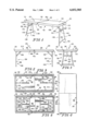
- FIG. 1 is a perspective view of a folding table in accordance with the present invention showing first and second table sections opened to a table position wherein top surfaces of the first and second table sections are aligned in coplanar relation to form an upwardly-facing elongated table surface and showing a leg assembly mounted to undersurfaces of each of the first and second table sections, each leg assembly including a leg moved to a support position and extending downwardly from the first and second table sections;
- FIG. 2 is a side elevation view of the folding table of FIG. 1 showing angled support struts extending from each of the legs to the respective first and second table sections to support the legs in the support positions;
- FIG. 3 is an end elevation view of the folding table of FIG. 2 showing one of the angled support struts being coupled to a central portion of an upper cross member of one of the legs by a coupling collar which is pivotably mounted to the upper cross member;
- FIG. 4 is a top plan view of the folding table of FIG. 3 showing the top surfaces of the first and second table sections aligned to form the elongated table surface;
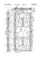
- FIG. 5 is a bottom plan view of the folding table of FIG. 4 showing the leg assemblies extended to respective support positions, the support struts extending from the legs to respective first and second channel members which are centrally mounted to undersurfaces of the first and second table sections, a pair of spaced-apart reinforcing assemblies mounted near lateral sides of the first and second table sections, and the reinforcing assemblies including a support rail extending across the first and second table sections and engaging respective first and second table rails to reinforce the first and second table sections in the table position;
- FIG. 6 is a bottom plan view of the folding table of FIG. 5 in the table position showing the leg assemblies in their respective stored positions having the support struts positioned to lie within longitudinal channels defined by side walls of the respective first and second channel members and showing the support rails in a reinforcing position spanning the first and second table sections, the support rails being positioned to lie within longitudinal channels defined by side walls of respective first and second table rails;
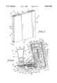
- FIG. 7 is a perspective view of the folding table of FIG. 1 showing the first and second table sections folded to a collapsed position having the top surfaces of the first and second table sections facing in opposite directions and having each of the leg assemblies in a stored position adjacent to respective undersurfaces of the first and second table sections so that the leg assemblies are hidden from view when the folding table is in the collapsed position;
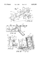
- FIG. 8 is a perspective view of the folding table of FIG. 7 in a partially opened position showing the first table section coupled to the second table section for pivoting movement about a transversely-extending central pivot axis, one of the leg assemblies in the stored position, the other of the leg assemblies unfolded to the support position having the respective support strut extending from the coupling collar to a respective channel member, the support rails angling between the first and second table sections, each of the support rails having a first end slidably mounted to the first table section by the first table rail, and each of the support rails having a second end pivotably mounted to the second table section by the second table rail;
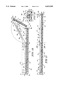
- FIG. 9 is an enlarged bottom plan view of the folding table similar to FIG. 6;
- FIG. 10 is a sectional view taken along line 10--10 of FIG. 9 showing one of the support rails in the reinforcing position, a sliding pin of the reinforcing assembly received by slots formed in the side walls of one of the first table rails so that the support rail can slide relative to the first table rail when the table is opened and collapsed, a slide pin of one of the leg assemblies mounted to the second section and received by slots formed in side walls of the channel member so that the support strut can slide relative to the channel member when the leg is pivoted between the stored position and the support position, and the first and second table sections each having end rims that project downwardly from ends of respective first and second table sections to shield the first and second table rails from view;
- FIG. 11 is a sectional view taken along line 11--11 of FIG. 9 showing the support rails positioned to lie within the channels formed by the side walls of the first table rails, the undersurface of the first table section formed to include a pair of spaced-apart recesses, each recess receiving a corresponding first table rail, the first table section formed to include an interior cavity, and the first table section having side rims that are integral with the end rim of the first table section and that shield the first table rails from view;
- FIG. 12 is a sectional view of the folding table of FIGS. 1-11 taken along line 12--12 of FIG. 11 through the longitudinal channels of the first and second table rails with portions broken away, showing the second table section in the collapsed position (in phantom) having the first end of the support rails adjacent to the end rims of the first and second table sections and having the second end of the support rails positioned to lie adjacent to an innermost slot edge of the slots formed in the first table rails, the second table section pivoted toward the table position to an intermediate position, and the sliding pin sliding within the slot toward the innermost slot edge of the slot formed in the first table rail while the support rails pivot relative to the second table rails and second table section;
- FIG. 13 is a sectional view of the folding table similar to FIG. 12, with portions broken away, showing the first and second table sections in the table position, the support rails in parallel relation with the first and second table sections inside the longitudinal channels of the first and second table rails, and the support rails having a bracing edge engaging mounting walls of the first and second support rails to prevent the first and second table sections from opening past the table position;
- FIG. 14 is a sectional view taken along line 14--14 of FIG. 13, with portions broken away, showing the side walls and mounting wall of the first table rails forming a U-shaped cross section defining the channel which receives the support rails, the first table rail being received by the recess formed in the undersurface of the first table section, and one of the side rims of the first table section shielding the first table rail from view;
- FIG. 15 is a perspective view of the first and second table rails of the folding table of FIGS. 1-14, with portions broken away, showing a first hinge plate mounted to the first table rail, a second hinge plate mounted to the second table rail, apertures formed in each of the first and second hinge plates, a pivot pin received by the apertures to pivotably couple the first and second table rails together, and chamfered corners on one side wall of each of the first and second table rails so that the pivot pin can be inserted into the apertures of the first and second hinge plates;
- FIG. 16 is a side view of the channel member of one of the leg assemblies, with portions broken away, showing a bent leaf spring mounted to a side wall of the channel member to bias a slide pin which couples the support strut to the channel member into engagement with an outermost slot edge of the slot to lock the leg in the support position;
- FIG. 17 is a perspective view of the coupling collar of each leg assembly which couples the support struts to the legs showing the coupling collar made up of two opposing identical half pieces, each half piece including a bent flange that mates with a straight flange of the opposing half piece to hold the half pieces together, each half piece including two fastening plates each having an aperture so that the half pieces can be fastened together, a transverse opening which receives an upper cross member of the leg for pivoting movement, and a longitudinal opening which receives the support strut; and
- FIG. 18 is a perspective view of an alternative embodiment of the folding table in accordance with the present invention showing each leg assembly having a pair of spaced-apart leg support linkages which are opened to an in-line configuration when a corresponding leg is extended to the support position to lock the leg in the support position and which are folded into a side-by-side configuration adjacent to the undersurface of a respective table section when a corresponding leg is pivoted to the stored position.
- a folding table 20 in accordance with the present invention includes a first table section 22 coupled to a second table section 24 for pivoting movement about a transversely-extending central pivot axis 26, a first leg assembly 28 mounted to first table section 22, and a second leg assembly 30 mounted to second table section 24, as shown in FIG. 1.
- First and second table sections 22, 24 can fold about pivot axis 26 between a table position, shown in FIGS. 1-5, wherein an end 32 of first table section 22 is horizontally spaced apart from an end 34 of second table section 24 and a collapsed position, shown best in FIG. 7, wherein end 32 of first table section 22 is adjacent to end 34 of second table section 24.
- First table section 22 includes a top surface 36 and second table section 24 includes a top surface 38.
- Top surface 36 of first table section 22 and top surface 38 of second table section 24 are aligned in coplanar relation to form an elongated upwardly-facing table surface 36, 38 when first and second table sections 22, 24 are in the table position, as shown in FIGS. 1 and 4.
- top surface 36 and top surface 38 are substantially parallel and face in opposite directions when first and second table sections 22, 24 are in the collapsed position, as shown in FIG. 7.
- First and second table sections 22, 24 are coupled together by a pair of spaced-apart reinforcing assemblies 40 as shown in FIG. 8.
- Each reinforcing assembly 40 is mounted to first and second table sections 22, 24 adjacent to a respective first and second lateral side 42, 43 of table 20.
- Each reinforcing assembly 40 includes a first table rail 44 mounted to an undersurface 46 of first table section 22, a second table rail 48 mounted to an undersurface 50 of second table section 24, and a support rail 52 slidably coupled to first table rail 44 and pivotably coupled to second table rail 48, as shown in FIGS. 6, 8 and 9.
- Reinforcing assembly 40 adjacent to first lateral side 42 of table 20 and the operation of reinforcing assembly adjacent to first lateral side 42 of table 20 is substantially the same as reinforcing assembly 40 adjacent to second lateral side 43 of table 20 and the operation of reinforcing assembly 40 adjacent to second lateral side 43 of table 20. Therefore, the description below of reinforcing assembly 40 adjacent to first lateral side 42 of table 20 and the operation of reinforcing assembly adjacent to first lateral side 42 of table 20 applies as well to reinforcing assembly 40 adjacent to second lateral side 43 of table 20 and the operation of reinforcing assembly 40 adjacent to second lateral side 43 of table 20 unless specifically noted otherwise.
- First table rail 44 includes a pair of spaced-apart side walls 54 and a mounting wall 56 connecting side walls 56 so that first table rail 44 has a U-shaped cross section defining a longitudinally-extending first channel 58 having uniform height and width.
- Mounting wall 56 is received by an elongated recess 57 formed in undersurface 46 of first table section 22 and is mounted to first table section 22 by suitable fastening means so that side walls 56 are perpendicular to undersurface 46 of first table section 22.
- second table rail 48 includes a pair of spaced-apart side walls 60 and a mounting wall 62 connecting side walls 60 so that second table rail 48 has a U-shaped cross section defining a longitudinally-extending second channel 64 having uniform height and width.
- Mounting wall 62 is received by an elongated recess 63 formed in undersurface 50 of second table section 24 and is mounted to second table section 24 by suitable fastening means so that side walls 60 are perpendicular to undersurface 50 of second table section 24.
- a plurality of screws 66 are used to fasten first and second table rails 44, 48 to respective first and second table sections 22, 24.
- First and second table rails 44, 48 are fixed to first and second table sections 22, 24, respectively, so that when first and second table sections 22, 24 are in the table position, first and second table rails 44, 48 are aligned in an end-to-end configuration having an end surface 68 of first table rail abutting an end surface 70 of second table rail 48, as shown in FIG. 15.
- first and second table rails 44, 48 are folded together in a side-by-side configuration having rail edges 72 of first table rail 44 abutting rail edges 74 of second table rail 48.
- Reinforcing assembly 40 includes a first hinge plate 76 attached to first table rail 44 and a second hinge plate 78 attached to second table rail 48, as shown in FIG. 15.
- First hinge plate 76 is formed to include a first aperture 80 and second hinge plate 78 is formed to include a second aperture 82.
- a pivot pin 84 is received by first and second apertures 80, 82 to pivotably couple first and second table rails 44, 48 to one another which ultimately pivotably couples first and second table sections 22, 24 to one another.
- the outer side wall 54, 60 of each of the first and second table rails 44, 48 have chamfered corners so that pivot pin 84 has room to be inserted into first and second apertures 80, 82 of first and second hinge plates 76, 78.
- Pivot pin 84 cooperates with first and second hinge plates 76, 78 to define central pivot axis 26 about which first and second table sections 22, 24 pivot.
- Support rail 52 includes a pair of spaced-apart bracing walls 86 and a bottom wall 88 connecting bracing walls 86 so that support rail 52 has a U-shaped cross section, as shown in FIGS. 11 and 14.
- Bottom wall 88 of support rail 52 has a width that is slightly narrower than mounting walls 56, 62 of first and second table rails 44, 48 allowing a first end 90 of support rail to be received within first channel 58 of first table rail 44 and allowing a second end 92 of support rail 52 to be received within second channel 64 of second table rail 48.
- Each bracing wall 86 of support rail 52 is formed to include an aperture 94 adjacent to first end 90 of support rail 52.
- Each side wall 54 of first table rail 44 is formed to include an elongated slot 96.
- a sliding pin 98 is received by apertures 94 and slots 96 so that first end 90 of support rail 52 is slidably coupled to first table section 22 by first table rail 44. Sliding pin 98 automatically slides in slots 96 during pivoting movement of first and second table sections 22, 24 about central pivot axis 26 between the table position and the collapsed position.
- each bracing wall 86 of support rail 52 is formed to include an aperture 100 adjacent to second end 92 of support rail 52 and each side wall 60 of second table rail 48 is formed to include an aperture 110.
- a pivot pin 112 is received by apertures 100 and apertures 110 so that second end 92 of support rail 52 is pivotably coupled to second table section 24 by second table rail 48.
- Support rail 52 automatically pivots relative to second table rail 48 and second table section 24 about a transversely-extending pivot axis 114 during pivoting movement of first and second table sections 22, 24 about central pivot axis 26 between the table position and the collapsed position.
- support rail 52 When first and second table sections 22, 24 are in the collapsed position, support rail 52 is substantially contained within first and second channels 58, 64 of first and second table rails 44, 48 in a stored position. In the stored position, approximately one half of support rail 52 is contained within first channel 58 of first table rail 44 and approximately one half of support rail 52 is contained within second channel 64 of second table rail 48 while the first and second table rails are in the side-by-side configuration.
- first end 90 of support rail 52 is adjacent to end 32 of first table section 22 and sliding pin 98 is adjacent to an outermost slot edge 116 defining an outer end of slot 96.
- second end 92 of support rail 52 is positioned to lie adjacent to slot 96, as shown best in FIG. 12 (in phantom).
- first and second table sections 22, 24 unfold about central pivot axis 26 from the collapsed position toward the table position, support rail 52 automatically pivots about pivot axis 114 relative to second table rail 48 pulling sliding pin 98 away from outermost slot edge 116 and toward an innermost slot edge 118 defining an inner end of slot 96 so that first end 90 of support rail 52 travels within first channel 58 toward central pivot axis 26.
- a substantial portion of support rail 52 is withdrawn from first and second channels 58, 62 during movement of first and second table sections 22, 24 between the table position and the collapsed position, as shown in FIGS. 8 and 12.
- support rail 52 is substantially contained within first and second channels 58, 64 of first and second table rails 44, 48 in a reinforcing position.
- first channel 58 of first table rail 44 approximately half of support rail 52 is contained within second channel 64 of second table rail 48 while the first and second table rails 44,48 are in the end-to-end configuration.
- bracing edges 120 of bracing walls 86 simultaneously engage mounting wall 56 of first table rail 44 and mounting wall 62 of second table rail 48 so that first and second table sections 22, 24 are reinforced in the table position and so that first and second table sections 22, 24 are prevented from opening past the table position.
- first and second table sections 22, 24 are in the table position and objects (not shown) are placed on top surfaces 36, 38 of first and second table sections 22, 24, the weight of the objects are distributed through sliding pin 98 and pivot pin 112 to first and second table rails 44, 48, respectively.
- Preferred and illustrative reinforcing assembly 40 is constructed so that support rail 52 has a length 122 that is approximately one third of a length 124 that is defined by first and second table rails 44, 48 when in the end-to-end configuration as shown in FIG. 9.
- Length 122 of support rail 52 is maximized so that bracing edges 120 contact as much of mounting wall 56 of first table rail 44 and mounting wall 62 of second table rail 48 as possible when first and second table sections 22, 24 are in the table position while still allowing first and second table sections 22, 24 to fold against one another in the collapsed position.
- Movement of reinforcing assembly 40 when first and second table sections 22, 24 are folded from the table position toward the collapsed position is similar but opposite to the movement of reinforcing assembly 40 when first and second table sections 22, 24 are unfolded from the collapsed position toward the table position.
- support rail 52 pushes sliding pin 98 away from innermost slot edge 118 and toward outermost slot edge 116, and first end 90 of support rail travels in first channel 58 of first table rail 48 away from central pivot axis 26.
- First and second table sections 22, 24 of preferred and illustrative table 20 are each made from a plastics material and are blow molded so that an interior cavity 126 is formed between top surfaces 36, 38 and undersurfaces 46, 50 of respective first and second table sections 22, 24.
- first and second table sections 22, 24 it is within the scope of the invention as presently perceived for first and second table sections 22, 24 to be made of a non-plastics material, such as wood, and to have a solid interior region rather than cavity 126.
- First and second table sections 22, 24 are each formed to include lateral rims 128 which project from top surfaces 36, 38 beyond undersurfaces 46, 50 along lateral sides 42, 43 of table 20 and end rims 130 which project from top surfaces 36, 38 beyond undersurfaces 46, 50 along ends 32, 34 of first and second table sections 22, 24, respectively.
- Lateral rims 128 and end rims 130 shield respective first and second table rails 44, 48 from view, as shown in FIGS. 1-4.
- Elongated recesses 57 in which first table rails 44 are received and elongated recesses 63 in which second table rails 48 are received are positioned to lie adjacent to a corresponding lateral rim 128, as shown in FIGS. 11 and 14.
- bottom surfaces 132 of lateral rims 128 of respective first and second table sections 22, 24 abut one another and bottom surfaces 134 of end rims 130 of respective first and second table sections 22, 24 abut one another so that both reinforcing assemblies 40 are substantially encased by first and second table sections 22, 24, as shown in FIG. 7.
- table 20 includes first leg assembly 28 mounted to first table section 22 and second leg assembly 30 mounted to second table section 24.
- First leg assembly 28 and the operation of first leg assembly 28 is substantially the same as second leg assembly 30 and the operation of second leg assembly 30. Therefore, the description below of first leg assembly 28 and the operation of first leg assembly 28 applies as well to second leg assembly 30 and the operation of second leg assembly 30 unless specifically noted otherwise.
- First leg assembly 28 includes a leg 136 having a pair of spaced-apart curved uprights 138, a lower cross member 140 extending transversely between uprights 138 adjacent to lower portions of uprights 138, an upper cross member 142 extending transversely between middle portions of uprights 138, and a pivot member 144 to which upper portions of uprights 138 are attached, as shown in FIGS. 6, 8 and 9.
- First leg assembly 28 also includes a support strut 146 which is pivotably coupled to a central portion of upper cross member 142 by a coupling collar 148 and a channel member 150 which is mounted to undersurface 46 of first table section 22 between lateral rims 128, as also shown in FIGS. 6, 8 and 9.
- Pivot member 144 is coupled to first table rails 44 for pivoting movement relative to first table section 22 by a pair of spaced-apart pivot collars 145, as shown in FIG. 9.
- Coupling collar 148 of preferred and illustrative table 20 is made up of two opposing identical half pieces 170 which are molded from a plastics material. Each half piece 170 is formed to include a bent flange 172 that mates with a straight flange 174 of opposing half piece 170 to hold half pieces 170 together, as shown in FIG. 17. In addition, each half piece 170 is formed to include two fastening plates 176 and each fastening plate is formed to include an aperture 178. Apertures 178 of each half piece 170 align so that a fastening bolt (not shown) or other suitable fastening element can be received by the aligned apertures to fasten half pieces 170 together.
- a transverse opening 180 which receives upper cross member 142 for pivoting movement is formed by half pieces 170.
- a longitudinal opening 182 which receives support strut 146 is also formed when half pieces 170 are fastened together.
- An aperture 184 is also provided on each half piece 170 so that coupling collar 148 can be fastened to support strut 146.
- Channel member 150 includes a pair of spaced-apart side walls 152 and a mounting wall 154 connecting side walls 152 so that channel member 150 has a U-shaped cross section defining a longitudinally-extending slide channel 156 having uniform height and width.
- Mounting wall 156 is fixed to undersurface 46 of first table section 22 by suitable fastening means and each side wall 152 is formed to include a slot 158.
- Slots 158 extend generally longitudinally and parallel with undersurface 46 but an end portion of slots 158 nearest to leg 136 is angled toward undersurface 46 as shown in FIGS. 10 and 16.
- Support strut 146 is coupled to channel member 150 by a slide pin 160 which is received by slots 158 for sliding movement.
- First leg assembly 28 has a stored position wherein leg 136 is folded against undersurface 46 of first table section 22.
- first and second leg assemblies 28, 30 are both in their respective stored positions, first and second table sections 22, 24 can be folded to the collapsed position without interference from first and second leg assemblies 28, 30.
- first leg assembly 28 When first leg assembly 28 is in the stored position, support strut 146 is positioned to lie within slide channel 156 between side walls 152 and slide pin 160 is positioned to lie adjacent to innermost slot edges 162 which define inner ends of slots 158, as shown in FIGS. 6 and 9.
- leg 136 can be manually pivoted from the stored position to a support position causing pivot member 144 to rotate within pivot collars 145 and causing upper cross member 142 to pull support strut 146 out of slide channel 156. Pivoting movement of leg 136 also causes coupling collar 148 to pivot relative to upper cross member 142 while slide pin 160 slides in slots 158 away from innermost slot edges 162 toward the angled end portions of slots 158.
- a bent leaf spring 164 engages slide pin 160 to urge slide pin into contact with outermost slot edges 166 which define outer ends of slots 158, as shown in FIG. 16.
- leg assembly 28 is in the support position having leg 136 extending away from undersurface 46 of first table section 22, as shown in FIGS. 1-5 and 8. Bent leaf spring 164 and channel member 150 cooperate to lock support strut 146 and leg 136 in the support position.
- slide pin 160 causes bent leaf spring 164 to deflect so that slide pin 160 can slide from the angled portion of slot 158 into the longitudinal portion of slot 158.
- leg assembly 28 from the support position toward the stored position is similar but opposite to the movement of leg assembly 28 from the stored position toward the table support position.
- support strut 146 pushes slide pin 160 away from outermost slot edges 166 and toward innermost slot edges 162, and upper cross member 142 pushes support strut 146 into slide channel 156 of channel member 150.
- An alternative embodiment of a folding table 21 in accordance with the present invention includes two leg assemblies 41 each of which is mounted to undersurfaces 46, 50 of respective first and second table sections 22, 24, as shown in FIG. 18.
- Each leg assembly 41 includes a pair of spaced-apart leg support linkages 190 having a first link 192 and a second link 194 pivotably coupled to first link 192.
- Each first link 192 is pivotably coupled to a corresponding curved upright 138 and each second link is pivotably coupled to a corresponding first or second table rail 44, 48.
- First and second links 192, 194 are opened to an in-line configuration when a corresponding leg 136 is extended to a support position to lock leg assembly 41 in the support position, as shown in FIG. 18.
- First and second links 192, 194 are folded into a side-by-side configuration adjacent to undersurfaces 46, 50 of first and second table sections 22, 24 when leg assemblies 41 are moved to a stored position having legs 136 adjacent to undersurfaces 46, 50.
Abstract
Description
Claims (50)
Priority Applications (2)
| Application Number | Priority Date | Filing Date | Title |
|---|---|---|---|
| US08/908,625 US6032585A (en) | 1996-08-09 | 1997-08-07 | Folding banquet table |
| US09/058,012 US6058853A (en) | 1996-08-09 | 1998-04-09 | Banquet table |
Applications Claiming Priority (2)
| Application Number | Priority Date | Filing Date | Title |
|---|---|---|---|
| US2360496P | 1996-08-09 | 1996-08-09 | |
| US08/908,625 US6032585A (en) | 1996-08-09 | 1997-08-07 | Folding banquet table |
Related Child Applications (2)
| Application Number | Title | Priority Date | Filing Date |
|---|---|---|---|
| US09/058,012 Continuation-In-Part US6058853A (en) | 1996-08-09 | 1998-04-09 | Banquet table |
| US29/104,043 Continuation USD423258S (en) | 1999-04-27 | 1999-04-27 | Pair of table legs |
Publications (1)
| Publication Number | Publication Date |
|---|---|
| US6032585A true US6032585A (en) | 2000-03-07 |
Family
ID=26697383
Family Applications (1)
| Application Number | Title | Priority Date | Filing Date |
|---|---|---|---|
| US08/908,625 Expired - Fee Related US6032585A (en) | 1996-08-09 | 1997-08-07 | Folding banquet table |
Country Status (1)
| Country | Link |
|---|---|
| US (1) | US6032585A (en) |
Cited By (42)
| Publication number | Priority date | Publication date | Assignee | Title |
|---|---|---|---|---|
| FR2819386A1 (en) * | 2001-01-12 | 2002-07-19 | Cosco Man Inc | FOLDING TABLE |
| US6422157B2 (en) | 1999-12-21 | 2002-07-23 | Cosco Management, Inc. | Banquet table with pivotable legs |
| US6530331B2 (en) | 1998-10-21 | 2003-03-11 | Lifetime Products, Inc. | Portable folding utility table with integral receiving members |
| US20030121460A1 (en) * | 2001-12-29 | 2003-07-03 | Leng Lou-Hao | Button actuator for use with leg lock of table |
| US20030121459A1 (en) * | 2001-12-08 | 2003-07-03 | Leng Lou-Hao | Table |
| US20030164123A1 (en) * | 2002-03-01 | 2003-09-04 | Leng Lou-Hao | Table with leg lock |
| US20030230219A1 (en) * | 2002-04-09 | 2003-12-18 | Strong L. Curtis | Portable folding table |
| US20040070235A1 (en) * | 2002-08-12 | 2004-04-15 | Gregory Michael A. | Portable picnic table |
| US20040094076A1 (en) * | 2002-07-10 | 2004-05-20 | Ju-Young Jin | Folding table |
| US20040187747A1 (en) * | 2002-09-24 | 2004-09-30 | Jin Shenghao | Utility table |
| US20040187748A1 (en) * | 2002-09-27 | 2004-09-30 | Jin Shenghao | Table having H-center support assembly |
| US20040187749A1 (en) * | 2002-09-27 | 2004-09-30 | Chen Zhurong | Folding table |
| US20040221773A1 (en) * | 2003-05-08 | 2004-11-11 | Edward Zheng | Foldable table with four bar link |
| US20040237856A1 (en) * | 2002-09-24 | 2004-12-02 | Jin Shenghao | Utility table |
| US20040244656A1 (en) * | 2002-10-11 | 2004-12-09 | Jin Shenghao | Table with center support assembly |
| US20050005826A1 (en) * | 2002-04-09 | 2005-01-13 | Strong L. Curtis | Portable folding table with locking hinge |
| US6945178B1 (en) * | 1998-09-09 | 2005-09-20 | Lifetimeproducts, Inc. | Collapsible table with blow molded table top |
| US20050241550A1 (en) * | 2004-04-22 | 2005-11-03 | Martin Neunzert | Retainer for securing a table in a folded position |
| US6971321B1 (en) | 2002-04-09 | 2005-12-06 | Lifetime Products, Inc. | Table leg locking mechanism |
| US20050274302A1 (en) * | 2002-07-10 | 2005-12-15 | Ju-Young Jin | Fold-in-half table |
| US20050274304A1 (en) * | 2004-06-02 | 2005-12-15 | Strong L C | Table |
| US20050279259A1 (en) * | 1999-01-11 | 2005-12-22 | Strong L C | Frame for a table top |
| US20060021553A1 (en) * | 2004-07-30 | 2006-02-02 | Pleiman Brian R | Table with folding support |
| US20060021552A1 (en) * | 2004-07-30 | 2006-02-02 | Pleiman Brian R | Table support structure |
| US20060021551A1 (en) * | 2004-07-30 | 2006-02-02 | Pleiman Brian R | Table with folding leg |
| US7093893B1 (en) | 2004-07-19 | 2006-08-22 | Gary Bunde | Folding bench |
| US20070006784A1 (en) * | 2005-07-07 | 2007-01-11 | Thrush Bruce A | Table with folding legs and internal frame |
| US20080078310A1 (en) * | 2006-09-27 | 2008-04-03 | Vannimwegen Edward G | Table |
| US20080202390A1 (en) * | 2007-02-22 | 2008-08-28 | Paul Branch | Handle for a portable table |
| US20090056593A1 (en) * | 2007-08-31 | 2009-03-05 | Robert Farber | Folding Table With Transport Mechanism |
| US20090078173A1 (en) * | 2007-09-24 | 2009-03-26 | Katie Staples Topham | Table |
| US7735431B2 (en) | 2003-04-08 | 2010-06-15 | Lifetime Products, Inc. | Handle for a portable table |
| US7938496B1 (en) * | 2009-12-07 | 2011-05-10 | Cattanach Victor H | Hinged turntable |
| US8342107B2 (en) | 2002-04-09 | 2013-01-01 | Lifetime Products, Inc. | High-strength, lightweight blow-molded plastic structures |
| US20130119039A1 (en) * | 2011-11-11 | 2013-05-16 | Lincoln Global, Inc. | Educational welding cell unit |
| US8555788B2 (en) | 2011-06-06 | 2013-10-15 | Grosfillex Sas | Table including at least one leg that can be turned either way up |
| EP2735246A1 (en) * | 2012-11-23 | 2014-05-28 | Meyra GmbH | Folding frame |
| WO2014209223A1 (en) * | 2013-06-27 | 2014-12-31 | Qoolcreations Pte Ltd | Pocket size foldable or collapsible stool |
| CN104942778A (en) * | 2015-07-22 | 2015-09-30 | 苏州新区枫桥净化设备厂 | Detachable worktable |
| US20180249820A1 (en) * | 2017-03-06 | 2018-09-06 | Dorel Home Furnishings, Inc. | Banquet table |
| CN111907712A (en) * | 2019-05-07 | 2020-11-10 | B/E航空公司 | Passenger suite including table mechanism with vertical, translational and rotational adjustment |
| US20220395089A1 (en) * | 2021-06-15 | 2022-12-15 | Lifetime Products, Inc. | Locking mechanism for a table leg assembly |
Citations (21)
| Publication number | Priority date | Publication date | Assignee | Title |
|---|---|---|---|---|
| US1614187A (en) * | 1923-09-26 | 1927-01-11 | Shirley M Coggins | Adjustable-leg foldable table |
| US1976140A (en) * | 1932-06-08 | 1934-10-09 | Donald W Paul | Furniture |
| GB626807A (en) * | 1947-07-25 | 1949-07-21 | Dunlop Rubber Co | Improvements in tables |
| US2542394A (en) * | 1948-08-25 | 1951-02-20 | Cohen Boris | Foldable table |
| US3025120A (en) * | 1960-10-18 | 1962-03-13 | Howe Folding Furniture Inc | Folding tables |
| US3170417A (en) * | 1963-12-09 | 1965-02-23 | James E Avidiya | Combination door and ironing board |
| US3368504A (en) * | 1967-06-28 | 1968-02-13 | All Luminum Products Inc | Locking mechanism for foldable tables |
| US4157089A (en) * | 1976-12-21 | 1979-06-05 | Janice Margaret Loughrey | Physiotherapy table |
| US4838180A (en) * | 1988-03-04 | 1989-06-13 | Ditto Sales, Inc. | Folding table leg apparatus |
| US4841877A (en) * | 1986-10-14 | 1989-06-27 | Virco Mfg. Corporation | Table |
| US4862611A (en) * | 1987-11-19 | 1989-09-05 | Wright Margaret J | Portable, door-hanging ironing board |
| US5109778A (en) * | 1991-04-29 | 1992-05-05 | Berco Industries | Folding table |
| US5154441A (en) * | 1992-01-28 | 1992-10-13 | White Richard W | Folding and rolling two surface table |
| US5279233A (en) * | 1992-02-14 | 1994-01-18 | Falcon Products, Inc. | Folding table mechanism |
| US5323713A (en) * | 1992-07-29 | 1994-06-28 | Northwest Metal Products, Inc. | Locking mechanism for folding table legs |
| US5357872A (en) * | 1992-11-20 | 1994-10-25 | Globe Business Furniture, Inc. | Folding table |
| US5365861A (en) * | 1992-01-14 | 1994-11-22 | Ditto Sales, Inc. | Latch mechanism for folding table leg |
| US5390610A (en) * | 1992-09-10 | 1995-02-21 | Ditto Sales | Carrying handles for a folding table leg apparatus |
| US5421272A (en) * | 1992-11-20 | 1995-06-06 | Globe Business Furniture, Inc. | Folding table |
| US5445085A (en) * | 1992-08-27 | 1995-08-29 | Lawn Comfort S.A. | Folding table |
| US5623882A (en) * | 1993-12-13 | 1997-04-29 | Alltrista Corporation | Plastic table structure |
-
1997
- 1997-08-07 US US08/908,625 patent/US6032585A/en not_active Expired - Fee Related
Patent Citations (21)
| Publication number | Priority date | Publication date | Assignee | Title |
|---|---|---|---|---|
| US1614187A (en) * | 1923-09-26 | 1927-01-11 | Shirley M Coggins | Adjustable-leg foldable table |
| US1976140A (en) * | 1932-06-08 | 1934-10-09 | Donald W Paul | Furniture |
| GB626807A (en) * | 1947-07-25 | 1949-07-21 | Dunlop Rubber Co | Improvements in tables |
| US2542394A (en) * | 1948-08-25 | 1951-02-20 | Cohen Boris | Foldable table |
| US3025120A (en) * | 1960-10-18 | 1962-03-13 | Howe Folding Furniture Inc | Folding tables |
| US3170417A (en) * | 1963-12-09 | 1965-02-23 | James E Avidiya | Combination door and ironing board |
| US3368504A (en) * | 1967-06-28 | 1968-02-13 | All Luminum Products Inc | Locking mechanism for foldable tables |
| US4157089A (en) * | 1976-12-21 | 1979-06-05 | Janice Margaret Loughrey | Physiotherapy table |
| US4841877A (en) * | 1986-10-14 | 1989-06-27 | Virco Mfg. Corporation | Table |
| US4862611A (en) * | 1987-11-19 | 1989-09-05 | Wright Margaret J | Portable, door-hanging ironing board |
| US4838180A (en) * | 1988-03-04 | 1989-06-13 | Ditto Sales, Inc. | Folding table leg apparatus |
| US5109778A (en) * | 1991-04-29 | 1992-05-05 | Berco Industries | Folding table |
| US5365861A (en) * | 1992-01-14 | 1994-11-22 | Ditto Sales, Inc. | Latch mechanism for folding table leg |
| US5154441A (en) * | 1992-01-28 | 1992-10-13 | White Richard W | Folding and rolling two surface table |
| US5279233A (en) * | 1992-02-14 | 1994-01-18 | Falcon Products, Inc. | Folding table mechanism |
| US5323713A (en) * | 1992-07-29 | 1994-06-28 | Northwest Metal Products, Inc. | Locking mechanism for folding table legs |
| US5445085A (en) * | 1992-08-27 | 1995-08-29 | Lawn Comfort S.A. | Folding table |
| US5390610A (en) * | 1992-09-10 | 1995-02-21 | Ditto Sales | Carrying handles for a folding table leg apparatus |
| US5357872A (en) * | 1992-11-20 | 1994-10-25 | Globe Business Furniture, Inc. | Folding table |
| US5421272A (en) * | 1992-11-20 | 1995-06-06 | Globe Business Furniture, Inc. | Folding table |
| US5623882A (en) * | 1993-12-13 | 1997-04-29 | Alltrista Corporation | Plastic table structure |
Non-Patent Citations (11)
| Title |
|---|
| CORE A GATOR folding table literature from Virco Mfg. Corporation, onepage, 1996. * |
| CORE-A-GATOR™ folding table literature from Virco Mfg. Corporation, onepage, 1996. |
| Folding table advertisement, CHEF S catalog, p. C598, date unknown. * |
| Folding table advertisement, CHEF'S catalog, p. C598, date unknown. |
| Folding table literature from Business & Institutional Furniture Company, two pages, date unknown. * |
| Folding table literature from Palmer Snyder, two pages, 1996. * |
| Folding table literature, Adirondack Direct catalog, cover sheet and p. 72, date unknown. * |
| Folding table literature, CH Office Products, p. 414, date unknown. * |
| Folding table literature, Meco Corporation, two pages, date unknown. * |
| MITY LITE Tables & Chairs catalog, four pages, date unknown. * |
| MITY-LITE™ Tables & Chairs catalog, four pages, date unknown. |
Cited By (99)
| Publication number | Priority date | Publication date | Assignee | Title |
|---|---|---|---|---|
| US6945178B1 (en) * | 1998-09-09 | 2005-09-20 | Lifetimeproducts, Inc. | Collapsible table with blow molded table top |
| US20050269845A1 (en) * | 1998-09-09 | 2005-12-08 | Nye Stephen F | Table with foldable legs |
| US7373889B2 (en) * | 1998-09-09 | 2008-05-20 | Lifetime Products, Inc. | Table with foldable legs |
| US8739707B2 (en) | 1998-10-21 | 2014-06-03 | Lifetime Products, Inc. | Table top |
| US8904623B2 (en) | 1998-10-21 | 2014-12-09 | Lifetime Products, Inc. | Table |
| US20070034123A1 (en) * | 1998-10-21 | 2007-02-15 | Stanford Carl R | Table top with a plurality of closely spaced depressions |
| US7806060B2 (en) | 1998-10-21 | 2010-10-05 | Lifetime Products, Inc. | Table top with a plurality of closely spaced depressions |
| US6655301B2 (en) | 1998-10-21 | 2003-12-02 | Lifetime Products, Inc. | Portable folding utility table with frame connected to integral lip |
| US20070051287A1 (en) * | 1998-10-21 | 2007-03-08 | Stanford Carl R | Table with integral receiving members |
| US20070089650A1 (en) * | 1998-10-21 | 2007-04-26 | Stanford Carl R | Table with foldable legs |
| US20080105170A1 (en) * | 1998-10-21 | 2008-05-08 | Stanford Carl R | Table |
| US20060266266A1 (en) * | 1998-10-21 | 2006-11-30 | Stanford Carl R | Table including a blow-molded plastic table top and an attached frame |
| US20040099189A1 (en) * | 1998-10-21 | 2004-05-27 | Stanford Carl R. | Portable folding utility table with frame connected to integral lip |
| US20080105171A1 (en) * | 1998-10-21 | 2008-05-08 | Stanford Carl R | Table |
| US8438982B2 (en) | 1998-10-21 | 2013-05-14 | Lifetime Products, Inc. | Table with a table top constructed from molded plastic |
| US8381666B2 (en) | 1998-10-21 | 2013-02-26 | Lifetime Products, Inc. | Table top constructed from molded plastic |
| US8381665B2 (en) | 1998-10-21 | 2013-02-26 | Lifetime Products, Inc. | Table top constructed from molded plastic |
| US8375871B2 (en) | 1998-10-21 | 2013-02-19 | Lifetime Products, Inc. | Table top with a plurality of closely spaced depressions |
| US8074582B2 (en) | 1998-10-21 | 2011-12-13 | Lifetime Products, Inc. | Table with a table top including a plurality of integrally formed depressions |
| US8069796B2 (en) | 1998-10-21 | 2011-12-06 | Lifetime Products, Inc. | Table with molded plastic table top |
| US6832563B2 (en) | 1998-10-21 | 2004-12-21 | Lifetime Products, Inc. | Portable folding utility table with integral receiving members |
| US8042476B2 (en) | 1998-10-21 | 2011-10-25 | Lifetime Products, Inc. | Table with molded plastic table top |
| US20110017109A1 (en) * | 1998-10-21 | 2011-01-27 | Stanford Carl R | Table top with a plurality of closely spaced depressions |
| US20060011109A1 (en) * | 1998-10-21 | 2006-01-19 | Sanford Carl R | Table with integral receiving members |
| US20060000394A1 (en) * | 1998-10-21 | 2006-01-05 | Stanford Carl R | Table with foldable legs |
| US9237801B2 (en) | 1998-10-21 | 2016-01-19 | Lifetime Products, Inc. | Table top with a plurality of closely spaced depressions |
| US20080110379A1 (en) * | 1998-10-21 | 2008-05-15 | Stanford Carl R | Table |
| US20090229499A1 (en) * | 1998-10-21 | 2009-09-17 | Stanford Carl R | Table |
| US6550404B2 (en) | 1998-10-21 | 2003-04-22 | Lifetime Products, Inc. | Portable folding utility table with integral table top and lip |
| US20050211141A1 (en) * | 1998-10-21 | 2005-09-29 | Stanford Carl R | Table including a blow-molded plastic table top and an attached frame |
| US20090223424A1 (en) * | 1998-10-21 | 2009-09-10 | Stanford Carl R | Table |
| US6530331B2 (en) | 1998-10-21 | 2003-03-11 | Lifetime Products, Inc. | Portable folding utility table with integral receiving members |
| US20050268827A1 (en) * | 1998-10-21 | 2005-12-08 | Stanford Carl R | Table top with a plurality of closely spaced depressions |
| US20080110378A1 (en) * | 1998-10-21 | 2008-05-15 | Stanford Carl R | Table top with a plurality of closely spaced depressions |
| US20050279259A1 (en) * | 1999-01-11 | 2005-12-22 | Strong L C | Frame for a table top |
| US6422157B2 (en) | 1999-12-21 | 2002-07-23 | Cosco Management, Inc. | Banquet table with pivotable legs |
| US6752091B2 (en) | 2001-01-12 | 2004-06-22 | Cosco Management, Inc. | Folding banquet table |
| FR2819386A1 (en) * | 2001-01-12 | 2002-07-19 | Cosco Man Inc | FOLDING TABLE |
| US6694897B2 (en) | 2001-12-08 | 2004-02-24 | Cosco Management, Inc. | Table |
| US20030121459A1 (en) * | 2001-12-08 | 2003-07-03 | Leng Lou-Hao | Table |
| US20030121460A1 (en) * | 2001-12-29 | 2003-07-03 | Leng Lou-Hao | Button actuator for use with leg lock of table |
| US6920833B2 (en) | 2001-12-29 | 2005-07-26 | Cosco Management, Inc. | Button actuator for use with leg lock of table |
| US6920832B2 (en) | 2002-03-01 | 2005-07-26 | Cosco Management, Inc. | Table with leg lock |
| US20030164123A1 (en) * | 2002-03-01 | 2003-09-04 | Leng Lou-Hao | Table with leg lock |
| EP1499214A4 (en) * | 2002-04-09 | 2005-06-29 | Lifetime Prod Inc | Portable folding table |
| US20050005826A1 (en) * | 2002-04-09 | 2005-01-13 | Strong L. Curtis | Portable folding table with locking hinge |
| US20030230219A1 (en) * | 2002-04-09 | 2003-12-18 | Strong L. Curtis | Portable folding table |
| US7096799B2 (en) | 2002-04-09 | 2006-08-29 | Lifetime Products, Inc. | Portable folding table |
| US7475644B2 (en) | 2002-04-09 | 2009-01-13 | Lifetime Products, Inc. | Portable folding table |
| US7640870B2 (en) | 2002-04-09 | 2010-01-05 | Lifetime Products, Inc. | Portable folding table with locking hinge |
| US6971321B1 (en) | 2002-04-09 | 2005-12-06 | Lifetime Products, Inc. | Table leg locking mechanism |
| US20060288918A1 (en) * | 2002-04-09 | 2006-12-28 | Strong L C | Portable folding table |
| US8342107B2 (en) | 2002-04-09 | 2013-01-01 | Lifetime Products, Inc. | High-strength, lightweight blow-molded plastic structures |
| EP1499214A1 (en) * | 2002-04-09 | 2005-01-26 | Lifetime Products, Inc. | Portable folding table |
| US20040094076A1 (en) * | 2002-07-10 | 2004-05-20 | Ju-Young Jin | Folding table |
| US20050274302A1 (en) * | 2002-07-10 | 2005-12-15 | Ju-Young Jin | Fold-in-half table |
| US7461601B2 (en) | 2002-07-10 | 2008-12-09 | Lifetime Products, Inc. | Fold-in-half table |
| US7475641B2 (en) | 2002-07-10 | 2009-01-13 | Lifetime Products, Inc. | Folding table |
| US6883864B2 (en) | 2002-08-12 | 2005-04-26 | Rubbermaid, Inc. | Portable picnic table |
| US20040070235A1 (en) * | 2002-08-12 | 2004-04-15 | Gregory Michael A. | Portable picnic table |
| US20040237856A1 (en) * | 2002-09-24 | 2004-12-02 | Jin Shenghao | Utility table |
| US20040187747A1 (en) * | 2002-09-24 | 2004-09-30 | Jin Shenghao | Utility table |
| US20040187749A1 (en) * | 2002-09-27 | 2004-09-30 | Chen Zhurong | Folding table |
| US20040187748A1 (en) * | 2002-09-27 | 2004-09-30 | Jin Shenghao | Table having H-center support assembly |
| US7278361B2 (en) | 2002-09-27 | 2007-10-09 | Lifetime Products, Inc. | Folding table |
| US20040244656A1 (en) * | 2002-10-11 | 2004-12-09 | Jin Shenghao | Table with center support assembly |
| US8156875B2 (en) | 2003-04-08 | 2012-04-17 | Lifetime Products, Inc. | Handle for a portable table |
| US7735431B2 (en) | 2003-04-08 | 2010-06-15 | Lifetime Products, Inc. | Handle for a portable table |
| US20100242809A1 (en) * | 2003-04-08 | 2010-09-30 | Martin Neunzert | Handle for a portable table |
| US6928934B2 (en) * | 2003-05-08 | 2005-08-16 | Edward Zheng | Foldable table with four bar link |
| US20040221773A1 (en) * | 2003-05-08 | 2004-11-11 | Edward Zheng | Foldable table with four bar link |
| US20050241550A1 (en) * | 2004-04-22 | 2005-11-03 | Martin Neunzert | Retainer for securing a table in a folded position |
| US7634969B2 (en) | 2004-04-22 | 2009-12-22 | Lifetime Products, Inc. | Retainer for securing a table in a folded position |
| US7299753B2 (en) | 2004-06-02 | 2007-11-27 | Strong L Curtis | Table |
| US20050274304A1 (en) * | 2004-06-02 | 2005-12-15 | Strong L C | Table |
| US7093893B1 (en) | 2004-07-19 | 2006-08-22 | Gary Bunde | Folding bench |
| US20060021551A1 (en) * | 2004-07-30 | 2006-02-02 | Pleiman Brian R | Table with folding leg |
| US20060021553A1 (en) * | 2004-07-30 | 2006-02-02 | Pleiman Brian R | Table with folding support |
| US20060021552A1 (en) * | 2004-07-30 | 2006-02-02 | Pleiman Brian R | Table support structure |
| US20070006784A1 (en) * | 2005-07-07 | 2007-01-11 | Thrush Bruce A | Table with folding legs and internal frame |
| US20080078310A1 (en) * | 2006-09-27 | 2008-04-03 | Vannimwegen Edward G | Table |
| US8091490B2 (en) | 2007-02-22 | 2012-01-10 | Lifetime Products, Inc. | Handle for a portable table |
| US20080202390A1 (en) * | 2007-02-22 | 2008-08-28 | Paul Branch | Handle for a portable table |
| US7574964B2 (en) * | 2007-08-31 | 2009-08-18 | Gsc Technologies Corporation | Folding table with transport mechanism |
| US7987800B2 (en) | 2007-08-31 | 2011-08-02 | Gsc Technologies Corporation | Folding table with transport mechanism |
| AU2007249094B2 (en) * | 2007-08-31 | 2010-11-25 | Gsc Technologies Inc. | Folding table with transport mechanism |
| US20090056593A1 (en) * | 2007-08-31 | 2009-03-05 | Robert Farber | Folding Table With Transport Mechanism |
| US20090301358A1 (en) * | 2007-08-31 | 2009-12-10 | Robert Farber | Folding table with transport mechanism |
| US7975625B2 (en) | 2007-09-24 | 2011-07-12 | Lifetime Products, Inc. | Folding table |
| US20090078173A1 (en) * | 2007-09-24 | 2009-03-26 | Katie Staples Topham | Table |
| US7938496B1 (en) * | 2009-12-07 | 2011-05-10 | Cattanach Victor H | Hinged turntable |
| US8555788B2 (en) | 2011-06-06 | 2013-10-15 | Grosfillex Sas | Table including at least one leg that can be turned either way up |
| US20130119039A1 (en) * | 2011-11-11 | 2013-05-16 | Lincoln Global, Inc. | Educational welding cell unit |
| EP2735246A1 (en) * | 2012-11-23 | 2014-05-28 | Meyra GmbH | Folding frame |
| WO2014209223A1 (en) * | 2013-06-27 | 2014-12-31 | Qoolcreations Pte Ltd | Pocket size foldable or collapsible stool |
| CN104942778A (en) * | 2015-07-22 | 2015-09-30 | 苏州新区枫桥净化设备厂 | Detachable worktable |
| US20180249820A1 (en) * | 2017-03-06 | 2018-09-06 | Dorel Home Furnishings, Inc. | Banquet table |
| CN111907712A (en) * | 2019-05-07 | 2020-11-10 | B/E航空公司 | Passenger suite including table mechanism with vertical, translational and rotational adjustment |
| US20220395089A1 (en) * | 2021-06-15 | 2022-12-15 | Lifetime Products, Inc. | Locking mechanism for a table leg assembly |
Similar Documents
| Publication | Publication Date | Title |
|---|---|---|
| US6032585A (en) | Folding banquet table | |
| US8857350B2 (en) | Modular folding table | |
| US4883314A (en) | Folding table and seat assembly | |
| CA2501619C (en) | Table with center support assembly | |
| US5943968A (en) | Collapsible support structure | |
| US20070056485A1 (en) | Foldable frame structure for foldable table | |
| US4560030A (en) | Folding ladder | |
| CA2284151A1 (en) | Folding trailer with expandable bed assembly | |
| US5720405A (en) | Collapsible pallet with side walls hinged to the base by links | |
| US4318353A (en) | Table with folding legs | |
| US4106141A (en) | Bed frame | |
| US7174838B2 (en) | Collapsible table | |
| US4301559A (en) | Sofa bed mechanism | |
| US4646657A (en) | Collapsible table | |
| US2755153A (en) | Folding sectional top table | |
| US3152561A (en) | Collapsible ironing table construction | |
| GB2182846A (en) | Extensible table | |
| US5927212A (en) | Table with folding leaves | |
| US2866208A (en) | Foldable cot | |
| US5957061A (en) | Banquet table | |
| CN217524418U (en) | Bedstead folding supporting device, bedstead and bed | |
| US4842099A (en) | Foldable ladder | |
| EP1033094B1 (en) | Foldable frame for furniture | |
| US20040194675A1 (en) | Folding table with handles | |
| US3386112A (en) | Folding crib |
Legal Events
| Date | Code | Title | Description |
|---|---|---|---|
| AS | Assignment |
Owner name: COSCO, INC., INDIANA Free format text: ASSIGNMENT OF ASSIGNORS INTEREST;ASSIGNOR:PINCH, DANIEL R.;REEL/FRAME:009677/0794 Effective date: 19981125 |
|
| AS | Assignment |
Owner name: COSCO MANAGEMENT, INC., DELAWARE Free format text: ASSIGNMENT OF ASSIGNORS INTEREST;ASSIGNOR:COSCO, INC;REEL/FRAME:010263/0474 Effective date: 19980601 |
|
| AS | Assignment |
Owner name: COSCO MANAGEMENT, INC., DELAWARE Free format text: RE-RECORD TO CORRECT PATENT NUMBER 4456303 PREVIOUSLY RECORDED AT REEL 010263, FRAME 0474.;ASSIGNOR:COSCO, INC.;REEL/FRAME:010814/0495 Effective date: 19980601 |
|
| FEPP | Fee payment procedure |
Free format text: PAYOR NUMBER ASSIGNED (ORIGINAL EVENT CODE: ASPN); ENTITY STATUS OF PATENT OWNER: LARGE ENTITY |
|
| FPAY | Fee payment |
Year of fee payment: 4 |
|
| REMI | Maintenance fee reminder mailed | ||
| LAPS | Lapse for failure to pay maintenance fees | ||
| STCH | Information on status: patent discontinuation |
Free format text: PATENT EXPIRED DUE TO NONPAYMENT OF MAINTENANCE FEES UNDER 37 CFR 1.362 |
|
| FP | Lapsed due to failure to pay maintenance fee |
Effective date: 20080307 |