US6033061A - Ink supply for impulse ink jet system, said ink supply including a cap having a threaded perphery, a valve supported by said cap and a projection for extending from the cap into an ink reservoir - Google Patents
Ink supply for impulse ink jet system, said ink supply including a cap having a threaded perphery, a valve supported by said cap and a projection for extending from the cap into an ink reservoir Download PDFInfo
- Publication number
- US6033061A US6033061A US08/827,769 US82776997A US6033061A US 6033061 A US6033061 A US 6033061A US 82776997 A US82776997 A US 82776997A US 6033061 A US6033061 A US 6033061A
- Authority
- US
- United States
- Prior art keywords
- ink
- ink supply
- opening
- cap
- reservoir
- Prior art date
- Legal status (The legal status is an assumption and is not a legal conclusion. Google has not performed a legal analysis and makes no representation as to the accuracy of the status listed.)
- Expired - Lifetime
Links
- 230000007246 mechanism Effects 0.000 claims abstract description 15
- 230000008878 coupling Effects 0.000 claims description 4
- 238000010168 coupling process Methods 0.000 claims description 4
- 238000005859 coupling reaction Methods 0.000 claims description 4
- 230000004323 axial length Effects 0.000 claims 12
- 238000003780 insertion Methods 0.000 claims 3
- 230000037431 insertion Effects 0.000 claims 3
- 238000013459 approach Methods 0.000 claims 2
- 230000006835 compression Effects 0.000 claims 2
- 238000007906 compression Methods 0.000 claims 2
- 230000002572 peristaltic effect Effects 0.000 abstract description 20
- 230000037452 priming Effects 0.000 abstract description 14
- 230000005484 gravity Effects 0.000 abstract description 2
- 239000000976 ink Substances 0.000 description 97
- 238000005086 pumping Methods 0.000 description 18
- 239000007788 liquid Substances 0.000 description 5
- 238000000034 method Methods 0.000 description 4
- 239000000463 material Substances 0.000 description 3
- 230000003068 static effect Effects 0.000 description 3
- 238000013022 venting Methods 0.000 description 3
- 210000003811 finger Anatomy 0.000 description 2
- 230000004044 response Effects 0.000 description 2
- 241000272525 Anas platyrhynchos Species 0.000 description 1
- 229920002292 Nylon 6 Polymers 0.000 description 1
- 230000009471 action Effects 0.000 description 1
- 230000000881 depressing effect Effects 0.000 description 1
- 238000001914 filtration Methods 0.000 description 1
- 238000012986 modification Methods 0.000 description 1
- 230000004048 modification Effects 0.000 description 1
- NJPPVKZQTLUDBO-UHFFFAOYSA-N novaluron Chemical compound C1=C(Cl)C(OC(F)(F)C(OC(F)(F)F)F)=CC=C1NC(=O)NC(=O)C1=C(F)C=CC=C1F NJPPVKZQTLUDBO-UHFFFAOYSA-N 0.000 description 1
- 239000004033 plastic Substances 0.000 description 1
- 210000003813 thumb Anatomy 0.000 description 1
Images
Classifications
-
- B—PERFORMING OPERATIONS; TRANSPORTING
- B41—PRINTING; LINING MACHINES; TYPEWRITERS; STAMPS
- B41J—TYPEWRITERS; SELECTIVE PRINTING MECHANISMS, i.e. MECHANISMS PRINTING OTHERWISE THAN FROM A FORME; CORRECTION OF TYPOGRAPHICAL ERRORS
- B41J2/00—Typewriters or selective printing mechanisms characterised by the printing or marking process for which they are designed
- B41J2/005—Typewriters or selective printing mechanisms characterised by the printing or marking process for which they are designed characterised by bringing liquid or particles selectively into contact with a printing material
- B41J2/01—Ink jet
- B41J2/17—Ink jet characterised by ink handling
- B41J2/175—Ink supply systems ; Circuit parts therefor
- B41J2/17503—Ink cartridges
- B41J2/17506—Refilling of the cartridge
-
- B—PERFORMING OPERATIONS; TRANSPORTING
- B41—PRINTING; LINING MACHINES; TYPEWRITERS; STAMPS
- B41J—TYPEWRITERS; SELECTIVE PRINTING MECHANISMS, i.e. MECHANISMS PRINTING OTHERWISE THAN FROM A FORME; CORRECTION OF TYPOGRAPHICAL ERRORS
- B41J2/00—Typewriters or selective printing mechanisms characterised by the printing or marking process for which they are designed
- B41J2/005—Typewriters or selective printing mechanisms characterised by the printing or marking process for which they are designed characterised by bringing liquid or particles selectively into contact with a printing material
- B41J2/01—Ink jet
- B41J2/17—Ink jet characterised by ink handling
- B41J2/175—Ink supply systems ; Circuit parts therefor
- B41J2/17503—Ink cartridges
- B41J2/17513—Inner structure
-
- B—PERFORMING OPERATIONS; TRANSPORTING
- B41—PRINTING; LINING MACHINES; TYPEWRITERS; STAMPS
- B41J—TYPEWRITERS; SELECTIVE PRINTING MECHANISMS, i.e. MECHANISMS PRINTING OTHERWISE THAN FROM A FORME; CORRECTION OF TYPOGRAPHICAL ERRORS
- B41J2/00—Typewriters or selective printing mechanisms characterised by the printing or marking process for which they are designed
- B41J2/005—Typewriters or selective printing mechanisms characterised by the printing or marking process for which they are designed characterised by bringing liquid or particles selectively into contact with a printing material
- B41J2/01—Ink jet
- B41J2/17—Ink jet characterised by ink handling
- B41J2/175—Ink supply systems ; Circuit parts therefor
- B41J2/17503—Ink cartridges
- B41J2/1752—Mounting within the printer
- B41J2/17523—Ink connection
-
- B—PERFORMING OPERATIONS; TRANSPORTING
- B41—PRINTING; LINING MACHINES; TYPEWRITERS; STAMPS
- B41J—TYPEWRITERS; SELECTIVE PRINTING MECHANISMS, i.e. MECHANISMS PRINTING OTHERWISE THAN FROM A FORME; CORRECTION OF TYPOGRAPHICAL ERRORS
- B41J2/00—Typewriters or selective printing mechanisms characterised by the printing or marking process for which they are designed
- B41J2/005—Typewriters or selective printing mechanisms characterised by the printing or marking process for which they are designed characterised by bringing liquid or particles selectively into contact with a printing material
- B41J2/01—Ink jet
- B41J2/17—Ink jet characterised by ink handling
- B41J2/175—Ink supply systems ; Circuit parts therefor
- B41J2/17503—Ink cartridges
- B41J2/17536—Protection of cartridges or parts thereof, e.g. tape
-
- B—PERFORMING OPERATIONS; TRANSPORTING
- B41—PRINTING; LINING MACHINES; TYPEWRITERS; STAMPS
- B41J—TYPEWRITERS; SELECTIVE PRINTING MECHANISMS, i.e. MECHANISMS PRINTING OTHERWISE THAN FROM A FORME; CORRECTION OF TYPOGRAPHICAL ERRORS
- B41J2/00—Typewriters or selective printing mechanisms characterised by the printing or marking process for which they are designed
- B41J2/005—Typewriters or selective printing mechanisms characterised by the printing or marking process for which they are designed characterised by bringing liquid or particles selectively into contact with a printing material
- B41J2/01—Ink jet
- B41J2/17—Ink jet characterised by ink handling
- B41J2/175—Ink supply systems ; Circuit parts therefor
- B41J2/17566—Ink level or ink residue control
-
- B—PERFORMING OPERATIONS; TRANSPORTING
- B41—PRINTING; LINING MACHINES; TYPEWRITERS; STAMPS
- B41J—TYPEWRITERS; SELECTIVE PRINTING MECHANISMS, i.e. MECHANISMS PRINTING OTHERWISE THAN FROM A FORME; CORRECTION OF TYPOGRAPHICAL ERRORS
- B41J2/00—Typewriters or selective printing mechanisms characterised by the printing or marking process for which they are designed
- B41J2/005—Typewriters or selective printing mechanisms characterised by the printing or marking process for which they are designed characterised by bringing liquid or particles selectively into contact with a printing material
- B41J2/01—Ink jet
- B41J2/17—Ink jet characterised by ink handling
- B41J2/175—Ink supply systems ; Circuit parts therefor
- B41J2/17596—Ink pumps, ink valves
-
- B—PERFORMING OPERATIONS; TRANSPORTING
- B41—PRINTING; LINING MACHINES; TYPEWRITERS; STAMPS
- B41J—TYPEWRITERS; SELECTIVE PRINTING MECHANISMS, i.e. MECHANISMS PRINTING OTHERWISE THAN FROM A FORME; CORRECTION OF TYPOGRAPHICAL ERRORS
- B41J2/00—Typewriters or selective printing mechanisms characterised by the printing or marking process for which they are designed
- B41J2/005—Typewriters or selective printing mechanisms characterised by the printing or marking process for which they are designed characterised by bringing liquid or particles selectively into contact with a printing material
- B41J2/01—Ink jet
- B41J2/17—Ink jet characterised by ink handling
- B41J2/175—Ink supply systems ; Circuit parts therefor
- B41J2/17566—Ink level or ink residue control
- B41J2002/17576—Ink level or ink residue control using a floater for ink level indication
Definitions
- This invention relates to impulse ink jet devices and ink supply systems for such devices and methods of operation.
- Impulse ink jet devices which provide a drop on demand in response to the state of energization of a transducer are typically supplied with ink from relatively small cartridges since the volume of ink consumed in an impulse ink jet device is relatively small as a normal rule.
- certain industrial applications of impulse ink jet devices require large volumes of ink over extended periods of time.
- on-line printing of corrugated containers may require a plurality of ink jet print heads where each head comprises a large number of jets so as to produce relatively large characters and/or bar codes. Under these circumstances, a large volume of ink is used for extended periods of time.
- the use of small cartridges becomes impractical.
- a relatively large ink supply is necessary, e.g., a container holding 125, 250, 500 or 1000 milliliter. The use of such a large ink supply does however pose certain problems for an impulse ink jet apparatus.
- an impulse ink jet apparatus must be primed properly with ink in order to operate properly.
- Priming of an impulse ink jet requires that positive pressure be generated in connection with the supply of ink so as to force the ink through the ink jet chambers and the orifices of the ink jet while preventing the sucking of ink back through the orifices and the chambers upon completion of priming.
- One possibility for priming involves a bottle squeezing technique with some relief of the built-up pressure through the use of various types of valves including umbrella, duck bill and flapper valves. Such valves are required to be sensitive to back pressure while being strong enough to seal ink in during the squeezing phase. In addition, such valves may present problems of material compatibility with the inks used. Accordingly, it may be difficult to reliably design to meet the above-stated criteria.
- Another possibility includes a manually operated valve but this requires precisely timed manual procedures which may pose difficulties to operators in the field.
- Priming of an impulse ink jet system may also be accomplished by pressurizing an air space above an ink reservoir.
- any increase in ink pressure in a container in which the ink reservoir is located will continue to force ink out through the ink jet device even after the pressure is removed.
- the device may therefore "weep" uncontrollably.
- Pressure could be applied directly to the container by puncturing a hole in the container in the air space above the ink which may also be used so as to relieve pressure within the container as soon as the pressure is removed from the container. This option, however, makes removal of partially filled containers messy as well as foreclosing on ecologically sound refilling policy.
- Peristaltic pumps have been proposed for use in priming impulse ink jet apparatus wherein rollers are moved into contact with a tube containing ink, rolled along the tube containing ink and then separated from the tube so as to allow the free flow of ink through the tube.
- Such a mechanism is complex, expensive and may be difficult to implement in a variety of applications.
- a preferred embodiment of the invention comprises an impulse ink jet apparatus including an impulse ink jet head, a supply base comprising a reservoir for ink and adapted to receive an ink supply and means for coupling the ink jet head to the supply base.
- an impulse ink jet system comprises a removable ink supply container containing liquid ink.
- An ink reservoir is coupled to the container so as to permit the flow from the container to the reservoir.
- the reservoir includes a vent for allowing air to escape from the reservoir when the reservoir contains ink supplied by the supply container.
- a tubular means is coupled between the ink jet device and the reservoir so as to permit the flow of ink from the reservoir to the device after venting in the reservoir. Means are provided for increasing the flow of ink under pressure through the tubular means to the impulse ink jet device without increasing the pressure of ink within the reservoir.
- a method of operating an impulse ink jet system including the steps of delivering liquid ink in a closed container to the impulse ink jet system and creating a reservoir of liquid ink from the closed container outside the closed container and said ink jet device.
- the reservoir of liquid ink is vented and ink flows from the reservoir after venting to the ink jet device.
- the flow of ink from the reservoir to the ink jet device is increased for priming the device and expelling air from the device without increasing the pressure within the reservoir. Droplets of ink are then ejected from the ink jet device on demand.
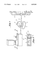
- FIG. 1 is a view of a ink jet apparatus
- FIG. 2 is a sectional view through one of the ink jet heads of FIG. 1 taken along the line 2--2;
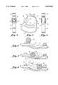
- FIG. 3 is a plan view of the hand gripped peristaltic pumping apparatus shown in FIG. 1;
- FIG. 4 is an end view of the peristaltic pumping apparatus of FIG. 3;
- FIG. 5 is another end view of the peristaltic pumping apparatus shown in FIG. 3;
- FIGS. 6 through 8 are schematic views of the peristaltic pumping apparatus shown in FIGS. 3-5 in various positions;
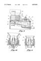
- FIG. 9 is a sectional view of the ink reservoir and supply of FIG. 1 taken along line 9--9;
- FIG. 10 is an enlarged sectional view of the ink supply mounted on the reservoir base as shown in FIG. 1;
- FIG. 11 is an enlarged sectional view of the ink supply prior to mounting on the reservoir base.
- an ink supply system comprising a reservoir 10, a peristaltic pumping apparatus 12, a manifold 14 and a plurality of impulse ink jets 16.
- the reservoir 10 is coupled to the manifold 14 by a flexible tube 18 which is coupled to the peristaltic pumping apparatus 12.
- Flexible tubes 20 couple the manifold to the various heads 16.
- Each of the heads 16 comprises a plurality of impulse ink jet devices 22 as shown in FIG. 2.
- the devices 22 are made in accordance with the disclosure of U.S. Pat. No. 4,459,601 which are incorporated herein by reference.
- a transducer 24 is coupled to an ink jet chamber 26 through a foot 27 having an orifice 28 for the ejection of droplets and an input opening 30 to which ink is supplied from the tubes 20 coupled to the manifold 14. Droplets are ejected on demand in response to the state of energization of the transducer 24 of the control of an electronic system. It will be appreciated that each of the heads 16 must be actually positioned above the uppermost level of ink in the reservoir 10 so as to avoid placing the ink under any sort of pressure head which would cause weeping from the orifices 28.
- a peristaltic pumping apparatus 12 is adapted to be gripped by hand with fingers being inserted through the elongated opening 32 and a pedestal 34 engaged by the palm or the base of the thumb.
- the apparatus 12 comprises the U-shaped structure 36 carrying a squeezing surface in the form of a roller 38 including caps 39 which is snapped into place at the end of one spring arm 40 and a support surface 42 which extends from a position adjacent the roller 38 to another spring arm 43 which is integrally formed with a base 44 in which the finger opening 32 is located.
- the base 44 includes an opening 46 through which the flexible tube 18 may extend when in contact with the support surface 42, and the base 44 also includes an opening 48 as shown in FIG. 5 including a lead-in 50 through which the tube 18 as shown in FIG. 1 may extend.
- the peristaltic pumping apparatus of FIGS. 3 through 5 When the peristaltic pumping apparatus of FIGS. 3 through 5 is actuated by application of hand pressure as described above, the squeezing surface on the roller 38 moves through a peristaltic pumping orbit so as to force ink through the flexible tube during a peristaltic pumping stroke when the pressure of the hand is removed so as to prevent sucking ink back through the tube 18 and the ink jet print head 16 shown in FIG. 1.
- the peristaltic pumping orbit may best be appreciated by reference to FIGS. 6 through 8 which will now be described in detail.
- the roller 38 is in the static position, i.e., before application of any hand pressure, and spaced from the tube 18.
- the roller 38 is moved along the tube 18 which is pressed against the support surface 42 and pressure is applied through the tube 18.
- the movement depicted in FIG. 7 is the peristaltic pumping stroke.
- the hand pressure is released and the roller 38 is automatically lifted off the tube 18 so as to permit the tube 18 to return to the decompressed position and the roller 38 is automatically moved back to the static position shown in FIG. 6.
- the movement of the roller 38 through the peristaltic pumping orbit is achieved by the spring arms 40 and 43.
- the spring 40 permits the roller 38 to advance along the surface 42 at an attack angle of no more than 45°.
- the spring arm 43 is biased to the point that upon release of the hand pressure, the roller moves away from the tube 18 as shown in FIG. 8 and returns to the static position as shown in FIG. 6.
- the peristaltic pumping apparatus 12 may be integrally formed from a variety of plastic materials to provide the appropriate characteristic including the necessary resilience for the springs 40 and 43.
- Nylon 6/6 is especially preferred.
- the ink reservoir 10 permits a relatively large supply of ink to be used while facilitating the priming in an efficient, ecologically sound and easy manner. More particularly, as best shown in FIG. 9, the reservoir 10 includes an ink supply base 52 including a cover 53 having a container support portion 54 and a level detect portion 56.
- the container support portion includes an opening 58 in the cover 53 which extends upwardly and is adapted to receive an ink supply apparatus including a closed container 60 as delivered to the base 52.
- Cover 53 further includes a shoulder portion 53' and a second opening 58', which as shown has a diameter that is smaller than the inner diameter of the neck and the diameter of the threaded periphery of the cap.
- a valve actuating means in the form of a projection 62 is located immediately below the opening 58 which is adapted to open the valve associated with the container 60 shown in FIG. 1 which will be described in more detail subsequently.
- the opening 58 is located in a neck 63 which extends upwardly from the cover 53 and includes threads 64 for receiving the delivered ink supply as best shown in FIGS. 9 and 10.
- the level detect portion 56 in the cover 53 includes a level detect mechanism 66 which is mounted on the cover 53.
- the mechanism 66 includes a float 68 which is free to move along the shaft 70, to the position shown in phantom which actuates a proximity switch so as to signal the level 73 of the ink within the reservoir formed by the base 52.
- the signal wires 76 are coupled to the proximity switch as shown.
- a washer 78 holds the float 68 on the shaft 70.
- a level detect device of this type is sold by Signal Systems International under the tradename FS2-B Liquid Level Switch.
- a port 80 in the base 52 is provided which may be coupled to the tube 18 as shown in FIG. 1.
- the port 80 may actually be located in a separate fitting.
- a vent opening 92 is also provided in the top of the cover 53 as shown or may be provided elsewhere for venting the reservoir hereby preventing an increase in pressure within the reservoir.
- a filter 93 is shown in base 52 adjacent the fitting 80 for filtering ink flowing to the ink jet device.
- a replaceable ink supply which is delivered to and mounted on the cover 53 comprises a valve mechanism which interrupts gravity feed of ink into the base 52.
- the ink supply comprises the container 60 having a neck 86 which is engaged by the threaded cap 88 terminated in a projection 89 having an opening 90 adapted to be aligned with the actuating member 62 in the base 52.
- a valve enclosure 92 is inserted into the neck 86 of the container 60 so as to enclose a plunger or valve member 94 in conjunction with the cap 88. As shown in FIG.
- the plunger member 94 is biased closed by the spring 96 which encircles a shaft 98 of the plunger member 94.
- the plunger member 94 is opened or unseated from the cap 88 by contact between the valve actuating member 62 and a concave actuating surface 100 of the plunger member 94.
- ink from the container 60 is permitted to flow upon mounting of the container 60 on the base 52 so as to create a reservoir of ink (outside the closed container 60 and the ink jet devices 16 without any extra steps on the part of the operator and without any leakage from the container 60.
- the container 60 may be readily refilled after removal from the base 52 by simply depressing plunger member 94 thereby providing an ecologically sound supply system.
- manifold 14 is optional and a single head 16 may be used with the peristaltic pumping apparatus 12. It will also be appreciated that the manifold 14 may be used with a plurality of peristaltic pumping apparatus 14, one for each tube 20.
Abstract
Description
Claims (22)
Priority Applications (3)
| Application Number | Priority Date | Filing Date | Title |
|---|---|---|---|
| US08/827,769 US6033061A (en) | 1990-09-28 | 1997-04-11 | Ink supply for impulse ink jet system, said ink supply including a cap having a threaded perphery, a valve supported by said cap and a projection for extending from the cap into an ink reservoir |
| US09/417,669 US6234617B1 (en) | 1990-09-28 | 1999-10-14 | Ink supply for impulse ink jet system, said ink supply including a cap having threaded periphery, and a valve supported by the cap, wherein a projection extends from a surface of the cap into an ink reservoir |
| US09/838,557 US6511154B2 (en) | 1990-09-28 | 2001-04-16 | Ink supply for impulse ink jet system, said ink supply including a cap having threaded periphery, and a valve supported by the cap, wherein a projection extends from a surface of the cap into an ink reservoir |
Applications Claiming Priority (3)
| Application Number | Priority Date | Filing Date | Title |
|---|---|---|---|
| US07/590,169 US5343226A (en) | 1990-09-28 | 1990-09-28 | Ink jet ink supply apparatus |
| US28288694A | 1994-07-29 | 1994-07-29 | |
| US08/827,769 US6033061A (en) | 1990-09-28 | 1997-04-11 | Ink supply for impulse ink jet system, said ink supply including a cap having a threaded perphery, a valve supported by said cap and a projection for extending from the cap into an ink reservoir |
Related Parent Applications (1)
| Application Number | Title | Priority Date | Filing Date |
|---|---|---|---|
| US28288694A Continuation | 1990-09-28 | 1994-07-29 |
Related Child Applications (1)
| Application Number | Title | Priority Date | Filing Date |
|---|---|---|---|
| US09/417,669 Continuation US6234617B1 (en) | 1990-09-28 | 1999-10-14 | Ink supply for impulse ink jet system, said ink supply including a cap having threaded periphery, and a valve supported by the cap, wherein a projection extends from a surface of the cap into an ink reservoir |
Publications (1)
| Publication Number | Publication Date |
|---|---|
| US6033061A true US6033061A (en) | 2000-03-07 |
Family
ID=24361152
Family Applications (4)
| Application Number | Title | Priority Date | Filing Date |
|---|---|---|---|
| US07/590,169 Expired - Lifetime US5343226A (en) | 1990-09-28 | 1990-09-28 | Ink jet ink supply apparatus |
| US08/827,769 Expired - Lifetime US6033061A (en) | 1990-09-28 | 1997-04-11 | Ink supply for impulse ink jet system, said ink supply including a cap having a threaded perphery, a valve supported by said cap and a projection for extending from the cap into an ink reservoir |
| US09/417,669 Expired - Fee Related US6234617B1 (en) | 1990-09-28 | 1999-10-14 | Ink supply for impulse ink jet system, said ink supply including a cap having threaded periphery, and a valve supported by the cap, wherein a projection extends from a surface of the cap into an ink reservoir |
| US09/838,557 Expired - Fee Related US6511154B2 (en) | 1990-09-28 | 2001-04-16 | Ink supply for impulse ink jet system, said ink supply including a cap having threaded periphery, and a valve supported by the cap, wherein a projection extends from a surface of the cap into an ink reservoir |
Family Applications Before (1)
| Application Number | Title | Priority Date | Filing Date |
|---|---|---|---|
| US07/590,169 Expired - Lifetime US5343226A (en) | 1990-09-28 | 1990-09-28 | Ink jet ink supply apparatus |
Family Applications After (2)
| Application Number | Title | Priority Date | Filing Date |
|---|---|---|---|
| US09/417,669 Expired - Fee Related US6234617B1 (en) | 1990-09-28 | 1999-10-14 | Ink supply for impulse ink jet system, said ink supply including a cap having threaded periphery, and a valve supported by the cap, wherein a projection extends from a surface of the cap into an ink reservoir |
| US09/838,557 Expired - Fee Related US6511154B2 (en) | 1990-09-28 | 2001-04-16 | Ink supply for impulse ink jet system, said ink supply including a cap having threaded periphery, and a valve supported by the cap, wherein a projection extends from a surface of the cap into an ink reservoir |
Country Status (1)
| Country | Link |
|---|---|
| US (4) | US5343226A (en) |
Cited By (12)
| Publication number | Priority date | Publication date | Assignee | Title |
|---|---|---|---|---|
| US6234617B1 (en) | 1990-09-28 | 2001-05-22 | Illinois Tool Works Inc. | Ink supply for impulse ink jet system, said ink supply including a cap having threaded periphery, and a valve supported by the cap, wherein a projection extends from a surface of the cap into an ink reservoir |
| FR2816241A1 (en) * | 2000-11-07 | 2002-05-10 | Segepar | NON-RETURN SYSTEM FOR INK SUPPLY CIRCUIT AND INK CARTRIDGE |
| US6637864B2 (en) | 2001-01-16 | 2003-10-28 | Eastman Kodak Company | Ink supply system for an ink jet printer |
| EP1380428A2 (en) * | 2002-07-09 | 2004-01-14 | Seiko Epson Corporation | Liquid cartridge and liquid accommodating member |
| US20040104959A1 (en) * | 2000-10-31 | 2004-06-03 | Brown Steven Robert | Printing apparatus |
| US20060164473A1 (en) * | 2005-01-21 | 2006-07-27 | Davis Jeremy A | Ink delivery system and methods for improved printing |
| US20060232644A1 (en) * | 2005-03-31 | 2006-10-19 | Heidelberger Druckmaschinen Ag | Ink jet device with individual shut-off |
| US20070188542A1 (en) * | 2006-02-03 | 2007-08-16 | Kanfoush Dan E | Apparatus and method for cleaning an inkjet printhead |
| US8888208B2 (en) | 2012-04-27 | 2014-11-18 | R.R. Donnelley & Sons Company | System and method for removing air from an inkjet cartridge and an ink supply line |
| US10124597B2 (en) | 2016-05-09 | 2018-11-13 | R.R. Donnelley & Sons Company | System and method for supplying ink to an inkjet printhead |
| US10137691B2 (en) | 2016-03-04 | 2018-11-27 | R.R. Donnelley & Sons Company | Printhead maintenance station and method of operating same |
| JP2018199301A (en) * | 2017-05-29 | 2018-12-20 | セーレン株式会社 | Liquid level detector and ink jet recorder |
Families Citing this family (62)
| Publication number | Priority date | Publication date | Assignee | Title |
|---|---|---|---|---|
| US5748216A (en) * | 1991-06-19 | 1998-05-05 | Hewlett-Packard Company | Inkjet print cartridge having valve connectable to an external ink reservoir for recharging the print cartridge |
| US5963238A (en) * | 1991-06-19 | 1999-10-05 | Hewlett-Packard Company | Intermittent refilling of print cartridge installed in an inkjet printer |
| US5777648A (en) * | 1991-06-19 | 1998-07-07 | Hewlett-Packard Company | Inkjet print cartridge having an ink fill port for initial filling and a recharge port with recloseable seal for recharging the print cartridge with ink |
| US5852458A (en) * | 1991-08-27 | 1998-12-22 | Hewlett-Packard Company | Inkjet print cartridge having a first inlet port for initial filling and a second inlet port for ink replenishment without removing the print cartridge from the printer |
| CA2100977C (en) * | 1992-07-24 | 2000-02-08 | Noribumi Koitabashi | Ink container, ink and ink jet recording apparatus using ink container |
| US6000791A (en) * | 1992-12-23 | 1999-12-14 | Hewlett-Packard Company | Printer having a removable print cartridge with handle incorporating an ink inlet value |
| US5675367A (en) * | 1992-12-23 | 1997-10-07 | Hewlett-Packard Company | Inkjet print cartridge having handle which incorporates an ink fill port |
| US5751320A (en) * | 1994-09-29 | 1998-05-12 | Hewlett-Packard Company | Ink recharger for inkjet print cartridge having sliding valve connectable to print cartridge |
| US5673073A (en) * | 1994-09-29 | 1997-09-30 | Hewlett-Packard Company | Syringe for filling print cartridge and establishing correct back pressure |
| JPH08174860A (en) * | 1994-10-26 | 1996-07-09 | Seiko Epson Corp | Ink cartridge for ink jet printer |
| CN1891470B (en) * | 1994-10-26 | 2011-03-02 | 精工爱普生株式会社 | Ink cartridge for ink-jet recording equipment and ink-jet recording equipment |
| US5825387A (en) * | 1995-04-27 | 1998-10-20 | Hewlett-Packard Company | Ink supply for an ink-jet printer |
| US5856839A (en) * | 1995-04-27 | 1999-01-05 | Hewlett-Packard Company | Ink supply having an integral pump |
| US5900896A (en) * | 1995-04-27 | 1999-05-04 | Hewlett-Packard Company | Ink cartridge adapters |
| US5771053A (en) | 1995-12-04 | 1998-06-23 | Hewlett-Packard Company | Assembly for controlling ink release from a container |
| US5900895A (en) | 1995-12-04 | 1999-05-04 | Hewlett-Packard Company | Method for refilling an ink supply for an ink-jet printer |
| US5815182A (en) | 1995-12-04 | 1998-09-29 | Hewlett-Packard Company | Fluid interconnect for ink-jet pen |
| US5732751A (en) | 1995-12-04 | 1998-03-31 | Hewlett-Packard Company | Filling ink supply containers |
| US5847734A (en) | 1995-12-04 | 1998-12-08 | Pawlowski, Jr.; Norman E. | Air purge system for an ink-jet printer |
| DE69733176T2 (en) | 1996-02-21 | 2006-02-16 | Seiko Epson Corp. | INK CARTRIDGE |
| US5903293A (en) * | 1996-05-20 | 1999-05-11 | Graphic Controls Corporation | Ink-jet bottle and valve system |
| JP4141523B2 (en) | 1997-03-19 | 2008-08-27 | セイコーエプソン株式会社 | Ink supply flow path valve device |
| US6079823A (en) * | 1997-07-23 | 2000-06-27 | Marconi Data Systems Inc. | Ink bottle with puncturable diaphragm closure |
| ATE386640T1 (en) * | 1998-07-15 | 2008-03-15 | Seiko Epson Corp | INK FEEDING DEVICE |
| DE69932395T2 (en) * | 1998-12-14 | 2007-07-19 | Eastman Kodak Co. | Fluid system for multiple printheads |
| US6164768A (en) * | 1999-11-09 | 2000-12-26 | Illinois Tool Works Inc. | Adapter and mating bottle cap for coupling bottles to ink supplies |
| US20020118259A1 (en) * | 2000-03-29 | 2002-08-29 | Ranganathan Nadeepuram Kuppanna | Inking system and method |
| MY141858A (en) * | 2000-10-20 | 2010-07-16 | Seiko Epson Corp | Ink cartridge for ink jet recording device |
| PT1481807E (en) * | 2000-10-20 | 2007-02-28 | Seiko Epson Corp | Ink jet recording device and ink cartridge |
| EP1481807B2 (en) * | 2000-10-20 | 2010-11-10 | Seiko Epson Corporation | Ink jet recording device and ink cartridge |
| US6402309B1 (en) | 2001-03-05 | 2002-06-11 | Inkjet, Inc. | Magnetically activated valve for ink |
| US6737042B2 (en) * | 2001-05-24 | 2004-05-18 | Alexza Molecular Delivery Corporation | Delivery of drug esters through an inhalation route |
| JP3991853B2 (en) * | 2002-09-12 | 2007-10-17 | セイコーエプソン株式会社 | ink cartridge |
| US20050015297A1 (en) * | 2003-07-01 | 2005-01-20 | Basf Drucksysteme Gmbh | Marketing of photopolymeric sleeves for flexographic printing |
| US7300138B2 (en) * | 2004-01-08 | 2007-11-27 | Eastman Kodak Company | Replaceable ink container for inkjet printer |
| CN101027187B (en) * | 2004-01-09 | 2011-07-06 | 录象射流技术公司 | System and method for connecting an ink bottle to an ink reservoir of an ink jet printing system |
| US7543920B2 (en) * | 2004-01-09 | 2009-06-09 | Videojet Technologies Inc. | System and method for connecting an ink bottle to an ink reservoir of an ink jet printing system |
| GB2412088B (en) * | 2004-03-19 | 2007-09-19 | Zipher Ltd | Liquid supply system |
| US7281785B2 (en) * | 2004-09-17 | 2007-10-16 | Fujifilm Dimatix, Inc. | Fluid handling in droplet deposition systems |
| WO2007021700A2 (en) * | 2005-08-10 | 2007-02-22 | Markem Corporation | Printing devices and related devices and methods |
| WO2007021740A2 (en) * | 2005-08-10 | 2007-02-22 | Markem Corporation | Ink supply system |
| JP4815972B2 (en) * | 2005-09-28 | 2011-11-16 | 日産自動車株式会社 | Leak diagnostic device for evaporative fuel processing system |
| US7810916B2 (en) * | 2005-09-29 | 2010-10-12 | Brother Kogyo Kabushiki Kaisha | Ink cartridges |
| US7553007B2 (en) * | 2005-09-29 | 2009-06-30 | Brother Kogyo Kabushiki Kaisha | Ink cartridges |
| JP4857848B2 (en) * | 2006-03-24 | 2012-01-18 | ブラザー工業株式会社 | ink cartridge |
| US7661803B2 (en) * | 2006-07-31 | 2010-02-16 | Silverbrook Research Pty Ltd | Inkjet printhead with controlled de-prime |
| DE102007001084A1 (en) * | 2006-12-12 | 2008-06-19 | Pelikan Hardcopy Production Ag | Ink cartridge, for mounting below) inkjet on printing head of ink jet printer, has vent aperture with valve coupled to valve on ink outlet, both valves opening automatically when cartridge is inserted |
| DK200900030U4 (en) * | 2009-02-09 | 2010-05-28 | Masytec As | Automatic color filling system |
| US20110025786A1 (en) * | 2009-07-29 | 2011-02-03 | Price Brian G | Ink reservoir with a biasing valve |
| US20110025765A1 (en) | 2009-07-31 | 2011-02-03 | Silverbrook Research Pty Ltd | Printing system with datum features on printhead carriage |
| US8833919B2 (en) * | 2010-05-17 | 2014-09-16 | Memjet Technology Ltd. | Method of shaping media at printhead |
| US8529028B2 (en) | 2010-05-17 | 2013-09-10 | Zamtec Ltd | Fluid distribution system having printhead bypass from container |
| US20110279615A1 (en) | 2010-05-17 | 2011-11-17 | Silverbrook Research Pty Ltd | Drive belt tensioning apparatus for printer |
| US10184057B2 (en) | 2011-03-01 | 2019-01-22 | Thomas Villwock | Nanoparticle suspension for inkjet printing magnetizable characters on a substrate |
| JP6127387B2 (en) * | 2012-06-04 | 2017-05-17 | セイコーエプソン株式会社 | Ink bottle for ink ejector |
| CN108136787B (en) * | 2015-08-28 | 2019-02-01 | T·威尔沃克 | Fluid delivery system for ink-jet printer |
| US11640615B2 (en) | 2016-09-08 | 2023-05-02 | Thomas Villwock | Methods and systems for authenticating goods and services using electronic analysis of analyte encoded compositions |
| JP6907559B2 (en) | 2017-01-26 | 2021-07-21 | セイコーエプソン株式会社 | Ink bottle |
| JP6926493B2 (en) * | 2017-01-31 | 2021-08-25 | ブラザー工業株式会社 | Image recording device |
| US10315814B2 (en) * | 2017-08-04 | 2019-06-11 | Canon Kabushiki Kaisha | Transfer cap |
| JP7183777B2 (en) | 2018-12-25 | 2022-12-06 | ブラザー工業株式会社 | liquid supply system |
| US11220967B1 (en) | 2020-10-06 | 2022-01-11 | Garrett Transportation I, Inc. | Mass flow measurement system using adaptive calibration and sensor diagnostics |
Citations (28)
| Publication number | Priority date | Publication date | Assignee | Title |
|---|---|---|---|---|
| US3805276A (en) * | 1971-12-25 | 1974-04-16 | Casio Computer Co Ltd | Ink jet recording apparatus |
| US3930761A (en) * | 1972-12-19 | 1976-01-06 | The Boots Company, Ltd. | Portable and manually operable peristaltic pump |
| US3944844A (en) * | 1972-06-12 | 1976-03-16 | Ronald Trist Controls Limited | Float operated electrical switch assembly |
| US3974508A (en) * | 1974-12-16 | 1976-08-10 | Gould Inc. | Air purging system for a pulsed droplet ejecting system |
| US4123761A (en) * | 1976-06-07 | 1978-10-31 | Konishiroku Photo Industry Co., Ltd. | Method of purging ink passages of an ink jet recording device |
| US4162501A (en) * | 1977-08-08 | 1979-07-24 | Silonics, Inc. | Ink supply system for an ink jet printer |
| US4170016A (en) * | 1977-12-12 | 1979-10-02 | Gould Inc. | Priming apparatus for liquid ink writing instruments |
| US4183031A (en) * | 1976-06-07 | 1980-01-08 | Silonics, Inc. | Ink supply system |
| US4240082A (en) * | 1979-02-28 | 1980-12-16 | The Mead Corporation | Momentumless shutdown of a jet drop recorder |
| US4333088A (en) * | 1980-11-03 | 1982-06-01 | Exxon Research & Engineering Co. | Disposable peristaltic pump assembly for facsimile printer |
| US4359744A (en) * | 1980-11-03 | 1982-11-16 | Exxon Research And Engineering Co. | Ink jet printer with peristaltic pump |
| US4364065A (en) * | 1979-08-13 | 1982-12-14 | Matsushita Electric Industrial Company, Limited | Ink jet writing apparatus having a nozzle moistening device |
| US4376283A (en) * | 1980-11-03 | 1983-03-08 | Exxon Research And Engineering Co. | Method and apparatus for using a disposable ink jet assembly in a facsimile system and the like |
| US4380770A (en) * | 1979-11-22 | 1983-04-19 | Epson Corporation | Ink jet printer |
| JPS58107349A (en) * | 1981-12-19 | 1983-06-27 | Ricoh Co Ltd | Bottle fixing device |
| US4424521A (en) * | 1982-01-04 | 1984-01-03 | Exxon Research And Engineering Co. | Ink jet apparatus and reservoir |
| US4459601A (en) * | 1981-01-30 | 1984-07-10 | Exxon Research And Engineering Co. | Ink jet method and apparatus |
| US4517577A (en) * | 1983-02-10 | 1985-05-14 | Exxon Research And Engineering Co. | Method of and apparatus for priming an ink jet |
| US4536777A (en) * | 1983-04-21 | 1985-08-20 | Canon Kabushiki Kaisha | Liquid jet recording apparatus |
| US4593294A (en) * | 1985-04-22 | 1986-06-03 | Exxon Printing Systems, Inc. | Ink jet method and apparatus |
| US4626874A (en) * | 1984-07-06 | 1986-12-02 | Ricoh Company, Ltd. | Liquid level detector for ink jet printer |
| US4700202A (en) * | 1983-02-23 | 1987-10-13 | Sharp Kabushiki Kaisha | Ink cartridge in an ink jet system printer |
| US4716422A (en) * | 1985-08-12 | 1987-12-29 | Siemens Aktiengesellschaft | Mechanism for rinsing an ink printing head |
| JPS633959A (en) * | 1986-06-24 | 1988-01-08 | Canon Inc | Ink supply device |
| US4831389A (en) * | 1987-12-21 | 1989-05-16 | Hewlett-Packard Company | Off board ink supply system and process for operating an ink jet printer |
| US4946075A (en) * | 1989-06-29 | 1990-08-07 | Unro Teknik Ab | Device for dispensing flowing substances |
| US5055856A (en) * | 1988-09-07 | 1991-10-08 | Seiko Epson Corporation | Capping device for ink jet printers |
| US5343226A (en) * | 1990-09-28 | 1994-08-30 | Dataproducts Corporation | Ink jet ink supply apparatus |
-
1990
- 1990-09-28 US US07/590,169 patent/US5343226A/en not_active Expired - Lifetime
-
1997
- 1997-04-11 US US08/827,769 patent/US6033061A/en not_active Expired - Lifetime
-
1999
- 1999-10-14 US US09/417,669 patent/US6234617B1/en not_active Expired - Fee Related
-
2001
- 2001-04-16 US US09/838,557 patent/US6511154B2/en not_active Expired - Fee Related
Patent Citations (28)
| Publication number | Priority date | Publication date | Assignee | Title |
|---|---|---|---|---|
| US3805276A (en) * | 1971-12-25 | 1974-04-16 | Casio Computer Co Ltd | Ink jet recording apparatus |
| US3944844A (en) * | 1972-06-12 | 1976-03-16 | Ronald Trist Controls Limited | Float operated electrical switch assembly |
| US3930761A (en) * | 1972-12-19 | 1976-01-06 | The Boots Company, Ltd. | Portable and manually operable peristaltic pump |
| US3974508A (en) * | 1974-12-16 | 1976-08-10 | Gould Inc. | Air purging system for a pulsed droplet ejecting system |
| US4183031A (en) * | 1976-06-07 | 1980-01-08 | Silonics, Inc. | Ink supply system |
| US4123761A (en) * | 1976-06-07 | 1978-10-31 | Konishiroku Photo Industry Co., Ltd. | Method of purging ink passages of an ink jet recording device |
| US4162501A (en) * | 1977-08-08 | 1979-07-24 | Silonics, Inc. | Ink supply system for an ink jet printer |
| US4170016A (en) * | 1977-12-12 | 1979-10-02 | Gould Inc. | Priming apparatus for liquid ink writing instruments |
| US4240082A (en) * | 1979-02-28 | 1980-12-16 | The Mead Corporation | Momentumless shutdown of a jet drop recorder |
| US4364065A (en) * | 1979-08-13 | 1982-12-14 | Matsushita Electric Industrial Company, Limited | Ink jet writing apparatus having a nozzle moistening device |
| US4380770A (en) * | 1979-11-22 | 1983-04-19 | Epson Corporation | Ink jet printer |
| US4333088A (en) * | 1980-11-03 | 1982-06-01 | Exxon Research & Engineering Co. | Disposable peristaltic pump assembly for facsimile printer |
| US4359744A (en) * | 1980-11-03 | 1982-11-16 | Exxon Research And Engineering Co. | Ink jet printer with peristaltic pump |
| US4376283A (en) * | 1980-11-03 | 1983-03-08 | Exxon Research And Engineering Co. | Method and apparatus for using a disposable ink jet assembly in a facsimile system and the like |
| US4459601A (en) * | 1981-01-30 | 1984-07-10 | Exxon Research And Engineering Co. | Ink jet method and apparatus |
| JPS58107349A (en) * | 1981-12-19 | 1983-06-27 | Ricoh Co Ltd | Bottle fixing device |
| US4424521A (en) * | 1982-01-04 | 1984-01-03 | Exxon Research And Engineering Co. | Ink jet apparatus and reservoir |
| US4517577A (en) * | 1983-02-10 | 1985-05-14 | Exxon Research And Engineering Co. | Method of and apparatus for priming an ink jet |
| US4700202A (en) * | 1983-02-23 | 1987-10-13 | Sharp Kabushiki Kaisha | Ink cartridge in an ink jet system printer |
| US4536777A (en) * | 1983-04-21 | 1985-08-20 | Canon Kabushiki Kaisha | Liquid jet recording apparatus |
| US4626874A (en) * | 1984-07-06 | 1986-12-02 | Ricoh Company, Ltd. | Liquid level detector for ink jet printer |
| US4593294A (en) * | 1985-04-22 | 1986-06-03 | Exxon Printing Systems, Inc. | Ink jet method and apparatus |
| US4716422A (en) * | 1985-08-12 | 1987-12-29 | Siemens Aktiengesellschaft | Mechanism for rinsing an ink printing head |
| JPS633959A (en) * | 1986-06-24 | 1988-01-08 | Canon Inc | Ink supply device |
| US4831389A (en) * | 1987-12-21 | 1989-05-16 | Hewlett-Packard Company | Off board ink supply system and process for operating an ink jet printer |
| US5055856A (en) * | 1988-09-07 | 1991-10-08 | Seiko Epson Corporation | Capping device for ink jet printers |
| US4946075A (en) * | 1989-06-29 | 1990-08-07 | Unro Teknik Ab | Device for dispensing flowing substances |
| US5343226A (en) * | 1990-09-28 | 1994-08-30 | Dataproducts Corporation | Ink jet ink supply apparatus |
Cited By (23)
| Publication number | Priority date | Publication date | Assignee | Title |
|---|---|---|---|---|
| US6511154B2 (en) | 1990-09-28 | 2003-01-28 | Illinois Tool Works, Inc. | Ink supply for impulse ink jet system, said ink supply including a cap having threaded periphery, and a valve supported by the cap, wherein a projection extends from a surface of the cap into an ink reservoir |
| US6234617B1 (en) | 1990-09-28 | 2001-05-22 | Illinois Tool Works Inc. | Ink supply for impulse ink jet system, said ink supply including a cap having threaded periphery, and a valve supported by the cap, wherein a projection extends from a surface of the cap into an ink reservoir |
| US7419239B2 (en) | 2000-10-31 | 2008-09-02 | Zipher Limited | Printing apparatus |
| US20040104959A1 (en) * | 2000-10-31 | 2004-06-03 | Brown Steven Robert | Printing apparatus |
| FR2816241A1 (en) * | 2000-11-07 | 2002-05-10 | Segepar | NON-RETURN SYSTEM FOR INK SUPPLY CIRCUIT AND INK CARTRIDGE |
| EP1205309A1 (en) * | 2000-11-07 | 2002-05-15 | Segepar | Anti-reverse system for ink feeding circuit and ink cartridge |
| US6637864B2 (en) | 2001-01-16 | 2003-10-28 | Eastman Kodak Company | Ink supply system for an ink jet printer |
| EP1380428A2 (en) * | 2002-07-09 | 2004-01-14 | Seiko Epson Corporation | Liquid cartridge and liquid accommodating member |
| US20040056934A1 (en) * | 2002-07-09 | 2004-03-25 | Takeo Seino | Liquid cartridge and liquid accommodating member |
| EP1380428A3 (en) * | 2002-07-09 | 2004-07-28 | Seiko Epson Corporation | Liquid cartridge and liquid accommodating member |
| US6843558B2 (en) | 2002-07-09 | 2005-01-18 | Seiko Epson Corporation | Liquid cartridge and liquid accommodating member |
| US20060164473A1 (en) * | 2005-01-21 | 2006-07-27 | Davis Jeremy A | Ink delivery system and methods for improved printing |
| US20090058956A1 (en) * | 2005-01-21 | 2009-03-05 | Davis Jeremy A | Ink delivery system and methods for improved printing |
| US7510274B2 (en) | 2005-01-21 | 2009-03-31 | Hewlett-Packard Development Company, L.P. | Ink delivery system and methods for improved printing |
| US7997698B2 (en) | 2005-01-21 | 2011-08-16 | Hewlett-Packard Development Company, L.P. | Ink delivery system and methods for improved printing |
| US20060232644A1 (en) * | 2005-03-31 | 2006-10-19 | Heidelberger Druckmaschinen Ag | Ink jet device with individual shut-off |
| US7621625B2 (en) * | 2005-03-31 | 2009-11-24 | Heidelberger Druckmaschinen Ag | Ink jet device with individual shut-off |
| US20070188542A1 (en) * | 2006-02-03 | 2007-08-16 | Kanfoush Dan E | Apparatus and method for cleaning an inkjet printhead |
| US7918530B2 (en) | 2006-02-03 | 2011-04-05 | Rr Donnelley | Apparatus and method for cleaning an inkjet printhead |
| US8888208B2 (en) | 2012-04-27 | 2014-11-18 | R.R. Donnelley & Sons Company | System and method for removing air from an inkjet cartridge and an ink supply line |
| US10137691B2 (en) | 2016-03-04 | 2018-11-27 | R.R. Donnelley & Sons Company | Printhead maintenance station and method of operating same |
| US10124597B2 (en) | 2016-05-09 | 2018-11-13 | R.R. Donnelley & Sons Company | System and method for supplying ink to an inkjet printhead |
| JP2018199301A (en) * | 2017-05-29 | 2018-12-20 | セーレン株式会社 | Liquid level detector and ink jet recorder |
Also Published As
| Publication number | Publication date |
|---|---|
| US5343226A (en) | 1994-08-30 |
| US6511154B2 (en) | 2003-01-28 |
| US20010013882A1 (en) | 2001-08-16 |
| US6234617B1 (en) | 2001-05-22 |
Similar Documents
| Publication | Publication Date | Title |
|---|---|---|
| US6033061A (en) | Ink supply for impulse ink jet system, said ink supply including a cap having a threaded perphery, a valve supported by said cap and a projection for extending from the cap into an ink reservoir | |
| EP0814913B1 (en) | Pump sprayer | |
| US4175704A (en) | Non-aerosol continuous spray dispenser | |
| US4067499A (en) | Non-aerosol continuous spray dispenser | |
| US7543923B2 (en) | Liquid supply system | |
| US4958754A (en) | Dispenser or sprayer with vent system | |
| US5646666A (en) | Back pressure control in ink-jet printing | |
| JP2660561B2 (en) | Discharge device | |
| US4260082A (en) | Manually operated liquid dispensing device | |
| US3478935A (en) | Dispensing device | |
| GB1562817A (en) | Trigger type spraying device | |
| JPH0849649A (en) | Pump and distributor with said pump | |
| DK174266B1 (en) | Device for spraying material out of a container | |
| US4170016A (en) | Priming apparatus for liquid ink writing instruments | |
| SE443743B (en) | INSTRUMENT PRINTERS AND WAY TO STOP A INSTRUMENT PRINTER | |
| US5624059A (en) | Device for dispensing corrosive liquids accurately and without contamination | |
| JPH10137642A (en) | Sprayer | |
| EP0691161A1 (en) | A device for dispensing pastes or liquids from bottles or the like | |
| JPS60151054A (en) | Capping device | |
| US4602726A (en) | Dispensing device | |
| JPH05104041A (en) | Liquid dripping preventing device of sprayer | |
| KR930007514A (en) | Spray | |
| US4305701A (en) | Priming apparatus for liquid ink writing instruments | |
| JP2001253093A (en) | Ink jet recorder | |
| JP2002273279A (en) | Pressure accumulation type liquid spray unit |
Legal Events
| Date | Code | Title | Description |
|---|---|---|---|
| AS | Assignment |
Owner name: DATAPRODUCTS CORPORATION, CALIFORNIA Free format text: CROSS-REFERENCE OF ASSIGNMENT ORIGINALLY RECORDED IN S.N. 07/590,169 AT REEL 7061, FRAME(S) 0597.;ASSIGNORS:ROGERS, ROBERT;NIEDERMEYER, JOHN F.;MALTSEV, VIACHESLAV B.;REEL/FRAME:008509/0853 Effective date: 19940506 |
|
| STCF | Information on status: patent grant |
Free format text: PATENTED CASE |
|
| AS | Assignment |
Owner name: ILLINOIS TOOL WORKS INC., ILLINOIS Free format text: ASSIGNMENT OF ASSIGNORS INTEREST;ASSIGNOR:HITACHI IMAGING SOLUTIONS, INC.;REEL/FRAME:011333/0975 Effective date: 20001005 Owner name: ILLINOIS TOOL WORKS INC., ILLINOIS Free format text: ASSIGNMENT OF ASSIGNORS INTEREST;ASSIGNOR:HITACHI KOKI IMAGING SOLUTIONS, INC.(FORMERLY DATAPRODUCTS CORPORATION);REEL/FRAME:011379/0079 Effective date: 20001018 |
|
| AS | Assignment |
Owner name: ILLINOIS TOOL WORKS INC., ILLINOIS Free format text: ASSIGNMENT OF ASSIGNORS INTEREST;ASSIGNOR:HITACHI KOKI IMAGING SOLUTIONS, INC. (FORMERLY DATAPRODUCTS CORPORATION);REEL/FRAME:011511/0397 Effective date: 20001005 |
|
| REMI | Maintenance fee reminder mailed | ||
| FEPP | Fee payment procedure |
Free format text: PETITION RELATED TO MAINTENANCE FEES FILED (ORIGINAL EVENT CODE: PMFP); ENTITY STATUS OF PATENT OWNER: LARGE ENTITY |
|
| REIN | Reinstatement after maintenance fee payment confirmed | ||
| FP | Lapsed due to failure to pay maintenance fee |
Effective date: 20040307 |
|
| FPAY | Fee payment |
Year of fee payment: 4 |
|
| PRDP | Patent reinstated due to the acceptance of a late maintenance fee |
Effective date: 20040526 |
|
| FPAY | Fee payment |
Year of fee payment: 8 |
|
| REMI | Maintenance fee reminder mailed | ||
| FPAY | Fee payment |
Year of fee payment: 12 |