US6034323A - Solar cell module - Google Patents
Solar cell module Download PDFInfo
- Publication number
- US6034323A US6034323A US09/024,863 US2486398A US6034323A US 6034323 A US6034323 A US 6034323A US 2486398 A US2486398 A US 2486398A US 6034323 A US6034323 A US 6034323A
- Authority
- US
- United States
- Prior art keywords
- solar cell
- support member
- cell module
- protective film
- sealing material
- Prior art date
- Legal status (The legal status is an assumption and is not a legal conclusion. Google has not performed a legal analysis and makes no representation as to the accuracy of the status listed.)
- Expired - Lifetime
Links
- 239000003566 sealing material Substances 0.000 claims abstract description 57
- 230000001681 protective effect Effects 0.000 claims abstract description 44
- 238000000034 method Methods 0.000 claims description 23
- 239000000463 material Substances 0.000 claims description 14
- 238000003475 lamination Methods 0.000 claims description 13
- 239000011521 glass Substances 0.000 claims description 11
- 239000004065 semiconductor Substances 0.000 claims description 10
- 229910052751 metal Inorganic materials 0.000 claims description 8
- 239000002184 metal Substances 0.000 claims description 8
- 239000003365 glass fiber Substances 0.000 claims description 5
- 229920003023 plastic Polymers 0.000 claims description 4
- 239000004033 plastic Substances 0.000 claims description 4
- 238000007789 sealing Methods 0.000 claims description 4
- 239000000835 fiber Substances 0.000 claims description 3
- 238000007731 hot pressing Methods 0.000 claims description 3
- 238000010248 power generation Methods 0.000 claims description 3
- 239000004677 Nylon Substances 0.000 claims description 2
- 239000011152 fibreglass Substances 0.000 claims description 2
- 229920001778 nylon Polymers 0.000 claims description 2
- 239000005020 polyethylene terephthalate Substances 0.000 claims description 2
- 238000005452 bending Methods 0.000 claims 1
- 229910021421 monocrystalline silicon Inorganic materials 0.000 claims 1
- 229910000831 Steel Inorganic materials 0.000 abstract description 14
- 239000010959 steel Substances 0.000 abstract description 14
- JEIPFZHSYJVQDO-UHFFFAOYSA-N iron(III) oxide Inorganic materials O=[Fe]O[Fe]=O JEIPFZHSYJVQDO-UHFFFAOYSA-N 0.000 abstract description 13
- 230000002265 prevention Effects 0.000 abstract description 4
- 239000010408 film Substances 0.000 description 48
- 206010040844 Skin exfoliation Diseases 0.000 description 33
- 238000011156 evaluation Methods 0.000 description 15
- 239000000853 adhesive Substances 0.000 description 13
- 230000001070 adhesive effect Effects 0.000 description 13
- 239000000758 substrate Substances 0.000 description 12
- 150000003839 salts Chemical class 0.000 description 10
- 229920005989 resin Polymers 0.000 description 9
- 239000011347 resin Substances 0.000 description 9
- 239000007921 spray Substances 0.000 description 9
- 239000004745 nonwoven fabric Substances 0.000 description 8
- 229910021417 amorphous silicon Inorganic materials 0.000 description 6
- XLYOFNOQVPJJNP-UHFFFAOYSA-N water Substances O XLYOFNOQVPJJNP-UHFFFAOYSA-N 0.000 description 6
- RYGMFSIKBFXOCR-UHFFFAOYSA-N Copper Chemical compound [Cu] RYGMFSIKBFXOCR-UHFFFAOYSA-N 0.000 description 5
- 239000006096 absorbing agent Substances 0.000 description 5
- 229910052782 aluminium Inorganic materials 0.000 description 5
- 239000011248 coating agent Substances 0.000 description 5
- 238000000576 coating method Methods 0.000 description 5
- 238000010438 heat treatment Methods 0.000 description 5
- 238000004544 sputter deposition Methods 0.000 description 5
- XOLBLPGZBRYERU-UHFFFAOYSA-N tin dioxide Chemical compound O=[Sn]=O XOLBLPGZBRYERU-UHFFFAOYSA-N 0.000 description 5
- BLRPTPMANUNPDV-UHFFFAOYSA-N Silane Chemical compound [SiH4] BLRPTPMANUNPDV-UHFFFAOYSA-N 0.000 description 4
- GWEVSGVZZGPLCZ-UHFFFAOYSA-N Titan oxide Chemical compound O=[Ti]=O GWEVSGVZZGPLCZ-UHFFFAOYSA-N 0.000 description 4
- XAGFODPZIPBFFR-UHFFFAOYSA-N aluminium Chemical compound [Al] XAGFODPZIPBFFR-UHFFFAOYSA-N 0.000 description 4
- 238000011109 contamination Methods 0.000 description 4
- 229910052802 copper Inorganic materials 0.000 description 4
- 239000010949 copper Substances 0.000 description 4
- 230000000694 effects Effects 0.000 description 4
- 229920000840 ethylene tetrafluoroethylene copolymer Polymers 0.000 description 4
- 238000004299 exfoliation Methods 0.000 description 4
- 238000004519 manufacturing process Methods 0.000 description 4
- 229910044991 metal oxide Inorganic materials 0.000 description 4
- 239000004590 silicone sealant Substances 0.000 description 4
- 229910052709 silver Inorganic materials 0.000 description 4
- 229910001220 stainless steel Inorganic materials 0.000 description 4
- 239000010935 stainless steel Substances 0.000 description 4
- 238000007740 vapor deposition Methods 0.000 description 4
- 229920002430 Fibre-reinforced plastic Polymers 0.000 description 3
- BQCADISMDOOEFD-UHFFFAOYSA-N Silver Chemical compound [Ag] BQCADISMDOOEFD-UHFFFAOYSA-N 0.000 description 3
- 238000006243 chemical reaction Methods 0.000 description 3
- 230000000052 comparative effect Effects 0.000 description 3
- 239000005038 ethylene vinyl acetate Substances 0.000 description 3
- 239000011151 fibre-reinforced plastic Substances 0.000 description 3
- 238000009413 insulation Methods 0.000 description 3
- 239000000203 mixture Substances 0.000 description 3
- PXHVJJICTQNCMI-UHFFFAOYSA-N nickel Substances [Ni] PXHVJJICTQNCMI-UHFFFAOYSA-N 0.000 description 3
- 229920001200 poly(ethylene-vinyl acetate) Polymers 0.000 description 3
- -1 polychlorotrifluoroethylene Polymers 0.000 description 3
- 229920002050 silicone resin Polymers 0.000 description 3
- 239000004332 silver Substances 0.000 description 3
- 239000004925 Acrylic resin Substances 0.000 description 2
- 229920000178 Acrylic resin Polymers 0.000 description 2
- 229920002799 BoPET Polymers 0.000 description 2
- OKTJSMMVPCPJKN-UHFFFAOYSA-N Carbon Chemical compound [C] OKTJSMMVPCPJKN-UHFFFAOYSA-N 0.000 description 2
- 229910004613 CdTe Inorganic materials 0.000 description 2
- 229910001335 Galvanized steel Inorganic materials 0.000 description 2
- XEEYBQQBJWHFJM-UHFFFAOYSA-N Iron Chemical compound [Fe] XEEYBQQBJWHFJM-UHFFFAOYSA-N 0.000 description 2
- XUIMIQQOPSSXEZ-UHFFFAOYSA-N Silicon Chemical compound [Si] XUIMIQQOPSSXEZ-UHFFFAOYSA-N 0.000 description 2
- 239000004809 Teflon Substances 0.000 description 2
- 229920006362 Teflon® Polymers 0.000 description 2
- RTAQQCXQSZGOHL-UHFFFAOYSA-N Titanium Chemical compound [Ti] RTAQQCXQSZGOHL-UHFFFAOYSA-N 0.000 description 2
- XLOMVQKBTHCTTD-UHFFFAOYSA-N Zinc monoxide Chemical compound [Zn]=O XLOMVQKBTHCTTD-UHFFFAOYSA-N 0.000 description 2
- 239000011230 binding agent Substances 0.000 description 2
- 229910052799 carbon Inorganic materials 0.000 description 2
- 150000001875 compounds Chemical class 0.000 description 2
- 229920001577 copolymer Polymers 0.000 description 2
- 238000004132 cross linking Methods 0.000 description 2
- 238000001035 drying Methods 0.000 description 2
- 238000001704 evaporation Methods 0.000 description 2
- 239000008397 galvanized steel Substances 0.000 description 2
- 238000007602 hot air drying Methods 0.000 description 2
- 239000012535 impurity Substances 0.000 description 2
- 238000002844 melting Methods 0.000 description 2
- 230000008018 melting Effects 0.000 description 2
- 229910021424 microcrystalline silicon Inorganic materials 0.000 description 2
- 229910052750 molybdenum Inorganic materials 0.000 description 2
- 229910052759 nickel Inorganic materials 0.000 description 2
- QUAMTGJKVDWJEQ-UHFFFAOYSA-N octabenzone Chemical compound OC1=CC(OCCCCCCCC)=CC=C1C(=O)C1=CC=CC=C1 QUAMTGJKVDWJEQ-UHFFFAOYSA-N 0.000 description 2
- 238000009832 plasma treatment Methods 0.000 description 2
- 238000000623 plasma-assisted chemical vapour deposition Methods 0.000 description 2
- 229910021420 polycrystalline silicon Inorganic materials 0.000 description 2
- 229920000642 polymer Polymers 0.000 description 2
- 229920002620 polyvinyl fluoride Polymers 0.000 description 2
- 238000007650 screen-printing Methods 0.000 description 2
- 229910052710 silicon Inorganic materials 0.000 description 2
- 239000010703 silicon Substances 0.000 description 2
- 229920002379 silicone rubber Polymers 0.000 description 2
- 239000004945 silicone rubber Substances 0.000 description 2
- 229910000679 solder Inorganic materials 0.000 description 2
- 239000010936 titanium Substances 0.000 description 2
- 229910052719 titanium Inorganic materials 0.000 description 2
- 229910052721 tungsten Inorganic materials 0.000 description 2
- 238000003466 welding Methods 0.000 description 2
- 238000009736 wetting Methods 0.000 description 2
- DMWVYCCGCQPJEA-UHFFFAOYSA-N 2,5-bis(tert-butylperoxy)-2,5-dimethylhexane Chemical compound CC(C)(C)OOC(C)(C)CCC(C)(C)OOC(C)(C)C DMWVYCCGCQPJEA-UHFFFAOYSA-N 0.000 description 1
- 229920001780 ECTFE Polymers 0.000 description 1
- 239000004593 Epoxy Substances 0.000 description 1
- JOYRKODLDBILNP-UHFFFAOYSA-N Ethyl urethane Chemical compound CCOC(N)=O JOYRKODLDBILNP-UHFFFAOYSA-N 0.000 description 1
- 229910001218 Gallium arsenide Inorganic materials 0.000 description 1
- ZOKXTWBITQBERF-UHFFFAOYSA-N Molybdenum Chemical compound [Mo] ZOKXTWBITQBERF-UHFFFAOYSA-N 0.000 description 1
- CBENFWSGALASAD-UHFFFAOYSA-N Ozone Chemical compound [O-][O+]=O CBENFWSGALASAD-UHFFFAOYSA-N 0.000 description 1
- 239000002033 PVDF binder Substances 0.000 description 1
- 239000006087 Silane Coupling Agent Substances 0.000 description 1
- IDCBOTIENDVCBQ-UHFFFAOYSA-N TEPP Chemical compound CCOP(=O)(OCC)OP(=O)(OCC)OCC IDCBOTIENDVCBQ-UHFFFAOYSA-N 0.000 description 1
- 229920006355 Tefzel Polymers 0.000 description 1
- XTXRWKRVRITETP-UHFFFAOYSA-N Vinyl acetate Chemical compound CC(=O)OC=C XTXRWKRVRITETP-UHFFFAOYSA-N 0.000 description 1
- NIXOWILDQLNWCW-UHFFFAOYSA-N acrylic acid group Chemical group C(C=C)(=O)O NIXOWILDQLNWCW-UHFFFAOYSA-N 0.000 description 1
- 239000004840 adhesive resin Substances 0.000 description 1
- 229920006223 adhesive resin Polymers 0.000 description 1
- 239000002390 adhesive tape Substances 0.000 description 1
- 229920000180 alkyd Polymers 0.000 description 1
- 239000003963 antioxidant agent Substances 0.000 description 1
- 230000003078 antioxidant effect Effects 0.000 description 1
- 239000012298 atmosphere Substances 0.000 description 1
- 239000011324 bead Substances 0.000 description 1
- DQXBYHZEEUGOBF-UHFFFAOYSA-N but-3-enoic acid;ethene Chemical compound C=C.OC(=O)CC=C DQXBYHZEEUGOBF-UHFFFAOYSA-N 0.000 description 1
- 229910010293 ceramic material Inorganic materials 0.000 description 1
- 238000005229 chemical vapour deposition Methods 0.000 description 1
- 229910052804 chromium Inorganic materials 0.000 description 1
- 238000003851 corona treatment Methods 0.000 description 1
- 239000007822 coupling agent Substances 0.000 description 1
- 239000003431 cross linking reagent Substances 0.000 description 1
- 238000009792 diffusion process Methods 0.000 description 1
- 229920001971 elastomer Polymers 0.000 description 1
- 230000005611 electricity Effects 0.000 description 1
- 238000004070 electrodeposition Methods 0.000 description 1
- 238000010894 electron beam technology Methods 0.000 description 1
- 239000003822 epoxy resin Substances 0.000 description 1
- 238000005530 etching Methods 0.000 description 1
- QHSJIZLJUFMIFP-UHFFFAOYSA-N ethene;1,1,2,2-tetrafluoroethene Chemical compound C=C.FC(F)=C(F)F QHSJIZLJUFMIFP-UHFFFAOYSA-N 0.000 description 1
- RTZKZFJDLAIYFH-UHFFFAOYSA-N ether Substances CCOCC RTZKZFJDLAIYFH-UHFFFAOYSA-N 0.000 description 1
- 239000000945 filler Substances 0.000 description 1
- 238000011049 filling Methods 0.000 description 1
- 239000005357 flat glass Substances 0.000 description 1
- PCHJSUWPFVWCPO-UHFFFAOYSA-N gold Chemical compound [Au] PCHJSUWPFVWCPO-UHFFFAOYSA-N 0.000 description 1
- 229910052737 gold Inorganic materials 0.000 description 1
- 239000010931 gold Substances 0.000 description 1
- 238000007737 ion beam deposition Methods 0.000 description 1
- 238000007733 ion plating Methods 0.000 description 1
- 229910052742 iron Inorganic materials 0.000 description 1
- 239000004611 light stabiliser Substances 0.000 description 1
- 238000002156 mixing Methods 0.000 description 1
- 239000011733 molybdenum Substances 0.000 description 1
- 239000003973 paint Substances 0.000 description 1
- 238000000059 patterning Methods 0.000 description 1
- 239000005011 phenolic resin Substances 0.000 description 1
- 238000007747 plating Methods 0.000 description 1
- 229920002493 poly(chlorotrifluoroethylene) Polymers 0.000 description 1
- 229920003229 poly(methyl methacrylate) Polymers 0.000 description 1
- 229920002037 poly(vinyl butyral) polymer Polymers 0.000 description 1
- 239000005023 polychlorotrifluoroethylene (PCTFE) polymer Substances 0.000 description 1
- 229920000647 polyepoxide Polymers 0.000 description 1
- 229920000728 polyester Polymers 0.000 description 1
- 229920000139 polyethylene terephthalate Polymers 0.000 description 1
- 239000004926 polymethyl methacrylate Substances 0.000 description 1
- 239000011118 polyvinyl acetate Substances 0.000 description 1
- 229920002689 polyvinyl acetate Polymers 0.000 description 1
- 229920002981 polyvinylidene fluoride Polymers 0.000 description 1
- 239000000843 powder Substances 0.000 description 1
- 239000002994 raw material Substances 0.000 description 1
- 239000005060 rubber Substances 0.000 description 1
- 229940116351 sebacate Drugs 0.000 description 1
- CXMXRPHRNRROMY-UHFFFAOYSA-L sebacate(2-) Chemical compound [O-]C(=O)CCCCCCCCC([O-])=O CXMXRPHRNRROMY-UHFFFAOYSA-L 0.000 description 1
- 229910000077 silane Inorganic materials 0.000 description 1
- 238000005476 soldering Methods 0.000 description 1
- 238000005507 spraying Methods 0.000 description 1
- 238000003860 storage Methods 0.000 description 1
- 229910052715 tantalum Inorganic materials 0.000 description 1
- GUVRBAGPIYLISA-UHFFFAOYSA-N tantalum atom Chemical compound [Ta] GUVRBAGPIYLISA-UHFFFAOYSA-N 0.000 description 1
- 229920005992 thermoplastic resin Polymers 0.000 description 1
- 239000010409 thin film Substances 0.000 description 1
- JXJBUSBMIXMILT-UHFFFAOYSA-N tris(4-nonylphenyl) phosphate Chemical compound C1=CC(CCCCCCCCC)=CC=C1OP(=O)(OC=1C=CC(CCCCCCCCC)=CC=1)OC1=CC=C(CCCCCCCCC)C=C1 JXJBUSBMIXMILT-UHFFFAOYSA-N 0.000 description 1
- WFKWXMTUELFFGS-UHFFFAOYSA-N tungsten Chemical compound [W] WFKWXMTUELFFGS-UHFFFAOYSA-N 0.000 description 1
- 239000010937 tungsten Substances 0.000 description 1
- 230000000007 visual effect Effects 0.000 description 1
Images


Classifications
-
- H—ELECTRICITY
- H02—GENERATION; CONVERSION OR DISTRIBUTION OF ELECTRIC POWER
- H02S—GENERATION OF ELECTRIC POWER BY CONVERSION OF INFRARED RADIATION, VISIBLE LIGHT OR ULTRAVIOLET LIGHT, e.g. USING PHOTOVOLTAIC [PV] MODULES
- H02S20/00—Supporting structures for PV modules
- H02S20/20—Supporting structures directly fixed to an immovable object
- H02S20/22—Supporting structures directly fixed to an immovable object specially adapted for buildings
- H02S20/23—Supporting structures directly fixed to an immovable object specially adapted for buildings specially adapted for roof structures
-
- H—ELECTRICITY
- H01—ELECTRIC ELEMENTS
- H01L—SEMICONDUCTOR DEVICES NOT COVERED BY CLASS H10
- H01L31/00—Semiconductor devices sensitive to infrared radiation, light, electromagnetic radiation of shorter wavelength or corpuscular radiation and specially adapted either for the conversion of the energy of such radiation into electrical energy or for the control of electrical energy by such radiation; Processes or apparatus specially adapted for the manufacture or treatment thereof or of parts thereof; Details thereof
- H01L31/04—Semiconductor devices sensitive to infrared radiation, light, electromagnetic radiation of shorter wavelength or corpuscular radiation and specially adapted either for the conversion of the energy of such radiation into electrical energy or for the control of electrical energy by such radiation; Processes or apparatus specially adapted for the manufacture or treatment thereof or of parts thereof; Details thereof adapted as photovoltaic [PV] conversion devices
- H01L31/042—PV modules or arrays of single PV cells
- H01L31/048—Encapsulation of modules
-
- Y—GENERAL TAGGING OF NEW TECHNOLOGICAL DEVELOPMENTS; GENERAL TAGGING OF CROSS-SECTIONAL TECHNOLOGIES SPANNING OVER SEVERAL SECTIONS OF THE IPC; TECHNICAL SUBJECTS COVERED BY FORMER USPC CROSS-REFERENCE ART COLLECTIONS [XRACs] AND DIGESTS
- Y02—TECHNOLOGIES OR APPLICATIONS FOR MITIGATION OR ADAPTATION AGAINST CLIMATE CHANGE
- Y02B—CLIMATE CHANGE MITIGATION TECHNOLOGIES RELATED TO BUILDINGS, e.g. HOUSING, HOUSE APPLIANCES OR RELATED END-USER APPLICATIONS
- Y02B10/00—Integration of renewable energy sources in buildings
- Y02B10/10—Photovoltaic [PV]
-
- Y—GENERAL TAGGING OF NEW TECHNOLOGICAL DEVELOPMENTS; GENERAL TAGGING OF CROSS-SECTIONAL TECHNOLOGIES SPANNING OVER SEVERAL SECTIONS OF THE IPC; TECHNICAL SUBJECTS COVERED BY FORMER USPC CROSS-REFERENCE ART COLLECTIONS [XRACs] AND DIGESTS
- Y02—TECHNOLOGIES OR APPLICATIONS FOR MITIGATION OR ADAPTATION AGAINST CLIMATE CHANGE
- Y02E—REDUCTION OF GREENHOUSE GAS [GHG] EMISSIONS, RELATED TO ENERGY GENERATION, TRANSMISSION OR DISTRIBUTION
- Y02E10/00—Energy generation through renewable energy sources
- Y02E10/50—Photovoltaic [PV] energy
Definitions
- the present invention relates to a solar cell module in which a solar cell device is sealed with a sealing material between a support member and a protective film, to a constructional member integrated with the solar cell module, and to a sunlight-utilizing electric power generation apparatus formed by using the solar cell module.
- FIG. 6 shows an example of the conventional solar cell module.
- the conventional solar cell module is formed by sealing a solar cell device 602 with a resin 603 as a sealing material on a support member 601 such as a steel sheet and covering the top surface of the resin with a protective film 604.
- the support member is a steel sheet having a coating film on the surface
- the rust at the edge may induce peeling of the coating film from the steel sheet. This posed a problem that the occurrence of peeling of the coating film from the steel sheet caused peeling of the sealing material even when the adhesion strength was strong enough between the coating film and the sealing material.
- the peeling may spread in some cases. For example, when the solar cell modules as shown in FIG. 6 are used as a roof member and when the peeling appears on the eave side of roof, the peeling may proceed because of force of wind or the like. On the other hand, when the peeling occurs on the ridge side, the peeling may proceed because of rainwater or the like. It is difficult to prevent these peelings.
- Japanese Patent Application Laid-open No. 61-133674 discloses such an arrangement that a protective member is attached to the edge as mentioned above in order to prevent the peeling and rust at the edge.
- an adhesive 707 is applied to the edge of a solar cell module 705, a protective member 706 is bonded thereto, and a frame 708 is further bonded thereto with the adhesive 707.
- Reference numeral 701 designates a support member, 702 a solar cell device, 703 a resin, and 704 a back film.
- This method exhibits the great effect to suppress the peeling of the sealing material and the great effect to suppress the progress of peeling.
- This method is inferior in productivity because it requires the steps of applying the adhesive, fitting the frame and/or the protective member, and curing the adhesive.
- the adhesive used for adhesion between the edge of solar cell module and a peeling preventing member is required to have weather resistance, flexibility, and so on. Adhesives satisfying such requirement are those of silicone resin or epoxy resin, either of which is expensive. Further, heat or the like is not applicable in the step of curing the adhesive, so that the curing cannot be completed within a short time. Therefore, sufficient care is necessary for conveyance and storage after fitting of an edge protective member.
- An object of the present invention is to prevent the sealing material from peeling from the edge of solar cell module. Another object of the present invention is to prevent rust from appearing at the edge when the steel sheet is used as the support member. A further object of the present invention is to prevent the peeling by a simpler step than the steps in the case of use of the conventional protective member for prevention of peeling.
- the present invention provides a solar cell module comprising a solar cell device sealed with a sealing material between a support member and a protective film, wherein the protective film covers the edge of the support member.
- FIG. 1 is a cross-sectional view for showing the solar cell module of the present invention
- FIG. 2 is a cross-sectional view for showing an example of the solar cell device applicable to the solar cell module of the present invention
- FIG. 3A is a plan view for showing the solar cell module of each of Examples 1, 2 and 3, and
- FIG. 3B is a cross-sectional view taken along the line 3B--3B of FIG. 3A;
- FIG. 4 is a cross-sectional view for showing the solar cell module of Example 4.
- FIG. 5 is a schematic, cross-sectional view for showing the structure of a lamination apparatus
- FIG. 6 is a cross-sectional view for a conventional solar cell module
- FIG. 7 is a schematic, structural view for showing a conventional solar cell module and an edge-peeling preventing member
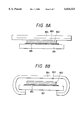
- FIGS. 8A and 8B are schematic, structural views for showing a method for producing the solar cell module of the present invention.
- FIG. 9A is a plan view for showing the solar cell device of Example 1, and
- FIG. 9B is a cross-sectional view taken along the line 9B--9B of FIG. 9A.
- FIGS. 10A and 10B are perspective views for showing examples of the shape of a constructional member integrated with the solar cell according to the present invention.
- FIG. 1 is a schematic, structural view for showing a solar cell module according to the present invention.
- a solar cell device 102 is sealed with a sealing material 103 of a resin through an insulating member 105 on a support member 101 and the surface is covered with a protective film 104.
- the protective film 104 and the sealing material 103 are turned to the back of the support member 101 so as to cover the edge of the support member. Otherwise, either the protective film 104 or the sealing material 103 covers the edge of the support member.
- the structure for covering the edge in the covering step has the following effect.
- the protective film be stable against heat, light, and water (i.e., excellent in weather resistance).
- the protective film is desirably resistant to contamination so as to prevent decrease in efficiency of solar cell device due to contamination.
- the protective film is desired to have water repellency.
- the water repellency is desired such that a contact angle of water is preferably not less than 50° and more preferably not less than 70°.
- the protective film is made of fluororesin or silicone resin.
- the protective film is preferably one that can be turned back.
- the protective film is made of the fluororesin.
- the fluororesin are tetrafluoroethylene-hexafluoropropylene copolymer, tetrafluoroethylene-perfluoroalkylvinyl ether copolymer, polychlorotrifluoroethylene, polyvinylidene fluoride, polyvinyl fluoride, ethylene-tetrafluoroethylene copolymer, and ethylene-chlorotrifluoroethylene copolymer.
- the protective film is preferably processed by a plasma treatment, a corona discharge treatment, an ozone treatment, or coating of primer in order to assure the adhesion strength to the sealing material.
- the sealing material needs to protect the solar cell device from stress or the like from the outside and function to sufficiently transmit rays necessary for photoelectric conversion of the solar cell device.
- the resin for the sealing material needs to be excellent in transparency, weather resistance, and adhesion. For filling uneven portions on the surface of the solar cell device, it needs to have flowability in the production step of the solar cell module.
- the material is selected from thermoplastic resins. Specific materials thereof are ethylene-vinyl acetate copolymer (EVA), polyvinyl butyral, silicone resin, acrylic resin, and so on.
- the adhesion strength of the sealing material can be increased by also using a silane coupling agent or a titanate coupling agent.
- An ultraviolet absorbing agent is desirably blended in the aforementioned adhesive resin forming the sealing material so as to provide the sealing material with a desired ultraviolet intercepting function.
- the ultraviolet absorbing agent used in this case may be either an organic ultraviolet absorbing agent or an inorganic ultraviolet absorbing agent.
- the sealing material is preferably reinforced in order to increase the mechanical strength. Specific materials are preferably a sealing material in which nonwoven fabric of glass fibers or nonwoven fabric of organic fibers is sealed upon the covering step, and a sealing material in which fillers such as glass staples or glass beads are preliminarily mixed in the resin for the sealing material.
- the support member used in the present invention is selected from steel sheets, glass fiber reinforced plastics, hard plastics, lumber, and so on.
- a preferred structure is such that the edge is bent by folding so as to enhance rigidity and to fit the edge in a channel as a mounting member.
- Materials suitable for this processing are a steel sheet and a stainless steel sheet. These materials are resistant to melting or deformation under high-temperature flame and are also preferably used as roof members.
- the materials for the support member should be preferably excellent in rust proofing and weather resistance. For attaining the above characteristics, application of a paint with excellent weather resistance is adopted in general.
- the protective film 804 and sealing material 803 larger in size than the support member 801 are stacked on a solar cell device 802.
- An insulating member 805 is provided between the solar cell device 802 and the support member 801.
- the protruded portions of the protective film and sealing material outside the support member 801 are turned to the back of the support member.
- the sealing material is softened by hot pressing to seal the solar cell device 802, thereby achieving the structure for covering the edge of the support member with the protective film and the sealing material, as shown in FIG. 8B.
- FIG. 2 shows an example of the solar cell device.
- Reference numeral 201 designates an electroconductive substrate, 202 a back reflecting layer, 203 a semiconductor photoactive layer, 204 a transparent, electroconductive layer, 205 a collector electrode, 206 an output terminal, 207 solder, and 209 an insulating member.
- the electroconductive substrate 201 functions as a substrate of the solar cell device and also functions as a lower electrode.
- the electroconductive substrate 201 may be made of a material selected from the group of silicon, tantalum, molybdenum, tungsten, stainless steel, aluminum, copper, titanium, a carbon sheet, a lead-plated iron sheet, and a resin film and ceramic material having an electroconductive layer formed thereon.
- a metal layer, or a metallic oxide layer, or a combination of the metal layer and metallic oxide layer may be formed as the back reflecting layer 202 on the above-stated electroconductive substrate 201.
- the metal layer is, for example, of Ti, Cr, Mo, W, Al, Ag, Ni or the like
- the metallic oxide layer is, for example, of ZnO, TiO 2 , SnO 2 or the like.
- the metal layer and the metallic oxide layer can be made by a method selected from the resistance heating vapor deposition method, the electron beam vapor deposition method, the sputtering method, and so on.
- the semiconductor photoactive layer 203 is a section for undergoing photoelectric conversion.
- Specific examples of materials for the semiconductor photoactive layer 203 include pn junction type polycrystalline silicon, pin junction type amorphous silicon, and compound semiconductors such as CuInSe 2 , CuInS 2 , GaAs, CdS/Cu 2 S, CdS/CdTe, CdS/InP, and CdTe/Cu 2 Te.
- the semiconductor photoactive layer may be made by sheeting of molten silicon or by a heat treatment of amorphous silicon in the case of polycrystalline silicon; or by a plasma enhanced CVD using silane gas and the like as a raw material in the case of amorphous silicon; or by ion plating, ion beam deposition, vacuum vapor deposition, sputtering, or electrodeposition in the case of the compound semiconductors.
- the transparent, electroconductive layer 204 serves as an upper electrode of the solar cell device.
- the transparent, electroconductive layer 204 may be made of a material selected, for example, from In 2 O 3 , SnO 2 , In 2 O 3 --SnO 2 (ITO), ZnO, TiO 2 , Cd 2 SnO 4 , and crystalline semiconductors doped with a high concentration of impurities.
- a method for forming the transparent, electroconductive layer 204 may be selected from the resistance heating vapor deposition, sputtering, spraying, CVD, and impurity diffusion methods.
- the collector electrode 205 (grid) of a grating pattern may be provided on the transparent, electroconductive layer, for efficiently collecting electric currents.
- Specific materials for the collector electrode 205 are, for example, electroconductive pastes formed by dispersing fine powder of silver, gold, copper, nickel, carbon or the like in a binder polymer.
- the binder polymer is selected from polyester, epoxy, acrylic, alkyd, polyvinyl acetate, rubber, urethane, and phenol resins.
- a method for forming the collector electrode 205 may be selected from sputtering, resistance heating and CVD methods using a mask pattern; a method for evaporating a metal film over the entire surface and then removing unnecessary portions by etching to form patterning; a method for directly forming the grid electrode pattern by photo-CVD; and a method for forming a mask of a negative pattern of the grid electrode pattern and then performing plating thereon.
- the output terminals 206 are attached to the conductive substrate and to the collector electrode, for taking out the electromotive force.
- the output terminal is attached to the electroconductive substrate by a method for bonding a metal member such as a copper tab thereto by spot welding or soldering.
- the output terminal is attached to the collector electrode by a method for electrically connecting a metal member thereto by an electroconductive adhesive or solder 207.
- the insulating member 209 is desirably provided in order to prevent the output terminal from touching the electroconductive substrate and semiconductor layer to cause short-circuit.
- Solar cell devices produced by the above techniques are connected in series or in parallel, depending upon desired voltage or electric current.
- Another arrangement may be such that solar cell devices are integrated on an insulated substrate to achieve the desired voltage or current.
- the insulating member 105 has a function to make insulation surer between the solar cell device and the support member.
- the other characteristics demanded for the insulating member include electric insulation, mechanical strength, insulation under wet conditions, and heat resistance.
- an adhesive can be used at the interface to the insulating member.
- the work efficiency can be increased more by the structure in which the adhesive, the insulating member, and the adhesive are preliminarily stacked in an integral form.
- the adhesive used in the present invention is desired to have such thermal characteristics of melting at a high temperature and further undergoing crosslinking at a high temperature. However, in applications wherein temperatures of the module are increased to only 80° C. or so, the crosslinking at a high temperature is not so important.
- the insulating member is preferably made of a material similar to the sealing material.
- the insulating member is normally made of a material selected from biaxially oriented polyethylene terephthalate (PET), nylon, and nonwoven fabric of glass fibers or plastic fibers.
- FIGS. 10A and 10B show examples of the shape of a roof member.
- FIG. 10A shows an example of the batten seam roofing type and FIG. 10B an example of the horizontal roofing type. They are used with an inverter, thus constituting a sunlight-utilizing electric power generation apparatus.
- a protective film 301, a sealing material 302, a glass-fiber nonwoven fabric 303, a solar cell device 304, an insulating member 305, and a support member 306 were prepared as mentioned below and these were stacked on the support member to produce a solar cell module.
- the support member 306 prepared was a galvanized steel sheet (Hardwearing color GL 0.4 mm thick, produced by Daido Kohan).
- the sealing material 302 was prepared by mixing 100 parts by weight of ethylene-vinyl acetate (vinyl acetate 33% by weight, melt flow rate 30), 1.5 parts by weight of 2,5-dimethyl-2,5-bis(t-butylperoxy)hexane as a crosslinking agent, 0.3 part by weight of 2-hydroxy-4-n-octoxybenzophenone as an UV absorber, 0.2 part by weight of tris(mono-nonylphenyl)phosphate as an antioxidant, and 0.1 part by weight of (2,2 6,6-tetramethyl-4-piperidyl) sebacate as a light stabilizer, and forming a sheet 460 ⁇ m thick by use of T die and extruder. This sheet of the sealing material softens when heated.
- the insulating member 305 was prepared by laying a layer of the same resin as the sealing material in the thickness of 200 ⁇ m on each of the both surfaces of biaxially oriented polyethylene terephthalate film (Tetron S 50 ⁇ m thick, available from Teijin LTD.) the both surfaces of which were corona-treated.
- biaxially oriented polyethylene terephthalate film Tetron S 50 ⁇ m thick, available from Teijin LTD.
- the solar cell device 304 having the structure shown in FIGS. 9A and 9B was produced in the following manner. First, a beltlike stainless-steel substrate 901 cleaned was prepared, and on the substrate an Al layer (5000 ⁇ thick) and a ZnO layer (5000 ⁇ thick) were successively formed as a back reflecting layer 902 by sputtering.
- an n-type amorphous silicon layer was formed by using a gas mixture of SiH 4 , PH 3 , and H 2
- an i-type amorphous silicon layer was formed by using a gas mixture of SiH 4 and H 2
- a p-type microcrystalline silicon ( ⁇ c-Si) layer was formed by using a gas mixture of SiH 4 , BF 3 , and H 2 to form a tandem type amorphous silicon photoelectric conversion semiconductor layer 903 in the layer structure of n-type layer 150 ⁇ thick/i-type layer 4000 thick/p-type layer 100 thick/n-type layer 100 ⁇ thick/i-type layer 800 ⁇ thick/p-type layer 100 ⁇ thick.
- the transparent, electroconductive layer 904 was obtained by evaporating In under O 2 atmosphere by the resistance heating method to form an In 2 O 3 thin film (700 ⁇ thick).
- the obtained body was cut and then etched by screen printing, thus obtaining a plurality of the devices in the size of 30 cm ⁇ 9 cm.
- grid electrodes 905 for collection of electricity were formed by screen printing with a silver paste (trade number: #5007, produced by DuPont Inc.).
- collector electrodes were connected by bonding a wire busbar 906 (solder-plated copper wire having the diameter of 400 ⁇ m) thereto with a silver paste 907 (trade number: #220, produced by Amicon).
- a copper tab 908 (100 ⁇ m thick) was attached to the stainless steel substrate by spot welding, thus obtaining the solar cell device.
- the solar cell device 304 was prepared as described above.
- the protective film 301 prepared was a non-oriented ethylene-tetrafluoroethylene film (TEFZEL 50 ⁇ m thick, produced by DuPont Inc.).
- the surface of the film to be bonded to the sealing material 302 was preliminarily processed by the plasma treatment.
- the glass nonwoven fabric 303 prepared was a nonwoven fabric of glass fibers (Glassper GMC-00-040, wire diameter 10 ⁇ m, basic weight 40 g/m 2 , produced by Honshu Seishi).
- Hot pressing was performed by using a vacuum lamination apparatus shown in FIG. 5 and the following manner.
- a PFA film Teflon PFA 50 ⁇ m thick, produced by DuPont Inc.
- a PFA film for prevention of contamination was laid on an aluminum plate 510 (10 mm thick). Stacked thereon were the support member 506, the insulating member 505, the solar cell device 504, the glass nonwoven fabric 503, the sheet of the sealing material 502, and the protective film 501.
- the sealing material and the protective film were preliminarily scored and their edges were put into between the support member and the PFA film.
- a sheet 511 (3 mm thick) of heat-resistant silicone rubber was placed on the lamination.
- the pressure inside the lamination was reduced down to 10 mmHg by a vacuum pump, using O ring 512 as a sealing member.
- the lamination was put in a hot-air drying furnace at 150° C. while continuously evacuating.
- the lamination was taken out 100 minutes after. This softened the sheet of the sealing material to seal the solar cell device 504 with the sheet.
- the lamination was cooled down to room temperature while evacuating.
- a plurality of solar cell device modules as shown in FIGS. 3A and 3B were obtained in this way.
- the solar cell modules thus obtained were evaluated by the following methods.
- the solar cell modules were subjected to 200 cycles of temperature/humidity cycle test of -40° C./one hour and 85° C./85% RH/four hours and thereafter the solar cell modules were evaluated as to their appearance by visual observation.
- the evaluation result is shown in Table 1, based on the following evaluation criteria.
- the evaluation criteria were as follows:
- the solar cell modules were exposed to high temperature and high humidity of 85° C./85% RH/5000 hours.
- the solar cell modules were then evaluated as to the change in appearance.
- the evaluation result is shown in Table 1, based on the following evaluation criteria.
- One test cycle involves salt spray for two hours, drying for four hours, and wetting for two hours.
- the salt spray was carried out at the temperature of 35° C. and the concentration of salt water was 5 ⁇ 0.5% .
- the drying was done at 60 ⁇ 1° C. and the relative humidity of 20 to 30%.
- the wetting was done at the temperature of 50 ⁇ 1° C. and the relative humidity of 95% or more.
- the solar cell modules were evaluated as to the change in appearance. The evaluation result is shown in Table 1, based on the following evaluation criteria. The evaluation criteria were as follows:
- the time necessitated for the process to prevent peeling at the edge was measured.
- the evaluation result was expressed by minutes of the time necessitated for production of one module.
- the solar cell modules were produced in the same manner as in Example 1 except that an acrylic resin film (PMMA 50 ⁇ m) was used in place of the ethylene-tetrafluoroethylene copolymer film (ETFE 50 ⁇ m) used in Example 1.
- the evaluation results are shown in Table 1.
- the solar cell modules were produced in the same manner as in Example 2 except that a fiber reinforced plastic (FRP) film (2 mm) was used as the support member in place of the galvanized steel sheet used in Example 2.
- the evaluation results except for the salt spray test are shown in Table 1. Since the FRP film used as the support member does not rust, the salt spray test was not conducted.
- a glass 401, a sheet of a sealing material 402, a solar cell device 403, a sheet of a sealing material 404, and a back film 405 were prepared as mentioned below and they were stacked on the support plate. Then they were hot-pressed to produce the solar cell module. Since the glass 401 used as the support member does not rust, the salt spray test was not conducted.
- the glass 401 prepared was white sheet glass (3.3 mm).
- the sheet of the sealing material was the same as that of Example 1.
- the solar cell device was the same as that in Example 1.
- the back film prepared was an aluminum sheet (120 ⁇ m) the both surfaces of which were coated with PVF.
- a PFA film (Teflon PFA 50 ⁇ m thick, produced by DuPont Inc.) for prevention of contamination was laid on the aluminum plate 501 (10 mm thick), and the glass 401, the sheet of the sealing material 402, the solar cell device 403, the sheet of the sealing material 404, and the back film 405 prepared as described above were stacked thereon.
- the sealing material and the back film were preliminarily scored and the edges thereof were put into between the support member and the PFA film.
- the sheet 502 of heat-resistant silicone rubber (3 mm thick) was laid on the lamination. Then the pressure inside the lamination was reduced down to 10 mmHg by the vacuum pump, using the O ring 503 as a sealing member.
- the solar cell modules were produced in the same way as in Example 1 except that the protective film and the sealing material had the same size as the support member and thus they were not turned to the back of the support member.
- the evaluation results are shown in Table 1.
- the solar cell modules were produced in the same manner as in Comparative Example 1 except that the peeling preventing member was attached to the edge of the solar cell module as follows.
- the peeling preventing member was attached to the edge of the solar cell module in the following procedures.
- a silicone sealant was applied to the peeling preventing member of an U-shaped and painted steel plate.
- the peeling preventing member was engaged with the solar cell module and then it was confirmed that unnecessary amount of the silicone sealant was protruded on the surface of all the engaged portions.
Abstract
Description
              TABLE 1
______________________________________
       Durability                  Time for
  against   produc-
  temperature High  tion of
  and temperature/ Salt one
  humidity high humidity spray module
  change test test (min)
______________________________________
Example 1
         ⊚
                    ⊚
                               ⊚
                                     5
  Example 2 ⊚ ⊚ ⊚ 5
  Example 3 ⊚ ⊚ -- 5
  Example 4 ⊚ ⊚ -- 5
  Comp. Ex 1 ∘ ∘ x 5
  Comp. Ex 2 ∘ ∘ ∘ 15
______________________________________
Claims (14)
Applications Claiming Priority (2)
| Application Number | Priority Date | Filing Date | Title |
|---|---|---|---|
| JP9035121A JPH10233521A (en) | 1997-02-19 | 1997-02-19 | Solar battery module, building material integrated with solar battery using it, and photovoltaic power generator |
| JP9-035121 | 1997-02-19 |
Publications (1)
| Publication Number | Publication Date |
|---|---|
| US6034323A true US6034323A (en) | 2000-03-07 |
Family
ID=12433110
Family Applications (1)
| Application Number | Title | Priority Date | Filing Date |
|---|---|---|---|
| US09/024,863 Expired - Lifetime US6034323A (en) | 1997-02-19 | 1998-02-17 | Solar cell module |
Country Status (6)
| Country | Link |
|---|---|
| US (1) | US6034323A (en) |
| EP (1) | EP0860886A3 (en) |
| JP (1) | JPH10233521A (en) |
| KR (1) | KR19980071511A (en) |
| CN (1) | CN1195201A (en) |
| AU (1) | AU747454B2 (en) |
Cited By (37)
| Publication number | Priority date | Publication date | Assignee | Title |
|---|---|---|---|---|
| US6414236B1 (en) | 1999-06-30 | 2002-07-02 | Canon Kabushiki Kaisha | Solar cell module |
| US6552258B2 (en) * | 2000-09-11 | 2003-04-22 | Sanyo Electric Co., Ltd. | Solar cell module |
| US20040171187A1 (en) * | 2002-12-13 | 2004-09-02 | Canon Kabushiki Kaisha | Method of producing solar cell module |
| US20040191949A1 (en) * | 2003-03-25 | 2004-09-30 | Canon Kabushiki Kaisha | Zinc oxide film treatment method and method of manufacturing photovoltaic device utilizing the same |
| US20040191422A1 (en) * | 2003-03-24 | 2004-09-30 | Canon Kabushiki Kaisha | Method for manufacturing solar cell module having a sealing resin layer formed on a metal oxide layer |
| US20040244829A1 (en) * | 2003-06-04 | 2004-12-09 | Rearick Brian K. | Coatings for encapsulation of photovoltaic cells |
| US20040255999A1 (en) * | 2003-04-17 | 2004-12-23 | Canon Kabushiki Kaisha | Solar cell module with power converters |
| US20040261836A1 (en) * | 2003-04-17 | 2004-12-30 | Canon Kabushiki Kaisha | Solar cell module and solar cell module array |
| US20050000562A1 (en) * | 2003-04-10 | 2005-01-06 | Canon Kabushiki Kaisha | Solar cell module having an electric device |
| US20050103376A1 (en) * | 2003-11-14 | 2005-05-19 | Canon Kabushiki Kaisha | Solar cell module and manufacturing method therefor |
| US20050126622A1 (en) * | 2003-12-11 | 2005-06-16 | Canon Kabushiki Kaisha | Solar cell module and method of producing the same |
| US20050133086A1 (en) * | 2003-12-19 | 2005-06-23 | Canon Kabushiki Kaisha | Solar cell module with conductor member and with bypass diode arranged on condcutor member, and method of producing same |
| US20050133083A1 (en) * | 2003-12-19 | 2005-06-23 | Canon Kabushiki Kaisha | Solar cell module |
| US20050178428A1 (en) * | 2004-02-17 | 2005-08-18 | Solar Roofing Systems Inc. | Photovoltaic system and method of making same |
| US20060225777A1 (en) * | 2005-04-11 | 2006-10-12 | Unaxis Balzers Ltd. | Solar cell module and method of encapsulating same |
| US20080104732A1 (en) * | 1998-04-08 | 2008-05-01 | Commonwealth Scientific And Industrial Research Organization | Methods and means for obtaining modified phenotypes |
| US20100071756A1 (en) * | 2009-05-12 | 2010-03-25 | Miasole | Isolated metallic flexible back sheet for solar module encapsulation |
| US20100071757A1 (en) * | 2009-05-12 | 2010-03-25 | Miasole | Isolated metallic flexible back sheet for solar module encapsulation |
| US20100101561A1 (en) * | 2008-10-24 | 2010-04-29 | Christopher Frank | Solar panels systems and methods |
| US20100294341A1 (en) * | 2008-10-24 | 2010-11-25 | Christopher Frank | Apparatus and methods for frameless building integrated photovoltaic panel |
| US20110036389A1 (en) * | 2009-08-11 | 2011-02-17 | Miasole | Cte modulated encapsulants for solar modules |
| US20110036390A1 (en) * | 2009-08-11 | 2011-02-17 | Miasole | Composite encapsulants containing fillers for photovoltaic modules |
| US20110108094A1 (en) * | 2008-06-26 | 2011-05-12 | Du Pont-Mitsui Polychemicals Co., Ltd. | Laminated sheet for solar cell and solar cell module using the same |
| US20110139224A1 (en) * | 2009-12-16 | 2011-06-16 | Miasole | Oriented reinforcement for frameless solar modules |
| US20110214716A1 (en) * | 2009-05-12 | 2011-09-08 | Miasole | Isolated metallic flexible back sheet for solar module encapsulation |
| CN101504956B (en) * | 2003-11-27 | 2012-01-11 | 京瓷株式会社 | Solar cell module |
| US8664030B2 (en) | 1999-03-30 | 2014-03-04 | Daniel Luch | Collector grid and interconnect structures for photovoltaic arrays and modules |
| US8729385B2 (en) | 2006-04-13 | 2014-05-20 | Daniel Luch | Collector grid and interconnect structures for photovoltaic arrays and modules |
| US8822810B2 (en) | 2006-04-13 | 2014-09-02 | Daniel Luch | Collector grid and interconnect structures for photovoltaic arrays and modules |
| US8884155B2 (en) | 2006-04-13 | 2014-11-11 | Daniel Luch | Collector grid and interconnect structures for photovoltaic arrays and modules |
| US9006563B2 (en) | 2006-04-13 | 2015-04-14 | Solannex, Inc. | Collector grid and interconnect structures for photovoltaic arrays and modules |
| US20160005905A1 (en) * | 2014-07-07 | 2016-01-07 | Lg Electronics Inc. | Solar cell module |
| US9236512B2 (en) | 2006-04-13 | 2016-01-12 | Daniel Luch | Collector grid and interconnect structures for photovoltaic arrays and modules |
| US9865758B2 (en) | 2006-04-13 | 2018-01-09 | Daniel Luch | Collector grid and interconnect structures for photovoltaic arrays and modules |
| US20180151767A1 (en) * | 2016-11-29 | 2018-05-31 | Christopher Dwight Barnes | Solar panel system |
| US10399892B2 (en) | 2012-04-17 | 2019-09-03 | Arkema Inc. | Aqueous fluoropolymer glass coating |
| US10490682B2 (en) | 2018-03-14 | 2019-11-26 | National Mechanical Group Corp. | Frame-less encapsulated photo-voltaic solar panel supporting solar cell modules encapsulated within multiple layers of optically-transparent epoxy-resin materials |
Families Citing this family (15)
| Publication number | Priority date | Publication date | Assignee | Title |
|---|---|---|---|---|
| EP1099532B1 (en) * | 1999-10-28 | 2004-06-16 | Bridgestone Corporation | Method of surface treating and laminating a fluorine resin |
| JP2001291881A (en) | 2000-01-31 | 2001-10-19 | Sanyo Electric Co Ltd | Solar battery module |
| EP1172864A1 (en) * | 2000-07-11 | 2002-01-16 | SANYO ELECTRIC Co., Ltd. | Solar cell module |
| JP3889644B2 (en) | 2002-03-25 | 2007-03-07 | 三洋電機株式会社 | Solar cell module |
| JP4534243B2 (en) * | 2003-08-20 | 2010-09-01 | 富士電機システムズ株式会社 | Manufacturing method of solar cell module |
| JP4720174B2 (en) * | 2004-12-15 | 2011-07-13 | 富士電機システムズ株式会社 | Solar cell module |
| DE102008045997A1 (en) * | 2007-10-23 | 2009-04-30 | Bluenergy Ag | Encapsulated solar cell |
| JP2010123616A (en) * | 2008-11-17 | 2010-06-03 | Mitsubishi Electric Corp | Solar cell panel |
| KR101142826B1 (en) * | 2009-10-27 | 2012-05-08 | 한국철강 주식회사 | Photovoltaic Device and Method for manufacturing the same |
| EP2320479A1 (en) * | 2009-11-04 | 2011-05-11 | Sika Technology AG | Edge sealing of photovoltaic modules |
| JP2012094608A (en) * | 2010-10-26 | 2012-05-17 | Fujifilm Corp | Solar cell module |
| JP5875805B2 (en) * | 2011-09-05 | 2016-03-02 | 日清紡メカトロニクス株式会社 | Solar cell module |
| JP6308901B2 (en) * | 2014-07-15 | 2018-04-11 | 三菱電機株式会社 | Solar cell module and solar cell module manufacturing apparatus |
| CN104201977A (en) * | 2014-09-16 | 2014-12-10 | 常熟建工建设集团有限公司苏州分公司 | Solar wallboard |
| TWM527612U (en) * | 2016-04-14 | 2016-08-21 | 豪客能源科技股份有限公司 | Solar power module |
Citations (5)
| Publication number | Priority date | Publication date | Assignee | Title |
|---|---|---|---|---|
| JPS61133674A (en) * | 1984-12-03 | 1986-06-20 | Mitsubishi Electric Corp | Solar battery module |
| JPH04349672A (en) * | 1991-05-27 | 1992-12-04 | Canon Inc | Solar cell module |
| EP0625802A2 (en) * | 1993-05-18 | 1994-11-23 | Canon Kabushiki Kaisha | Solar cell module and installation method thereof |
| EP0747971A2 (en) * | 1995-06-07 | 1996-12-11 | United Solar Systems Corporation | Photovoltaic shingle system |
| WO1997050131A2 (en) * | 1996-06-27 | 1997-12-31 | Evergreen Solar, Inc. | Solar modules with integral mounting structure and methods for forming same |
-
1997
- 1997-02-19 JP JP9035121A patent/JPH10233521A/en active Pending
-
1998
- 1998-02-17 US US09/024,863 patent/US6034323A/en not_active Expired - Lifetime
- 1998-02-18 EP EP98102817A patent/EP0860886A3/en not_active Ceased
- 1998-02-18 AU AU55368/98A patent/AU747454B2/en not_active Ceased
- 1998-02-19 KR KR1019980005170A patent/KR19980071511A/en not_active Application Discontinuation
- 1998-02-19 CN CN98107701A patent/CN1195201A/en active Pending
Patent Citations (5)
| Publication number | Priority date | Publication date | Assignee | Title |
|---|---|---|---|---|
| JPS61133674A (en) * | 1984-12-03 | 1986-06-20 | Mitsubishi Electric Corp | Solar battery module |
| JPH04349672A (en) * | 1991-05-27 | 1992-12-04 | Canon Inc | Solar cell module |
| EP0625802A2 (en) * | 1993-05-18 | 1994-11-23 | Canon Kabushiki Kaisha | Solar cell module and installation method thereof |
| EP0747971A2 (en) * | 1995-06-07 | 1996-12-11 | United Solar Systems Corporation | Photovoltaic shingle system |
| WO1997050131A2 (en) * | 1996-06-27 | 1997-12-31 | Evergreen Solar, Inc. | Solar modules with integral mounting structure and methods for forming same |
Non-Patent Citations (4)
| Title |
|---|
| M. Izu et al., "Lightweight Flexible Rooftop PV Module", IEEE World Conf. on Photovoltaic Energy, Dec. 5, 1994, pp. 990-993. |
| M. Izu et al., Lightweight Flexible Rooftop PV Module , IEEE World Conf. on Photovoltaic Energy, Dec. 5, 1994, pp. 990 993. * |
| Patent Abstracts of Japan, vol. 017, No. 213 (E 1356), Apr. 26, 1993 (corresponding to JP 4 349672). * |
| Patent Abstracts of Japan, vol. 017, No. 213 (E-1356), Apr. 26, 1993 (corresponding to JP 4-349672). |
Cited By (49)
| Publication number | Priority date | Publication date | Assignee | Title |
|---|---|---|---|---|
| US20080104732A1 (en) * | 1998-04-08 | 2008-05-01 | Commonwealth Scientific And Industrial Research Organization | Methods and means for obtaining modified phenotypes |
| US8664030B2 (en) | 1999-03-30 | 2014-03-04 | Daniel Luch | Collector grid and interconnect structures for photovoltaic arrays and modules |
| US6414236B1 (en) | 1999-06-30 | 2002-07-02 | Canon Kabushiki Kaisha | Solar cell module |
| US6552258B2 (en) * | 2000-09-11 | 2003-04-22 | Sanyo Electric Co., Ltd. | Solar cell module |
| US20040171187A1 (en) * | 2002-12-13 | 2004-09-02 | Canon Kabushiki Kaisha | Method of producing solar cell module |
| US7749351B2 (en) | 2002-12-13 | 2010-07-06 | Canon Kabushiki Kaisha | Method of producing solar cell module |
| US20040191422A1 (en) * | 2003-03-24 | 2004-09-30 | Canon Kabushiki Kaisha | Method for manufacturing solar cell module having a sealing resin layer formed on a metal oxide layer |
| US7303788B2 (en) | 2003-03-24 | 2007-12-04 | Canon Kabushiki Kaisha | Method for manufacturing solar cell module having a sealing resin layer formed on a metal oxide layer |
| US7282132B2 (en) | 2003-03-25 | 2007-10-16 | Canon Kabushiki Kaisha | Zinc oxide film treatment method and method of manufacturing photovoltaic device utilizing the same |
| US20040191949A1 (en) * | 2003-03-25 | 2004-09-30 | Canon Kabushiki Kaisha | Zinc oxide film treatment method and method of manufacturing photovoltaic device utilizing the same |
| US20050000562A1 (en) * | 2003-04-10 | 2005-01-06 | Canon Kabushiki Kaisha | Solar cell module having an electric device |
| US7534956B2 (en) | 2003-04-10 | 2009-05-19 | Canon Kabushiki Kaisha | Solar cell module having an electric device |
| US20040255999A1 (en) * | 2003-04-17 | 2004-12-23 | Canon Kabushiki Kaisha | Solar cell module with power converters |
| US20040261836A1 (en) * | 2003-04-17 | 2004-12-30 | Canon Kabushiki Kaisha | Solar cell module and solar cell module array |
| US20040244829A1 (en) * | 2003-06-04 | 2004-12-09 | Rearick Brian K. | Coatings for encapsulation of photovoltaic cells |
| US20050103376A1 (en) * | 2003-11-14 | 2005-05-19 | Canon Kabushiki Kaisha | Solar cell module and manufacturing method therefor |
| CN101504956B (en) * | 2003-11-27 | 2012-01-11 | 京瓷株式会社 | Solar cell module |
| US20050126622A1 (en) * | 2003-12-11 | 2005-06-16 | Canon Kabushiki Kaisha | Solar cell module and method of producing the same |
| US7238879B2 (en) | 2003-12-19 | 2007-07-03 | Canon Kabushiki Kaisha | Solar cell module |
| US20050133083A1 (en) * | 2003-12-19 | 2005-06-23 | Canon Kabushiki Kaisha | Solar cell module |
| US20050133086A1 (en) * | 2003-12-19 | 2005-06-23 | Canon Kabushiki Kaisha | Solar cell module with conductor member and with bypass diode arranged on condcutor member, and method of producing same |
| US20050178428A1 (en) * | 2004-02-17 | 2005-08-18 | Solar Roofing Systems Inc. | Photovoltaic system and method of making same |
| US20060225777A1 (en) * | 2005-04-11 | 2006-10-12 | Unaxis Balzers Ltd. | Solar cell module and method of encapsulating same |
| US7868246B2 (en) * | 2005-04-11 | 2011-01-11 | Oerlikon Solar Ag | Solar cell module and method of encapsulating same |
| US8822810B2 (en) | 2006-04-13 | 2014-09-02 | Daniel Luch | Collector grid and interconnect structures for photovoltaic arrays and modules |
| US8729385B2 (en) | 2006-04-13 | 2014-05-20 | Daniel Luch | Collector grid and interconnect structures for photovoltaic arrays and modules |
| US9236512B2 (en) | 2006-04-13 | 2016-01-12 | Daniel Luch | Collector grid and interconnect structures for photovoltaic arrays and modules |
| US9006563B2 (en) | 2006-04-13 | 2015-04-14 | Solannex, Inc. | Collector grid and interconnect structures for photovoltaic arrays and modules |
| US8884155B2 (en) | 2006-04-13 | 2014-11-11 | Daniel Luch | Collector grid and interconnect structures for photovoltaic arrays and modules |
| US9865758B2 (en) | 2006-04-13 | 2018-01-09 | Daniel Luch | Collector grid and interconnect structures for photovoltaic arrays and modules |
| US20110108094A1 (en) * | 2008-06-26 | 2011-05-12 | Du Pont-Mitsui Polychemicals Co., Ltd. | Laminated sheet for solar cell and solar cell module using the same |
| DE112009001575B4 (en) | 2008-06-26 | 2022-10-06 | Dow-Mitsui Polychemicals Co.,Ltd. | Process for producing a laminated film for a solar cell |
| US20100294341A1 (en) * | 2008-10-24 | 2010-11-25 | Christopher Frank | Apparatus and methods for frameless building integrated photovoltaic panel |
| US20100101561A1 (en) * | 2008-10-24 | 2010-04-29 | Christopher Frank | Solar panels systems and methods |
| US20110214716A1 (en) * | 2009-05-12 | 2011-09-08 | Miasole | Isolated metallic flexible back sheet for solar module encapsulation |
| US20100071757A1 (en) * | 2009-05-12 | 2010-03-25 | Miasole | Isolated metallic flexible back sheet for solar module encapsulation |
| US7960643B2 (en) | 2009-05-12 | 2011-06-14 | Miasole | Isolated metallic flexible back sheet for solar module encapsulation |
| US20100071756A1 (en) * | 2009-05-12 | 2010-03-25 | Miasole | Isolated metallic flexible back sheet for solar module encapsulation |
| US7829783B2 (en) | 2009-05-12 | 2010-11-09 | Miasole | Isolated metallic flexible back sheet for solar module encapsulation |
| US20110036390A1 (en) * | 2009-08-11 | 2011-02-17 | Miasole | Composite encapsulants containing fillers for photovoltaic modules |
| US20110036389A1 (en) * | 2009-08-11 | 2011-02-17 | Miasole | Cte modulated encapsulants for solar modules |
| US20110139224A1 (en) * | 2009-12-16 | 2011-06-16 | Miasole | Oriented reinforcement for frameless solar modules |
| US10399892B2 (en) | 2012-04-17 | 2019-09-03 | Arkema Inc. | Aqueous fluoropolymer glass coating |
| US20160005905A1 (en) * | 2014-07-07 | 2016-01-07 | Lg Electronics Inc. | Solar cell module |
| US20180151767A1 (en) * | 2016-11-29 | 2018-05-31 | Christopher Dwight Barnes | Solar panel system |
| US10490682B2 (en) | 2018-03-14 | 2019-11-26 | National Mechanical Group Corp. | Frame-less encapsulated photo-voltaic solar panel supporting solar cell modules encapsulated within multiple layers of optically-transparent epoxy-resin materials |
| US10522700B2 (en) | 2018-03-14 | 2019-12-31 | National Mechanical Group Corp. | Frame-less encapsulated photo-voltaic (PV) solar power panel supporting solar cell modules encapsulated within optically-transparent epoxy-resin material coating a phenolic resin support sheet |
| US10522701B2 (en) | 2018-03-14 | 2019-12-31 | National Mechanical Group Corp. | Solar power panel factory and process for manufacturing frame-less encapsulated photo-voltaic (PV) solar power panels by encapsulating solar cell modules within optically-transparent epoxy-resin material coating phenolic resin support sheets |
| US10529880B2 (en) | 2018-03-14 | 2020-01-07 | National Mechanical Group Corp. | Solar power panel factory and process for manufacturing frame-less encapsulated photo-voltaic (PV) solar power panels by encapsulating solar cell modules on a phenolic sheet beneath a polycarbonate panel using optically transparent epoxy-resin material |
Also Published As
| Publication number | Publication date |
|---|---|
| CN1195201A (en) | 1998-10-07 |
| AU5536898A (en) | 1998-08-27 |
| AU747454B2 (en) | 2002-05-16 |
| EP0860886A2 (en) | 1998-08-26 |
| EP0860886A3 (en) | 1999-01-07 |
| JPH10233521A (en) | 1998-09-02 |
| KR19980071511A (en) | 1998-10-26 |
Similar Documents
| Publication | Publication Date | Title |
|---|---|---|
| US6034323A (en) | Solar cell module | |
| KR100325955B1 (en) | Solar Cell Module and Reinforcing Member for Solar Cell Module | |
| CA2161077C (en) | Solar cell module and manufacturing method thereof | |
| JP3618802B2 (en) | Solar cell module | |
| US5389159A (en) | Solar cell module and method for producing the same | |
| US5973258A (en) | Photovoltaic device | |
| AU741432B2 (en) | Solar cell module and method for manufacturing same | |
| US6541693B2 (en) | Solar cell module and process for its production, and solar cell module installing method and solar electricity generation system | |
| US6311436B1 (en) | Solar roof member | |
| US20010054437A1 (en) | Solar cell module | |
| JP2000216415A (en) | Solar cell module, its manufacture and working method, and solar battery power generation system using the solar cell module | |
| JPH06140651A (en) | Solar cell module | |
| JP2002111036A (en) | Solar battery module and its execution method | |
| JP3548379B2 (en) | Photovoltaic device and manufacturing method thereof | |
| JP3754806B2 (en) | Solar cell module and manufacturing method thereof | |
| JP3679548B2 (en) | Method for manufacturing solar cell module | |
| JP2001085708A (en) | Solar battery module | |
| JPH1187755A (en) | Solar battery module and manufacture thereof | |
| JPH11195804A (en) | Solar battery module, its production and its execution method | |
| JP2001044475A (en) | Solar cell module and manufacture thereof | |
| AU768216B2 (en) | Solar cell module and method for manufacturing same | |
| JP2000196129A (en) | Roof material integrated with solar cell, roof employing the material, photovoltaic power generation system, and manufacture and installation thereof | |
| JPH0964392A (en) | Solar cell module and its manufacture |
Legal Events
| Date | Code | Title | Description |
|---|---|---|---|
| AS | Assignment |
Owner name: CANON KABUSHIKI KAISHA, JAPAN Free format text: ASSIGNMENT OF ASSIGNORS INTEREST;ASSIGNORS:YAMADA, SATORU;KATAOKA, ICHIRO;SHIOTSUKA, HIDENORI;AND OTHERS;REEL/FRAME:009270/0777 Effective date: 19980421 |
|
| STCF | Information on status: patent grant |
Free format text: PATENTED CASE |
|
| CC | Certificate of correction | ||
| FEPP | Fee payment procedure |
Free format text: PAYOR NUMBER ASSIGNED (ORIGINAL EVENT CODE: ASPN); ENTITY STATUS OF PATENT OWNER: LARGE ENTITY |
|
| FPAY | Fee payment |
Year of fee payment: 4 |
|
| FPAY | Fee payment |
Year of fee payment: 8 |
|
| FPAY | Fee payment |
Year of fee payment: 12 |