US6045243A - Mirror assembly - Google Patents
Mirror assembly Download PDFInfo
- Publication number
- US6045243A US6045243A US09/123,047 US12304798A US6045243A US 6045243 A US6045243 A US 6045243A US 12304798 A US12304798 A US 12304798A US 6045243 A US6045243 A US 6045243A
- Authority
- US
- United States
- Prior art keywords
- mirror
- assembly
- light
- optical element
- semitransparent
- Prior art date
- Legal status (The legal status is an assumption and is not a legal conclusion. Google has not performed a legal analysis and makes no representation as to the accuracy of the status listed.)
- Expired - Lifetime
Links
Images


Classifications
-
- B—PERFORMING OPERATIONS; TRANSPORTING
- B60—VEHICLES IN GENERAL
- B60Q—ARRANGEMENT OF SIGNALLING OR LIGHTING DEVICES, THE MOUNTING OR SUPPORTING THEREOF OR CIRCUITS THEREFOR, FOR VEHICLES IN GENERAL
- B60Q1/00—Arrangement of optical signalling or lighting devices, the mounting or supporting thereof or circuits therefor
- B60Q1/26—Arrangement of optical signalling or lighting devices, the mounting or supporting thereof or circuits therefor the devices being primarily intended to indicate the vehicle, or parts thereof, or to give signals, to other traffic
- B60Q1/2661—Arrangement of optical signalling or lighting devices, the mounting or supporting thereof or circuits therefor the devices being primarily intended to indicate the vehicle, or parts thereof, or to give signals, to other traffic mounted on parts having other functions
- B60Q1/2665—Arrangement of optical signalling or lighting devices, the mounting or supporting thereof or circuits therefor the devices being primarily intended to indicate the vehicle, or parts thereof, or to give signals, to other traffic mounted on parts having other functions on rear-view mirrors
-
- B—PERFORMING OPERATIONS; TRANSPORTING
- B60—VEHICLES IN GENERAL
- B60R—VEHICLES, VEHICLE FITTINGS, OR VEHICLE PARTS, NOT OTHERWISE PROVIDED FOR
- B60R1/00—Optical viewing arrangements; Real-time viewing arrangements for drivers or passengers using optical image capturing systems, e.g. cameras or video systems specially adapted for use in or on vehicles
- B60R1/12—Mirror assemblies combined with other articles, e.g. clocks
- B60R1/1207—Mirror assemblies combined with other articles, e.g. clocks with lamps; with turn indicators
-
- F—MECHANICAL ENGINEERING; LIGHTING; HEATING; WEAPONS; BLASTING
- F21—LIGHTING
- F21V—FUNCTIONAL FEATURES OR DETAILS OF LIGHTING DEVICES OR SYSTEMS THEREOF; STRUCTURAL COMBINATIONS OF LIGHTING DEVICES WITH OTHER ARTICLES, NOT OTHERWISE PROVIDED FOR
- F21V11/00—Screens not covered by groups F21V1/00, F21V3/00, F21V7/00 or F21V9/00
- F21V11/02—Screens not covered by groups F21V1/00, F21V3/00, F21V7/00 or F21V9/00 using parallel laminae or strips, e.g. of Venetian-blind type
-
- F—MECHANICAL ENGINEERING; LIGHTING; HEATING; WEAPONS; BLASTING
- F21—LIGHTING
- F21V—FUNCTIONAL FEATURES OR DETAILS OF LIGHTING DEVICES OR SYSTEMS THEREOF; STRUCTURAL COMBINATIONS OF LIGHTING DEVICES WITH OTHER ARTICLES, NOT OTHERWISE PROVIDED FOR
- F21V5/00—Refractors for light sources
- F21V5/002—Refractors for light sources using microoptical elements for redirecting or diffusing light
-
- F—MECHANICAL ENGINEERING; LIGHTING; HEATING; WEAPONS; BLASTING
- F21—LIGHTING
- F21S—NON-PORTABLE LIGHTING DEVICES; SYSTEMS THEREOF; VEHICLE LIGHTING DEVICES SPECIALLY ADAPTED FOR VEHICLE EXTERIORS
- F21S43/00—Signalling devices specially adapted for vehicle exteriors, e.g. brake lamps, direction indicator lights or reversing lights
- F21S43/10—Signalling devices specially adapted for vehicle exteriors, e.g. brake lamps, direction indicator lights or reversing lights characterised by the light source
- F21S43/13—Signalling devices specially adapted for vehicle exteriors, e.g. brake lamps, direction indicator lights or reversing lights characterised by the light source characterised by the type of light source
- F21S43/14—Light emitting diodes [LED]
-
- F—MECHANICAL ENGINEERING; LIGHTING; HEATING; WEAPONS; BLASTING
- F21—LIGHTING
- F21Y—INDEXING SCHEME ASSOCIATED WITH SUBCLASSES F21K, F21L, F21S and F21V, RELATING TO THE FORM OR THE KIND OF THE LIGHT SOURCES OR OF THE COLOUR OF THE LIGHT EMITTED
- F21Y2115/00—Light-generating elements of semiconductor light sources
- F21Y2115/10—Light-emitting diodes [LED]
-
- Y—GENERAL TAGGING OF NEW TECHNOLOGICAL DEVELOPMENTS; GENERAL TAGGING OF CROSS-SECTIONAL TECHNOLOGIES SPANNING OVER SEVERAL SECTIONS OF THE IPC; TECHNICAL SUBJECTS COVERED BY FORMER USPC CROSS-REFERENCE ART COLLECTIONS [XRACs] AND DIGESTS
- Y10—TECHNICAL SUBJECTS COVERED BY FORMER USPC
- Y10S—TECHNICAL SUBJECTS COVERED BY FORMER USPC CROSS-REFERENCE ART COLLECTIONS [XRACs] AND DIGESTS
- Y10S40/00—Card, picture, or sign exhibiting
- Y10S40/902—Circuit control, e.g. flashing light
Definitions
- the present invention relates to a mirror assembly, and more specifically, to a mirror assembly which has particular utility when coupled with the controls of an overland vehicle, or the like, and which operates as a combined directional signaling lamp and rear view mirror assembly.
- auxiliary signaling assemblies have been disclosed in various United States patents, including U.S. Pat. Nos. 5,014,167; 5,207,492; 5,355,284; 5,361,190; 5,481,409; and 5,528,422, all of which are incorporated by reference herein.
- the mirror assemblies disclosed in the above-captioned patents employ dichroic mirrors which are operable to reflect a broad band of electromagnetic radiation, within the visible light portion of the spectrum, while simultaneously permitting electromagnetic radiation having wavelengths which reside within a predetermined spectral band to pass therethrough.
- the dichroic mirror remains an excellent visual image reflector, that is, achieving luminous reflectance which is acceptable for automotive and other industrial applications, for example, while simultaneously achieving an average transmittance in the predetermined spectral band of at least 58%.
- the predetermined band pass region is relatively narrow, that is, such as 30 nanometers for example, average in-band transmittance of 80% or more can be achieved with peak transmittance in excess of 90% being common.
- the inventors have departed from the teachings of the prior art by providing a mirror assembly which utilizes a nondichroic, semitransparent mirror, and a light assembly which, in combination, produce a mirror assembly which has a luminous intensity which is commercially acceptable, while simultaneously maintaining an acceptable luminous reflectivity and substantially neutral chromatic appearance.
- the present invention by avoiding the shortcomings of the previous prior art devices, provides a mirror assembly which can be manufactured in a cost-effective fashion not possible heretofore, and which further has improved performance characteristics.
- one aspect of the present invention is to provide an improved mirror assembly.
- Another aspect of the present invention is to provide a mirror assembly which may be manufactured and installed as original equipment on an overland vehicle and the like, or which may be further manufactured in the manner of a retrofit.
- Another aspect of the present invention is to provide a mirror assembly which may be readily installed or integrated with other mirror technologies such as motorized actuators, heater elements and films of various types, including diffractive, holographic, reflective and electrochromic devices of various designs.
- Another aspect of the present invention is to provide a mirror assembly which includes a nondichroic, semitransparent mirror which passes about 1% to about 30% of a broad band of visible light and which reflects less than about 80% of a broad band of visible light.
- Another aspect of the present invention is to provide a mirror assembly which includes a light assembly positioned adjacent to a semitransparent, nondichroic mirror and which emits visible light which is passed by the semitransparent mirror, the luminous intensity of the mirror assembly being about 0.5 to about 120 candelas.
- Another aspect of the present invention is to provide a mirror assembly which includes a light assembly positioned adjacent to a semitransparent mirror, and which has a luminous intensity of about 1 candela to about 1000 candelas.
- Another aspect of the present invention is to provide a mirror assembly having an optical stack which is less than about 25 mm. in thickness, and weighs less than about 100 grams.
- Still a further aspect of the present invention relates to a mirror assembly which includes a nondichroic, semitransparent mirror; a light assembly positioned adjacent to the semitransparent mirror and which has a luminous intensity of about 1 candela to about 1000 candelas; a collimating optical element positioned between the light assembly and the semitransparent mirror; a refractive optical element positioned between the collimating element and the semitransparent mirror; and a light control optical element positioned between the refractive optical element and the semitransparent mirror.
- Still a further aspect of the present invention relates to a mirror assembly which has a semitransparent, nondichroic mirror, and wherein the semitransparent mirror comprises a layer of a metal or metal compound having a thickness of about 100 to about 500 Angstroms.
- Yet a further aspect of the present invention is to provide a mirror assembly having a nondichroic, semitransparent mirror; and a light assembly comprising about 1 to about 30 light emitting diodes, the light emitting diodes having a luminous intensity of about 1 candela to about 1000 candelas.
- Another aspect of the present invention is to provide a mirror assembly which has a light assembly which has a surface area of about 10 to about 4000 square millimeters.
- Another aspect of the present invention is to provide a mirror assembly which is operable to obtain the individual benefits to be derived from related prior art assemblies and devices while avoiding the detriments individually associated therewith.
- the mirror assembly comprising a semitransparent mirror which passes about 1% to about 30% of a broad band of visible light, and which reflects less than about 80% of a broad band of visible light; and a light assembly positioned adjacent to the semitransparent mirror and which emits visible light which is passed by the semitransparent mirror, the luminous intensity of the mirror assembly being about 0.5 to about 120 candelas.
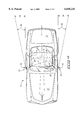
- FIG. 1 is a perspective, environmental view of a mirror assembly of the present invention shown mounted on an overland vehicle of conventional design.
- FIG. 2 is a partial, perspective view of a mirror assembly of the present invention and which would be utilized on the driver's side of an overland vehicle, and which illustrates the luminous image provided by same.
- FIG. 3 is a partial, perspective view of a mirror assembly of the present invention and which would be employed on the passenger side of an overland vehicle, and which illustrates the luminous image which would be provided by same.
- FIG. 4 is a top, plan view of an overland vehicle of conventional design and which illustrates the approximate, projected pattern of light as provided by the mirror assembly of the present invention.
- FIG. 5 is a greatly simplified, exploded, perspective view of the mirror assembly of the present invention.
- FIG. 6 is a greatly enlarged, longitudinal, vertical sectional view of the mirror assembly of the present invention.
- the mirror assembly of the present invention is generally indicated by the numeral 10 in FIG. 1.
- the mirror assembly 10 of the present invention is discussed as would be configured if it were installed on an overland vehicle 11 of conventional design.
- the mirror assembly 10 of the present invention may be mounted on a vehicle, alternatively, in place of the rear view mirror which is located in the passenger compartment, and/or in place of the side view mirrors which are mounted on the exterior surface of the vehicle.
- the mirror assembly 10 of the subject invention will be discussed in greater detail in the paragraphs which follow.
- the mirror assembly 10 is adapted to operate as a combination rear view mirror and visual signaling device, and wherein the visual signal it provides is capable of being seen from locations rearwardly of the overland vehicle 11, and which further cannot be readily seen, under most circumstances, by an operator of the same vehicle.
- the mirror assembly 10 of the present invention is mounted on an overland vehicle 11 of conventional design.
- the overland vehicle has a front or forward portion 12, and a rear portion 13.
- the overland vehicle 11 further has a passenger compartment 14 which includes a front seat 15, and an operator's position 20.
- the overland vehicle 11 also includes locations 21 for a pair of exterior rear view mirrors.
- the overland vehicle 11 also has a hand operated directional signaling switch, and brake, not shown, and which provides a signal which may alert drivers of other vehicles in the immediate vicinity that the overland vehicle 11 is about to change directions, turn, change lanes, stop etc.
- Other signals may also be provided from other devices such as hazard warning switches, and all manner of other signaling devices on the automobile.
- an operator 30, when positioned in the operator's position 20, has a field of view which extends approximately 180 degrees from the operator's position towards the forward portion 12 of the vehicle. Further, and by using a pair of mirror assemblies 10 which are located at the positions 21 on the exterior portion of the vehicle 11, the operator 30 may, by looking along predetermined lines of sight, view areas beyond his normal field of view, and rearwardly of the operator's position 20.
- the operator 30 has a first line of sight 31 which extends from the operator 30 to the mirror assembly 10 which is located on the driver's side of the overland vehicle 11, and which permits the operator to view rearwardly of the vehicle along the driver's side thereof.
- the operator 30 has a second line of sight 32 which extends from the operator 30 to the passenger side of the overland vehicle, and therefore permits the operator to view rearwardly along that side of the vehicle. Furthermore, the operator has a third line of sight which extends from the operator's position 20 to the interior rear view mirror, not shown.
- the mirror assembly 10 of the present invention provides illumination zones 33 which extend rearwardly of the vehicle and substantially out of the line of sight of the operator 30.
- the illumination zones have a predetermined beam spread 34 of not less than about 2 meters when measured at a distance of about 8 meters from the mirror assembly 10. Further, the deviation angle of the driver's side illumination zone, as measured from a line perpendicular to the surface of mirror assembly is about 30%; and the deviation angle for the passenger's side illumination zone is about 25 degrees.
- the illumination zones may be further expanded to include the operators position 20 of the overland vehicle.
- the mirror assembly would be rendered operable to display the hazard warning signal in a fashion whereby it would be readily visible from the operator's position as well as along the zones of illumination discussed above.
- this same hazard warning could be rendered operable to be seen only from the operator's position 20.
- the mirror assembly 10 of the present invention includes a mirror housing 40 which is operable to be mounted at mirror locations 21 on the exterior portion of the overland vehicle 11.
- the mirror housing or enclosure has a rear wall 41 and a sidewall 42 which extends upwardly therefrom.
- the sidewall has a peripheral edge 43 which defines an aperture 44 having given dimensions. Further, a smaller aperture 45 is formed in the sidewall 42.
- the rear wall 41, and sidewall 42 define a cavity 46 which is operable to receive the mirror assembly 10 and other assemblies, such as a bezel, not shown.
- the bezel provides a means by which the accompanying mirror assembly 10 may be movably supported within the housing and then can be adjusted, either manually or remotely, as by motorized actuators, to a given angular orientation relative to the first and second lines of sight 31 and 32. This provides the means by which the operator 30 may adjust his given field of view.
- the bezel has not been illustrated in FIG. 5 to facilitate the understanding of the present invention.
- the mirror assembly 10 of the present invention includes a semitransparent, nondichroic mirror 60 which passes about 1% to about 30% of a broad band of visible light, and which reflects less than about 80% of a broad band of visible light.
- the semitransparent, nondichroic mirror 60 has a front or exterior facing surface 61, and an opposite, rearwardly facing 62.
- the semitransparent mirror 60 further has a peripheral edge 63 which substantially corresponds in shape and size to the aperture 44, and which, when assembled, substantially occludes the aperture 44.
- the semitransparent, nondichroic mirror 60 is formed by depositing a reflective layer of a metal or metal compound selected from group comprising chromium, rhodium, aluminum, and other similar and related substances on one of the surfaces thereof, such as the front surface 61 and wherein the layer has a thickness of about 100 to about 500 Angstroms, and a preferred thickness of about 225 to about 275 Angstroms.
- the semitransparent mirror is fabricated from suitable transparent substrates such as automotive glass, polycarbonate or similar materials.
- the mirror assembly 10 of the present invention includes a light control optical element which is generally designated by the numeral 70.
- the light control optical element 70 has a front surface 71, and an opposite, rearwardly facing surface 72. Further, the light control optical element has a peripheral edge 73 which closely corresponds to the shape of the light assembly, which will be discussed in further detail hereinafter.
- the light control optical element is operable to direct the light being emitted by a light assembly along a given transmission path, outside of the first and second lines of sight 31 and 32 of the operator 30.
- the preferred light control optical element includes a polycarbonate light control film.
- the light control optical element or film is manufactured by the 3M Company under the trade designation "LCF" (light control film).
- This light control optical element is a thin plastic film enclosing a plurality of closely spaced, black colored microlouvers 74.
- the light control film is approximately 0.030 inches (0.75 millimeters) thick and the microlouvers are spaced approximately 0.005 inches apart (0.127 millimeters).
- the microlouvers may be a transparent black or an opaque black and further, the microlouvers may be positioned in various angles to provide a viewing angle, which may include angles as narrow as 48 degrees, plus or minus 6 degrees, or as wide as 90 degrees, plus or minus 15 degrees.
- the light control optical element 70 permits light emitted by the light assembly, which will be discussed hereinafter, to escape along the illumination zones 33, but is further operable to substantially inhibit or block the light emitted by an associated light assembly from traveling along the first and second lines of sight 31 and 32, respectively, and into the view of the operator 30. This is best seen by reference to FIG. 4. Of course, other similar assemblies could be fabricated and used with equal success.
- light emitted by the mirror assembly 10 can be controlled, to a certain degree, by the selective angular orientation of the light assembly, which will be discussed hereinafter.
- the orientation of a light assembly in a predetermined oblique position, which is substantially coaxially aligned with the illumination zones 33 will, under some conditions, eliminate the need for a light control optical element.
- the light control optical element 70 may be completely eliminated, or may further be discontinuous, that is, only a portion of the light assembly, which will be discussed hereinafter, may be covered or otherwise effected by the light control optical element.
- the light control optical element 70 is secured to the rear surface 62 of the semitransparent, nondichroic mirror 60 by any suitable fastening means, including adhesives and the like.
- the light control optical element may also comprise other structures, such as holograms and the like, and which function in a similar fashion to direct the light emitted by a light assembly into the illumination zones 33, as was described above.
- a refractive, or second optical element which may have a total internal reflection portion 80 is positioned immediately rearwardly of the light control optical element 70.
- This refractive optical element, or optical element having total internal reflective portions is operable to bend the light emitted by the light assembly, which will be discussed hereinafter, in an amount of about 20 degrees to about 40 degrees, as measured from a line positioned normal to the front surface 61 of the semitransparent, nondichroic mirror 63.
- the refractive optical element, or optical element having portions which are totally internally reflective 80 provides a convenient means by which the mirror assembly 10 can be readily mounted on overland vehicles 11 which are positioned at various distances above the surface of the earth.
- the mirror assembly 10 was mounted on a tractor-trailer type vehicle, this particular optical element would be adapted to bend the light downwardly such that it could be observed by lower situated passenger vehicles.
- the second optical element 80 would be adapted to direct the light emitted by the light assembly generally upwardly such that it could be observed by an operator of a tractor-trailer or similar vehicle who is sitting somewhat higher above the surface of the earth.
- the refractive optical element, or optical element having portions which are totally internally reflective 80 has a forward surface 81, and an opposite, rearwardly facing surface 82.
- this same optical element 80 has a peripheral edge 83 which is substantially similar in shape to the underlying light control optical element 70 which is adjacent thereto.
- the refractive optical element, and light control optical element 70 are affixed together by conventional fastening means such as adhesives or the like, or may be formed as an integral component.
- Commercially available refractive films may be secured from 3M Company under the trade designation "Prismatic” or “Fresnel” Films.
- a collimating optical element which is generally designated by the numeral 90, is affixed or otherwise positioned on the rear surface 82 of the refractive optical element or optical element having portions which are totally internally reflective 80.
- This same optical element may also be integrally combined with the aforementioned optical elements into a single optical component.
- the collimating optical element has a forward facing surface 91, and an opposite rearward facing surface 92.
- a plurality of cavities 93 are formed in the rear surface 92 and are disposed in a given pattern to receive individual light emitting diodes therein. The light emitting diodes will be discussed in further detail hereinafter. While FIG.
- FIG. 6 illustrates a collimating optical element 90 for use with light emitting diodes
- a collimating optical element may be fabricated for use with other lighting means, and which will operate with equal success.
- the collimating optical element 90 is operable to receive the light emitted by the light assembly and collimate it into a given direction.
- the collimating optical element may have portions which are refractive, reflective, or both.
- the collimating optical element 90 is fastened by conventional means to the rear surface 82 of the refractive optical element or optical element having total internal reflective portions 80, or is made integral therewith, as was noted, above.
- the mirror assembly 10 of the present invention includes a light assembly 100 which is positioned adjacent to the semitransparent mirror 60, and which emits a broad band of visible light which is passed by the semitransparent mirror 60.
- the light assembly 100 comprises at least one light source, but as described hereinafter, the light assembly 100, whatever form it takes, is operable to deliver a luminous intensity of about 1 candela to about 1000 candelas.
- a candela is defined as a unit of luminous intensity which is equal to about 1/60 of the luminous intensity per square centimeter of a black body radiator operating at the temperature of freezing platinum. This was formally known as a candle.
- the resulting mirror assembly has a luminous intensity of about 0.5 to about 120 candelas when this parameter is measured at a location near the front surface 61 of the semitransparent nondichroic mirror 60. Further, when this same parameter is measured at about 8 meters from the mirror assembly the luminous intensity is greater than or equal to about 6 candelas.
- the light assembly 100 is borne by the housing 40 and positioned in the cavity 46 for purposes of emitting a broad band of visible electromagnetic radiation. In the embodiments shown, four alternative light sources are illustrated, and may be used with equal success.
- the invention is not limited to the four light sources discussed herein, but may include other artificial light sources, including light emitting polymers, and which have the functional characteristics which are discussed above. It should be understood that notwithstanding the light assembly 100 selected, the light assembly must be operable to produce a luminous intensity of about 1 candela to about 1000 candelas such that the resulting mirror assembly 10 may have a luminous intensity of about 0.5 to about 120 candelas. Contrary to the prior art teachings which require that the light source selected be substantially matched, that is, emit wavelengths which are substantially identical to the peak wavelengths transmitted by an associated dichroic mirror, the present invention requires no band pass matching. Rather, the semitransparent, nondichroic mirror 60 passes substantially all visible wavelengths in equal amounts.
- the individual light assemblies 100 include first, second, third, fourth, and fifth forms 101, 102, 103, 104, and 105, respectively.
- the first form 101 of the light assembly 100 includes a bank of light emitting diodes; the second form 102 includes a single lamp having a light bulb and reflector; the third form 103 includes a lamp support plate which is adapted to receive a plurality of automotive light bulbs 104; the fourth form of the light assembly 100 may include light sources of various types 110, and a light pipe 111 which is operable to direct the light generated by the various light sources 110 to a predetermined destination within the housing 40; and the fifth form comprises a flat panel illuminator and accompanying light source.
- the first form 101 of the light assembly 100 includes a bank of light emitting diodes (LEDs) which are individually mounted on a support plate or substrate 120.
- the individual light emitting diodes 122 are adapted to produce artificial light having wavelengths which fall within given spectral bands.
- light emitting diodes may be selected which include the 600 through 700 nanometer band and which produce the perceivable color red.
- LED's may also be selected which produce colors such as yellow, green and blue, depending upon the designer's preference.
- LED's which produce individually distinct colors may be grouped together on the support substrate, as in the nature of individual pixels, such that a range of colors may be emitted, as by color mixing, that is, by individually energizing selective light emitting diodes 122 in each of the pixel groupings.
- color mixing that is, by individually energizing selective light emitting diodes 122 in each of the pixel groupings.
- conductive traces 121 are provided on the supporting substrate 120, and are operable to conduct electricity to the individual light emitting diodes 122, which are provided in predetermined patterns to produce the luminous effects as illustrated in FIGS. 2 and 3. Of course many other shapes are possible including alpha-numeric indicia.
- the electricity is provided by means of electrical leads 123 which extend through the aperture 45 formed in the housing 40.
- the electrical leads are coupled to the electrical system of the overland vehicle 11 and may be energized by means of various devices such as the directional signaling switch, and the brakes of the vehicle 11, to name but a few.
- light assembly 100 has a luminous intensity, once energized, of about 1 candela to about 1000 candelas.
- the light assembly has a surface area of about 10 to about 4000 square millimeters. When energized, the light assembly emits energy which is less than about 18 milliwatts per square millimeter of surface area. Further, the luminous intensity of the assembled mirror assembly 10 is about 0.5 to about 120 candelas.
- Light emitting diodes 122 which fit these performance characteristics are manufactured by Hewlett Packard under the trade designation "Polyled". These particular LED's are high efficiency, ultra radiant red and have a narrow viewing angle and a peak wavelength which falls within about 600 to 700 nanometers. It should be understood that each of the individual light emitting diodes 122 have beam centers which are individually oriented in substantially the same direction and are received in the cavities 93 formed in the collimating optical element 90. This is best seen by reference to FIG. 6.
- LED's could be oriented in a fashion whereby their bear centers are directed towards the overland vehicle, or the operator, instead of toward the illumination zones as earlier discussed.
- the operator could be alerted to various changing condition in the vehicle, such as by hazard signals, scrolling warnings, and the like; and simultaneously other LED's could be emitting light, which is seen in the illumination zones, and which could be warning adjacent vehicle operators that the overland vehicle is about to change lanes, slow down, or otherwise change its operating status in some fashion.
- the second form includes a single bulb or lamp 130 which is mounted in, or made integral with a suitable reflector 131.
- This lamp would emit the same wavelengths of light as discussed with the first form, above.
- the lamp 130 would be connected by suitable electrical leads 132 to the signalling assemblies of the overland vehicle 11, such as for example, the braking system and directional signaling system and whereupon applying pressure to the brake pedal or the actuation of the signaling directional switch, the lamp would become energized.
- An appropriate commercial lamp for this purpose is the GE Precise Lamp and which is designated commercially as the MR-16.
- the third form 103 of the light assembly 100 includes a synthetic support plate 140 which supports a plurality of replaceable automotive bulbs 141, such as the model number 882 automotive bulb, which are commercially available nationwide. These lamps similarly would emit the same wavelengths of light as discussed with the first form above.
- the lamp support plate 140 has a plurality of apertures 142 which permits the individual replaceable lamps to be electrically coupled to the lamp support plate.
- the lamp support plate carries suitable etching on the reverse surface (not shown) and which conducts electrical current from appropriate electrical leads 143 to the individual lamps.
- the fourth form 104 of the light assembly 100 includes a light engine having a high intensity discharge lamp; or incandescent; or halogen; or light emitting diode; or laser; or fluorescent; or neon; or other luminous emitter 150 which are individually placed in a predetermined remote location on the overland vehicle 11 relative to the mirror housing 40.
- a light engine having a high intensity discharge lamp; or incandescent; or halogen; or light emitting diode; or laser; or fluorescent; or neon; or other luminous emitter 150 which are individually placed in a predetermined remote location on the overland vehicle 11 relative to the mirror housing 40.
- located in light receiving relation relative to the individual light sources 110 is the receiving end 151 of the optical cable or light pipe 111.
- the fourth form of the light assembly 104 also includes a secondary optical assembly (not shown) and which may be necessary to gather the light from the light source 105 and input or focus it into the receiving end 151. These secondary assemblies, which are not shown, are well understood in the art.
- the light pipe has a remote or discharge end 152 which extends through the aperture 45 and is positioned at a predetermined location internally of the cavity 46.
- the discharge end is secured within the housing 40 in a predetermined location such that light transmitted by the light pipe emanates into the housing and interacts, as appropriate, with the optical assemblies therein.
- Secondary optical assemblies which may be also enclosed within in the housing 40, in addition to those shown herewith, may include assemblies such as fresnel lenses, total internal reflectors, holograms, diffusers, etc.
- the fifth form of the light assembly comprises a flat panel illuminator 170 and suitable lamp 171 11 which is disposed in light emitting relation thereto. As earlier discussed, light emitting polymers may also find application in this invention.
- the first form of the light assembly 120 and optical elements 70, 80, and 90 are normally enclosed within a sealed housing, not shown, such that they are protected from the ambient environment.
- the optical elements 70, 80, and 90, and the first form of light assembly 120 comprise an optical stack 180 which has a given thickness of less than about 25 mm., and a weight of less than about 100 grams. This thickness dimension and weight characteristic allows the present invention to be readily installed on existing exterior mirror designs usually without any or on occasion only slight design modifications to the mirror housings and bezel designs employed with same. Further, these same thickness and weight characteristics do not detract from the performance parameters of these same mirrors.
- the weight characteristic does not cause the existing mirror designs to operate in an unsatisfactory fashion such as when they are subjected to normal vibratory motion, or jarring, which could tend to cause the associated mirror to become periodically displaced, or misaligned and require subsequent operator adjustment.
- the weight of the optical stack 180 if great enough, could potentially cause the underlying mirror to become unbalanced to a point where severe vibratory motion of a given magnitude may cause the mirror to become displaced when exposed to same.
- the invention includes a semitransparent mirror 60 which passes about 1% to about 30% of a broad band of visible light and which reflects less than about 80% of a broad band of visible light; and a light assembly 100 positioned adjacent to the semitransparent mirror 60 and which emits visible light which is passed by the semitransparent mirror, the luminous intensity of the mirror assembly 10 being about 0.5 to about 120 candelas.
- the mirror assembly 10 has a semitransparent mirror 60 which has front and rear surfaces 61 and 62 respectively, and a layer of a metal or metal compound such as chromium, rhodium, aluminum, or the like, and which has a thickness of about 200 to about 350 Angstroms is applied to the front surface thereof.
- the mirror assembly 10 comprises a housing or enclosure 40 which defines an aperture 44, and wherein the light assembly 100 is positioned in the enclosure.
- the mirror assembly 10 includes a collimating optical element 90 which is positioned between the light assembly 100 and the semitransparent mirror 60; and a refractive optical element or an optical element having total internal reflective portions 80 is positioned between the collimating optical element 90 and the rear surface 62 of the semitransparent, nondichroic mirror 60.
- the mirror assembly 10 may further comprise a light control optical element 70 which is positioned between the refractive optical element, or optical element having total internal reflective portions 80 and the semitransparent, nondichroic mirror 60. As seen in FIG. 4, the light control optical element 70 is operable to direct light emitted by the light assembly 100 along given paths of travel and into the illumination zones 33.
- the illumination zones are normally outside the line of sight of the operator 30, thereby providing a convenient means by which an adjacent automobile or observer may be provided with signals regarding the operation of the overland vehicle 11.
- the mirror assembly 10 has a light assembly 100 which comprises at least one light source, but most preferably, comprises about 1 to about 30 light emitting diodes.
- the luminous intensity of the light assembly 100 is about 1 candela to about 1000 candelas.
- the light assembly 100 is operable to emit sufficient luminous intensity such that the mirror assembly 10 has a luminous intensity of about 0.5 to about 120 candelas.
- sufficient light passes through the semitransparent, nondichroic mirror such that a highly functional and visibly discernible signal is provided.
- the present invention is operable to produce not greater than about 18 milliwatts of energy per square millimeter of the surface area of the light assembly 100.
- the mirror assembly 10 of the present invention comprises: a substantially neutrally reflective nondichroic, semitransparent mirror 60 having front and rear surfaces 61 and 62 respectively, and which passes about 1% to about 30% of a broad band of visible light, and wherein the front surface 61 reflects less than about 80% of a broad band of visible light; a light assembly 100 positioned adjacent to s the rear surface of the semitransparent mirror 60 and which emits visible light which is passed by the semitransparent mirror, the light assembly having a luminous intensity of about 1 candela to about 1000 candelas, and the luminous intensity of the mirror assembly 10 being about 0.5 to about 120 candelas, and wherein the light assembly has a surface area of about 10 to about 4000 square mm; a collimating optical element 90 positioned between the light assembly 100 and the rear surface 62 of the semitransparent mirror 60; a refractive optical element, or optical element having total internal reflective portions 80 positioned between the collimating optical element 90, and the rear surface 62 of the semitransparent
- the present invention achieves benefits not provided for in the prior art.
- the present invention avoids the shortcomings and costs associated with the prior art practices of employing a dichroic mirror.
- the present invention thus provides design flexibility, and decreased manufacturing costs not possible heretofore in a mirror assembly which is highly efficient, compact, lightweight and cost effective to manufacture.
- the present mirror assembly 10 is highly reliable in operation and provides superior signaling capability for overland vehicles for various designs.
Abstract
Description
Claims (59)
Priority Applications (7)
| Application Number | Priority Date | Filing Date | Title |
|---|---|---|---|
| US09/123,047 US6045243A (en) | 1996-08-28 | 1998-07-27 | Mirror assembly |
| EP99935924A EP1101063A4 (en) | 1998-07-27 | 1999-07-26 | Mirror assembly |
| BR9911424-0A BR9911424A (en) | 1998-07-27 | 1999-07-26 | Mirror mounting |
| AU51298/99A AU5129899A (en) | 1998-07-27 | 1999-07-26 | Mirror assembly |
| CA002338373A CA2338373C (en) | 1998-07-27 | 1999-07-26 | Mirror assembly |
| PCT/US1999/016897 WO2000006944A1 (en) | 1998-07-27 | 1999-07-26 | Mirror assembly |
| MXPA01001019A MXPA01001019A (en) | 1998-07-27 | 1999-07-26 | Mirror assembly. |
Applications Claiming Priority (2)
| Application Number | Priority Date | Filing Date | Title |
|---|---|---|---|
| US08/704,084 US5788357A (en) | 1996-08-28 | 1996-08-28 | Mirror assembly |
| US09/123,047 US6045243A (en) | 1996-08-28 | 1998-07-27 | Mirror assembly |
Related Parent Applications (1)
| Application Number | Title | Priority Date | Filing Date |
|---|---|---|---|
| US08/704,084 Continuation-In-Part US5788357A (en) | 1996-08-28 | 1996-08-28 | Mirror assembly |
Publications (1)
| Publication Number | Publication Date |
|---|---|
| US6045243A true US6045243A (en) | 2000-04-04 |
Family
ID=22406424
Family Applications (1)
| Application Number | Title | Priority Date | Filing Date |
|---|---|---|---|
| US09/123,047 Expired - Lifetime US6045243A (en) | 1996-08-28 | 1998-07-27 | Mirror assembly |
Country Status (7)
| Country | Link |
|---|---|
| US (1) | US6045243A (en) |
| EP (1) | EP1101063A4 (en) |
| AU (1) | AU5129899A (en) |
| BR (1) | BR9911424A (en) |
| CA (1) | CA2338373C (en) |
| MX (1) | MXPA01001019A (en) |
| WO (1) | WO2000006944A1 (en) |
Cited By (128)
| Publication number | Priority date | Publication date | Assignee | Title |
|---|---|---|---|---|
| US6139171A (en) * | 1998-03-13 | 2000-10-31 | Reitter & Schefenacker Gmbh & Co. Kg | Exterior rearview mirror for vehicles, preferably motor vehicles |
| US6181243B1 (en) * | 1999-11-23 | 2001-01-30 | Tzu Tsan Yang | Auxiliary auto signlight system |
| US6257746B1 (en) * | 1998-11-03 | 2001-07-10 | K. W. Muth Company, Inc. | Signalling assembly |
| US6356376B1 (en) | 1997-04-02 | 2002-03-12 | Gentex Corporation | Electrochromic rearview mirror incorporating a third surface metal reflector and a display/signal light |
| US6416208B2 (en) | 1993-02-01 | 2002-07-09 | Donnelly Corporation | Vehicle exterior mirror system with signal light |
| US6441943B1 (en) | 1997-04-02 | 2002-08-27 | Gentex Corporation | Indicators and illuminators using a semiconductor radiation emitter package |
| US6447128B1 (en) | 2000-07-28 | 2002-09-10 | Lang-Mekra North America Llc | Rearview mirror assembly for a vehicle with monitor |
| US20020154426A1 (en) * | 2001-04-03 | 2002-10-24 | Heinrich Lang | Mirror arrangement for motor vehicles |
| US20020159270A1 (en) * | 2001-01-23 | 2002-10-31 | Lynam Niall R. | Vehicular lighting system |
| US20020171954A1 (en) * | 2001-05-21 | 2002-11-21 | Bonardi Timothy A. | Rearview mirror assembly construction |
| US6568839B1 (en) | 1993-02-01 | 2003-05-27 | Donnelly Corporation | Vehicle exterior mirror system with signal light |
| US6592230B2 (en) | 1997-10-16 | 2003-07-15 | Holland Hitch Company | Truck rearview mirror assembly having a display for displaying trailer coupling status information |
| US6642840B2 (en) | 2000-07-28 | 2003-11-04 | Lang-Mekra North Amicica, Llc | Rearview mirror assembly with monitor |
| US6648477B2 (en) * | 2000-07-06 | 2003-11-18 | Donnelly Corporation | Rearview mirror assembly with information display |
| US20040004841A1 (en) * | 2002-04-10 | 2004-01-08 | Heinrich Lang | Outside mirror with blinker light for vehicles |
| US6700692B2 (en) | 1997-04-02 | 2004-03-02 | Gentex Corporation | Electrochromic rearview mirror assembly incorporating a display/signal light |
| US6709136B2 (en) | 1993-02-01 | 2004-03-23 | Donnelly Corporation | Lighted exterior mirror system |
| US20040080958A1 (en) * | 2002-10-29 | 2004-04-29 | Bukosky Allen A. | Signaling assembly |
| US20040095632A1 (en) * | 2001-05-21 | 2004-05-20 | Busscher Bradley L. | Rearview mirror constructed for efficient assembly |
| US20040145902A1 (en) * | 2003-01-28 | 2004-07-29 | Todd Daniel R. | Heated mirror assembly |
| US20040165398A1 (en) * | 2002-04-15 | 2004-08-26 | Bukosky Allen A. | Signaling assembly |
| US20040184282A1 (en) * | 2003-03-20 | 2004-09-23 | Kazuhiko Nishijima | Mirror assembly with multi-color illumination |
| US20040208015A1 (en) * | 2002-10-03 | 2004-10-21 | Magna Donnelly Mirrors North America, L.L.C. | Vehicle mirror with internal illumination source and transmitting housing |
| US20050007645A1 (en) * | 1999-05-14 | 2005-01-13 | Tonar William L. | Electrochromic rearview mirror incorporating a third surface partially transmissive reflector |
| US20050036328A1 (en) * | 2001-08-31 | 2005-02-17 | Walser Jeremy A. | Vehicle lamp assembly with heat sink |
| US20050099693A1 (en) * | 2003-10-02 | 2005-05-12 | Kenneth Schofield | Mirror reflective element assembly including electronic component |
| US20050110630A1 (en) * | 1993-02-01 | 2005-05-26 | Donnelly Corporation | Vehicle exterior mirror system with turn signal light assembly |
| US20050141229A1 (en) * | 2003-12-24 | 2005-06-30 | Ichikoh Industries, Ltd. | Vehicle mirror assembly that includes light unit |
| US6918685B2 (en) | 2002-04-15 | 2005-07-19 | K. W. Muth Company, Inc. | Mirror with integrated signaling assembly |
| US6926431B1 (en) | 2002-04-09 | 2005-08-09 | Magna Donnelly Mirrors North America, L.L.C. | Vehicular mirror assembly incorporating multifunctional illumination source |
| WO2005098310A1 (en) * | 2004-04-05 | 2005-10-20 | Fico Mirrors, S.A. | Lighting assembly with safety and signalling functions for motor vehicles |
| US20050270789A1 (en) * | 2004-06-03 | 2005-12-08 | Lueftner Robert I | Rearview mirror for a vehicle |
| US20050270620A1 (en) * | 2004-06-08 | 2005-12-08 | Bauer Frederick T | Rearview mirror element having a circuit mounted to the rear surface of the element |
| US20060186314A1 (en) * | 2004-12-30 | 2006-08-24 | Leung Anthony Kit L | Partially transparent mirror having selectively activated light portion |
| US20060215413A1 (en) * | 2005-03-23 | 2006-09-28 | Mathieu Daniel J | Signaling assembly |
| US7140755B2 (en) | 1993-02-01 | 2006-11-28 | Donnelly Corporation | Security lighted exterior rearview mirror system for a vehicle |
| US7195382B1 (en) | 2004-06-30 | 2007-03-27 | Magna Donnelly Mirrors North America, L.L.C. | Vehicle mirror with secondary lighting lens for ground illuminator |
| US20070091631A1 (en) * | 2005-10-25 | 2007-04-26 | K.W. Muth Company, Inc. | Signaling assembly |
| US20070153536A1 (en) * | 2006-01-05 | 2007-07-05 | K.W. Muth Company, Inc. | Signaling assembly |
| US20070171037A1 (en) * | 1998-01-07 | 2007-07-26 | Donnelly Corporation | Video mirror system suitable for use in a vehicle |
| US20080024864A1 (en) * | 2006-07-28 | 2008-01-31 | K.W. Muth Company, Inc. | Signaling assembly |
| US20080030836A1 (en) * | 2006-03-03 | 2008-02-07 | Gentex Corporation | Thin-film coatings, electro-optic elements and assemblies incorporating these elements |
| US20080089082A1 (en) * | 2005-06-27 | 2008-04-17 | Todd Daniel R | Electromagnetic radiation assembly |
| US20080106389A1 (en) * | 2006-11-06 | 2008-05-08 | Donnelly Corporation | Display device for exterior rearview mirror |
| US20080225417A1 (en) * | 2007-03-14 | 2008-09-18 | Visiocorp Patents S.A.R.I | Rearview Mirror With Illuminated Area |
| US20080302657A1 (en) * | 2007-03-05 | 2008-12-11 | Gentex Corporation | Method and Apparatus for Ion Milling |
| US20080310005A1 (en) * | 2006-12-07 | 2008-12-18 | Tonar William L | Thin-Film Coatings, Electro-Optic Elements and Assemblies Incorporating These Elements |
| US7492281B2 (en) | 2005-07-06 | 2009-02-17 | Donnelly Corporation | Vehicle exterior mirror assembly with blind spot indicator |
| US20090207513A1 (en) * | 2007-03-05 | 2009-08-20 | Gentex Corporation | Multi-Zone Mirrors |
| US20090251910A1 (en) * | 2007-12-27 | 2009-10-08 | Steven Feit | Head unit background illumination |
| US7667579B2 (en) | 1998-02-18 | 2010-02-23 | Donnelly Corporation | Interior mirror system |
| US7711479B2 (en) | 2000-03-02 | 2010-05-04 | Donnelly Corporation | Rearview assembly with display |
| US7717596B1 (en) | 2005-07-15 | 2010-05-18 | Alan Bell | Rearview mirror assembly with running lights |
| US7728721B2 (en) | 1998-01-07 | 2010-06-01 | Donnelly Corporation | Accessory system suitable for use in a vehicle |
| US7771061B2 (en) | 1994-05-05 | 2010-08-10 | Donnelly Corporation | Display mirror assembly suitable for use in a vehicle |
| US7815326B2 (en) | 2002-06-06 | 2010-10-19 | Donnelly Corporation | Interior rearview mirror system |
| US7821697B2 (en) | 1994-05-05 | 2010-10-26 | Donnelly Corporation | Exterior reflective mirror element for a vehicular rearview mirror assembly |
| US7826123B2 (en) | 2002-09-20 | 2010-11-02 | Donnelly Corporation | Vehicular interior electrochromic rearview mirror assembly |
| US7830583B2 (en) | 2006-03-03 | 2010-11-09 | Gentex Corporation | Electro-optical element including IMI coatings |
| US7832882B2 (en) | 2002-06-06 | 2010-11-16 | Donnelly Corporation | Information mirror system |
| US20100290225A1 (en) * | 2000-05-08 | 2010-11-18 | Alexander Rizkin | Highly efficient luminaire having optical transformer providing precalculated angular intensity distribution and method therefore |
| US7855755B2 (en) | 2005-11-01 | 2010-12-21 | Donnelly Corporation | Interior rearview mirror assembly with display |
| US7859737B2 (en) | 2002-09-20 | 2010-12-28 | Donnelly Corporation | Interior rearview mirror system for a vehicle |
| US7864399B2 (en) | 2002-09-20 | 2011-01-04 | Donnelly Corporation | Reflective mirror assembly |
| US7864398B2 (en) | 2004-06-08 | 2011-01-04 | Gentex Corporation | Electro-optical element including metallic films and methods for applying the same |
| US20110002028A1 (en) * | 2006-03-03 | 2011-01-06 | Gentex Corporation | Thin-Film Coatings, Electro-Optic Elements and Assemblies Incorporating These Elements |
| US7888629B2 (en) | 1998-01-07 | 2011-02-15 | Donnelly Corporation | Vehicular accessory mounting system with a forwardly-viewing camera |
| US7906756B2 (en) | 2002-05-03 | 2011-03-15 | Donnelly Corporation | Vehicle rearview mirror system |
| US7914188B2 (en) | 1997-08-25 | 2011-03-29 | Donnelly Corporation | Interior rearview mirror system for a vehicle |
| US20110075420A1 (en) * | 2008-06-10 | 2011-03-31 | Koninklijke Philips Electronics N.V. | Light output device and method |
| US20110080629A1 (en) * | 2006-03-03 | 2011-04-07 | Gentex Corporation | Electro-optical element including imi coatings |
| US7926960B2 (en) | 1999-11-24 | 2011-04-19 | Donnelly Corporation | Interior rearview mirror system for vehicle |
| US20110185609A1 (en) * | 2010-02-04 | 2011-08-04 | Cse, Inc. | Compact led light module |
| US8019505B2 (en) | 2003-10-14 | 2011-09-13 | Donnelly Corporation | Vehicle information display |
| US8049640B2 (en) | 2003-05-19 | 2011-11-01 | Donnelly Corporation | Mirror assembly for vehicle |
| US8058977B2 (en) | 2006-10-24 | 2011-11-15 | Donnelly Corporation | Exterior mirror having a display that can be viewed by a host driver or drivers of other vehicles |
| US8066415B2 (en) | 1999-06-17 | 2011-11-29 | Magna Mirrors Of America, Inc. | Exterior mirror vision system for a vehicle |
| US8083386B2 (en) | 2001-01-23 | 2011-12-27 | Donnelly Corporation | Interior rearview mirror assembly with display device |
| US8154418B2 (en) | 2008-03-31 | 2012-04-10 | Magna Mirrors Of America, Inc. | Interior rearview mirror system |
| US8169681B2 (en) | 2006-03-03 | 2012-05-01 | Gentex Corporation | Thin-film coatings, electro-optic elements and assemblies incorporating these elements |
| US8194133B2 (en) | 2000-03-02 | 2012-06-05 | Donnelly Corporation | Vehicular video mirror system |
| US8228590B2 (en) | 2010-08-09 | 2012-07-24 | Gentex Corporation | Electro-optic system configured to reduce a perceived color change |
| DE102012005651A1 (en) | 2011-04-07 | 2012-10-11 | Magna Mirrors Holding Gmbh | Vehicle extrior mirror for use with integrated display device, particularly lane changing display device, comprises housing and mirror glass arranged on mirror glass carrier, where display device is provided with lighting unit |
| US8288711B2 (en) | 1998-01-07 | 2012-10-16 | Donnelly Corporation | Interior rearview mirror system with forwardly-viewing camera and a control |
| US8294975B2 (en) | 1997-08-25 | 2012-10-23 | Donnelly Corporation | Automotive rearview mirror assembly |
| US8305235B2 (en) | 2007-11-05 | 2012-11-06 | Magna Mirrors Of America, Inc. | Exterior mirror reflective element sub-assembly with signal indicator |
| US8449158B2 (en) | 1995-04-21 | 2013-05-28 | Magna Mirrors Of America, Inc. | Vehicle exterior mirror system |
| US8462204B2 (en) | 1995-05-22 | 2013-06-11 | Donnelly Corporation | Vehicular vision system |
| US8503062B2 (en) | 2005-05-16 | 2013-08-06 | Donnelly Corporation | Rearview mirror element assembly for vehicle |
| US8525703B2 (en) | 1998-04-08 | 2013-09-03 | Donnelly Corporation | Interior rearview mirror system |
| US8649083B2 (en) | 2007-03-05 | 2014-02-11 | Gentex Corporation | Multi-zone mirrors |
| US8708536B1 (en) | 2010-08-30 | 2014-04-29 | K.W. Muth Company, Inc. | Optic assembly for mirror |
| US8801245B2 (en) | 2011-11-14 | 2014-08-12 | Magna Mirrors Of America, Inc. | Illumination module for vehicle |
| US8964278B2 (en) | 2010-08-09 | 2015-02-24 | Gentex Corporation | Electro-optic system configured to reduce a perceived color change |
| US9019091B2 (en) | 1999-11-24 | 2015-04-28 | Donnelly Corporation | Interior rearview mirror system |
| US9200775B2 (en) | 2009-04-24 | 2015-12-01 | 3M Innovative Properties Company | Light assembly |
| US9274394B2 (en) | 2007-03-05 | 2016-03-01 | Gentex Corporation | Multi-zone mirrors |
| US9346403B2 (en) | 2009-10-07 | 2016-05-24 | Magna Mirrors Of America, Inc. | Rearview mirror assembly |
| US9440580B2 (en) | 2011-11-23 | 2016-09-13 | Muth Mirror Systems, Llc | Optic assembly having virtual external common focus |
| US9475431B2 (en) | 2011-10-05 | 2016-10-25 | Magna Mirrors Of America, Inc. | Rearview mirror assembly |
| US9487144B2 (en) | 2008-10-16 | 2016-11-08 | Magna Mirrors Of America, Inc. | Interior mirror assembly with display |
| US9488892B2 (en) | 2013-01-09 | 2016-11-08 | Gentex Corporation | Printed appliqué and method thereof |
| WO2016178190A1 (en) | 2015-05-06 | 2016-11-10 | Magna Mirrors Of America, Inc. | Vehicle vision system with blind zone display and alert system |
| US9586526B2 (en) | 1995-04-21 | 2017-03-07 | Magna Mirrors Of America, Inc. | Vehicle exterior mirror system |
| US20170080874A1 (en) * | 2011-09-08 | 2017-03-23 | Golight, Inc. | Rotatable optical device housing and mounting platform |
| US9634206B1 (en) | 2015-04-30 | 2017-04-25 | Cse, Inc. | LED luminaire |
| US9659498B2 (en) | 2015-09-28 | 2017-05-23 | Magna Mirrors Of America, Inc. | Exterior mirror assembly with blind zone indicator |
| US9663027B2 (en) | 2014-02-19 | 2017-05-30 | Fico Mirrors, S.A. | Exterior rear view mirror assembly for a motor vehicle |
| US9761144B2 (en) | 2014-09-11 | 2017-09-12 | Magna Mirrors Of America, Inc. | Exterior mirror with blind zone indicator |
| US9815409B2 (en) | 2013-05-09 | 2017-11-14 | Magna Mirrors Of America, Inc. | Rearview vision system for vehicle |
| US10166924B2 (en) | 2016-05-11 | 2019-01-01 | Magna Mirrors Of America, Inc. | Vehicle vision system with display by a mirror |
| US10261648B2 (en) | 2009-10-07 | 2019-04-16 | Magna Mirrors Of America, Inc. | Exterior rearview mirror assembly |
| US10442360B2 (en) | 2017-03-02 | 2019-10-15 | Magna Mirrors Of America, Inc. | Interior rearview mirror assembly with display and tilt mechanism |
| WO2020214524A1 (en) | 2019-04-16 | 2020-10-22 | Muth Mirror Systems, Llc | Mirror assembly for autonomous maneuvers |
| US10836315B2 (en) | 2017-11-06 | 2020-11-17 | Magna Mirrors Of America, Inc. | Mirror display system with blind spot display |
| US11214199B2 (en) | 2019-06-03 | 2022-01-04 | Magna Mirrors Of America, Inc. | Interior rearview mirror assembly with display and tilt mechanism |
| US11235699B2 (en) | 2014-02-07 | 2022-02-01 | Magna Mirrors Of America, Inc. | Illumination module for vehicle |
| US11242009B2 (en) | 2005-07-06 | 2022-02-08 | Donnelly Corporation | Vehicular exterior mirror system with blind spot indicator |
| US11242008B2 (en) | 2020-02-07 | 2022-02-08 | Magna Mirrors Of America, Inc. | Vehicular vision system with center stack display and mirror display for surround view and CMS cameras |
| US11498494B2 (en) | 2019-11-27 | 2022-11-15 | Magna Electronics Inc. | Vehicular camera monitoring system |
| US11498487B2 (en) | 2005-07-06 | 2022-11-15 | Magna Mirrors Of America, Inc. | Vehicular exterior mirror system with blind spot indicator |
| US11498486B2 (en) | 2009-10-07 | 2022-11-15 | Magna Mirrors Of America, Inc. | Vehicular exterior rearview mirror assembly |
| US11572018B2 (en) | 2019-12-27 | 2023-02-07 | Magna Mirrors Of America, Inc. | Vehicular exterior mirror assembly with blind zone indicator including anti-backout connector |
| EP4177109A1 (en) * | 2021-11-08 | 2023-05-10 | Hyundai Motor Company | Backlight unit for blind spot warning lighting |
| US11851080B2 (en) | 2021-02-03 | 2023-12-26 | Magna Mirrors Of America, Inc. | Vehicular driver monitoring system with posture detection and alert |
| US11884216B2 (en) | 2020-10-16 | 2024-01-30 | Magna Mirrors Of America, Inc. | Vehicular full mirror display system with auxiliary forward and rearward views |
| US11890991B2 (en) | 2006-10-24 | 2024-02-06 | Magna Mirrors Of America, Inc. | Vehicular exterior rearview mirror assembly with blind spot indicator element |
| US11958414B2 (en) | 2022-05-06 | 2024-04-16 | Magna Mirrors Of America, Inc. | Full mirror display utilizing a trailer camera |
Families Citing this family (3)
| Publication number | Priority date | Publication date | Assignee | Title |
|---|---|---|---|---|
| US7452113B2 (en) * | 2004-03-09 | 2008-11-18 | Gentex Corporation | Optics for controlling the direction of light rays and assemblies incorporating the optics |
| EP2463154B1 (en) | 2010-12-10 | 2016-03-23 | SMR Patents S.à.r.l. | Illuminated display behind the mirror glass of a vehicle's exterior rear view mirror |
| DE102017130347A1 (en) | 2017-12-18 | 2019-06-19 | Motherson Innovations Company Limited | Luminaire and rearview device and motor vehicle with light |
Citations (90)
| Publication number | Priority date | Publication date | Assignee | Title |
|---|---|---|---|---|
| US2060401A (en) * | 1935-05-25 | 1936-11-10 | Joseph C Smith | Direction signal |
| US2180610A (en) * | 1937-04-28 | 1939-11-21 | Oliver C Ritz-Woller | Combination truck mirror and clearance lamp device |
| US2190123A (en) * | 1938-07-02 | 1940-02-13 | Stephen C Pace | Lighting signal |
| US2263382A (en) * | 1939-06-19 | 1941-11-18 | Gotzinger George | Mirror signal |
| US2580014A (en) * | 1949-09-13 | 1951-12-25 | Gazda Antoine | Combined rearview mirror and direction indicating device |
| US2595331A (en) * | 1950-01-30 | 1952-05-06 | Paul F Calihan | Combination vision mirror and signaling device |
| US3040207A (en) * | 1959-11-06 | 1962-06-19 | Signal Stat Corp | Variable intensity automotive vehicle lighting and signalling system |
| US3266016A (en) * | 1964-08-06 | 1966-08-09 | Maru Sho | Outside signal for automobiles |
| US3436758A (en) * | 1967-02-23 | 1969-04-01 | Klaus Kluth | Vehicular warning device having spring positioned reflecting member |
| US3449626A (en) * | 1965-02-16 | 1969-06-10 | Renault | Control mechanisms for flashing lights,especially for direction indicator lights for motor vehicles |
| US3532871A (en) * | 1968-05-20 | 1970-10-06 | Ford Motor Co | Combination running light-reflector |
| US3543018A (en) * | 1968-08-06 | 1970-11-24 | Gen Motors Corp | Rearview mirror with map light |
| US3665392A (en) * | 1970-08-24 | 1972-05-23 | John T Annas | Vehicle driver-actuated safety signal light assembly |
| US3840851A (en) * | 1972-06-30 | 1974-10-08 | Emihus Microcomponents Ltd | Vehicle signal lighting systems |
| US4005928A (en) * | 1971-06-01 | 1977-02-01 | Texas Instruments Incorporated | Nematic liquid crystal displays for low voltage direct current operation |
| US4023029A (en) * | 1975-10-28 | 1977-05-10 | Fischer Kenneth J | Distance indicating mirror device |
| US4040726A (en) * | 1976-03-12 | 1977-08-09 | Paca Francis B | See-through mirror with spaced reflective strips |
| US4066332A (en) * | 1975-01-24 | 1978-01-03 | Fuji Photo Film Co., Ltd. | Rear projection screens |
| US4158483A (en) * | 1975-07-09 | 1979-06-19 | Harman International Industries, Inc. | Remote controlled rearview mirror |
| US4274078A (en) * | 1978-05-22 | 1981-06-16 | Nissan Motor Company, Limited | Mirror assembly with indicator |
| US4299444A (en) * | 1979-08-25 | 1981-11-10 | Vdo Adolf Schindling Ag | Dimmable rear view mirror, particularly for automotive vehicles |
| US4443057A (en) * | 1981-06-01 | 1984-04-17 | Gentex Corporation | Automatic rearview mirror for automotive vehicles |
| US4463411A (en) * | 1981-01-06 | 1984-07-31 | Proctor Ronald A | Supplementary upper brake light |
| US4475100A (en) * | 1982-02-22 | 1984-10-02 | Duh Ching Jeng | Side mirror with indicator light |
| US4479172A (en) * | 1981-11-13 | 1984-10-23 | Clearplas Ltd | Illuminated mirror assembly |
| US4491390A (en) * | 1982-05-06 | 1985-01-01 | Tong Shen Hsieh | Automatic liquid-crystal light shutter |
| US4499451A (en) * | 1981-04-07 | 1985-02-12 | Nippondenso Co., Ltd. | Mirror |
| US4506315A (en) * | 1982-12-08 | 1985-03-19 | Ichikoh Industries, Ltd. | Vehicle headlamp |
| US4516197A (en) * | 1984-08-09 | 1985-05-07 | Yonkers Edward H | Antiglare panel |
| US4583155A (en) * | 1984-09-04 | 1986-04-15 | Hart Robert L | Side mounted rear view mirror with brake light |
| US4588267A (en) * | 1984-01-18 | 1986-05-13 | Ronald Pastore | Combination rear view mirror and digital clock |
| US4591954A (en) * | 1984-04-06 | 1986-05-27 | Stanley Electric Co., Ltd. | Lamp device for a vehicle mounted on a rear window or the like |
| US4603946A (en) * | 1982-09-29 | 1986-08-05 | Kabushiki Kaisha Tokai Rika Denki Seisakusho | Reflection controllable view mirror device for motor vehicle or the like |
| US4613791A (en) * | 1984-02-02 | 1986-09-23 | Honda Motor Co., Ltd. | Automatic light control apparatus for vehicle |
| US4623222A (en) * | 1983-11-14 | 1986-11-18 | Nippondenso Co., Ltd. | Liquid crystal type dazzle-free transmissive-reflective mirror |
| US4626967A (en) * | 1984-03-15 | 1986-12-02 | Nissan Motor Co., Ltd. | Auxiliary lamp arrangement for automotive vehicle or the like |
| US4630904A (en) * | 1985-01-22 | 1986-12-23 | Ronald Pastore | Combination rear view mirror and digital displays |
| US4641442A (en) * | 1985-03-05 | 1987-02-10 | Development Finance Corporation Of New Zealand, Limited | Display units |
| US4646210A (en) * | 1984-06-20 | 1987-02-24 | Donnelly Corporation | Vehicular mirror and light assembly |
| US4659967A (en) * | 1985-07-29 | 1987-04-21 | Motorola Inc. | Modulation circuit for a light emitting device |
| US4665321A (en) * | 1985-08-14 | 1987-05-12 | Kwangling Chang | Automatic control system for automobile lights |
| US4701022A (en) * | 1984-11-28 | 1987-10-20 | C-D Marketing, Ltd. | Day/night mirror |
| US4721364A (en) * | 1983-12-29 | 1988-01-26 | Nippondenso Co., Ltd. | Dazzle-free mirror with photocell in a non-dazzle-free portion |
| US4733335A (en) * | 1984-12-28 | 1988-03-22 | Koito Manufacturing Co., Ltd. | Vehicular lamp |
| US4733336A (en) * | 1986-06-26 | 1988-03-22 | Donnelly Corporation | Lighted/information case assembly for rearview mirrors |
| US4791534A (en) * | 1987-08-07 | 1988-12-13 | Lindberg Victor L | Vehicle including substantially transparent high mounted stop light |
| US4793690A (en) * | 1986-07-18 | 1988-12-27 | Donnelly Corporation | Rearview mirror control circuit |
| US4799768A (en) * | 1987-04-27 | 1989-01-24 | Donnelly Corporation | Automatic rearview mirror with filtered light sensors |
| US4807096A (en) * | 1986-06-26 | 1989-02-21 | Donnelly Corporation | Interior light/carrier module for vehicles |
| US4841198A (en) * | 1987-10-19 | 1989-06-20 | Nartron Corporation | Head lamp control method and apparatus, with PWM output regulation |
| US4862330A (en) * | 1987-09-21 | 1989-08-29 | Koito Manufacturing Co., Ltd. | Vehicle lamp |
| US4868459A (en) * | 1986-08-09 | 1989-09-19 | U.S. Philips Corporation | Method of and circuit for brightness and temperature-dependent control of an LCD illuminator |
| US4868719A (en) * | 1988-02-02 | 1989-09-19 | Stanley Electric Co., Ltd. | Rear combination lamp assembly for vehicles |
| US4882565A (en) * | 1988-03-02 | 1989-11-21 | Donnelly Corporation | Information display for rearview mirrors |
| US4886960A (en) * | 1987-04-08 | 1989-12-12 | Donnelly Mirrors Limited | Control circuit for an automatic rearview mirror |
| US4893063A (en) * | 1987-10-06 | 1990-01-09 | Joseph Pernyeszi | Apparatus for improving the efficiency of a lighting element |
| US4916430A (en) * | 1988-11-03 | 1990-04-10 | Vu Thuan D | Back up rear view mirror light |
| US4917477A (en) * | 1987-04-06 | 1990-04-17 | Gentex Corporation | Automatic rearview mirror system for automotive vehicles |
| US4929866A (en) * | 1987-11-17 | 1990-05-29 | Mitsubishi Cable Industries, Ltd. | Light emitting diode lamp |
| US4935665A (en) * | 1987-12-24 | 1990-06-19 | Mitsubishi Cable Industries Ltd. | Light emitting diode lamp |
| US4951179A (en) * | 1988-08-02 | 1990-08-21 | Koito Manufacturing Co., Ltd. | Lighting device for vehicle |
| US5014167A (en) * | 1990-02-20 | 1991-05-07 | K. W. Muth Company, Inc. | Visual signaling apparatus |
| US5029060A (en) * | 1990-07-17 | 1991-07-02 | Minnesota Mining And Manufacturing Company | Uniform intensity profile catadioptric lens |
| US5050051A (en) * | 1989-01-31 | 1991-09-17 | Koito Manufacturing Co., Ltd. | Automobile signal lamp |
| US5059015A (en) * | 1990-07-20 | 1991-10-22 | Tran Donald Q | Vehicular signal mirror apparatus |
| US5072340A (en) * | 1991-03-25 | 1991-12-10 | Isiah Jones | Signal lamps visible to driver |
| US5093768A (en) * | 1989-10-27 | 1992-03-03 | Stanley Electric Co., Ltd. | Signal lamp composed of light emitting diodes for vehicle |
| US5097395A (en) * | 1989-02-24 | 1992-03-17 | Minnesota Mining And Manufacturing Company | Multiple cavity light fixture |
| US5150966A (en) * | 1990-09-19 | 1992-09-29 | Minnesota Mining And Manufacturing Company | Uniform intensity profile catadioptric lens |
| US5165772A (en) * | 1992-03-18 | 1992-11-24 | Hughes Aircraft Company | Visual display device |
| US5174649A (en) * | 1991-07-17 | 1992-12-29 | Precision Solar Controls Inc. | Led lamp including refractive lens element |
| US5189537A (en) * | 1991-01-28 | 1993-02-23 | Donnelly Corporation | Indicia display for electro-optic devices wherein the indicia comprises a dielectric material extending at least partially into the electro-optic medium |
| US5211466A (en) * | 1992-06-15 | 1993-05-18 | Ford Motor Company | Vehicle rear signal light assembly of the high mounted type |
| US5241457A (en) * | 1991-01-18 | 1993-08-31 | Nippon Sheet Glass Co., Ltd. | Rear window stop lamp for motor vehicles |
| US5272602A (en) * | 1991-04-26 | 1993-12-21 | Nippon Sheet Glass Co., Ltd. | Device for mounting a supplemental stop lamp or the like to a windowpane with ease of connection to a power supply |
| US5285060A (en) * | 1992-12-15 | 1994-02-08 | Donnelly Corporation | Display for automatic rearview mirror |
| US5303130A (en) * | 1992-12-28 | 1994-04-12 | Wei Yung Feng | Illuminating automobile sideview mirror |
| US5355284A (en) * | 1990-02-20 | 1994-10-11 | K. W. Muth Company, Inc. | Mirror assembly |
| US5361190A (en) * | 1990-02-20 | 1994-11-01 | K. W. Muth Co. Inc. | Mirror assembly |
| US5371659A (en) * | 1993-02-01 | 1994-12-06 | Donnelly Corporation | Remote-actuated exterior vehicle security light |
| US5388035A (en) * | 1993-07-23 | 1995-02-07 | Federal-Mogul Corporation | Automotive marker lamp |
| US5402103A (en) * | 1991-06-13 | 1995-03-28 | Tadao Tashiro | Automotive winker device |
| US5404869A (en) * | 1992-04-16 | 1995-04-11 | Tir Technologies, Inc. | Faceted totally internally reflecting lens with individually curved faces on facets |
| US5436741A (en) * | 1993-12-28 | 1995-07-25 | Harman Automotive, Inc. | Holographic signaling mirror |
| US5436809A (en) * | 1992-11-02 | 1995-07-25 | Valeo Vision | Indicating light unit having modular luminous elements, for a motor vehicle |
| US5438487A (en) * | 1992-12-19 | 1995-08-01 | Robert Bosch Gmbh | Light device for vehicles |
| US5481409A (en) * | 1990-02-20 | 1996-01-02 | K. W. Muth Company, Inc. | Mirror assembly |
| US5497306A (en) * | 1993-02-01 | 1996-03-05 | Donnelly Corporation | Exterior vehicle security light |
| US5528422A (en) * | 1993-12-07 | 1996-06-18 | K. W. Muth Company, Inc. | Mirror coating |
| US5575552A (en) * | 1994-12-09 | 1996-11-19 | United Technologies Automotive Systems, Inc. | Lighted mirror apparatus |
Family Cites Families (3)
| Publication number | Priority date | Publication date | Assignee | Title |
|---|---|---|---|---|
| US4461442A (en) * | 1982-09-30 | 1984-07-24 | Keenan E Dale | Holster holder for bed |
| DE4036511A1 (en) | 1990-11-16 | 1992-05-21 | Basf Ag | METHOD FOR PRODUCING EPOXIES |
| US5788357A (en) * | 1996-08-28 | 1998-08-04 | K. W. Muth Company, Inc. | Mirror assembly |
-
1998
- 1998-07-27 US US09/123,047 patent/US6045243A/en not_active Expired - Lifetime
-
1999
- 1999-07-26 MX MXPA01001019A patent/MXPA01001019A/en not_active IP Right Cessation
- 1999-07-26 AU AU51298/99A patent/AU5129899A/en not_active Abandoned
- 1999-07-26 BR BR9911424-0A patent/BR9911424A/en not_active IP Right Cessation
- 1999-07-26 EP EP99935924A patent/EP1101063A4/en not_active Withdrawn
- 1999-07-26 CA CA002338373A patent/CA2338373C/en not_active Expired - Fee Related
- 1999-07-26 WO PCT/US1999/016897 patent/WO2000006944A1/en active Application Filing
Patent Citations (93)
| Publication number | Priority date | Publication date | Assignee | Title |
|---|---|---|---|---|
| US2060401A (en) * | 1935-05-25 | 1936-11-10 | Joseph C Smith | Direction signal |
| US2180610A (en) * | 1937-04-28 | 1939-11-21 | Oliver C Ritz-Woller | Combination truck mirror and clearance lamp device |
| US2190123A (en) * | 1938-07-02 | 1940-02-13 | Stephen C Pace | Lighting signal |
| US2263382A (en) * | 1939-06-19 | 1941-11-18 | Gotzinger George | Mirror signal |
| US2580014A (en) * | 1949-09-13 | 1951-12-25 | Gazda Antoine | Combined rearview mirror and direction indicating device |
| US2595331A (en) * | 1950-01-30 | 1952-05-06 | Paul F Calihan | Combination vision mirror and signaling device |
| US3040207A (en) * | 1959-11-06 | 1962-06-19 | Signal Stat Corp | Variable intensity automotive vehicle lighting and signalling system |
| US3266016A (en) * | 1964-08-06 | 1966-08-09 | Maru Sho | Outside signal for automobiles |
| US3449626A (en) * | 1965-02-16 | 1969-06-10 | Renault | Control mechanisms for flashing lights,especially for direction indicator lights for motor vehicles |
| US3436758A (en) * | 1967-02-23 | 1969-04-01 | Klaus Kluth | Vehicular warning device having spring positioned reflecting member |
| US3532871A (en) * | 1968-05-20 | 1970-10-06 | Ford Motor Co | Combination running light-reflector |
| US3543018A (en) * | 1968-08-06 | 1970-11-24 | Gen Motors Corp | Rearview mirror with map light |
| US3665392A (en) * | 1970-08-24 | 1972-05-23 | John T Annas | Vehicle driver-actuated safety signal light assembly |
| US4005928A (en) * | 1971-06-01 | 1977-02-01 | Texas Instruments Incorporated | Nematic liquid crystal displays for low voltage direct current operation |
| US3840851A (en) * | 1972-06-30 | 1974-10-08 | Emihus Microcomponents Ltd | Vehicle signal lighting systems |
| US4066332A (en) * | 1975-01-24 | 1978-01-03 | Fuji Photo Film Co., Ltd. | Rear projection screens |
| US4158483A (en) * | 1975-07-09 | 1979-06-19 | Harman International Industries, Inc. | Remote controlled rearview mirror |
| US4023029A (en) * | 1975-10-28 | 1977-05-10 | Fischer Kenneth J | Distance indicating mirror device |
| US4040726A (en) * | 1976-03-12 | 1977-08-09 | Paca Francis B | See-through mirror with spaced reflective strips |
| US4274078A (en) * | 1978-05-22 | 1981-06-16 | Nissan Motor Company, Limited | Mirror assembly with indicator |
| US4299444A (en) * | 1979-08-25 | 1981-11-10 | Vdo Adolf Schindling Ag | Dimmable rear view mirror, particularly for automotive vehicles |
| US4463411A (en) * | 1981-01-06 | 1984-07-31 | Proctor Ronald A | Supplementary upper brake light |
| US4499451A (en) * | 1981-04-07 | 1985-02-12 | Nippondenso Co., Ltd. | Mirror |
| US4443057A (en) * | 1981-06-01 | 1984-04-17 | Gentex Corporation | Automatic rearview mirror for automotive vehicles |
| US4479172A (en) * | 1981-11-13 | 1984-10-23 | Clearplas Ltd | Illuminated mirror assembly |
| US4475100A (en) * | 1982-02-22 | 1984-10-02 | Duh Ching Jeng | Side mirror with indicator light |
| US4491390A (en) * | 1982-05-06 | 1985-01-01 | Tong Shen Hsieh | Automatic liquid-crystal light shutter |
| US4603946A (en) * | 1982-09-29 | 1986-08-05 | Kabushiki Kaisha Tokai Rika Denki Seisakusho | Reflection controllable view mirror device for motor vehicle or the like |
| US4506315A (en) * | 1982-12-08 | 1985-03-19 | Ichikoh Industries, Ltd. | Vehicle headlamp |
| US4623222A (en) * | 1983-11-14 | 1986-11-18 | Nippondenso Co., Ltd. | Liquid crystal type dazzle-free transmissive-reflective mirror |
| US4721364A (en) * | 1983-12-29 | 1988-01-26 | Nippondenso Co., Ltd. | Dazzle-free mirror with photocell in a non-dazzle-free portion |
| US4588267A (en) * | 1984-01-18 | 1986-05-13 | Ronald Pastore | Combination rear view mirror and digital clock |
| US4613791A (en) * | 1984-02-02 | 1986-09-23 | Honda Motor Co., Ltd. | Automatic light control apparatus for vehicle |
| US4626967A (en) * | 1984-03-15 | 1986-12-02 | Nissan Motor Co., Ltd. | Auxiliary lamp arrangement for automotive vehicle or the like |
| US4591954A (en) * | 1984-04-06 | 1986-05-27 | Stanley Electric Co., Ltd. | Lamp device for a vehicle mounted on a rear window or the like |
| US4646210A (en) * | 1984-06-20 | 1987-02-24 | Donnelly Corporation | Vehicular mirror and light assembly |
| US4516197A (en) * | 1984-08-09 | 1985-05-07 | Yonkers Edward H | Antiglare panel |
| US4583155A (en) * | 1984-09-04 | 1986-04-15 | Hart Robert L | Side mounted rear view mirror with brake light |
| US4701022A (en) * | 1984-11-28 | 1987-10-20 | C-D Marketing, Ltd. | Day/night mirror |
| US4733335A (en) * | 1984-12-28 | 1988-03-22 | Koito Manufacturing Co., Ltd. | Vehicular lamp |
| US4630904A (en) * | 1985-01-22 | 1986-12-23 | Ronald Pastore | Combination rear view mirror and digital displays |
| US4641442A (en) * | 1985-03-05 | 1987-02-10 | Development Finance Corporation Of New Zealand, Limited | Display units |
| US4659967A (en) * | 1985-07-29 | 1987-04-21 | Motorola Inc. | Modulation circuit for a light emitting device |
| US4665321A (en) * | 1985-08-14 | 1987-05-12 | Kwangling Chang | Automatic control system for automobile lights |
| US4733336A (en) * | 1986-06-26 | 1988-03-22 | Donnelly Corporation | Lighted/information case assembly for rearview mirrors |
| US4807096A (en) * | 1986-06-26 | 1989-02-21 | Donnelly Corporation | Interior light/carrier module for vehicles |
| US4793690A (en) * | 1986-07-18 | 1988-12-27 | Donnelly Corporation | Rearview mirror control circuit |
| US4868459A (en) * | 1986-08-09 | 1989-09-19 | U.S. Philips Corporation | Method of and circuit for brightness and temperature-dependent control of an LCD illuminator |
| US4917477A (en) * | 1987-04-06 | 1990-04-17 | Gentex Corporation | Automatic rearview mirror system for automotive vehicles |
| US4886960A (en) * | 1987-04-08 | 1989-12-12 | Donnelly Mirrors Limited | Control circuit for an automatic rearview mirror |
| US4799768A (en) * | 1987-04-27 | 1989-01-24 | Donnelly Corporation | Automatic rearview mirror with filtered light sensors |
| US4791534A (en) * | 1987-08-07 | 1988-12-13 | Lindberg Victor L | Vehicle including substantially transparent high mounted stop light |
| US4862330A (en) * | 1987-09-21 | 1989-08-29 | Koito Manufacturing Co., Ltd. | Vehicle lamp |
| US4893063A (en) * | 1987-10-06 | 1990-01-09 | Joseph Pernyeszi | Apparatus for improving the efficiency of a lighting element |
| US4841198A (en) * | 1987-10-19 | 1989-06-20 | Nartron Corporation | Head lamp control method and apparatus, with PWM output regulation |
| US4929866A (en) * | 1987-11-17 | 1990-05-29 | Mitsubishi Cable Industries, Ltd. | Light emitting diode lamp |
| US4935665A (en) * | 1987-12-24 | 1990-06-19 | Mitsubishi Cable Industries Ltd. | Light emitting diode lamp |
| US4868719A (en) * | 1988-02-02 | 1989-09-19 | Stanley Electric Co., Ltd. | Rear combination lamp assembly for vehicles |
| US4882565A (en) * | 1988-03-02 | 1989-11-21 | Donnelly Corporation | Information display for rearview mirrors |
| US4951179A (en) * | 1988-08-02 | 1990-08-21 | Koito Manufacturing Co., Ltd. | Lighting device for vehicle |
| US4916430A (en) * | 1988-11-03 | 1990-04-10 | Vu Thuan D | Back up rear view mirror light |
| US5050051A (en) * | 1989-01-31 | 1991-09-17 | Koito Manufacturing Co., Ltd. | Automobile signal lamp |
| US5097395A (en) * | 1989-02-24 | 1992-03-17 | Minnesota Mining And Manufacturing Company | Multiple cavity light fixture |
| US5093768A (en) * | 1989-10-27 | 1992-03-03 | Stanley Electric Co., Ltd. | Signal lamp composed of light emitting diodes for vehicle |
| US5481409A (en) * | 1990-02-20 | 1996-01-02 | K. W. Muth Company, Inc. | Mirror assembly |
| US5361190A (en) * | 1990-02-20 | 1994-11-01 | K. W. Muth Co. Inc. | Mirror assembly |
| US5355284A (en) * | 1990-02-20 | 1994-10-11 | K. W. Muth Company, Inc. | Mirror assembly |
| US5014167A (en) * | 1990-02-20 | 1991-05-07 | K. W. Muth Company, Inc. | Visual signaling apparatus |
| US5207492A (en) * | 1990-02-20 | 1993-05-04 | K. W. Muth Company, Inc. | Mirror assembly |
| US5029060A (en) * | 1990-07-17 | 1991-07-02 | Minnesota Mining And Manufacturing Company | Uniform intensity profile catadioptric lens |
| US5059015A (en) * | 1990-07-20 | 1991-10-22 | Tran Donald Q | Vehicular signal mirror apparatus |
| US5150966A (en) * | 1990-09-19 | 1992-09-29 | Minnesota Mining And Manufacturing Company | Uniform intensity profile catadioptric lens |
| US5241457A (en) * | 1991-01-18 | 1993-08-31 | Nippon Sheet Glass Co., Ltd. | Rear window stop lamp for motor vehicles |
| US5189537A (en) * | 1991-01-28 | 1993-02-23 | Donnelly Corporation | Indicia display for electro-optic devices wherein the indicia comprises a dielectric material extending at least partially into the electro-optic medium |
| US5072340A (en) * | 1991-03-25 | 1991-12-10 | Isiah Jones | Signal lamps visible to driver |
| US5272602A (en) * | 1991-04-26 | 1993-12-21 | Nippon Sheet Glass Co., Ltd. | Device for mounting a supplemental stop lamp or the like to a windowpane with ease of connection to a power supply |
| US5402103A (en) * | 1991-06-13 | 1995-03-28 | Tadao Tashiro | Automotive winker device |
| US5174649A (en) * | 1991-07-17 | 1992-12-29 | Precision Solar Controls Inc. | Led lamp including refractive lens element |
| US5174649B1 (en) * | 1991-07-17 | 1998-04-14 | Precision Solar Controls Inc | Led lamp including refractive lens element |
| US5165772A (en) * | 1992-03-18 | 1992-11-24 | Hughes Aircraft Company | Visual display device |
| US5404869A (en) * | 1992-04-16 | 1995-04-11 | Tir Technologies, Inc. | Faceted totally internally reflecting lens with individually curved faces on facets |
| US5211466A (en) * | 1992-06-15 | 1993-05-18 | Ford Motor Company | Vehicle rear signal light assembly of the high mounted type |
| US5436809A (en) * | 1992-11-02 | 1995-07-25 | Valeo Vision | Indicating light unit having modular luminous elements, for a motor vehicle |
| US5285060A (en) * | 1992-12-15 | 1994-02-08 | Donnelly Corporation | Display for automatic rearview mirror |
| US5438487A (en) * | 1992-12-19 | 1995-08-01 | Robert Bosch Gmbh | Light device for vehicles |
| US5303130A (en) * | 1992-12-28 | 1994-04-12 | Wei Yung Feng | Illuminating automobile sideview mirror |
| US5497305A (en) * | 1993-02-01 | 1996-03-05 | Donnelly Corporation | Remote-actuated exterior vehicle security light |
| US5371659A (en) * | 1993-02-01 | 1994-12-06 | Donnelly Corporation | Remote-actuated exterior vehicle security light |
| US5497306A (en) * | 1993-02-01 | 1996-03-05 | Donnelly Corporation | Exterior vehicle security light |
| US5388035A (en) * | 1993-07-23 | 1995-02-07 | Federal-Mogul Corporation | Automotive marker lamp |
| US5528422A (en) * | 1993-12-07 | 1996-06-18 | K. W. Muth Company, Inc. | Mirror coating |
| US5436741A (en) * | 1993-12-28 | 1995-07-25 | Harman Automotive, Inc. | Holographic signaling mirror |
| US5575552A (en) * | 1994-12-09 | 1996-11-19 | United Technologies Automotive Systems, Inc. | Lighted mirror apparatus |
Cited By (393)
| Publication number | Priority date | Publication date | Assignee | Title |
|---|---|---|---|---|
| US7815348B2 (en) | 1993-02-01 | 2010-10-19 | Magna Mirrors Of America, Inc. | Light module for a vehicular exterior mirror assembly |
| US20090251914A1 (en) * | 1993-02-01 | 2009-10-08 | Donnelly Corporation | Light module for a vehicular exterior mirror assembly |
| US7140755B2 (en) | 1993-02-01 | 2006-11-28 | Donnelly Corporation | Security lighted exterior rearview mirror system for a vehicle |
| US20060279960A1 (en) * | 1993-02-01 | 2006-12-14 | Donnelly Corporation, A Corporation Of The State Of Michigan | Lighted exterior rearview mirror system |
| US6416208B2 (en) | 1993-02-01 | 2002-07-09 | Donnelly Corporation | Vehicle exterior mirror system with signal light |
| US7784983B2 (en) | 1993-02-01 | 2010-08-31 | Magna Mirrors Of America, Inc. | Vehicular exterior rearview mirror assembly |
| US7168830B2 (en) | 1993-02-01 | 2007-01-30 | Donnelly Corporation | Vehicle exterior mirror system with signal light |
| US7083312B2 (en) | 1993-02-01 | 2006-08-01 | Donnelly Corporation | Lighted exterior mirror system for a vehicle |
| US20070109804A1 (en) * | 1993-02-01 | 2007-05-17 | Donnelly Corporation, A Corporation Of The State Of Michigan | Vehicle exterior mirror system with signal light |
| US7325953B2 (en) | 1993-02-01 | 2008-02-05 | Donnelly Corporation | Vehicle exterior mirror system with turn signal light assembly |
| US7334925B2 (en) | 1993-02-01 | 2008-02-26 | Donnelly Corporation | Lighted exterior rearview mirror system |
| US6568839B1 (en) | 1993-02-01 | 2003-05-27 | Donnelly Corporation | Vehicle exterior mirror system with signal light |
| US7377675B2 (en) | 1993-02-01 | 2008-05-27 | Donnelly Corporation | Vehicle exterior mirror system with signal light |
| US20080123358A1 (en) * | 1993-02-01 | 2008-05-29 | Donnelly Corporation | Vehicle exterior mirror system with turn signal light assembly |
| US20030206417A1 (en) * | 1993-02-01 | 2003-11-06 | Donnelly Corporation, A Corporation Of The State Of Michigan | Vehicle exterior mirror system with signal light |
| US20080144327A1 (en) * | 1993-02-01 | 2008-06-19 | Donnelly Corporation | Lighted exterior rearview mirror system |
| US8215811B2 (en) | 1993-02-01 | 2012-07-10 | Magna Mirrors Of America, Inc. | Lighted exterior rearview mirror system |
| US20080219019A1 (en) * | 1993-02-01 | 2008-09-11 | Donnelly Corporation | Vehicle exterior mirror system with signal light |
| US7547127B2 (en) | 1993-02-01 | 2009-06-16 | Donnelly Corporation | Light module for a vehicular exterior mirror assembly |
| US6685348B2 (en) | 1993-02-01 | 2004-02-03 | Donnelly Corporation | Lighted vehicular exterior rearview mirror system |
| US20060262550A1 (en) * | 1993-02-01 | 2006-11-23 | Donnelly Corporation | Lighted exterior mirror system for a vehicle |
| US6709136B2 (en) | 1993-02-01 | 2004-03-23 | Donnelly Corporation | Lighted exterior mirror system |
| US8033699B2 (en) | 1993-02-01 | 2011-10-11 | Donnelly Corporation | Vehicle exterior mirror system |
| US20100080011A1 (en) * | 1993-02-01 | 2010-04-01 | Magna Mirrors Of America, Inc. | Lighted exterior mirror system for a vehicle |
| US7997777B2 (en) | 1993-02-01 | 2011-08-16 | Magna Mirrors Of America, Inc. | Lighted exterior rearview mirror system |
| US6902306B2 (en) | 1993-02-01 | 2005-06-07 | Donnelly Corporation | Mirror assembly security system |
| US20050110630A1 (en) * | 1993-02-01 | 2005-05-26 | Donnelly Corporation | Vehicle exterior mirror system with turn signal light assembly |
| US20040156207A1 (en) * | 1993-02-01 | 2004-08-12 | Donnelly Corporation, A Corporation Of The State Of Michigan | Lighted exterior mirror system for a vehicle |
| US7850351B2 (en) | 1993-02-01 | 2010-12-14 | Magna Mirrors Of America, Inc. | Lighted exterior mirror system for a vehicle |
| US20040170025A1 (en) * | 1993-02-01 | 2004-09-02 | Donnelly Corporation | A mirror assembly security system |
| US20100302797A1 (en) * | 1993-02-01 | 2010-12-02 | Magna Mirrors Of America, Inc. | Vehicle exterior mirror system |
| US20100302792A1 (en) * | 1993-02-01 | 2010-12-02 | Magna Mirrors Of America, Inc. | Lighted exterior rearview mirror system |
| US7771061B2 (en) | 1994-05-05 | 2010-08-10 | Donnelly Corporation | Display mirror assembly suitable for use in a vehicle |
| US7821697B2 (en) | 1994-05-05 | 2010-10-26 | Donnelly Corporation | Exterior reflective mirror element for a vehicular rearview mirror assembly |
| US8164817B2 (en) | 1994-05-05 | 2012-04-24 | Donnelly Corporation | Method of forming a mirrored bent cut glass shape for vehicular exterior rearview mirror assembly |
| US8511841B2 (en) | 1994-05-05 | 2013-08-20 | Donnelly Corporation | Vehicular blind spot indicator mirror |
| US7871169B2 (en) | 1994-05-05 | 2011-01-18 | Donnelly Corporation | Vehicular signal mirror |
| US8696179B2 (en) | 1995-04-21 | 2014-04-15 | Magna Mirrors Of America, Inc. | Lighted exterior mirror assembly for vehicle |
| US9586526B2 (en) | 1995-04-21 | 2017-03-07 | Magna Mirrors Of America, Inc. | Vehicle exterior mirror system |
| US8915630B2 (en) | 1995-04-21 | 2014-12-23 | Magna Mirrors Of America, Inc. | Vehicle exterior mirror system |
| US8021030B2 (en) | 1995-04-21 | 2011-09-20 | Magna Mirrors Of America, Inc. | Lighted exterior mirror assembly for vehicle |
| US8251555B2 (en) | 1995-04-21 | 2012-08-28 | Magna Mirrors Of America, Inc. | Lighted exterior mirror assembly for vehicle |
| US8393766B2 (en) | 1995-04-21 | 2013-03-12 | Manga Mirrors of America, Inc. | Lighted exterior mirror assembly for vehicle |
| US8449158B2 (en) | 1995-04-21 | 2013-05-28 | Magna Mirrors Of America, Inc. | Vehicle exterior mirror system |
| US8559093B2 (en) | 1995-04-27 | 2013-10-15 | Donnelly Corporation | Electrochromic mirror reflective element for vehicular rearview mirror assembly |
| US8462204B2 (en) | 1995-05-22 | 2013-06-11 | Donnelly Corporation | Vehicular vision system |
| US8842176B2 (en) | 1996-05-22 | 2014-09-23 | Donnelly Corporation | Automatic vehicle exterior light control |
| US20030231371A1 (en) * | 1997-04-02 | 2003-12-18 | Tonar William L. | Electrochromic rearview mirror element incorporating a third surface reflector |
| US6512624B2 (en) | 1997-04-02 | 2003-01-28 | Gentex Corporation | Electrochromic rearview mirror incorporating a third surface partially transmissive reflector |
| US7342707B2 (en) | 1997-04-02 | 2008-03-11 | Gentex Corporation | Indicators and illuminators using a semiconductor radiation emitter package |
| US7042616B2 (en) | 1997-04-02 | 2006-05-09 | Gentex Corporation | Electrochromic rearview mirror assembly incorporating a display/signal light |
| US6700692B2 (en) | 1997-04-02 | 2004-03-02 | Gentex Corporation | Electrochromic rearview mirror assembly incorporating a display/signal light |
| US6441943B1 (en) | 1997-04-02 | 2002-08-27 | Gentex Corporation | Indicators and illuminators using a semiconductor radiation emitter package |
| US6356376B1 (en) | 1997-04-02 | 2002-03-12 | Gentex Corporation | Electrochromic rearview mirror incorporating a third surface metal reflector and a display/signal light |
| US6870656B2 (en) | 1997-04-02 | 2005-03-22 | Gentex Corporation | Electrochromic rearview mirror element incorporating a third surface reflector |
| US8779910B2 (en) | 1997-08-25 | 2014-07-15 | Donnelly Corporation | Interior rearview mirror system |
| US8309907B2 (en) | 1997-08-25 | 2012-11-13 | Donnelly Corporation | Accessory system suitable for use in a vehicle and accommodating a rain sensor |
| US8267559B2 (en) | 1997-08-25 | 2012-09-18 | Donnelly Corporation | Interior rearview mirror assembly for a vehicle |
| US8294975B2 (en) | 1997-08-25 | 2012-10-23 | Donnelly Corporation | Automotive rearview mirror assembly |
| US8100568B2 (en) | 1997-08-25 | 2012-01-24 | Donnelly Corporation | Interior rearview mirror system for a vehicle |
| US8063753B2 (en) | 1997-08-25 | 2011-11-22 | Donnelly Corporation | Interior rearview mirror system |
| US7914188B2 (en) | 1997-08-25 | 2011-03-29 | Donnelly Corporation | Interior rearview mirror system for a vehicle |
| US7898398B2 (en) | 1997-08-25 | 2011-03-01 | Donnelly Corporation | Interior mirror system |
| US8610992B2 (en) | 1997-08-25 | 2013-12-17 | Donnelly Corporation | Variable transmission window |
| US6592230B2 (en) | 1997-10-16 | 2003-07-15 | Holland Hitch Company | Truck rearview mirror assembly having a display for displaying trailer coupling status information |
| US8094002B2 (en) | 1998-01-07 | 2012-01-10 | Donnelly Corporation | Interior rearview mirror system |
| US7994471B2 (en) | 1998-01-07 | 2011-08-09 | Donnelly Corporation | Interior rearview mirror system with forwardly-viewing camera |
| US7888629B2 (en) | 1998-01-07 | 2011-02-15 | Donnelly Corporation | Vehicular accessory mounting system with a forwardly-viewing camera |
| US7916009B2 (en) | 1998-01-07 | 2011-03-29 | Donnelly Corporation | Accessory mounting system suitable for use in a vehicle |
| US8288711B2 (en) | 1998-01-07 | 2012-10-16 | Donnelly Corporation | Interior rearview mirror system with forwardly-viewing camera and a control |
| US20070171037A1 (en) * | 1998-01-07 | 2007-07-26 | Donnelly Corporation | Video mirror system suitable for use in a vehicle |
| US8325028B2 (en) | 1998-01-07 | 2012-12-04 | Donnelly Corporation | Interior rearview mirror system |
| US7728721B2 (en) | 1998-01-07 | 2010-06-01 | Donnelly Corporation | Accessory system suitable for use in a vehicle |
| US8134117B2 (en) | 1998-01-07 | 2012-03-13 | Donnelly Corporation | Vehicular having a camera, a rain sensor and a single-ball interior electrochromic mirror assembly attached at an attachment element |
| US7667579B2 (en) | 1998-02-18 | 2010-02-23 | Donnelly Corporation | Interior mirror system |
| US6139171A (en) * | 1998-03-13 | 2000-10-31 | Reitter & Schefenacker Gmbh & Co. Kg | Exterior rearview mirror for vehicles, preferably motor vehicles |
| US8884788B2 (en) | 1998-04-08 | 2014-11-11 | Donnelly Corporation | Automotive communication system |
| US9221399B2 (en) | 1998-04-08 | 2015-12-29 | Magna Mirrors Of America, Inc. | Automotive communication system |
| US8525703B2 (en) | 1998-04-08 | 2013-09-03 | Donnelly Corporation | Interior rearview mirror system |
| US9481306B2 (en) | 1998-04-08 | 2016-11-01 | Donnelly Corporation | Automotive communication system |
| US6257746B1 (en) * | 1998-11-03 | 2001-07-10 | K. W. Muth Company, Inc. | Signalling assembly |
| US7417781B2 (en) | 1999-05-14 | 2008-08-26 | Gentex Corporation | Electrochromic rearview mirror incorporating a third surface reflector |
| US20080030835A1 (en) * | 1999-05-14 | 2008-02-07 | Tonar William L | Electrochromic rearview mirror incorporating a third surface reflector |
| US7663798B2 (en) | 1999-05-14 | 2010-02-16 | Gentex Corporation | Electrochromic rearview mirror incorporating a third surface reflector |
| US20050007645A1 (en) * | 1999-05-14 | 2005-01-13 | Tonar William L. | Electrochromic rearview mirror incorporating a third surface partially transmissive reflector |
| US7009751B2 (en) | 1999-05-14 | 2006-03-07 | Gentex Corporation | Electrochromic rearview mirror incorporating a third surface partially transmissive reflector |
| US8262268B2 (en) | 1999-06-17 | 2012-09-11 | Magna Mirrors Of America, Inc. | Exterior mirror vision system for a vehicle |
| US8662724B2 (en) | 1999-06-17 | 2014-03-04 | Magna Mirrors Of America, Inc. | Exterior mirror system for a vehicle |
| US8066415B2 (en) | 1999-06-17 | 2011-11-29 | Magna Mirrors Of America, Inc. | Exterior mirror vision system for a vehicle |
| US9688201B2 (en) | 1999-06-17 | 2017-06-27 | Magna Mirrors Of America, Inc. | Exterior mirror system for a vehicle |
| US8915631B2 (en) | 1999-06-17 | 2014-12-23 | Magna Mirrors Of America, Inc. | Exterior mirror system for a vehicle |
| US8534886B2 (en) | 1999-06-17 | 2013-09-17 | Magna Mirrors Of America, Inc. | Exterior mirror vision system for a vehicle |
| US6181243B1 (en) * | 1999-11-23 | 2001-01-30 | Tzu Tsan Yang | Auxiliary auto signlight system |
| US7926960B2 (en) | 1999-11-24 | 2011-04-19 | Donnelly Corporation | Interior rearview mirror system for vehicle |
| US10144355B2 (en) | 1999-11-24 | 2018-12-04 | Donnelly Corporation | Interior rearview mirror system for vehicle |
| US9278654B2 (en) | 1999-11-24 | 2016-03-08 | Donnelly Corporation | Interior rearview mirror system for vehicle |
| US9019091B2 (en) | 1999-11-24 | 2015-04-28 | Donnelly Corporation | Interior rearview mirror system |
| US8162493B2 (en) | 1999-11-24 | 2012-04-24 | Donnelly Corporation | Interior rearview mirror assembly for vehicle |
| US9376061B2 (en) | 1999-11-24 | 2016-06-28 | Donnelly Corporation | Accessory system of a vehicle |
| US9809168B2 (en) | 2000-03-02 | 2017-11-07 | Magna Electronics Inc. | Driver assist system for vehicle |
| US8427288B2 (en) | 2000-03-02 | 2013-04-23 | Donnelly Corporation | Rear vision system for a vehicle |
| US10179545B2 (en) | 2000-03-02 | 2019-01-15 | Magna Electronics Inc. | Park-aid system for vehicle |
| US8676491B2 (en) | 2000-03-02 | 2014-03-18 | Magna Electronics Inc. | Driver assist system for vehicle |
| US8000894B2 (en) | 2000-03-02 | 2011-08-16 | Donnelly Corporation | Vehicular wireless communication system |
| US10239457B2 (en) | 2000-03-02 | 2019-03-26 | Magna Electronics Inc. | Vehicular vision system |
| US10131280B2 (en) | 2000-03-02 | 2018-11-20 | Donnelly Corporation | Vehicular video mirror system |
| US8044776B2 (en) | 2000-03-02 | 2011-10-25 | Donnelly Corporation | Rear vision system for vehicle |
| US8543330B2 (en) | 2000-03-02 | 2013-09-24 | Donnelly Corporation | Driver assist system for vehicle |
| US8095310B2 (en) | 2000-03-02 | 2012-01-10 | Donnelly Corporation | Video mirror system for a vehicle |
| US7711479B2 (en) | 2000-03-02 | 2010-05-04 | Donnelly Corporation | Rearview assembly with display |
| US9783114B2 (en) | 2000-03-02 | 2017-10-10 | Donnelly Corporation | Vehicular video mirror system |
| US9019090B2 (en) | 2000-03-02 | 2015-04-28 | Magna Electronics Inc. | Vision system for vehicle |
| US8908039B2 (en) | 2000-03-02 | 2014-12-09 | Donnelly Corporation | Vehicular video mirror system |
| US10053013B2 (en) | 2000-03-02 | 2018-08-21 | Magna Electronics Inc. | Vision system for vehicle |
| US8194133B2 (en) | 2000-03-02 | 2012-06-05 | Donnelly Corporation | Vehicular video mirror system |
| US8179236B2 (en) | 2000-03-02 | 2012-05-15 | Donnelly Corporation | Video mirror system suitable for use in a vehicle |
| US9014966B2 (en) | 2000-03-02 | 2015-04-21 | Magna Electronics Inc. | Driver assist system for vehicle |
| US9809171B2 (en) | 2000-03-02 | 2017-11-07 | Magna Electronics Inc. | Vision system for vehicle |
| US8121787B2 (en) | 2000-03-02 | 2012-02-21 | Donnelly Corporation | Vehicular video mirror system |
| US8271187B2 (en) | 2000-03-02 | 2012-09-18 | Donnelly Corporation | Vehicular video mirror system |
| US9315151B2 (en) | 2000-03-02 | 2016-04-19 | Magna Electronics Inc. | Driver assist system for vehicle |
| US7822543B2 (en) | 2000-03-02 | 2010-10-26 | Donnelly Corporation | Video display system for vehicle |
| US8220959B2 (en) | 2000-05-08 | 2012-07-17 | Farlight Llc | Highly efficient luminaire having optical transformer providing precalculated angular intensity distribution and method therefore |
| US20100290225A1 (en) * | 2000-05-08 | 2010-11-18 | Alexander Rizkin | Highly efficient luminaire having optical transformer providing precalculated angular intensity distribution and method therefore |
| US6648477B2 (en) * | 2000-07-06 | 2003-11-18 | Donnelly Corporation | Rearview mirror assembly with information display |
| US6642840B2 (en) | 2000-07-28 | 2003-11-04 | Lang-Mekra North Amicica, Llc | Rearview mirror assembly with monitor |
| US6447128B1 (en) | 2000-07-28 | 2002-09-10 | Lang-Mekra North America Llc | Rearview mirror assembly for a vehicle with monitor |
| US8653959B2 (en) | 2001-01-23 | 2014-02-18 | Donnelly Corporation | Video mirror system for a vehicle |
| US20070109807A1 (en) * | 2001-01-23 | 2007-05-17 | Donnelly Corporation | Lighting system for a vehicle |
| US7731403B2 (en) | 2001-01-23 | 2010-06-08 | Donnelly Corpoation | Lighting system for a vehicle, with high-intensity power LED |
| US8654433B2 (en) | 2001-01-23 | 2014-02-18 | Magna Mirrors Of America, Inc. | Rearview mirror assembly for vehicle |
| US20020159270A1 (en) * | 2001-01-23 | 2002-10-31 | Lynam Niall R. | Vehicular lighting system |
| US9352623B2 (en) | 2001-01-23 | 2016-05-31 | Magna Electronics Inc. | Trailer hitching aid system for vehicle |
| US8083386B2 (en) | 2001-01-23 | 2011-12-27 | Donnelly Corporation | Interior rearview mirror assembly with display device |
| US8072318B2 (en) | 2001-01-23 | 2011-12-06 | Donnelly Corporation | Video mirror system for vehicle |
| US9694749B2 (en) | 2001-01-23 | 2017-07-04 | Magna Electronics Inc. | Trailer hitching aid system for vehicle |
| US7195381B2 (en) | 2001-01-23 | 2007-03-27 | Donnelly Corporation | Vehicle interior LED lighting system |
| US10272839B2 (en) | 2001-01-23 | 2019-04-30 | Magna Electronics Inc. | Rear seat occupant monitoring system for vehicle |
| US20020154426A1 (en) * | 2001-04-03 | 2002-10-24 | Heinrich Lang | Mirror arrangement for motor vehicles |
| US7334922B2 (en) | 2001-05-21 | 2008-02-26 | Gentex Corporation | Rearview mirror assembly construction |
| US20020171954A1 (en) * | 2001-05-21 | 2002-11-21 | Bonardi Timothy A. | Rearview mirror assembly construction |
| US6963438B2 (en) | 2001-05-21 | 2005-11-08 | Gentex Corporation | Rearview mirror constructed for efficient assembly |
| US7408694B2 (en) | 2001-05-21 | 2008-08-05 | Gentex Corporation | Rearview mirror constructed for efficient assembly |
| US20040070857A1 (en) * | 2001-05-21 | 2004-04-15 | Bonardi Timothy A. | Rearview mirror assembly construction |
| US6657767B2 (en) | 2001-05-21 | 2003-12-02 | Gentex Corporation | Rearview mirror assembly construction |
| US20060268410A1 (en) * | 2001-05-21 | 2006-11-30 | Busscher Bradley L | Rearview mirror constructed for efficient assembly |
| US7142345B2 (en) | 2001-05-21 | 2006-11-28 | Gentex Corporation | Rearview mirror constructed for efficient assembly |
| US20040095632A1 (en) * | 2001-05-21 | 2004-05-20 | Busscher Bradley L. | Rearview mirror constructed for efficient assembly |
| US7207702B2 (en) * | 2001-08-31 | 2007-04-24 | Gentex Corporation | Vehicle lamp assembly with heat sink |
| US20050036328A1 (en) * | 2001-08-31 | 2005-02-17 | Walser Jeremy A. | Vehicle lamp assembly with heat sink |
| US7470049B2 (en) * | 2001-08-31 | 2008-12-30 | Gentex Corporation | Vehicle lamp assembly with heat sink |
| US6926431B1 (en) | 2002-04-09 | 2005-08-09 | Magna Donnelly Mirrors North America, L.L.C. | Vehicular mirror assembly incorporating multifunctional illumination source |
| US20040004841A1 (en) * | 2002-04-10 | 2004-01-08 | Heinrich Lang | Outside mirror with blinker light for vehicles |
| US7025486B2 (en) | 2002-04-10 | 2006-04-11 | Lang-Mekra North America, Llc | Outside mirror with blinker light for vehicles |
| US20040165398A1 (en) * | 2002-04-15 | 2004-08-26 | Bukosky Allen A. | Signaling assembly |
| US6918685B2 (en) | 2002-04-15 | 2005-07-19 | K. W. Muth Company, Inc. | Mirror with integrated signaling assembly |
| US7104676B2 (en) | 2002-04-15 | 2006-09-12 | K.W. Muth Company, Inc. | Signaling assembly |
| US8304711B2 (en) | 2002-05-03 | 2012-11-06 | Donnelly Corporation | Vehicle rearview mirror system |
| US8106347B2 (en) | 2002-05-03 | 2012-01-31 | Donnelly Corporation | Vehicle rearview mirror system |
| US7906756B2 (en) | 2002-05-03 | 2011-03-15 | Donnelly Corporation | Vehicle rearview mirror system |
| US8047667B2 (en) | 2002-06-06 | 2011-11-01 | Donnelly Corporation | Vehicular interior rearview mirror system |
| US7815326B2 (en) | 2002-06-06 | 2010-10-19 | Donnelly Corporation | Interior rearview mirror system |
| US8282226B2 (en) | 2002-06-06 | 2012-10-09 | Donnelly Corporation | Interior rearview mirror system |
| US8177376B2 (en) | 2002-06-06 | 2012-05-15 | Donnelly Corporation | Vehicular interior rearview mirror system |
| US7918570B2 (en) | 2002-06-06 | 2011-04-05 | Donnelly Corporation | Vehicular interior rearview information mirror system |
| US8465163B2 (en) | 2002-06-06 | 2013-06-18 | Donnelly Corporation | Interior rearview mirror system |
| US7832882B2 (en) | 2002-06-06 | 2010-11-16 | Donnelly Corporation | Information mirror system |
| US8608327B2 (en) | 2002-06-06 | 2013-12-17 | Donnelly Corporation | Automatic compass system for vehicle |
| US8465162B2 (en) | 2002-06-06 | 2013-06-18 | Donnelly Corporation | Vehicular interior rearview mirror system |
| US10538202B2 (en) | 2002-09-20 | 2020-01-21 | Donnelly Corporation | Method of manufacturing variable reflectance mirror reflective element for exterior mirror assembly |
| US8506096B2 (en) | 2002-09-20 | 2013-08-13 | Donnelly Corporation | Variable reflectance mirror reflective element for exterior mirror assembly |
| US8727547B2 (en) | 2002-09-20 | 2014-05-20 | Donnelly Corporation | Variable reflectance mirror reflective element for exterior mirror assembly |
| US8400704B2 (en) | 2002-09-20 | 2013-03-19 | Donnelly Corporation | Interior rearview mirror system for a vehicle |
| US9073491B2 (en) | 2002-09-20 | 2015-07-07 | Donnelly Corporation | Exterior rearview mirror assembly |
| US7826123B2 (en) | 2002-09-20 | 2010-11-02 | Donnelly Corporation | Vehicular interior electrochromic rearview mirror assembly |
| US8335032B2 (en) | 2002-09-20 | 2012-12-18 | Donnelly Corporation | Reflective mirror assembly |
| US10661716B2 (en) | 2002-09-20 | 2020-05-26 | Donnelly Corporation | Vehicular exterior electrically variable reflectance mirror reflective element assembly |
| US7864399B2 (en) | 2002-09-20 | 2011-01-04 | Donnelly Corporation | Reflective mirror assembly |
| US7859737B2 (en) | 2002-09-20 | 2010-12-28 | Donnelly Corporation | Interior rearview mirror system for a vehicle |
| US10363875B2 (en) | 2002-09-20 | 2019-07-30 | Donnelly Corportion | Vehicular exterior electrically variable reflectance mirror reflective element assembly |
| US8797627B2 (en) | 2002-09-20 | 2014-08-05 | Donnelly Corporation | Exterior rearview mirror assembly |
| US9878670B2 (en) | 2002-09-20 | 2018-01-30 | Donnelly Corporation | Variable reflectance mirror reflective element for exterior mirror assembly |
| US9341914B2 (en) | 2002-09-20 | 2016-05-17 | Donnelly Corporation | Variable reflectance mirror reflective element for exterior mirror assembly |
| US10029616B2 (en) | 2002-09-20 | 2018-07-24 | Donnelly Corporation | Rearview mirror assembly for vehicle |
| US8277059B2 (en) | 2002-09-20 | 2012-10-02 | Donnelly Corporation | Vehicular electrochromic interior rearview mirror assembly |
| US9545883B2 (en) | 2002-09-20 | 2017-01-17 | Donnelly Corporation | Exterior rearview mirror assembly |
| US8228588B2 (en) | 2002-09-20 | 2012-07-24 | Donnelly Corporation | Interior rearview mirror information display system for a vehicle |
| US9090211B2 (en) | 2002-09-20 | 2015-07-28 | Donnelly Corporation | Variable reflectance mirror reflective element for exterior mirror assembly |
| US20040208015A1 (en) * | 2002-10-03 | 2004-10-21 | Magna Donnelly Mirrors North America, L.L.C. | Vehicle mirror with internal illumination source and transmitting housing |
| US20040080958A1 (en) * | 2002-10-29 | 2004-04-29 | Bukosky Allen A. | Signaling assembly |
| US6749325B2 (en) | 2002-10-29 | 2004-06-15 | K.W. Muth Company | Signaling assembly |
| US20040145902A1 (en) * | 2003-01-28 | 2004-07-29 | Todd Daniel R. | Heated mirror assembly |
| US20040184282A1 (en) * | 2003-03-20 | 2004-09-23 | Kazuhiko Nishijima | Mirror assembly with multi-color illumination |
| US6958495B2 (en) | 2003-03-20 | 2005-10-25 | Gentex Corporation | Mirror assembly with multi-color illumination |
| US10829052B2 (en) | 2003-05-19 | 2020-11-10 | Donnelly Corporation | Rearview mirror assembly for vehicle |
| US8325055B2 (en) | 2003-05-19 | 2012-12-04 | Donnelly Corporation | Mirror assembly for vehicle |
| US9783115B2 (en) | 2003-05-19 | 2017-10-10 | Donnelly Corporation | Rearview mirror assembly for vehicle |
| US10166927B2 (en) | 2003-05-19 | 2019-01-01 | Donnelly Corporation | Rearview mirror assembly for vehicle |
| US9557584B2 (en) | 2003-05-19 | 2017-01-31 | Donnelly Corporation | Rearview mirror assembly for vehicle |
| US8508384B2 (en) | 2003-05-19 | 2013-08-13 | Donnelly Corporation | Rearview mirror assembly for vehicle |
| US10449903B2 (en) | 2003-05-19 | 2019-10-22 | Donnelly Corporation | Rearview mirror assembly for vehicle |
| US8049640B2 (en) | 2003-05-19 | 2011-11-01 | Donnelly Corporation | Mirror assembly for vehicle |
| US11433816B2 (en) | 2003-05-19 | 2022-09-06 | Magna Mirrors Of America, Inc. | Vehicular interior rearview mirror assembly with cap portion |
| US7446924B2 (en) | 2003-10-02 | 2008-11-04 | Donnelly Corporation | Mirror reflective element assembly including electronic component |
| US8705161B2 (en) | 2003-10-02 | 2014-04-22 | Donnelly Corporation | Method of manufacturing a reflective element for a vehicular rearview mirror assembly |
| US20050099693A1 (en) * | 2003-10-02 | 2005-05-12 | Kenneth Schofield | Mirror reflective element assembly including electronic component |
| US8379289B2 (en) | 2003-10-02 | 2013-02-19 | Donnelly Corporation | Rearview mirror assembly for vehicle |
| US8179586B2 (en) | 2003-10-02 | 2012-05-15 | Donnelly Corporation | Rearview mirror assembly for vehicle |
| US7898719B2 (en) | 2003-10-02 | 2011-03-01 | Donnelly Corporation | Rearview mirror assembly for vehicle |
| US8355839B2 (en) | 2003-10-14 | 2013-01-15 | Donnelly Corporation | Vehicle vision system with night vision function |
| US8095260B1 (en) | 2003-10-14 | 2012-01-10 | Donnelly Corporation | Vehicle information display |
| US8170748B1 (en) | 2003-10-14 | 2012-05-01 | Donnelly Corporation | Vehicle information display system |
| US8019505B2 (en) | 2003-10-14 | 2011-09-13 | Donnelly Corporation | Vehicle information display |
| US8577549B2 (en) | 2003-10-14 | 2013-11-05 | Donnelly Corporation | Information display system for a vehicle |
| US20050141229A1 (en) * | 2003-12-24 | 2005-06-30 | Ichikoh Industries, Ltd. | Vehicle mirror assembly that includes light unit |
| US7140757B2 (en) * | 2003-12-24 | 2006-11-28 | Ichikoh Industries, Ltd. | Vehicle mirror assembly that includes light unit |
| US7690823B2 (en) * | 2004-04-05 | 2010-04-06 | Fico Mirrors, S.A. | Lighting assembly with safety and signalling functions for motor vehicles |
| ES2247920A1 (en) * | 2004-04-05 | 2006-03-01 | Fico Mirrors, S.A. | Lighting assembly with safety and signalling functions for motor vehicles |
| US20080219020A1 (en) * | 2004-04-05 | 2008-09-11 | Santiago Miguel Sanz | Lighting Assembly with Safety and Signalling Functions for Motor Vehicles |
| WO2005098310A1 (en) * | 2004-04-05 | 2005-10-20 | Fico Mirrors, S.A. | Lighting assembly with safety and signalling functions for motor vehicles |
| US7404654B2 (en) | 2004-06-03 | 2008-07-29 | Magna Donnelly Gmbh & Co. Kg | Rearview mirror for a vehicle |
| US20050270789A1 (en) * | 2004-06-03 | 2005-12-08 | Lueftner Robert I | Rearview mirror for a vehicle |
| US7706046B2 (en) | 2004-06-08 | 2010-04-27 | Gentex Corporation | Rearview mirror element having a circuit mounted to the rear surface of the element |
| US20050270620A1 (en) * | 2004-06-08 | 2005-12-08 | Bauer Frederick T | Rearview mirror element having a circuit mounted to the rear surface of the element |
| US20050270621A1 (en) * | 2004-06-08 | 2005-12-08 | Gentex Corporation | Rearview assembly having an integral crush zone |
| US7196836B2 (en) | 2004-06-08 | 2007-03-27 | Gentex Corporation | Rearview assembly having an integral crush zone |
| US7864398B2 (en) | 2004-06-08 | 2011-01-04 | Gentex Corporation | Electro-optical element including metallic films and methods for applying the same |
| US7195382B1 (en) | 2004-06-30 | 2007-03-27 | Magna Donnelly Mirrors North America, L.L.C. | Vehicle mirror with secondary lighting lens for ground illuminator |
| US8282253B2 (en) | 2004-11-22 | 2012-10-09 | Donnelly Corporation | Mirror reflective element sub-assembly for exterior rearview mirror of a vehicle |
| US20060186314A1 (en) * | 2004-12-30 | 2006-08-24 | Leung Anthony Kit L | Partially transparent mirror having selectively activated light portion |
| US20060215413A1 (en) * | 2005-03-23 | 2006-09-28 | Mathieu Daniel J | Signaling assembly |
| US10766421B2 (en) | 2005-05-16 | 2020-09-08 | Donnelly Corporation | Rearview mirror assembly for vehicle |
| US11554719B2 (en) | 2005-05-16 | 2023-01-17 | Magna Mirrors Of America, Inc. | Vehicular rearview mirror assembly |
| US10124733B2 (en) | 2005-05-16 | 2018-11-13 | Donnelly Corporation | Rearview mirror assembly for vehicle |
| US9469252B2 (en) | 2005-05-16 | 2016-10-18 | Donnelly Corporation | Rearview mirror assembly for vehicle |
| US8503062B2 (en) | 2005-05-16 | 2013-08-06 | Donnelly Corporation | Rearview mirror element assembly for vehicle |
| US20080089083A1 (en) * | 2005-06-27 | 2008-04-17 | Todd Daniel R | Electromagnetic radiation assembly |
| US20080089084A1 (en) * | 2005-06-27 | 2008-04-17 | Todd Daniel R | Electromagnetic radiation assembly |
| US20080089082A1 (en) * | 2005-06-27 | 2008-04-17 | Todd Daniel R | Electromagnetic radiation assembly |
| US7492281B2 (en) | 2005-07-06 | 2009-02-17 | Donnelly Corporation | Vehicle exterior mirror assembly with blind spot indicator |
| US10589686B2 (en) | 2005-07-06 | 2020-03-17 | Donnelly Corporation | Vehicle exterior rearview mirror system having an indicator |
| US8164482B2 (en) | 2005-07-06 | 2012-04-24 | Donnelly Corporation | Vehicle exterior rearview mirror system with indicator module |
| US20110140917A1 (en) * | 2005-07-06 | 2011-06-16 | Donnelly Corporation | Vehicle exterior rearview mirror system with indicator module |
| US9035754B2 (en) | 2005-07-06 | 2015-05-19 | Donnelly Corporation | Vehicle exterior rearview mirror system having an indicator at a back plate of an exterior rearview mirror assembly |
| US20090153359A1 (en) * | 2005-07-06 | 2009-06-18 | Donnelly Corporation | Vehicle exterior mirror assembly with blind spot indicator |
| US11827155B2 (en) | 2005-07-06 | 2023-11-28 | Magna Mirrors Of America, Inc. | Vehicular exterior rearview mirror assembly with blind spot indicator |
| US7760111B2 (en) | 2005-07-06 | 2010-07-20 | Donnelly Corporation | Vehicle exterior mirror assembly with blind spot indicator |
| US9302624B2 (en) | 2005-07-06 | 2016-04-05 | Donnelly Corporation | Vehicle exterior rearview mirror system having an indicator at a back plate of an exterior rearview mirror assembly |
| US11242009B2 (en) | 2005-07-06 | 2022-02-08 | Donnelly Corporation | Vehicular exterior mirror system with blind spot indicator |
| US11498487B2 (en) | 2005-07-06 | 2022-11-15 | Magna Mirrors Of America, Inc. | Vehicular exterior mirror system with blind spot indicator |
| US7880596B2 (en) | 2005-07-06 | 2011-02-01 | Donnelly Corporation | Vehicle exterior rearview mirror system with blind spot indicator |
| US8466780B2 (en) | 2005-07-06 | 2013-06-18 | Donnelly Corporation | Vehicle exterior rearview mirror system with indicator module |
| US7717596B1 (en) | 2005-07-15 | 2010-05-18 | Alan Bell | Rearview mirror assembly with running lights |
| US11285879B2 (en) | 2005-09-14 | 2022-03-29 | Magna Mirrors Of America, Inc. | Vehicular exterior rearview mirror assembly with blind spot indicator element |
| US8833987B2 (en) | 2005-09-14 | 2014-09-16 | Donnelly Corporation | Mirror reflective element sub-assembly for exterior rearview mirror of a vehicle |
| US10308186B2 (en) | 2005-09-14 | 2019-06-04 | Magna Mirrors Of America, Inc. | Vehicular exterior rearview mirror assembly with blind spot indicator |
| US9694753B2 (en) | 2005-09-14 | 2017-07-04 | Magna Mirrors Of America, Inc. | Mirror reflective element sub-assembly for exterior rearview mirror of a vehicle |
| US9758102B1 (en) | 2005-09-14 | 2017-09-12 | Magna Mirrors Of America, Inc. | Mirror reflective element sub-assembly for exterior rearview mirror of a vehicle |
| US10150417B2 (en) | 2005-09-14 | 2018-12-11 | Magna Mirrors Of America, Inc. | Mirror reflective element sub-assembly for exterior rearview mirror of a vehicle |
| US11072288B2 (en) | 2005-09-14 | 2021-07-27 | Magna Mirrors Of America, Inc. | Vehicular exterior rearview mirror assembly with blind spot indicator element |
| US9045091B2 (en) | 2005-09-14 | 2015-06-02 | Donnelly Corporation | Mirror reflective element sub-assembly for exterior rearview mirror of a vehicle |
| US10829053B2 (en) | 2005-09-14 | 2020-11-10 | Magna Mirrors Of America, Inc. | Vehicular exterior rearview mirror assembly with blind spot indicator |
| US20070091631A1 (en) * | 2005-10-25 | 2007-04-26 | K.W. Muth Company, Inc. | Signaling assembly |
| US7273307B2 (en) | 2005-10-25 | 2007-09-25 | K.W. Muth Company, Inc. | Signaling assembly |
| US7855755B2 (en) | 2005-11-01 | 2010-12-21 | Donnelly Corporation | Interior rearview mirror assembly with display |
| US11124121B2 (en) | 2005-11-01 | 2021-09-21 | Magna Electronics Inc. | Vehicular vision system |
| US7416318B2 (en) | 2006-01-05 | 2008-08-26 | K.W. Muth Company, Inc. | Signaling assembly |
| US20070153536A1 (en) * | 2006-01-05 | 2007-07-05 | K.W. Muth Company, Inc. | Signaling assembly |
| US7688495B2 (en) | 2006-03-03 | 2010-03-30 | Gentex Corporation | Thin-film coatings, electro-optic elements and assemblies incorporating these elements |
| US8169681B2 (en) | 2006-03-03 | 2012-05-01 | Gentex Corporation | Thin-film coatings, electro-optic elements and assemblies incorporating these elements |
| US20110002028A1 (en) * | 2006-03-03 | 2011-01-06 | Gentex Corporation | Thin-Film Coatings, Electro-Optic Elements and Assemblies Incorporating These Elements |
| US8274729B2 (en) | 2006-03-03 | 2012-09-25 | Gentex Corporation | Thin-film coatings, electro-optic elements and assemblies incorporating these elements |
| US7830583B2 (en) | 2006-03-03 | 2010-11-09 | Gentex Corporation | Electro-optical element including IMI coatings |
| US20080030836A1 (en) * | 2006-03-03 | 2008-02-07 | Gentex Corporation | Thin-film coatings, electro-optic elements and assemblies incorporating these elements |
| US20110080629A1 (en) * | 2006-03-03 | 2011-04-07 | Gentex Corporation | Electro-optical element including imi coatings |
| US9529214B2 (en) | 2006-03-03 | 2016-12-27 | Gentex Corporation | Thin-film coatings, electro-optic elements and assemblies incorporating these elements |
| US8368992B2 (en) | 2006-03-03 | 2013-02-05 | Gentex Corporation | Electro-optical element including IMI coatings |
| US8873127B2 (en) | 2006-03-03 | 2014-10-28 | Gentex Corporation | Thin-film coatings, electro-optic elements and assemblies incorporating these elements |
| US8547622B2 (en) | 2006-03-03 | 2013-10-01 | Gentex Corporation | Thin-film coatings, electro-optic elements and assemblies incorporating these elements |
| US20080024864A1 (en) * | 2006-07-28 | 2008-01-31 | K.W. Muth Company, Inc. | Signaling assembly |
| US8779937B2 (en) | 2006-10-24 | 2014-07-15 | Magna Mirrors Of America, Inc. | Exterior mirror reflective element sub-assembly |
| US9162624B2 (en) | 2006-10-24 | 2015-10-20 | Magna Mirrors Of America, Inc. | Exterior mirror reflective element sub-assembly |
| US8058977B2 (en) | 2006-10-24 | 2011-11-15 | Donnelly Corporation | Exterior mirror having a display that can be viewed by a host driver or drivers of other vehicles |
| US10369932B2 (en) | 2006-10-24 | 2019-08-06 | Magna Mirrors Of America, Inc. | Mirror reflective element sub-assembly for vehicular exterior rearview mirror assembly |
| US11623570B2 (en) | 2006-10-24 | 2023-04-11 | Magna Mirrors Of America, Inc. | Vehicular exterior rearview mirror assembly with blind spot indicator module |
| US9013288B2 (en) | 2006-10-24 | 2015-04-21 | Magna Mirrors Of America, Inc. | Exterior mirror reflective element sub-assembly |
| US9505350B2 (en) | 2006-10-24 | 2016-11-29 | Magna Mirrors Of America, Inc. | Exterior mirror reflective element sub-assembly |
| US11890991B2 (en) | 2006-10-24 | 2024-02-06 | Magna Mirrors Of America, Inc. | Vehicular exterior rearview mirror assembly with blind spot indicator element |
| US8466779B2 (en) | 2006-10-24 | 2013-06-18 | Donnelly Corporation | Vehicle exterior rearview mirror system with a highly viewable display indicator for the driver |
| US10086765B2 (en) | 2006-10-24 | 2018-10-02 | Magna Mirrors Of America, Inc. | Method for manufacturing a blind spot indicator for a vehicular exterior rearview mirror assembly |
| US9333909B2 (en) | 2006-10-24 | 2016-05-10 | Magna Mirrors Of America, Inc. | Exterior mirror reflective element sub-assembly |
| US8242896B2 (en) | 2006-10-24 | 2012-08-14 | Donnelly Corporation | Vehicle exterior rearview mirror system with a highly viewable display indicator for the driver |
| US9713986B2 (en) | 2006-10-24 | 2017-07-25 | Magna Mirrors Of America, Inc. | Exterior mirror reflective element sub-assembly |
| US11077801B2 (en) | 2006-10-24 | 2021-08-03 | Magna Mirrors Of America, Inc. | Vehicular exterior rearview mirror assembly with blind spot indicator module |
| US8525697B2 (en) | 2006-10-24 | 2013-09-03 | Magna Mirrors Of America, Inc. | Exterior mirror reflective element sub-assembly with signal indicator |
| US20080106389A1 (en) * | 2006-11-06 | 2008-05-08 | Donnelly Corporation | Display device for exterior rearview mirror |
| US7777611B2 (en) | 2006-11-06 | 2010-08-17 | Donnelly Corporation | Display device for exterior rearview mirror |
| US7746534B2 (en) | 2006-12-07 | 2010-06-29 | Gentex Corporation | Thin-film coatings, electro-optic elements and assemblies incorporating these elements |
| US20080310005A1 (en) * | 2006-12-07 | 2008-12-18 | Tonar William L | Thin-Film Coatings, Electro-Optic Elements and Assemblies Incorporating These Elements |
| US9274394B2 (en) | 2007-03-05 | 2016-03-01 | Gentex Corporation | Multi-zone mirrors |
| US8649083B2 (en) | 2007-03-05 | 2014-02-11 | Gentex Corporation | Multi-zone mirrors |
| US11486033B2 (en) | 2007-03-05 | 2022-11-01 | Gentex Corporation | Drive circuit for controlling electro-optic mirror |
| US20080302657A1 (en) * | 2007-03-05 | 2008-12-11 | Gentex Corporation | Method and Apparatus for Ion Milling |
| US10017847B2 (en) | 2007-03-05 | 2018-07-10 | Gentex Corporation | Method and apparatus for ion milling |
| US8035881B2 (en) | 2007-03-05 | 2011-10-11 | Gentex Corporation | Multi-zone mirrors |
| US20090207513A1 (en) * | 2007-03-05 | 2009-08-20 | Gentex Corporation | Multi-Zone Mirrors |
| US7771062B2 (en) | 2007-03-14 | 2010-08-10 | Smr Patents S.A.R.L. | Rearview mirror with illuminated area |
| US20110211360A1 (en) * | 2007-03-14 | 2011-09-01 | Joerg Kuhn | Rearview mirror with illuminated area |
| US20080225417A1 (en) * | 2007-03-14 | 2008-09-18 | Visiocorp Patents S.A.R.I | Rearview Mirror With Illuminated Area |
| US10640047B2 (en) | 2007-03-15 | 2020-05-05 | Magna Mirrors Of America, Inc. | Mirror reflective element sub-assembly for vehicular exterior rearview mirror assembly |
| US8305235B2 (en) | 2007-11-05 | 2012-11-06 | Magna Mirrors Of America, Inc. | Exterior mirror reflective element sub-assembly with signal indicator |
| US20100328964A9 (en) * | 2007-12-27 | 2010-12-30 | Steven Feit | Head unit background illumination |
| US7918593B2 (en) * | 2007-12-27 | 2011-04-05 | Honda Motor Co., Ltd. | Head unit background illumination |
| US20090251910A1 (en) * | 2007-12-27 | 2009-10-08 | Steven Feit | Head unit background illumination |
| US8154418B2 (en) | 2008-03-31 | 2012-04-10 | Magna Mirrors Of America, Inc. | Interior rearview mirror system |
| US8508383B2 (en) | 2008-03-31 | 2013-08-13 | Magna Mirrors of America, Inc | Interior rearview mirror system |
| US10175477B2 (en) | 2008-03-31 | 2019-01-08 | Magna Mirrors Of America, Inc. | Display system for vehicle |
| US20110075420A1 (en) * | 2008-06-10 | 2011-03-31 | Koninklijke Philips Electronics N.V. | Light output device and method |
| US8459830B2 (en) | 2008-06-10 | 2013-06-11 | Koninklijke Philips Electronics N.V. | Light output device with partly transparent mirror |
| US11021107B2 (en) | 2008-10-16 | 2021-06-01 | Magna Mirrors Of America, Inc. | Vehicular interior rearview mirror system with display |
| US9487144B2 (en) | 2008-10-16 | 2016-11-08 | Magna Mirrors Of America, Inc. | Interior mirror assembly with display |
| US11577652B2 (en) | 2008-10-16 | 2023-02-14 | Magna Mirrors Of America, Inc. | Vehicular video camera display system |
| US11807164B2 (en) | 2008-10-16 | 2023-11-07 | Magna Mirrors Of America, Inc. | Vehicular video camera display system |
| US10583782B2 (en) | 2008-10-16 | 2020-03-10 | Magna Mirrors Of America, Inc. | Interior mirror assembly with display |
| US9816679B2 (en) | 2009-04-24 | 2017-11-14 | 3M Innovative Properties Company | Light assembly |
| US9200775B2 (en) | 2009-04-24 | 2015-12-01 | 3M Innovative Properties Company | Light assembly |
| US10906467B2 (en) | 2009-10-07 | 2021-02-02 | Magna Mirrors Of America, Inc. | Exterior rearview mirror assembly |
| US11498486B2 (en) | 2009-10-07 | 2022-11-15 | Magna Mirrors Of America, Inc. | Vehicular exterior rearview mirror assembly |
| US10261648B2 (en) | 2009-10-07 | 2019-04-16 | Magna Mirrors Of America, Inc. | Exterior rearview mirror assembly |
| US9346403B2 (en) | 2009-10-07 | 2016-05-24 | Magna Mirrors Of America, Inc. | Rearview mirror assembly |
| US11697373B2 (en) | 2009-10-07 | 2023-07-11 | Magna Mirrors Of America, Inc. | Vehicular exterior rearview mirror assembly |
| US20110185609A1 (en) * | 2010-02-04 | 2011-08-04 | Cse, Inc. | Compact led light module |
| US8813399B2 (en) | 2010-02-04 | 2014-08-26 | Cse, Inc. | Compact LED light module |
| US9442342B2 (en) | 2010-08-09 | 2016-09-13 | Gentex Corporation | Electro-optic system configured to reduce a perceived color change |
| US8964278B2 (en) | 2010-08-09 | 2015-02-24 | Gentex Corporation | Electro-optic system configured to reduce a perceived color change |
| US9709869B2 (en) | 2010-08-09 | 2017-07-18 | Gentex Corporation | Electro-optic system configured to reduce a perceived color change |
| US9096181B2 (en) | 2010-08-09 | 2015-08-04 | Gentex Corporation | Electro-optic system configured to reduce a perceived color change |
| US8228590B2 (en) | 2010-08-09 | 2012-07-24 | Gentex Corporation | Electro-optic system configured to reduce a perceived color change |
| US8508832B2 (en) | 2010-08-09 | 2013-08-13 | Gentex Corporation | Electro-optic system configured to reduce a perceived color change |
| US8708536B1 (en) | 2010-08-30 | 2014-04-29 | K.W. Muth Company, Inc. | Optic assembly for mirror |
| DE102012005651A1 (en) | 2011-04-07 | 2012-10-11 | Magna Mirrors Holding Gmbh | Vehicle extrior mirror for use with integrated display device, particularly lane changing display device, comprises housing and mirror glass arranged on mirror glass carrier, where display device is provided with lighting unit |
| DE102012005651B4 (en) | 2011-04-07 | 2019-02-07 | Magna Mirrors Holding Gmbh | Vehicle outside mirror with integrated display |
| US20170080874A1 (en) * | 2011-09-08 | 2017-03-23 | Golight, Inc. | Rotatable optical device housing and mounting platform |
| US9475431B2 (en) | 2011-10-05 | 2016-10-25 | Magna Mirrors Of America, Inc. | Rearview mirror assembly |
| US8801245B2 (en) | 2011-11-14 | 2014-08-12 | Magna Mirrors Of America, Inc. | Illumination module for vehicle |
| US10632968B2 (en) | 2011-11-14 | 2020-04-28 | Magna Mirrors Of America, Inc. | Vehicular door handle assembly with illumination module |
| US9616808B2 (en) | 2011-11-14 | 2017-04-11 | Magna Mirrors Of America, Inc. | Ground illumination system for vehicle |
| US11325564B2 (en) | 2011-11-14 | 2022-05-10 | Magna Mirrors Of America, Inc. | Vehicular illumination system with reconfigurable display element |
| US11007978B2 (en) | 2011-11-14 | 2021-05-18 | Magna Mirrors Of America, Inc. | Vehicular illumination system with reconfigurable display element |
| US11840172B2 (en) | 2011-11-14 | 2023-12-12 | Magna Mirrors Of America, Inc. | Vehicular exterior rearview mirror assembly |
| US9290970B2 (en) | 2011-11-14 | 2016-03-22 | Magna Mirrors Of America, Inc. | Door handle system for vehicle |
| US10266151B2 (en) | 2011-11-14 | 2019-04-23 | Magna Mirrors Of America, Inc. | Method for unlocking a vehicle door for an authorized user |
| US9440580B2 (en) | 2011-11-23 | 2016-09-13 | Muth Mirror Systems, Llc | Optic assembly having virtual external common focus |
| US9488892B2 (en) | 2013-01-09 | 2016-11-08 | Gentex Corporation | Printed appliqué and method thereof |
| US10126624B2 (en) | 2013-01-09 | 2018-11-13 | Gentex Corporation | Printed appliqué and method thereof |
| US9815409B2 (en) | 2013-05-09 | 2017-11-14 | Magna Mirrors Of America, Inc. | Rearview vision system for vehicle |
| US10384610B2 (en) | 2013-05-09 | 2019-08-20 | Magna Mirrors Of America, Inc. | Rearview vision system for vehicle |
| US11618372B2 (en) | 2014-02-07 | 2023-04-04 | Magna Mirrors Of America, Inc. | Vehicular exterior rearview mirror assembly with illumination module |
| US11235699B2 (en) | 2014-02-07 | 2022-02-01 | Magna Mirrors Of America, Inc. | Illumination module for vehicle |
| US11904762B2 (en) | 2014-02-07 | 2024-02-20 | Magna Mirrors Of America, Inc. | Vehicular exterior rearview mirror assembly with illumination module |
| US9663027B2 (en) | 2014-02-19 | 2017-05-30 | Fico Mirrors, S.A. | Exterior rear view mirror assembly for a motor vehicle |
| US10614719B2 (en) | 2014-09-11 | 2020-04-07 | Magna Mirrors Of America, Inc. | Exterior mirror with blind zone indicator |
| US11132903B2 (en) | 2014-09-11 | 2021-09-28 | Magna Mirrors Of America, Inc. | Exterior mirror with blind zone indicator |
| US11631332B2 (en) | 2014-09-11 | 2023-04-18 | Magna Mirrors Of America, Inc. | Vehicular exterior rearview mirror assembly with blind zone indicator |
| US9761144B2 (en) | 2014-09-11 | 2017-09-12 | Magna Mirrors Of America, Inc. | Exterior mirror with blind zone indicator |
| US9634206B1 (en) | 2015-04-30 | 2017-04-25 | Cse, Inc. | LED luminaire |
| US11034299B2 (en) | 2015-05-06 | 2021-06-15 | Magna Mirrors Of America, Inc. | Vehicular vision system with episodic display of video images showing approaching other vehicle |
| WO2016178190A1 (en) | 2015-05-06 | 2016-11-10 | Magna Mirrors Of America, Inc. | Vehicle vision system with blind zone display and alert system |
| US11270590B2 (en) | 2015-09-28 | 2022-03-08 | Magna Mirrors Of America, Inc. | Exterior mirror assembly with blind zone indication module |
| US10943488B2 (en) | 2015-09-28 | 2021-03-09 | Magna Mirrors Of America, Inc. | Exterior mirror assembly with blind zone indication module |
| US10522042B2 (en) | 2015-09-28 | 2019-12-31 | Magna Mirrors Of America, Inc. | Exterior mirror assembly with blind zone indication module |
| US10170001B2 (en) | 2015-09-28 | 2019-01-01 | Magna Mirrors Of America, Inc. | Blind zone indicator module for exterior rearview mirror assembly |
| US9754489B1 (en) | 2015-09-28 | 2017-09-05 | Magna Mirrors Of America, Inc. | Exterior mirror assembly with blind zone indicator |
| US10713953B2 (en) | 2015-09-28 | 2020-07-14 | Magna Mirrors Of America, Inc. | Exterior mirror assembly with blind zone indication module |
| US9847028B1 (en) | 2015-09-28 | 2017-12-19 | Magna Mirrors Of America, Inc. | Method for manufacturing blind zone indicator module for exterior rearview mirror assembly |
| US9659498B2 (en) | 2015-09-28 | 2017-05-23 | Magna Mirrors Of America, Inc. | Exterior mirror assembly with blind zone indicator |
| US10166924B2 (en) | 2016-05-11 | 2019-01-01 | Magna Mirrors Of America, Inc. | Vehicle vision system with display by a mirror |
| US10442360B2 (en) | 2017-03-02 | 2019-10-15 | Magna Mirrors Of America, Inc. | Interior rearview mirror assembly with display and tilt mechanism |
| US11292389B2 (en) | 2017-03-02 | 2022-04-05 | Magna Mirrors Of America, Inc. | Vehicular in interior rearview mirror assembly with display and tilt mechanism |
| US10829051B2 (en) | 2017-03-02 | 2020-11-10 | Magna Mirrors Of America, Inc. | Interior rearview mirror assembly with display and tilt mechanism |
| US10836315B2 (en) | 2017-11-06 | 2020-11-17 | Magna Mirrors Of America, Inc. | Mirror display system with blind spot display |
| US11718230B2 (en) | 2019-04-16 | 2023-08-08 | Muth Mirror Systems, Llc | Mirror assembly for autonomous maneuvers |
| WO2020214524A1 (en) | 2019-04-16 | 2020-10-22 | Muth Mirror Systems, Llc | Mirror assembly for autonomous maneuvers |
| US11702010B2 (en) | 2019-06-03 | 2023-07-18 | Magna Mirrors Of America, Inc. | Interior rearview mirror assembly with display and tilt mechanism |
| US11214199B2 (en) | 2019-06-03 | 2022-01-04 | Magna Mirrors Of America, Inc. | Interior rearview mirror assembly with display and tilt mechanism |
| US11498494B2 (en) | 2019-11-27 | 2022-11-15 | Magna Electronics Inc. | Vehicular camera monitoring system |
| US11572018B2 (en) | 2019-12-27 | 2023-02-07 | Magna Mirrors Of America, Inc. | Vehicular exterior mirror assembly with blind zone indicator including anti-backout connector |
| US11679719B2 (en) | 2020-02-07 | 2023-06-20 | Magna Mirrors Of America, Inc. | Vehicular vision system with console video display and mirror video display for exterior viewing cameras |
| US11242008B2 (en) | 2020-02-07 | 2022-02-08 | Magna Mirrors Of America, Inc. | Vehicular vision system with center stack display and mirror display for surround view and CMS cameras |
| US11884216B2 (en) | 2020-10-16 | 2024-01-30 | Magna Mirrors Of America, Inc. | Vehicular full mirror display system with auxiliary forward and rearward views |
| US11851080B2 (en) | 2021-02-03 | 2023-12-26 | Magna Mirrors Of America, Inc. | Vehicular driver monitoring system with posture detection and alert |
| EP4177109A1 (en) * | 2021-11-08 | 2023-05-10 | Hyundai Motor Company | Backlight unit for blind spot warning lighting |
| US11958414B2 (en) | 2022-05-06 | 2024-04-16 | Magna Mirrors Of America, Inc. | Full mirror display utilizing a trailer camera |
Also Published As
| Publication number | Publication date |
|---|---|
| EP1101063A4 (en) | 2005-01-05 |
| EP1101063A1 (en) | 2001-05-23 |
| BR9911424A (en) | 2001-10-23 |
| CA2338373A1 (en) | 2000-02-10 |
| CA2338373C (en) | 2007-10-09 |
| AU5129899A (en) | 2000-02-21 |
| WO2000006944A1 (en) | 2000-02-10 |
| MXPA01001019A (en) | 2002-06-04 |
Similar Documents
| Publication | Publication Date | Title |
|---|---|---|
| US6045243A (en) | Mirror assembly | |
| US5788357A (en) | Mirror assembly | |
| US6005724A (en) | Mirror coating, mirror utilizing same, and a mirror assembly | |
| US6257746B1 (en) | Signalling assembly | |
| CA2028461C (en) | Visual signaling apparatus | |
| US5587699A (en) | Exterior mirror with information display | |
| US6076948A (en) | Electromagnetic radiation emitting or receiving assembly | |
| US6749325B2 (en) | Signaling assembly | |
| CA2129257C (en) | A mirror assembly having means for emitting or receiving a predetermined narrow spectral band of light | |
| EP0694000B1 (en) | Mirror assembly | |
| MX2007016560A (en) | Electromagnetic radiation assembly. | |
| US7008091B2 (en) | Electromagnetic radiation assembly | |
| EP1718497A2 (en) | Signaling assembly | |
| CA2482364A1 (en) | Signaling assembly | |
| WO2006023042A2 (en) | Electromagnetic radiation assembly | |
| MXPA06009528A (en) | Signaling assembly | |
| MXPA01003519A (en) | Mirror coating, mirror utilizing same, and a mirror assembly |
Legal Events
| Date | Code | Title | Description |
|---|---|---|---|
| AS | Assignment |
Owner name: K. W. MUTH COMPANY, INC., WISCONSIN Free format text: ASSIGNMENT OF ASSIGNORS INTEREST;ASSIGNORS:MUTH, MICHAEL D.;TODD, DANIEL R.;MATHIEU, DANIEL J.;AND OTHERS;REEL/FRAME:009357/0250 Effective date: 19980722 |
|
| STCF | Information on status: patent grant |
Free format text: PATENTED CASE |
|
| CC | Certificate of correction | ||
| FPAY | Fee payment |
Year of fee payment: 4 |
|
| FPAY | Fee payment |
Year of fee payment: 8 |
|
| FPAY | Fee payment |
Year of fee payment: 12 |
|
| AS | Assignment |
Owner name: MUTH MIRROR SYSTEMS, LLC, WISCONSIN Free format text: ASSIGNMENT OF ASSIGNORS INTEREST;ASSIGNOR:K. W. MUTH COMPANY, INC.;REEL/FRAME:037064/0951 Effective date: 20151016 |
|
| AS | Assignment |
Owner name: ALLY BANK, NEW YORK Free format text: SECURITY AGREEMENT;ASSIGNOR:MUTH MIRROR SYSTEMS, LLC;REEL/FRAME:037956/0044 Effective date: 20160229 |
|
| AS | Assignment |
Owner name: MUTH MIRROR SYSTEMS, LLC, WISCONSIN Free format text: RELEASE BY SECURED PARTY;ASSIGNOR:ALLY BANK;REEL/FRAME:048974/0945 Effective date: 20190423 |