US6063121A - Vertebral body prosthesis - Google Patents
Vertebral body prosthesis Download PDFInfo
- Publication number
- US6063121A US6063121A US09/124,495 US12449598A US6063121A US 6063121 A US6063121 A US 6063121A US 12449598 A US12449598 A US 12449598A US 6063121 A US6063121 A US 6063121A
- Authority
- US
- United States
- Prior art keywords
- plate
- vertebral body
- anchoring
- lower plate
- body prosthesis
- Prior art date
- Legal status (The legal status is an assumption and is not a legal conclusion. Google has not performed a legal analysis and makes no representation as to the accuracy of the status listed.)
- Expired - Lifetime
Links
Images


Classifications
-
- A—HUMAN NECESSITIES
- A61—MEDICAL OR VETERINARY SCIENCE; HYGIENE
- A61F—FILTERS IMPLANTABLE INTO BLOOD VESSELS; PROSTHESES; DEVICES PROVIDING PATENCY TO, OR PREVENTING COLLAPSING OF, TUBULAR STRUCTURES OF THE BODY, e.g. STENTS; ORTHOPAEDIC, NURSING OR CONTRACEPTIVE DEVICES; FOMENTATION; TREATMENT OR PROTECTION OF EYES OR EARS; BANDAGES, DRESSINGS OR ABSORBENT PADS; FIRST-AID KITS
- A61F2/00—Filters implantable into blood vessels; Prostheses, i.e. artificial substitutes or replacements for parts of the body; Appliances for connecting them with the body; Devices providing patency to, or preventing collapsing of, tubular structures of the body, e.g. stents
- A61F2/02—Prostheses implantable into the body
- A61F2/30—Joints
- A61F2/44—Joints for the spine, e.g. vertebrae, spinal discs
- A61F2/442—Intervertebral or spinal discs, e.g. resilient
- A61F2/4425—Intervertebral or spinal discs, e.g. resilient made of articulated components
-
- A—HUMAN NECESSITIES
- A61—MEDICAL OR VETERINARY SCIENCE; HYGIENE
- A61B—DIAGNOSIS; SURGERY; IDENTIFICATION
- A61B17/00—Surgical instruments, devices or methods, e.g. tourniquets
- A61B17/56—Surgical instruments or methods for treatment of bones or joints; Devices specially adapted therefor
- A61B17/58—Surgical instruments or methods for treatment of bones or joints; Devices specially adapted therefor for osteosynthesis, e.g. bone plates, screws, setting implements or the like
- A61B17/68—Internal fixation devices, including fasteners and spinal fixators, even if a part thereof projects from the skin
- A61B17/70—Spinal positioners or stabilisers ; Bone stabilisers comprising fluid filler in an implant
- A61B17/7059—Cortical plates
-
- A—HUMAN NECESSITIES
- A61—MEDICAL OR VETERINARY SCIENCE; HYGIENE
- A61B—DIAGNOSIS; SURGERY; IDENTIFICATION
- A61B17/00—Surgical instruments, devices or methods, e.g. tourniquets
- A61B17/56—Surgical instruments or methods for treatment of bones or joints; Devices specially adapted therefor
- A61B17/58—Surgical instruments or methods for treatment of bones or joints; Devices specially adapted therefor for osteosynthesis, e.g. bone plates, screws, setting implements or the like
- A61B17/68—Internal fixation devices, including fasteners and spinal fixators, even if a part thereof projects from the skin
- A61B17/84—Fasteners therefor or fasteners being internal fixation devices
- A61B17/86—Pins or screws or threaded wires; nuts therefor
-
- A—HUMAN NECESSITIES
- A61—MEDICAL OR VETERINARY SCIENCE; HYGIENE
- A61F—FILTERS IMPLANTABLE INTO BLOOD VESSELS; PROSTHESES; DEVICES PROVIDING PATENCY TO, OR PREVENTING COLLAPSING OF, TUBULAR STRUCTURES OF THE BODY, e.g. STENTS; ORTHOPAEDIC, NURSING OR CONTRACEPTIVE DEVICES; FOMENTATION; TREATMENT OR PROTECTION OF EYES OR EARS; BANDAGES, DRESSINGS OR ABSORBENT PADS; FIRST-AID KITS
- A61F2/00—Filters implantable into blood vessels; Prostheses, i.e. artificial substitutes or replacements for parts of the body; Appliances for connecting them with the body; Devices providing patency to, or preventing collapsing of, tubular structures of the body, e.g. stents
- A61F2/02—Prostheses implantable into the body
- A61F2/30—Joints
- A61F2/3094—Designing or manufacturing processes
- A61F2/30965—Reinforcing the prosthesis by embedding particles or fibres during moulding or dipping
-
- A—HUMAN NECESSITIES
- A61—MEDICAL OR VETERINARY SCIENCE; HYGIENE
- A61F—FILTERS IMPLANTABLE INTO BLOOD VESSELS; PROSTHESES; DEVICES PROVIDING PATENCY TO, OR PREVENTING COLLAPSING OF, TUBULAR STRUCTURES OF THE BODY, e.g. STENTS; ORTHOPAEDIC, NURSING OR CONTRACEPTIVE DEVICES; FOMENTATION; TREATMENT OR PROTECTION OF EYES OR EARS; BANDAGES, DRESSINGS OR ABSORBENT PADS; FIRST-AID KITS
- A61F2/00—Filters implantable into blood vessels; Prostheses, i.e. artificial substitutes or replacements for parts of the body; Appliances for connecting them with the body; Devices providing patency to, or preventing collapsing of, tubular structures of the body, e.g. stents
- A61F2/02—Prostheses implantable into the body
- A61F2/30—Joints
- A61F2002/30001—Additional features of subject-matter classified in A61F2/28, A61F2/30 and subgroups thereof
- A61F2002/30108—Shapes
- A61F2002/3011—Cross-sections or two-dimensional shapes
- A61F2002/30112—Rounded shapes, e.g. with rounded corners
- A61F2002/30113—Rounded shapes, e.g. with rounded corners circular
-
- A—HUMAN NECESSITIES
- A61—MEDICAL OR VETERINARY SCIENCE; HYGIENE
- A61F—FILTERS IMPLANTABLE INTO BLOOD VESSELS; PROSTHESES; DEVICES PROVIDING PATENCY TO, OR PREVENTING COLLAPSING OF, TUBULAR STRUCTURES OF THE BODY, e.g. STENTS; ORTHOPAEDIC, NURSING OR CONTRACEPTIVE DEVICES; FOMENTATION; TREATMENT OR PROTECTION OF EYES OR EARS; BANDAGES, DRESSINGS OR ABSORBENT PADS; FIRST-AID KITS
- A61F2/00—Filters implantable into blood vessels; Prostheses, i.e. artificial substitutes or replacements for parts of the body; Appliances for connecting them with the body; Devices providing patency to, or preventing collapsing of, tubular structures of the body, e.g. stents
- A61F2/02—Prostheses implantable into the body
- A61F2/30—Joints
- A61F2002/30001—Additional features of subject-matter classified in A61F2/28, A61F2/30 and subgroups thereof
- A61F2002/30108—Shapes
- A61F2002/3011—Cross-sections or two-dimensional shapes
- A61F2002/30112—Rounded shapes, e.g. with rounded corners
- A61F2002/30125—Rounded shapes, e.g. with rounded corners elliptical or oval
-
- A—HUMAN NECESSITIES
- A61—MEDICAL OR VETERINARY SCIENCE; HYGIENE
- A61F—FILTERS IMPLANTABLE INTO BLOOD VESSELS; PROSTHESES; DEVICES PROVIDING PATENCY TO, OR PREVENTING COLLAPSING OF, TUBULAR STRUCTURES OF THE BODY, e.g. STENTS; ORTHOPAEDIC, NURSING OR CONTRACEPTIVE DEVICES; FOMENTATION; TREATMENT OR PROTECTION OF EYES OR EARS; BANDAGES, DRESSINGS OR ABSORBENT PADS; FIRST-AID KITS
- A61F2/00—Filters implantable into blood vessels; Prostheses, i.e. artificial substitutes or replacements for parts of the body; Appliances for connecting them with the body; Devices providing patency to, or preventing collapsing of, tubular structures of the body, e.g. stents
- A61F2/02—Prostheses implantable into the body
- A61F2/30—Joints
- A61F2002/30001—Additional features of subject-matter classified in A61F2/28, A61F2/30 and subgroups thereof
- A61F2002/30108—Shapes
- A61F2002/3011—Cross-sections or two-dimensional shapes
- A61F2002/30112—Rounded shapes, e.g. with rounded corners
- A61F2002/30133—Rounded shapes, e.g. with rounded corners kidney-shaped or bean-shaped
-
- A—HUMAN NECESSITIES
- A61—MEDICAL OR VETERINARY SCIENCE; HYGIENE
- A61F—FILTERS IMPLANTABLE INTO BLOOD VESSELS; PROSTHESES; DEVICES PROVIDING PATENCY TO, OR PREVENTING COLLAPSING OF, TUBULAR STRUCTURES OF THE BODY, e.g. STENTS; ORTHOPAEDIC, NURSING OR CONTRACEPTIVE DEVICES; FOMENTATION; TREATMENT OR PROTECTION OF EYES OR EARS; BANDAGES, DRESSINGS OR ABSORBENT PADS; FIRST-AID KITS
- A61F2/00—Filters implantable into blood vessels; Prostheses, i.e. artificial substitutes or replacements for parts of the body; Appliances for connecting them with the body; Devices providing patency to, or preventing collapsing of, tubular structures of the body, e.g. stents
- A61F2/02—Prostheses implantable into the body
- A61F2/30—Joints
- A61F2002/30001—Additional features of subject-matter classified in A61F2/28, A61F2/30 and subgroups thereof
- A61F2002/30108—Shapes
- A61F2002/30199—Three-dimensional shapes
- A61F2002/302—Three-dimensional shapes toroidal, e.g. rings
-
- A—HUMAN NECESSITIES
- A61—MEDICAL OR VETERINARY SCIENCE; HYGIENE
- A61F—FILTERS IMPLANTABLE INTO BLOOD VESSELS; PROSTHESES; DEVICES PROVIDING PATENCY TO, OR PREVENTING COLLAPSING OF, TUBULAR STRUCTURES OF THE BODY, e.g. STENTS; ORTHOPAEDIC, NURSING OR CONTRACEPTIVE DEVICES; FOMENTATION; TREATMENT OR PROTECTION OF EYES OR EARS; BANDAGES, DRESSINGS OR ABSORBENT PADS; FIRST-AID KITS
- A61F2/00—Filters implantable into blood vessels; Prostheses, i.e. artificial substitutes or replacements for parts of the body; Appliances for connecting them with the body; Devices providing patency to, or preventing collapsing of, tubular structures of the body, e.g. stents
- A61F2/02—Prostheses implantable into the body
- A61F2/30—Joints
- A61F2002/30001—Additional features of subject-matter classified in A61F2/28, A61F2/30 and subgroups thereof
- A61F2002/30108—Shapes
- A61F2002/30199—Three-dimensional shapes
- A61F2002/30205—Three-dimensional shapes conical
- A61F2002/3021—Three-dimensional shapes conical frustoconical
-
- A—HUMAN NECESSITIES
- A61—MEDICAL OR VETERINARY SCIENCE; HYGIENE
- A61F—FILTERS IMPLANTABLE INTO BLOOD VESSELS; PROSTHESES; DEVICES PROVIDING PATENCY TO, OR PREVENTING COLLAPSING OF, TUBULAR STRUCTURES OF THE BODY, e.g. STENTS; ORTHOPAEDIC, NURSING OR CONTRACEPTIVE DEVICES; FOMENTATION; TREATMENT OR PROTECTION OF EYES OR EARS; BANDAGES, DRESSINGS OR ABSORBENT PADS; FIRST-AID KITS
- A61F2/00—Filters implantable into blood vessels; Prostheses, i.e. artificial substitutes or replacements for parts of the body; Appliances for connecting them with the body; Devices providing patency to, or preventing collapsing of, tubular structures of the body, e.g. stents
- A61F2/02—Prostheses implantable into the body
- A61F2/30—Joints
- A61F2002/30001—Additional features of subject-matter classified in A61F2/28, A61F2/30 and subgroups thereof
- A61F2002/30108—Shapes
- A61F2002/30199—Three-dimensional shapes
- A61F2002/30224—Three-dimensional shapes cylindrical
- A61F2002/30225—Flat cylinders, i.e. discs
-
- A—HUMAN NECESSITIES
- A61—MEDICAL OR VETERINARY SCIENCE; HYGIENE
- A61F—FILTERS IMPLANTABLE INTO BLOOD VESSELS; PROSTHESES; DEVICES PROVIDING PATENCY TO, OR PREVENTING COLLAPSING OF, TUBULAR STRUCTURES OF THE BODY, e.g. STENTS; ORTHOPAEDIC, NURSING OR CONTRACEPTIVE DEVICES; FOMENTATION; TREATMENT OR PROTECTION OF EYES OR EARS; BANDAGES, DRESSINGS OR ABSORBENT PADS; FIRST-AID KITS
- A61F2/00—Filters implantable into blood vessels; Prostheses, i.e. artificial substitutes or replacements for parts of the body; Appliances for connecting them with the body; Devices providing patency to, or preventing collapsing of, tubular structures of the body, e.g. stents
- A61F2/02—Prostheses implantable into the body
- A61F2/30—Joints
- A61F2002/30001—Additional features of subject-matter classified in A61F2/28, A61F2/30 and subgroups thereof
- A61F2002/30316—The prosthesis having different structural features at different locations within the same prosthesis; Connections between prosthetic parts; Special structural features of bone or joint prostheses not otherwise provided for
- A61F2002/30329—Connections or couplings between prosthetic parts, e.g. between modular parts; Connecting elements
- A61F2002/30428—Connections or couplings between prosthetic parts, e.g. between modular parts; Connecting elements made by inserting a protrusion into a slot
-
- A—HUMAN NECESSITIES
- A61—MEDICAL OR VETERINARY SCIENCE; HYGIENE
- A61F—FILTERS IMPLANTABLE INTO BLOOD VESSELS; PROSTHESES; DEVICES PROVIDING PATENCY TO, OR PREVENTING COLLAPSING OF, TUBULAR STRUCTURES OF THE BODY, e.g. STENTS; ORTHOPAEDIC, NURSING OR CONTRACEPTIVE DEVICES; FOMENTATION; TREATMENT OR PROTECTION OF EYES OR EARS; BANDAGES, DRESSINGS OR ABSORBENT PADS; FIRST-AID KITS
- A61F2/00—Filters implantable into blood vessels; Prostheses, i.e. artificial substitutes or replacements for parts of the body; Appliances for connecting them with the body; Devices providing patency to, or preventing collapsing of, tubular structures of the body, e.g. stents
- A61F2/02—Prostheses implantable into the body
- A61F2/30—Joints
- A61F2002/30001—Additional features of subject-matter classified in A61F2/28, A61F2/30 and subgroups thereof
- A61F2002/30316—The prosthesis having different structural features at different locations within the same prosthesis; Connections between prosthetic parts; Special structural features of bone or joint prostheses not otherwise provided for
- A61F2002/30329—Connections or couplings between prosthetic parts, e.g. between modular parts; Connecting elements
- A61F2002/30448—Connections or couplings between prosthetic parts, e.g. between modular parts; Connecting elements using adhesives
-
- A—HUMAN NECESSITIES
- A61—MEDICAL OR VETERINARY SCIENCE; HYGIENE
- A61F—FILTERS IMPLANTABLE INTO BLOOD VESSELS; PROSTHESES; DEVICES PROVIDING PATENCY TO, OR PREVENTING COLLAPSING OF, TUBULAR STRUCTURES OF THE BODY, e.g. STENTS; ORTHOPAEDIC, NURSING OR CONTRACEPTIVE DEVICES; FOMENTATION; TREATMENT OR PROTECTION OF EYES OR EARS; BANDAGES, DRESSINGS OR ABSORBENT PADS; FIRST-AID KITS
- A61F2/00—Filters implantable into blood vessels; Prostheses, i.e. artificial substitutes or replacements for parts of the body; Appliances for connecting them with the body; Devices providing patency to, or preventing collapsing of, tubular structures of the body, e.g. stents
- A61F2/02—Prostheses implantable into the body
- A61F2/30—Joints
- A61F2002/30001—Additional features of subject-matter classified in A61F2/28, A61F2/30 and subgroups thereof
- A61F2002/30316—The prosthesis having different structural features at different locations within the same prosthesis; Connections between prosthetic parts; Special structural features of bone or joint prostheses not otherwise provided for
- A61F2002/30329—Connections or couplings between prosthetic parts, e.g. between modular parts; Connecting elements
- A61F2002/30451—Connections or couplings between prosthetic parts, e.g. between modular parts; Connecting elements soldered or brazed or welded
-
- A—HUMAN NECESSITIES
- A61—MEDICAL OR VETERINARY SCIENCE; HYGIENE
- A61F—FILTERS IMPLANTABLE INTO BLOOD VESSELS; PROSTHESES; DEVICES PROVIDING PATENCY TO, OR PREVENTING COLLAPSING OF, TUBULAR STRUCTURES OF THE BODY, e.g. STENTS; ORTHOPAEDIC, NURSING OR CONTRACEPTIVE DEVICES; FOMENTATION; TREATMENT OR PROTECTION OF EYES OR EARS; BANDAGES, DRESSINGS OR ABSORBENT PADS; FIRST-AID KITS
- A61F2/00—Filters implantable into blood vessels; Prostheses, i.e. artificial substitutes or replacements for parts of the body; Appliances for connecting them with the body; Devices providing patency to, or preventing collapsing of, tubular structures of the body, e.g. stents
- A61F2/02—Prostheses implantable into the body
- A61F2/30—Joints
- A61F2002/30001—Additional features of subject-matter classified in A61F2/28, A61F2/30 and subgroups thereof
- A61F2002/30316—The prosthesis having different structural features at different locations within the same prosthesis; Connections between prosthetic parts; Special structural features of bone or joint prostheses not otherwise provided for
- A61F2002/30329—Connections or couplings between prosthetic parts, e.g. between modular parts; Connecting elements
- A61F2002/30462—Connections or couplings between prosthetic parts, e.g. between modular parts; Connecting elements retained or tied with a rope, string, thread, wire or cable
-
- A—HUMAN NECESSITIES
- A61—MEDICAL OR VETERINARY SCIENCE; HYGIENE
- A61F—FILTERS IMPLANTABLE INTO BLOOD VESSELS; PROSTHESES; DEVICES PROVIDING PATENCY TO, OR PREVENTING COLLAPSING OF, TUBULAR STRUCTURES OF THE BODY, e.g. STENTS; ORTHOPAEDIC, NURSING OR CONTRACEPTIVE DEVICES; FOMENTATION; TREATMENT OR PROTECTION OF EYES OR EARS; BANDAGES, DRESSINGS OR ABSORBENT PADS; FIRST-AID KITS
- A61F2/00—Filters implantable into blood vessels; Prostheses, i.e. artificial substitutes or replacements for parts of the body; Appliances for connecting them with the body; Devices providing patency to, or preventing collapsing of, tubular structures of the body, e.g. stents
- A61F2/02—Prostheses implantable into the body
- A61F2/30—Joints
- A61F2002/30001—Additional features of subject-matter classified in A61F2/28, A61F2/30 and subgroups thereof
- A61F2002/30316—The prosthesis having different structural features at different locations within the same prosthesis; Connections between prosthetic parts; Special structural features of bone or joint prostheses not otherwise provided for
- A61F2002/30535—Special structural features of bone or joint prostheses not otherwise provided for
- A61F2002/30563—Special structural features of bone or joint prostheses not otherwise provided for having elastic means or damping means, different from springs, e.g. including an elastomeric core or shock absorbers
-
- A—HUMAN NECESSITIES
- A61—MEDICAL OR VETERINARY SCIENCE; HYGIENE
- A61F—FILTERS IMPLANTABLE INTO BLOOD VESSELS; PROSTHESES; DEVICES PROVIDING PATENCY TO, OR PREVENTING COLLAPSING OF, TUBULAR STRUCTURES OF THE BODY, e.g. STENTS; ORTHOPAEDIC, NURSING OR CONTRACEPTIVE DEVICES; FOMENTATION; TREATMENT OR PROTECTION OF EYES OR EARS; BANDAGES, DRESSINGS OR ABSORBENT PADS; FIRST-AID KITS
- A61F2/00—Filters implantable into blood vessels; Prostheses, i.e. artificial substitutes or replacements for parts of the body; Appliances for connecting them with the body; Devices providing patency to, or preventing collapsing of, tubular structures of the body, e.g. stents
- A61F2/02—Prostheses implantable into the body
- A61F2/30—Joints
- A61F2002/30001—Additional features of subject-matter classified in A61F2/28, A61F2/30 and subgroups thereof
- A61F2002/30316—The prosthesis having different structural features at different locations within the same prosthesis; Connections between prosthetic parts; Special structural features of bone or joint prostheses not otherwise provided for
- A61F2002/30535—Special structural features of bone or joint prostheses not otherwise provided for
- A61F2002/30576—Special structural features of bone or joint prostheses not otherwise provided for with extending fixation tabs
- A61F2002/30578—Special structural features of bone or joint prostheses not otherwise provided for with extending fixation tabs having apertures, e.g. for receiving fixation screws
-
- A—HUMAN NECESSITIES
- A61—MEDICAL OR VETERINARY SCIENCE; HYGIENE
- A61F—FILTERS IMPLANTABLE INTO BLOOD VESSELS; PROSTHESES; DEVICES PROVIDING PATENCY TO, OR PREVENTING COLLAPSING OF, TUBULAR STRUCTURES OF THE BODY, e.g. STENTS; ORTHOPAEDIC, NURSING OR CONTRACEPTIVE DEVICES; FOMENTATION; TREATMENT OR PROTECTION OF EYES OR EARS; BANDAGES, DRESSINGS OR ABSORBENT PADS; FIRST-AID KITS
- A61F2/00—Filters implantable into blood vessels; Prostheses, i.e. artificial substitutes or replacements for parts of the body; Appliances for connecting them with the body; Devices providing patency to, or preventing collapsing of, tubular structures of the body, e.g. stents
- A61F2/02—Prostheses implantable into the body
- A61F2/30—Joints
- A61F2002/30001—Additional features of subject-matter classified in A61F2/28, A61F2/30 and subgroups thereof
- A61F2002/30316—The prosthesis having different structural features at different locations within the same prosthesis; Connections between prosthetic parts; Special structural features of bone or joint prostheses not otherwise provided for
- A61F2002/30535—Special structural features of bone or joint prostheses not otherwise provided for
- A61F2002/30593—Special structural features of bone or joint prostheses not otherwise provided for hollow
-
- A—HUMAN NECESSITIES
- A61—MEDICAL OR VETERINARY SCIENCE; HYGIENE
- A61F—FILTERS IMPLANTABLE INTO BLOOD VESSELS; PROSTHESES; DEVICES PROVIDING PATENCY TO, OR PREVENTING COLLAPSING OF, TUBULAR STRUCTURES OF THE BODY, e.g. STENTS; ORTHOPAEDIC, NURSING OR CONTRACEPTIVE DEVICES; FOMENTATION; TREATMENT OR PROTECTION OF EYES OR EARS; BANDAGES, DRESSINGS OR ABSORBENT PADS; FIRST-AID KITS
- A61F2/00—Filters implantable into blood vessels; Prostheses, i.e. artificial substitutes or replacements for parts of the body; Appliances for connecting them with the body; Devices providing patency to, or preventing collapsing of, tubular structures of the body, e.g. stents
- A61F2/02—Prostheses implantable into the body
- A61F2/30—Joints
- A61F2002/30001—Additional features of subject-matter classified in A61F2/28, A61F2/30 and subgroups thereof
- A61F2002/30621—Features concerning the anatomical functioning or articulation of the prosthetic joint
- A61F2002/30649—Ball-and-socket joints
- A61F2002/30662—Ball-and-socket joints with rotation-limiting means
-
- A—HUMAN NECESSITIES
- A61—MEDICAL OR VETERINARY SCIENCE; HYGIENE
- A61F—FILTERS IMPLANTABLE INTO BLOOD VESSELS; PROSTHESES; DEVICES PROVIDING PATENCY TO, OR PREVENTING COLLAPSING OF, TUBULAR STRUCTURES OF THE BODY, e.g. STENTS; ORTHOPAEDIC, NURSING OR CONTRACEPTIVE DEVICES; FOMENTATION; TREATMENT OR PROTECTION OF EYES OR EARS; BANDAGES, DRESSINGS OR ABSORBENT PADS; FIRST-AID KITS
- A61F2/00—Filters implantable into blood vessels; Prostheses, i.e. artificial substitutes or replacements for parts of the body; Appliances for connecting them with the body; Devices providing patency to, or preventing collapsing of, tubular structures of the body, e.g. stents
- A61F2/02—Prostheses implantable into the body
- A61F2/30—Joints
- A61F2/30767—Special external or bone-contacting surface, e.g. coating for improving bone ingrowth
- A61F2/30771—Special external or bone-contacting surface, e.g. coating for improving bone ingrowth applied in original prostheses, e.g. holes or grooves
- A61F2002/30772—Apertures or holes, e.g. of circular cross section
- A61F2002/30784—Plurality of holes
- A61F2002/30785—Plurality of holes parallel
-
- A—HUMAN NECESSITIES
- A61—MEDICAL OR VETERINARY SCIENCE; HYGIENE
- A61F—FILTERS IMPLANTABLE INTO BLOOD VESSELS; PROSTHESES; DEVICES PROVIDING PATENCY TO, OR PREVENTING COLLAPSING OF, TUBULAR STRUCTURES OF THE BODY, e.g. STENTS; ORTHOPAEDIC, NURSING OR CONTRACEPTIVE DEVICES; FOMENTATION; TREATMENT OR PROTECTION OF EYES OR EARS; BANDAGES, DRESSINGS OR ABSORBENT PADS; FIRST-AID KITS
- A61F2/00—Filters implantable into blood vessels; Prostheses, i.e. artificial substitutes or replacements for parts of the body; Appliances for connecting them with the body; Devices providing patency to, or preventing collapsing of, tubular structures of the body, e.g. stents
- A61F2/02—Prostheses implantable into the body
- A61F2/30—Joints
- A61F2/30767—Special external or bone-contacting surface, e.g. coating for improving bone ingrowth
- A61F2/30771—Special external or bone-contacting surface, e.g. coating for improving bone ingrowth applied in original prostheses, e.g. holes or grooves
- A61F2002/30841—Sharp anchoring protrusions for impaction into the bone, e.g. sharp pins, spikes
-
- A—HUMAN NECESSITIES
- A61—MEDICAL OR VETERINARY SCIENCE; HYGIENE
- A61F—FILTERS IMPLANTABLE INTO BLOOD VESSELS; PROSTHESES; DEVICES PROVIDING PATENCY TO, OR PREVENTING COLLAPSING OF, TUBULAR STRUCTURES OF THE BODY, e.g. STENTS; ORTHOPAEDIC, NURSING OR CONTRACEPTIVE DEVICES; FOMENTATION; TREATMENT OR PROTECTION OF EYES OR EARS; BANDAGES, DRESSINGS OR ABSORBENT PADS; FIRST-AID KITS
- A61F2/00—Filters implantable into blood vessels; Prostheses, i.e. artificial substitutes or replacements for parts of the body; Appliances for connecting them with the body; Devices providing patency to, or preventing collapsing of, tubular structures of the body, e.g. stents
- A61F2/02—Prostheses implantable into the body
- A61F2/30—Joints
- A61F2/30767—Special external or bone-contacting surface, e.g. coating for improving bone ingrowth
- A61F2/30771—Special external or bone-contacting surface, e.g. coating for improving bone ingrowth applied in original prostheses, e.g. holes or grooves
- A61F2002/30878—Special external or bone-contacting surface, e.g. coating for improving bone ingrowth applied in original prostheses, e.g. holes or grooves with non-sharp protrusions, for instance contacting the bone for anchoring, e.g. keels, pegs, pins, posts, shanks, stems, struts
- A61F2002/30891—Plurality of protrusions
- A61F2002/30892—Plurality of protrusions parallel
-
- A—HUMAN NECESSITIES
- A61—MEDICAL OR VETERINARY SCIENCE; HYGIENE
- A61F—FILTERS IMPLANTABLE INTO BLOOD VESSELS; PROSTHESES; DEVICES PROVIDING PATENCY TO, OR PREVENTING COLLAPSING OF, TUBULAR STRUCTURES OF THE BODY, e.g. STENTS; ORTHOPAEDIC, NURSING OR CONTRACEPTIVE DEVICES; FOMENTATION; TREATMENT OR PROTECTION OF EYES OR EARS; BANDAGES, DRESSINGS OR ABSORBENT PADS; FIRST-AID KITS
- A61F2/00—Filters implantable into blood vessels; Prostheses, i.e. artificial substitutes or replacements for parts of the body; Appliances for connecting them with the body; Devices providing patency to, or preventing collapsing of, tubular structures of the body, e.g. stents
- A61F2/02—Prostheses implantable into the body
- A61F2/30—Joints
- A61F2/44—Joints for the spine, e.g. vertebrae, spinal discs
- A61F2/442—Intervertebral or spinal discs, e.g. resilient
- A61F2/4425—Intervertebral or spinal discs, e.g. resilient made of articulated components
- A61F2002/443—Intervertebral or spinal discs, e.g. resilient made of articulated components having two transversal endplates and at least one intermediate component
-
- A—HUMAN NECESSITIES
- A61—MEDICAL OR VETERINARY SCIENCE; HYGIENE
- A61F—FILTERS IMPLANTABLE INTO BLOOD VESSELS; PROSTHESES; DEVICES PROVIDING PATENCY TO, OR PREVENTING COLLAPSING OF, TUBULAR STRUCTURES OF THE BODY, e.g. STENTS; ORTHOPAEDIC, NURSING OR CONTRACEPTIVE DEVICES; FOMENTATION; TREATMENT OR PROTECTION OF EYES OR EARS; BANDAGES, DRESSINGS OR ABSORBENT PADS; FIRST-AID KITS
- A61F2220/00—Fixations or connections for prostheses classified in groups A61F2/00 - A61F2/26 or A61F2/82 or A61F9/00 or A61F11/00 or subgroups thereof
- A61F2220/0025—Connections or couplings between prosthetic parts, e.g. between modular parts; Connecting elements
- A61F2220/005—Connections or couplings between prosthetic parts, e.g. between modular parts; Connecting elements using adhesives
-
- A—HUMAN NECESSITIES
- A61—MEDICAL OR VETERINARY SCIENCE; HYGIENE
- A61F—FILTERS IMPLANTABLE INTO BLOOD VESSELS; PROSTHESES; DEVICES PROVIDING PATENCY TO, OR PREVENTING COLLAPSING OF, TUBULAR STRUCTURES OF THE BODY, e.g. STENTS; ORTHOPAEDIC, NURSING OR CONTRACEPTIVE DEVICES; FOMENTATION; TREATMENT OR PROTECTION OF EYES OR EARS; BANDAGES, DRESSINGS OR ABSORBENT PADS; FIRST-AID KITS
- A61F2220/00—Fixations or connections for prostheses classified in groups A61F2/00 - A61F2/26 or A61F2/82 or A61F9/00 or A61F11/00 or subgroups thereof
- A61F2220/0025—Connections or couplings between prosthetic parts, e.g. between modular parts; Connecting elements
- A61F2220/0058—Connections or couplings between prosthetic parts, e.g. between modular parts; Connecting elements soldered or brazed or welded
-
- A—HUMAN NECESSITIES
- A61—MEDICAL OR VETERINARY SCIENCE; HYGIENE
- A61F—FILTERS IMPLANTABLE INTO BLOOD VESSELS; PROSTHESES; DEVICES PROVIDING PATENCY TO, OR PREVENTING COLLAPSING OF, TUBULAR STRUCTURES OF THE BODY, e.g. STENTS; ORTHOPAEDIC, NURSING OR CONTRACEPTIVE DEVICES; FOMENTATION; TREATMENT OR PROTECTION OF EYES OR EARS; BANDAGES, DRESSINGS OR ABSORBENT PADS; FIRST-AID KITS
- A61F2220/00—Fixations or connections for prostheses classified in groups A61F2/00 - A61F2/26 or A61F2/82 or A61F9/00 or A61F11/00 or subgroups thereof
- A61F2220/0025—Connections or couplings between prosthetic parts, e.g. between modular parts; Connecting elements
- A61F2220/0075—Connections or couplings between prosthetic parts, e.g. between modular parts; Connecting elements sutured, ligatured or stitched, retained or tied with a rope, string, thread, wire or cable
-
- A—HUMAN NECESSITIES
- A61—MEDICAL OR VETERINARY SCIENCE; HYGIENE
- A61F—FILTERS IMPLANTABLE INTO BLOOD VESSELS; PROSTHESES; DEVICES PROVIDING PATENCY TO, OR PREVENTING COLLAPSING OF, TUBULAR STRUCTURES OF THE BODY, e.g. STENTS; ORTHOPAEDIC, NURSING OR CONTRACEPTIVE DEVICES; FOMENTATION; TREATMENT OR PROTECTION OF EYES OR EARS; BANDAGES, DRESSINGS OR ABSORBENT PADS; FIRST-AID KITS
- A61F2230/00—Geometry of prostheses classified in groups A61F2/00 - A61F2/26 or A61F2/82 or A61F9/00 or A61F11/00 or subgroups thereof
- A61F2230/0002—Two-dimensional shapes, e.g. cross-sections
- A61F2230/0004—Rounded shapes, e.g. with rounded corners
- A61F2230/0006—Rounded shapes, e.g. with rounded corners circular
-
- A—HUMAN NECESSITIES
- A61—MEDICAL OR VETERINARY SCIENCE; HYGIENE
- A61F—FILTERS IMPLANTABLE INTO BLOOD VESSELS; PROSTHESES; DEVICES PROVIDING PATENCY TO, OR PREVENTING COLLAPSING OF, TUBULAR STRUCTURES OF THE BODY, e.g. STENTS; ORTHOPAEDIC, NURSING OR CONTRACEPTIVE DEVICES; FOMENTATION; TREATMENT OR PROTECTION OF EYES OR EARS; BANDAGES, DRESSINGS OR ABSORBENT PADS; FIRST-AID KITS
- A61F2230/00—Geometry of prostheses classified in groups A61F2/00 - A61F2/26 or A61F2/82 or A61F9/00 or A61F11/00 or subgroups thereof
- A61F2230/0002—Two-dimensional shapes, e.g. cross-sections
- A61F2230/0004—Rounded shapes, e.g. with rounded corners
- A61F2230/0008—Rounded shapes, e.g. with rounded corners elliptical or oval
-
- A—HUMAN NECESSITIES
- A61—MEDICAL OR VETERINARY SCIENCE; HYGIENE
- A61F—FILTERS IMPLANTABLE INTO BLOOD VESSELS; PROSTHESES; DEVICES PROVIDING PATENCY TO, OR PREVENTING COLLAPSING OF, TUBULAR STRUCTURES OF THE BODY, e.g. STENTS; ORTHOPAEDIC, NURSING OR CONTRACEPTIVE DEVICES; FOMENTATION; TREATMENT OR PROTECTION OF EYES OR EARS; BANDAGES, DRESSINGS OR ABSORBENT PADS; FIRST-AID KITS
- A61F2230/00—Geometry of prostheses classified in groups A61F2/00 - A61F2/26 or A61F2/82 or A61F9/00 or A61F11/00 or subgroups thereof
- A61F2230/0002—Two-dimensional shapes, e.g. cross-sections
- A61F2230/0004—Rounded shapes, e.g. with rounded corners
- A61F2230/0015—Kidney-shaped, e.g. bean-shaped
-
- A—HUMAN NECESSITIES
- A61—MEDICAL OR VETERINARY SCIENCE; HYGIENE
- A61F—FILTERS IMPLANTABLE INTO BLOOD VESSELS; PROSTHESES; DEVICES PROVIDING PATENCY TO, OR PREVENTING COLLAPSING OF, TUBULAR STRUCTURES OF THE BODY, e.g. STENTS; ORTHOPAEDIC, NURSING OR CONTRACEPTIVE DEVICES; FOMENTATION; TREATMENT OR PROTECTION OF EYES OR EARS; BANDAGES, DRESSINGS OR ABSORBENT PADS; FIRST-AID KITS
- A61F2230/00—Geometry of prostheses classified in groups A61F2/00 - A61F2/26 or A61F2/82 or A61F9/00 or A61F11/00 or subgroups thereof
- A61F2230/0063—Three-dimensional shapes
- A61F2230/0065—Three-dimensional shapes toroidal, e.g. ring-shaped, doughnut-shaped
-
- A—HUMAN NECESSITIES
- A61—MEDICAL OR VETERINARY SCIENCE; HYGIENE
- A61F—FILTERS IMPLANTABLE INTO BLOOD VESSELS; PROSTHESES; DEVICES PROVIDING PATENCY TO, OR PREVENTING COLLAPSING OF, TUBULAR STRUCTURES OF THE BODY, e.g. STENTS; ORTHOPAEDIC, NURSING OR CONTRACEPTIVE DEVICES; FOMENTATION; TREATMENT OR PROTECTION OF EYES OR EARS; BANDAGES, DRESSINGS OR ABSORBENT PADS; FIRST-AID KITS
- A61F2230/00—Geometry of prostheses classified in groups A61F2/00 - A61F2/26 or A61F2/82 or A61F9/00 or A61F11/00 or subgroups thereof
- A61F2230/0063—Three-dimensional shapes
- A61F2230/0067—Three-dimensional shapes conical
-
- A—HUMAN NECESSITIES
- A61—MEDICAL OR VETERINARY SCIENCE; HYGIENE
- A61F—FILTERS IMPLANTABLE INTO BLOOD VESSELS; PROSTHESES; DEVICES PROVIDING PATENCY TO, OR PREVENTING COLLAPSING OF, TUBULAR STRUCTURES OF THE BODY, e.g. STENTS; ORTHOPAEDIC, NURSING OR CONTRACEPTIVE DEVICES; FOMENTATION; TREATMENT OR PROTECTION OF EYES OR EARS; BANDAGES, DRESSINGS OR ABSORBENT PADS; FIRST-AID KITS
- A61F2230/00—Geometry of prostheses classified in groups A61F2/00 - A61F2/26 or A61F2/82 or A61F9/00 or A61F11/00 or subgroups thereof
- A61F2230/0063—Three-dimensional shapes
- A61F2230/0069—Three-dimensional shapes cylindrical
-
- A—HUMAN NECESSITIES
- A61—MEDICAL OR VETERINARY SCIENCE; HYGIENE
- A61F—FILTERS IMPLANTABLE INTO BLOOD VESSELS; PROSTHESES; DEVICES PROVIDING PATENCY TO, OR PREVENTING COLLAPSING OF, TUBULAR STRUCTURES OF THE BODY, e.g. STENTS; ORTHOPAEDIC, NURSING OR CONTRACEPTIVE DEVICES; FOMENTATION; TREATMENT OR PROTECTION OF EYES OR EARS; BANDAGES, DRESSINGS OR ABSORBENT PADS; FIRST-AID KITS
- A61F2310/00—Prostheses classified in A61F2/28 or A61F2/30 - A61F2/44 being constructed from or coated with a particular material
- A61F2310/00005—The prosthesis being constructed from a particular material
- A61F2310/00011—Metals or alloys
-
- Y—GENERAL TAGGING OF NEW TECHNOLOGICAL DEVELOPMENTS; GENERAL TAGGING OF CROSS-SECTIONAL TECHNOLOGIES SPANNING OVER SEVERAL SECTIONS OF THE IPC; TECHNICAL SUBJECTS COVERED BY FORMER USPC CROSS-REFERENCE ART COLLECTIONS [XRACs] AND DIGESTS
- Y10—TECHNICAL SUBJECTS COVERED BY FORMER USPC
- Y10S—TECHNICAL SUBJECTS COVERED BY FORMER USPC CROSS-REFERENCE ART COLLECTIONS [XRACs] AND DIGESTS
- Y10S606/00—Surgery
- Y10S606/907—Composed of particular material or coated
Definitions
- the present invention is related to an apparatus for stabilizing the spine when spinal discs have deteriorated. More particularly, the present invention is related to an apparatus for replacing damaged spinal discs and vertebral bodies.
- the spine particularly the human spine, is composed of many vertebral bones stacked one upon the other, with an intervertebral disc between each pair of adjacent vertebral bones.
- the discs act as cartilaginous cushions and shock absorbers.
- the spinal cord runs in a bony canal formed by successive openings in these bones.
- the spinal nerves exit the spinal cord from small openings in the vertebral bodies and supply nerves and nerve signals to and from other body structures.
- Damage to the structure of this system may arise from several causes.
- Accidental fractures of the bones leads to disruption and collapse of spinal discs and hence pinching of important nerves in the spinal cord. Collapsed, herniated or bulging discs can also pinch the nerves in the spinal cord or nerves exiting the spinal cord. Post operative scarring often lead to disruption of the spinal cord and associated structures.
- an upper plate having a depending truncated cone member that supports a ball.
- a lower plate supports an upstanding truncated cone member that supports a cup socket that the ball is press fitted into.
- the cup socket embraces the ball to a line above the middle diameter of the ball to prevent the ball from coming free of the socket in normal use.
- a number of wires form a repeating X pattern between the upper and lower plates about the perimeter of the plates and serve to restrain rotational motion.
- the upper plate includes upwardly projecting spikes and the lower plate includes downwardly projecting spikes.
- the upper and lower plates each include two anchoring brackets that project outwardly to lie adjacent to an upper and lower vertebral bodies and that are fastened to the vertebral bodies by bone screws. The spikes further anchor the vertebral body prosthesis in the adjacent spinal discs or the vertebral body surfaces after removing the damaged disc.
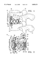
- FIG. 1 is a side elevation of a vertebral body prosthesis according to the present invention showing the invention in place in a person's spine.
- FIG. 2 is a perspective view of the vertebral body prosthesis of FIG. 1.
- FIG. 3 is a an exploded perspective view of the vertebral body prosthesis of FIG. 1.
- FIG. 4 is side elevation of the ball and socket arrangement and upper and lower plate of the vertebral body prosthesis of FIG. 1.
- FIG. 5 is a cross sectional side elevation of the apparatus of FIG. 4.
- FIG. 6 is a top plan view of the upper and lower plate assembly illustrating the preferred circular shape of these members.
- FIG. 7 is a top plan view of an alternative embodiment of the upper and lower plate assemble having an oval shape.
- FIG. 8 is a top plan view of another alternative embodiment of the upper and lower plate assembly having a kidney shape.
- a vertebral body prothesis 10 is show in place between an upper vertebra 12 and a lower vertebra 14.
- the upper vertebra 12 includes an associated upper elastic fibrous disc 16 and a lower elastic fibrous disc 18 is included in the lower vertebra 14.
- the vertebral body prothesis 10 includes an upper plate member 20 having a left-hand side group of three upwardly projecting fine needle-like spikes 22 arranged in a triangle, a right-hand side group of three upwardly projecting fine need-like spikes 24 arranged in a triangle, and a pair of circumferential upwardly projecting fine needle-like spikes 26 lying across a diameter of the upper plate member 20 in along a centerline between the groups of spikes 22, 24, all formed on the upper surface 28 of the upper plate member 20.
- a pair of opposed interchangeable upwardly projecting upper anchoring plates 30 each includes a base portion 32 that is wider and thicker than the bracket body 34, and which is fixed by welding or the like into an anchoring loop 36 fastened along the circumference of the upper plate member 20 by welding or the like.
- Each anchoring plate 30 includes a pair of vertically spaced screw apertures 38, each of which receives a bone screw 40, which is screwed into the upper disc 16.
- a downwardly projecting upper truncated cone member, or depending ball supporting member, 42 is fixed to a lower surface 44 of the upper plate member 20 at its center such that the centers of the upper plate member 20 and the upper truncated cone member are superposed.
- the widest portion of the upper truncated cone member 42 is fixed to the lower surface 44 of the upper plate member 20.
- a depending ball 46 is attached to or integrally formed with, the lower portion 47 of the upper truncated cone 42.
- the ball member 46 comprises a sphere with the top 20-35% removed, resulting in a straight line 49 plane or joiner with the cone member 42.
- the lower plate member 48 has left-hand side group of three downwardly projecting fine needle-like spikes 50 arranged in a triangle, a right-hand side group of three downwardly projecting fine need-like spikes 52 arranged in a triangle, and a pair of circumferential downwardly projecting fine needle-like spikes 54 lying across a diameter of the lower plate member 48 in along a centerline between the groups of spikes 50, 52 all formed on the lower surface 56 of the lower plate member 48.
- a pair of opposed lower anchoring plates 58 project downwardly and a fixed by welding or the like in lower anchoring loops 60 fixed in the lower plate member 48 adjacent to its circumference by welding or the like.
- the lower anchoring plates 58 are interchangeable with the upper anchoring plates 30 and discussion and reference characters pertaining to the upper anchoring plates 30 also apply to the lower anchoring plates 58.
- the lower anchoring plates 58 lie across a diameter of the lower plate member 48, i.e., are opposed, and are vertically aligned with the upper anchoring plates 30, which lie across the corresponding diameter of the upper plate member 20 in the preferred embodiment.
- the circle of the upper plate member 20 and the lower plate member 48 are considered as a twelve hour clock face with the twelve o'clock position at the farthest point away from the viewer in FIGS. 1-3, the anchoring plates 30, 58 are at 3:00 O'clock and 9:00 O'clock.
- the anchoring plates 30, 58 may be moved forward to about the 10:00 O'clock position or backward to about the 2:00 O'clock position.
- An upwardly projecting lower truncated cone member, or upstanding socket supporting member, 62 is attached to or integrally formed with, the upper surface 64 of the lower plate member 48.
- the wider end of the cone member 62 is adjacent to the lower plate member 48 and the center of the cone member 62 is located at the center of the plate member 48, so that these centers are superposed.
- a cup socket 68 having side walls 70 for receiving the ball member 46. As best seen in FIGS. 4, 5, the side walls 70 of the cup socket 68 extend upwardly beyond the diameter 72 of the ball 46, reducing the chances that the ball 46 will be forced from the cup socket 68.
- the outer surface of the cup socket 68 is basically spherical in shape, although it could be any shape, and the interior socket portion 74 is a spherical socket designed to receive and mate with the ball 46 in close tolerance.
- a lower portion 76 of the cup socket 68 is flattened where it joins the upper end 78 of the lower truncated cone member 62.
- a doughnut-shaped toroidal disc cushion 80 includes a circular outer side wall 82 perpendicular to a flat top wall 84 and to a flat bottom wall 86.
- a central aperture 90 accommodates the structures between the upper and lower plate members 20, 48.
- the disc cushion 80 is made of an elastic resilient material such as rubber, silicon, and includes reinforcing fibers 92.
- the disc cushion 80 limits tilting movement between the upper and lower plate members 20, 48 to a few degrees and cushions them, but does not bear a great deal of the forces of the spine in ordinary activities. Most of the of the forces in the spine are borne by the upper and lower plate members 20, 48, the ball 46 and cup socket 68, and the upper and lower truncated cone members 42, 62.
- fine stainless steel limiting wires 94 are attached to the perimeters of the upper and lower plate members 20, 48 in such a fashion as to result in X-shaped reinforcing structures about the entire perimeter of the upper an lower plates 20, 48. More specifically, a wire 100 and a wire 102 are connected to the upper plate at a point 104. The wire 100 runs downward toward the right to its attachment point 106 on the perimeter of the lower plate member 48, while the wire 102 runs downwardly to the left to its attachment point 108 on the lower plate member 48.
- a wire 112 runs downward to the left to the attachment point 114 on the perimeter of the lower plate member 48, while the wire 118 runs upwardly to the right from the same connection point 114 to an upper connection point 116 on the upper plate member 20.
- This pattern is repeated about the perimeter of both the upper and lower plate members 20, 48 (regardless of the plan view shape of the plate members), to provide a repeating X pattern of the limiting wires 94.
- the overall plan view of either or both upper and lower plate members 20, 46 is the circular disc 120 is a circle.
- the overall plan view of both upper and lower plate members 20, 48 can be the oval plate member 122 or the kidney-shaped plate member 124, respectively.
- the disc cushion 80 is inserted between the upper and lower plate members 20, 48 prior to assembly. Then the ball 46 is press fitted into the interior socket portion of the cup socket 68.
- the upper and lower plate members 20, 48 may be made of metal and in this case, the limiting wires 94 are welded on the plates 20, 48, the truncated cone members 42, 62, and the ball 46 and cup socket 68 may also be made of metal and are welded to the upper and lower plate members 20, 48. All the spikes are also made of metal and are welded onto the plate members 20, 48, as are the anchoring plates 30.
- each plate member 20, 48 and all spikes, truncated cones, the ball and the socket can be made in one piece from ceramic materials. In this case, the anchoring plates 30 are fixed into the bracket slots and the wires are fastened to the plates by an adhesive.
- the upper and lower truncated cones 42, 62 respectively may be any desired shape adequate to support the associated ball 46 and cup socket 68.
Abstract
An upper plate includes a depending truncated cone member that supports a ball. A lower plate supports an upstanding truncated cone member that supports a cup socket that the ball is press fitted into. The cup socket embraces the ball to a line above the middle diameter of the ball to prevent the ball from coming free of the socket in normal use. A number of wires form a repeating X pattern between the upper and lower plates about their perimeters and serve to restrain rotational motion. The upper plate includes upwardly projecting spikes and the lower plate includes downwardly projecting spikes. The upper and lower plates each include two anchoring brackets that project outwardly to lie adjacent to an upper and lower spinal disc, and that are fastened to the discs by bone screws. The spikes further anchor the vertebral body prosthesis in the adjacent spinal discs.
Description
1. Field of the Invention
The present invention is related to an apparatus for stabilizing the spine when spinal discs have deteriorated. More particularly, the present invention is related to an apparatus for replacing damaged spinal discs and vertebral bodies.
2. Description of Related Art Including Information Disclosed Under 37 C.F.R. Sections 1.9-1.99.
The spine, particularly the human spine, is composed of many vertebral bones stacked one upon the other, with an intervertebral disc between each pair of adjacent vertebral bones. The discs act as cartilaginous cushions and shock absorbers. The spinal cord runs in a bony canal formed by successive openings in these bones. The spinal nerves exit the spinal cord from small openings in the vertebral bodies and supply nerves and nerve signals to and from other body structures.
Damage to the structure of this system may arise from several causes. Accidental fractures of the bones leads to disruption and collapse of spinal discs and hence pinching of important nerves in the spinal cord. Collapsed, herniated or bulging discs can also pinch the nerves in the spinal cord or nerves exiting the spinal cord. Post operative scarring often lead to disruption of the spinal cord and associated structures.
Surgery is often required to reconstruct the vertebral bodies, remove the herniated discs, and to implant certain hardware to stabilize the spine. Such hardware typically comprises rods, screws, and plates. A scaffolding is formed to lift and hold the bony structures formed by the vertebral bones. Unfortunately, many of these hardware structures fail when they lose bony purchase, pierce unwanted structures, and so forth. Further, many of these structures unnecessarily limit the patient's range of spinal motion, particularly rotational movement. Many such structures, for example, the spine discs disclosed in U.S. Pat. Nos. 5,676,702, 5,645,599 and 5,702,450, tend to deteriorate over time and so cannot be considered permanent.
Therefore, a need exists for a vertebral body prosthesis that does not lose bony purchase over time, that does not unnecessarily limit the patient's range of spinal motion, particularly rotational movement, and that is stable over a long period of time.
Accordingly, it is a primary object of the present invention to provide a vertebral body prosthesis that does not lose bony purchase over time.
It is another object of the present invention to provide a vertebral body prosthesis that does not unnecessarily limit the patient's range of spinal motion, particularly rotational movement.
It is another object of the present invention to provide a vertebral body prosthesis that is stable over a long period of time.
These and other objects of the present invention are achieved by providing an upper plate having a depending truncated cone member that supports a ball. A lower plate supports an upstanding truncated cone member that supports a cup socket that the ball is press fitted into. The cup socket embraces the ball to a line above the middle diameter of the ball to prevent the ball from coming free of the socket in normal use. A number of wires form a repeating X pattern between the upper and lower plates about the perimeter of the plates and serve to restrain rotational motion. The upper plate includes upwardly projecting spikes and the lower plate includes downwardly projecting spikes. The upper and lower plates each include two anchoring brackets that project outwardly to lie adjacent to an upper and lower vertebral bodies and that are fastened to the vertebral bodies by bone screws. The spikes further anchor the vertebral body prosthesis in the adjacent spinal discs or the vertebral body surfaces after removing the damaged disc.
Other objects and advantages of the present invention will become apparent from the following description taken in connection with the accompanying drawings, it is set forth by way of illustration and example, the preferred embodiment of the present invention and the best mode currently known to the inventor for carrying out his invention.
FIG. 1 is a side elevation of a vertebral body prosthesis according to the present invention showing the invention in place in a person's spine.
FIG. 2 is a perspective view of the vertebral body prosthesis of FIG. 1.
FIG. 3 is a an exploded perspective view of the vertebral body prosthesis of FIG. 1.
FIG. 4 is side elevation of the ball and socket arrangement and upper and lower plate of the vertebral body prosthesis of FIG. 1.
FIG. 5 is a cross sectional side elevation of the apparatus of FIG. 4.
FIG. 6 is a top plan view of the upper and lower plate assembly illustrating the preferred circular shape of these members.
FIG. 7 is a top plan view of an alternative embodiment of the upper and lower plate assemble having an oval shape.
FIG. 8 is a top plan view of another alternative embodiment of the upper and lower plate assembly having a kidney shape.
Referring to FIG. 1, a vertebral body prothesis 10 according to the present invention is show in place between an upper vertebra 12 and a lower vertebra 14. The upper vertebra 12 includes an associated upper elastic fibrous disc 16 and a lower elastic fibrous disc 18 is included in the lower vertebra 14.
Referring to FIGS. 1-3, the vertebral body prothesis 10, includes an upper plate member 20 having a left-hand side group of three upwardly projecting fine needle-like spikes 22 arranged in a triangle, a right-hand side group of three upwardly projecting fine need-like spikes 24 arranged in a triangle, and a pair of circumferential upwardly projecting fine needle-like spikes 26 lying across a diameter of the upper plate member 20 in along a centerline between the groups of spikes 22, 24, all formed on the upper surface 28 of the upper plate member 20. A pair of opposed interchangeable upwardly projecting upper anchoring plates 30 each includes a base portion 32 that is wider and thicker than the bracket body 34, and which is fixed by welding or the like into an anchoring loop 36 fastened along the circumference of the upper plate member 20 by welding or the like. Each anchoring plate 30 includes a pair of vertically spaced screw apertures 38, each of which receives a bone screw 40, which is screwed into the upper disc 16. A downwardly projecting upper truncated cone member, or depending ball supporting member, 42 is fixed to a lower surface 44 of the upper plate member 20 at its center such that the centers of the upper plate member 20 and the upper truncated cone member are superposed. The widest portion of the upper truncated cone member 42 is fixed to the lower surface 44 of the upper plate member 20. A depending ball 46 is attached to or integrally formed with, the lower portion 47 of the upper truncated cone 42. The ball member 46 comprises a sphere with the top 20-35% removed, resulting in a straight line 49 plane or joiner with the cone member 42.
Still referring to FIGS. 1-3, the lower plate member 48 has left-hand side group of three downwardly projecting fine needle-like spikes 50 arranged in a triangle, a right-hand side group of three downwardly projecting fine need-like spikes 52 arranged in a triangle, and a pair of circumferential downwardly projecting fine needle-like spikes 54 lying across a diameter of the lower plate member 48 in along a centerline between the groups of spikes 50, 52 all formed on the lower surface 56 of the lower plate member 48. A pair of opposed lower anchoring plates 58 project downwardly and a fixed by welding or the like in lower anchoring loops 60 fixed in the lower plate member 48 adjacent to its circumference by welding or the like. In construction, installation and use, the lower anchoring plates 58 are interchangeable with the upper anchoring plates 30 and discussion and reference characters pertaining to the upper anchoring plates 30 also apply to the lower anchoring plates 58. The lower anchoring plates 58 lie across a diameter of the lower plate member 48, i.e., are opposed, and are vertically aligned with the upper anchoring plates 30, which lie across the corresponding diameter of the upper plate member 20 in the preferred embodiment. This results in an upper anchoring plate 30 on the right-hand side of the vertebral body prosthesis 10 and another on the left-hand side of the vertebral body prosthesis 10 and in both cases the upper anchoring plates 30 are in the middle of the sides so as to maximize their purchase on the vertebral bodies 12, 14 and the lower anchoring plates 58 are directly below the upper anchoring plates 30. If the circle of the upper plate member 20 and the lower plate member 48 are considered as a twelve hour clock face with the twelve o'clock position at the farthest point away from the viewer in FIGS. 1-3, the anchoring plates 30, 58 are at 3:00 O'clock and 9:00 O'clock. In an alternative embodiment, the anchoring plates 30, 58 may be moved forward to about the 10:00 O'clock position or backward to about the 2:00 O'clock position.
An upwardly projecting lower truncated cone member, or upstanding socket supporting member, 62 is attached to or integrally formed with, the upper surface 64 of the lower plate member 48. The wider end of the cone member 62 is adjacent to the lower plate member 48 and the center of the cone member 62 is located at the center of the plate member 48, so that these centers are superposed. At the upper, or narrow, end 66 of the lower truncated cone member 62 is a cup socket 68 having side walls 70 for receiving the ball member 46. As best seen in FIGS. 4, 5, the side walls 70 of the cup socket 68 extend upwardly beyond the diameter 72 of the ball 46, reducing the chances that the ball 46 will be forced from the cup socket 68. The outer surface of the cup socket 68 is basically spherical in shape, although it could be any shape, and the interior socket portion 74 is a spherical socket designed to receive and mate with the ball 46 in close tolerance. A lower portion 76 of the cup socket 68 is flattened where it joins the upper end 78 of the lower truncated cone member 62.
The ball 46 and cup socket 68 arrangement fit and lock into each other and prevent radial movement, but facilitate axial rotational movement The upper and lower plate members 20, 48 can rotate about a vertical axis, and tilt at basically any angle through about 45-75% relative to the vertical throughout the full rotation, but cannot be compressed. A doughnut-shaped toroidal disc cushion 80 includes a circular outer side wall 82 perpendicular to a flat top wall 84 and to a flat bottom wall 86. A central aperture 90 accommodates the structures between the upper and lower plate members 20, 48. The disc cushion 80 is made of an elastic resilient material such as rubber, silicon, and includes reinforcing fibers 92. The disc cushion 80 limits tilting movement between the upper and lower plate members 20, 48 to a few degrees and cushions them, but does not bear a great deal of the forces of the spine in ordinary activities. Most of the of the forces in the spine are borne by the upper and lower plate members 20, 48, the ball 46 and cup socket 68, and the upper and lower truncated cone members 42, 62.
Referring to FIGS. 1, 2, to limit excessive relative rotation of the upper and lower plate members 20, 48, which are superposed when assembled, relative to a vertical axis through the center of the upper and lower plate member 20, 48, fine stainless steel limiting wires 94 are attached to the perimeters of the upper and lower plate members 20, 48 in such a fashion as to result in X-shaped reinforcing structures about the entire perimeter of the upper an lower plates 20, 48. More specifically, a wire 100 and a wire 102 are connected to the upper plate at a point 104. The wire 100 runs downward toward the right to its attachment point 106 on the perimeter of the lower plate member 48, while the wire 102 runs downwardly to the left to its attachment point 108 on the lower plate member 48. From an attachment point 110 on the upper plate member 20, a wire 112 runs downward to the left to the attachment point 114 on the perimeter of the lower plate member 48, while the wire 118 runs upwardly to the right from the same connection point 114 to an upper connection point 116 on the upper plate member 20. This pattern is repeated about the perimeter of both the upper and lower plate members 20, 48 (regardless of the plan view shape of the plate members), to provide a repeating X pattern of the limiting wires 94.
Referring now to FIG. 6 the overall plan view of either or both upper and lower plate members 20, 46 is the circular disc 120 is a circle. As shown in FIGS. 7, 8, in alternative embodiments the overall plan view of both upper and lower plate members 20, 48 can be the oval plate member 122 or the kidney-shaped plate member 124, respectively.
The disc cushion 80 is inserted between the upper and lower plate members 20, 48 prior to assembly. Then the ball 46 is press fitted into the interior socket portion of the cup socket 68. The upper and lower plate members 20, 48, may be made of metal and in this case, the limiting wires 94 are welded on the plates 20, 48, the truncated cone members 42, 62, and the ball 46 and cup socket 68 may also be made of metal and are welded to the upper and lower plate members 20, 48. All the spikes are also made of metal and are welded onto the plate members 20, 48, as are the anchoring plates 30. Alternatively, each plate member 20, 48 and all spikes, truncated cones, the ball and the socket, can be made in one piece from ceramic materials. In this case, the anchoring plates 30 are fixed into the bracket slots and the wires are fastened to the plates by an adhesive. The upper and lower truncated cones 42, 62 respectively may be any desired shape adequate to support the associated ball 46 and cup socket 68.
While the present invention has been described in accordance with the preferred embodiments thereof, the description is for illustration only and should not be construed as limiting the scope of the invention. Various changes and modifications may be made by those skilled in the art without departing from the spirit and scope of the invention as defined by the following claims.
Claims (12)
1. A vertebral body prosthesis comprising:
a. an upper plate having a depending ball supporting member comprising a truncated cone member projecting downwardly from said plate and having a narrower end lower than a wider end, with said lower end terminating in a depending ball portion;
b. a lower plate having an upstanding hemispherical socket supporting member having an upper end connected to a hemispherical socket, with said ball seated in said socket; and
c. a resilient toroidal disc interposed between said upper plate and said lower plate.
2. A vertebral body prosthesis in accordance with claim 1 further comprising a plurality of upwardly projecting spikes on an upper surface of said upper plate and a plurality of downwardly projecting spikes on a lower surface of said lower plate.
3. A vertebral body prosthesis in accordance with claim 1 further comprising a plurality of upwardly projecting anchoring brackets fastened to a perimeter of said upper plate, wherein each said bracket comprises an elongated bracket member having two vertically aligned apertures for receiving anchoring fasteners and said bracket member further comprises a thickened lower section for securing said bracket member in an anchoring loop fastened to said upper plate.
4. A vertebral body prosthesis in accordance with claim 1 further comprising a plurality of downwardly projecting anchoring brackets fastened to a perimeter of said lower plate, wherein each said bracket comprises an elongated bracket member having two vertically aligned apertures for receiving anchoring fasteners and said bracket member further comprises a thickened upper section for securing said bracket member in an anchoring loop fastened to said lower plate.
5. A vertebral body prosthesis in accordance with claim 1 wherein said socket comprises an upper edge and said upper edge extends upwardly above the diameter of said depending ball.
6. A vertebral body prosthesis in accordance with claim 1, further comprising a plurality of wires fastened to said upper plate and to said lower plate, wherein said wires form a repeating X pattern about the perimeter of said upper plate and said lower plate, wherein each X comprises an two upper arms, each said arm having an upper end, and two lower arms, each said arm having a lower end, and each upper end of each said upper arm is connected to an upper arm of an adjoining X and each said lower end of each said lower arm is connected to a lower arm of an adjoining X and said upper and lower ends are fastened to an edge of said upper plate or said lower plate.
7. A vertebral body prosthesis in accordance with claim 1 wherein said resilient toroidal disc comprises a layer of reinforcing fibers.
8. A vertebral body prosthesis in accordance with claim 1 further comprising a plurality of anchoring loops connected to said upper plate and a plurality of anchoring loops connected to said lower plate, wherein each said anchoring loop comprises a wire loop fastened to one said upper or said lower plate for receiving an anchoring bracket, which is retained in said anchoring loop by a thickened end portion of each said anchoring bracket.
9. A vertebral body prosthesis comprising:
a. an upper plate having a depending ball supporting member comprising a truncated cone member projecting downwardly from said plate and having a narrower end lower than a wider end, with said lower end terminating in a depending spherical ball portion;
b. a lower plate having an upstanding hemispherical socket supporting member comprising a truncated cone having a narrower end and a wider end, with said wider end connected to said lower plate, said socket supporting member having an upper end connected to a hemispherical socket, with said ball seated in said socket; and
c. a toroidal disc interposed between said upper plate and said lower plate; and
d. a plurality of wires arrayed in a repeating X pattern, each said wire having one end connected to said upper plate and a second end connected to said lower plate.
10. A vertebral body prosthesis in accordance with claim 9 further comprising a plurality of upwardly projecting spikes connected to an upper surface of said upper plate and a plurality of downwardly projecting spikes connected to a lower surface of said lower plate.
11. A vertebral body prosthesis in accordance with claim 9 further comprising a repeating X pattern formed by said wires, wherein each X comprises two upper arms, each said arm having an upper end, and two lower arms, each said arm having a lower end, and each upper end of each said upper arm is connected to an upper arm of an adjoining X and each said lower end of each said lower arm is connected to a lower arm of an adjoining X.
12. A vertebral body prosthesis in accordance with claim 9 wherein said toroidal disc comprises a doughnut-shaped toroidal disc cushion further comprising an upper elastic resilient member and a lower elastic resilient member and a plurality of reinforcing fibers between said upper and lower elastic resilient members.
Priority Applications (2)
| Application Number | Priority Date | Filing Date | Title |
|---|---|---|---|
| US09/124,495 US6063121A (en) | 1998-07-29 | 1998-07-29 | Vertebral body prosthesis |
| CA002300613A CA2300613C (en) | 1998-07-29 | 2000-03-14 | Vertebral body prosthesis |
Applications Claiming Priority (2)
| Application Number | Priority Date | Filing Date | Title |
|---|---|---|---|
| US09/124,495 US6063121A (en) | 1998-07-29 | 1998-07-29 | Vertebral body prosthesis |
| CA002300613A CA2300613C (en) | 1998-07-29 | 2000-03-14 | Vertebral body prosthesis |
Publications (1)
| Publication Number | Publication Date |
|---|---|
| US6063121A true US6063121A (en) | 2000-05-16 |
Family
ID=25681615
Family Applications (1)
| Application Number | Title | Priority Date | Filing Date |
|---|---|---|---|
| US09/124,495 Expired - Lifetime US6063121A (en) | 1998-07-29 | 1998-07-29 | Vertebral body prosthesis |
Country Status (2)
| Country | Link |
|---|---|
| US (1) | US6063121A (en) |
| CA (1) | CA2300613C (en) |
Cited By (358)
| Publication number | Priority date | Publication date | Assignee | Title |
|---|---|---|---|---|
| US6419703B1 (en) | 2001-03-01 | 2002-07-16 | T. Wade Fallin | Prosthesis for the replacement of a posterior element of a vertebra |
| US20020128715A1 (en) * | 2000-08-08 | 2002-09-12 | Vincent Bryan | Implantable joint prosthesis |
| US6468310B1 (en) | 2001-07-16 | 2002-10-22 | Third Millennium Engineering, Llc | Intervertebral spacer device having a wave washer force restoring element |
| US20030004572A1 (en) * | 2001-03-02 | 2003-01-02 | Goble E. Marlowe | Method and apparatus for spine joint replacement |
| WO2003007779A2 (en) * | 2001-07-16 | 2003-01-30 | Third Millenium Engineering Llc | Artificial intervertebral disc having a deformable wire mesh vertebral body contact element |
| US20030028250A1 (en) * | 1999-10-22 | 2003-02-06 | Archus Orthopedics, Inc. | Prostheses, systems and methods for replacement of natural facet joints with artifical facet joint surfaces |
| US20030040802A1 (en) * | 2001-07-16 | 2003-02-27 | Errico Joseph P. | Artificial intervertebral disc having limited rotation using a captured ball and socket joint with a solid ball and compression locking post |
| US6527806B2 (en) | 2001-07-16 | 2003-03-04 | Third Millennium Engineering, Llc | Intervertebral spacer device having a spiral wave washer force restoring element |
| US20030055427A1 (en) * | 1999-12-01 | 2003-03-20 | Henry Graf | Intervertebral stabilising device |
| US20030069643A1 (en) * | 2001-07-16 | 2003-04-10 | Ralph James D. | Tension bearing artificial disc providing a centroid of motion centrally located within an intervertebral space |
| WO2003032801A2 (en) * | 2001-10-18 | 2003-04-24 | Third Millennium Engineering Llc | Artificial intervertebral disc having a spider spring force restoring element |
| WO2003032802A2 (en) * | 2001-10-18 | 2003-04-24 | Third Millennium Engineering Llc | Intervertebral spacer device having an arched spring element |
| US6562045B2 (en) | 2001-02-13 | 2003-05-13 | Sdgi Holdings, Inc. | Machining apparatus |
| US6565605B2 (en) | 2000-12-13 | 2003-05-20 | Medicinelodge, Inc. | Multiple facet joint replacement |
| US6572653B1 (en) * | 2001-12-07 | 2003-06-03 | Rush E. Simonson | Vertebral implant adapted for posterior insertion |
| US6579319B2 (en) | 2000-11-29 | 2003-06-17 | Medicinelodge, Inc. | Facet joint replacement |
| US20030135277A1 (en) * | 2001-11-26 | 2003-07-17 | Sdgi Holdings, Inc. | Implantable joint prosthesis and associated instrumentation |
| US6610092B2 (en) | 2001-10-18 | 2003-08-26 | Spinefore, Inc. | Intervertebral spacer device having a slotted partial circular domed arch strip spring |
| US20030176926A1 (en) * | 2000-11-13 | 2003-09-18 | Boehm Frank H. | Device and method for lumbar interbody fusion |
| US20030174929A1 (en) * | 2002-03-15 | 2003-09-18 | Rodgers Murray Steven | Self-shadowing MEM structures |
| US6626943B2 (en) * | 2001-08-24 | 2003-09-30 | Sulzer Orthopedics Ltd. | Artificial intervertebral disc |
| US20030199982A1 (en) * | 1998-09-04 | 2003-10-23 | Sdgi Holdings, Inc. | Peanut spectacle multi discoid thoraco-lumbar disc prosthesis |
| US20030199738A1 (en) * | 2000-08-08 | 2003-10-23 | Sdgi Holdings,Inc. | Clamping apparatus and methods |
| US20030204271A1 (en) * | 2002-04-24 | 2003-10-30 | Ferree Bret A. | Check reins for artificial disc replacements |
| US20030204260A1 (en) * | 2002-04-30 | 2003-10-30 | Ferree Bret A. | Methods and apparatus for preventing the migration of intradiscal devices |
| US6645248B2 (en) * | 2001-08-24 | 2003-11-11 | Sulzer Orthopedics Ltd. | Artificial intervertebral disc |
| US6660038B2 (en) * | 2000-03-22 | 2003-12-09 | Synthes (Usa) | Skeletal reconstruction cages |
| US20030229358A1 (en) * | 2001-07-16 | 2003-12-11 | Errico Joseph P. | Wedge plate inserter/impactor and related methods for use in implanting an artificial intervertebral disc |
| US6669730B2 (en) | 2001-02-15 | 2003-12-30 | Spinecore, Inc. | Intervertebral spacer device utilizing a spirally slotted belleville washer having radially extending grooves |
| US20040002762A1 (en) * | 2002-06-27 | 2004-01-01 | Hawkins John Riley | Prosthetic intervertebral motion disc having dampening |
| EP1374807A1 (en) * | 2002-06-18 | 2004-01-02 | DePuy AcroMed, Inc. | Intervertebral disc |
| US6682562B2 (en) * | 2000-03-10 | 2004-01-27 | Eurosurgical Sa | Intervertebral disc prosthesis |
| US20040024462A1 (en) * | 2002-04-12 | 2004-02-05 | Ferree Bret A. | Spacerless artificial disc replacements |
| US20040024460A1 (en) * | 2002-05-10 | 2004-02-05 | Ferree Bret A. | Prosthetic components with partially contained compressible resilient members |
| US20040024461A1 (en) * | 2002-05-10 | 2004-02-05 | Ferree Bret A. | Spring and spherical joint artificial disc replacements |
| US20040044410A1 (en) * | 2002-05-10 | 2004-03-04 | Ferree Bret A. | Prosthetic components with contained compressible resilient members |
| US20040054411A1 (en) * | 2000-08-08 | 2004-03-18 | Sdgi Holdings, Inc. | Wear-resistant endoprosthetic devices |
| WO2004028415A1 (en) * | 2002-09-26 | 2004-04-08 | Spinecore, Inc. | Artificial intervertebral disc having a captured ball and socket joint |
| US20040073312A1 (en) * | 2002-01-09 | 2004-04-15 | Lukas Eisermann | Intervertebral prosthetic joint |
| US20040073311A1 (en) * | 2002-04-23 | 2004-04-15 | Ferree Bret A. | Two-component artificial disc replacements |
| US6723127B2 (en) | 2001-07-16 | 2004-04-20 | Spine Core, Inc. | Artificial intervertebral disc having a wave washer force restoring element |
| US20040083000A1 (en) * | 2002-03-12 | 2004-04-29 | Waldemar Link Gmbh & Co. | Cervical intervertebral prosthesis |
| US20040092943A1 (en) * | 2002-01-14 | 2004-05-13 | Buttermann Glenn Robin | Apparatus and method for performing spinal surgery |
| US20040098131A1 (en) * | 1996-07-22 | 2004-05-20 | Sdgi Holdings, Inc. | Human spinal disc prosthesis |
| US6740117B2 (en) | 2001-02-15 | 2004-05-25 | Spinecore, Inc. | Intervertebral spacer device having a radially thinning slotted belleville spring |
| US20040106998A1 (en) * | 2002-10-04 | 2004-06-03 | Ferree Bret A. | Multiaxial artificial disc replacements |
| US20040111155A1 (en) * | 2002-05-10 | 2004-06-10 | Ferree Bret A. | Artificial disc replacement (ADR) using elastic tether member |
| US20040116927A1 (en) * | 2000-12-01 | 2004-06-17 | Henry Graf | Intervertebral stabilizing device |
| US20040122517A1 (en) * | 2002-12-10 | 2004-06-24 | Axiomed Spine Corporation | Artificial disc |
| WO2004052247A1 (en) * | 2002-12-10 | 2004-06-24 | Sdgi Holdings, Inc. | Implant system and method for intervertebral disc augmentation |
| US6764515B2 (en) | 2001-02-15 | 2004-07-20 | Spinecore, Inc. | Intervertebral spacer device utilizing a spirally slotted belleville washer and a rotational mounting |
| US20040158254A1 (en) * | 2003-02-12 | 2004-08-12 | Sdgi Holdings, Inc. | Instrument and method for milling a path into bone |
| US20040167534A1 (en) * | 2001-07-16 | 2004-08-26 | Errico Joseph P. | Instrumentation for inserting and impacting an artificial intervertebral disc in an intervertebral space |
| US20040172136A1 (en) * | 2001-10-01 | 2004-09-02 | Ralph James D. | Intervertebral spacer device utilizing a belleville washer having radially extending grooves |
| US20040176773A1 (en) * | 2003-03-06 | 2004-09-09 | Rafail Zubok | Instrumentation and methods for use in implanting a cervical disc replacement device |
| US20040193272A1 (en) * | 2003-03-06 | 2004-09-30 | Rafail Zubok | Instrumentation and methods for use in implanting a cervical disc replacement device |
| US20040187981A1 (en) * | 2002-04-05 | 2004-09-30 | Masaharu Ueda | Pealite base rail excellent in wear resistance and ductility and method for production thereof |
| US20040199253A1 (en) * | 2003-04-07 | 2004-10-07 | Cervitech, Inc. | Cervical intervertebral disk prosthesis |
| US20040199254A1 (en) * | 2001-07-13 | 2004-10-07 | Christian Louis | Vertebral cage device with modular fixation |
| WO2004087021A1 (en) * | 2003-04-03 | 2004-10-14 | Enztec Limited | Load bearing intervertebral disk |
| US20040204761A1 (en) * | 2001-10-01 | 2004-10-14 | Ralph James D. | Intervertebral spacer device utilizing a belleville washer having radially spaced concentric grooves |
| US20040210310A1 (en) * | 2002-12-10 | 2004-10-21 | Trieu Hai H. | Implant system and method for intervertebral disc augmentation |
| US20040220671A1 (en) * | 2001-10-01 | 2004-11-04 | Ralph James D | Intervertebral spacer device utilizing a spirally slotted belleville washer and a rotational mounting |
| US20040225364A1 (en) * | 2003-05-06 | 2004-11-11 | Marc Richelsoph | Artificial intervertebral disc |
| US20040225363A1 (en) * | 2003-05-06 | 2004-11-11 | Marc Richelsoph | Artificial intervertebral disc |
| US20040230304A1 (en) * | 2003-05-14 | 2004-11-18 | Archus Orthopedics Inc. | Prostheses, tools and methods for replacement of natural facet joints with artifical facet joint surfaces |
| US20040243240A1 (en) * | 2001-05-04 | 2004-12-02 | Jacques Beaurain | Intervertebral disc prosthesis and fitting tools |
| US20040249465A1 (en) * | 2003-06-06 | 2004-12-09 | Ferree Bret A. | Methods and apparatus for total disc replacements with oblique keels |
| US20040254644A1 (en) * | 2002-10-21 | 2004-12-16 | Taylor Brett Allison | Intervertebral disk prosthesis |
| US20040267369A1 (en) * | 2002-04-25 | 2004-12-30 | Matthew Lyons | Artificial intervertebral disc |
| US20040267367A1 (en) * | 2003-06-30 | 2004-12-30 | Depuy Acromed, Inc | Intervertebral implant with conformable endplate |
| US20050010291A1 (en) * | 2003-07-08 | 2005-01-13 | Archus Orthopedics Inc. | Prostheses, tools and methods for replacement of natural facet joints with artificial facet joint surfaces |
| US20050010215A1 (en) * | 2001-10-18 | 2005-01-13 | Joel Delecrin | Plate for osteosynthesis device and preassembling method |
| US20050015152A1 (en) * | 2003-07-15 | 2005-01-20 | Spinal Generations | Spinal disc prosthesis system |
| US20050021042A1 (en) * | 2003-07-21 | 2005-01-27 | Theirry Marnay | Instruments and method for inserting an intervertebral implant |
| DE10330698A1 (en) * | 2003-07-08 | 2005-02-03 | Aesculap Ag & Co. Kg | Intervertebral implant |
| US20050027361A1 (en) * | 1999-10-22 | 2005-02-03 | Reiley Mark A. | Facet arthroplasty devices and methods |
| US20050043800A1 (en) * | 2003-07-31 | 2005-02-24 | Paul David C. | Prosthetic spinal disc replacement |
| US20050043803A1 (en) * | 2003-08-22 | 2005-02-24 | Robert Schultz | Intervertebral implant |
| US6863688B2 (en) | 2001-02-15 | 2005-03-08 | Spinecore, Inc. | Intervertebral spacer device utilizing a spirally slotted belleville washer having radially spaced concentric grooves |
| US20050055098A1 (en) * | 2003-09-10 | 2005-03-10 | Sdgi Holdings, Inc. | Artificial spinal discs and associated implantation and revision methods |
| US20050060036A1 (en) * | 2003-05-21 | 2005-03-17 | Robert Schultz | Spinal column implant |
| US20050060034A1 (en) * | 2003-09-15 | 2005-03-17 | Sdgi Holdings, Inc. | Revisable prosthetic device |
| US20050059976A1 (en) * | 2000-08-08 | 2005-03-17 | Sdgi Holdings, Inc. | Method and apparatus for stereotactic implantation |
| US20050071007A1 (en) * | 2003-09-30 | 2005-03-31 | Malek Michel H. | Intervertebral disc prosthesis |
| US20050075644A1 (en) * | 2003-10-02 | 2005-04-07 | Dipoto Gene | Methods and apparatuses for minimally invasive replacement of intervertebral discs |
| US20050080487A1 (en) * | 2003-10-08 | 2005-04-14 | Robert Schultz | Intervertebral implant |
| US20050080486A1 (en) * | 2000-11-29 | 2005-04-14 | Fallin T. Wade | Facet joint replacement |
| US20050085909A1 (en) * | 2003-10-15 | 2005-04-21 | Sdgi Holding, Inc. | Semi-constrained and mobile-bearing disc prosthesis |
| US6887274B2 (en) | 2001-02-15 | 2005-05-03 | Spinecore, Inc. | Intervertebral spacer device utilizing a belleville washer having radially spaced concentric grooves |
| US20050102028A1 (en) * | 2003-11-07 | 2005-05-12 | Uri Arnin | Spinal prostheses |
| US20050102029A1 (en) * | 2003-10-28 | 2005-05-12 | Nu Vasive, Inc. | Total disc replacement system and related methods |
| US20050102027A1 (en) * | 2003-11-12 | 2005-05-12 | Ferree Bret A. | Shims, particularly for laterally placed artificial disc replacements (ADRS) |
| US20050113924A1 (en) * | 2003-08-07 | 2005-05-26 | Dynamic Spine, Inc. | Apparatus and method for performing spinal surgery |
| WO2005046533A1 (en) * | 2003-10-17 | 2005-05-26 | Cervitech, Inc. | Set of cervical intervertebral prostheses |
| US20050113927A1 (en) * | 2003-11-25 | 2005-05-26 | Malek Michel H. | Spinal stabilization systems |
| US20050125064A1 (en) * | 2001-02-15 | 2005-06-09 | Spinecore, Inc. | Intervertebral spacer device |
| US20050143749A1 (en) * | 2003-12-31 | 2005-06-30 | Depuy Spine, Inc. | Inserter instrument and implant clip |
| US20050143824A1 (en) * | 2003-05-06 | 2005-06-30 | Marc Richelsoph | Artificial intervertebral disc |
| US20050149189A1 (en) * | 2004-01-07 | 2005-07-07 | Mokhtar Mourad B. | Intervertebral disk prosthesis |
| US20050149192A1 (en) * | 2003-11-20 | 2005-07-07 | St. Francis Medical Technologies, Inc. | Intervertebral body fusion cage with keels and implantation method |
| US20050149193A1 (en) * | 2003-11-20 | 2005-07-07 | St. Francis Medical Technology, Inc. | Intervertebral body fusion cage with keels and implantation methods |
| US20050165484A1 (en) * | 2004-01-22 | 2005-07-28 | Ferree Bret A. | Artificial disc replacement (ADR) fixation methods and apparatus |
| US20050165486A1 (en) * | 2004-01-27 | 2005-07-28 | Sdgi Holdings, Inc. | Prosthetic device and method |
| US20050187627A1 (en) * | 2001-07-16 | 2005-08-25 | Spinecore, Inc. | Intervertebral spacer having a flexible wire mesh vertebral body contact element |
| US20050187632A1 (en) * | 2004-02-20 | 2005-08-25 | Rafail Zubok | Artificial intervertebral disc having a bored semispherical bearing with a compression locking post and retaining caps |
| US20050187631A1 (en) * | 2004-01-27 | 2005-08-25 | Sdgi Holdings, Inc. | Prosthetic device |
| US6936071B1 (en) | 1999-07-02 | 2005-08-30 | Spine Solutions, Inc. | Intervertebral implant |
| US20050192674A1 (en) * | 1999-10-08 | 2005-09-01 | Ferree Bret A. | Prosthetic joints with contained compressible resilient members |
| US20050197703A1 (en) * | 2004-03-03 | 2005-09-08 | Diaz Robert L. | Spinal implant |
| US20050197702A1 (en) * | 2002-08-15 | 2005-09-08 | Coppes Justin K. | Intervertebral disc implant |
| US20050203625A1 (en) * | 2000-11-13 | 2005-09-15 | Boehm Frank H.Jr. | Device and method for lumbar interbody fusion |
| US20050203626A1 (en) * | 2004-03-15 | 2005-09-15 | Sdgi Holdings, Inc. | System and method for stabilizing a prosthetic device |
| US20050209693A1 (en) * | 2004-03-02 | 2005-09-22 | Janzen Lo | Spinal implants |
| US20050216081A1 (en) * | 2004-03-29 | 2005-09-29 | Taylor Brett A | Arthroplasty spinal prosthesis and insertion device |
| US20050228500A1 (en) * | 2003-08-01 | 2005-10-13 | Spinal Kinetics, Inc. | Prosthetic intervertebral disc and methods for using same |
| US20050228381A1 (en) * | 2004-04-09 | 2005-10-13 | Kirschman David L | Disk augmentation system and method |
| US20050228497A1 (en) * | 2002-04-23 | 2005-10-13 | Ferree Bret A | Artificial disc replacements with natural kinematics |
| US20050228501A1 (en) * | 2003-09-15 | 2005-10-13 | Sdgi Holdings, Inc. | Spinal implant system |
| US20050235508A1 (en) * | 2004-04-22 | 2005-10-27 | Archus Orthopedics, Inc. | Facet joint prosthesis measurement and implant tools |
| US20050240265A1 (en) * | 2004-04-22 | 2005-10-27 | Kuiper Mark K | Crossbar spinal prosthesis having a modular design and related implantation methods |
| US20050246022A1 (en) * | 2004-02-20 | 2005-11-03 | Rafail Zubok | Artificial intervertebral disc having a universal joint |
| US20050251170A1 (en) * | 2004-05-07 | 2005-11-10 | Ethicon Endo-Surgery, Inc. | Instrument for effecting anastomosis of respective tissues defining two body lumens |
| US20050251261A1 (en) * | 2004-05-05 | 2005-11-10 | Sdgi Holdings, Inc. | Artificial intervertebral disc for lateral insertion |
| US20050251260A1 (en) * | 2002-08-15 | 2005-11-10 | David Gerber | Controlled artificial intervertebral disc implant |
| US20050261772A1 (en) * | 2004-05-18 | 2005-11-24 | Zimmer Gmbh | Intervertebral disk implant |
| WO2005112835A2 (en) * | 2002-12-31 | 2005-12-01 | Depuy Spine, Inc. | Functional spinal unit prosthetic |
| US20050273111A1 (en) * | 1999-10-08 | 2005-12-08 | Ferree Bret A | Methods and apparatus for intervertebral disc removal and endplate preparation |
| US6981989B1 (en) * | 2003-04-22 | 2006-01-03 | X-Pantu-Flex Drd Limited Liability Company | Rotatable and reversibly expandable spinal hydraulic prosthetic device |
| US20060004453A1 (en) * | 2004-06-30 | 2006-01-05 | Depuy Spine, Inc. | Ceramic disc prosthesis |
| US20060009849A1 (en) * | 1999-10-22 | 2006-01-12 | Reiley Mark A | Facet arthroplasty devices and methods |
| US20060009541A1 (en) * | 2004-07-09 | 2006-01-12 | Yih-Fang Chen | Saturant for friction material containing friction modifying layer |
| US20060015183A1 (en) * | 2004-07-09 | 2006-01-19 | Pioneer Laboratories, Inc. | Skeletal reconstruction device |
| US20060020341A1 (en) * | 2004-06-16 | 2006-01-26 | Susanne Schneid | Intervertebral implant |
| US20060020342A1 (en) * | 2004-07-21 | 2006-01-26 | Ferree Bret A | Facet-preserving artificial disc replacements |
| US20060025778A1 (en) * | 2004-07-21 | 2006-02-02 | Ferree Bret A | Methods and apparatus for artificial disc replacement (ADR) insertion and other surgical procedures |
| US20060041313A1 (en) * | 2004-08-19 | 2006-02-23 | Sdgi Holdings, Inc. | Intervertebral disc system |
| US20060052870A1 (en) * | 2004-09-09 | 2006-03-09 | Ferree Bret A | Methods and apparatus to prevent movement through artificial disc replacements |
| US20060085076A1 (en) * | 2004-10-15 | 2006-04-20 | Manoj Krishna | Posterior spinal arthroplasty-development of a new posteriorly inserted artificial disc and an artificial facet joint |
| US20060095132A1 (en) * | 2004-10-29 | 2006-05-04 | X-Spine Systems, Inc. | Prosthetic implant and method |
| US7048764B2 (en) * | 2003-01-07 | 2006-05-23 | Ferree Bret A | Artificial disc replacements with articulating components |
| US20060142860A1 (en) * | 2003-04-04 | 2006-06-29 | Theken Disc, Llc | Artificial disc prosthesis |
| US20060149272A1 (en) * | 2004-12-13 | 2006-07-06 | St. Francis Medical Technologies, Inc. | Inter-cervical facet implant and method |
| US20060149239A1 (en) * | 2004-12-13 | 2006-07-06 | St. Francis Medical Technologies, Inc. | Inter-cervical facet implant with locking screw and method |
| US20060149378A1 (en) * | 2004-11-24 | 2006-07-06 | Brad Chase | Articulating spinal disc prosthetic |
| US20060155297A1 (en) * | 2003-10-23 | 2006-07-13 | Ainsworth Stephen D | Driver assembly for simultaneous axial delivery of spinal implants |
| US20060155377A1 (en) * | 2002-11-05 | 2006-07-13 | Jacques Beaurain | Intervertebral disk prosthesis |
| US20060190084A1 (en) * | 2005-02-23 | 2006-08-24 | Joint Synergy Llc | Interior insert ball and dual socket joint |
| US20060190082A1 (en) * | 2002-03-12 | 2006-08-24 | Cervitech, Inc. | Intervertebral prosthesis system, in particular for the cervical spine |
| US20060200137A1 (en) * | 2001-02-16 | 2006-09-07 | St. Francis Medical Technologies, Inc. | Method and device for treating ailments of the spine |
| US20060217718A1 (en) * | 2005-03-28 | 2006-09-28 | Facet Solutions, Inc. | Facet joint implant crosslinking apparatus and method |
| US20060217809A1 (en) * | 2005-03-24 | 2006-09-28 | Accin Corporation | Intervertebral disc replacement device |
| US7115144B2 (en) | 2004-03-02 | 2006-10-03 | Joint Synergy, Llc | Spinal implant |
| US7118599B2 (en) | 2001-07-16 | 2006-10-10 | Spinecore, Inc. | Artificial intervertebral disc |
| US20060235523A1 (en) * | 2005-04-19 | 2006-10-19 | Sdgi Holdings, Inc. | Implant having a sheath with a motion-limiting attribute |
| US20060235525A1 (en) * | 2005-04-19 | 2006-10-19 | Sdgi Holdings, Inc. | Composite structure for biomedical implants |
| US20060241597A1 (en) * | 2004-12-13 | 2006-10-26 | St. Francis Medical Technologies, Inc. | Inter-cervical facet joint implant with locking screw system |
| US20060247632A1 (en) * | 2004-12-13 | 2006-11-02 | St. Francis Medical Technologies, Inc. | Inter-cervical facet implant with surface enhancements |
| US20060247778A1 (en) * | 2005-01-26 | 2006-11-02 | Ferree Bret A | Intradiscal devices including spacers facilitating posterior-lateral and other insertion approaches |
| US20060259142A1 (en) * | 2002-12-31 | 2006-11-16 | Andrew Dooris | Prosthetic Facet Joint Ligament |
| US20060259147A1 (en) * | 2003-01-17 | 2006-11-16 | Manoj Krishna | Articulating spinal disc prosthesis |
| US20060265068A1 (en) * | 2005-05-17 | 2006-11-23 | Schwab Frank J | Intervertebral implant |
| US20060271044A1 (en) * | 2003-03-28 | 2006-11-30 | Piero Petrini | Interlaminar vertebral prosthesis |
| US20060276801A1 (en) * | 2005-04-04 | 2006-12-07 | Yerby Scott A | Inter-cervical facet implant distraction tool |
| US20060276897A1 (en) * | 2004-12-13 | 2006-12-07 | St. Francis Medical Technologies, Inc. | Implant for stabilizing a bone graft during spinal fusion |
| WO2006134262A1 (en) * | 2005-06-15 | 2006-12-21 | Hassan Razian | Device insertable between two successive vertebras |
| EP1740130A2 (en) * | 2004-02-19 | 2007-01-10 | SpineCore, Inc. | Artificial intervertebral disc having an articulating joint |
| US20070016217A1 (en) * | 2005-06-29 | 2007-01-18 | Ldr Medical | Instrumentation and methods for inserting an intervertebral disc prosthesis |
| US20070016195A1 (en) * | 2005-05-10 | 2007-01-18 | Winslow Charles J | Inter-cervical facet implant with implantation tool |
| US20070016218A1 (en) * | 2005-05-10 | 2007-01-18 | Winslow Charles J | Inter-cervical facet implant with implantation tool |
| US20070021837A1 (en) * | 2005-07-20 | 2007-01-25 | Ashman Richard B | Stabilizing augment for prosthetic disc |
| US7179294B2 (en) | 2002-04-25 | 2007-02-20 | Warsaw Orthopedic, Inc. | Articular disc prosthesis and method for implanting the same |
| US20070050032A1 (en) * | 2005-09-01 | 2007-03-01 | Spinal Kinetics, Inc. | Prosthetic intervertebral discs |
| US20070050033A1 (en) * | 2005-09-01 | 2007-03-01 | Reo Michael L | Prosthetic intervertebral discs |
| US20070067036A1 (en) * | 2005-09-20 | 2007-03-22 | Zimmer Spine, Inc. | Hydrogel total disc prosthesis |
| WO2007031998A2 (en) * | 2005-09-14 | 2007-03-22 | Impliant Ltd. | Adjustable spinal prostheses |
| US7195644B2 (en) | 2004-03-02 | 2007-03-27 | Joint Synergy, Llc | Ball and dual socket joint |
| US20070083200A1 (en) * | 2005-09-23 | 2007-04-12 | Gittings Darin C | Spinal stabilization systems and methods |
| US20070088441A1 (en) * | 2004-06-30 | 2007-04-19 | Synergy Disc Replacement, Inc. | Artificial Spinal Disc |
| US20070112429A1 (en) * | 2004-01-28 | 2007-05-17 | F3 Technologies, Llc | Artificial intervertebral disc |
| US20070123863A1 (en) * | 2004-12-13 | 2007-05-31 | St. Francis Medical Technologies, Inc. | Inter-cervical facet implant with multiple direction articulation joint and method for implanting |
| US20070123985A1 (en) * | 2005-05-27 | 2007-05-31 | Spinecore, Inc. | Intervertebral disc and insertion methods therefor |
| WO2006091572A3 (en) * | 2005-02-22 | 2007-06-07 | Stryker Spine | Apparatus and method for dynamic vertebral stabilization |
| JP2007515238A (en) * | 2003-12-22 | 2007-06-14 | フルニテュール・オスピタリエル・アンデュストリー−エフ.エイチ.・アンデュストリー | Intervertebral disc prosthesis |
| JP2007515978A (en) * | 2003-06-26 | 2007-06-21 | シアンティクス | Cervical spine disc prosthesis with controlled gap |
| US20070168036A1 (en) * | 2003-10-23 | 2007-07-19 | Trans1 Inc. | Spinal motion preservation assemblies |
| US20070168032A1 (en) * | 2006-01-13 | 2007-07-19 | Nabil L. Muhanna, M.D. | Flexible vertebral implant |
| US20070173936A1 (en) * | 2006-01-23 | 2007-07-26 | Depuy Spine, Inc. | Intervertebral disc prosthesis |
| US20070179615A1 (en) * | 2006-01-31 | 2007-08-02 | Sdgi Holdings, Inc. | Intervertebral prosthetic disc |
| US20070233262A1 (en) * | 2006-03-31 | 2007-10-04 | Uri Arnin | Articulating spinal prosthesis |
| US20070250172A1 (en) * | 2006-04-20 | 2007-10-25 | Moskowitz Mosheh T | Electronically controlled artificial intervertebral disc with motor assisted actuation systems and an active closed-loop microchip responding by sensors to variable human locomotor activity and spinal motion |
| US7291170B2 (en) | 2000-05-18 | 2007-11-06 | Ldr Medical | Intersomatic cage with unified grafts |
| US20070270952A1 (en) * | 2006-04-19 | 2007-11-22 | Spinal Kinetics, Inc. | Prosthetic intervertebral discs implantable by minimally invasive surgical techniques |
| US20070288094A1 (en) * | 2006-06-08 | 2007-12-13 | Manoj Krishna | System and method for lumbar arthroplasty |
| US7320708B1 (en) * | 2002-11-13 | 2008-01-22 | Sdgi Holdings, Inc. | Cervical interbody device |
| US20080021556A1 (en) * | 2006-07-21 | 2008-01-24 | Edie Jason A | Expandable vertebral implant and methods of use |
| US20080065211A1 (en) * | 2006-07-18 | 2008-03-13 | Accin Corporation | Intervertebral disc replacement device |
| US20080077242A1 (en) * | 2006-09-27 | 2008-03-27 | Reo Michael L | Prosthetic intervertebral discs having compressible core elements bounded by fiber-containing membranes |
| US20080077244A1 (en) * | 2006-09-26 | 2008-03-27 | Robinson Janine C | Prosthetic intervertebral discs having cast end plates and methods for making and using them |
| US20080082169A1 (en) * | 2006-09-28 | 2008-04-03 | Gittings Darin C | Tool systems for implanting prosthetic intervertebral discs |
| US20080099785A1 (en) * | 2006-09-07 | 2008-05-01 | Amberwave Systems Coporation | Defect Reduction Using Aspect Ratio Trapping |
| US20080119934A1 (en) * | 2006-11-16 | 2008-05-22 | Warsaw Orthopedic, Inc. | Revision device |
| US20080133013A1 (en) * | 2004-06-30 | 2008-06-05 | Synergy Disc Replacement, Inc. | Artificial Spinal Disc |
| US20080154379A1 (en) * | 2006-12-22 | 2008-06-26 | Musculoskeletal Transplant Foundation | Interbody fusion hybrid graft |
| US20080161932A1 (en) * | 2006-12-27 | 2008-07-03 | Kevin Armstrong | Artificial Disc |
| US20080177311A1 (en) * | 2006-10-30 | 2008-07-24 | St. Francis Medical Technologies, Inc. | Facet joint implant sizing tool |
| US20080195156A1 (en) * | 2003-10-23 | 2008-08-14 | Trans1 Inc. | Methods for Deploying Spinal Motion Preservation Assemblies |
| US20080208249A1 (en) * | 2007-02-22 | 2008-08-28 | Jason Blain | Vertebral facet joint drill and method of use |
| US20080208010A1 (en) * | 2007-02-22 | 2008-08-28 | Searete Llc, A Limited Liability Corporation Of The State Of Delaware | Coded-sequence activation of surgical implants |
| US20080262502A1 (en) * | 2006-10-24 | 2008-10-23 | Trans1, Inc. | Multi-membrane prosthetic nucleus |
| US20080288077A1 (en) * | 2006-12-28 | 2008-11-20 | Spinal Kinetics, Inc. | Prosthetic Disc Assembly Having Natural Biomechanical Movement |
| US20080287957A1 (en) * | 2007-05-18 | 2008-11-20 | Depuy Spine, Inc. | Insertion blade assembly and method of use |
| US20080319548A1 (en) * | 2007-06-22 | 2008-12-25 | Axiomed Spine Corporation | Artificial disc |
| US7494508B2 (en) | 2004-04-28 | 2009-02-24 | Ldr Medical | Intervertebral disc prosthesis |
| US20090054989A1 (en) * | 2003-04-14 | 2009-02-26 | Daniel Baumgartner | Intervertebral implant |
| US20090076616A1 (en) * | 2004-06-30 | 2009-03-19 | Synergy Disc | Systems and Methods for Vertebral Disc Replacement |
| US20090076612A1 (en) * | 2007-04-01 | 2009-03-19 | Spinal Kinetics, Inc. | Prosthetic Intervertebral Discs Having Substantially Cylindrical Cores Insertable Along Their Axes, That Are Suitable For Implantation By Minimally Invasive Surgical Techniques |
| US20090076613A1 (en) * | 2007-07-26 | 2009-03-19 | Lutz Biedermann | Intervertebral disc prosthesis |
| US20090082867A1 (en) * | 2004-09-08 | 2009-03-26 | Cesar Sebastian Bueno | Intervertebral disc prosthesis for universal application |
| US20090138083A1 (en) * | 2006-09-14 | 2009-05-28 | Ashok Biyani | Variable height vertebral body replacement implant |
| US20090138090A1 (en) * | 2007-06-12 | 2009-05-28 | Kinetic Spine Technologies Inc. | Articulating intervertebral disc prosthesis |
| WO2009074915A1 (en) * | 2007-12-12 | 2009-06-18 | Medicrea International | Vertebral disc prosthesis, notably for cervical vertebrae |
| US7549995B2 (en) | 2003-07-08 | 2009-06-23 | Aesculap Ag | Surgical instrument for handling an implant |
| AU2003228821B2 (en) * | 2003-05-02 | 2009-07-16 | Medicinelodge, Inc. | Method and apparatus for spine joint replacement |
| US7563285B2 (en) | 2001-07-16 | 2009-07-21 | Spinecore, Inc. | Artificial intervertebral disc utilizing a ball joint coupling |
| US20090204152A1 (en) * | 2004-02-06 | 2009-08-13 | Spinal Elements, Inc. | Vertebral facet joint prosthesis and method of fixation |
| US20090222092A1 (en) * | 2006-02-15 | 2009-09-03 | Reginald James Davis | Transforaminal intersomatic cage for an intervertebral fusion graft and an instrument for implanting the cage |
| US20100004657A1 (en) * | 2008-01-18 | 2010-01-07 | Spinecore, Inc. | Instruments and methods for inserting artificial intervertebral implants |
| US7674293B2 (en) | 2004-04-22 | 2010-03-09 | Facet Solutions, Inc. | Crossbar spinal prosthesis having a modular design and related implantation methods |
| US20100070035A1 (en) * | 2008-09-18 | 2010-03-18 | Mayer Peter L | Intervertebral disc prosthesis and method for implanting and explanting |
| US20100076443A1 (en) * | 2006-07-31 | 2010-03-25 | Rudolph Bertagnoli | Drilling/milling guide and keel cut preparation system |
| US7691145B2 (en) | 1999-10-22 | 2010-04-06 | Facet Solutions, Inc. | Prostheses, systems and methods for replacement of natural facet joints with artificial facet joint surfaces |
| US7695516B2 (en) * | 2004-12-22 | 2010-04-13 | Ldr Medical | Intervertebral disc prosthesis |
| US7708776B1 (en) | 2002-01-16 | 2010-05-04 | Nuvasive, Inc. | Intervertebral disk replacement system and methods |
| US7713302B2 (en) | 2001-10-01 | 2010-05-11 | Spinecore, Inc. | Intervertebral spacer device utilizing a spirally slotted belleville washer having radially spaced concentric grooves |
| US7713304B2 (en) | 2003-07-31 | 2010-05-11 | Globus Medical, Inc. | Transforaminal prosthetic spinal disc replacement |
| US20100121378A1 (en) * | 2008-11-10 | 2010-05-13 | Malek Michel H | Facet fusion system |
| US7722647B1 (en) | 2005-03-14 | 2010-05-25 | Facet Solutions, Inc. | Apparatus and method for posterior vertebral stabilization |
| US20100145462A1 (en) * | 2006-10-24 | 2010-06-10 | Trans1 Inc. | Preformed membranes for use in intervertebral disc spaces |
| US20100160964A1 (en) * | 2008-12-18 | 2010-06-24 | Malek Michel H | Flexible spinal stabilization system |
| US20100168860A1 (en) * | 2008-12-22 | 2010-07-01 | Marc Reichen | Orthopedic implant with flexible keel |
| US7753937B2 (en) | 2003-12-10 | 2010-07-13 | Facet Solutions Inc. | Linked bilateral spinal facet implants and methods of use |
| US20100179660A1 (en) * | 2009-01-15 | 2010-07-15 | Aesculap Ag | Intervertebral implant and handling instrument for this intervertebral implant |
| US20100222885A1 (en) * | 2007-06-12 | 2010-09-02 | Kinetic Spine Technologies Inc. | Artificial intervertebral disc |
| US20100249795A1 (en) * | 2009-03-30 | 2010-09-30 | Dimauro Thomas M | Cervical Motion Disc Inserter |
| US20100256770A1 (en) * | 2007-11-07 | 2010-10-07 | Gs Development Ab | Artificial joint |
| US7811329B2 (en) | 2003-07-31 | 2010-10-12 | Globus Medical | Transforaminal prosthetic spinal disc replacement and methods thereof |
| US20100262239A1 (en) * | 2009-04-14 | 2010-10-14 | Searete Llc, A Limited Liability Corporation Of The State Delaware | Adjustable orthopedic implant and method for treating an orthopedic condition in a subject |
| US7815648B2 (en) | 2004-06-02 | 2010-10-19 | Facet Solutions, Inc | Surgical measurement systems and methods |
| US20100280550A1 (en) * | 2009-05-01 | 2010-11-04 | Spinal Kinetics, Inc. | Spinal Stabilization Devices, Systems, and Methods |
| US7842088B2 (en) | 2005-09-23 | 2010-11-30 | Ldr Medical | Intervertebral disc prosthesis |
| JP2010284540A (en) * | 2003-11-03 | 2010-12-24 | Aesculap Implant Systems Inc | Artificial intervertebral disc |
| US20110040329A1 (en) * | 2009-08-14 | 2011-02-17 | Ainsworth Stephen D | Spinal therapy device with fixated distraction distance |
| US20110040331A1 (en) * | 2009-05-20 | 2011-02-17 | Jose Fernandez | Posterior stabilizer |
| US7914556B2 (en) | 2005-03-02 | 2011-03-29 | Gmedelaware 2 Llc | Arthroplasty revision system and method |
| US7935133B2 (en) | 2008-02-08 | 2011-05-03 | Mmsn Limited Partnership | Interlaminar hook |
| US20110137421A1 (en) * | 2009-12-07 | 2011-06-09 | Noah Hansell | Transforaminal Prosthetic Spinal Disc Apparatus |
| US20110166602A1 (en) * | 2006-07-28 | 2011-07-07 | Malek Michel H | Bone anchor device |
| US7993373B2 (en) | 2005-02-22 | 2011-08-09 | Hoy Robert W | Polyaxial orthopedic fastening apparatus |
| US20110224794A1 (en) * | 2008-01-30 | 2011-09-15 | Zielinski Steven C | Artificial spinal disk |
| US20110288645A1 (en) * | 2010-05-21 | 2011-11-24 | Warsaw Orthopedic, Inc. | Intervertebral prosthetic systems, devices, and associated methods |
| US8066750B2 (en) | 2006-10-06 | 2011-11-29 | Warsaw Orthopedic, Inc | Port structures for non-rigid bone plates |
| US8083796B1 (en) * | 2008-02-29 | 2011-12-27 | Nuvasive, Inc. | Implants and methods for spinal fusion |
| ITBO20100597A1 (en) * | 2010-10-08 | 2012-04-09 | Giuseppe Maida | INTERVERTEBRAL DISC THERDESIS |
| US20120109315A1 (en) * | 2006-02-01 | 2012-05-03 | Synthes Usa, Llc | Total disc replacement device |
| US8206418B2 (en) | 2007-01-10 | 2012-06-26 | Gmedelaware 2 Llc | System and method for facet joint replacement with detachable coupler |
| US8221461B2 (en) | 2004-10-25 | 2012-07-17 | Gmedelaware 2 Llc | Crossbar spinal prosthesis having a modular design and systems for treating spinal pathologies |
| US8221457B2 (en) | 2001-10-18 | 2012-07-17 | Ldr Medical | Progressive approach osteosynthesis device and preassembly method |
| US8328851B2 (en) | 2005-07-28 | 2012-12-11 | Nuvasive, Inc. | Total disc replacement system and related methods |
| US8343219B2 (en) | 2007-06-08 | 2013-01-01 | Ldr Medical | Intersomatic cage, intervertebral prosthesis, anchoring device and implantation instruments |
| US20130060320A1 (en) * | 2003-02-12 | 2013-03-07 | Thomas J. Fogarty, M.D., Research & Development | Intravascular implants and methods of using the same |
| US8398681B2 (en) | 2004-08-18 | 2013-03-19 | Gmedelaware 2 Llc | Adjacent level facet arthroplasty devices, spine stabilization systems, and methods |
| US8419796B2 (en) | 2010-05-21 | 2013-04-16 | Warsaw Orthopedic, Inc. | Intervertebral prosthetic systems, devices, and associated methods |
| US8465546B2 (en) | 2007-02-16 | 2013-06-18 | Ldr Medical | Intervertebral disc prosthesis insertion assemblies |
| US8496686B2 (en) | 2005-03-22 | 2013-07-30 | Gmedelaware 2 Llc | Minimally invasive spine restoration systems, devices, methods and kits |
| US8523918B2 (en) | 2002-12-03 | 2013-09-03 | Baxano Surgical, Inc. | Therapy to adjacent motion segments |
| US8562649B2 (en) | 2004-02-17 | 2013-10-22 | Gmedelaware 2 Llc | System and method for multiple level facet joint arthroplasty and fusion |
| US8617214B2 (en) | 2008-01-07 | 2013-12-31 | Mmsn Limited Partnership | Spinal tension band |
| US8673008B2 (en) | 2004-10-21 | 2014-03-18 | Spinadyne, Inc. | Posterior spinal arthroplasty system |
| US8675930B2 (en) | 2004-04-22 | 2014-03-18 | Gmedelaware 2 Llc | Implantable orthopedic device component selection instrument and methods |
| US8702755B2 (en) | 2006-08-11 | 2014-04-22 | Gmedelaware 2 Llc | Angled washer polyaxial connection for dynamic spine prosthesis |
| WO2014063255A1 (en) * | 2012-10-25 | 2014-05-01 | The Royal Institution For The Advancement Of Learning/Mcgill University | Expandable prosthetic vertebral implant |
| US8740949B2 (en) | 2011-02-24 | 2014-06-03 | Spinal Elements, Inc. | Methods and apparatus for stabilizing bone |
| US8814937B2 (en) | 2008-09-18 | 2014-08-26 | Peter L. Mayer | Intervertebral disc prosthesis, method for assembling, method for implanting prosthesis, and method for explanting |
| US20140277469A1 (en) * | 2013-03-15 | 2014-09-18 | Atlas Spine, Inc. | Spinal Disc Prosthesis |
| US8858635B2 (en) | 2004-02-04 | 2014-10-14 | Ldr Medical | Intervertebral disc prosthesis |
| US20140309741A1 (en) * | 2013-03-15 | 2014-10-16 | Paradigm Spine, Llc | Modular, customizable spine stabilization system |
| US8900273B2 (en) | 2005-02-22 | 2014-12-02 | Gmedelaware 2 Llc | Taper-locking fixation system |
| USD724733S1 (en) | 2011-02-24 | 2015-03-17 | Spinal Elements, Inc. | Interbody bone implant |
| US8992533B2 (en) | 2007-02-22 | 2015-03-31 | Spinal Elements, Inc. | Vertebral facet joint drill and method of use |
| US8998990B2 (en) | 2006-07-24 | 2015-04-07 | DePuy Synthes Products, LLC | Intervertebral implant with keel |
| US9017410B2 (en) | 2011-10-26 | 2015-04-28 | Globus Medical, Inc. | Artificial discs |
| US9039774B2 (en) | 2012-02-24 | 2015-05-26 | Ldr Medical | Anchoring device and system for an intervertebral implant, intervertebral implant and implantation instrument |
| US9044337B2 (en) | 2009-12-31 | 2015-06-02 | Ldr Medical | Anchoring device and system for an intervertebral implant, intervertebral implant and implantation instrument |
| US9056016B2 (en) | 2003-12-15 | 2015-06-16 | Gmedelaware 2 Llc | Polyaxial adjustment of facet joint prostheses |
| US9198766B2 (en) | 2003-05-14 | 2015-12-01 | Gmedelaware 2 Llc | Prostheses, tools, and methods for replacement of natural facet joints with artificial facet joint surfaces |
| US9198770B2 (en) | 2013-07-31 | 2015-12-01 | Globus Medical, Inc. | Artificial disc devices and related methods of use |
| US9237958B2 (en) | 2004-06-30 | 2016-01-19 | Synergy Disc Replacement Inc. | Joint prostheses |
| US9254130B2 (en) | 2011-11-01 | 2016-02-09 | Hyun Bae | Blade anchor systems for bone fusion |
| US9265618B2 (en) | 2005-11-30 | 2016-02-23 | Ldr Medical | Intervertebral disc prosthesis and instrumentation for insertion of the prosthesis between the vertebrae |
| US9271765B2 (en) | 2011-02-24 | 2016-03-01 | Spinal Elements, Inc. | Vertebral facet joint fusion implant and method for fusion |
| US9301787B2 (en) | 2010-09-27 | 2016-04-05 | Mmsn Limited Partnership | Medical apparatus and method for spinal surgery |
| US9364339B2 (en) | 2012-04-30 | 2016-06-14 | Peter L. Mayer | Unilaterally placed expansile spinal prosthesis |
| US9393126B2 (en) | 2012-04-20 | 2016-07-19 | Peter L. Mayer | Bilaterally placed disc prosthesis for spinal implant and method of bilateral placement |
| US9421044B2 (en) | 2013-03-14 | 2016-08-23 | Spinal Elements, Inc. | Apparatus for bone stabilization and distraction and methods of use |
| USD765853S1 (en) | 2013-03-14 | 2016-09-06 | Spinal Elements, Inc. | Flexible elongate member with a portion configured to receive a bone anchor |
| US20160278936A1 (en) * | 2010-12-10 | 2016-09-29 | Globus Medical, Inc. | Spine stabilization device and methods |
| US9456855B2 (en) | 2013-09-27 | 2016-10-04 | Spinal Elements, Inc. | Method of placing an implant between bone portions |
| US9463091B2 (en) | 2009-09-17 | 2016-10-11 | Ldr Medical | Intervertebral implant having extendable bone fixation members |
| US9480511B2 (en) | 2009-12-17 | 2016-11-01 | Engage Medical Holdings, Llc | Blade fixation for ankle fusion and arthroplasty |
| US9561097B1 (en) | 2001-11-26 | 2017-02-07 | Thomas J. Fogarty | Devices and methods for treatment of abdominal aortic aneurysm |
| US9615856B2 (en) | 2011-11-01 | 2017-04-11 | Imds Llc | Sacroiliac fusion cage |
| US20170100257A1 (en) * | 2010-09-03 | 2017-04-13 | Globus Medical, Inc. | Expandable fusion device and method of installation thereof |
| US9629636B2 (en) | 2002-11-12 | 2017-04-25 | Thomas J. Fogarty | Embolization device and a method of using the same |
| USD790062S1 (en) | 2011-10-26 | 2017-06-20 | Spinal Elements, Inc. | Interbody bone implant |
| US9724207B2 (en) | 2003-02-14 | 2017-08-08 | DePuy Synthes Products, Inc. | In-situ formed intervertebral fusion device and method |
| US9750504B2 (en) | 2003-07-18 | 2017-09-05 | Thomas J. Fogarty | Embolization device and a method of using the same |
| JP2017531522A (en) * | 2014-10-20 | 2017-10-26 | ソルコ バイオメディカル カンパニー リミテッド | Interspinous process dynamic implant |
| US9820784B2 (en) | 2013-03-14 | 2017-11-21 | Spinal Elements, Inc. | Apparatus for spinal fixation and methods of use |
| US9839450B2 (en) | 2013-09-27 | 2017-12-12 | Spinal Elements, Inc. | Device and method for reinforcement of a facet |
| US9925051B2 (en) | 2010-12-16 | 2018-03-27 | Engage Medical Holdings, Llc | Arthroplasty systems and methods |
| US9931142B2 (en) | 2004-06-10 | 2018-04-03 | Spinal Elements, Inc. | Implant and method for facet immobilization |
| US9949769B2 (en) | 2004-03-06 | 2018-04-24 | DePuy Synthes Products, Inc. | Dynamized interspinal implant |
| US9968460B2 (en) | 2013-03-15 | 2018-05-15 | Medsmart Innovation Inc. | Dynamic spinal segment replacement |
| US10182831B2 (en) | 2003-04-28 | 2019-01-22 | Centinel Spine Llc | Instruments and method for preparing an intervertebral space for receiving an artificial disc implant |
| US10238382B2 (en) | 2012-03-26 | 2019-03-26 | Engage Medical Holdings, Llc | Blade anchor for foot and ankle |
| US10390955B2 (en) | 2016-09-22 | 2019-08-27 | Engage Medical Holdings, Llc | Bone implants |
| US10456272B2 (en) | 2017-03-03 | 2019-10-29 | Engage Uni Llc | Unicompartmental knee arthroplasty |
| US10603185B2 (en) | 2004-02-04 | 2020-03-31 | Ldr Medical | Intervertebral disc prosthesis |
| US10758361B2 (en) | 2015-01-27 | 2020-09-01 | Spinal Elements, Inc. | Facet joint implant |
| US10888433B2 (en) | 2016-12-14 | 2021-01-12 | DePuy Synthes Products, Inc. | Intervertebral implant inserter and related methods |
| US10940016B2 (en) | 2017-07-05 | 2021-03-09 | Medos International Sarl | Expandable intervertebral fusion cage |
| US10966840B2 (en) | 2010-06-24 | 2021-04-06 | DePuy Synthes Products, Inc. | Enhanced cage insertion assembly |
| US10973652B2 (en) | 2007-06-26 | 2021-04-13 | DePuy Synthes Products, Inc. | Highly lordosed fusion cage |
| US11273050B2 (en) | 2006-12-07 | 2022-03-15 | DePuy Synthes Products, Inc. | Intervertebral implant |
| US11304733B2 (en) | 2020-02-14 | 2022-04-19 | Spinal Elements, Inc. | Bone tie methods |
| US11344424B2 (en) | 2017-06-14 | 2022-05-31 | Medos International Sarl | Expandable intervertebral implant and related methods |
| US11426286B2 (en) | 2020-03-06 | 2022-08-30 | Eit Emerging Implant Technologies Gmbh | Expandable intervertebral implant |
| US11426290B2 (en) | 2015-03-06 | 2022-08-30 | DePuy Synthes Products, Inc. | Expandable intervertebral implant, system, kit and method |
| US11446155B2 (en) | 2017-05-08 | 2022-09-20 | Medos International Sarl | Expandable cage |
| US11446156B2 (en) | 2018-10-25 | 2022-09-20 | Medos International Sarl | Expandable intervertebral implant, inserter instrument, and related methods |
| US11452607B2 (en) | 2010-10-11 | 2022-09-27 | DePuy Synthes Products, Inc. | Expandable interspinous process spacer implant |
| US11457959B2 (en) | 2019-05-22 | 2022-10-04 | Spinal Elements, Inc. | Bone tie and bone tie inserter |
| US11464552B2 (en) | 2019-05-22 | 2022-10-11 | Spinal Elements, Inc. | Bone tie and bone tie inserter |
| US11478275B2 (en) | 2014-09-17 | 2022-10-25 | Spinal Elements, Inc. | Flexible fastening band connector |
| US11497619B2 (en) | 2013-03-07 | 2022-11-15 | DePuy Synthes Products, Inc. | Intervertebral implant |
| US11510788B2 (en) | 2016-06-28 | 2022-11-29 | Eit Emerging Implant Technologies Gmbh | Expandable, angularly adjustable intervertebral cages |
| US11540928B2 (en) | 2017-03-03 | 2023-01-03 | Engage Uni Llc | Unicompartmental knee arthroplasty |
| US11596522B2 (en) | 2016-06-28 | 2023-03-07 | Eit Emerging Implant Technologies Gmbh | Expandable and angularly adjustable intervertebral cages with articulating joint |
| US11602438B2 (en) | 2008-04-05 | 2023-03-14 | DePuy Synthes Products, Inc. | Expandable intervertebral implant |
| US11607321B2 (en) | 2009-12-10 | 2023-03-21 | DePuy Synthes Products, Inc. | Bellows-like expandable interbody fusion cage |
| US11612491B2 (en) | 2009-03-30 | 2023-03-28 | DePuy Synthes Products, Inc. | Zero profile spinal fusion cage |
| US11654033B2 (en) | 2010-06-29 | 2023-05-23 | DePuy Synthes Products, Inc. | Distractible intervertebral implant |
| US11737881B2 (en) | 2008-01-17 | 2023-08-29 | DePuy Synthes Products, Inc. | Expandable intervertebral implant and associated method of manufacturing the same |
| US11752009B2 (en) | 2021-04-06 | 2023-09-12 | Medos International Sarl | Expandable intervertebral fusion cage |
| US11850160B2 (en) | 2021-03-26 | 2023-12-26 | Medos International Sarl | Expandable lordotic intervertebral fusion cage |
| US11911287B2 (en) | 2010-06-24 | 2024-02-27 | DePuy Synthes Products, Inc. | Lateral spondylolisthesis reduction cage |
| US11957598B2 (en) | 2004-02-04 | 2024-04-16 | Ldr Medical | Intervertebral disc prosthesis |
Citations (22)
| Publication number | Priority date | Publication date | Assignee | Title |
|---|---|---|---|---|
| US3867728A (en) * | 1971-12-30 | 1975-02-25 | Cutter Lab | Prosthesis for spinal repair |
| US4553273A (en) * | 1983-11-23 | 1985-11-19 | Henry Ford Hospital | Vertebral body prosthesis and spine stabilizing method |
| US5236460A (en) * | 1990-02-12 | 1993-08-17 | Midas Rex Pneumatic Tools, Inc. | Vertebral body prosthesis |
| US5246458A (en) * | 1992-10-07 | 1993-09-21 | Graham Donald V | Artificial disk |
| US5360430A (en) * | 1993-07-29 | 1994-11-01 | Lin Chih I | Intervertebral locking device |
| US5458641A (en) * | 1993-09-08 | 1995-10-17 | Ramirez Jimenez; Juan J. | Vertebral body prosthesis |
| US5480442A (en) * | 1993-06-24 | 1996-01-02 | Man Ceramics Gmbh | Fixedly adjustable intervertebral prosthesis |
| US5534030A (en) * | 1993-02-09 | 1996-07-09 | Acromed Corporation | Spine disc |
| US5556431A (en) * | 1992-03-13 | 1996-09-17 | B+E,Uml U+Ee Ttner-Janz; Karin | Intervertebral disc endoprosthesis |
| US5562738A (en) * | 1992-01-06 | 1996-10-08 | Danek Medical, Inc. | Intervertebral disk arthroplasty device |
| US5645599A (en) * | 1994-07-26 | 1997-07-08 | Fixano | Interspinal vertebral implant |
| US5658335A (en) * | 1995-03-09 | 1997-08-19 | Cohort Medical Products Group, Inc. | Spinal fixator |
| US5674296A (en) * | 1994-11-14 | 1997-10-07 | Spinal Dynamics Corporation | Human spinal disc prosthesis |
| US5676701A (en) * | 1993-01-14 | 1997-10-14 | Smith & Nephew, Inc. | Low wear artificial spinal disc |
| US5676702A (en) * | 1994-12-16 | 1997-10-14 | Tornier S.A. | Elastic disc prosthesis |
| US5683465A (en) * | 1996-03-18 | 1997-11-04 | Shinn; Gary Lee | Artificial intervertebral disk prosthesis |
| US5702450A (en) * | 1993-06-28 | 1997-12-30 | Bisserie; Michel | Intervertebral disk prosthesis |
| US5702453A (en) * | 1994-12-09 | 1997-12-30 | Sofamor Danek Group | Adjustable vertebral body replacement |
| US5782832A (en) * | 1996-10-01 | 1998-07-21 | Surgical Dynamics, Inc. | Spinal fusion implant and method of insertion thereof |
| US5893889A (en) * | 1997-06-20 | 1999-04-13 | Harrington; Michael | Artificial disc |
| US5895428A (en) * | 1996-11-01 | 1999-04-20 | Berry; Don | Load bearing spinal joint implant |
| US5899941A (en) * | 1997-12-09 | 1999-05-04 | Chubu Bearing Kabushiki Kaisha | Artificial intervertebral disk |
-
1998
- 1998-07-29 US US09/124,495 patent/US6063121A/en not_active Expired - Lifetime
-
2000
- 2000-03-14 CA CA002300613A patent/CA2300613C/en not_active Expired - Lifetime
Patent Citations (22)
| Publication number | Priority date | Publication date | Assignee | Title |
|---|---|---|---|---|
| US3867728A (en) * | 1971-12-30 | 1975-02-25 | Cutter Lab | Prosthesis for spinal repair |
| US4553273A (en) * | 1983-11-23 | 1985-11-19 | Henry Ford Hospital | Vertebral body prosthesis and spine stabilizing method |
| US5236460A (en) * | 1990-02-12 | 1993-08-17 | Midas Rex Pneumatic Tools, Inc. | Vertebral body prosthesis |
| US5562738A (en) * | 1992-01-06 | 1996-10-08 | Danek Medical, Inc. | Intervertebral disk arthroplasty device |
| US5556431A (en) * | 1992-03-13 | 1996-09-17 | B+E,Uml U+Ee Ttner-Janz; Karin | Intervertebral disc endoprosthesis |
| US5246458A (en) * | 1992-10-07 | 1993-09-21 | Graham Donald V | Artificial disk |
| US5676701A (en) * | 1993-01-14 | 1997-10-14 | Smith & Nephew, Inc. | Low wear artificial spinal disc |
| US5534030A (en) * | 1993-02-09 | 1996-07-09 | Acromed Corporation | Spine disc |
| US5480442A (en) * | 1993-06-24 | 1996-01-02 | Man Ceramics Gmbh | Fixedly adjustable intervertebral prosthesis |
| US5702450A (en) * | 1993-06-28 | 1997-12-30 | Bisserie; Michel | Intervertebral disk prosthesis |
| US5360430A (en) * | 1993-07-29 | 1994-11-01 | Lin Chih I | Intervertebral locking device |
| US5458641A (en) * | 1993-09-08 | 1995-10-17 | Ramirez Jimenez; Juan J. | Vertebral body prosthesis |
| US5645599A (en) * | 1994-07-26 | 1997-07-08 | Fixano | Interspinal vertebral implant |
| US5674296A (en) * | 1994-11-14 | 1997-10-07 | Spinal Dynamics Corporation | Human spinal disc prosthesis |
| US5702453A (en) * | 1994-12-09 | 1997-12-30 | Sofamor Danek Group | Adjustable vertebral body replacement |
| US5676702A (en) * | 1994-12-16 | 1997-10-14 | Tornier S.A. | Elastic disc prosthesis |
| US5658335A (en) * | 1995-03-09 | 1997-08-19 | Cohort Medical Products Group, Inc. | Spinal fixator |
| US5683465A (en) * | 1996-03-18 | 1997-11-04 | Shinn; Gary Lee | Artificial intervertebral disk prosthesis |
| US5782832A (en) * | 1996-10-01 | 1998-07-21 | Surgical Dynamics, Inc. | Spinal fusion implant and method of insertion thereof |
| US5895428A (en) * | 1996-11-01 | 1999-04-20 | Berry; Don | Load bearing spinal joint implant |
| US5893889A (en) * | 1997-06-20 | 1999-04-13 | Harrington; Michael | Artificial disc |
| US5899941A (en) * | 1997-12-09 | 1999-05-04 | Chubu Bearing Kabushiki Kaisha | Artificial intervertebral disk |
Cited By (953)
| Publication number | Priority date | Publication date | Assignee | Title |
|---|---|---|---|---|
| USRE42576E1 (en) | 1994-11-14 | 2011-07-26 | Warsaw Orthopedic, Inc. | Human spinal disc prosthesis |
| USRE42480E1 (en) | 1994-11-14 | 2011-06-21 | Warsaw Orthopedic, Inc. | Human spinal disc prothesis with hinges |
| US20040098131A1 (en) * | 1996-07-22 | 2004-05-20 | Sdgi Holdings, Inc. | Human spinal disc prosthesis |
| US20060074489A1 (en) * | 1998-09-04 | 2006-04-06 | Sdgi Holdings, Inc. | Peanut spectacle multi discoid thoraco-lumbar disc prosthesis |
| US20030199982A1 (en) * | 1998-09-04 | 2003-10-23 | Sdgi Holdings, Inc. | Peanut spectacle multi discoid thoraco-lumbar disc prosthesis |
| US9526624B2 (en) | 1999-07-02 | 2016-12-27 | DePuy Synthes Products, Inc. | Intervertebral implant |
| US6936071B1 (en) | 1999-07-02 | 2005-08-30 | Spine Solutions, Inc. | Intervertebral implant |
| US8974530B2 (en) | 1999-07-02 | 2015-03-10 | DePuy Synthes Products, LLC | Intervertebral implant |
| US8795371B2 (en) | 1999-07-02 | 2014-08-05 | DePuy Synthes Products, LLC | Intervertebral implant |
| US20050267581A1 (en) * | 1999-07-02 | 2005-12-01 | Thierry Marnay | Intervertebral Implant |
| US20130173005A1 (en) * | 1999-07-02 | 2013-07-04 | Thierry Marnay | Intervertebral Implant |
| US8506634B2 (en) | 1999-07-02 | 2013-08-13 | DePuy Synthes Products, LLC | Intervertebral implant |
| US8882839B2 (en) * | 1999-07-02 | 2014-11-11 | DePuy Synthes Products, LLC | Intervertebral implant |
| US20050192674A1 (en) * | 1999-10-08 | 2005-09-01 | Ferree Bret A. | Prosthetic joints with contained compressible resilient members |
| US20050273111A1 (en) * | 1999-10-08 | 2005-12-08 | Ferree Bret A | Methods and apparatus for intervertebral disc removal and endplate preparation |
| US20030028250A1 (en) * | 1999-10-22 | 2003-02-06 | Archus Orthopedics, Inc. | Prostheses, systems and methods for replacement of natural facet joints with artifical facet joint surfaces |
| US8163017B2 (en) | 1999-10-22 | 2012-04-24 | Gmedelaware 2 Llc | Facet arthroplasty devices and methods |
| US8092532B2 (en) | 1999-10-22 | 2012-01-10 | Gmedelaware 2 Llc | Facet arthroplasty devices and methods |
| US6974478B2 (en) | 1999-10-22 | 2005-12-13 | Archus Orthopedics, Inc. | Prostheses, systems and methods for replacement of natural facet joints with artificial facet joint surfaces |
| US20060009849A1 (en) * | 1999-10-22 | 2006-01-12 | Reiley Mark A | Facet arthroplasty devices and methods |
| US7691145B2 (en) | 1999-10-22 | 2010-04-06 | Facet Solutions, Inc. | Prostheses, systems and methods for replacement of natural facet joints with artificial facet joint surfaces |
| US8070811B2 (en) | 1999-10-22 | 2011-12-06 | Gmedelaware 2 Llc | Facet arthroplasty devices and methods |
| US8066771B2 (en) | 1999-10-22 | 2011-11-29 | Gmedelaware 2 Llc | Facet arthroplasty devices and methods |
| US8066740B2 (en) | 1999-10-22 | 2011-11-29 | Gmedelaware 2 Llc | Facet joint prostheses |
| US20050027361A1 (en) * | 1999-10-22 | 2005-02-03 | Reiley Mark A. | Facet arthroplasty devices and methods |
| US20030055427A1 (en) * | 1999-12-01 | 2003-03-20 | Henry Graf | Intervertebral stabilising device |
| US8172880B2 (en) | 1999-12-01 | 2012-05-08 | Warsaw Orthopedic, Inc. | Intervertebral stabilising device |
| US7291150B2 (en) * | 1999-12-01 | 2007-11-06 | Sdgi Holdings, Inc. | Intervertebral stabilising device |
| US20080065078A1 (en) * | 1999-12-01 | 2008-03-13 | Henry Graf | Intervertebral stabilising device |
| US6682562B2 (en) * | 2000-03-10 | 2004-01-27 | Eurosurgical Sa | Intervertebral disc prosthesis |
| US20040181283A1 (en) * | 2000-03-22 | 2004-09-16 | Boyer Michael L. | Skeletal reconstruction cages |
| US7014659B2 (en) | 2000-03-22 | 2006-03-21 | Synthes (Usa) | Skeletal reconstruction cages |
| US6660038B2 (en) * | 2000-03-22 | 2003-12-09 | Synthes (Usa) | Skeletal reconstruction cages |
| US8623087B2 (en) | 2000-05-18 | 2014-01-07 | Ldr Medical | Intersomatic cage with unified grafts |
| US7291170B2 (en) | 2000-05-18 | 2007-11-06 | Ldr Medical | Intersomatic cage with unified grafts |
| US8092542B2 (en) | 2000-08-08 | 2012-01-10 | Warsaw Orthopedic, Inc. | Implantable joint prosthesis |
| US20040054411A1 (en) * | 2000-08-08 | 2004-03-18 | Sdgi Holdings, Inc. | Wear-resistant endoprosthetic devices |
| US20030199738A1 (en) * | 2000-08-08 | 2003-10-23 | Sdgi Holdings,Inc. | Clamping apparatus and methods |
| US20050059976A1 (en) * | 2000-08-08 | 2005-03-17 | Sdgi Holdings, Inc. | Method and apparatus for stereotactic implantation |
| US20100070042A1 (en) * | 2000-08-08 | 2010-03-18 | Warsaw Orthopedic, Inc. | Implantable Joint Prosthesis |
| US20020128715A1 (en) * | 2000-08-08 | 2002-09-12 | Vincent Bryan | Implantable joint prosthesis |
| US7179262B2 (en) | 2000-08-08 | 2007-02-20 | Sdgi Holdings, Inc. | Method and apparatus for stereotactic implantation |
| US20030176926A1 (en) * | 2000-11-13 | 2003-09-18 | Boehm Frank H. | Device and method for lumbar interbody fusion |
| US6730126B2 (en) * | 2000-11-13 | 2004-05-04 | Frank H. Boehm, Jr. | Device and method for lumbar interbody fusion |
| US20050203625A1 (en) * | 2000-11-13 | 2005-09-15 | Boehm Frank H.Jr. | Device and method for lumbar interbody fusion |
| US8080041B2 (en) | 2000-11-13 | 2011-12-20 | Warsaw Orthopedic, Inc. | Device and method for lumbar interbody fusion |
| US20050080486A1 (en) * | 2000-11-29 | 2005-04-14 | Fallin T. Wade | Facet joint replacement |
| US20030191532A1 (en) * | 2000-11-29 | 2003-10-09 | Goble E. Marlowe | Facet joint replacement |
| US6579319B2 (en) | 2000-11-29 | 2003-06-17 | Medicinelodge, Inc. | Facet joint replacement |
| US8313511B2 (en) | 2000-11-29 | 2012-11-20 | Gmedelaware 2 Llc | Facet joint replacement |
| US20040116927A1 (en) * | 2000-12-01 | 2004-06-17 | Henry Graf | Intervertebral stabilizing device |
| US7727258B2 (en) | 2000-12-01 | 2010-06-01 | Warsaw Orthopedic, Inc. | Intervertebral stabilizing device |
| US6565605B2 (en) | 2000-12-13 | 2003-05-20 | Medicinelodge, Inc. | Multiple facet joint replacement |
| US20030204259A1 (en) * | 2000-12-13 | 2003-10-30 | Goble E. Marlowe | Multiple facet joint replacement |
| US6562045B2 (en) | 2001-02-13 | 2003-05-13 | Sdgi Holdings, Inc. | Machining apparatus |
| US6764515B2 (en) | 2001-02-15 | 2004-07-20 | Spinecore, Inc. | Intervertebral spacer device utilizing a spirally slotted belleville washer and a rotational mounting |
| US7270680B2 (en) | 2001-02-15 | 2007-09-18 | Spinecore, Inc. | Intervertebral spacer device utilizing a spirally slotted belleville washer having radially extending grooves |
| US6669730B2 (en) | 2001-02-15 | 2003-12-30 | Spinecore, Inc. | Intervertebral spacer device utilizing a spirally slotted belleville washer having radially extending grooves |
| US6863688B2 (en) | 2001-02-15 | 2005-03-08 | Spinecore, Inc. | Intervertebral spacer device utilizing a spirally slotted belleville washer having radially spaced concentric grooves |
| US6887274B2 (en) | 2001-02-15 | 2005-05-03 | Spinecore, Inc. | Intervertebral spacer device utilizing a belleville washer having radially spaced concentric grooves |
| US6740117B2 (en) | 2001-02-15 | 2004-05-25 | Spinecore, Inc. | Intervertebral spacer device having a radially thinning slotted belleville spring |
| US20050125064A1 (en) * | 2001-02-15 | 2005-06-09 | Spinecore, Inc. | Intervertebral spacer device |
| US20060200137A1 (en) * | 2001-02-16 | 2006-09-07 | St. Francis Medical Technologies, Inc. | Method and device for treating ailments of the spine |
| US20080287996A1 (en) * | 2001-02-16 | 2008-11-20 | Soboleski Donald A | Method and device for treating scoliosis |
| US8070777B2 (en) | 2001-02-16 | 2011-12-06 | Queen's University At Kingston | Method and device for treating abnormal curvature of a spine |
| US6419703B1 (en) | 2001-03-01 | 2002-07-16 | T. Wade Fallin | Prosthesis for the replacement of a posterior element of a vertebra |
| US6902580B2 (en) | 2001-03-01 | 2005-06-07 | Facet Solutions, Inc. | Prosthesis for the replacement of a posterior element of a vertebra |
| US20050234551A1 (en) * | 2001-03-02 | 2005-10-20 | Facet Solutions, Inc. | Method and apparatus for spine joint replacement |
| US7445635B2 (en) * | 2001-03-02 | 2008-11-04 | Facet Solutions | Method and apparatus for spine joint replacement |
| US7955390B2 (en) | 2001-03-02 | 2011-06-07 | GME Delaware 2 LLC | Method and apparatus for spine joint replacement |
| US7090698B2 (en) * | 2001-03-02 | 2006-08-15 | Facet Solutions | Method and apparatus for spine joint replacement |
| US20030004572A1 (en) * | 2001-03-02 | 2003-01-02 | Goble E. Marlowe | Method and apparatus for spine joint replacement |
| US20040243240A1 (en) * | 2001-05-04 | 2004-12-02 | Jacques Beaurain | Intervertebral disc prosthesis and fitting tools |
| US7326250B2 (en) | 2001-05-04 | 2008-02-05 | Ldr Medical | Intervertebral disc prosthesis and fitting tools |
| US9333095B2 (en) | 2001-05-04 | 2016-05-10 | Ldr Medical | Intervertebral disc prosthesis, surgical methods, and fitting tools |
| US20040199254A1 (en) * | 2001-07-13 | 2004-10-07 | Christian Louis | Vertebral cage device with modular fixation |
| US7594931B2 (en) | 2001-07-13 | 2009-09-29 | Ldr Medical | Vertebral cage device with modular fixation |
| US7842043B2 (en) | 2001-07-16 | 2010-11-30 | Spinecore, Inc. | Instrumentation for inserting and impacting an artificial intervertebral disc in an intervertebral space |
| WO2003007779A2 (en) * | 2001-07-16 | 2003-01-30 | Third Millenium Engineering Llc | Artificial intervertebral disc having a deformable wire mesh vertebral body contact element |
| US7550008B2 (en) * | 2001-07-16 | 2009-06-23 | Spinecore, Inc. | Intervertebral spacer having a flexible wire mesh vertebral body contact element |
| US6989032B2 (en) | 2001-07-16 | 2006-01-24 | Spinecore, Inc. | Artificial intervertebral disc |
| US7160327B2 (en) | 2001-07-16 | 2007-01-09 | Spinecore, Inc. | Axially compressible artificial intervertebral disc having limited rotation using a captured ball and socket joint with a solid ball and compression locking post |
| US6527806B2 (en) | 2001-07-16 | 2003-03-04 | Third Millennium Engineering, Llc | Intervertebral spacer device having a spiral wave washer force restoring element |
| US20040167534A1 (en) * | 2001-07-16 | 2004-08-26 | Errico Joseph P. | Instrumentation for inserting and impacting an artificial intervertebral disc in an intervertebral space |
| US7118599B2 (en) | 2001-07-16 | 2006-10-10 | Spinecore, Inc. | Artificial intervertebral disc |
| US20050187627A1 (en) * | 2001-07-16 | 2005-08-25 | Spinecore, Inc. | Intervertebral spacer having a flexible wire mesh vertebral body contact element |
| US6468310B1 (en) | 2001-07-16 | 2002-10-22 | Third Millennium Engineering, Llc | Intervertebral spacer device having a wave washer force restoring element |
| US7563285B2 (en) | 2001-07-16 | 2009-07-21 | Spinecore, Inc. | Artificial intervertebral disc utilizing a ball joint coupling |
| US7163559B2 (en) * | 2001-07-16 | 2007-01-16 | Spinecore, Inc. | Artificial intervertebral disc having limited rotation using a captured ball and socket joint with a solid ball, a retaining cap, and an interference ball bearing |
| US20030229358A1 (en) * | 2001-07-16 | 2003-12-11 | Errico Joseph P. | Wedge plate inserter/impactor and related methods for use in implanting an artificial intervertebral disc |
| US20050038445A1 (en) * | 2001-07-16 | 2005-02-17 | Errico Joseph P. | Instrumentation for repositioning and extracting an artificial intervertebral disc from an intervertebral space |
| US20040204763A1 (en) * | 2001-07-16 | 2004-10-14 | Ralph James D | Intervertebral spacer device having a wave washer force restoring element |
| US7314487B2 (en) | 2001-07-16 | 2008-01-01 | Spinecore, Inc. | Intervertebral spacer device having a wave washer force restoring element |
| US7314486B2 (en) | 2001-07-16 | 2008-01-01 | Spinecore, Inc. | Artificial intervertebral disc having a wave washer force restoring element |
| US20030040802A1 (en) * | 2001-07-16 | 2003-02-27 | Errico Joseph P. | Artificial intervertebral disc having limited rotation using a captured ball and socket joint with a solid ball and compression locking post |
| WO2003007779A3 (en) * | 2001-07-16 | 2003-05-15 | Third Millenium Engineering Ll | Artificial intervertebral disc having a deformable wire mesh vertebral body contact element |
| US20030074074A1 (en) * | 2001-07-16 | 2003-04-17 | Errico Joseph P. | Artificial intervertebral disc having limited rotation using a captured ball and socket joint with a solid ball, a compression locking post, and an interference ball bearing |
| US7141069B2 (en) | 2001-07-16 | 2006-11-28 | Spinecore, Inc. | Axially compressible artificial intervertebral disc having limited rotation using a captured ball and socket joint with a solid ball and retaining cap |
| US20040034425A1 (en) * | 2001-07-16 | 2004-02-19 | Errico Joseph P. | Axially compressible artificial intervertebral disc having a captured ball and socket joint with a solid ball and compression locking post |
| US7101399B2 (en) | 2001-07-16 | 2006-09-05 | Spinecore, Inc. | Artificial intervertebral disc having a captured ball and socket joint with a solid ball and compression locking post |
| US7604664B2 (en) | 2001-07-16 | 2009-10-20 | Spinecore, Inc. | Spinal baseplates with ball joint coupling and a retaining member |
| US8758358B2 (en) | 2001-07-16 | 2014-06-24 | Spinecore, Inc. | Instrumentation for repositioning and extraction an artificial intervertebral disc from an intervertebral space |
| US20030074073A1 (en) * | 2001-07-16 | 2003-04-17 | Errico Joseph P. | Artificial intervertebral disc having limited rotation using a captured ball and socket joint with a solid ball, a retaining cap, and an interference ball bearing |
| US20040236426A1 (en) * | 2001-07-16 | 2004-11-25 | Ralph James D. | Artificial intervertebral disc having a wave washer force restoring element |
| US7235081B2 (en) | 2001-07-16 | 2007-06-26 | Spinecore, Inc. | Wedge plate inserter/impactor and related methods for use in implanting an artificial intervertebral disc |
| US20030069643A1 (en) * | 2001-07-16 | 2003-04-10 | Ralph James D. | Tension bearing artificial disc providing a centroid of motion centrally located within an intervertebral space |
| US7044970B2 (en) * | 2001-07-16 | 2006-05-16 | Spinecore, Inc. | Artificial intervertebral disc having limited rotation using a captured ball and socket joint with a solid ball, a compression locking post, and an interference ball bearing |
| US7223290B2 (en) | 2001-07-16 | 2007-05-29 | Spinecore, Inc. | Axially compressible artificial intervertebral disc having a captured ball and socket joint with a solid ball and compression locking post |
| US6723127B2 (en) | 2001-07-16 | 2004-04-20 | Spine Core, Inc. | Artificial intervertebral disc having a wave washer force restoring element |
| US6626943B2 (en) * | 2001-08-24 | 2003-09-30 | Sulzer Orthopedics Ltd. | Artificial intervertebral disc |
| US6645248B2 (en) * | 2001-08-24 | 2003-11-11 | Sulzer Orthopedics Ltd. | Artificial intervertebral disc |
| US20050234554A1 (en) * | 2001-10-01 | 2005-10-20 | Spinecore, Inc. | Artificial intervertebral disc having a slotted belleville washer force restoring element |
| US7208014B2 (en) | 2001-10-01 | 2007-04-24 | Spinecore, Inc. | Intervertebral spacer device utilizing a belleville washer having radially extending grooves |
| AU2002316316B2 (en) * | 2001-10-01 | 2007-09-06 | Spinecore, Inc. | Artificial intervertebral disc having a slotted belleville washer force restoring element |
| US7771477B2 (en) | 2001-10-01 | 2010-08-10 | Spinecore, Inc. | Intervertebral spacer device utilizing a belleville washer having radially spaced concentric grooves |
| US8092539B2 (en) | 2001-10-01 | 2012-01-10 | Spinecore, Inc. | Intervertebral spacer device having a belleville washer with concentric grooves |
| US8048159B2 (en) | 2001-10-01 | 2011-11-01 | Spinecore, Inc. | Artificial intervertebral disc having a slotted belleville washer force restoring element |
| EP1437988A1 (en) * | 2001-10-01 | 2004-07-21 | SpineCore, Inc. | Artificial intervertebral disc having a slotted belleville washer force restoring element |
| US20040220671A1 (en) * | 2001-10-01 | 2004-11-04 | Ralph James D | Intervertebral spacer device utilizing a spirally slotted belleville washer and a rotational mounting |
| US20040204761A1 (en) * | 2001-10-01 | 2004-10-14 | Ralph James D. | Intervertebral spacer device utilizing a belleville washer having radially spaced concentric grooves |
| US6918934B2 (en) | 2001-10-01 | 2005-07-19 | Spinecore, Inc. | Artificial intervertebral disc having a slotted belleville washer force restoring element |
| US20040204764A1 (en) * | 2001-10-01 | 2004-10-14 | Ralph James D. | Intervertebral spacer device having a radially thinning slotted belleville spring |
| US20090177283A9 (en) * | 2001-10-01 | 2009-07-09 | Ralph James D | Intervertebral spacer device utilizing a spirally slotted belleville washer and a rotational mounting |
| US7713302B2 (en) | 2001-10-01 | 2010-05-11 | Spinecore, Inc. | Intervertebral spacer device utilizing a spirally slotted belleville washer having radially spaced concentric grooves |
| US20040172136A1 (en) * | 2001-10-01 | 2004-09-02 | Ralph James D. | Intervertebral spacer device utilizing a belleville washer having radially extending grooves |
| EP1437988A4 (en) * | 2001-10-01 | 2008-03-19 | Spinecore Inc | Artificial intervertebral disc having a slotted belleville washer force restoring element |
| US8029568B2 (en) | 2001-10-18 | 2011-10-04 | Spinecore, Inc. | Intervertebral spacer device having a slotted partial circular domed arch strip spring |
| US8221457B2 (en) | 2001-10-18 | 2012-07-17 | Ldr Medical | Progressive approach osteosynthesis device and preassembly method |
| US6669731B2 (en) | 2001-10-18 | 2003-12-30 | Spinecore, Inc. | Intervertebral spacer device having a slotted domed arch strip spring |
| US6610092B2 (en) | 2001-10-18 | 2003-08-26 | Spinefore, Inc. | Intervertebral spacer device having a slotted partial circular domed arch strip spring |
| US20050283240A1 (en) * | 2001-10-18 | 2005-12-22 | Spinecore, Inc. | Intervertebral spacer device having a slotted domed arch strip spring |
| US7144426B2 (en) | 2001-10-18 | 2006-12-05 | Spinecore, Inc. | Intervertebral spacer device having a slotted domed arch strip spring |
| US6673113B2 (en) | 2001-10-18 | 2004-01-06 | Spinecore, Inc. | Intervertebral spacer device having arch shaped spring elements |
| US7141070B2 (en) | 2001-10-18 | 2006-11-28 | Spinecore, Inc. | Intervertebral spacer device having a domed arch shaped spring |
| WO2003032801A3 (en) * | 2001-10-18 | 2003-11-27 | Third Millennium Engineering L | Artificial intervertebral disc having a spider spring force restoring element |
| US6887273B2 (en) | 2001-10-18 | 2005-05-03 | Spinecore, Inc. | Intervertebral spacer device having a domed arch shaped spring |
| US7014658B2 (en) | 2001-10-18 | 2006-03-21 | Spinecore, Inc. | Intervertebral spacer device having a multi-pronged domed spring |
| US20030236571A1 (en) * | 2001-10-18 | 2003-12-25 | Ralph James D. | Artificial intervertebral disc having a spider spring force restoring element |
| US20050010215A1 (en) * | 2001-10-18 | 2005-01-13 | Joel Delecrin | Plate for osteosynthesis device and preassembling method |
| WO2003032802A3 (en) * | 2001-10-18 | 2003-07-24 | Third Millennium Engineering L | Intervertebral spacer device having an arched spring element |
| US20040093088A1 (en) * | 2001-10-18 | 2004-05-13 | Ralph James D. | Intervertebral spacer device having a slotted partial circular domed arch strip spring |
| US20040098130A1 (en) * | 2001-10-18 | 2004-05-20 | Ralph James D. | Intervertebral spacer device having a multi-pronged domed spring |
| US6645249B2 (en) | 2001-10-18 | 2003-11-11 | Spinecore, Inc. | Intervertebral spacer device having a multi-pronged domed spring |
| US8162988B2 (en) | 2001-10-18 | 2012-04-24 | Ldr Medical | Plate for osteosynthesis device and method of preassembling such device |
| WO2003032801A2 (en) * | 2001-10-18 | 2003-04-24 | Third Millennium Engineering Llc | Artificial intervertebral disc having a spider spring force restoring element |
| US7261739B2 (en) | 2001-10-18 | 2007-08-28 | Spinecore, Inc. | Intervertebral spacer device having arch shaped spring element |
| WO2003032802A2 (en) * | 2001-10-18 | 2003-04-24 | Third Millennium Engineering Llc | Intervertebral spacer device having an arched spring element |
| US8147552B2 (en) | 2001-10-18 | 2012-04-03 | Spinecore, Inc. | Intervertebral implant having features for controlling angulation thereof |
| US20050182491A1 (en) * | 2001-10-18 | 2005-08-18 | Spinecore, Inc. | Intervertebral spacer device having a domed arch shaped spring |
| US7122055B2 (en) | 2001-10-18 | 2006-10-17 | Spinecore, Inc. | Artificial intervertebral disc having a spider spring force restoring element |
| US20060235529A1 (en) * | 2001-10-18 | 2006-10-19 | Spinecore, Inc. | Intervertebral implant having features for controlling angulation thereof |
| US20030135277A1 (en) * | 2001-11-26 | 2003-07-17 | Sdgi Holdings, Inc. | Implantable joint prosthesis and associated instrumentation |
| AU2002346524B2 (en) * | 2001-11-26 | 2007-01-18 | Companion Spine, Llc | Implantable joint prosthesis and associated instrumentation |
| US20050096746A1 (en) * | 2001-11-26 | 2005-05-05 | Sdgi Holdings, Inc. | Instrumentation and associated methods for joint prosthesis implantation |
| US9561096B2 (en) | 2001-11-26 | 2017-02-07 | Thomas J. Fogarty | Devices and methods for treatment of vascular aneurysms |
| US9561097B1 (en) | 2001-11-26 | 2017-02-07 | Thomas J. Fogarty | Devices and methods for treatment of abdominal aortic aneurysm |
| US10470869B2 (en) | 2001-11-26 | 2019-11-12 | Thomas J. Fogarty | Devices and methods for treatment of vascular aneurysms |
| US10470868B2 (en) | 2001-11-26 | 2019-11-12 | Thomas J. Fogarty | Devices and methods for treatment of vascular aneurysms |
| US6572653B1 (en) * | 2001-12-07 | 2003-06-03 | Rush E. Simonson | Vertebral implant adapted for posterior insertion |
| US20040073312A1 (en) * | 2002-01-09 | 2004-04-15 | Lukas Eisermann | Intervertebral prosthetic joint |
| US20060095133A1 (en) * | 2002-01-09 | 2006-05-04 | Lukas Eisermann | Intervertebral prosthetic joint |
| US6740118B2 (en) * | 2002-01-09 | 2004-05-25 | Sdgi Holdings, Inc. | Intervertebral prosthetic joint |
| US7303565B2 (en) | 2002-01-14 | 2007-12-04 | Dynamic Spine, Inc. | Apparatus and method for performing spinal surgery |
| US20100185204A1 (en) * | 2002-01-14 | 2010-07-22 | Dynamic Spine, Inc. | Apparatus and method for performing spinal surgery |
| US20040092943A1 (en) * | 2002-01-14 | 2004-05-13 | Buttermann Glenn Robin | Apparatus and method for performing spinal surgery |
| US7708776B1 (en) | 2002-01-16 | 2010-05-04 | Nuvasive, Inc. | Intervertebral disk replacement system and methods |
| US7862614B2 (en) | 2002-03-12 | 2011-01-04 | Cervitech, Inc. | Intervertebral prosthesis system, in particular for the cervical spine |
| US20040083000A1 (en) * | 2002-03-12 | 2004-04-29 | Waldemar Link Gmbh & Co. | Cervical intervertebral prosthesis |
| US7267691B2 (en) * | 2002-03-12 | 2007-09-11 | Cervitech, Inc. | Cervical intervertebral prosthesis |
| US20060190082A1 (en) * | 2002-03-12 | 2006-08-24 | Cervitech, Inc. | Intervertebral prosthesis system, in particular for the cervical spine |
| US20030174929A1 (en) * | 2002-03-15 | 2003-09-18 | Rodgers Murray Steven | Self-shadowing MEM structures |
| US20040187981A1 (en) * | 2002-04-05 | 2004-09-30 | Masaharu Ueda | Pealite base rail excellent in wear resistance and ductility and method for production thereof |
| US20040024462A1 (en) * | 2002-04-12 | 2004-02-05 | Ferree Bret A. | Spacerless artificial disc replacements |
| US8679182B2 (en) | 2002-04-12 | 2014-03-25 | Spinecore, Inc. | Spacerless artificial disc replacements |
| US8801789B2 (en) | 2002-04-12 | 2014-08-12 | Spinecore, Inc. | Two-component artificial disc replacements |
| US8277507B2 (en) | 2002-04-12 | 2012-10-02 | Spinecore, Inc. | Spacerless artificial disc replacements |
| US20080027548A9 (en) * | 2002-04-12 | 2008-01-31 | Ferree Bret A | Spacerless artificial disc replacements |
| US8470041B2 (en) | 2002-04-12 | 2013-06-25 | Spinecore, Inc. | Two-component artificial disc replacements |
| US10786363B2 (en) | 2002-04-12 | 2020-09-29 | Spinecore, Inc. | Spacerless artificial disc replacements |
| US10271956B2 (en) | 2002-04-12 | 2019-04-30 | Spinecore, Inc. | Spacerless artificial disc replacements |
| US9198773B2 (en) | 2002-04-12 | 2015-12-01 | Spinecore, Inc. | Spacerless artificial disc replacements |
| US9572679B2 (en) | 2002-04-23 | 2017-02-21 | Spinecore, Inc. | Artificial disc replacements with natural kinematics |
| US8784492B2 (en) | 2002-04-23 | 2014-07-22 | Spinecore, Inc. | Artificial disc replacements with natural kinematics |
| US20040073311A1 (en) * | 2002-04-23 | 2004-04-15 | Ferree Bret A. | Two-component artificial disc replacements |
| US9168146B2 (en) | 2002-04-23 | 2015-10-27 | Spinecore, Inc. | Artificial disc replacements with natural kinematics |
| US8038713B2 (en) | 2002-04-23 | 2011-10-18 | Spinecore, Inc. | Two-component artificial disc replacements |
| US20050228497A1 (en) * | 2002-04-23 | 2005-10-13 | Ferree Bret A | Artificial disc replacements with natural kinematics |
| US10299933B2 (en) | 2002-04-23 | 2019-05-28 | Spinecore, Inc. | Artificial disc replacements with natural kinematics |
| US9877841B2 (en) | 2002-04-23 | 2018-01-30 | Spinecore, Inc. | Artificial disc replacements with natural kinematics |
| US8366772B2 (en) | 2002-04-23 | 2013-02-05 | Spinecore, Inc. | Artificial disc replacements with natural kinematics |
| US20030204271A1 (en) * | 2002-04-24 | 2003-10-30 | Ferree Bret A. | Check reins for artificial disc replacements |
| US20070106386A1 (en) * | 2002-04-24 | 2007-05-10 | Ferree Bret A | Check reins for artificial disc replacements |
| US7156848B2 (en) | 2002-04-24 | 2007-01-02 | Ferree Bret A | Check reins for artificial disc replacements |
| US8211175B2 (en) | 2002-04-25 | 2012-07-03 | Warsaw Orthopedic | Articular disc prosthesis and method for implanting the same |
| US8696749B2 (en) * | 2002-04-25 | 2014-04-15 | Blackstone Medical, Inc. | Artificial intervertebral disc |
| US7179294B2 (en) | 2002-04-25 | 2007-02-20 | Warsaw Orthopedic, Inc. | Articular disc prosthesis and method for implanting the same |
| US20040267369A1 (en) * | 2002-04-25 | 2004-12-30 | Matthew Lyons | Artificial intervertebral disc |
| US7338525B2 (en) * | 2002-04-30 | 2008-03-04 | Ferree Bret A | Methods and apparatus for preventing the migration of intradiscal devices |
| US20030204260A1 (en) * | 2002-04-30 | 2003-10-30 | Ferree Bret A. | Methods and apparatus for preventing the migration of intradiscal devices |
| US20040024461A1 (en) * | 2002-05-10 | 2004-02-05 | Ferree Bret A. | Spring and spherical joint artificial disc replacements |
| US20040024460A1 (en) * | 2002-05-10 | 2004-02-05 | Ferree Bret A. | Prosthetic components with partially contained compressible resilient members |
| US20040111155A1 (en) * | 2002-05-10 | 2004-06-10 | Ferree Bret A. | Artificial disc replacement (ADR) using elastic tether member |
| US20040044410A1 (en) * | 2002-05-10 | 2004-03-04 | Ferree Bret A. | Prosthetic components with contained compressible resilient members |
| US7235102B2 (en) | 2002-05-10 | 2007-06-26 | Ferree Bret A | Prosthetic components with contained compressible resilient members |
| US7066958B2 (en) * | 2002-05-10 | 2006-06-27 | Ferree Bret A | Prosthetic components with partially contained compressible resilient members |
| US7291171B2 (en) | 2002-05-10 | 2007-11-06 | Ferree Bret A | Artificial disc replacement (ADR) using elastic tether member |
| US6770095B2 (en) | 2002-06-18 | 2004-08-03 | Depuy Acroned, Inc. | Intervertebral disc |
| EP1374807A1 (en) * | 2002-06-18 | 2004-01-02 | DePuy AcroMed, Inc. | Intervertebral disc |
| US6793678B2 (en) * | 2002-06-27 | 2004-09-21 | Depuy Acromed, Inc. | Prosthetic intervertebral motion disc having dampening |
| US10238500B2 (en) | 2002-06-27 | 2019-03-26 | DePuy Synthes Products, Inc. | Intervertebral disc |
| US20040002762A1 (en) * | 2002-06-27 | 2004-01-01 | Hawkins John Riley | Prosthetic intervertebral motion disc having dampening |
| US7563286B2 (en) | 2002-08-15 | 2009-07-21 | Synthes Usa, Llc | Controlled artificial intervertebral disc implant |
| US20050197702A1 (en) * | 2002-08-15 | 2005-09-08 | Coppes Justin K. | Intervertebral disc implant |
| US7563284B2 (en) | 2002-08-15 | 2009-07-21 | Synthes Usa, Llc | Intervertebral disc implant |
| US20090270992A1 (en) * | 2002-08-15 | 2009-10-29 | David Gerber | Artificial intervertebral disc implant |
| US20050251260A1 (en) * | 2002-08-15 | 2005-11-10 | David Gerber | Controlled artificial intervertebral disc implant |
| US8435301B2 (en) | 2002-08-15 | 2013-05-07 | DePuy Synthes Products, LLC | Artificial intervertebral disc implant |
| WO2004028415A1 (en) * | 2002-09-26 | 2004-04-08 | Spinecore, Inc. | Artificial intervertebral disc having a captured ball and socket joint |
| JP2010057951A (en) * | 2002-09-26 | 2010-03-18 | Spinecore Inc | Artificial intervertebral disc having captured ball-socket joint |
| EP2301482A1 (en) * | 2002-09-26 | 2011-03-30 | SpineCore, Inc. | Artificial intervertebral disc having a captured ball and socket joint |
| AU2009200000B2 (en) * | 2002-09-26 | 2010-11-04 | Spinecore, Inc. | Artificial intervertebral disc having a captured ball and socket joint |
| US20040106998A1 (en) * | 2002-10-04 | 2004-06-03 | Ferree Bret A. | Multiaxial artificial disc replacements |
| US7214243B2 (en) | 2002-10-21 | 2007-05-08 | 3Hbfm, Llc | Intervertebral disk prosthesis |
| US20040254644A1 (en) * | 2002-10-21 | 2004-12-16 | Taylor Brett Allison | Intervertebral disk prosthesis |
| US20060155377A1 (en) * | 2002-11-05 | 2006-07-13 | Jacques Beaurain | Intervertebral disk prosthesis |
| US8267999B2 (en) | 2002-11-05 | 2012-09-18 | Ldr Medical | Intervertebral disc prosthesis |
| US7682396B2 (en) | 2002-11-05 | 2010-03-23 | Ldr Medical | Intervertebral disc prosthesis |
| US10383636B2 (en) | 2002-11-12 | 2019-08-20 | Thomas J. Fogarty | Embolization device and a method of using the same |
| US9913651B2 (en) | 2002-11-12 | 2018-03-13 | Thomas J. Fogarty | Embolization device and a method of using the same |
| US10842497B2 (en) | 2002-11-12 | 2020-11-24 | Thomas J. Fogarty | Embolization device and a method of using the same |
| US9629636B2 (en) | 2002-11-12 | 2017-04-25 | Thomas J. Fogarty | Embolization device and a method of using the same |
| US7320708B1 (en) * | 2002-11-13 | 2008-01-22 | Sdgi Holdings, Inc. | Cervical interbody device |
| US8523918B2 (en) | 2002-12-03 | 2013-09-03 | Baxano Surgical, Inc. | Therapy to adjacent motion segments |
| US20040210310A1 (en) * | 2002-12-10 | 2004-10-21 | Trieu Hai H. | Implant system and method for intervertebral disc augmentation |
| WO2004052247A1 (en) * | 2002-12-10 | 2004-06-24 | Sdgi Holdings, Inc. | Implant system and method for intervertebral disc augmentation |
| US20040122517A1 (en) * | 2002-12-10 | 2004-06-24 | Axiomed Spine Corporation | Artificial disc |
| US7169181B2 (en) * | 2002-12-10 | 2007-01-30 | Axiomed Spine Corporation | Artificial disc |
| WO2005112835A3 (en) * | 2002-12-31 | 2007-02-08 | Depuy Spine Inc | Functional spinal unit prosthetic |
| US20060259142A1 (en) * | 2002-12-31 | 2006-11-16 | Andrew Dooris | Prosthetic Facet Joint Ligament |
| US8540773B2 (en) | 2002-12-31 | 2013-09-24 | DePuy Synthes Products, LLC. | Prosthetic facet joint ligament |
| WO2005112835A2 (en) * | 2002-12-31 | 2005-12-01 | Depuy Spine, Inc. | Functional spinal unit prosthetic |
| US7048764B2 (en) * | 2003-01-07 | 2006-05-23 | Ferree Bret A | Artificial disc replacements with articulating components |
| US20060259147A1 (en) * | 2003-01-17 | 2006-11-16 | Manoj Krishna | Articulating spinal disc prosthesis |
| US20040158254A1 (en) * | 2003-02-12 | 2004-08-12 | Sdgi Holdings, Inc. | Instrument and method for milling a path into bone |
| US20040158328A1 (en) * | 2003-02-12 | 2004-08-12 | Sdgi Holdings, Inc. | Mobile bearing articulating disc |
| US20040220670A1 (en) * | 2003-02-12 | 2004-11-04 | Sdgi Holdings, Inc. | Articular disc prosthesis and method for treating spondylolisthesis |
| US20040220668A1 (en) * | 2003-02-12 | 2004-11-04 | Sdgi Holdings, Inc. | Method and device for correcting spondylolisthesis from the lateral approach |
| US8591553B2 (en) | 2003-02-12 | 2013-11-26 | Warsaw Orthopedic, Inc. | Spinal disc prosthesis and associated methods |
| US20040220567A1 (en) * | 2003-02-12 | 2004-11-04 | Sdgi Holdings, Inc. | Instruments and methods for aligning implants for insertion |
| US20040225366A1 (en) * | 2003-02-12 | 2004-11-11 | Sdgi Holdings, Inc. | Articular disc prosthesis for anterior-oblique insertion |
| US8617243B2 (en) | 2003-02-12 | 2013-12-31 | Warsaw Orthopedic, Inc. | Spinal disc prosthesis and associated methods |
| US10959825B2 (en) | 2003-02-12 | 2021-03-30 | Thomas J. Fogarty | Intravascular implants and methods of using the same |
| US20070250173A1 (en) * | 2003-02-12 | 2007-10-25 | Warsaw Orthopedic, Inc. | Revisable Prosthetic Device |
| US9744026B2 (en) | 2003-02-12 | 2017-08-29 | Thomas J. Fogarty | Intravascular implants and methods of using the same |
| US7331995B2 (en) | 2003-02-12 | 2008-02-19 | Sdgi Holdings, Inc. | Method for inserting an articular disc prosthesis via the transforaminal approach |
| US20040230307A1 (en) * | 2003-02-12 | 2004-11-18 | Sdgi Holdings, Inc. | Device for fusing two bone segments |
| US7364589B2 (en) | 2003-02-12 | 2008-04-29 | Warsaw Orthopedic, Inc. | Mobile bearing articulating disc |
| US20100324684A1 (en) * | 2003-02-12 | 2010-12-23 | Warsaw Orthopedic, Inc. | Spinal Prosthetic Joints |
| US7850735B2 (en) | 2003-02-12 | 2010-12-14 | Warsaw Orthopedic, Inc. | Articular disc prosthesis and method for treating spondylolisthesis |
| US20110098819A1 (en) * | 2003-02-12 | 2011-04-28 | Warsaw Orthopedic, Inc. | Spinal Disc Prosthesis and Associated Methods |
| US20110106263A1 (en) * | 2003-02-12 | 2011-05-05 | Warsaw Orthopedic, Inc. | Spinal Disc Prosthesis and Associated Methods |
| US20130060320A1 (en) * | 2003-02-12 | 2013-03-07 | Thomas J. Fogarty, M.D., Research & Development | Intravascular implants and methods of using the same |
| US9615912B2 (en) * | 2003-02-12 | 2017-04-11 | Thomas J. Fogarty | Intravascular implants and methods of using the same |
| US7503934B2 (en) | 2003-02-12 | 2009-03-17 | Warsaw Orthopedic, Inc. | Articular disc prosthesis for anterior-oblique insertion |
| US7682397B2 (en) | 2003-02-12 | 2010-03-23 | Warsaw Orthopedic, Inc. | Revisable prosthetic device |
| US20050043802A1 (en) * | 2003-02-12 | 2005-02-24 | Sdgi Holdings, Inc. | Articular disc prosthesis for lateral insertion |
| US11207187B2 (en) | 2003-02-14 | 2021-12-28 | DePuy Synthes Products, Inc. | In-situ formed intervertebral fusion device and method |
| US9814590B2 (en) | 2003-02-14 | 2017-11-14 | DePuy Synthes Products, Inc. | In-situ formed intervertebral fusion device and method |
| US10085843B2 (en) | 2003-02-14 | 2018-10-02 | DePuy Synthes Products, Inc. | In-situ formed intervertebral fusion device and method |
| US11096794B2 (en) | 2003-02-14 | 2021-08-24 | DePuy Synthes Products, Inc. | In-situ formed intervertebral fusion device and method |
| US10786361B2 (en) | 2003-02-14 | 2020-09-29 | DePuy Synthes Products, Inc. | In-situ formed intervertebral fusion device and method |
| US10639164B2 (en) | 2003-02-14 | 2020-05-05 | DePuy Synthes Products, Inc. | In-situ formed intervertebral fusion device and method |
| US11432938B2 (en) | 2003-02-14 | 2022-09-06 | DePuy Synthes Products, Inc. | In-situ intervertebral fusion device and method |
| US10583013B2 (en) | 2003-02-14 | 2020-03-10 | DePuy Synthes Products, Inc. | In-situ formed intervertebral fusion device and method |
| US10376372B2 (en) | 2003-02-14 | 2019-08-13 | DePuy Synthes Products, Inc. | In-situ formed intervertebral fusion device and method |
| US9788963B2 (en) | 2003-02-14 | 2017-10-17 | DePuy Synthes Products, Inc. | In-situ formed intervertebral fusion device and method |
| US9925060B2 (en) | 2003-02-14 | 2018-03-27 | DePuy Synthes Products, Inc. | In-situ formed intervertebral fusion device and method |
| US10575959B2 (en) | 2003-02-14 | 2020-03-03 | DePuy Synthes Products, Inc. | In-situ formed intervertebral fusion device and method |
| US9724207B2 (en) | 2003-02-14 | 2017-08-08 | DePuy Synthes Products, Inc. | In-situ formed intervertebral fusion device and method |
| US10405986B2 (en) | 2003-02-14 | 2019-09-10 | DePuy Synthes Products, Inc. | In-situ formed intervertebral fusion device and method |
| US10420651B2 (en) | 2003-02-14 | 2019-09-24 | DePuy Synthes Products, Inc. | In-situ formed intervertebral fusion device and method |
| US9801729B2 (en) | 2003-02-14 | 2017-10-31 | DePuy Synthes Products, Inc. | In-situ formed intervertebral fusion device and method |
| US10555817B2 (en) | 2003-02-14 | 2020-02-11 | DePuy Synthes Products, Inc. | In-situ formed intervertebral fusion device and method |
| US10492918B2 (en) | 2003-02-14 | 2019-12-03 | DePuy Synthes Products, Inc. | In-situ formed intervertebral fusion device and method |
| US10433971B2 (en) | 2003-02-14 | 2019-10-08 | DePuy Synthes Products, Inc. | In-situ formed intervertebral fusion device and method |
| US9808351B2 (en) | 2003-02-14 | 2017-11-07 | DePuy Synthes Products, Inc. | In-situ formed intervertebral fusion device and method |
| US9814589B2 (en) | 2003-02-14 | 2017-11-14 | DePuy Synthes Products, Inc. | In-situ formed intervertebral fusion device and method |
| US10159578B2 (en) | 2003-03-06 | 2018-12-25 | Spinecore, Inc. | Instrumentation and methods for use in implanting a cervical disc replacement device |
| US20050071013A1 (en) * | 2003-03-06 | 2005-03-31 | Spinecore, Inc. | Instrumentation and methods for use in implanting a cervical disc replacement device |
| US20050240271A1 (en) * | 2003-03-06 | 2005-10-27 | Spinecore, Inc. | Cervical disc replacement |
| US10835385B2 (en) | 2003-03-06 | 2020-11-17 | Howmedica Osteonics Corp. | Instrumentation and methods for use in implanting a cervical disc replacement device |
| US9028552B2 (en) | 2003-03-06 | 2015-05-12 | Spinecore, Inc. | Cervical disc replacement |
| US7198643B2 (en) | 2003-03-06 | 2007-04-03 | Spinecore, Inc. | Cervical disc replacement |
| US8109979B2 (en) | 2003-03-06 | 2012-02-07 | Spinecore, Inc. | Instrumentation and methods for use in implanting a cervical disc replacement device |
| US20100076506A1 (en) * | 2003-03-06 | 2010-03-25 | Spinecore, Inc. | Instrumentation and methods for use in implanting a cervical disc replacement device |
| US7708780B2 (en) | 2003-03-06 | 2010-05-04 | Spinecore, Inc. | Instrumentation and methods for use in implanting a cervical disc replacement device |
| US20040176852A1 (en) * | 2003-03-06 | 2004-09-09 | Rafail Zubok | Instrumentation and methods for use in implanting a cervical disc replacement device |
| US20100087870A1 (en) * | 2003-03-06 | 2010-04-08 | Spinecore, Inc. | Instrumentation and methods for use in implanting a cervical disc replacement device |
| US6972038B2 (en) | 2003-03-06 | 2005-12-06 | Spinecore, Inc. | Cervical disc replacement |
| US8231628B2 (en) | 2003-03-06 | 2012-07-31 | Spinecore, Inc. | Instrumentation and methods for use in implanting a cervical disc replacement device |
| US20100100186A1 (en) * | 2003-03-06 | 2010-04-22 | Spinecore, Inc. | Instrumentation and methods for use in implanting a cervical disc replacement device |
| US20040176849A1 (en) * | 2003-03-06 | 2004-09-09 | Rafail Zubok | Cervical disc replacement |
| US20040176851A1 (en) * | 2003-03-06 | 2004-09-09 | Rafail Zubok | Cervical disc replacement |
| US20040176848A1 (en) * | 2003-03-06 | 2004-09-09 | Rafail Zubok | Cervical disc replacement method |
| US8961608B2 (en) | 2003-03-06 | 2015-02-24 | Spinecore, Inc. | Intervertebral disc replacement |
| US20040176777A1 (en) * | 2003-03-06 | 2004-09-09 | Rafail Zubok | Instrumentation and methods for use in implanting a cervical disc replacement device |
| US6972037B2 (en) | 2003-03-06 | 2005-12-06 | Spinecore, Inc. | Cervical disc replacement |
| US8936640B2 (en) | 2003-03-06 | 2015-01-20 | Spinecore, Inc. | Cervical disc replacement |
| US6997954B2 (en) | 2003-03-06 | 2006-02-14 | Spinecore, Inc. | Cervical disc replacement method |
| US7674292B2 (en) | 2003-03-06 | 2010-03-09 | Spinecore, Inc. | Instrumentation and methods for use in implanting a cervical disc replacement device |
| US7637911B2 (en) | 2003-03-06 | 2009-12-29 | Spinecore, Inc. | Instrumentation and methods for use in implanting a cervical disc replacement device |
| US20040193272A1 (en) * | 2003-03-06 | 2004-09-30 | Rafail Zubok | Instrumentation and methods for use in implanting a cervical disc replacement device |
| US9603716B2 (en) | 2003-03-06 | 2017-03-28 | Spinecore, Inc. | Intervertebral disc replacement |
| US8435297B2 (en) | 2003-03-06 | 2013-05-07 | Spinecore, Inc. | Intervertebral disc replacement |
| US7618439B2 (en) | 2003-03-06 | 2009-11-17 | Spinecore, Inc. | Instrumentation and methods for use in implanting a cervical disc replacement device |
| US20040176850A1 (en) * | 2003-03-06 | 2004-09-09 | Rafail Zubok | Cervical disc replacement |
| US7648511B2 (en) | 2003-03-06 | 2010-01-19 | Spinecore, Inc. | Instrumentation and methods for use in implanting a cervical disc replacement device |
| US10369005B2 (en) | 2003-03-06 | 2019-08-06 | Spinecore, Inc. | Cervical disc replacement |
| US11382762B2 (en) | 2003-03-06 | 2022-07-12 | Howmedica Osteonics Corp. | Instrumentation and methods for use in implanting a cervical disc replacement device |
| US7641665B2 (en) | 2003-03-06 | 2010-01-05 | Spinecore, Inc. | Instrumentation and methods for use in implementing a cervical disc replacement device |
| US6994729B2 (en) | 2003-03-06 | 2006-02-07 | Spinecore, Inc. | Cervical disc replacement |
| US20040176773A1 (en) * | 2003-03-06 | 2004-09-09 | Rafail Zubok | Instrumentation and methods for use in implanting a cervical disc replacement device |
| US6997955B2 (en) | 2003-03-06 | 2006-02-14 | Spinecore, Inc. | Cervical disc replacement |
| US20050240272A1 (en) * | 2003-03-06 | 2005-10-27 | Spinecore, Inc. | Cervical disc replacement |
| US20040176845A1 (en) * | 2003-03-06 | 2004-09-09 | Rafail Zubok | Cervical disc replacement |
| US7662182B2 (en) | 2003-03-06 | 2010-02-16 | Spinecore, Inc. | Instrumentation and methods for use in implanting a cervical disc replacement device |
| US20040176846A1 (en) * | 2003-03-06 | 2004-09-09 | Rafail Zubok | Cervical disc replacement |
| US6994728B2 (en) | 2003-03-06 | 2006-02-07 | Spinecore, Inc. | Cervical disc replacement method |
| US20060271044A1 (en) * | 2003-03-28 | 2006-11-30 | Piero Petrini | Interlaminar vertebral prosthesis |
| US20060241765A1 (en) * | 2003-04-03 | 2006-10-26 | Burn Peter J | Load bearing intervertebral disk |
| WO2004087021A1 (en) * | 2003-04-03 | 2004-10-14 | Enztec Limited | Load bearing intervertebral disk |
| US7806935B2 (en) | 2003-04-04 | 2010-10-05 | Theken Spine, Llc | Artificial disc prosthesis |
| US7771478B2 (en) | 2003-04-04 | 2010-08-10 | Theken Spine, Llc | Artificial disc prosthesis |
| US20060149377A1 (en) * | 2003-04-04 | 2006-07-06 | Theken Disc, Llc | Artificial disc prosthesis |
| US7771480B2 (en) | 2003-04-04 | 2010-08-10 | Theken Spine, Llc | Artificial disc prosthesis |
| US20060259146A1 (en) * | 2003-04-04 | 2006-11-16 | Theken Disc, Llc | Artificial disc prosthesis |
| US7763076B2 (en) | 2003-04-04 | 2010-07-27 | Theken Spine, Llc | Artificial disc prosthesis |
| US20060142860A1 (en) * | 2003-04-04 | 2006-06-29 | Theken Disc, Llc | Artificial disc prosthesis |
| US7763075B2 (en) | 2003-04-04 | 2010-07-27 | Theken Spine, Llc | Artificial disc prosthesis |
| US20040199253A1 (en) * | 2003-04-07 | 2004-10-07 | Cervitech, Inc. | Cervical intervertebral disk prosthesis |
| US20120191198A1 (en) * | 2003-04-07 | 2012-07-26 | Link Helmut D | Cervical intervertebral prostehsis |
| US8012212B2 (en) | 2003-04-07 | 2011-09-06 | Nuvasive, Inc. | Cervical intervertebral disk prosthesis |
| US8147551B2 (en) * | 2003-04-07 | 2012-04-03 | Cervitech, Inc. | Method for implanting an intervertebral disk prosthesis |
| US20060100708A1 (en) * | 2003-04-07 | 2006-05-11 | Cervitech, Inc. | Method for implanting cervical intervertebral disk prosthesis |
| US8591586B2 (en) * | 2003-04-07 | 2013-11-26 | Cervitech, Inc. | Cervical intervertebral prosthesis |
| US20100280615A1 (en) * | 2003-04-14 | 2010-11-04 | Daniel Baumgartner | Intervertebral implant |
| US8382838B2 (en) | 2003-04-14 | 2013-02-26 | Synthes Usa, Llc | Intervertebral implant |
| US8690946B2 (en) | 2003-04-14 | 2014-04-08 | DePuy Synthes Products, LLC | Intervertebral implant |
| US9089439B2 (en) | 2003-04-14 | 2015-07-28 | DePuy Synthes Products, Inc. | Intervertebral implant |
| US20090054989A1 (en) * | 2003-04-14 | 2009-02-26 | Daniel Baumgartner | Intervertebral implant |
| US6981989B1 (en) * | 2003-04-22 | 2006-01-03 | X-Pantu-Flex Drd Limited Liability Company | Rotatable and reversibly expandable spinal hydraulic prosthetic device |
| US10182831B2 (en) | 2003-04-28 | 2019-01-22 | Centinel Spine Llc | Instruments and method for preparing an intervertebral space for receiving an artificial disc implant |
| AU2003228821B2 (en) * | 2003-05-02 | 2009-07-16 | Medicinelodge, Inc. | Method and apparatus for spine joint replacement |
| EP1905390A3 (en) * | 2003-05-06 | 2008-04-16 | Aesculap Implant Systems, Inc. | Artificial intervertebral disc |
| US20050143824A1 (en) * | 2003-05-06 | 2005-06-30 | Marc Richelsoph | Artificial intervertebral disc |
| US20040225362A1 (en) * | 2003-05-06 | 2004-11-11 | Marc Richelsoph | Artificial intervertebral disc |
| US20060265072A1 (en) * | 2003-05-06 | 2006-11-23 | Marc Richelsoph | Artificial intervertebral disc |
| JP4651306B2 (en) * | 2003-05-06 | 2011-03-16 | イシュラップ インプラント システムズ, インコーポレイテッド | Artificial disc |
| US20040225363A1 (en) * | 2003-05-06 | 2004-11-11 | Marc Richelsoph | Artificial intervertebral disc |
| US7291173B2 (en) | 2003-05-06 | 2007-11-06 | Aesculap Ii, Inc. | Artificial intervertebral disc |
| US7766966B2 (en) | 2003-05-06 | 2010-08-03 | Aesculap Implant Systems, Llc | Artificial intervertebral disc |
| US20060265071A1 (en) * | 2003-05-06 | 2006-11-23 | Marc Richelsoph | Artificial intervertebral disc |
| US20040225364A1 (en) * | 2003-05-06 | 2004-11-11 | Marc Richelsoph | Artificial intervertebral disc |
| US7105024B2 (en) * | 2003-05-06 | 2006-09-12 | Aesculap Ii, Inc. | Artificial intervertebral disc |
| US7655045B2 (en) | 2003-05-06 | 2010-02-02 | Aesculap Implant Systems, Llc | Artificial intervertebral disc |
| US7832409B2 (en) | 2003-05-06 | 2010-11-16 | Aesculap Implant Systems, Llc | Method of inserting an artificial intervertebral disc |
| JP2004329937A (en) * | 2003-05-06 | 2004-11-25 | Spinal Innovations Inc | Artificial intervertebral disc |
| EP1475059A3 (en) * | 2003-05-06 | 2005-01-12 | Spinal Innovations, Inc. | Artificial intervertebral disc |
| US8409254B2 (en) | 2003-05-14 | 2013-04-02 | Gmedelaware 2 Llc | Prostheses, tools and methods for replacement of natural facet joints with artificial facet joint surfaces |
| US9198766B2 (en) | 2003-05-14 | 2015-12-01 | Gmedelaware 2 Llc | Prostheses, tools, and methods for replacement of natural facet joints with artificial facet joint surfaces |
| US20040230304A1 (en) * | 2003-05-14 | 2004-11-18 | Archus Orthopedics Inc. | Prostheses, tools and methods for replacement of natural facet joints with artifical facet joint surfaces |
| US20050060036A1 (en) * | 2003-05-21 | 2005-03-17 | Robert Schultz | Spinal column implant |
| US7048766B2 (en) | 2003-06-06 | 2006-05-23 | Ferree Bret A | Methods and apparatus for total disc replacements with oblique keels |
| US20040249465A1 (en) * | 2003-06-06 | 2004-12-09 | Ferree Bret A. | Methods and apparatus for total disc replacements with oblique keels |
| US20060212121A1 (en) * | 2003-06-06 | 2006-09-21 | Bret Ferree | Method and apparatus for total disc replacements with oblique keels |
| JP2007515978A (en) * | 2003-06-26 | 2007-06-21 | シアンティクス | Cervical spine disc prosthesis with controlled gap |
| JP4685771B2 (en) * | 2003-06-26 | 2011-05-18 | シアンティクス | Cervical spine disc prosthesis with controlled gap |
| US20040267367A1 (en) * | 2003-06-30 | 2004-12-30 | Depuy Acromed, Inc | Intervertebral implant with conformable endplate |
| US11612493B2 (en) | 2003-06-30 | 2023-03-28 | DePuy Synthes Products, Inc. | Intervertebral implant with conformable endplate |
| US10433974B2 (en) | 2003-06-30 | 2019-10-08 | DePuy Synthes Products, Inc. | Intervertebral implant with conformable endplate |
| US20060111785A1 (en) * | 2003-06-30 | 2006-05-25 | O'neil Michael J | Intervertebral implant with conformable endplate |
| DE10330698A1 (en) * | 2003-07-08 | 2005-02-03 | Aesculap Ag & Co. Kg | Intervertebral implant |
| US7074238B2 (en) | 2003-07-08 | 2006-07-11 | Archus Orthopedics, Inc. | Prostheses, tools and methods for replacement of natural facet joints with artificial facet joint surfaces |
| US7198644B2 (en) | 2003-07-08 | 2007-04-03 | Aesculap Ag & Co. Kg | Intervertebral implant |
| US8231655B2 (en) | 2003-07-08 | 2012-07-31 | Gmedelaware 2 Llc | Prostheses and methods for replacement of natural facet joints with artificial facet joint surfaces |
| US7549995B2 (en) | 2003-07-08 | 2009-06-23 | Aesculap Ag | Surgical instrument for handling an implant |
| US20050010291A1 (en) * | 2003-07-08 | 2005-01-13 | Archus Orthopedics Inc. | Prostheses, tools and methods for replacement of natural facet joints with artificial facet joint surfaces |
| US20050033438A1 (en) * | 2003-07-08 | 2005-02-10 | Robert Schultz | Intervertebral implant |
| DE10330698B4 (en) * | 2003-07-08 | 2005-05-25 | Aesculap Ag & Co. Kg | Intervertebral implant |
| US8523907B2 (en) | 2003-07-08 | 2013-09-03 | Gmedelaware 2 Llc | Prostheses, tools and methods for replacement of natural facet joints with artificial facet joint surfaces |
| US8337561B2 (en) | 2003-07-15 | 2012-12-25 | Spinal Generations, Llc | Spinal disc prosthesis system |
| WO2005007043A1 (en) * | 2003-07-15 | 2005-01-27 | Patrick Sweeney | Spinal disc prosthesis system |
| US7695515B2 (en) | 2003-07-15 | 2010-04-13 | Spinal Generations, Llc | Spinal disc prosthesis system |
| US20100168863A1 (en) * | 2003-07-15 | 2010-07-01 | Spinal Generations, Llc | Spinal disc prosthesis system |
| US20050015152A1 (en) * | 2003-07-15 | 2005-01-20 | Spinal Generations | Spinal disc prosthesis system |
| US9750504B2 (en) | 2003-07-18 | 2017-09-05 | Thomas J. Fogarty | Embolization device and a method of using the same |
| US20050021042A1 (en) * | 2003-07-21 | 2005-01-27 | Theirry Marnay | Instruments and method for inserting an intervertebral implant |
| US20100331988A1 (en) * | 2003-07-21 | 2010-12-30 | Theirry Marnay | Instruments and Method For Inserting An Intervertebral Implant |
| US8349017B2 (en) | 2003-07-21 | 2013-01-08 | Spine Solutions, Inc. | Instruments and method for inserting an intervertebral implant |
| US7803162B2 (en) | 2003-07-21 | 2010-09-28 | Spine Solutions, Inc. | Instruments and method for inserting an intervertebral implant |
| US20070010826A1 (en) * | 2003-07-31 | 2007-01-11 | Rhoda William S | Posterior prosthetic spinal disc replacement and methods thereof |
| US7811329B2 (en) | 2003-07-31 | 2010-10-12 | Globus Medical | Transforaminal prosthetic spinal disc replacement and methods thereof |
| US7892262B2 (en) | 2003-07-31 | 2011-02-22 | GlobusMedical | Posterior prosthetic spinal disc replacement and methods thereof |
| US7713304B2 (en) | 2003-07-31 | 2010-05-11 | Globus Medical, Inc. | Transforaminal prosthetic spinal disc replacement |
| US20060036325A1 (en) * | 2003-07-31 | 2006-02-16 | Globus Medical Inc. | Anterior prosthetic spinal disc replacement |
| US20050043800A1 (en) * | 2003-07-31 | 2005-02-24 | Paul David C. | Prosthetic spinal disc replacement |
| US8167948B2 (en) | 2003-07-31 | 2012-05-01 | Globus Medical, Inc. | Anterior prosthetic spinal disc replacement |
| US7641666B2 (en) | 2003-07-31 | 2010-01-05 | Globus Medical, Inc. | Prosthetic spinal disc replacement |
| US7621956B2 (en) | 2003-07-31 | 2009-11-24 | Globus Medical, Inc. | Prosthetic spinal disc replacement |
| US20070168034A1 (en) * | 2003-08-01 | 2007-07-19 | Kim Daniel H | Prosthetic intervertebral discs having stiff end plates and a compressible polymeric core |
| US7905921B2 (en) * | 2003-08-01 | 2011-03-15 | Spinal Kinetics, Inc. | Prosthetic intervertebral disc |
| US20050228500A1 (en) * | 2003-08-01 | 2005-10-13 | Spinal Kinetics, Inc. | Prosthetic intervertebral disc and methods for using same |
| US20160242926A1 (en) * | 2003-08-01 | 2016-08-25 | Spinal Kinetics, Inc. | Prosthetic intervertebral discs |
| US8038715B2 (en) * | 2003-08-01 | 2011-10-18 | Spinal Kinetics Inc. | Method and a kit for inserting prosthetic intervertebral discs into a spine |
| US9750615B2 (en) | 2003-08-01 | 2017-09-05 | Spinal Kinetics, Inc. | Prosthetic intervertebral discs having end plates and fibers between those end plates |
| US9364336B2 (en) * | 2003-08-01 | 2016-06-14 | Spinal Kinetics Inc. | Prosthetic intervertebral discs |
| US20070168033A1 (en) * | 2003-08-01 | 2007-07-19 | Kim Daniel H | Prosthetic intervertebral discs having substantially rigid end plates and fibers between those end plates |
| US20090018661A1 (en) * | 2003-08-01 | 2009-01-15 | Spinal Kinetics, Inc. | Prosthetic Intervertebral Discs |
| US20080200986A1 (en) * | 2003-08-01 | 2008-08-21 | Spinal Kinetics, Inc. | Method and a Kit for Inserting Prosthetic Intervertebral Discs into a Spine |
| US20080103599A1 (en) * | 2003-08-01 | 2008-05-01 | Spinal Kinetics, Inc. | Prosthetic Intervertebral Discs Having Substantially Rigid End Plates and Fibers Between Those End Plates |
| US20050113924A1 (en) * | 2003-08-07 | 2005-05-26 | Dynamic Spine, Inc. | Apparatus and method for performing spinal surgery |
| US20080215153A1 (en) * | 2003-08-07 | 2008-09-04 | Buttermann Glenn Robin | Apparatus and method for performing spinal surgery |
| US8057549B2 (en) | 2003-08-07 | 2011-11-15 | Dynamic Spine, Inc. | Apparatus and method for performing spinal surgery |
| US20050043803A1 (en) * | 2003-08-22 | 2005-02-24 | Robert Schultz | Intervertebral implant |
| US6986789B2 (en) | 2003-08-22 | 2006-01-17 | Aesculap Ag & Co. Kg | Intervertebral implant |
| US7276082B2 (en) * | 2003-09-10 | 2007-10-02 | Warsaw Orthopedic, Inc. | Artificial spinal discs and associated implantation and revision methods |
| US20050055098A1 (en) * | 2003-09-10 | 2005-03-10 | Sdgi Holdings, Inc. | Artificial spinal discs and associated implantation and revision methods |
| US20050228501A1 (en) * | 2003-09-15 | 2005-10-13 | Sdgi Holdings, Inc. | Spinal implant system |
| US7235101B2 (en) | 2003-09-15 | 2007-06-26 | Warsaw Orthopedic, Inc. | Revisable prosthetic device |
| US20050060034A1 (en) * | 2003-09-15 | 2005-03-17 | Sdgi Holdings, Inc. | Revisable prosthetic device |
| US7938858B2 (en) * | 2003-09-15 | 2011-05-10 | Warsaw Orthopedic, Inc. | Spinal implant system |
| US20050071007A1 (en) * | 2003-09-30 | 2005-03-31 | Malek Michel H. | Intervertebral disc prosthesis |
| US7255714B2 (en) * | 2003-09-30 | 2007-08-14 | Michel H. Malek | Vertically adjustable intervertebral disc prosthesis |
| US7402176B2 (en) | 2003-09-30 | 2008-07-22 | Malek Michel H | Intervertebral disc prosthesis |
| US20070185577A1 (en) * | 2003-09-30 | 2007-08-09 | Malek Michel H | Intervertebral disc prosthesis |
| US8097038B2 (en) | 2003-09-30 | 2012-01-17 | Mmsn Limited Partnership | Prosthetic vertebral assembly |
| US20050075644A1 (en) * | 2003-10-02 | 2005-04-07 | Dipoto Gene | Methods and apparatuses for minimally invasive replacement of intervertebral discs |
| US7655012B2 (en) | 2003-10-02 | 2010-02-02 | Zimmer Spine, Inc. | Methods and apparatuses for minimally invasive replacement of intervertebral discs |
| US20050080487A1 (en) * | 2003-10-08 | 2005-04-14 | Robert Schultz | Intervertebral implant |
| US20050085909A1 (en) * | 2003-10-15 | 2005-04-21 | Sdgi Holding, Inc. | Semi-constrained and mobile-bearing disc prosthesis |
| WO2005046533A1 (en) * | 2003-10-17 | 2005-05-26 | Cervitech, Inc. | Set of cervical intervertebral prostheses |
| CN1867304B (en) * | 2003-10-17 | 2010-05-12 | 颈椎修复技术公司 | Set of cervical intervertebral prostheses |
| US20070168036A1 (en) * | 2003-10-23 | 2007-07-19 | Trans1 Inc. | Spinal motion preservation assemblies |
| US20070167951A1 (en) * | 2003-10-23 | 2007-07-19 | Trans1 Inc. | Methods and tools for delivery of spinal motion preservation assemblies |
| US20080195156A1 (en) * | 2003-10-23 | 2008-08-14 | Trans1 Inc. | Methods for Deploying Spinal Motion Preservation Assemblies |
| US8038680B2 (en) | 2003-10-23 | 2011-10-18 | Trans1 Inc. | Drivers for inserts to bone anchors |
| US20060155297A1 (en) * | 2003-10-23 | 2006-07-13 | Ainsworth Stephen D | Driver assembly for simultaneous axial delivery of spinal implants |
| US7601171B2 (en) | 2003-10-23 | 2009-10-13 | Trans1 Inc. | Spinal motion preservation assemblies |
| US7938836B2 (en) | 2003-10-23 | 2011-05-10 | Trans1, Inc. | Driver assembly for simultaneous axial delivery of spinal implants |
| US7776068B2 (en) * | 2003-10-23 | 2010-08-17 | Trans1 Inc. | Spinal motion preservation assemblies |
| US20050102029A1 (en) * | 2003-10-28 | 2005-05-12 | Nu Vasive, Inc. | Total disc replacement system and related methods |
| JP4695717B2 (en) * | 2003-11-03 | 2011-06-08 | イシュラップ インプラント システムズ, インコーポレイテッド | Artificial disc |
| JP2010284540A (en) * | 2003-11-03 | 2010-12-24 | Aesculap Implant Systems Inc | Artificial intervertebral disc |
| US20070288006A1 (en) * | 2003-11-07 | 2007-12-13 | Uri Arnin | Spinal prostheses |
| US20070191947A1 (en) * | 2003-11-07 | 2007-08-16 | Uri Arnin | Spinal prostheses |
| US20070191948A1 (en) * | 2003-11-07 | 2007-08-16 | Uri Arnin | Spinal prostheses |
| US20050102028A1 (en) * | 2003-11-07 | 2005-05-12 | Uri Arnin | Spinal prostheses |
| US7011685B2 (en) * | 2003-11-07 | 2006-03-14 | Impliant Ltd. | Spinal prostheses |
| US20060149383A1 (en) * | 2003-11-07 | 2006-07-06 | Impliant Ltd. | Spinal prostheses |
| US8012176B2 (en) * | 2003-11-07 | 2011-09-06 | Premia Spine Ltd. | Spinal prostheses |
| WO2005044152A1 (en) * | 2003-11-07 | 2005-05-19 | Impliant Ltd. | Spinal prostheses |
| US7811330B2 (en) * | 2003-11-07 | 2010-10-12 | Impliant Ltd. | Spinal prostheses |
| US7811322B2 (en) * | 2003-11-07 | 2010-10-12 | Impliant Ltd. | Spinal prostheses |
| US20070191949A1 (en) * | 2003-11-07 | 2007-08-16 | Uri Arnin | Spinal prostheses |
| US7537613B2 (en) * | 2003-11-07 | 2009-05-26 | Impliant Ltd. | Spinal prostheses |
| US8262699B2 (en) * | 2003-11-07 | 2012-09-11 | Premia Spine Ltd. | Spinal prostheses |
| US20050102027A1 (en) * | 2003-11-12 | 2005-05-12 | Ferree Bret A. | Shims, particularly for laterally placed artificial disc replacements (ADRS) |
| US20110022176A1 (en) * | 2003-11-20 | 2011-01-27 | Zucherman James F | Intervertebral body fusion cage with keels and implantation methods |
| US8491653B2 (en) | 2003-11-20 | 2013-07-23 | Warsaw Orthopedic, Inc. | Intervertebral body fusion cage with keels and implantation methods |
| US7837732B2 (en) | 2003-11-20 | 2010-11-23 | Warsaw Orthopedic, Inc. | Intervertebral body fusion cage with keels and implantation methods |
| US20050149192A1 (en) * | 2003-11-20 | 2005-07-07 | St. Francis Medical Technologies, Inc. | Intervertebral body fusion cage with keels and implantation method |
| US20050149193A1 (en) * | 2003-11-20 | 2005-07-07 | St. Francis Medical Technology, Inc. | Intervertebral body fusion cage with keels and implantation methods |
| US8486113B2 (en) | 2003-11-25 | 2013-07-16 | Michel H. Malek | Spinal stabilization systems |
| JP2007537772A (en) * | 2003-11-25 | 2007-12-27 | ミッチェル マレック | Spine stabilization system |
| US20110160774A1 (en) * | 2003-11-25 | 2011-06-30 | Malek Michel H | Spinal stabilization systems |
| US20050113927A1 (en) * | 2003-11-25 | 2005-05-26 | Malek Michel H. | Spinal stabilization systems |
| US7862586B2 (en) | 2003-11-25 | 2011-01-04 | Life Spine, Inc. | Spinal stabilization systems |
| US7753937B2 (en) | 2003-12-10 | 2010-07-13 | Facet Solutions Inc. | Linked bilateral spinal facet implants and methods of use |
| US8926700B2 (en) | 2003-12-10 | 2015-01-06 | Gmedelware 2 LLC | Spinal facet joint implant |
| US8419770B2 (en) | 2003-12-10 | 2013-04-16 | Gmedelaware 2 Llc | Spinal facet implants with mating articulating bearing surface and methods of use |
| US9056016B2 (en) | 2003-12-15 | 2015-06-16 | Gmedelaware 2 Llc | Polyaxial adjustment of facet joint prostheses |
| JP2007515238A (en) * | 2003-12-22 | 2007-06-14 | フルニテュール・オスピタリエル・アンデュストリー−エフ.エイチ.・アンデュストリー | Intervertebral disc prosthesis |
| US20050143749A1 (en) * | 2003-12-31 | 2005-06-30 | Depuy Spine, Inc. | Inserter instrument and implant clip |
| US9072610B2 (en) | 2003-12-31 | 2015-07-07 | DePuy Synthes Products, Inc. | Inserter instrument and implant clip |
| US20080071293A1 (en) * | 2003-12-31 | 2008-03-20 | Depuy Spine, Inc. | Inserter instrument and implant clip |
| US8123757B2 (en) | 2003-12-31 | 2012-02-28 | Depuy Spine, Inc. | Inserter instrument and implant clip |
| US20050149189A1 (en) * | 2004-01-07 | 2005-07-07 | Mokhtar Mourad B. | Intervertebral disk prosthesis |
| US20050165484A1 (en) * | 2004-01-22 | 2005-07-28 | Ferree Bret A. | Artificial disc replacement (ADR) fixation methods and apparatus |
| US20050187631A1 (en) * | 2004-01-27 | 2005-08-25 | Sdgi Holdings, Inc. | Prosthetic device |
| US20050165486A1 (en) * | 2004-01-27 | 2005-07-28 | Sdgi Holdings, Inc. | Prosthetic device and method |
| US8066773B2 (en) | 2004-01-28 | 2011-11-29 | F3 Technologies, Llc | Artificial intervertebral disc |
| US20070112429A1 (en) * | 2004-01-28 | 2007-05-17 | F3 Technologies, Llc | Artificial intervertebral disc |
| US11957598B2 (en) | 2004-02-04 | 2024-04-16 | Ldr Medical | Intervertebral disc prosthesis |
| US8858635B2 (en) | 2004-02-04 | 2014-10-14 | Ldr Medical | Intervertebral disc prosthesis |
| US10603185B2 (en) | 2004-02-04 | 2020-03-31 | Ldr Medical | Intervertebral disc prosthesis |
| US8998953B2 (en) | 2004-02-06 | 2015-04-07 | Spinal Elements, Inc. | Vertebral facet joint prosthesis and method of fixation |
| US20110082503A1 (en) * | 2004-02-06 | 2011-04-07 | Spinal Elements, Inc. | Vertebral facet joint prosthesis and method of fixation |
| US7846183B2 (en) | 2004-02-06 | 2010-12-07 | Spinal Elements, Inc. | Vertebral facet joint prosthesis and method of fixation |
| US20090204152A1 (en) * | 2004-02-06 | 2009-08-13 | Spinal Elements, Inc. | Vertebral facet joint prosthesis and method of fixation |
| US8882804B2 (en) | 2004-02-06 | 2014-11-11 | Spinal Elements, Inc. | Vertebral facet joint prosthesis and method of fixation |
| US10085776B2 (en) | 2004-02-06 | 2018-10-02 | Spinal Elements, Inc. | Vertebral facet joint prosthesis and method of fixation |
| US9675387B2 (en) | 2004-02-06 | 2017-06-13 | Spinal Elements, Inc. | Vertebral facet joint prosthesis and method of fixation |
| US8858597B2 (en) | 2004-02-06 | 2014-10-14 | Spinal Elements, Inc. | Vertebral facet joint prosthesis and method of fixation |
| US8740942B2 (en) | 2004-02-06 | 2014-06-03 | Spinal Elements, Inc. | Vertebral facet joint prosthesis and method of fixation |
| US7998172B2 (en) | 2004-02-06 | 2011-08-16 | Spinal Elements, Inc. | Vertebral facet joint prosthesis and method of fixation |
| US8579941B2 (en) | 2004-02-17 | 2013-11-12 | Alan Chervitz | Linked bilateral spinal facet implants and methods of use |
| US7998177B2 (en) | 2004-02-17 | 2011-08-16 | Gmedelaware 2 Llc | Linked bilateral spinal facet implants and methods of use |
| US7914560B2 (en) | 2004-02-17 | 2011-03-29 | Gmedelaware 2 Llc | Spinal facet implant with spherical implant apposition surface and bone bed and methods of use |
| US8906063B2 (en) | 2004-02-17 | 2014-12-09 | Gmedelaware 2 Llc | Spinal facet joint implant |
| US7998178B2 (en) | 2004-02-17 | 2011-08-16 | Gmedelaware 2 Llc | Linked bilateral spinal facet implants and methods of use |
| US8562649B2 (en) | 2004-02-17 | 2013-10-22 | Gmedelaware 2 Llc | System and method for multiple level facet joint arthroplasty and fusion |
| EP1740130A4 (en) * | 2004-02-19 | 2011-08-10 | Spinecore Inc | Artificial intervertebral disc having an articulating joint |
| EP1740130A2 (en) * | 2004-02-19 | 2007-01-10 | SpineCore, Inc. | Artificial intervertebral disc having an articulating joint |
| US20050187632A1 (en) * | 2004-02-20 | 2005-08-25 | Rafail Zubok | Artificial intervertebral disc having a bored semispherical bearing with a compression locking post and retaining caps |
| US20080306594A1 (en) * | 2004-02-20 | 2008-12-11 | Spinecore, Inc. | Artificial intervertebral disc having a bored semispherical bearing with a compression locking post and retaining caps |
| US7468076B2 (en) * | 2004-02-20 | 2008-12-23 | Spinecore, Inc. | Artificial intervertebral disc having a universal joint |
| US7393361B2 (en) | 2004-02-20 | 2008-07-01 | Spinecore, Inc. | Artificial intervertebral disc having a bored semispherical bearing with a compression locking post and retaining caps |
| US20050246022A1 (en) * | 2004-02-20 | 2005-11-03 | Rafail Zubok | Artificial intervertebral disc having a universal joint |
| US8425609B2 (en) | 2004-02-20 | 2013-04-23 | Spinecore, Inc. | Artificial intervertebral disc having a bored semispherical bearing with a compression locking post and retaining caps |
| US7195644B2 (en) | 2004-03-02 | 2007-03-27 | Joint Synergy, Llc | Ball and dual socket joint |
| US7115144B2 (en) | 2004-03-02 | 2006-10-03 | Joint Synergy, Llc | Spinal implant |
| US20070162133A1 (en) * | 2004-03-02 | 2007-07-12 | Robert Doubler | Concentric interior insert ball and dual socket joint |
| WO2008073064A1 (en) * | 2004-03-02 | 2008-06-19 | Joint Synergy, Llc | Ball and dual socket joint |
| US20050209693A1 (en) * | 2004-03-02 | 2005-09-22 | Janzen Lo | Spinal implants |
| US20050197703A1 (en) * | 2004-03-03 | 2005-09-08 | Diaz Robert L. | Spinal implant |
| US7083651B2 (en) | 2004-03-03 | 2006-08-01 | Joint Synergy, Llc | Spinal implant |
| US10512489B2 (en) | 2004-03-06 | 2019-12-24 | DePuy Synthes Products, Inc. | Dynamized interspinal implant |
| US10433881B2 (en) | 2004-03-06 | 2019-10-08 | DePuy Synthes Products, Inc. | Dynamized interspinal implant |
| US9949769B2 (en) | 2004-03-06 | 2018-04-24 | DePuy Synthes Products, Inc. | Dynamized interspinal implant |
| US7806933B2 (en) * | 2004-03-15 | 2010-10-05 | Warsaw Orthopedic, Inc. | System and method for stabilizing a prosthetic device |
| US20050203626A1 (en) * | 2004-03-15 | 2005-09-15 | Sdgi Holdings, Inc. | System and method for stabilizing a prosthetic device |
| US8070816B2 (en) | 2004-03-29 | 2011-12-06 | 3Hbfm, Llc | Arthroplasty spinal prosthesis and insertion device |
| US20050216081A1 (en) * | 2004-03-29 | 2005-09-29 | Taylor Brett A | Arthroplasty spinal prosthesis and insertion device |
| US20050228381A1 (en) * | 2004-04-09 | 2005-10-13 | Kirschman David L | Disk augmentation system and method |
| US8226720B2 (en) | 2004-04-09 | 2012-07-24 | X-Spine Systems, Inc. | Disk augmentation system |
| US7282065B2 (en) | 2004-04-09 | 2007-10-16 | X-Spine Systems, Inc. | Disk augmentation system and method |
| US20050235508A1 (en) * | 2004-04-22 | 2005-10-27 | Archus Orthopedics, Inc. | Facet joint prosthesis measurement and implant tools |
| US20050240264A1 (en) * | 2004-04-22 | 2005-10-27 | Archus Orthopedics, Inc. | Anti-rotation fixation element for spinal prostheses |
| US8496687B2 (en) | 2004-04-22 | 2013-07-30 | Gmedelaware 2 Llc | Crossbar spinal prosthesis having a modular design and related implantation methods |
| US8491635B2 (en) | 2004-04-22 | 2013-07-23 | Gmedelaware 2 Llc | Crossbar spinal prosthesis having a modular design and related implantation methods |
| US7674293B2 (en) | 2004-04-22 | 2010-03-09 | Facet Solutions, Inc. | Crossbar spinal prosthesis having a modular design and related implantation methods |
| US7051451B2 (en) | 2004-04-22 | 2006-05-30 | Archus Orthopedics, Inc. | Facet joint prosthesis measurement and implant tools |
| US8675930B2 (en) | 2004-04-22 | 2014-03-18 | Gmedelaware 2 Llc | Implantable orthopedic device component selection instrument and methods |
| WO2005107654A1 (en) * | 2004-04-22 | 2005-11-17 | Sdgi Holdings, Inc. | Prosthetic intervertebral disc |
| US8187303B2 (en) | 2004-04-22 | 2012-05-29 | Gmedelaware 2 Llc | Anti-rotation fixation element for spinal prostheses |
| US8425557B2 (en) | 2004-04-22 | 2013-04-23 | Gmedelaware 2 Llc | Crossbar spinal prosthesis having a modular design and related implantation methods |
| US20050240265A1 (en) * | 2004-04-22 | 2005-10-27 | Kuiper Mark K | Crossbar spinal prosthesis having a modular design and related implantation methods |
| US7494508B2 (en) | 2004-04-28 | 2009-02-24 | Ldr Medical | Intervertebral disc prosthesis |
| US20050251261A1 (en) * | 2004-05-05 | 2005-11-10 | Sdgi Holdings, Inc. | Artificial intervertebral disc for lateral insertion |
| US20050251170A1 (en) * | 2004-05-07 | 2005-11-10 | Ethicon Endo-Surgery, Inc. | Instrument for effecting anastomosis of respective tissues defining two body lumens |
| US20050261772A1 (en) * | 2004-05-18 | 2005-11-24 | Zimmer Gmbh | Intervertebral disk implant |
| US8968407B2 (en) | 2004-05-18 | 2015-03-03 | Zimmer Gmbh | Intervertebral disk implant |
| US7959678B2 (en) | 2004-05-18 | 2011-06-14 | Zimmer Gmbh | Intervertebral disk implant |
| US20110238185A1 (en) * | 2004-05-18 | 2011-09-29 | Zimmer Gmbh | Intervertebral disk implant |
| US8777994B2 (en) | 2004-06-02 | 2014-07-15 | Gmedelaware 2 Llc | System and method for multiple level facet joint arthroplasty and fusion |
| US7815648B2 (en) | 2004-06-02 | 2010-10-19 | Facet Solutions, Inc | Surgical measurement systems and methods |
| US9931142B2 (en) | 2004-06-10 | 2018-04-03 | Spinal Elements, Inc. | Implant and method for facet immobilization |
| US7585325B2 (en) | 2004-06-16 | 2009-09-08 | Aesculap Ag | Intervertebral implant |
| US20060020341A1 (en) * | 2004-06-16 | 2006-01-26 | Susanne Schneid | Intervertebral implant |
| US20080133013A1 (en) * | 2004-06-30 | 2008-06-05 | Synergy Disc Replacement, Inc. | Artificial Spinal Disc |
| US9125754B2 (en) | 2004-06-30 | 2015-09-08 | Synergy Disc Replacement, Inc. | Artificial spinal disc |
| US7927374B2 (en) | 2004-06-30 | 2011-04-19 | Synergy Disc Replacement, Inc. | Artificial spinal disc |
| US20110082556A1 (en) * | 2004-06-30 | 2011-04-07 | Synergy Disc Replacement, Inc. | Artificial Spinal Disc |
| US10064739B2 (en) | 2004-06-30 | 2018-09-04 | Synergy Disc Replacement, Inc. | Systems and methods for vertebral disc replacement |
| US8454699B2 (en) | 2004-06-30 | 2013-06-04 | Synergy Disc Replacement, Inc | Systems and methods for vertebral disc replacement |
| US9237958B2 (en) | 2004-06-30 | 2016-01-19 | Synergy Disc Replacement Inc. | Joint prostheses |
| US20060004453A1 (en) * | 2004-06-30 | 2006-01-05 | Depuy Spine, Inc. | Ceramic disc prosthesis |
| US8231677B2 (en) | 2004-06-30 | 2012-07-31 | Synergy Disc Replacement, Inc. | Artificial spinal disc |
| US8021428B2 (en) * | 2004-06-30 | 2011-09-20 | Depuy Spine, Inc. | Ceramic disc prosthesis |
| US20070088441A1 (en) * | 2004-06-30 | 2007-04-19 | Synergy Disc Replacement, Inc. | Artificial Spinal Disc |
| US8038716B2 (en) | 2004-06-30 | 2011-10-18 | Synergy Disc Replacement, Inc | Artificial spinal disc |
| US10786362B2 (en) | 2004-06-30 | 2020-09-29 | Synergy Disc Replacement, Inc. | Systems and methods for vertebral disc replacement |
| US8172904B2 (en) | 2004-06-30 | 2012-05-08 | Synergy Disc Replacement, Inc. | Artificial spinal disc |
| US20090069894A1 (en) * | 2004-06-30 | 2009-03-12 | Synergy Disc Replacement, Inc. | Artificial Spinal Disc |
| US20090043392A1 (en) * | 2004-06-30 | 2009-02-12 | Synergy Disc Replacement, Inc. | Artificial Spinal Disc |
| US8100974B2 (en) | 2004-06-30 | 2012-01-24 | Synergy Disc Replacement, Inc. | Artificial spinal disc |
| US20090076616A1 (en) * | 2004-06-30 | 2009-03-19 | Synergy Disc | Systems and Methods for Vertebral Disc Replacement |
| US20090043393A1 (en) * | 2004-06-30 | 2009-02-12 | Synergy Disc Replacement, Inc. | Artificial Spinal Disc |
| US8894709B2 (en) | 2004-06-30 | 2014-11-25 | Synergy Disc Replacement, Inc. | Systems and methods for vertebral disc replacement |
| US8852193B2 (en) | 2004-06-30 | 2014-10-07 | Synergy Disc Replacement, Inc. | Systems and methods for vertebral disc replacement |
| US20060015183A1 (en) * | 2004-07-09 | 2006-01-19 | Pioneer Laboratories, Inc. | Skeletal reconstruction device |
| US20060009541A1 (en) * | 2004-07-09 | 2006-01-12 | Yih-Fang Chen | Saturant for friction material containing friction modifying layer |
| US20060020342A1 (en) * | 2004-07-21 | 2006-01-26 | Ferree Bret A | Facet-preserving artificial disc replacements |
| US20060025778A1 (en) * | 2004-07-21 | 2006-02-02 | Ferree Bret A | Methods and apparatus for artificial disc replacement (ADR) insertion and other surgical procedures |
| US8398681B2 (en) | 2004-08-18 | 2013-03-19 | Gmedelaware 2 Llc | Adjacent level facet arthroplasty devices, spine stabilization systems, and methods |
| US20060041313A1 (en) * | 2004-08-19 | 2006-02-23 | Sdgi Holdings, Inc. | Intervertebral disc system |
| US20090082867A1 (en) * | 2004-09-08 | 2009-03-26 | Cesar Sebastian Bueno | Intervertebral disc prosthesis for universal application |
| US20060052870A1 (en) * | 2004-09-09 | 2006-03-09 | Ferree Bret A | Methods and apparatus to prevent movement through artificial disc replacements |
| US20060089717A1 (en) * | 2004-10-15 | 2006-04-27 | Manoj Krishna | Spinal prosthesis and facet joint prosthesis |
| US8852235B2 (en) | 2004-10-15 | 2014-10-07 | Spinadyne, Inc. | Posteriorly inserted artificial disc and an artificial facet joint |
| US20080033562A1 (en) * | 2004-10-15 | 2008-02-07 | Disc Motion Technologies, Inc. | Posteriorly inserted artificial disc and an artificial facet joint |
| US20060085076A1 (en) * | 2004-10-15 | 2006-04-20 | Manoj Krishna | Posterior spinal arthroplasty-development of a new posteriorly inserted artificial disc and an artificial facet joint |
| US8673008B2 (en) | 2004-10-21 | 2014-03-18 | Spinadyne, Inc. | Posterior spinal arthroplasty system |
| US8673009B2 (en) | 2004-10-21 | 2014-03-18 | Spinadyne, Inc. | Spinal prosthesis and facet joint prosthesis |
| US8221461B2 (en) | 2004-10-25 | 2012-07-17 | Gmedelaware 2 Llc | Crossbar spinal prosthesis having a modular design and systems for treating spinal pathologies |
| US20060095132A1 (en) * | 2004-10-29 | 2006-05-04 | X-Spine Systems, Inc. | Prosthetic implant and method |
| US7566346B2 (en) | 2004-10-29 | 2009-07-28 | X-Spine Systems, Inc. | Prosthetic implant and method |
| US20060149378A1 (en) * | 2004-11-24 | 2006-07-06 | Brad Chase | Articulating spinal disc prosthetic |
| US7776090B2 (en) | 2004-12-13 | 2010-08-17 | Warsaw Orthopedic, Inc. | Inter-cervical facet implant and method |
| US8118838B2 (en) | 2004-12-13 | 2012-02-21 | Kyphon Sarl | Inter-cervical facet implant with multiple direction articulation joint and method for implanting |
| US20060149374A1 (en) * | 2004-12-13 | 2006-07-06 | St. Francis Medical Technologies, Inc. | Inter-cervical facet implant and method |
| US8066749B2 (en) | 2004-12-13 | 2011-11-29 | Warsaw Orthopedic, Inc. | Implant for stabilizing a bone graft during spinal fusion |
| US20060276897A1 (en) * | 2004-12-13 | 2006-12-07 | St. Francis Medical Technologies, Inc. | Implant for stabilizing a bone graft during spinal fusion |
| US20060149272A1 (en) * | 2004-12-13 | 2006-07-06 | St. Francis Medical Technologies, Inc. | Inter-cervical facet implant and method |
| US20060149254A1 (en) * | 2004-12-13 | 2006-07-06 | St. Francis Medical Technologies, Inc. | Inter-cervical facet implant and method for preserving the tissues surrounding the facet joint |
| US20070123863A1 (en) * | 2004-12-13 | 2007-05-31 | St. Francis Medical Technologies, Inc. | Inter-cervical facet implant with multiple direction articulation joint and method for implanting |
| US8172877B2 (en) | 2004-12-13 | 2012-05-08 | Kyphon Sarl | Inter-cervical facet implant with surface enhancements |
| US20060149239A1 (en) * | 2004-12-13 | 2006-07-06 | St. Francis Medical Technologies, Inc. | Inter-cervical facet implant with locking screw and method |
| US7763050B2 (en) | 2004-12-13 | 2010-07-27 | Warsaw Orthopedic, Inc. | Inter-cervical facet implant with locking screw and method |
| US20060247632A1 (en) * | 2004-12-13 | 2006-11-02 | St. Francis Medical Technologies, Inc. | Inter-cervical facet implant with surface enhancements |
| US20060247650A1 (en) * | 2004-12-13 | 2006-11-02 | St. Francis Medical Technologies, Inc. | Inter-cervical facet joint fusion implant |
| US20060241597A1 (en) * | 2004-12-13 | 2006-10-26 | St. Francis Medical Technologies, Inc. | Inter-cervical facet joint implant with locking screw system |
| US8425530B2 (en) | 2004-12-13 | 2013-04-23 | Warsaw Orthopedic, Inc. | Apparatus for sizing a facet joint |
| US8100944B2 (en) | 2004-12-13 | 2012-01-24 | Kyphon Sarl | Inter-cervical facet implant and method for preserving the tissues surrounding the facet joint |
| US8128660B2 (en) | 2004-12-13 | 2012-03-06 | Kyphon Sarl | Inter-cervical facet joint implant with locking screw system |
| US20170216048A1 (en) * | 2004-12-22 | 2017-08-03 | Ldr Medical | Intervertebral Disc Prosthesis |
| AU2005331694B2 (en) * | 2004-12-22 | 2011-11-24 | Ldr Medical | Intervertebral disc prosthesis |
| US10226355B2 (en) * | 2004-12-22 | 2019-03-12 | Ldr Medical | Intervertebral disc prosthesis |
| US7695516B2 (en) * | 2004-12-22 | 2010-04-13 | Ldr Medical | Intervertebral disc prosthesis |
| US9867716B2 (en) * | 2004-12-22 | 2018-01-16 | Ldr Medical | Intervertebral disc prosthesis |
| US8257439B2 (en) | 2004-12-22 | 2012-09-04 | Ldr Medical | Intervertebral disc prosthesis |
| US20060247778A1 (en) * | 2005-01-26 | 2006-11-02 | Ferree Bret A | Intradiscal devices including spacers facilitating posterior-lateral and other insertion approaches |
| US8900273B2 (en) | 2005-02-22 | 2014-12-02 | Gmedelaware 2 Llc | Taper-locking fixation system |
| US8062336B2 (en) | 2005-02-22 | 2011-11-22 | Gmedelaware 2 Llc | Polyaxial orthopedic fastening apparatus with independent locking modes |
| US20100010544A1 (en) * | 2005-02-22 | 2010-01-14 | Stryker Spine | Apparatus and method for dynamic vertebral stabilization |
| US8226687B2 (en) | 2005-02-22 | 2012-07-24 | Stryker Spine | Apparatus and method for dynamic vertebral stabilization |
| US9486244B2 (en) | 2005-02-22 | 2016-11-08 | Stryker European Holdings I, Llc | Apparatus and method for dynamic vertebral stabilization |
| WO2006091572A3 (en) * | 2005-02-22 | 2007-06-07 | Stryker Spine | Apparatus and method for dynamic vertebral stabilization |
| US8974499B2 (en) | 2005-02-22 | 2015-03-10 | Stryker Spine | Apparatus and method for dynamic vertebral stabilization |
| US7993373B2 (en) | 2005-02-22 | 2011-08-09 | Hoy Robert W | Polyaxial orthopedic fastening apparatus |
| US20100042153A1 (en) * | 2005-02-22 | 2010-02-18 | Fallin T Wade | Apparatus And Method For Dynamic Vertebral Stabilization |
| US9949762B2 (en) | 2005-02-22 | 2018-04-24 | Stryker European Holdings I, Llc | Apparatus and method for dynamic vertebral stabilization |
| US7491239B2 (en) * | 2005-02-23 | 2009-02-17 | Joint Synergy, Llc | Interior insert ball and dual socket joint |
| US20060190084A1 (en) * | 2005-02-23 | 2006-08-24 | Joint Synergy Llc | Interior insert ball and dual socket joint |
| US7914556B2 (en) | 2005-03-02 | 2011-03-29 | Gmedelaware 2 Llc | Arthroplasty revision system and method |
| US7722647B1 (en) | 2005-03-14 | 2010-05-25 | Facet Solutions, Inc. | Apparatus and method for posterior vertebral stabilization |
| US8496686B2 (en) | 2005-03-22 | 2013-07-30 | Gmedelaware 2 Llc | Minimally invasive spine restoration systems, devices, methods and kits |
| US7753957B2 (en) | 2005-03-24 | 2010-07-13 | Accelerated Innovation, Llc | Ball and Socket intervertebral disc replacement device with keyed surfaces assembly |
| US20060217809A1 (en) * | 2005-03-24 | 2006-09-28 | Accin Corporation | Intervertebral disc replacement device |
| US20060217718A1 (en) * | 2005-03-28 | 2006-09-28 | Facet Solutions, Inc. | Facet joint implant crosslinking apparatus and method |
| US8764801B2 (en) | 2005-03-28 | 2014-07-01 | Gmedelaware 2 Llc | Facet joint implant crosslinking apparatus and method |
| WO2006107805A1 (en) * | 2005-04-01 | 2006-10-12 | Warsaw Orthopedic, Inc. | Spinal implant system |
| US20060276801A1 (en) * | 2005-04-04 | 2006-12-07 | Yerby Scott A | Inter-cervical facet implant distraction tool |
| WO2006113771A1 (en) * | 2005-04-19 | 2006-10-26 | Warsaw Orthopedic, Inc. | Composite structure for biomedical implants |
| US20060235523A1 (en) * | 2005-04-19 | 2006-10-19 | Sdgi Holdings, Inc. | Implant having a sheath with a motion-limiting attribute |
| US20060235525A1 (en) * | 2005-04-19 | 2006-10-19 | Sdgi Holdings, Inc. | Composite structure for biomedical implants |
| US20070244483A9 (en) * | 2005-05-10 | 2007-10-18 | Winslow Charles J | Inter-cervical facet implant with implantation tool |
| US20070016196A1 (en) * | 2005-05-10 | 2007-01-18 | Winslow Charles J | Inter-cervical facet implant with implantation tool |
| US20070016218A1 (en) * | 2005-05-10 | 2007-01-18 | Winslow Charles J | Inter-cervical facet implant with implantation tool |
| US20070016195A1 (en) * | 2005-05-10 | 2007-01-18 | Winslow Charles J | Inter-cervical facet implant with implantation tool |
| US8029540B2 (en) | 2005-05-10 | 2011-10-04 | Kyphon Sarl | Inter-cervical facet implant with implantation tool |
| US20060265068A1 (en) * | 2005-05-17 | 2006-11-23 | Schwab Frank J | Intervertebral implant |
| US8323342B2 (en) * | 2005-05-17 | 2012-12-04 | Schwab Frank J | Intervertebral implant |
| US20070123985A1 (en) * | 2005-05-27 | 2007-05-31 | Spinecore, Inc. | Intervertebral disc and insertion methods therefor |
| US10245154B2 (en) | 2005-05-27 | 2019-04-02 | Spinecore, Inc. | Instruments and methods for inserting artificial intervertebral implants |
| US8777959B2 (en) | 2005-05-27 | 2014-07-15 | Spinecore, Inc. | Intervertebral disc and insertion methods therefor |
| US9226837B2 (en) | 2005-05-27 | 2016-01-05 | Spinecore, Inc. | Intervertebral disc and insertion methods therefor |
| US10213322B2 (en) | 2005-05-27 | 2019-02-26 | Spinecore, Inc. | Intervertebral disc and insertion methods therefor |
| US9095451B2 (en) | 2005-05-27 | 2015-08-04 | Spinecore, Inc. | Intervertebral disc and insertion methods therefor |
| US9782272B2 (en) | 2005-05-27 | 2017-10-10 | Spinecore, Inc. | Intervertebral disc and insertion methods therefor |
| US9539114B2 (en) | 2005-05-27 | 2017-01-10 | Spinecore, Inc. | Instruments and methods for inserting artificial intervertebral implants |
| US9526634B2 (en) | 2005-05-27 | 2016-12-27 | Spinecore, Inc. | Intervertebral disc and insertion methods therefor |
| US11642231B2 (en) | 2005-05-27 | 2023-05-09 | Howmedica Osteonics Corp. | Intervertebral disc and insertion methods therefor |
| US9622882B2 (en) | 2005-05-27 | 2017-04-18 | Spinecore, Inc. | Intervertebral disc and insertion methods therefor |
| US10835389B2 (en) | 2005-05-27 | 2020-11-17 | Howmedica Osteonics Corp. | Intervertebral disc and insertion methods therefor |
| FR2887138A1 (en) * | 2005-06-15 | 2006-12-22 | Hassan Razian | DEVICE THAT CAN BE INTERCALE BETWEEN TWO CONSECUTIVE VERTEBERS |
| WO2006134262A1 (en) * | 2005-06-15 | 2006-12-21 | Hassan Razian | Device insertable between two successive vertebras |
| US10350088B2 (en) | 2005-06-29 | 2019-07-16 | Ldr Medical | Instrumentation and methods for inserting an intervertebral disc prosthesis |
| US8439931B2 (en) | 2005-06-29 | 2013-05-14 | Ldr Medical | Instrumentation and methods for inserting an intervertebral disc prosthesis |
| US7632282B2 (en) | 2005-06-29 | 2009-12-15 | Ldr Medical | Instrumentation and methods for inserting an intervertebral disc prosthesis |
| US20070016217A1 (en) * | 2005-06-29 | 2007-01-18 | Ldr Medical | Instrumentation and methods for inserting an intervertebral disc prosthesis |
| US20070021837A1 (en) * | 2005-07-20 | 2007-01-25 | Ashman Richard B | Stabilizing augment for prosthetic disc |
| US9610171B2 (en) | 2005-07-28 | 2017-04-04 | Nuvasive, Inc. | Total disc replacement system and related methods |
| US8328851B2 (en) | 2005-07-28 | 2012-12-11 | Nuvasive, Inc. | Total disc replacement system and related methods |
| US8870960B2 (en) | 2005-07-28 | 2014-10-28 | Nuvasive, Inc. | Total disc replacement system and related methods |
| US9168149B2 (en) | 2005-07-28 | 2015-10-27 | NaVasive, Inc. | Total disc replacement system and related methods |
| EP3085338A1 (en) * | 2005-09-01 | 2016-10-26 | Spinal Kinetics, Inc. | Prosthetic intervertebral discs |
| US20070050032A1 (en) * | 2005-09-01 | 2007-03-01 | Spinal Kinetics, Inc. | Prosthetic intervertebral discs |
| US8377138B2 (en) * | 2005-09-01 | 2013-02-19 | Spinal Kinetics Inc. | Prosthetic intervertebral discs |
| US7731753B2 (en) | 2005-09-01 | 2010-06-08 | Spinal Kinetics, Inc. | Prosthetic intervertebral discs |
| US20110054620A1 (en) * | 2005-09-01 | 2011-03-03 | Reo Michael L | Prosthetic Intervertebral Discs |
| US20070050033A1 (en) * | 2005-09-01 | 2007-03-01 | Reo Michael L | Prosthetic intervertebral discs |
| US20070073396A1 (en) * | 2005-09-14 | 2007-03-29 | Impliant Ltd. | Adjustable spinal prostheses |
| WO2007031998A2 (en) * | 2005-09-14 | 2007-03-22 | Impliant Ltd. | Adjustable spinal prostheses |
| US8163024B2 (en) * | 2005-09-14 | 2012-04-24 | Premia Spine Ltd. | Adjustable spinal prostheses |
| WO2007031998A3 (en) * | 2005-09-14 | 2007-06-28 | Impliant Ltd | Adjustable spinal prostheses |
| US20070067036A1 (en) * | 2005-09-20 | 2007-03-22 | Zimmer Spine, Inc. | Hydrogel total disc prosthesis |
| US7803189B2 (en) | 2005-09-23 | 2010-09-28 | Spinal Kinetics, Inc. | Prosthetic facet and facet joint replacement device |
| US20070083200A1 (en) * | 2005-09-23 | 2007-04-12 | Gittings Darin C | Spinal stabilization systems and methods |
| US20070167947A1 (en) * | 2005-09-23 | 2007-07-19 | Gittings Darin C | Spinal stabilization device |
| US11872138B2 (en) | 2005-09-23 | 2024-01-16 | Ldr Medical | Intervertebral disc prosthesis |
| US10492919B2 (en) | 2005-09-23 | 2019-12-03 | Ldr Medical | Intervertebral disc prosthesis |
| US20070168035A1 (en) * | 2005-09-23 | 2007-07-19 | Koske Nicholas C | Prosthetic facet and facet joint replacement device |
| US7842088B2 (en) | 2005-09-23 | 2010-11-30 | Ldr Medical | Intervertebral disc prosthesis |
| US9265618B2 (en) | 2005-11-30 | 2016-02-23 | Ldr Medical | Intervertebral disc prosthesis and instrumentation for insertion of the prosthesis between the vertebrae |
| US7815680B2 (en) * | 2006-01-13 | 2010-10-19 | Nabil L. Muhanna | Flexible vertebral implant |
| US20070168032A1 (en) * | 2006-01-13 | 2007-07-19 | Nabil L. Muhanna, M.D. | Flexible vertebral implant |
| US7867279B2 (en) | 2006-01-23 | 2011-01-11 | Depuy Spine, Inc. | Intervertebral disc prosthesis |
| US20070173936A1 (en) * | 2006-01-23 | 2007-07-26 | Depuy Spine, Inc. | Intervertebral disc prosthesis |
| US20070179615A1 (en) * | 2006-01-31 | 2007-08-02 | Sdgi Holdings, Inc. | Intervertebral prosthetic disc |
| US9060871B2 (en) * | 2006-02-01 | 2015-06-23 | DePuy Synthes Products, Inc. | Total disc replacement device |
| US20120109315A1 (en) * | 2006-02-01 | 2012-05-03 | Synthes Usa, Llc | Total disc replacement device |
| US8241359B2 (en) | 2006-02-15 | 2012-08-14 | Ldr Medical | Transforaminal intersomatic cage for an intervertebral fusion graft and an instrument for implanting the cage |
| US10758363B2 (en) | 2006-02-15 | 2020-09-01 | Ldr Medical | Transforaminal intersomatic cage for an intervertebral fusion graft and an instrument for implanting the cage |
| US20090222092A1 (en) * | 2006-02-15 | 2009-09-03 | Reginald James Davis | Transforaminal intersomatic cage for an intervertebral fusion graft and an instrument for implanting the cage |
| US8409288B2 (en) | 2006-02-15 | 2013-04-02 | Ldr Medical | Transforaminal intersomatic cage for an intervertebral fusion graft and an instrument for implanting the cage |
| US20070233262A1 (en) * | 2006-03-31 | 2007-10-04 | Uri Arnin | Articulating spinal prosthesis |
| US20070270952A1 (en) * | 2006-04-19 | 2007-11-22 | Spinal Kinetics, Inc. | Prosthetic intervertebral discs implantable by minimally invasive surgical techniques |
| US10952867B2 (en) | 2006-04-20 | 2021-03-23 | Moskowitz Family Llc | Electronically assisted medical device |
| US9492282B2 (en) * | 2006-04-20 | 2016-11-15 | Nathan C. Moskowitz | Electronically controlled artificial intervertebral disc with motor assisted actuation systems |
| US10123881B2 (en) | 2006-04-20 | 2018-11-13 | Moskowitz Family Llc | Electronically controlled artificial intervertebral disc with motor assisted actuation systems |
| US7854765B2 (en) * | 2006-04-20 | 2010-12-21 | Moskowitz Mosheh T | Electronically controlled artificial intervertebral disc with motor assisted actuation systems |
| US11951017B2 (en) | 2006-04-20 | 2024-04-09 | Moskowitz Family Llc | Electronically assisted medical device |
| US20070250172A1 (en) * | 2006-04-20 | 2007-10-25 | Moskowitz Mosheh T | Electronically controlled artificial intervertebral disc with motor assisted actuation systems and an active closed-loop microchip responding by sensors to variable human locomotor activity and spinal motion |
| US20110178600A1 (en) * | 2006-04-20 | 2011-07-21 | Moskowitz Mosheh T | Electronically controlled artificial intervertebral disc with motor assisted actuation systems and an active closed-loop microchip responding by sensors to variable human locomotor activity and spinal motion |
| US11491021B2 (en) * | 2006-04-20 | 2022-11-08 | Moskowitz Family Llc | Electronically assisted medical device |
| US7905906B2 (en) | 2006-06-08 | 2011-03-15 | Disc Motion Technologies, Inc. | System and method for lumbar arthroplasty |
| US20070288094A1 (en) * | 2006-06-08 | 2007-12-13 | Manoj Krishna | System and method for lumbar arthroplasty |
| US20080065211A1 (en) * | 2006-07-18 | 2008-03-13 | Accin Corporation | Intervertebral disc replacement device |
| US8016886B2 (en) | 2006-07-18 | 2011-09-13 | Altus Partners, Llc | Intervertebral disc replacement device |
| US8083800B2 (en) * | 2006-07-21 | 2011-12-27 | Warsaw Orthopedic, Inc. | Expandable vertebral implant and methods of use |
| US20080021556A1 (en) * | 2006-07-21 | 2008-01-24 | Edie Jason A | Expandable vertebral implant and methods of use |
| US20100114319A1 (en) * | 2006-07-21 | 2010-05-06 | Warsaw Orthopedic, Inc. | Expandable Vertebral Implant and Methods of Use |
| US8998990B2 (en) | 2006-07-24 | 2015-04-07 | DePuy Synthes Products, LLC | Intervertebral implant with keel |
| US11690728B2 (en) | 2006-07-24 | 2023-07-04 | Centinel Spine, Llc | Intervertebral implant with keel |
| US10583014B2 (en) | 2006-07-24 | 2020-03-10 | Centinel Spine, Llc | Intervertebral implant with keel |
| US9387086B2 (en) | 2006-07-24 | 2016-07-12 | DePuy Synthes Products, Inc. | Intervertebral implant with keel |
| US9883950B2 (en) | 2006-07-24 | 2018-02-06 | Centinel Spine Llc | Intervertebral implant with keel |
| US20110166602A1 (en) * | 2006-07-28 | 2011-07-07 | Malek Michel H | Bone anchor device |
| US9254139B2 (en) | 2006-07-31 | 2016-02-09 | DePuy Synthes Products, Inc. | Drilling/milling guide and keel cut preparation system |
| US8337500B2 (en) | 2006-07-31 | 2012-12-25 | Synthes Usa, Llc | Drilling/milling guide and keel cut preparation system |
| US9949746B2 (en) | 2006-07-31 | 2018-04-24 | Centinel Spine Llc | Drilling/milling guide and keel cut preparation system |
| US9717511B2 (en) | 2006-07-31 | 2017-08-01 | DePuy Synthes Products, Inc. | Drilling/milling guide and keel cut preparation system |
| US20100076443A1 (en) * | 2006-07-31 | 2010-03-25 | Rudolph Bertagnoli | Drilling/milling guide and keel cut preparation system |
| US8702755B2 (en) | 2006-08-11 | 2014-04-22 | Gmedelaware 2 Llc | Angled washer polyaxial connection for dynamic spine prosthesis |
| US20080099785A1 (en) * | 2006-09-07 | 2008-05-01 | Amberwave Systems Coporation | Defect Reduction Using Aspect Ratio Trapping |
| US8152852B2 (en) * | 2006-09-14 | 2012-04-10 | The University Of Toledo | Variable height vertebral body replacement implant |
| US20090138083A1 (en) * | 2006-09-14 | 2009-05-28 | Ashok Biyani | Variable height vertebral body replacement implant |
| US20080077244A1 (en) * | 2006-09-26 | 2008-03-27 | Robinson Janine C | Prosthetic intervertebral discs having cast end plates and methods for making and using them |
| US9278007B2 (en) * | 2006-09-26 | 2016-03-08 | Spinal Kinetics, Inc. | Prosthetic intervertebral discs having cast end plates and methods for making and using them |
| US20080077242A1 (en) * | 2006-09-27 | 2008-03-27 | Reo Michael L | Prosthetic intervertebral discs having compressible core elements bounded by fiber-containing membranes |
| US8403987B2 (en) | 2006-09-27 | 2013-03-26 | Spinal Kinetics Inc. | Prosthetic intervertebral discs having compressible core elements bounded by fiber-containing membranes |
| US9381098B2 (en) | 2006-09-28 | 2016-07-05 | Spinal Kinetics, Inc. | Tool systems for implanting prosthetic intervertebral discs |
| US20080082169A1 (en) * | 2006-09-28 | 2008-04-03 | Gittings Darin C | Tool systems for implanting prosthetic intervertebral discs |
| US8066750B2 (en) | 2006-10-06 | 2011-11-29 | Warsaw Orthopedic, Inc | Port structures for non-rigid bone plates |
| US8328846B2 (en) | 2006-10-24 | 2012-12-11 | Trans1 Inc. | Prosthetic nucleus with a preformed membrane |
| US20080262502A1 (en) * | 2006-10-24 | 2008-10-23 | Trans1, Inc. | Multi-membrane prosthetic nucleus |
| US20100137991A1 (en) * | 2006-10-24 | 2010-06-03 | Trans1, Inc. | Prosthetic nucleus with a preformed membrane |
| US20100145462A1 (en) * | 2006-10-24 | 2010-06-10 | Trans1 Inc. | Preformed membranes for use in intervertebral disc spaces |
| US8088147B2 (en) | 2006-10-24 | 2012-01-03 | Trans1 Inc. | Multi-membrane prosthetic nucleus |
| US20080177311A1 (en) * | 2006-10-30 | 2008-07-24 | St. Francis Medical Technologies, Inc. | Facet joint implant sizing tool |
| US8092534B2 (en) | 2006-11-16 | 2012-01-10 | Warsaw Orthopedic, Inc. | Revision device |
| US20080119934A1 (en) * | 2006-11-16 | 2008-05-22 | Warsaw Orthopedic, Inc. | Revision device |
| US11660206B2 (en) | 2006-12-07 | 2023-05-30 | DePuy Synthes Products, Inc. | Intervertebral implant |
| US11712345B2 (en) | 2006-12-07 | 2023-08-01 | DePuy Synthes Products, Inc. | Intervertebral implant |
| US11642229B2 (en) | 2006-12-07 | 2023-05-09 | DePuy Synthes Products, Inc. | Intervertebral implant |
| US11273050B2 (en) | 2006-12-07 | 2022-03-15 | DePuy Synthes Products, Inc. | Intervertebral implant |
| US11432942B2 (en) | 2006-12-07 | 2022-09-06 | DePuy Synthes Products, Inc. | Intervertebral implant |
| US11497618B2 (en) | 2006-12-07 | 2022-11-15 | DePuy Synthes Products, Inc. | Intervertebral implant |
| US20090187245A1 (en) * | 2006-12-22 | 2009-07-23 | Musculoskeletal Transplant Foundation | Interbody fusion hybrid graft |
| US20080154379A1 (en) * | 2006-12-22 | 2008-06-26 | Musculoskeletal Transplant Foundation | Interbody fusion hybrid graft |
| US20080161932A1 (en) * | 2006-12-27 | 2008-07-03 | Kevin Armstrong | Artificial Disc |
| US20080288077A1 (en) * | 2006-12-28 | 2008-11-20 | Spinal Kinetics, Inc. | Prosthetic Disc Assembly Having Natural Biomechanical Movement |
| US8252027B2 (en) | 2007-01-10 | 2012-08-28 | Gmedelaware 2 Llc | System and method for facet joint replacement |
| US8333789B2 (en) | 2007-01-10 | 2012-12-18 | Gmedelaware 2 Llc | Facet joint replacement |
| US8206418B2 (en) | 2007-01-10 | 2012-06-26 | Gmedelaware 2 Llc | System and method for facet joint replacement with detachable coupler |
| US8211147B2 (en) | 2007-01-10 | 2012-07-03 | Gmedelaware 2 Llc | System and method for facet joint replacement |
| US8308768B2 (en) | 2007-01-10 | 2012-11-13 | Gmedelaware 2 Llc | System and method for facet joint replacement |
| US8465546B2 (en) | 2007-02-16 | 2013-06-18 | Ldr Medical | Intervertebral disc prosthesis insertion assemblies |
| US10398574B2 (en) | 2007-02-16 | 2019-09-03 | Ldr Medical | Intervertebral disc prosthesis insertion assemblies |
| US10188528B2 (en) | 2007-02-16 | 2019-01-29 | Ldr Medical | Interveterbral disc prosthesis insertion assemblies |
| US8685100B2 (en) | 2007-02-16 | 2014-04-01 | Ldr Medical | Interveterbral disc prosthesis insertion assemblies |
| US8652137B2 (en) | 2007-02-22 | 2014-02-18 | Spinal Elements, Inc. | Vertebral facet joint drill and method of use |
| US8875714B2 (en) | 2007-02-22 | 2014-11-04 | The Invention Science Fund I, Llc | Coded-sequence activation of surgical implants |
| US9060787B2 (en) | 2007-02-22 | 2015-06-23 | Spinal Elements, Inc. | Method of using a vertebral facet joint drill |
| US9743937B2 (en) | 2007-02-22 | 2017-08-29 | Spinal Elements, Inc. | Vertebral facet joint drill and method of use |
| US20080208249A1 (en) * | 2007-02-22 | 2008-08-28 | Jason Blain | Vertebral facet joint drill and method of use |
| US9517077B2 (en) | 2007-02-22 | 2016-12-13 | Spinal Elements, Inc. | Vertebral facet joint drill and method of use |
| US20080208010A1 (en) * | 2007-02-22 | 2008-08-28 | Searete Llc, A Limited Liability Corporation Of The State Of Delaware | Coded-sequence activation of surgical implants |
| US8992533B2 (en) | 2007-02-22 | 2015-03-31 | Spinal Elements, Inc. | Vertebral facet joint drill and method of use |
| US20090076612A1 (en) * | 2007-04-01 | 2009-03-19 | Spinal Kinetics, Inc. | Prosthetic Intervertebral Discs Having Substantially Cylindrical Cores Insertable Along Their Axes, That Are Suitable For Implantation By Minimally Invasive Surgical Techniques |
| US8353933B2 (en) | 2007-04-17 | 2013-01-15 | Gmedelaware 2 Llc | Facet joint replacement |
| US9050144B2 (en) | 2007-04-17 | 2015-06-09 | Gmedelaware 2 Llc | System and method for implant anchorage with anti-rotation features |
| US8702759B2 (en) | 2007-04-17 | 2014-04-22 | Gmedelaware 2 Llc | System and method for bone anchorage |
| US8579910B2 (en) | 2007-05-18 | 2013-11-12 | DePuy Synthes Products, LLC | Insertion blade assembly and method of use |
| US20080287957A1 (en) * | 2007-05-18 | 2008-11-20 | Depuy Spine, Inc. | Insertion blade assembly and method of use |
| US10751187B2 (en) | 2007-06-08 | 2020-08-25 | Ldr Medical | Intersomatic cage, intervertebral prosthesis, anchoring device and implantation instruments |
| US8343219B2 (en) | 2007-06-08 | 2013-01-01 | Ldr Medical | Intersomatic cage, intervertebral prosthesis, anchoring device and implantation instruments |
| US20100222885A1 (en) * | 2007-06-12 | 2010-09-02 | Kinetic Spine Technologies Inc. | Artificial intervertebral disc |
| US9283088B2 (en) | 2007-06-12 | 2016-03-15 | Kinetic Spine Technologies, Inc. | Artificial intervertebral disc |
| US20090138090A1 (en) * | 2007-06-12 | 2009-05-28 | Kinetic Spine Technologies Inc. | Articulating intervertebral disc prosthesis |
| US8057547B2 (en) | 2007-06-12 | 2011-11-15 | Kinetic Spine Technologies Inc. | Articulating intervertebral disc prosthesis |
| US8956412B2 (en) * | 2007-06-22 | 2015-02-17 | Axiomed, LLC | Artificial disc |
| US20080319548A1 (en) * | 2007-06-22 | 2008-12-25 | Axiomed Spine Corporation | Artificial disc |
| US11622868B2 (en) | 2007-06-26 | 2023-04-11 | DePuy Synthes Products, Inc. | Highly lordosed fusion cage |
| US10973652B2 (en) | 2007-06-26 | 2021-04-13 | DePuy Synthes Products, Inc. | Highly lordosed fusion cage |
| US20090076613A1 (en) * | 2007-07-26 | 2009-03-19 | Lutz Biedermann | Intervertebral disc prosthesis |
| US20100256770A1 (en) * | 2007-11-07 | 2010-10-07 | Gs Development Ab | Artificial joint |
| US8449620B2 (en) * | 2007-11-07 | 2013-05-28 | Gs Development Ab | Artificial joint |
| US20100256763A1 (en) * | 2007-12-12 | 2010-10-07 | Denys Sournac | Vertebral disc prosthesis, notably for cervical vertebrae |
| US8246685B2 (en) | 2007-12-12 | 2012-08-21 | Medicrea International | Vertebral disc prosthesis, notably for cervical vertebrae |
| WO2009074915A1 (en) * | 2007-12-12 | 2009-06-18 | Medicrea International | Vertebral disc prosthesis, notably for cervical vertebrae |
| FR2924923A1 (en) * | 2007-12-12 | 2009-06-19 | Medicrea Internat Sa | PROSTHESIS OF VERTEBRAL DISC, IN PARTICULAR FOR CERVICAL VERTEBRATES |
| US8617214B2 (en) | 2008-01-07 | 2013-12-31 | Mmsn Limited Partnership | Spinal tension band |
| US11737881B2 (en) | 2008-01-17 | 2023-08-29 | DePuy Synthes Products, Inc. | Expandable intervertebral implant and associated method of manufacturing the same |
| US8579911B2 (en) | 2008-01-18 | 2013-11-12 | Spinecore, Inc. | Instruments and methods for inserting artificial intervertebral implants |
| US20100004657A1 (en) * | 2008-01-18 | 2010-01-07 | Spinecore, Inc. | Instruments and methods for inserting artificial intervertebral implants |
| US20110224794A1 (en) * | 2008-01-30 | 2011-09-15 | Zielinski Steven C | Artificial spinal disk |
| US8425605B2 (en) * | 2008-01-30 | 2013-04-23 | Steven C. Zielinski | Artificial spinal disk |
| US7935133B2 (en) | 2008-02-08 | 2011-05-03 | Mmsn Limited Partnership | Interlaminar hook |
| US10842646B2 (en) | 2008-02-29 | 2020-11-24 | Nuvasive, In.C | Implants and methods for spinal fusion |
| US9168152B2 (en) | 2008-02-29 | 2015-10-27 | Nuvasive, Inc. | Implants and methods for spinal fusion |
| US9907672B1 (en) | 2008-02-29 | 2018-03-06 | Nuvasive, Inc. | Implants and methods for spinal fusion |
| US8083796B1 (en) * | 2008-02-29 | 2011-12-27 | Nuvasive, Inc. | Implants and methods for spinal fusion |
| US11602438B2 (en) | 2008-04-05 | 2023-03-14 | DePuy Synthes Products, Inc. | Expandable intervertebral implant |
| US11712342B2 (en) | 2008-04-05 | 2023-08-01 | DePuy Synthes Products, Inc. | Expandable intervertebral implant |
| US11712341B2 (en) | 2008-04-05 | 2023-08-01 | DePuy Synthes Products, Inc. | Expandable intervertebral implant |
| US11707359B2 (en) | 2008-04-05 | 2023-07-25 | DePuy Synthes Products, Inc. | Expandable intervertebral implant |
| US11701234B2 (en) | 2008-04-05 | 2023-07-18 | DePuy Synthes Products, Inc. | Expandable intervertebral implant |
| US11617655B2 (en) | 2008-04-05 | 2023-04-04 | DePuy Synthes Products, Inc. | Expandable intervertebral implant |
| US8187333B2 (en) | 2008-09-18 | 2012-05-29 | Mayer Peter L | Intervertebral disc prosthesis and method for implanting and explanting |
| US8814937B2 (en) | 2008-09-18 | 2014-08-26 | Peter L. Mayer | Intervertebral disc prosthesis, method for assembling, method for implanting prosthesis, and method for explanting |
| US20100070035A1 (en) * | 2008-09-18 | 2010-03-18 | Mayer Peter L | Intervertebral disc prosthesis and method for implanting and explanting |
| US8187304B2 (en) | 2008-11-10 | 2012-05-29 | Malek Michel H | Facet fusion system |
| US20100121378A1 (en) * | 2008-11-10 | 2010-05-13 | Malek Michel H | Facet fusion system |
| WO2010057293A1 (en) * | 2008-11-20 | 2010-05-27 | Kinetic Spine Technologies Inc. | Articulating intervertebral disc prosthesis |
| US9492214B2 (en) | 2008-12-18 | 2016-11-15 | Michel H. Malek | Flexible spinal stabilization system |
| US20100160964A1 (en) * | 2008-12-18 | 2010-06-24 | Malek Michel H | Flexible spinal stabilization system |
| US8425603B2 (en) | 2008-12-22 | 2013-04-23 | Synthes Usa, Llc | Orthopedic implant with flexible keel |
| US20100168860A1 (en) * | 2008-12-22 | 2010-07-01 | Marc Reichen | Orthopedic implant with flexible keel |
| US8192496B2 (en) * | 2009-01-15 | 2012-06-05 | Aesculap Ag | Intervertebral implant and handling instrument for this intervertebral implant |
| US20100179660A1 (en) * | 2009-01-15 | 2010-07-15 | Aesculap Ag | Intervertebral implant and handling instrument for this intervertebral implant |
| US8906033B2 (en) | 2009-03-30 | 2014-12-09 | DePuy Synthes Products, LLC | Cervical motion disc inserter |
| US20100249795A1 (en) * | 2009-03-30 | 2010-09-30 | Dimauro Thomas M | Cervical Motion Disc Inserter |
| US11612491B2 (en) | 2009-03-30 | 2023-03-28 | DePuy Synthes Products, Inc. | Zero profile spinal fusion cage |
| US9095437B2 (en) * | 2009-04-14 | 2015-08-04 | The Invention Science Fund I, Llc | Adjustable orthopedic implant and method for treating an orthopedic condition in a subject |
| US20100262160A1 (en) * | 2009-04-14 | 2010-10-14 | Searete Llc, A Limited Liability Corporation Of The State Of Delaware | Adjustable orthopedic implant and method for treating an orthopedic condition in a subject |
| US9095436B2 (en) * | 2009-04-14 | 2015-08-04 | The Invention Science Fund I, Llc | Adjustable orthopedic implant and method for treating an orthopedic condition in a subject |
| US20100262239A1 (en) * | 2009-04-14 | 2010-10-14 | Searete Llc, A Limited Liability Corporation Of The State Delaware | Adjustable orthopedic implant and method for treating an orthopedic condition in a subject |
| US10517650B2 (en) * | 2009-05-01 | 2019-12-31 | Spinal Kinetics, Inc. | Spinal stabilization devices, systems, and methods |
| US20100280550A1 (en) * | 2009-05-01 | 2010-11-04 | Spinal Kinetics, Inc. | Spinal Stabilization Devices, Systems, and Methods |
| US20110040331A1 (en) * | 2009-05-20 | 2011-02-17 | Jose Fernandez | Posterior stabilizer |
| US8747472B2 (en) | 2009-08-14 | 2014-06-10 | Baxano Surgical, Inc. | Spinal therapy device with fixated distraction distance |
| US20110040329A1 (en) * | 2009-08-14 | 2011-02-17 | Ainsworth Stephen D | Spinal therapy device with fixated distraction distance |
| US9463091B2 (en) | 2009-09-17 | 2016-10-11 | Ldr Medical | Intervertebral implant having extendable bone fixation members |
| US8277509B2 (en) * | 2009-12-07 | 2012-10-02 | Globus Medical, Inc. | Transforaminal prosthetic spinal disc apparatus |
| US8685103B2 (en) | 2009-12-07 | 2014-04-01 | Globus Medical, Inc. | Transforaminal prosthetic spinal disc apparatus |
| US20110137421A1 (en) * | 2009-12-07 | 2011-06-09 | Noah Hansell | Transforaminal Prosthetic Spinal Disc Apparatus |
| US11607321B2 (en) | 2009-12-10 | 2023-03-21 | DePuy Synthes Products, Inc. | Bellows-like expandable interbody fusion cage |
| US9480511B2 (en) | 2009-12-17 | 2016-11-01 | Engage Medical Holdings, Llc | Blade fixation for ankle fusion and arthroplasty |
| US10238426B2 (en) | 2009-12-17 | 2019-03-26 | Engage Medical Holdings, Llc | Blade fixation for ankle fusion and arthroplasty |
| US11246715B2 (en) | 2009-12-31 | 2022-02-15 | Ldr Medical | Anchoring device and system for an intervertebral implant, intervertebral implant and implantation instrument |
| US10531961B2 (en) | 2009-12-31 | 2020-01-14 | Ldr Medical | Anchoring device and system for an intervertebral implant, intervertebral implant and implantation instrument |
| US10195046B2 (en) | 2009-12-31 | 2019-02-05 | Ldr Medical | Instruments and methods for removing fixation devices from intervertebral implants |
| US9044337B2 (en) | 2009-12-31 | 2015-06-02 | Ldr Medical | Anchoring device and system for an intervertebral implant, intervertebral implant and implantation instrument |
| US9833331B2 (en) | 2009-12-31 | 2017-12-05 | Ldr Medical | Anchoring device and system for an intervertebral implant, intervertebral implant and implantation instrument |
| US9173745B2 (en) | 2009-12-31 | 2015-11-03 | Ldr Medical | Instruments and methods for removing fixation devices from intervertebral implants |
| US8409287B2 (en) * | 2010-05-21 | 2013-04-02 | Warsaw Orthopedic, Inc. | Intervertebral prosthetic systems, devices, and associated methods |
| US8419796B2 (en) | 2010-05-21 | 2013-04-16 | Warsaw Orthopedic, Inc. | Intervertebral prosthetic systems, devices, and associated methods |
| US20110288645A1 (en) * | 2010-05-21 | 2011-11-24 | Warsaw Orthopedic, Inc. | Intervertebral prosthetic systems, devices, and associated methods |
| US11911287B2 (en) | 2010-06-24 | 2024-02-27 | DePuy Synthes Products, Inc. | Lateral spondylolisthesis reduction cage |
| US11872139B2 (en) | 2010-06-24 | 2024-01-16 | DePuy Synthes Products, Inc. | Enhanced cage insertion assembly |
| US10966840B2 (en) | 2010-06-24 | 2021-04-06 | DePuy Synthes Products, Inc. | Enhanced cage insertion assembly |
| US11654033B2 (en) | 2010-06-29 | 2023-05-23 | DePuy Synthes Products, Inc. | Distractible intervertebral implant |
| US10973649B2 (en) * | 2010-09-03 | 2021-04-13 | Globus Medical, Inc. | Expandable fusion device and method of installation thereof |
| US20170100257A1 (en) * | 2010-09-03 | 2017-04-13 | Globus Medical, Inc. | Expandable fusion device and method of installation thereof |
| US9301787B2 (en) | 2010-09-27 | 2016-04-05 | Mmsn Limited Partnership | Medical apparatus and method for spinal surgery |
| ITBO20100597A1 (en) * | 2010-10-08 | 2012-04-09 | Giuseppe Maida | INTERVERTEBRAL DISC THERDESIS |
| US11452607B2 (en) | 2010-10-11 | 2022-09-27 | DePuy Synthes Products, Inc. | Expandable interspinous process spacer implant |
| US9925057B2 (en) * | 2010-12-10 | 2018-03-27 | Globus Medical, Inc. | Spine stabilization device and methods |
| US20160278936A1 (en) * | 2010-12-10 | 2016-09-29 | Globus Medical, Inc. | Spine stabilization device and methods |
| US9925051B2 (en) | 2010-12-16 | 2018-03-27 | Engage Medical Holdings, Llc | Arthroplasty systems and methods |
| US10342667B2 (en) | 2010-12-16 | 2019-07-09 | Engage Medical Holdings, Llc | Arthroplasty systems and methods |
| US11197763B2 (en) | 2010-12-16 | 2021-12-14 | Engage Medical Holdings, Llc | Arthroplasty systems and methods |
| US10022161B2 (en) | 2011-02-24 | 2018-07-17 | Spinal Elements, Inc. | Vertebral facet joint fusion implant and method for fusion |
| USD748793S1 (en) | 2011-02-24 | 2016-02-02 | Spinal Elements, Inc. | Interbody bone implant |
| US8740949B2 (en) | 2011-02-24 | 2014-06-03 | Spinal Elements, Inc. | Methods and apparatus for stabilizing bone |
| US9808294B2 (en) | 2011-02-24 | 2017-11-07 | Spinal Elements, Inc. | Methods and apparatus for stabilizing bone |
| USD724733S1 (en) | 2011-02-24 | 2015-03-17 | Spinal Elements, Inc. | Interbody bone implant |
| US11464551B2 (en) | 2011-02-24 | 2022-10-11 | Spinal Elements, Inc. | Methods and apparatus for stabilizing bone |
| US9572602B2 (en) | 2011-02-24 | 2017-02-21 | Spinal Elements, Inc. | Vertebral facet joint fusion implant and method for fusion |
| USD777921S1 (en) | 2011-02-24 | 2017-01-31 | Spinal Elements, Inc. | Interbody bone implant |
| US10368921B2 (en) | 2011-02-24 | 2019-08-06 | Spinal Elements, Inc. | Methods and apparatus for stabilizing bone |
| US9301786B2 (en) | 2011-02-24 | 2016-04-05 | Spinal Elements, Inc. | Methods and apparatus for stabilizing bone |
| US9271765B2 (en) | 2011-02-24 | 2016-03-01 | Spinal Elements, Inc. | Vertebral facet joint fusion implant and method for fusion |
| US9179943B2 (en) | 2011-02-24 | 2015-11-10 | Spinal Elements, Inc. | Methods and apparatus for stabilizing bone |
| USD748262S1 (en) | 2011-02-24 | 2016-01-26 | Spinal Elements, Inc. | Interbody bone implant |
| USD857900S1 (en) | 2011-10-26 | 2019-08-27 | Spinal Elements, Inc. | Interbody bone implant |
| USD979062S1 (en) | 2011-10-26 | 2023-02-21 | Spinal Elements, Inc. | Interbody bone implant |
| USD834194S1 (en) | 2011-10-26 | 2018-11-20 | Spinal Elements, Inc. | Interbody bone implant |
| USD926982S1 (en) | 2011-10-26 | 2021-08-03 | Spinal Elements, Inc. | Interbody bone implant |
| USD958366S1 (en) | 2011-10-26 | 2022-07-19 | Spinal Elements, Inc. | Interbody bone implant |
| USD884896S1 (en) | 2011-10-26 | 2020-05-19 | Spinal Elements, Inc. | Interbody bone implant |
| USD810942S1 (en) | 2011-10-26 | 2018-02-20 | Spinal Elements, Inc. | Interbody bone implant |
| USD790062S1 (en) | 2011-10-26 | 2017-06-20 | Spinal Elements, Inc. | Interbody bone implant |
| US9017410B2 (en) | 2011-10-26 | 2015-04-28 | Globus Medical, Inc. | Artificial discs |
| US9615856B2 (en) | 2011-11-01 | 2017-04-11 | Imds Llc | Sacroiliac fusion cage |
| US10245090B2 (en) | 2011-11-01 | 2019-04-02 | Engage Medical Holdings, Llc | Blade anchor systems for bone fusion |
| US9254130B2 (en) | 2011-11-01 | 2016-02-09 | Hyun Bae | Blade anchor systems for bone fusion |
| US10350083B2 (en) | 2012-02-24 | 2019-07-16 | Ldr Medical | Anchoring device and system for an intervertebral implant, intervertebral implant and implantation instrument |
| US11273056B2 (en) | 2012-02-24 | 2022-03-15 | Ldr Medical | Anchoring device and system for an intervertebral implant, intervertebral implant and implantation instrument |
| US10245156B2 (en) | 2012-02-24 | 2019-04-02 | Ldr Medical | Anchoring device and system for an intervertebral implant, intervertebral implant and implantation instrument |
| US9039774B2 (en) | 2012-02-24 | 2015-05-26 | Ldr Medical | Anchoring device and system for an intervertebral implant, intervertebral implant and implantation instrument |
| US10238382B2 (en) | 2012-03-26 | 2019-03-26 | Engage Medical Holdings, Llc | Blade anchor for foot and ankle |
| US9393126B2 (en) | 2012-04-20 | 2016-07-19 | Peter L. Mayer | Bilaterally placed disc prosthesis for spinal implant and method of bilateral placement |
| US9364339B2 (en) | 2012-04-30 | 2016-06-14 | Peter L. Mayer | Unilaterally placed expansile spinal prosthesis |
| WO2014063255A1 (en) * | 2012-10-25 | 2014-05-01 | The Royal Institution For The Advancement Of Learning/Mcgill University | Expandable prosthetic vertebral implant |
| US11497619B2 (en) | 2013-03-07 | 2022-11-15 | DePuy Synthes Products, Inc. | Intervertebral implant |
| US11850164B2 (en) | 2013-03-07 | 2023-12-26 | DePuy Synthes Products, Inc. | Intervertebral implant |
| USD812754S1 (en) | 2013-03-14 | 2018-03-13 | Spinal Elements, Inc. | Flexible elongate member with a portion configured to receive a bone anchor |
| US10251679B2 (en) | 2013-03-14 | 2019-04-09 | Spinal Elements, Inc. | Apparatus for bone stabilization and distraction and methods of use |
| US10426524B2 (en) | 2013-03-14 | 2019-10-01 | Spinal Elements, Inc. | Apparatus for spinal fixation and methods of use |
| US11272961B2 (en) | 2013-03-14 | 2022-03-15 | Spinal Elements, Inc. | Apparatus for bone stabilization and distraction and methods of use |
| US9421044B2 (en) | 2013-03-14 | 2016-08-23 | Spinal Elements, Inc. | Apparatus for bone stabilization and distraction and methods of use |
| USD765853S1 (en) | 2013-03-14 | 2016-09-06 | Spinal Elements, Inc. | Flexible elongate member with a portion configured to receive a bone anchor |
| USD780315S1 (en) | 2013-03-14 | 2017-02-28 | Spinal Elements, Inc. | Flexible elongate member with a portion configured to receive a bone anchor |
| US9820784B2 (en) | 2013-03-14 | 2017-11-21 | Spinal Elements, Inc. | Apparatus for spinal fixation and methods of use |
| US10258481B2 (en) * | 2013-03-15 | 2019-04-16 | Paradigm Spine, Llc | Modular, customizable spine stabilization system |
| US9872777B2 (en) * | 2013-03-15 | 2018-01-23 | Paradigm Spine, Llc | Modular, customizable spine stabilization system |
| US9968460B2 (en) | 2013-03-15 | 2018-05-15 | Medsmart Innovation Inc. | Dynamic spinal segment replacement |
| US20140277469A1 (en) * | 2013-03-15 | 2014-09-18 | Atlas Spine, Inc. | Spinal Disc Prosthesis |
| US9655735B2 (en) * | 2013-03-15 | 2017-05-23 | Atlas Spine, Inc. | Spinal disc prosthesis |
| US20140309741A1 (en) * | 2013-03-15 | 2014-10-16 | Paradigm Spine, Llc | Modular, customizable spine stabilization system |
| US9198770B2 (en) | 2013-07-31 | 2015-12-01 | Globus Medical, Inc. | Artificial disc devices and related methods of use |
| US11517354B2 (en) | 2013-09-27 | 2022-12-06 | Spinal Elements, Inc. | Method of placing an implant between bone portions |
| US11918258B2 (en) | 2013-09-27 | 2024-03-05 | Spinal Elements, Inc. | Device and method for reinforcement of a facet |
| US9839450B2 (en) | 2013-09-27 | 2017-12-12 | Spinal Elements, Inc. | Device and method for reinforcement of a facet |
| US10194955B2 (en) | 2013-09-27 | 2019-02-05 | Spinal Elements, Inc. | Method of placing an implant between bone portions |
| US9456855B2 (en) | 2013-09-27 | 2016-10-04 | Spinal Elements, Inc. | Method of placing an implant between bone portions |
| US10624680B2 (en) | 2013-09-27 | 2020-04-21 | Spinal Elements, Inc. | Device and method for reinforcement of a facet |
| US11478275B2 (en) | 2014-09-17 | 2022-10-25 | Spinal Elements, Inc. | Flexible fastening band connector |
| JP2017531522A (en) * | 2014-10-20 | 2017-10-26 | ソルコ バイオメディカル カンパニー リミテッド | Interspinous process dynamic implant |
| US10758361B2 (en) | 2015-01-27 | 2020-09-01 | Spinal Elements, Inc. | Facet joint implant |
| US11426290B2 (en) | 2015-03-06 | 2022-08-30 | DePuy Synthes Products, Inc. | Expandable intervertebral implant, system, kit and method |
| US11596523B2 (en) | 2016-06-28 | 2023-03-07 | Eit Emerging Implant Technologies Gmbh | Expandable and angularly adjustable articulating intervertebral cages |
| US11510788B2 (en) | 2016-06-28 | 2022-11-29 | Eit Emerging Implant Technologies Gmbh | Expandable, angularly adjustable intervertebral cages |
| US11596522B2 (en) | 2016-06-28 | 2023-03-07 | Eit Emerging Implant Technologies Gmbh | Expandable and angularly adjustable intervertebral cages with articulating joint |
| US10390955B2 (en) | 2016-09-22 | 2019-08-27 | Engage Medical Holdings, Llc | Bone implants |
| US10888433B2 (en) | 2016-12-14 | 2021-01-12 | DePuy Synthes Products, Inc. | Intervertebral implant inserter and related methods |
| US11369488B2 (en) | 2017-03-03 | 2022-06-28 | Engage Uni Llc | Unicompartmental knee arthroplasty |
| US11540928B2 (en) | 2017-03-03 | 2023-01-03 | Engage Uni Llc | Unicompartmental knee arthroplasty |
| US10456272B2 (en) | 2017-03-03 | 2019-10-29 | Engage Uni Llc | Unicompartmental knee arthroplasty |
| US11446155B2 (en) | 2017-05-08 | 2022-09-20 | Medos International Sarl | Expandable cage |
| US11344424B2 (en) | 2017-06-14 | 2022-05-31 | Medos International Sarl | Expandable intervertebral implant and related methods |
| US10940016B2 (en) | 2017-07-05 | 2021-03-09 | Medos International Sarl | Expandable intervertebral fusion cage |
| US11446156B2 (en) | 2018-10-25 | 2022-09-20 | Medos International Sarl | Expandable intervertebral implant, inserter instrument, and related methods |
| US11457959B2 (en) | 2019-05-22 | 2022-10-04 | Spinal Elements, Inc. | Bone tie and bone tie inserter |
| US11464552B2 (en) | 2019-05-22 | 2022-10-11 | Spinal Elements, Inc. | Bone tie and bone tie inserter |
| US11304733B2 (en) | 2020-02-14 | 2022-04-19 | Spinal Elements, Inc. | Bone tie methods |
| US11806245B2 (en) | 2020-03-06 | 2023-11-07 | Eit Emerging Implant Technologies Gmbh | Expandable intervertebral implant |
| US11426286B2 (en) | 2020-03-06 | 2022-08-30 | Eit Emerging Implant Technologies Gmbh | Expandable intervertebral implant |
| US11850160B2 (en) | 2021-03-26 | 2023-12-26 | Medos International Sarl | Expandable lordotic intervertebral fusion cage |
| US11752009B2 (en) | 2021-04-06 | 2023-09-12 | Medos International Sarl | Expandable intervertebral fusion cage |
Also Published As
| Publication number | Publication date |
|---|---|
| CA2300613C (en) | 2003-09-23 |
| CA2300613A1 (en) | 2001-09-14 |
Similar Documents
| Publication | Publication Date | Title |
|---|---|---|
| US6063121A (en) | Vertebral body prosthesis | |
| US6764515B2 (en) | Intervertebral spacer device utilizing a spirally slotted belleville washer and a rotational mounting | |
| US5989291A (en) | Intervertebral spacer device | |
| US6887274B2 (en) | Intervertebral spacer device utilizing a belleville washer having radially spaced concentric grooves | |
| US20090177283A9 (en) | Intervertebral spacer device utilizing a spirally slotted belleville washer and a rotational mounting | |
| US7270680B2 (en) | Intervertebral spacer device utilizing a spirally slotted belleville washer having radially extending grooves | |
| US6863688B2 (en) | Intervertebral spacer device utilizing a spirally slotted belleville washer having radially spaced concentric grooves | |
| EP2177180B1 (en) | Artificial intervertebral disc having a slotted belleville washer force restoring element | |
| US8029568B2 (en) | Intervertebral spacer device having a slotted partial circular domed arch strip spring | |
| US7314487B2 (en) | Intervertebral spacer device having a wave washer force restoring element | |
| US7713302B2 (en) | Intervertebral spacer device utilizing a spirally slotted belleville washer having radially spaced concentric grooves | |
| US20020111687A1 (en) | Intervertebral spacer device utilizing a belleville washer having radially extending grooves | |
| US20120158145A1 (en) | Intervertebral implant having features for controlling angulation thereof | |
| JP2002518090A (en) | Artificial disc | |
| US8092539B2 (en) | Intervertebral spacer device having a belleville washer with concentric grooves | |
| US7208014B2 (en) | Intervertebral spacer device utilizing a belleville washer having radially extending grooves | |
| US20050125064A1 (en) | Intervertebral spacer device |
Legal Events
| Date | Code | Title | Description |
|---|---|---|---|
| STCF | Information on status: patent grant |
Free format text: PATENTED CASE |
|
| REMI | Maintenance fee reminder mailed | ||
| FPAY | Fee payment |
Year of fee payment: 4 |
|
| SULP | Surcharge for late payment | ||
| FPAY | Fee payment |
Year of fee payment: 8 |
|
| FPAY | Fee payment |
Year of fee payment: 12 |